1
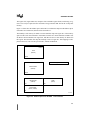
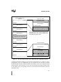
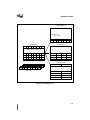
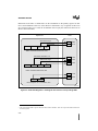
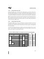
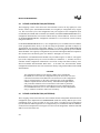
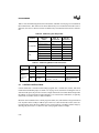
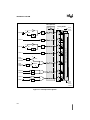
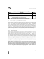
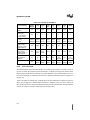
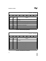
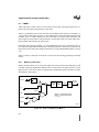
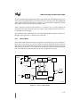
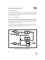
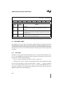
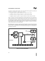
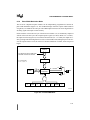
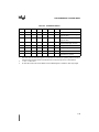
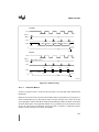
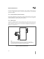
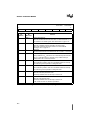
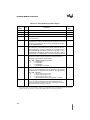
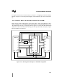
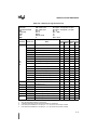
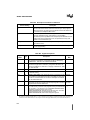
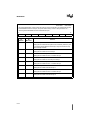
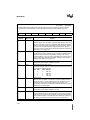
CHAPTER 6
INTERRUPT SYSTEM
6.1
OVERVIEW
The 8XC251Sx, like other control-oriented computer architectures, employs a program interrupt
method. This operation branches to a subroutine and performs some service in response to the
interrupt. When the subroutine completes, execution resumes at the point where the interrupt occurred. Interrupts may occur as a result of internal 8XC251Sx activity (e.g., timer overflow) or at
the initiation of electrical signals external to the microcontroller (e.g., serial port communication).
In all cases, interrupt operation is programmed by the system designer, who determines priority
of interrupt service relative to normal code execution and other interrupt service routines. Seven
of the eight interrupts are enabled or disabled by the system designer and may be manipulated
dynamically.
A typical interrupt event chain occurs as follows. An internal or external device initiates an interrupt-request signal. This signal, connected to an input pin (see Table 6-1) and periodically sampled by the 8XC251Sx, latches the event into a flag buffer. The priority of the flag (see Table 6-2,
Interrupt System Special Function Registers) is compared to the priority of other interrupts by the
interrupt handler. A high priority causes the handler to set an interrupt flag. This signals the instruction execution unit to execute a context switch. This context switch breaks the current flow
of instruction sequences. The execution unit completes the current instruction prior to a save of
the program counter (PC) and reloads the PC with the start address of a software service routine.
The software service routine executes assigned tasks and as a final activity performs a RETI (return from interrupt) instruction. This instruction signals completion of the interrupt, resets the interrupt-in-progress priority, and reloads the program counter. Program operation then continues
from the original point of interruption.
Table 6-1. Interrupt System Pin Signals
Signal
Name
INT1:0#
NOTE:
Type
Description
I
External Interrupts 0 and 1. These inputs set bits IE1:0 in the
TCON register. If bits IT1:0 in the TCON register are set, bits IE1:0
are controlled by a negative-edge trigger on INT1#/INT0#. If bits
INT1:0# are clear, bits IE1:0 are controlled by a low level trigger on
INT1:0#.
Multiplexed
With
P3.3:2
Other pin signals are defined in their respective chapters and in Appendix B, “Signal Descriptions.”
6-1