1
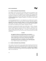
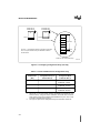
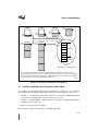
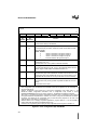
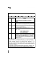
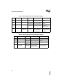
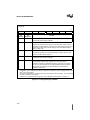
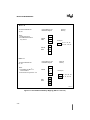
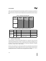
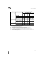
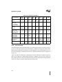
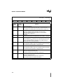
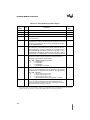
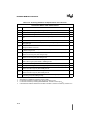
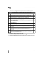
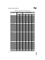
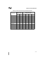
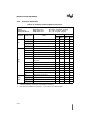
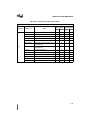
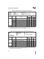
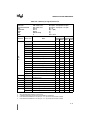
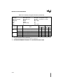
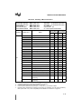
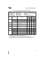
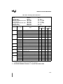
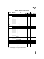
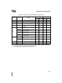
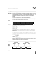
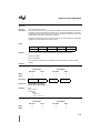
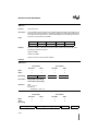
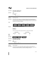
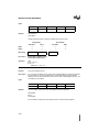
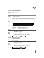
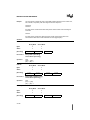
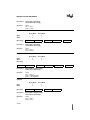
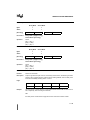
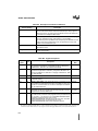
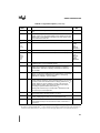
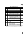
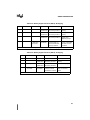
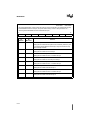
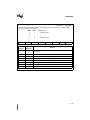
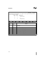
PROGRAMMING
5.2.4
Addressing Modes
The MCS 251 architecture supports the following addressing modes:
•
•
•
•
•
register addressing: The instruction specifies the register that contains the operand.
immediate addressing: The instruction contains the operand.
direct addressing: The instruction contains the operand address.
indirect addressing: The instruction specifies the register that contains the operand address.
displacement addressing: The instruction specifies a register and an offset. The operand
address is the sum of the register contents (the base address) and the offset.
• relative addressing: The instruction contains the signed offset from the next instruction to
the target address (the address for transfer of control, e.g., the jump address).
• bit addressing: The instruction contains the bit address.
More detailed descriptions of the addressing modes are given in “Data Addressing Modes” on
page 5-4, “Bit Addressing” on page 5-11, and “Addressing Modes for Control Instructions” on
page 5-13.
5.3
DATA INSTRUCTIONS
Data instructions consist of arithmetic, logical, and data-transfer instructions for 8-bit, 16-bit, and
32-bit data. This section describes the data addressing modes and the set of data instructions.
5.3.1
Data Addressing Modes
This section describes the data-addressing modes, which are summarized in two tables: Table 5-4
for the instructions that are native to the MCS 51 architecture, and Table 5-4 for the new data instructions in the MCS 251 architecture.
NOTE
References to registers R0–R7, WR0–WR6, DR0, and DR2 always refer to the
register bank that is currently selected by the PSW and PSW1 registers (see
“Program Status Words” on page 5-16). Registers in all banks (active and
inactive) can be accessed as memory locations in the range 00H–1FH.
5-4