1
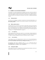
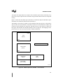
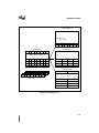
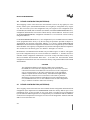
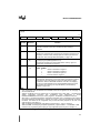
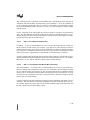
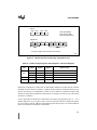
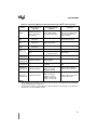
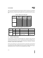
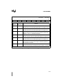
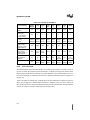
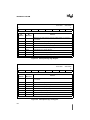
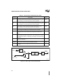
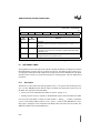
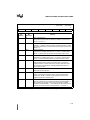
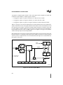
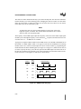
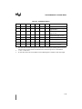
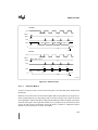
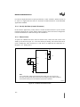
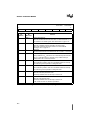
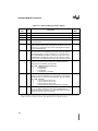
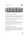
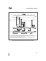
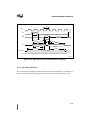
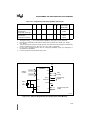
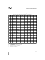
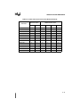
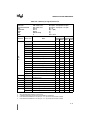
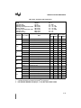
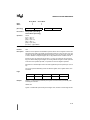
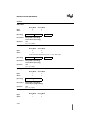
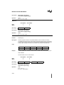
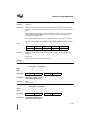
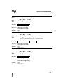
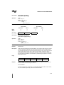
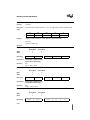
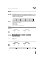
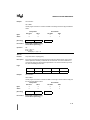
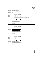
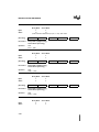
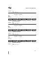
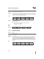
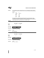
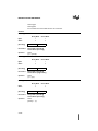
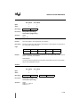
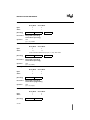
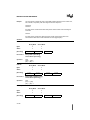
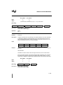
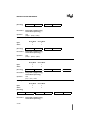
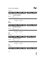
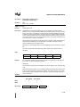
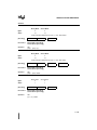
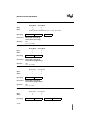
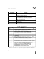
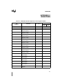
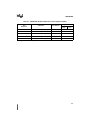
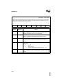
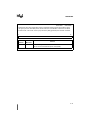
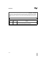
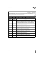
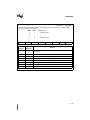
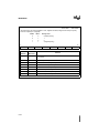
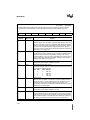
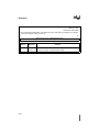
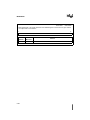
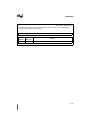
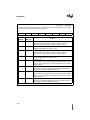
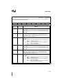
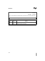
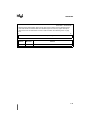
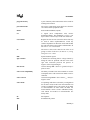
DEVICE CONFIGURATION
CONFIG1
(1), (2), (3)
7
0
—
—
Bit
Number
Bit
Mnemonic
7:5
—
—
INTR
WSB
—
—
EMAP
Function
Reserved:
Set these bits when writing to CONFIG1.
4
INTR
Interrupt Mode:
If this bit is set, interrupts push 4 bytes onto the stack (the 3 bytes of the PC
register and the PSW1 register). If this bit is clear, interrupts push 2 bytes onto
the stack (the 2 lower bytes of the PC register). See “Interrupt Stack Mode
(INTR)” on page 4-20.
3
WSB
Wait State B:
Clear this bit to generate one external wait state for memory region 01:. Set
this bit for no wait states for region 01:.
2:1
—
Reserved:
Set these bits when writing to CONFIG1.
0
EMAP
EPROM MAP:
Clearing this bit maps the upper 8 Kbytes of on-chip code memory
(FF:2000H–FF:3FFFH) to 00:E000H–00:FFFFH. If this bit is set, mapping
does not occur and addresses in the range 00:E000H–00:FFFFH access
external RAM. See “Mapping On-chip Code Memory to Data Memory
(EMAP#)” on page 4-20
NOTES:
1. Configuration bytes CONFIG0 and CONFIG1 define the configuration of the A-stepping version of the
MCS® 251 microcontroller.
2. To make the 8XC251SB pin compatible with 44-pin PLCC MCS 51 microcontrollers, use the following
bit values in CONFIG1: 1110 0111B.
3. Instructions for programming and verifying on-chip configuration bytes are given in Chapter 14.
Figure 4-6. Configuration Byte CONFIG1
4-10