Download Manual - Sin
Transcript
WATSON-MARLOW BREDEL MANUALS m-620dun-du-gb-02 Watson-Marlow 620DuN / 620Du pumps Contents 1 2 3 4 5 6 7 8 9 10 11 12 13 14 15 16 17 18 Declaration of conformity 3 Declaration of incorporation 3 Three-year warranty 3 When you unpack your pump 4 Information for returning pumps 5 Peristaltic pumps - an overview 5 Safety notes 6 Pump specifications 8 8.1 Pressure capability 12 8.2 Dimensions 13 Good pump installation practice 14 9.1 General recommendations 14 9.2 Do’s and do not’s 15 Connecting this product to a power supply 16 Start-up check list 17 Switching the pump on for the first time 17 Switching the pump on in subsequent power cycles (if not in auto-restart mode) 19 Manual operation 20 14.1 Keypad functions 20 14.2 Speed 22 14.3 Direction 22 14.4 Keypad lock 23 14.5 Keypad beep 23 14.6 Manual operation and remote digital inputs and outputs 23 14.7 Backlight 24 14.8 Auto-restart 24 Main menu 25 15.1 Keypad functions in menu screens 25 15.2 Main menu entry 25 Pin-secure process protection 27 Head and tubing calibration 28 Setup 31 18.1 Trim 32 18.2 Analogue 33 18.2.1 Input 1: speed 34 18.2.2 Scaling - stroke 35 18.2.3 Trim 36 18.2.4 Exit 36 18.3 Display 36 Watson-Marlow 620DuN and 620Du User Manual 18.4 18.5 18.6 18.7 18.8 18.9 18.10 18.11 18.12 18.13 19 20 21 22 Pump I/D 37 Baud 38 Stop bits 38 Xon/Xoff 38 Flow units 39 Run time 40 Outputs 40 Remote stop 42 Auto-restart 43 Set maximum allowed speed 44 18.14 Set minimum allowed speed 44 18.15 Scrolling 45 18.16 Date and time 45 18.17 Backlight 46 18.18 ROM 46 18.19 Language 47 18.20 Defaults 47 18.21 Beep 48 18.22 Security code 49 18.23 Exit 50 Pin out details 50 MemoDose 52 20.1 Changing dosing speed 53 20.2 Footswitch operation and other remote inputs and outputs with MemoDose 54 Exit 54 Automatic control wiring using the 620N module 55 22.1 620N module removal and replacement 55 22.2 Wiring up 56 22.3 Speed: analogue input 59 22.4 Scaling: analogue input 60 22.5 Speed: analogue output 61 22.6 Tachometer frequency output 61 22.7 Run/stop input 62 22.8 Direction input 62 22.9 Auto / manual toggle input 63 22.10 MemoDose input 63 22.11 Leak detection input 63 22.12 Outputs 1, 2, 3, 4 64 1 23 24 25 26 27 28 29 22.13 Supply voltages 22.14 RS485 input Automatic control wiring without the 620N module 23.1 Speed: analogue input 1 23.2 Scaling: analogue input 2 23.3 Speed: analogue output 23.4 Tachometer frequency output 23.5 Run/stop input 23.6 Direction input 23.7 Auto / manual toggle input 23.8 MemoDose input 23.9 Leak detection input 23.10 Pump status outputs 23.10.1 Logic output 1 23.10.2 Logic output 2 23.10.3 Logic output 3 23.10.4 Logic output 4 23.11 Supply voltages Automatic control and operation Network control and operation 25.1 RS232 and RS485 command strings Troubleshooting 26.1 Error codes Drive maintenance Drive spares 620RE, 620RE4 and 620R pumpheads 29.1 620RE, 620RE4 and 620R Key safety information 29.2 620RE, 620RE4 and 620R safe-guarding 29.3 620RE, 620RE4 and 620R pumping conditions 29.4 620RE, 620RE4 and 620R pump installation 29.5 620RE, 620RE4 and 620R general operation 29.6 620RE and 620RE4 tube element loading 29.7 620R continuous tube loading Watson-Marlow 620DuN and 620Du User Manual 29.8 64 65 66 68 69 70 70 71 71 72 72 73 74 74 75 76 76 77 78 80 30 31 32 33 82 83 84 85 85 86 86 34 86 87 87 88 35 36 37 89 90 38 39 620RE, 620RE4 and 620R tube element or continuous tube removal 91 29.9 620RE, 620RE4 and 620R maintenance 91 29.10 620RE, 620RE4 and 620R CIP and SIP 94 29.11 620RE, 620RE4 and 620R pumphead spares 95 620RE, 620RE4 and 620R performance data 97 30.1 620RE, 620RE4 and 620R flow rates 98 620R continuous tubing product codes 100 620RE and 620RE4 LoadSure tube element product codes 101 620L and 620LG pumpheads 102 33.1 620L and 620LG key safety information 102 33.2 620L and 620LG guarding102 33.3 620L and 620LG pumping conditions 103 33.4 620L and 620LG removal and installation 103 33.5 620L and 620LG tube loading 105 33.6 620L and 620LG care and maintenance 106 33.7 620L and 620LG track adjustment 106 33.8 620L and 620LG pumphead spares 107 620L and 620LG performance data 108 34.1 620L and 620LG flow rates 108 34.2 620L tubing codes 109 34.3 620LG element codes 110 Pumping accessories 110 Trademarks 111 Warning not to use pumps in patient-connected applications 111 Publication history 111 Decontamination certificate 112 2 DuN, Du 1 Declaration of conformity This declaration was issued for Watson-Marlow 620DuN and 620Du pumps on September 19, 2005. When this pump unit is used as a stand-alone pump it complies with: Machinery Directive 98/37/EC, Low Voltage Directive 73/23/EC, EMC Directive 89/336/EC. This pump is ETL listed: ETL control number 3050250. Cert to CAN/CSA std C22.2 No 61010-1. Conforms to UL std 61010A-1. See 8 Pump specifications. DuN, Du 2 Declaration of incorporation When this pump unit is to be installed into a machine or is to be assembled with other machines for installations, it must not be put into service until the relevant machinery has been declared in conformity with the Machinery Directive 98/37/EC BS EN 60204-1. Responsible person: Christopher Gadsden, Managing Director, Watson-Marlow Limited, Falmouth, Cornwall TR11 4RU, England. Telephone +44 (0) 1326 370370 Fax +44 (0) 1326 376009. The information in this user guide is believed to be correct at the time of publication. However, Watson-Marlow Limited accepts no liability for errors or omissions. Watson-Marlow Bredel has a policy of continuous product improvement, and reserves the right to alter specifications without notice. This manual is intended for use only with the pump it was issued with. Earlier or later models may differ. The most up-to-date manuals appear on the Watson-Marlow website: http://www.watson-marlow.com DuN, Du 3 Three-year warranty Watson-Marlow Limited warrants, subject to the conditions below, through either Watson-Marlow Limited, its subsidiaries, or its authorised distributors, to repair or replace free of charge, any part of this product which fails within three years of delivery of the product to the end user. Such failure must have occurred because of defect in material or workmanship and not as a result of operation of the product other than in accordance with the instructions given in this manual. Conditions of and specific exceptions to the above warranty are: Tubing and 620R, 620RE and 620RE4 rotors are consumable items and are excluded. Products must be returned by pre-arrangement, carriage paid, to WatsonMarlow Limited, its subsidiaries, or its authorised distributor. All repairs or modifications must have been made by Watson-Marlow Limited, its subsidiaries or its authorised distributors or with the express permission of Watson-Marlow Limited, its subsidiaries, or its authorised distributors. Products which have been abused, misused, or subjected to malicious or accidental damage or electrical surge are excluded. Watson-Marlow 620DuN and 620Du User Manual 3 Warranties purporting to be on behalf of Watson-Marlow Limited made by any person, including representatives of Watson-Marlow Limited, its subsidiaries, or its distributors, which do not accord with the terms of this warranty shall not be binding upon Watson-Marlow Limited unless expressly approved in writing by a Director or Manager of Watson-Marlow Limited. DuN, Du 4 When you unpack your pump Unpack all parts carefully, retaining the packaging until you are sure all components are present and in good order. Check against the components supplied list, below. Packaging disposal Dispose of packaging materials safely, and in accordance with regulations in your area. The outer carton is made of corrugated cardboard and can be recycled. Inspection Check that all components are present. Inspect components for damage in transit. If anything is missing or damaged, contact your distributor immediately. Components supplied 620Du and 620DuN pumps are available in two forms, dedicated to either 620R series pumpheads or 620L series pumpheads. Pumps are supplied as: Dedicated 620R pump drive unit fitted with 620R, 620RE or 620RE4 pumphead (see 8. Pump specifications); OR: Dedicated 620L pump drive unit fitted with 620L or 620LG pumphead (see 8. Pump specifications) A 620N module providing pump ingress protection to IP66, NEMA 4X, if a 620DuN. Note: the module is attached for transit, but must be removed to allow wiring up, voltage selection and fuse inspection and then re-affixed before the pump is operated. The designated mains power lead for your pump PC-readable CDROM containing these operating instructions Quick Start manual Note: Some versions of this product will include components different from those listed above. Check against your purchase order. Watson-Marlow 620DuN and 620Du User Manual 4 Storage This product has an extended shelf life. However, care should be taken after storage to ensure that all parts function correctly. Users should be aware that the pump contains a battery with an unused life of seven years. Long-term storage is not recommended for peristaltic pump tubing. Please observe the storage recommendations and use-by dates which apply to tubing you may wish to bring into service after storage. DuN, Du 5 Information for returning pumps Equipment which has been contaminated with, or exposed to, body fluids, toxic chemicals or any other substance hazardous to health must be decontaminated before it is returned to Watson-Marlow or its distributor. A certificate included at the rear of these operating instructions, or signed statement, must be attached to the outside of the shipping carton. This certificate is required even if the pump is unused. If the pump has been used, the fluids that have been in contact with the pump and the cleaning procedure must be specified along with a statement that the equipment has been decontaminated. DuN, Du 6 Peristaltic pumps - an overview Peristaltic pumps are the simplest pump, with no valves, seals or glands to clog or corrode. The fluid contacts only the bore of a tube, eliminating the risk of the pump contaminating the fluid, or the fluid contaminating the pump. Peristaltic pumps can run dry. How they work A compressible tube is squeezed between a roller and a track on an arc of a circle, creating a seal at the point of contact. As the roller advances along the tube, the seal also advances. After the roller has passed, the tube returns to its original shape, creating a partial vacuum which is filled by fluid drawn from the inlet port. Before the roller reaches the end of the track, a second roller compresses the tube at the start of the track, isolating a packet of fluid between the compression points. As the first roller leaves the track, the second continues to advance, expelling the packet of fluid through the pump’s discharge port. At the same time, a new partial vacuum is created behind the second roller into which more fluid is drawn from the inlet port. Backflow and siphoning do not occur, and the pump effectively seals the tube when it is inactive. No valves are needed. The principle may be demonstrated by squeezing a soft tube between thumb and finger and sliding it along: fluid is expelled from one end of the tube while more is drawn in at the other. Animal digestive tracts function in a similar way. Watson-Marlow 620DuN and 620Du User Manual 5 Suitable applications Peristaltic pumping is ideal for most fluids, including viscous, shear-sensitive, corrosive and abrasive fluids, and those containing suspended solids. They are especially useful for pumping operations where hygiene is important. Peristaltic pumps operate on the positive displacement principle. They are particularly suitable for metering, dosing and dispensing applications. Pumps are easy to install, simple to operate and inexpensive to maintain. DuN, Du 7 Safety notes In the interests of safety, this pump and the tubing selected should only be used by competent, suitably trained personnel after they have read and understood this manual, and considered any hazard involved. If the pump is used in a manner not specified by Watson-Marlow Limited, the protection provided by the pump may be impaired. This symbol, used on the pump and in this manual, means: Caution, risk of electric shock. This symbol, used on the pump and in this manual, means: Caution, refer to accompanying documents. This symbol, used on the pump and in this manual, means: Do not allow fingers to contact moving parts. This symbol, used on the pump and in this manual, means: Recycle this product under the terms of the EU Waste Electrical and Electronic Equipment (WEEE) Directive. Fundamental work with regard to lifting, transportation, installation, starting-up, maintenance and repair should be performed by qualified personnel only. The unit must be isolated from mains power while work is being carried out. There is a user-replaceable type T5A H 250V fuse in the fuseholder in the centre of the switchplate at the back of the pump. The 620N module must be removed, if a 620DuN, to allow access to the switchplate. See 22.1 620N module removal and replacement. There are thermal fuses within the pump which self-reset within 60 seconds; if they trip an error code is displayed. This pump contains no user-serviceable fuses or parts. Watson-Marlow 620DuN and 620Du User Manual 6 Any person who is involved in the installation or periodic maintenance of this equipment should be suitably skilled or instructed and supervised using a safe system of work. In the UK this person should also be familiar with the Health and Safety at Work Act 1974. There are moving parts inside the pumphead. Before opening the toolunlockable fixed guard (620R) or tool-unlockable track (620L), ensure that the following safety directions are followed. Ensure that the pump is isolated from the mains power. Ensure that there is no pressure in the pipeline. If a tube failure has occurred, ensure that any fluid in the pumphead has been allowed to drain to a suitable vessel, container or drain. Ensure that protective clothing and eye protection are worn if hazardous fluids are pumped. Primary operator protection from rotating parts of the pump is provided by the pumphead fixed guard. Note that guards differ, depending on the type of pumphead. See the pumphead sections of this manual: 29 and 33. Secondary operator protection from rotating parts of the pump is provided by indicator-only switching of the pumphead guard. This function will stop the pump if the guard is inadvertently opened while the pump is running. For details of permissible pumphead orientations, see the pumphead sections of this manual: 29 and 33. This pump must be used only for its intended purpose. The pump must be accessible at all times to facilitate operation and maintenance. Access points must not be obstructed or blocked. The pump’s mains plug is the disconnecting device (for isolating the motor drive from the mains supply in an emergency). Do not position the pump so that it is difficult to disconnect the mains plug. Do not fit any devices to the drive unit other than those tested and approved by Watson-Marlow. Doing so could lead to injury to persons or damage to property for which no liability can be accepted. This product does not comply with the ATEX directive and must not be used in explosive atmospheres. If hazardous fluids are to be pumped, safety procedures specific to the particular fluid and application must be put in place to protect against injury to persons. The exterior surfaces of the pump may get hot during operation. Do not take hold of the pump while it is running. Let it cool after use before handling it. No attempt should be made to run the drive without a pumphead fitted. The pump weighs more than 18kg (the exact weight depends on model and pumphead—see 8 Pump specifications). Lifting should be performed according to standard Health and Safety guidelines. Finger recesses are built into the sides of the lower shell for convenience in lifting; in addition, the pump can conveniently be lifted by grasping the pumphead and (where fitted) the 620N module at the rear of the pump. Watson-Marlow 620DuN and 620Du User Manual 7 8 Pump specifications DuN DuN, Du Labels fixed to the rear of the pump contain manufacturer and contact details, product reference number, serial number and model details. The same information is carried on the drive’s backplate, accessible when the 620N module is removed. The picture below is how a 620Du looks from the box. The number of connectors varies according to the model. 620DuN, IP66 NEMA 4X model and 620Du, IP31 model This pump can be controlled from the keypad or remotely. It features: Manual control Speed adjustment; run and stop; direction control; keypad scaling; “max” key for rapid priming. Remote control The pump can be digitally controlled with a contact closure or logic input signal. Analogue control The pump speed can be controlled through an analogue signal input in the ranges 0-10V, 1-5V or 4-20mA. Scaling can be controlled similarly using Analogue signal input 2. Watson-Marlow 620DuN and 620Du User Manual 8 Outputs A 0-10V, 4-20mA or 0-1478Hz output signal provides feedback of the pump speed. There are four relay status outputs which can be configured in software for a variety of pump parameters. MemoDose Allows repeat dosing. Stores in memory a pulse count from the motor. This count is repeated each time START is pressed to provide a single-shot dose. Calibration Full calibration with default figures for a range of pumpheads and tubes. Calibration dose facility. Serial communications Full pump control from a PC or other controller with the ability to network up to 16 pumps (620Du) or 32 pumps (620DuN). Guard switch Primary operator protection from rotating parts of the pump is provided by the fixed guard. Secondary operator protection from rotating parts of the pump is provided by indicator-only switching of the pumphead guard. PIN-secure process protection Two levels of control protection: main PIN code and user PIN code. IP (Ingress Protection) and NEMA definitions IP 1st Digit 3 Protected against ingress of solid objects with a diameter of more than 2.5mm. Tools, wires etc with a thickness of more than 2.5mm are prevented from approach 5 Protected against harmful dust deposits. Ingress of dust is not totally prevented but the dust must not enter in sufficient quantity to interfere with satisfactory operation of the equipment. Complete protection against contact 6 NEMA 2nd Digit Protection against ingress of dust (dusttight). Complete protection against contact 1 5 6 Protection against dripping water falling vertically. No harmful effect must be produced Protection against water projected from a nozzle against the equipment (enclosure) from any direction. There must be no harmful effect (water jet) Protection against heavy seas or powerful water jets. Water must not enter the equipment (enclosure) in harmful quantities (splashing over) 2 Indoor use to provide a degree of protection against limited amounts of falling water and dirt 12 Indoor use to provide a degree of protection against dust, falling dirt and dripping, noncorrosive liquids 13 Indoor use to provide a degree of protection against dust and spraying of water, oil and non-corrosive coolants 4X Indoor or outdoor use* to provide a degree of protection against splashing water, windblown dust and rain, hose-directed water; undamaged by the formation of ice on the enclosure. (Resist corrosion: 200-hour salt spray) * 620 cased pumps are rated to NEMA 4X (indoor use) only. Unit weights + 620RE4 + 620L, 620LG 16.5kg, 36lb 6oz 19.6kg, 43lb 3oz Drive only 20.1kg, 44lb 5oz 24.3kg, 53lb 9oz IP66 NEMA 4X 17.4kg, 38lb 6oz 20.5kg, 45lb 3oz 21.0kg, 46lb 5oz 25.2kg, 55lb 9oz IP31 Watson-Marlow 620DuN and 620Du User Manual + 620R, 620RE 9 Pump specifications Control range (turndown ratio) Supply voltage/frequency Maximum voltage fluctuation Installation category (overvoltage category) Power consumption Full load current Eprom version Enclosure rating - 620DuN Enclosure rating - 620Du 0.1-265rpm (2650:1) Filtered 100-120V/200-240V 50/60Hz 1ph ±10% of nominal voltage. A well regulated electrical mains supply is required along with cable connections conforming to the best practice of noise immunity II 250VA <1.1A at 230V; <2.2A at 115V Accessible through pump software IP66 to BS EN 60529; Equivalent to NEMA 4X to NEMA 250* (indoor use). Suitable for heavy industrial, process and filthy environments. The drive uses a Gore membrane vent to equalise the pressure inside the enclosure and to prevent ingress of water and corrosive vapours. IP31 to BS EN 60529. Equivalent to NEMA 2, suitable for indoor use. Protected against dripping water and falling dirt. May be wiped with a damp cloth, but should not be immersed. Pumphead options (620R models) 620R, 620RE, 620RE4 Pumphead options (620L models) 620L, 620LG Operating temperature range Storage temperature range Maximum altitude Humidity (non-condensing) (620Du) Humidity (condensing) (620DuN) Weight Noise 5C to 40C, 41F to 104F -25C to 65C, -13F to 149F 2,000m, 6,560ft 80% up to 31C, 88F, decreasing linearly to 50% at 40C, 104F 10% - 100% RH See table on previous page <70dB(A) at 1m * Protect from prolonged UV exposure. Watson-Marlow 620DuN and 620Du User Manual 10 Standards Safety of machinery—electrical equipment of machines: BS EN 60204-1 Safety requirements for electrical equipment for measurement, control and laboratory use: BS EN 61010-1 incorporating A2 Category 2, Pollution degree 2 Degrees of protection provided by enclosures (IP code): BS EN 60529 amendments 1 and 2 Conducted emissions: BS EN 55011 A1 and A2, Class A, called by BS EN 61000-6-4 Radiated emissions: BS EN 55011 A1 and A2, Class A, called by BS EN 61000-6-4 Electrostatic discharge: BS EN 61000-4-2 A1 and A2 EC harmonised standards Radiated RF immunity: BS EN 61000-4-3 A1 and A2, called by BS EN 61000-6-2 Fast transient burst: BS EN 61000-4-4 A1 and A2, Level 3 (2kV), called by BS EN 61000-6-2 Surge testing: BS EN 61000-4-5 A1 and A2, called by BS EN 61000-6-2 Conducted RF immunity: BS EN 61000-4-6, called by BS EN 61000-6-2 Voltage dips and interruptions: BS EN 61000-4-11, called by BS EN 61000-6-2 Mains harmonics: BS EN 61000-3-2 Ed 2 Safety of machinery—basic concepts, general principles of design: BS EN 292-1 and BS EN 292-2 Pumps and pump units for liquids—common safety requirements: BS EN 809 UL 61010A-1 CAN/CSA-C22.2 No 61010-1 Other standards Conducted emissions FCC 47CFR, Part 15.107 Radiated emissions FCC 47CFR, Part 15 NEMA 4X to NEMA 250 (indoor use) for IP66 products only Watson-Marlow 620DuN and 620Du User Manual 11 8.1 Pressure capability This pump’s default running speed is 165rpm. It can be run at any speed up to 265rpm. Please note, however: The 620RE and 620RE4 rotor warranty is limited to 2 bar from 165rpm to 265rpm. A warning is displayed when the user sets the speed above 165rpm. Note: Applies to 620RE MarkII and 620RE4 MarkII pumpheads only. (The 620LG is not limited). The pump’s software records the duration of operation above 165rpm. Watson-Marlow 620DuN and 620Du User Manual 12 8.2 Dimensions Watson-Marlow 620DuN and 620Du User Manual 13 DuN, Du 9 Good pump installation practice 9.1 General recommendations Position A correctly engineered installation will promote long tube life. Site the pump on a flat, horizontal, rigid surface, free from excessive vibration, to ensure correct lubrication of the gearbox. Allow a flow of air around the pump to ensure that heat can be dissipated. Ensure that the temperature around the pump does not exceed 40C. Do not stack other 620 pumps on top of this pump. It is, however, acceptable to stack other equipment on the upper surface of the 620 (as long as the ambient temperature does not exceed 40C). Emergency disconnection The pump’s mains plug is the disconnecting device (for isolating the motor drive from the mains supply in an emergency). Do not position the pump so that it is difficult to disconnect the mains plug. The STOP key on the keypad will always stop the pump. However, it is recommended that a suitable local emergency stop device is fitted into the mains supply to the pump. Valves Peristaltic pumps are self-priming and self-sealing against backflow. No valves are required in inlet or discharge lines. Valves in the process flow must be opened before the pump operates. Users are advised to fit a pressure relief device between the pump and any valve on the discharge side of the pump to protect against damage caused by accidental operation with the discharge valve closed. The pump may be set up so that the direction of rotor rotation is clockwise or counter-clockwise, whichever is convenient. Tubing materials: run-in advice Sta-Pure and Marprene TM tubing are hard to compress when new. When using tubing made of these materials, the first five pumphead revolutions should be at a speed of 10rpm or greater. If the pump is run slower, the safety system built into pump drive’s software may cause it to stop and display an over-current error message. Pressure advice In most circumstances, rotor and tube life are maximised if the pumphead is run slowly, particularly when pumping at high pressure. However, to maintain performance at pressures above 2 bar, avoid running the pumphead below 50rpm. If low-flow, high-pressure operation is necessary, switching to a smaller tube is recommended. Watson-Marlow 620DuN and 620Du User Manual 14 9.2 Do’s and do not’s Do not build a pump into a tight location without adequate airflow around the pump. Do ensure that when the 620N watertight module is fitted the seals are intact and properly located. Ensure that the holes for cable glands are properly sealed to maintain the IP66 / NEMA 4X rating. Do not strap the control and mains power cables together. Do keep delivery and suction tubes as short and direct as possible - though ideally not shorter than 1m - and follow the straightest route. Use bends of large radius: at least four times the tubing diameter. Ensure that connecting pipework and fittings are suitably rated to handle the predicted pipeline pressure. Avoid pipe reducers and lengths of smaller bore tubing than the pumphead section, particularly in pipelines on the suction side. Any valves in the pipeline (not usually needed) must not restrict the flow. Any valves in the flow line must be open when the pump is running. Do use suction and delivery pipes equal to or larger than the bore of the tube in the pumphead. When pumping viscous fluids use pipe runs with a bore several times larger than the pump tube. Do ensure that on longer tube runs at least 1m of smooth bore flexible tubing is connected to the inlet and discharge port of the pumphead to help to minimize impulse losses and pulsation in the pipeline. This is especially important with viscous fluids and when connecting to rigid pipework. Do site the pump at or just below the level of the fluid to be pumped if possible. This will ensure flooded suction and maximum pumping efficiency. Do keep the pumphead track and all moving parts clean and free from contamination and debris. Do run at slow speed when pumping viscous fluids (though see Pressure advice in 9.1 General recommendations). Flooded suction will enhance pumping performance in all cases, particularly for materials of a viscous nature. Do recalibrate after changing pump tubes, fluid, or any connecting pipework. It is also recommended that the pump is recalibrated periodically to maintain accuracy. IP66 / NEMA 4X models may be hosed down, but should not be immersed. Protect from prolonged UV exposure. IP31 models may be wiped with a damp cloth, but should not be hosed or immersed. The front of IP31 models is further protected against light spillages onto the pump. When using Marprene or Bioprene continuous tubing, do re-tension the tube after the first 30 minutes of running. Tube selection: The chemical compatibility lists published in Watson-Marlow publications are guides. If in doubt about the compatibility of a tube material and the duty fluid, request a Watson-Marlow tube sample card for immersion trials. Watson-Marlow 620DuN and 620Du User Manual 15 DuN, Du 10 Connecting this product to a power supply A well regulated electrical mains supply is required along with cable connections conforming to the best practice of noise immunity. It is not recommended to site these drives alongside “dirty” electrical mains supplies such as 3-phase contactors and inductive heaters without special attention being paid to unacceptable mains-borne noise. The voltage selector is mounted in the switchplate at the rear of the pump, protected from water by the 620N module (620DuN). The module must be removed to allow access to the switchplate. See 22.1 620N module removal and replacement. Set the voltage selector to 115V for 100-120V 50/60Hz supplies or 230V for 200-240V 50/60Hz supplies. Always check the voltage selector switch before connecting the mains supply. Make suitable connection to an earthed, single-phase mains electricity supply. We recommend using commercially available supply voltage surge suppression where there is excessive electrical noise. Power cable: The pump is supplied fitted with either of two cable glands and approximately 2.8m of power cable. The European cable is to Harmonised code H05RN-F3G0.75, used with our gland part number SL0128 which is suitable for an outside cable sheath diameter of 4-7mm. The north American cable is to type SJTOW 105C 3-18AWG VW-1 used with our gland part number SL0123 which is suitable for an outside cable sheath diameter of 7-9mm. DuN Power cables of NEMA 4X specification pumps are fitted with a standard US mains power plug. IP66 specification pumps are supplied with no plug. Wiring a mains plug must only be undertaken by suitably skilled, qualified personnel. Conductor coding line European North American brown black neutral blue white ground green/yellow green DuN The voltage selector switch is not visible while the 620N module is in place. Do not switch the pump on unless you have checked that it is set to suit your power supply by removing the module and inspecting the switch, and then refitting the module. See 22.1 620N module removal and replacement. DuN, Du If the mains power cable is inappropriate for your installation, it can be changed. Please contact your local Watson-Marlow Bredel service centre. Watson-Marlow 620DuN and 620Du User Manual 16 Input line fusing: type T5A H 250V 20mm time-delayed cartridge fuse, located in a fuseholder in the centre of the switchplate at the rear of the pump. Power interruption: This pump has an auto-restart feature which, when active, will restore the pump to the operating state it was in when power was lost. See 18.12 Auto-restart. Stop / start power cycles: Do not power up/power down for more than 100 starts per hour, whether manually or by means of the auto-restart facility. We recommend remote control where a high number of starts is required. DuN, Du 11 Start-up check list Note: See also 29.6, 29.7, 29.8 and 33.5, Tube loading. Ensure that proper connections are achieved between the pump tube and suction and discharge piping. Ensure proper connection has been made to a suitable power supply. Ensure that the recommendations in section 9 Good pump installation practice are followed. DuN, Du 12 Switching the pump on for the first time Note: This manual uses bold type to highlight the active option in menu screens: “English” in the first screen represented here. The active option appears on the pump display in inverse text. Switch on the power supply at the rear of the pump. The pump runs a poweron test to confirm proper functioning of the memory and hardware. If a fault is found, an error message is displayed. See 26.1 Error codes. The pump displays a language menu. Use the UP and DOWN keys to select your language. Press the ENTER key to confirm your choice. The information which follows assumes that your choice was English. Watson-Marlow 620DuN and 620Du User Manual 17 When the language is chosen this menu will not appear again and all menus will appear in the language you chose. (Language can be reset as described later. See 18.19 Language.) The pump displays the Watson-Marlow start-up screen for four seconds, followed by the pump model identity screen for four seconds, and then the manual mode main screen. The rotation symbol on the display indicates clockwise rotation. The default speed setting is 165rpm, but 265rpm is available (see 18.13 Set maximum allowed speed). Other initial start-up operational parameters are listed in the table below. First-time start-up defaults Language Not set Analogue input 4-20mA Speed 165rpm User trim None Direction Clockwise Remote stop Open=run Pumphead 620R Pump number 1 Tube size 15.9mm Baud rate 9600 Calibration 620R 15.9mm tube Stop bits 2 Backlight On Xon/Xoff Off Keypad lock Off Scrolling increment 0.1rpm Auto-restart Off Output 1 Run/Stop * Scaling Off Output 2 Direction † Pump status Stopped Output 3 Auto/Man ‡ Beeper On Output 4 General alarm Manual screen rpm * Run = high Security code † Clockwise rotation = high ‡ Auto = high Not set Note: The settings shown above for Run, Clockwise rotation and Auto are those in force on initial start-up for the functions available on Output 1, Output 2 and Output 3 respectively. For example, a high signal on Output 2 indicates clockwise rotation. These can be changed later according to user requirements. Note: High is equivalent to the common and normally open contacts of the relay on the adapter board being closed. The pump is now ready to operate according to the defaults listed above. All operating parameters may be changed by means of key-presses. See 14 Manual operation. Watson-Marlow 620DuN and 620Du User Manual 18 DuN, Du 13 Switching the pump on in subsequent power cycles (if not in auto-restart mode) Switch on the power supply at the rear of the pump. The pump runs a poweron test to confirm proper functioning of the memory and hardware. If a fault is found, an error message is displayed. See 26.1 Error codes. The pump displays the Watson-Marlow start-up screen for four seconds followed by the pump model identity screen for four seconds, and then the manual mode main screen. Note: Once in the manual mode main screen, keys assume their normal functions - see 15.1 Keypad in menu screens below. A subsequent press on START causes the pump to operate. Start-up defaults are those in place when the pump was switched off last. Check that the pump is set to operate as you require it. The pump is now ready to operate. All operating parameters may be changed by means of key-presses. See 14 Manual operation below. Watson-Marlow 620DuN and 620Du User Manual 19 DuN, Du 14 Manual operation 14.1 Keypad functions All settings and functions of the pump in manual mode are set and controlled by means of key-presses. Immediately after the start-up display sequence detailed above, the manual mode main screen will be displayed. The currently selected rotation direction is indicated on the display by a clockwise or counter-clockwise segmented arrow. If an exclamation mark ( ! ) shows, it indicates that Auto-restart is on. If a padlock icon ( ) shows, it indicates that Keypad lock is on. Note: A number of the controls listed below are shortcuts to commands which are also available through the Main menu. See 15 Main menu. Note: SHIFT gives access to functions which appear on the upper part of numeric keys. To access the MAX function, for example, press SHIFT once and release it. A symbol appears in the bottom left of the display to indicate that the next keypress will be SHIFTed. Press 4 (MAX). A brief single press on each key triggers a beep sound (if enabled - see 14.5 Keypad beep) and causes the pump to function as follows: START: starts the pump at the speed and in the direction shown on the display. The rotation symbol will become animated to confirm that the pump is operating. If the pump is running when START is pressed, it causes the information shown on the manual mode main screen to cycle from revolutions per minute, to flowrate in a choice of units (via a warning screen if flowrate has not been calibrated and if this is the first cycle since power-up) to rpm, flowrate and Run time. An example is shown here. The default can be altered from within the Setup menu (see 18.3 Display). MAX (SHIFT, 4): while pressed, MAX (SHIFT, 4) operates the pump at the maximum allowed speed and in the direction shown on the display. When released, the pump returns to its previous status. Note: Priming can be achieved by pressing MAX (SHIFT, 4) until fluid flows through the pump and reaches the point of discharge, and then releasing MAX (SHIFT, 4). Watson-Marlow 620DuN and 620Du User Manual 20 AUTO (SHIFT, 9): has no effect if the pump is running in auto mode. Stops the pump if it is running in Manual mode and displays a screen offering three choices: manual control, analogue control or network control. Use the UP and DOWN keys to make a choice. Press the ENTER key to confirm your decision. When started under analogue or network control, the pump runs at the speed set by any analogue or serial communications signal applied to the pump, and in the direction shown in the display. MAN (SHIFT, 6): stops the pump if it is running in an auto mode and displays the manual mode main screen. Has no effect if the pump is already running in manual mode. STOP: if the pump is running, pressing STOP stops the pump. The display will continue to show the previous speed and direction. The pump will return to this speed and direction when the START key is pressed again. UP: increases the speed shown on the display in minimum steps of 0.1rpm, or other steps as pre-selected in the Scrolling section of Setup (18.15), (unless the speed displayed is already the maximum allowed speed). If the pump is then started by pressing the START key, it will operate at the new speed. If the pump is running when UP in pressed, the change takes effect immediately. Note: If the pump’s flow rate has been calibrated (see 17 Calibration), after a speed change a screen showing the new rpm figure and the new flowrate is displayed for four seconds before returning the user to the previously set manual mode main screen: rpm or flowrate. DOWN: decreases the speed shown on the display in minimum steps of 0.1rpm, or other steps as pre-selected in the Scrolling section of Setup (18.15). If the pump is then started by pressing the START key, it operates at the new speed. The minimum speed possible is 0.1rpm. If the pump is running when DOWN is pressed, the change takes effect immediately. Note: If the pump’s flow rate has been calibrated (see 17 Calibration), after a speed change a screen showing the new rpm figure and the new flowrate is displayed for four seconds before returning the user to the previously set manual mode main screen: rpm or flowrate. Note: You can reduce the pump speed from 0.1rpm (or any other minimum displayed unit of speed as selected in the Scrolling section of Setup (18.15)) to 0rpm by a further press on the DOWN key. The pump is still in the running state and the rotation symbol will continue to move. Press the UP key to return the pump to the minimum speed. Note: If a minimum allowed speed has been set in the Set Min Speed section of the Setup menu, the above note on speed reduction to 0rpm does not apply. DIRECTION (SHIFT, 1): toggles the direction of rotation shown on the display. If the pump is then started by pressing the START key, it rotates in the new direction. If the pump is running when DIRECTION is pressed, the change takes effect immediately. ENTER: is used to enter/confirm numeric and menu selections. Also cycles the information shown on the manual mode main screen exactly as START does, whether the pump is running or not. See START, above. MENU (SHIFT, 7): causes the main menu to be displayed, from which all aspects of pump setup can be controlled. See 15 Main menu. CLEAR (SHIFT, 5): clears numeric entries so that they can be entered again. CAL (SHIFT, 8): takes the user to the calibrate sequence. . (decimal point, period) (SHIFT, 0): used in numeric expressions as a decimal point. To enter 5.3, press 5, SHIFT, 0, 3. (Some languages use , (comma) to represent a decimal point. This pump uses .) Watson-Marlow 620DuN and 620Du User Manual 21 Keypress combinations cause the pump to function as follows: Note: A number of the controls listed below are shortcuts to commands which are also available through the Main menu. See 15 Main menu. UP and 1 (DIRECTION) on power-up: toggles the keypad beep on and off. START on power-up: switches on the Auto-restart facility. See 18.12 Autorestart. STOP on power-up: switches off the Auto-restart facility. See 18.12 Autorestart. STOP and UP while the pump is stopped: turns the display backlight on. STOP and DOWN while the pump is stopped: turns the display backlight off. SHIFT and UP: sets the pump to maximum allowed speed. Note: Unlike its action elsewhere, SHIFT must be pressed and held. Note: The MAX key has a similar function, but causes the pump to run at maximum allowed speed only while the key is pressed. SHIFT and DOWN: sets the pump to minimum allowed speed. Note: Unlike its action elsewhere, SHIFT must be pressed and held. 1 (DIRECTION) and DOWN, pressed simultaneously: interrupts the display to show the pump’s ROM version for four seconds. START pressed and held for four seconds: toggles the keypad lock on and off. Only the START and STOP keys are active when keypad lock is on. The padlock icon is displayed. STOP pressed and held for two seconds: toggles the keypad lock on and off. Only the START and STOP keys are active when keypad lock is on. The padlock icon is displayed. STOP STOP within half a second: shortcut entry to MemoDose; when in MemoDose, shortcut return to manual mode main screen. See 20 MemoDose. 14.2 Speed To change the running speed: Use the UP and DOWN keys to change the pump’s running speed within limits of 0.1 rpm or other minimum allowed speed and the maximum allowed speed. Note: You can reduce the pump speed from 0.1 rpm to 0 rpm by a further press on the DOWN key. The pump is still in the running state and the rotation symbol will continue to move. Press the UP key to return the pump to the minimum speed. Note: The maximum allowed speed of the drive defaults to 165rpm. It is possible to set this limit at any speed up to 265rpm. See 18.13 Set maximum allowed speed, and section 3 Three-year warranty. 14.3 Direction To toggle the pump’s rotation sense: Press DIRECTION (SHIFT, 1) to toggle the pump between clockwise and counter-clockwise rotation. Note: Direction control is available subject to access not being limited by security code. See 18.22 Security code. Watson-Marlow 620DuN and 620Du User Manual 22 14.4 Keypad lock The keypad can be locked to prevent changes to pump speed or other settings, and make it possible only to start or stop the pump. The padlock symbol shows on the display. While the pump is running, hold down the START key for two seconds. The padlock symbol shows and only the START and STOP keys function. The keypad may also be locked while the pump is stopped. Hold down the STOP key for two seconds. The padlock symbol shows and only the START and STOP keys function. To unlock the keypad while the pump is running hold down the START key for two seconds. The padlock symbol is removed. If the pump is stopped hold down the STOP key until the padlock symbol is removed. Note: Keypad lock is available subject to access not being limited by security code. See 18.22 Security code. 14.5 Keypad beep The pump keypad can operate silently or indicate a positive key-press with a beep sound. To toggle the sound on and off, stop the pump. Turn off the mains power switch at the rear of the pump. Depress the UP and 1 (DIRECTION) keys while switching on the mains power switch at the rear of the pump. See 18.21 Beep. 14.6 Manual operation and remote digital inputs and outputs The remote run/stop, direction and leak-detected inputs are operational. The remote status outputs are all fully functional. The STOP key acts as an emergency stop. The run/stop input will not start the pump in manual mode, but once the START key has been pressed, the remote run/stop input will stop and start the pump according to its operational state. (620DuN) If you invert the operation of the remote run/stop switch to operate as open=stop, you must connect the +5V terminal to the i/p terminal on the Run/stop input connector (J4), to be able to start the pump from the keypad. See 22.7 Run/stop input. (620Du) If you invert the operation of the remote run/stop switch to operate as open=stop, you must connect pin 7 to pin 19, lower D-connector, to be able to start the pump from the keypad. See 22.7 Run/stop input. If STOP is pressed the remote run/stop switch will have no effect. You cannot invert the polarity of the remote direction signal. Watson-Marlow 620DuN and 620Du User Manual 23 14.7 Backlight To turn the display backlight on: Depress the STOP and UP keys together. To turn the display backlight off: Depress the STOP and DOWN keys together. See 18.17 Backlight. 14.8 Auto-restart This pump offers an auto-restart feature. When active on power loss, it will restore the pump when power returns to the operating state it was in when power was lost. It does not operate when powering down in the middle of a dose; when the pump is restarted, it will await a press on the START key to begin the interrupted dose again. Auto-restart is retained while the pump is switched off. When the pump starts running look for the ! symbol on the display. This ! symbol indicates that the pump is set for auto-restart. Do not use auto-restart for more than 100 starts per hour. We recommend remote control where a high number of starts is required. To turn the auto-restart facility on: Turn off the mains power switch at the rear of the pump. Depress the START key while switching on the mains power switch at the rear of the pump. To turn the auto-restart facility off: Turn off the mains power switch at the rear of the pump. Depress the STOP key while switching on the mains power switch at the rear of the pump. Watson-Marlow 620DuN and 620Du User Manual 24 DuN, Du 15 Main menu 15.1 Keypad functions in menu screens In addition to their functions in other operations, the following keys have specific actions in menu screens: STOP: In general, STOP functions as a “go back” key, taking the user up one menu level without making a change. UP: The UP key is used in menu item selection: it moves a highlight up the menu. When a numerical entry screen is displayed, pressing UP increases the number displayed. DOWN: The DOWN key is used in menu item selection: it moves a highlight down a menu. When a numerical entry screen is displayed, pressing DOWN decreases the number displayed. ENTER: The ENTER key functions in a similar way to the “enter” key of a personal computer: it confirms key-presses made immediately before. In menu item selection, it triggers the action or display selected from a menu using the UP and DOWN keys. Note: Confirmation screens are displayed for 4 seconds. While they are displayed, a single press on any key removes them. 15.2 Main menu entry MENU (SHIFT, 7) displays the main menu and stops the pump if it is running in Manual mode. It operates at any point in the pump’s activity except where error screens are displayed, where UP and DOWN keys are used to enter values, or where a PIN is requested. The main menu offers five options: Calibrate, Setup, Pin out details, MemoDose and Exit. Use the UP and DOWN keys to make a choice. Press the ENTER key to confirm your decision. Calibrate Calibrate allows the user to calibrate the pump with default figures for a range of pumpheads and tubes, as well as to refine the flowrate figures with a calibration dose facility. Setup Setup allows the user to set the pump’s operating parameters under 23 Trim, Analogue, Display, Pump I/D, Baud, Stop bits, Xon/Xoff, Flow units, Outputs, Remote stop, Auto-restart, Set max speed, Set min speed, Date/time, Backlight, ROM, Language, Defaults, Beep, Security code and Watson-Marlow 620DuN and 620Du User Manual headings: Run time, Scrolling, Exit. 25 Pin out details Du Selecting Pin out details causes the pump to display an information screen and then its preset pin and voltage details under 19 headings: Analogue input 1, Analogue input 2, Analogue output, Tacho output, Direction enable, Direction input, Run/Stop input, Leak input, Auto/Man toggle, Dose input, Output 1, Output 2, Output 3, Output 4, Supply, 0 volts, Earth, Others and Exit. DuN Pin out information is not relevant to the 620DuN IP66/NEMA 4X pumps. Selecting Pin out details causes the pump to display a warning screen and redisplay the main menu. DuN, Du MemoDose The MemoDose facility is used to remember the number of revolutions needed to dispense a previously dispensed volume of fluid, and cause the pump to dispense that volume repeatedly. Exit If Exit is selected, the pump returns to its last manual state with the pump stopped. Watson-Marlow 620DuN and 620Du User Manual 26 DuN, Du E SS C PROC TION P - S E CUR E IN 16 PIN-secure process protection E PROT The 620DuN and 620Du feature PIN-secure process protection. This allows the pump to be configured to suit the application, and for the setup to be protected by two levels of PIN code. Menu option or keypress With Main code set With User code set Code set and keypad locked Menu (SHIFT, 7) Available Available Not available Calibrate Available Available Not available Accept Available Available Not available Change Setup Cal (SHIFT, 8) Accept Main PIN needed Main PIN needed Available Main PIN or User PIN needed Main PIN needed; User PIN invalid Available Not available Not available Not available Available Available Not available Main PIN needed Main PIN or User PIN needed Not available Available Available Not available Main PIN needed Main PIN or User PIN needed Not available Auto (SHIFT, 9) Available Available Not available Man (SHIFT, 6) Available Available Not available Up Available Available Not available Down Available Available Not available SHIFT and Up Available Available Not available SHIFT and Down Available Available Not available Start Available Available Available Stop Available Available Available Enter Available Available Not available MemoDose Available Available Available Keypad lock Main PIN needed Main PIN or User PIN needed Main PIN or User PIN needed Auto-restart Available Available Available Change Max (SHIFT, 4) Dir (SHIFT,1) The main code gives access to Calibrate, Setup, Direction change and Keypad lock. The secondary (User) code permits Calibrate, Direction change and Keypad lock but bars Setup change. If either code is used in conjunction with Keypad lock, all keys are disabled except STOP and START. To activate and set a security code, see 18.22 Security code. If the main code is lost or forgotten: The Setup main security code can be bypassed by entering a special key sequence; all codes can then be cancelled and reset. Contact Watson-Marlow or your distributor for details. Watson-Marlow 620DuN and 620Du User Manual 27 DuN, Du 17 Head and tubing calibration The pump can display flowrate in a choice of units as well as speed in revolutions per minute. It must first be calibrated. Pump calibration can be limited to users who correctly enter a three-digit security code. If a security code has been set, selecting Change from the calibration details screen and confirming with the ENTER key causes the pump to display the Security code entry sequence. See 18.22 Security code. If no security code has been set, the pump displays the first screen of the calibration sequence. To dispense the correct amount of fluid the pump must know which pumphead is fitted and the tube size in the pumphead. The pump is pre-programmed with default flow rate figures for a range of pumpheads and tubes. You may also measure the flow from the pump and enter this value for the most accurate calibration. Use the UP and DOWN keys to highlight Calibrate in the main menu. Press ENTER to confirm. Alternatively ... Press CAL (SHIFT, 8) to enter the calibration screen from the main running screen, and return there after calibrating. Then: The pump displays its current settings: pumphead, tube size and flowrate; the default for each standard pumphead is the largest tube the pumphead can take. Example information is shown here. Use the UP and DOWN keys to highlight Accept or Change. Press ENTER to confirm. If Accept is selected, the default or previously set flowrate data for that pumphead and tube size are used. The pump displays the main running screen. If Change is selected with a security code in place, the pump starts its security code entry sequence. See 18.22 Security code. When the correct code is entered, the pump offers three options: Head and tube; Tube; and Calibration dose. If Change is selected with no security code in place, the three options are displayed immediately. Use the UP and DOWN keys to make a selection. Press ENTER to confirm. Watson-Marlow 620DuN and 620Du User Manual 28 Head and tube If Head and tube is selected, the pump displays a list of standard pumpheads that can be fitted to the pump. Use the UP and DOWN keys to make a selection. Press ENTER to confirm. An example is shown here. The pump displays tube sizes, as below. Tube If Tube is selected or a pumphead choice has just been made, the pump displays a list of standard tube sizes that can be used in the pumphead previously identified. Use the UP and DOWN keys to make a selection. Press ENTER to confirm. Watson-Marlow 620DuN and 620Du User Manual 29 Calibration dose The pump offers to run a calibration dose. Use the UP and DOWN keys to choose Yes or No. Press ENTER to confirm. Examples are shown here. If No is selected after a tube selection has been made (see Tube above), the pump briefly displays a confirmation screen showing current head, tube and flow settings, and redisplays the main menu. If Calibration dose is selected or if Yes is selected after a tube selection has been made (see Tube above), the pump displays the speed and direction at which it was last running in manual mode or to which it has just been set and invites the user to press START. Note: it is possible at this point to change the direction of rotation using the DIRECTION (SHIFT, 1) key, and to change the speed of rotation using the numeric keys (followed by ENTER), or the UP and DOWN keys, within the minimum and maximum limits that have been set. See 18.13 Set maximum speed and 18.14 Set minimum speed. Put a measuring container at the pump outlet. Press START. The pump runs for 4 minutes, displaying an information screen for 15 seconds and a further information screen for the rest of the 4 minutes. You may stop the calibration dose at any time with the STOP key - but allow the pump to run as long as possible to obtain the most accurate calibration. A minimum of 15 seconds is recommended. Watson-Marlow 620DuN and 620Du User Manual 30 Measure the quantity of fluid dispensed. The pump displays its calculated dose, based on previous calibration data. Use the numeric keys to adjust this reading to match the measured volume. Press ENTER. The pump briefly displays the new head, tube and flow settings, and displays the main running screen. Example figures are shown here. Note: If the pump has been set to display flow rate in units of mass (see 18.8 Flow units), as in this example, the pump displays a screen allowing you to confirm the specific gravity of the duty fluid immediately before the final press on ENTER. Note: if calibration was entered by pressing CAL (SHIFT, 8) from the main running screen, the pump redisplays the main running screen and restarts immediately without waiting for a further command. Note: Always recalibrate after changing pump tubes, fluid, or any connecting pipework. It is also recommended that the pump is recalibrated periodically to maintain accuracy. DuN, Du 18 Setup Entry to the Setup menu is from the Main menu and can be limited to users who correctly enter a three-digit security code. If a security code has been set, selecting Setup and confirming with the ENTER key causes the pump to display the Security code entry sequence. See 18.22 Security code. If no security code has been set, the pump displays the first of seven screens containing the Setup menu. The Setup menu The Setup menu occupies seven screens. The first two are shown here. To move from one screen to subsequent screens, repeatedly press DOWN. Each item is highlighted in turn until the last item on the screen is highlighted. A further press on the DOWN key displays the next screen of the menu, with the first item highlighted. Follow the reverse procedure using the UP key to move to an item on a previous screen of the menu. Make a selection using the UP or DOWN keys and press ENTER to confirm your choice. Watson-Marlow 620DuN and 620Du User Manual 31 18.1 Trim DuN Du Watson-Marlow 620DuN and 620Du User Manual 32 DuN, Du When the pump is under remote control, it tracks an analogue signal from the user’s remote control system to the i/p terminal of the Analogue 1 and Analogue 2 connectors at the rear of the pump within the ranges 4-20mA, 0-10V or 1-5V. The Trim setup sequence allows the user to customise the process-signal-to-pump-speed calibration. The sequence may be entered directly from the Setup menu or from the Analogue setup menu. Select Trim from the Setup menu or the Analogue setup menu using the UP or DOWN keys and press ENTER to confirm your choice. Apply the low process analogue signal to the i/p terminal of the Analogue 1 connector as instructed in the display. See 18.2 Analogue. While the signal is being applied, press ENTER to record the signal as a calibration point. Apply the maximum process control signal. While the signal is being applied, press ENTER to record the signal as a calibration point. Apply 50% of the maximum process control signal. While the signal is being applied, press ENTER to record the signal as a calibration point. If a mistake is made, press STOP at any point in the sequence, and the pump displays the previous screen. The final press on ENTER ends the Analogue 1 trimming sequence. If Analogue 2 has been configured, the pump displays a similar sequence of screens for that input. Apply the low, high and mid-range signal to the i/p terminal of the Analogue 2 connector as instructed in the display, pressing ENTER each time to record the signals as calibration points. If a mistake is made, press STOP at any point in the sequence, and the pump displays the previous screen. The final press on ENTER ends the Analogue 2 trimming sequence. When trimming is complete the pump displays a confirmation screen and redisplays the screen from which it entered the trim sequence: the Setup menu or the Analogue setup menu. The pump calculates linear responses from low to mid and from mid to high, and records the results as new analogue input calibration graphs. If any of the three signals applied to each input match, a warning screen is displayed before the confirmation screen appears, and the trim is ignored. Note: By applying the maximum process control signal when the minimum is requested and vice versa, inverted responses can be set up. Note: Resetting factory defaults clears the trim calibration values. 18.2 Analogue When the pump is under remote control, it tracks an analogue signal from the user’s remote control system to the i/p terminal of the Analogue 1 connector at the rear of the pump within the ranges 4-20mA, 0-10V or 1-5V. The Analogue option in the Setup menu allows the user to configure the pump to operate with his remote control system. Select Analogue from the Setup menu using the UP or DOWN keys and press ENTER to confirm your choice. Four options are displayed: Input 1 - speed, Scaling - stroke, Trim and Exit. Watson-Marlow 620DuN and 620Du User Manual 33 Input 1 - speed allows the user to tell the pump which signal type he will apply to Analogue 1, or to choose the program option. If he selects Program from the subsequent menu, the user can choose his input type and tell the pump the speeds at which to operate on receiving a low or high process control signal. See 18.2.1 Input 1 - speed. Scaling - stroke allows the user to disable scaling control, or if he wishes to enable scaling, to tell the pump which signal type he will apply to Analogue 2, or to choose the program option. If he selects Program from the subsequent menu, the user can choose his input type and tell the pump the speed proportion at which to operate on receiving a low or high process control signal. See 18.2.1 Input 1 - speed. Trim displays the Trim menu, described above. See 18.1 Trim. Exit returns the user to the first section of the Setup menu. See 18 Setup. 18.2.1 Input 1: speed Select Input 1 - speed using the UP or DOWN keys and press ENTER to confirm your choice. The pump offers three further choices: 4-20mA, 0-10V and 1-5V. Use the UP or DOWN keys to make a selection and press ENTER to confirm your decision. The pump configures the hardware and factory-set response data and briefly displays a confirmation screen. The user is returned to the Analogue setup display. Example figures are shown here. Alternatively the user can select Program to configure the pump to respond in a user-programmed way to any process signal range within 4-20mA, 0-10V or 1-5V. Watson-Marlow 620DuN and 620Du User Manual 34 Program Select Program using the UP or DOWN keys and press ENTER to confirm. The pump offers two choices: mA and V (0-10V). Use the UP or DOWN keys to make a selection and press ENTER to confirm your decision. The pump displays a screen allowing you to set the speed for low signal input (4mA or 0V). Use the UP and DOWN keys to scroll the display to your chosen speed and press ENTER to confirm the figure. The pump displays a screen allowing you to set the speed for high signal input (20mA or 10V). Use the UP and DOWN keys to scroll the display to your chosen speed and press ENTER to confirm the figure. If a mistake is made, the user may press STOP at any point in the sequence (before pressing ENTER on the high signal speed screen), and the pump displays the previous screen. The final press on ENTER causes the pump to configure the hardware and programmed response data. It briefly displays a confirmation screen and a warning that the analogue signal is not trimmed, and returns the user to the Analogue setup menu. Example values are shown here. 18.2.2 Scaling - stroke Select Scaling - stroke using the UP or DOWN keys and press ENTER to confirm your choice. The pump offers six further choices: Off, Keypad, 4-20mA, 0-10V, 1-5V and Program. Use the UP or DOWN keys to make a selection and press ENTER to confirm your decision. If Off is selected, scaling control is disabled and the pump displays the Analogue setup menu. The other options allow a choice of inputs to control scaling. If Keypad is selected, scaling will be controlled by entering the scaling factor using the UP and DOWN keys while the pump is running in Auto analogue mode. See 18.2 Analogue. The pump displays the Analogue setup menu. If 4-20mA, 0-10V or 1-5V is selected, the pump configures the hardware and calibration data appropriately. A confirmation screen is displayed briefly and the user is returned to the Analogue setup menu. If Program is selected, the pump offers: mA (4-20mA) and V (0-10V). Use Watson-Marlow 620DuN and 620Du User Manual 35 the UP or DOWN keys to make a selection and press ENTER to confirm your decision. The pump displays a screen inviting the user to enter the required speed proportion for low signal input (4mA or 0V) as a value from 0% to 100% Enter your value using the UP or DOWN keys and confirm by pressing ENTER. A similar screen allows the user to enter the required speed proportion for high signal input (20mA or 10V) as a value from 0% to 100%. Enter the value in the same way. If STOP is pressed at any point in the program setup (before pressing ENTER on the high signal speed proportion screen), the pump displays the previous screen. When high and low values have been entered and confirmed, the pump configures the hardware and basic calibration data. A confirmation screen is displayed briefly, followed by a warning that the analogue signal has not been trimmed. The user is returned to the Analogue setup screen. See 22.4 Scaling: analogue input 2 in Automatic control wiring. 18.2.3 Trim Trim displays the Trim menu, described above. See 18.1 Trim. It is recommended that a trim calibration is always performed to align the pump’s response to the actual process analogue signal. 18.2.4 Exit Exit returns the user to the first section of the Setup menu, described above. See 18 Setup. 18.3 Display The pump can display three default screens in manual mode: revolutions per minute, flowrate in a choice of units, or both. In the first screen of the Setup menu select Display using the UP and DOWN Watson-Marlow 620DuN and 620Du User Manual 36 keys. Press ENTER to confirm your choice. The pump displays a screen allowing you to choose the format of the manual mode main screen. Use the UP and DOWN keys to choose and press ENTER to confirm your decision. If you choose Flowrate and you have not calibrated the pump since switching it on, a warning screen is displayed for 4 seconds. The warning does not appear if the display screen formats are cycled again, unless the pump has been switched off in the mean time. The pump redisplays the first screen of the Setup menu. When the pump next runs, the manual mode main screen will display pump activity in rpm, flowrate (in the units you chose - see 18.8 Flow units) or both, according to your choice, plus a run time figure. Examples are shown here. Alternatively ... In the manual mode main screen, repeatedly press ENTER to cycle the display between rpm, flowrate (in the units you chose - see 18.8 Flow units) or combined, according to your choice. This cycle operates if the pump is running and if it is stopped. While the pump is running, you can cycle the display in the same way by repeatedly pressing START. In both cases, if you have not calibrated the pump since switching it on, a warning screen is displayed for 4 seconds before the flowrate screen appears. The warning does not appear if the display screen formats are cycled again, unless the pump has been switched off. The pump redisplays the first screen of the Setup menu. 18.4 Pump I/D The 620Du pump can be individually controlled under RS232 as one of up to 16 pumps. The 620DuN pump can be individually controlled under RS485 as one of up to 32 pumps. First the pump must be given its identity number. In the first screen of the Setup menu select Pump I/D using the UP and DOWN keys. Press ENTER to confirm your choice. The pump displays a screen allowing you to change the pump’s identity number. Use the numeric keys to enter a new number in the display and press ENTER to confirm your decision. An example is shown here. The pump displays the first screen of the Setup menu. Watson-Marlow 620DuN and 620Du User Manual 37 18.5 Baud The pump can be set to communicate with control devices at a choice of baud rates. In the first screen of the Setup menu select Baud using the UP and DOWN keys. Press ENTER to confirm your choice. The pump displays a screen allowing you to change the pump’s baud rate. Use the UP and DOWN keys to select 1200, 2400, 4800 or 9600 (or, 620DuN only, 19k2) and press ENTER to confirm your decision. The pump displays the first screen of the Setup menu. 18.6 Stop bits The pump can be set to communicate with control devices at a choice of stop bits settings. In the second screen of the Setup menu select Stop bits using the UP and DOWN keys. Press ENTER to confirm your choice. The pump displays a screen allowing you to change the pump’s stop bits setting. Use the UP and DOWN keys to select 2, 1, or 0 and press ENTER to confirm your decision. The pump displays the second screen of the Setup menu. 18.7 Xon/Xoff The pump can be set to communicate with control devices using Xon/Xoff flow control. In the second screen of the Setup menu select Xon/Xoff using the UP and DOWN keys. Press ENTER to confirm your choice. The pump displays a screen allowing you to set flow control on or off. Use the UP and DOWN keys to choose and press ENTER to confirm your decision. The pump displays the second screen of the Setup menu. Watson-Marlow 620DuN and 620Du User Manual 38 18.8 Flow units The pump can display its flow rate in metric (SI) or US (imperial) units of volume or mass. In the second screen of the Setup menu select Flow units using the UP and DOWN keys. Press ENTER to confirm your choice. The pump displays a screen offering Metric or US. Use the UP and DOWN keys to choose and press ENTER to confirm your decision. If you chose Metric, the pump offers a choice of units: ml/min, l/min, l/hr, g/min or kg/hr. Use the UP and DOWN keys to choose and press ENTER to confirm your decision. If you chose US, the pump offers a choice of units: US Gallons/hr, US Gallons/day, lb/hr or lb/day. Use the UP and DOWN keys to choose and press ENTER to confirm your decision. If you chose a volumetric flow rate from either screen, a confirmation screen appears briefly and the pump displays the second screen of the Setup menu. If you chose a mass flow rate from either screen, the pump asks for the specific gravity of the fluid to be pumped. Use the numeric keys to enter a value between 0.01 and 15.00. Press ENTER to confirm your decision. Press STOP if you decide to make a different choice of units. A confirmation screen appears briefly and the pump displays the second screen of the Setup menu. Watson-Marlow 620DuN and 620Du User Manual 39 18.9 Run time The pump cumulatively records hours of motor operation. The figure can be displayed or reset to zero. In the third screen of the Setup menu select Run time using the UP and DOWN keys. Press ENTER to confirm your choice. The pump briefly displays the total hours its motor has operated since the last time the counter was reset to zero hours, followed by an opportunity to reset the counter to zero hours. An example is shown here. Use the UP and DOWN keys to choose Yes or No and press ENTER to confirm your decision. The total hours screen is displayed with its total reset to zero, or unchanged, as appropriate. The pump displays the third screen of the Setup menu. Note: Run time is displayed on the Combined display. See 18.3 Display. Run time does not zero when factory default is selected. 18.10 Outputs DuN The 620DuN pump offers four relay status outputs. See 12 Switching the pump on for the first time for initial start-up defaults. Each of six parameters can be configured to any output, or more than one output. Du The 620Du pump offers four digital status outputs. See 12 Switching the pump on for the first time for initial start-up defaults. Each of six parameters can be configured to any output, or more than one output. The parameters are: DuN, Du Run/stop Provides a status output to indicate whether the pumphead is in a running or stopped condition. When running at 0rpm, the run/stop output indicates running. Direction Provides a status output to indicate which direction the pump is set to run in. Auto / man Provides a status output to indicate whether the pump is in analogue control mode or manual control mode. General alarm Provides an alarm output when any system error condition occurs except: leak detected; analogue signal out of range; analogue over-signal; analogue no signal. Watson-Marlow 620DuN and 620Du User Manual 40 Leak detected When used with a leak detector, this output provides an alarm when the pump has been automatically switched off following tube failure. Head Provides an alarm when the pumphead guard is open. If it is running, the pump will stop. DuN Outputs 1-4 are available as single-pole change-over relay contacts: Relay 1, 2, 3 and 4. Connect to the normally open or normally closed contacts of the relay as required and configure the pump’s software accordingly. See below in this section. Note: The maximum rating on the relay contacts of this pump is 30VDC; maximum load 30W. Du Output 1 and output 2 are available in two formats: From pins 10 and 11, lower D-connector, as 5V TTL signals. From pins 10 and 11, upper D-connector, as open collector logic outputs. Output 3 and output 4 provide open collector logic outputs from pins 13 and 12, upper D-connector, respectively. A supply voltage from the pump (5V, 10V, 12V) or user-supplied up to 30V to pin 22, upper D-connector, provides the voltage level for these logic status outputs. DuN, Du Watson-Marlow 620DuN and 620Du User Manual 41 In the third screen of the Setup menu select Outputs using the UP and DOWN keys. Press ENTER to confirm your choice. The pump displays a screen allowing you to configure each of the four outputs, or to exit this menu. Use the UP and DOWN keys to choose and press ENTER to confirm your decision. If Output 1 is chosen, the pump displays the six options. Selecting General, Leak or Head using the UP and DOWN keys and confirming the choice by pressing ENTER configures that option to Output 1, displays a confirmation screen, and returns the user to the Output selection screen. Selecting Run/Stop, Direction or Auto/Man using the UP and DOWN keys and confirming the choice by pressing ENTER displays screens allowing the user to configure Run to High or Low, Clockwise to High or Low, and Auto to High or Low respectively. Choose using the UP and DOWN keys and press ENTER to confirm. The option chosen is configured to Output 1. The pump displays a confirmation screen, and returns the user to the Output selection screen. The user can configure Output 2, Output 3 and Output 4 in the same way, or choose Exit. If STOP is pressed during configuration, the previous setting for the output is retained and the pump redisplays the Output selection screen. If Exit is chosen, the pump returns the user to the third screen of the Setup menu. 18.11 Remote stop DuN Du The 620DuN pump can be stopped and started with a remote switch between the 5V terminal and the i/p terminal of the Run/stop input, using an open=run or open=stop command sense. It also operates with a logic input between 5V and 24V on the i/p terminal of the Run/stop input. If remote switching is disabled, neither the remote run/stop nor direction signal inputs will affect the pump state. The 620Du pump can be stopped and started with a remote switch between pin 7 and pin 19 using an open=run or open=stop command sense. It also operates with a logic input between 5V and 24V on pin 7. If remote switching is disabled, neither the remote run/stop nor direction signal inputs will affect the pump state. DuN, Du In the third screen of the Setup menu select Remote stop using the UP and DOWN keys. Press ENTER to confirm your choice. The pump displays a screen allowing the user to disable the remote stop feature. Use the UP and DOWN keys to choose Yes or No and press ENTER to confirm the decision. If No is chosen, the pump asks the user to make a further choice, according to whether the pump is required to run on an open or closed remote switch: Open=stop or Open=run. Choose using the UP and DOWN keys and press Watson-Marlow 620DuN and 620Du User Manual 42 ENTER to confirm. The pump briefly displays a confirmation screen and returns the user to the third screen of the Setup menu. If Yes is chosen, the pump briefly displays a confirmation screen and returns the user to the third screen of the Setup menu. Example screens are shown here. Note: The confirmation screen indicates whether Remote stop is enabled or disabled, and displays the command sense of the remote control switch even if Remote stop has been disabled. This allows the command sense to be displayed if remote switching is disabled. Even with the remote stop function disabled, the pump could still start if the remote auto/manual toggle input is used to toggle the pump into analogue mode. 18.12 Auto-restart This pump offers an auto-restart feature. If active on power loss, it restores the pump when power returns to the operating state it was in when power was lost. It does not operate when powering down in the middle of a dose: when the pump is restarted, it will await a press on the START key to begin the interrupted dose again. Auto-restart is retained while the pump is switched off. When the pump starts running, look for the ! symbol on the display. This symbol indicates that the pump is set for auto-restart. In the fourth screen of the Setup menu select Auto-restart using the UP and DOWN keys. Press ENTER to confirm your choice. The pump displays a screen allowing the user to activate auto-restart. Use the UP and DOWN keys to choose On or Off and press ENTER to confirm the decision. If Off is chosen, the pump returns the user to the fourth screen of the Setup menu. The auto-restart facility will not operate. If On is chosen, the pump returns the user to the fourth screen of the Setup menu, where an exclamation mark ( ! ) is now visible. This mark confirms that the auto-restart feature is in place and will operate the next time power is lost and restored. Watson-Marlow 620DuN and 620Du User Manual 43 Alternatively ... Stop the pump. Turn off the mains power switch at the rear of the pump. Hold down the START key and turn on the mains power switch. The ! symbol shows on the display. Start the pump. If the mains supply is interrupted the pump will automatically restart when the mains power returns. To remove auto-restart switch off the mains power at the rear of the pump. Hold down the STOP key and turn the mains power switch on. The ! symbol does not appear. Do not use auto-restart for more than 100 starts per hour. We recommend remote control where a high number of starts is required. 18.13 Set maximum allowed speed The maximum allowed speed of the drive defaults to 165rpm. It is possible to set this limit at any speed down to 1rpm as long as the minimum allowed speed is at least 1rpm less, or up to 265rpm; however, see 8.1 Pressure capability for use above 165rpm. In the fourth screen of the Setup menu select Set max speed using the UP and DOWN keys. Press ENTER to confirm your choice. The pump displays a screen allowing the user to set the maximum speed of the pump equal to or lower than the maximum available. Use the numeric keys to set the maximum allowed speed and press ENTER to confirm the figure. The pump returns the user to the fourth screen of the Setup menu, via a warning screen requiring the user to press ENTER if he selected a speed greater than 165rpm. 18.14 Set minimum allowed speed The minimum allowed speed of the drive defaults to 0.1rpm. It is possible to set this limit at any speed up to 264rpm, as long as the maximum speed is at least 1rpm greater. In the fourth screen of the Setup menu select Set min speed using the UP Watson-Marlow 620DuN and 620Du User Manual 44 and DOWN keys. Press ENTER to confirm your choice. The pump displays a screen allowing the user to set the minimum speed of the pump equal to or higher than the minimum available. Use the numeric keys to set the minimum allowed speed and press ENTER to confirm the figure. The pump returns the user to the fourth screen of the Setup menu. 18.15 Scrolling The pump’s speed can be set, up to the maximum allowed speed and down to the minimum allowed speed, by pressing the numeric keys or by using the UP and DOWN keys. The numeric keys allow the user to select a speed in increments of one-tenth of a revolution per minute (or the equivalent in flow rate if the pump has been configured to display its performance in units of flow). The UP and DOWN keys allow the speed to be set in increments of the user’s choice: one-tenth of a revolution per minute; one half of a revolution per minute; one, two, five or ten revolutions per minute (or their equivalents in flow rate if the pump has been configured to display its performance in units of flow). Each press on UP, for example, offers a speed one increment greater than the current speed. Note: For 0.1rpm, 0.5rpm and 1rpm settings, the increments increase progressively as long as the UP or DOWN key is continually held down. In the fifth screen of the Setup menu select Scrolling using the UP and DOWN keys. Press ENTER to confirm your choice. The pump displays a screen allowing the user to set the UP and DOWN keys’ scrolling increment. Use the UP and DOWN keys to choose 0.1, 0.5, 1.0, 2.0, 5.0 or 10.0. Press ENTER to confirm your choice. The pump returns the user to the fifth screen of the Setup menu. Note: If the maximum allowed speed has been set to a figure which is not a multiple of the chosen increment, the last active press on UP raises the speed to that maximum rather than to the next multiple of the chosen increment. Similarly, if the pump is running at a speed which is not a multiple of the chosen increment, the first press on UP raises the speed to the next multiple of the chosen increment. 18.16 Date and time The pump’s real-time clock can be set with the date and time. In the fifth screen of the Setup menu select Date/time using the UP and DOWN keys. Press ENTER to confirm your choice. The pump displays any pre- Watson-Marlow 620DuN and 620Du User Manual 45 vious setting. If the setting displayed is correct, press ENTER. The pump redisplays the fifth screen of the Setup menu. If you wish to change the setting, use the UP and DOWN keys to enter the current date (two digits), month (three letters), year (four digits), hour, minute and second (all two digits), pressing ENTER to confirm each one. When ENTER is pressed to confirm the seconds, the pump redisplays the fifth screen of the Setup menu. 18.17 Backlight The pump’s display can be illuminated or not according to choice. In the fifth screen of the Setup menu select Backlight using the UP and DOWN keys. Press ENTER to confirm your choice. The pump displays a screen allowing the user to switch the display backlight on or off. Use the UP and DOWN keys to choose On or Off and press ENTER to confirm the decision. The pump returns the user to the fifth screen of the Setup menu. The display is now illuminated or not according to the user’s decision. Alternatively ... To turn the backlight off: press STOP and DOWN together. To turn the backlight on: press STOP and UP together. 18.18 ROM The pump can display its software version, model number and pump speed. In the fifth screen of the Setup menu select ROM using the UP and DOWN keys. Press ENTER to confirm your choice. The pump displays the software version, model number and the maximum allowed pump speed for four seconds (an example is shown here), then returns the user to the fourth screen of the Setup menu. It also displays a checksum: CHK 123, for example. This may be required if reporting pump performance to the Watson-Marlow service department. Alternatively ... Press 1 (DIRECTION) and DOWN together to interrupt the display and show the pump’s ROM version for four seconds. Watson-Marlow 620DuN and 620Du User Manual 46 18.19 Language The pump can be set to operate in several languages. In the sixth screen of the Setup menu select Language using the UP and DOWN keys. Press ENTER to confirm your choice. In the next screen, choose a language using the UP and DOWN keys. Press ENTER to confirm your choice. The pump redisplays the sixth Setup screen in your chosen language. All screens will subsequently appear in your chosen language. 18.20 Defaults All the pump’s user-set data can be reset to factory defaults. In the sixth screen of the Setup menu select Defaults using the UP and DOWN keys. Press ENTER to confirm your choice. A warning is displayed for four seconds, and the pump asks the user to confirm that factory defaults are to be reset. Use the UP and DOWN keys to choose Yes if you wish the pump to reset all user-set data back to factory defaults (see 12 Switching the pump on for the first time); or No if you do not wish to do this. Press ENTER to confirm your decision. If Yes was chosen, the pump resets its factory defaults and redisplays the sixth Setup screen. If No was chosen, the pump makes no changes to its setup and redisplays the sixth Setup screen. Watson-Marlow 620DuN and 620Du User Manual 47 
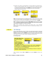
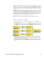
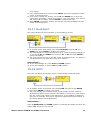
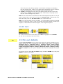
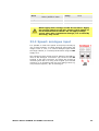
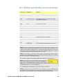
18.21 Beep The pump keypad can operate silently or indicate a positive key-press with a beep sound. In the sixth screen of the Setup menu select Beep using the UP and DOWN keys. Press ENTER to confirm your choice. In the next screen, use the UP and DOWN keys to choose On or Off. Press ENTER to confirm your decision. The pump redisplays the sixth Setup screen. Alternatively ... To toggle the sound on and off, stop the pump. Turn off the mains power switch at the rear of the pump. Depress the UP and 1 (DIRECTION) keys while switching on the mains power switch at the rear of the pump. Watson-Marlow 620DuN and 620Du User Manual 48 18.22 Security code Access to the pump’s Setup and Calibration menus, direction control and keypad lock can be restricted to those who correctly enter a three-digit security code: the main code. A secondary user code can be set, which permits PIN access to calibration, direction and keypad lock, but blocks access to Setup. See 18 Setup, 17 Calibrate, 14.3 Direction and 14.4 Keypad lock. The codes must first be set. In the sixth screen of the Setup menu select Security code using the UP and DOWN keys. Press ENTER to confirm your choice. If no code has been set, a screen is displayed inviting the user to set a main code. Press ENTER to proceed (or STOP to return to the sixth screen of the Setup menu). If a main code has been set, a screen is displayed inviting the user to set a new main code, to set a user code (or a new user code if one has already been set), or to cancel all codes. Choose Set main code, Set user code or Cancel codes using the UP and DOWN keys. Press ENTER to confirm your choice. If you chose Cancel codes, any codes previously set are cancelled and access to the pump is not restricted. If you chose Set main code or Set user code, the pump displays a screen with three blank spaces for digits and the instruction “Enter new code”. Use the numeric keys to enter three digits. The pump displays a similar three-digit entry screen and the instruction “Confirm code”. Repeat the digit-entry sequence. If the second three-digit code entered differs from the first, or if the digits chosen as a user code are the same as those already set as a main code, the pump briefly displays an error message and redisplays the set code options screen. If the codes tally and, for a user code, if there is no clash with a previously set Watson-Marlow 620DuN and 620Du User Manual 49 main code, the pump briefly displays a confirmation message and redisplays the sixth Setup screen. Access to the Setup and Configuration menus, direction control and keypad lock is now protected by the new security code. If STOP is pressed during code entry, the pump returns the user to the sixth Setup screen. If STOP is pressed during code confirmation, the pump returns the user to the first digit-entry screen. Note: A user code cannot be set unless a main code has previously been set. If you wish to cancel only a user code, you must use Cancel codes to cancel both user and main codes, then use Set main code to set a new main code. Note: If a code has been set but forgotten, it is still possible to access the Setup screens to cancel the code or reset it to another three-digit number. Contact your supplier or Watson-Marlow Technical support for the bypass sequence. 18.23 Exit In the seventh screen of the Setup menu Exit is highlighted. Press ENTER. The user is returned to the main menu. Du 19 Pin out details Selecting Pin out details from the main menu causes the pump to display an information screen and then its preset pin and voltage details under 18 headings: Analogue input 1, Analogue input 2, Analogue output, Tacho output, Direction enable, Direction input, Run/Stop input, Leak input, Auto/Man toggle, Dose input, Output 1, Output 2, Output 3, Output 4, Supply, 0 volts, Earth and Others. No user input is available in this section; it displays information only. In the main menu, select Pin out details using the UP or DOWN keys and press ENTER to confirm your choice. Watson-Marlow 620DuN and 620Du User Manual 50 The Pin out details menu The Pin out details menu occupies five screens. The first two are shown here. To move from one screen to subsequent screens, repeatedly press DOWN. Each item is highlighted in turn until the last item on the screen is highlighted. A further press on the DOWN key displays the next screen of the menu, with the first item highlighted. Follow the reverse procedure using the UP key to move to an item on a previous screen of the menu. Make a selection using the UP or DOWN keys and press ENTER to confirm your choice. The information on pin outs duplicates the details described in this instruction manual under Automatic control wiring. The screens available are all presented in a similar manner. For example, on selecting Analogue input 1, the following screen is displayed: This indicates that the analogue input signal must be applied to pin 4 of the lower D-connector at the rear of the pump, where 0 volts is available on pin 16. If the analogue input is configured for a 4-20mA signal, the maximum permitted voltage is 5 volts across the pump; if the analogue input is configured for a 0-10V or 1-5V signal, the maximum permitted voltage is 10 volts. The information available on selecting Supply and Others is presented on two screens each. Pressing DOWN when the first screen of each is displayed causes the second screen to appear. UP performs a similar function. Pressing STOP or ENTER in any Pin out information screen returns the user to the appropriate Pin out menu screen. To leave the Pin out menu screens Cycle through the Pin out menu screens until the fifth screen is displayed. Select Exit using the UP or DOWN keys and press ENTER to confirm your choice. Alternatively ... Repeatedly press STOP to go back level by level until the main menu is displayed. Watson-Marlow 620DuN and 620Du User Manual 51 DuN, Du 20 MemoDose Each time the pump is started by pressing START, it records the number of pumphead revolutions which occur until STOP is pressed. The number of revolutions is proportional to the volume of fluid which has been dispensed: the dose. The MemoDose facility allows the user to repeat-dose a precise volume of fluid. To do so, a quantity of fluid must be dispensed as the master dose which the MemoDose facility can repeat exactly or proportionately. To dispense a master dose In the manual mode main screen, set the appropriate pump speed and direction using the UP or DOWN keys and the DIRECTION (SHIFT, 1) key. An example is shown here. A slower speed may make it easier for the user to measure accurately - though it may not represent the duty condition. Place a suitable measuring vessel under the pump delivery tube. Press START. The pump runs and fluid is pumped into the vessel. When the required volume of fluid has been dispensed, it is necessary to stop the pump and display the MemoDose screen. This can be achieved in three ways. 1 Press the STOP key twice within half a second. The pump stops and immediately displays the MemoDose screen. OR... 2 Press the STOP key once. The pump stops. (This may make it easier to ensure that the quantity of fluid that has been dispensed is sufficiently precise.) Then press the STOP key twice within half a second. The pump displays the MemoDose screen. OR ... 3 Press the STOP key. The pump stops. Press the MENU (SHIFT, 7) key. Use the UP or DOWN keys to select MemoDose. Press ENTER to confirm. The pump displays the MemoDose screen. Watson-Marlow 620DuN and 620Du User Manual 52 To repeat the dose The pump has recorded the number of pumphead revolutions required to dispense the master dose. If the volume of fluid in the measuring vessel is the volume required, press START to repeat the dose. If the volume of fluid in the measuring vessel differs from the volume required, the percentage may be adjusted within the limits 1% to 999% of the master dose. Use the UP or DOWN keys to alter the percentage. Press START to dispense the new dose. The display counts down as the dose proceeds and stops when the dose is complete. If STOP is pressed during dosing, the pump stops and returns the user to the MemoDose percentage screen. Press the STOP key twice within half a second if you wish to exit MemoDose and return to manual operation. 20.1 Changing dosing speed The user must exit MemoDose in order to change pump speed. After returning to MemoDose, the pump dispenses the previous dose size at the new speed. Press the STOP key twice within half a second. The pump displays the manual mode main screen. Do not start the pump. Doing so erases the previously recorded master dose and replaces it in the pump’s memory with the current, unmeasured dose. Adjust the speed showing on the display using the UP or DOWN keys. Press the STOP key twice within half a second to return to MemoDose. The display shows the previous percentage dose size. The pump will dose at the new speed. Note: To retain the MemoDose value through a power interruption the pump must be in auto-restart mode. The dosing cycle will resume at the start of a dose and wait for START to be pressed, with the MemoDose percentage screen displayed. See 18.12 Auto-restart. Watson-Marlow 620DuN and 620Du User Manual 53 20.2 Footswitch operation and other remote inputs and outputs with MemoDose A footswitch can be used to trigger MemoDose dispensing as a hands-free alternative to pressing START. To operate MemoDose with a footswitch, briefly press the footswitch while the MemoDose percentage screen is displayed. The remote run/stop input is operational. If a dose is interrupted by a remote stop signal, the dose will continue from where it stopped when the state is changed to run. Remote direction control is disabled. The leak-detection input is operational. All status outputs are operational. Note: The keypad lock feature is particularly useful to prevent inadvertent dose changes while using the MemoDose facility. Keypad lock continues to operate in MemoDose if previously enabled; it can also be enabled while in MemoDose mode. See 14.4 Keypad lock. DuN, Du 21 Exit Press Exit in the Main menu to return to the Manual mode main screen. Watson-Marlow 620DuN and 620Du User Manual 54 DuN 22 Automatic control wiring using the 620N module Interfacing the pump with other devices is by means of screw-terminal connectors within the 620N watertight module at the rear of the pump. Suitable cable must be passed into the module through one or more watertight cable glands and connected appropriately. The module must be removed to allow this. It is important to check that the pump’s voltage setting matches the supply. The voltage selection switch is on the rear panel of the drive. The module must be removed (and replaced) to allow it to be checked. 22.1 620N module removal and replacement To remove the 620N watertight module: The module is secured to the back of the drive unit by six M5x12 Pozidriv countersunk stainless steel screws. Remove the six screws using a suitable crosspoint screwdriver, leaving the top centre screw till last. Even when all screws have been removed, the sealing strip may cause the module to adhere to the drive. If so, a gentle tap will free it. Do not use a tool to lever it off. The sealing strip should be retained within its channel on the face of the module. The transparent on/off switch cover should be retained on its flange on the face of the module. Check the integrity of the seal and the transparent on/off switch cover. If either is damaged, it must be renewed to maintain ingress protection. If necessary, unplug the two 25-way D-connectors linking the module to the pump drive. If necessary, remove the module’s earth link from the back of the drive. However, the link is long enough to allow the module to fold back to give access to the circuit board inside and to the back of the drive. Watson-Marlow 620DuN and 620Du User Manual 55 To replace the 620N watertight module: Check that the fuse in the fuseholder (ringed) does not need to be replaced. Check that the voltage selector switch is correctly set. Check that the sealing strip is fully in its channel on the face of the module. Attach the module’s earth link wire. Replace and tighten its screw to 2Nm. Push home the female (upper) and male 25-way D-connectors. Hold the module in place. Do not disturb the seal or pinch the earth link wire or D-connector ribbon cables, and screw in the retaining screws (top centre first). Tighten to 2.5Nm. Note: The 620N module must be properly fitted using all six screws. Without them, the screw holes may corrode and IP66 (NEMA4X) protection will be compromised. 22.2 Wiring up It is the user’s responsibility to ensure the pump’s safe and reliable operation under remote and automatic control. This pump’s 0V lines are commoned and mains transformer-isolated from ground (floating ground). It can be connected to isolated 0V or grounded 0V interfaces. Cable entry to the module is via up to four watertight cable glands. These may be fitted in place of the plugs which seal the module when the pump is shipped. The number of glands needed depends on the number of connection cables required and the convenience of the installer. As standard, four M16 cable glands are provided with the pump. Recommended control cables must be used for the terminal blocks: metric = 0.14sq mm - 2.5sq mm solid and 0.14sq mm - 1.5sq mm stranded. USA = 26AWG - 14AWG solid and 26AWG - 16AWG stranded. Cable: circular. Max/min outside diameter to ensure a seal when passed through the standard gland: 9.5mm-5mm. The cable section must be circular to ensure a seal. The recommended cable and cable glands must be used for the IP66 (NEMA 4X) version of this pump; otherwise ingress protection may be jeopardised. Watson-Marlow 620DuN and 620Du User Manual 56 For EMC protection, shielded control cable should be used. The shielding should be terminated to one of the pcb mounting screws or to the adjacent spade connection (where fitted). For improved EMC protection in extremely noisy environments, shielded cable may be used in conjunction with watertight EMC metal cable glands. These must be earthed to the module by adding an M16x1.5 nut with serrated edges to ensure proper contact with the inside of the module. It is necessary to remove the module’s circuit board to access the interior of the module: it is held in place by two fixing screws which can be removed and replaced with a cross-point screwdriver. Take normal anti-static precautions when handling printed circuit boards. Suitable cables for general-purpose use: 300V with extra premium grade PVC jacket with good flame and moisture resistance. Suitable cables for industrial use: 300V extra-rugged polyurethane grade jacket with resistance to oils, fuels, solvents and water. For convenience of wiring more than 8 conductors per cable may be awkward to handle. Only two appear in the illustrations here, for clarity. Use a 19mm spanner to unscrew the sealing plug. Discard the nylon sealing washer. Screw in one of the supplied M16x1.5 cable glands in place of the plug, using the new nylon sealing washer supplied. Tighten the gland to 2.5Nm to ensure a seal, using a 21mm spanner. If a different gland is used, it must be watertight to IP66. Loosen the gland cap (do not remove it) and pass the cable in through the gland. When it has passed through the gland, continue to push the cable through. The inside of the module is shaped to guide the cable past the printed circuit board inside. Continued pushing will feed in enough cable to grip inside the module with the fingers. Pull through sufficient cable to reach the connectors required. Leave a little slack. Strip the outer sheath as necessary and remove 5mm of insulation from the conductors. No tinning or ferrule is required. Note: If very stiff or large-diameter cable is used, it may be convenient to strip the outer sheath before passing Watson-Marlow 620DuN and 620Du User Manual 57 the cable’s conductors through the gland. However, to ensure a seal, cable with an undamaged sheath must be present within the gland when it is tightened. Twist a suitable length of the cable screen. Loosen one of the pcb retaining screws and wind the shielding round it. Secure the screen by refastening the screw. Alternatively, secure the cable screen to the adjacent spade connection (where fitted). Push the bared conductor into the square hole in the connector. When the conductor is fully in, tighten the retaining screw to hold it in place. When all conductors are in position, use a 21mm spanner to tighten the gland cap to 2.5Nm to ensure a seal. Alternatively, tighten the gland by hand until it is finger-tight and use a spanner to tighten it further by one-half a turn. Do not strap the control and mains power cables together. 620N watertight module pcb connectors: Never apply mains power to the terminals within the 620N module. Apply the correct signals to the terminals shown below. Limit signals to the maximum values shown. Do not apply voltage across other terminals. Permanent damage, not covered by warranty, may result. The maximum rating on the relay contacts of this pump is 30V DC; maximum load 30W. Note: Also suitable for low power: ie, 1mA at 5VDC minimum. Watson-Marlow 620DuN and 620Du User Manual 58 RS485 settings Baud Set in Setup, Baud. Factory default is 9600 Parity None Stop bits 2 Handshake None Data bits 8 Auto echo On Never apply mains voltage to the D-connectors. Apply the correct signals to the pins shown. Limit signals to the maximum values shown. Do not apply voltage across other pins. Permanent damage, not covered by warranty, may result. 22.3 Speed: analogue input It is possible to control the speed of the pump remotely by one of these methods: a voltage analogue signal within the ranges 0-10V or 1-5V; or a current analogue signal within the range 4-20mA; or a remote potentiometer using the 10V supply at J7. The analogue process signal must be applied to the i/p terminal of the Analogue 1 connector (J5). Ground to the 0V terminal of the same connector. The pump will provide an increasing flow rate for a rising control signal (non-inverted response) or an increasing flow rate for a falling control signal (inverted response). See 18.2 Analogue. Watson-Marlow 620DuN and 620Du User Manual 59 4-20mA circuit impedance: 250Ω. For voltage modes, a stable, reliable voltage source can be used with a DC voltmeter. Circuit impedance: 22kΩ. Inverting the response is set up in software. Do not invert the polarity of the terminals. A remote potentiometer with a nominal value of between 1k and 2k with a minimum of 0.25W should be wired between the terminals of the Rem-pot connector (J7) and the i/p terminal of the Analogue 1 connector (J5). When using a remote potentiometer, do not apply a voltage or current control input signal at the same time. The speed control signal will require calibration relative to the minimum and maximum settings of the potentiometer. This is done in software. See 18.1 Trim in the Setup section. When using a remote potentiometer, it is important to set the analogue input to voltage in the Setup menu. Otherwise the reference voltage supply from the Rem-pot connector will be overloaded and will not provide a full 5V or 10V. 22.4 Scaling: analogue input It is possible to scale the speed of the pump remotely by one of these methods: a voltage analogue signal within the ranges 0-10V or 1-5V; or a current analogue signal within the range 4-20mA; or a remote potentiometer using the 10V supply at J7. The analogue process signal must be applied to the i/p terminal of the Analogue 2 connector (J8). Ground to the 0V terminal of the same connector. 4-20mA circuit impedance: 250Ω. For voltage modes, a stable, reliable voltage source can be used with a DC voltmeter. Circuit impedance: 22kΩ. Inverting the response is set up in software. Do not invert the polarity of the terminals. A remote potentiometer with a nominal value of between 1k and 2k with a minimum of 0.25W should be wired between the terminals of the Rem-pot connector (J7) and the i/p terminal of the Analogue 2 connector (J8). When using a remote potentiometer, do not apply a voltage or current control input signal at the same time. The scaling control signal will require calibration relative to the minimum and maximum settings of the potentiometer. This is done in software - see 18.1 Trim in the Setup section. When using a remote potentiometer, it is important to set the analogue input to volt- Watson-Marlow 620DuN and 620Du User Manual 60 age in the Setup menu. Otherwise the reference voltage supply from the Rem-pot connector will be overloaded and will not provide a full 5V or 10V. The speed of the pump as set by Analogue 1 is scaled in proportion to the signal from Analogue 2 according to the formula y=as, where a is the speed set by Analogue 1, s is the scaling set by Analogue 2 (0V or 4mA = 0, increasing linearly to 10V or 20mA = 1), and y is the scaled rotation speed. If Analogue 2 has been set for an inverted response, the reverse is true. See 18.2 Analogue in the Setup menu. 22.5 Speed: analogue output An analogue voltage output signal is available on the Tacho output connector (J11), between the V terminal and the 0V terminal. The voltage is directly proportional to the pumphead rotation speed. 0V = zero speed; 10V = maximum allowed speed. A current analogue signal within the range 420mA is available between the mA terminal and the 0V terminal. The current is fixed and directly proportional to the pumphead rotation speed. 4mA = zero speed; 20mA = maximum allowed speed. Note: If the mA output is to be used for reading from a multimeter, a 250Ω resistor is required in series. 22.6 Tachometer frequency output A tachometer frequency output is available on the Tacho output connector (J11), between the freq terminal and the 0V terminal. It provides a +5V square wave pulse, maximum 0.5mA, the frequency of which is directly proportional to pumphead rotation speed. It provides 5.578 Hz/rpm - 334 pulses per output shaft revolution. The pulse train from the pump can be used to calculate the speed of rotation or to determine the number of pumphead revolutions. This output has the required strength to be effective up to 3m from the pump. Longer cable runs require signal amplification. Watson-Marlow 620DuN and 620Du User Manual 61 Important: general instructions for remote control inputs All remote control inputs can be wired in two ways: Logic A logic voltage between 5V TTL and 24V industrial logic may be wired to the input. The pump is configured to operate without modification anywhere in this range. Any of the 0V terminals - though preferably the 0V terminal associated with the desired input - is connected to the control device’s 0V to make the circuit. Low is equivalent to 0V. High is equivalent to 5V→24V. Switch A remote switch may be connected between the input and any positive voltage supply from the pump - though preferably the associated supply terminal. Do not use the 10V supply from the Rem-pot connector, however. 22.7 Run/stop input Remote run/stop: connect a remote switch between the i/p terminal and the +5V terminal of the Run/stop i/p connector (J4). Alternatively a logic input may be applied to the i/p terminal, ground to the 0V terminal. High input stops the pump, low input runs the pump. With no connection or with the switch open, the pump will default to running. To change or set the sense of the run/stop input, see 18.11 Remote stop in the Setup menu. 22.8 Direction input To enable remote direction control and disable the DIRECTION (SHIFT, 1) key on the keypad, link the terminals of the Direction enable link connector (J6). Important: Apply no voltage whatever to the Direction enable link. Connect a remote switch between the +5V terminal and the i/p terminal of the Direction i/p connector (J2). Open switch for clockwise rotation, closed switch for counter-clockwise rotation. Alternatively a logic signal may be applied to the i/p terminal and the 0V terminal of the Direction i/p connector (J2). Low input for clockwise rotation, high input for counter-clockwise rotation. With no connection the pump defaults to clockwise rotation. Watson-Marlow 620DuN and 620Du User Manual 62 22.9 Auto / manual toggle input Connect a remote switch between the +5V terminal and the i/p terminal of the Auto-man i/p connector (J1). Closed switch for automatic control; open switch for manual control. Alternatively a logic input may be applied to the i/p terminal of the Auto-man i/p connector, ground to the 0V terminal. High input for automatic control; low input for manual control. 22.10 MemoDose input Connect a momentary contact switch such as a footswitch or a handswitch between the 5V terminal and the i/p terminal of the Dose i/p connector (J3). Close the switch to begin a dose. This input is software-debounced and functions in a similar way to the other remote inputs, such as with 5V to 24V logic as shown above, using the i/p terminal and the 0V terminal. Note: This input is softwaredebounced, so the signal can be either momentary or maintained during the dose. If maintained, the signal must be removed before the next dose. 22.11 Leak detection input Connect a remote leak-detection device between the +12V terminal and the i/p terminal on the Tube monitor connector (J9). Closed circuit indicates a leak. Alternatively a logic input may be applied to the i/p terminal, ground to the 0V terminal. High input indicates a leak. Connect the cable of a Watson-Marlow Tube monitor leak detector as follows: Tube monitor wire colour 620N module Blue J9 0V terminal Yellow J9 i/p terminal Red J9 +12V terminal Terminate the screen in the 620N module with a 360° EMC gland if required. See 22.2 Wiring up. Note: Use only Watson-Marlow 620 series tube monitors. Watson-Marlow 620DuN and 620Du User Manual 63 Important: pump status outputs Outputs 1-4 are available as single-pole change-over relay contacts: Relay 1, 2, 3 and 4. Connect to the normally open or normally closed contacts of the relay as required and configure the pump’s software accordingly. See 18.10 Outputs. Note: The maximum rating on the relay contacts of this pump is 30V DC; maximum load 30W. Note: Also suitable for low power: ie, 1mA at 5VDC minimum. 22.12 Outputs 1, 2, 3, 4 Note: Relay 1 (J14) is represented here. Relay 2, Relay 3 and Relay 4 (J15, J16 and J17) function identically. Connect your output device to the c (common) terminal of your chosen relay connector and either the n/c terminal or the n/o terminal (normally closed or normally open) as required. Configure the pump’s software accordingly. See 18.10 Outputs. By default, Relay 1 is configured to indicate Run/Stop status; Relay 2 is configured to indicate Direction status; Relay 3 is configured to indicate Auto/man status; Relay 4 is configured to indicate General alarm status. See 12 Switching the pump on for the first time. 22.13 Supply voltages An appropriate voltage supply is available where required on each connector. In addition, supplies may be drawn from the Spare supplies connector (J12). In the table below, “Max load” is the maximum total load on each supply, irrespective of the number of connections. Watson-Marlow 620DuN and 620Du User Manual 64 DC Voltage Max load Typical use 10mA Voltage supply for inputs using remote switch. Possible voltage supply for outputs if only 5V is required. +12V 10mA Possible voltage supply for inputs using remote switch. Possible voltage supply for outputs. Voltage supply for WatsonMarlow Tube Monitor leak detector. Part voltage supply (-12V also needed) for the Watson-Marlow proximity switch. -12V 10mA Part voltage supply (+12V also needed) for the Watson-Marlow proximity switch. +5V +10V (from J7) Reference voltage for remote potentiometer speed control. Do not use as a general supply voltage. Note: All DC supplies are stabilised. 22.14 RS485 input Connect your network link to J10 using a screened twisted pair: A to A, B to B, screen to 0V. Ensure that the pump is configured to operate under Network control. More than one pump may be controlled with the same RS485 signal: connect all pumps in parallel. See 25 Network control and operation. Watson-Marlow 620DuN and 620Du User Manual 65 Du 23 Automatic control wiring without the 620N module Interfacing the pump with other devices is by means of three D-connectors at the rear of the pump. There are two 25-way D-connectors. The top one is male, the bottom one is female. Mating female and male connectors, screened for EMC compatibility, must be conventionally soldered to screened control cables. Recommended control cable: 7 strands 0.2mm, 24AWG, screened, circular, up to 25-core. The cable screen should be earthed either through the functional earth pin on the D-connector (pin 1 on the upper (male) 25-way D-connector) (pin 13 on the lower (female) 25-way D-connector), or through the metalwork of the socket or plug. This pump passes all EMC compatibility requirements with up to 25m (82ft) of the cable type specified above. Beyond this distance it is the user’s responsibility to ensure the pump’s safe and reliable operation under remote and automatic control. Do not strap the control and mains power cables together. The 0V lines on this pump are mains transformer-isolated from ground (floating ground). It can be connected to isolated 0V or grounded 0V interfaces. The TTL (transistor transistor logic) outputs 1 and 2 used here are composed of two states: nominally 0V and 5V; but in practice <0.4V (<16mA) and 2.4-5V (<0.4mA). They are not suitable for driving relays. If a relay is to be driven by the TTL signal, it must be done as described under Logic output 1-4, below. Watson-Marlow 620DuN and 620Du User Manual 66 RS232 control RS232 network control is available via a 9-pin D-connector wired as below. RS232 is the mode which allows the pump to be controlled by computers and process controllers. It can control every function of the pump, and pass data back to the controller for closed loop operation. Up to 16 pumps can be individually controlled. Recommended control cable: 7 strands 0.2mm, 24AWG, screened, circular, up to 4core. The cable screen should be earthed through the metalwork of the shell. This pump passes all EMC compatibility requirements with up to 3m (10ft) of the cable type specified above. Beyond this distance it is the user’s responsibility to ensure the pump’s safe and reliable operation under remote and automatic control. The 0V lines on this pump are mains transformer-isolated from ground (floating ground). Basic RS232 cabling A pc can control one pump using RS232 network cable 059.3121.000; or more than one pump using additional RS232 network extension cables 059.3122.000, up to a maximum of 16 pumps. If a connection must be made to a pc fitted with a 25-pin serial outlet, use RS232 network adaptor 059.3123.000, shown, dotted, left, instead of 059.3121.000. Watson-Marlow 620DuN and 620Du User Manual 67 RS232 settings Baud Set in Setup, Baud. Factory default is 9600 Parity None Stop bits 2 Handshake None Data bits 8 Auto echo On Pin Function Pin Function 1 - 6 - 2 RX (receive data) 7 - 3 TX (transmit data) 8 CTS (clear to send. Active = low) 4 - 9 - 5 0V Shell Note: The CTS connection to pin 8 is optional, for use when error conditions are required. Never apply mains voltage to the D-connectors. Apply the correct signals to the pins shown. Limit signals to the maximum values shown. Do not apply voltage across other pins. Permanent damage, not covered by warranty, may result. 23.1 Speed: analogue input 1 It is possible to control the speed of the pump remotely by one of these methods: a voltage analogue signal within the ranges 0-10V or 1-5V; or a current analogue signal within the range 4-20mA; or a remote potentiometer. The analogue process signal must be applied to pin 4 of the lower D-connector. 0V to pin 16. The pump will provide an increasing flow rate for a rising control signal (non-inverted response) or an increasing flow rate for a falling control signal (inverted response). See 18.2 Analogue in the Setup menu. Watson-Marlow 620DuN and 620Du User Manual 68 4-20mA circuit impedance: 250Ω. For voltage modes, a stable, reliable voltage source can be used with a DC voltmeter. Circuit impedance: 22kΩ. Inverting the response is set up in software. Do not invert the polarity of the pins. A remote potentiometer with a nominal value of between 1k and 2k with a minimum of 0.25W should be wired as shown. When using a remote potentiometer, do not apply a voltage or current control input signal at the same time. The speed control signal will require calibration relative to the minimum and maximum settings of the potentiometer. This is done in software - see 18.1 Trim in the Setup section. When using a remote potentiometer, it is important to set the analogue input to voltage in the Setup menu. Otherwise the reference voltage supply from pin 21 will be overloaded and will not provide a full 5V or 10V. 23.2 Scaling: analogue input 2 It is possible to scale the speed of the pump remotely by one of these methods: a voltage analogue signal within the ranges 0-10V or 1-5V; or a current analogue signal within the range 4-20mA; or a remote potentiometer. The analogue scaling signal must be applied to pin 22 of the lower D-connector. 0V to pin 20. The speed of the pump as set by Analogue 1 is scaled in proportion to the signal from Analogue 2 according to the formula y=as, where a is the speed set by Analogue 1, s is the scaling set by Analogue 2 (0V or 4mA = 0, increasing linearly to 10V or 20mA = 1), and y is the scaled rotation speed. If Analogue 2 has been set for an inverted response, the reverse is true. See 18.2 Analogue in the Setup menu. 4-20mA circuit impedance: 250Ω. For voltage modes, a stable, reliable voltage source can be used with a DC voltmeter. Circuit impedance: 22kΩ. Inverting the response is set up in software. Do not invert the polarity of the pins. A remote potentiometer with a nominal value of between 1k and 2k with a minimum of 0.25W should be wired as shown. When using a remote potentiometer, do not apply a voltage or current control input signal at the same time. The speed control signal will require calibration relative to the minimum and maximum settings of the potentiometer. This is done in software - see 18.1 Trim in the Setup section. When using a remote potentiometer, it is important to set the analogue input to voltage in the Setup menu. Otherwise the reference voltage supply from pin 21 will be overloaded and will not provide a full 5V or 10V. Watson-Marlow 620DuN and 620Du User Manual 69 23.3 Speed: analogue output An analogue output signal is available as a 0V-10V signal on pin 2 of the lower Dconnector. Ground to pin 15. The voltage is fixed and directly proportional to the pumphead rotation speed. 0V = zero speed; 10V = maximum speed. An analogue output signal is available as a 4-20mA signal on pin 12 of the lower Dconnector, requiring a 250Ω resister in series. Ground to pin 20. The current is fixed and directly proportional to the pumphead rotation speed. 4mA = zero speed; 20mA = maximum speed. 23.4 Tachometer frequency output A tachometer frequency output is available on pin 1 of the lower D-connector. Ground to pin 14. It provides a +5V square wave pulse, maximum 0.5mA, the frequency of which is directly proportional to pumphead rotation speed. It provides 5.578 Hz/rpm - 334 pulses per output shaft revolution. The pulse train from the pump can be used to calculate the speed of rotation or to determine the number of pumphead revolutions. This output has the required strength to be effective up to 3m from the pump. Longer cable runs require signal amplification. Watson-Marlow 620DuN and 620Du User Manual 70 Important: general instructions for remote control inputs All remote control inputs can be wired in two ways: Logic A logic voltage between 5V TTL and 24V industrial logic may be wired to the input pin. The pump is configured to operate without modification anywhere in this range. Any of the 0V pins is connected to the control device’s 0V to make the circuit. One 0V pin is identified in the wiring diagram, but any may be used. Low is equivalent to 0V. High is equivalent to 5V→24V. Switch A remote switch may be connected between the input pin and any positive voltage supply from the pump. One 5V supply pin is identified in the wiring diagram but there are several which will do, either 5V or other positive voltage. However, do not use pin 21 on the lower Dconnector or pin 20 on the upper D-connector. 23.5 Run/stop input Remote run/stop: connect a remote switch between pins 7 and 19 of the lower Dconnector. Alternatively a logic input may be applied to pin 7 of the lower D-connector, ground to pin 18. High input stops the pump, low input runs the pump. With no connection or with the switch open, the pump will default to running. To change or set the sense of the run/stop input, see 18.11 Remote stop in the Setup menu. 23.6 Direction input To enable remote direction control and disable the DIRECTION (SHIFT, 1) key on the keypad, link pins 6 and 18 of the lower D-connector. Connect a remote switch Watson-Marlow 620DuN and 620Du User Manual 71 between pins 5 and 19 of the lower D-connector. Open switch for clockwise rotation, closed switch for counter-clockwise rotation. Alternatively a logic signal may be applied to pin 5 of the lower D-connector, ground to pin 17. Low input for clockwise rotation, high input for counter-clockwise rotation. With no connection the pump defaults to clockwise rotation. 23.7 Auto / manual toggle input Connect a remote switch between pins 3 and 18 of the upper D-connector. Closed switch for automatic control; open switch for manual control. Alternatively a logic input may be applied to pin 3 of the upper D-connector, ground to pin 16. High input for automatic control; low input for manual control. 23.8 MemoDose input Connect a momentary contact switch such as a footswitch or a handswitch between pins 8 and 9 of the lower D-connector. Close the switch to begin a dose. This input is software-debounced and functions in a similar way to the other remote inputs, such as with 5V to 24V logic as shown above, using pin 8 as the input and pin 20 as the 0V (lower D-connector). Note: This input is software-debounced, so the signal can be either momentary or maintained during the dose. If maintained, the signal must be removed before the next dose. Watson-Marlow 620DuN and 620Du User Manual 72 23.9 Leak detection input Connect a remote leak-detection device between pins 2 and 18 of the upper D-connector. Closed circuit indicates a leak. Alternatively a logic input may be applied to pin 2 of the upper D-connector, ground to pin 15. High input indicates a leak. Connect a Watson-Marlow leak detector in the same way, drawing 12V to power it from pin 21 of the upper D-connector. Connect the cable of a Watson-Marlow Tube monitor leak detector as follows: Tube monitor wire colour Pin number upper D-connector Blue 15 Yellow 2 Red 21 Note: Use only a Watson-Marlow 620 series tube monitor. Watson-Marlow 620DuN and 620Du User Manual 73 23.10 Pump status outputs Important: pump status outputs All four outputs can be configured in software to output a range of parameters: see 18.10 Outputs under Setup. Outputs 1 and 2 are available simultaneously from the upper and lower D-connectors. The outputs from the lower D-connector operate at 5V TTL only. All four outputs available from the upper D-connector are open-collector. By applying a positive voltage to a maximum of 24V to pin 22 of the upper D-connector, all the outputs from this plug are at that voltage: pin 22 is commoned with pins 23, 24 and 25. Care must be taken to ensure that the supply voltage has sufficient capability to drive all the loads applied to all outputs used. Important: The total load of the four logic outputs must not exceed 50mA. 23.10.1 Logic output 1 Output 1 is taken from pin 10 of the upper D-connector, depending on the logic state of the function assigned to Output 1. Alternatively, a load such as a relay coil may be connected to pin 10, ground to pin 17. Current will flow through the circuit depending on the logic state of the function assigned to Output 1. Do not connect to any device requiring more than 50mA. Additionally, output 1 is available as a 5V TTL logic signal on pin 10 of the lower Dconnector. It will change state corresponding to the logic state of the function assigned to Output 1. Do not connect to any device requiring more than 1 TTL load. By default, output 1 is configured to indicate Run/Stop status. See 12 Switching the pump on for the first time. Watson-Marlow 620DuN and 620Du User Manual 74 23.10.2 Logic output 2 Output 2 is taken from pin 11 of the upper D-connector, depending on the logic state of the function assigned to Output 2. Alternatively, a load such as a relay coil may be connected to pin 11, ground to pin 17. Current will flow through the circuit depending on the logic state of the function assigned to Output 2. Do not connect to any device requiring more than 50mA. Additionally, output 2 is available as a 5V TTL logic signal on pin 11 of the lower Dconnector. It will change state corresponding to the logic state of the function assigned to Output 2. Do not connect to any device requiring more than 1 TTL load. By default, output 2 is configured to indicate Direction status. See 12 Switching the pump on for the first time. Watson-Marlow 620DuN and 620Du User Manual 75 23.10.3 Logic output 3 Output 3 is taken from pin 13 of the upper D-connector, depending on the logic state of the function assigned to Output 3. Alternatively, a load such as a relay coil may be connected to pin 13, ground to pin 17. Current will flow through the circuit depending on the logic state of the function assigned to Output 3. Do not connect to any device requiring more than 50mA. By default, output 3 is configured to indicate Auto/Man status. See 12 Switching the pump on for the first time. 23.10.4 Logic output 4 Output 4 is taken from pin 12 of the upper D-connector, depending on the logic state of the function assigned to Output 4. Alternatively, a load such as a relay coil may be connected to pin 12, ground to pin 17. Current will flow through the circuit depending on the logic state of the function assigned to Output 4. Do not connect to any device requiring more than 50mA. By default, output 4 is configured to indicate General alarm status. See 12 Switching the pump on for the first time. Watson-Marlow 620DuN and 620Du User Manual 76 23.11 Supply voltages In the table below, “Max load” is the maximum total load on each supply irrespective of the number of connections. DC Voltage +5V Max load 10mA Lower D 9, 19, 23 Upper D Typical use 18, 19 Voltage supply for inputs using remote switch. Possible voltage supply for outputs if only 5V is required. Pin 9 is specifically used for footswitch / handswitch operation +12V 10mA 25 21 Possible voltage supply for inputs using remote switch. Possible voltage supply for outputs. Voltage supply for Watson-Marlow Tube Monitor leak detector. Part voltage supply (-12V also needed) for the Watson-Marlow proximity switch -12V 10mA 24 - Part voltage supply (+12V also needed) for the Watson-Marlow proximity switch - 20 21 - +22.5V +10V Voltage supply for the 620N washdown module. Do not use Reference voltage for remote potentiometer speed control. Do not use as a general supply voltage Note: All DC supplies are stabilised except the +22.5V. Watson-Marlow 620DuN and 620Du User Manual 77 DuN, Du 24 Automatic control and operation Check that the pump is ready to run before selecting automatic operation. Remote control signals may start the pump without warning. How to get into auto operation While the manual mode main screen is displayed, press AUTO (SHIFT, 9), or apply a high signal (5-24V) to the remote auto / manual input. If auto entry was triggered remotely, the pump responds to the analogue signal as soon as this is done and shows the “AUTO” icon. If auto entry was triggered using AUTO (SHIFT, 9), the pump offers three choices: Analogue, Manual and Network. Use the UP and DOWN keys to choose and press ENTER to confirm. Selecting Manual returns the user to the manual mode main screen. See 14 Manual operation. Selecting Network puts the pump into network (RS232 or RS485) mode. See 25 Network control and operation. Selecting Analogue puts the pump into analogue mode. It responds to the analogue signal as soon as this is done and shows the “AUTO” icon. The pump is automatically switched into auto-restart mode and displays the ! icon. The only keys active are STOP, MAN (SHIFT, 6), DIRECTION (SHIFT, 1) and START (available only as an extended keypress to toggle keypad lock). UP and DOWN keys are available if manual scaling has been set (see below). If the remote direction input is active and the direction-enable link is applied, the DIRECTION (SHIFT, 1) key is disabled. If keypad lock is set, only STOP and START (available as an extended keypress to toggle keypad lock) are active. The pump displays whichever of six auto running screens is appropriate according to the previously selected auto mode - 4-20mA, 1-5V or 0-10V with or without scaling in place. The auto running screens display four pieces of information: the speed at which Watson-Marlow 620DuN and 620Du User Manual 78 the pump rotates after receiving a low signal on Analogue 1 (4mA, 1V or 0V); the speed at which the pump rotates after receiving a high signal on Analogue 1 (20mA, 5V or 10V); the set speed (that is: the speed at which the pump is currently rotating according to the analogue speed signal and the analogue scaling signal if scaling is set); and the flowrate in the units selected (see 18.8 Flow units). The scaling percentage is also displayed if it is set. If manual scaling is enabled using the Setup menu (see 18.2 Analogue), the scaling percentage can be adjusted between 0% and 100% using the UP and DOWN keys. The pump responds to remote digital inputs. If the run/stop input stops the pump, the bottom line of the auto running screen shows “Remote stop”. When it starts the pump again, this will disappear and the pump returns to normal running mode. If the pump is stopped because a leak is detected, the screen displays “LEAK DETECTED. Check and reset, then press Stop”. See 26.1 Error codes. The remote status outputs operate fully. How to get out of auto operation If you entered auto operation by pressing AUTO (SHIFT, 9) and selecting Analogue, return to manual operation by pressing MAN (SHIFT, 6). If you entered auto operation by making the remote auto / manual input go high, leave auto operation by making the remote auto / manual input go low (0V). The pump returns to manual operation and retains the set speed and run status from its previous operation in analogue mode. Emergency stop In an emergency press the STOP key. The pump stops and displays an interruption screen. If keypad lock is in place when STOP is pressed, or if the pump is in auto mode via the digital input, the interruption screen offers one key-press: press START to continue auto operation. If keypad lock was not in place when STOP was pressed, the interruption screen offers a choice: Continue to continue auto operation, or Manual to switch to manual mode. Use the UP and DOWN keys to choose and press ENTER to confirm. Watson-Marlow 620DuN and 620Du User Manual 79 DuN, Du 25 Network control and operation Check that the pump is ready to run before selecting network operation. Remote control signals may start the pump without warning. How to get into network operation While the manual mode main screen is displayed, press the AUTO (SHIFT, 9) key. The pump offers three choices: Analogue, Manual and Network. Use the UP and DOWN keys to choose and press ENTER to confirm. Selecting Manual returns the user to the manual mode main screen. See 14 Manual operation. Selecting Analogue puts the pump into analogue mode. See 24 Automatic control and operation. Selecting Network puts the pump into network (RS232 or RS485) mode. The pump is automatically switched into auto-restart mode and displays the ! icon. The only keys active are STOP, MAN (SHIFT, 6) and MENU (SHIFT, 7). Remote stop, auto/man, dose, direction enable and direction inputs are inactive. Leak input is active. See 26.1 Error codes. All pump status outputs are active. Watson-Marlow 620DuN and 620Du User Manual 80 How to get out of network operation Pressing the MAN (SHIFT, 6) key sets the pump to manual operation and retains the set speed and run status from its previous operation in network mode. See 14 Manual operation. Emergency stop In an emergency press the STOP key. The pump stops and displays an interruption screen, from which select Continue to return to network control, Manual to set the pump to manual control (see 14 Manual operation), or Menu to display the main menu (see 15 Main menu). Use the UP and DOWN keys to choose and press ENTER to confirm. Watson-Marlow 620DuN and 620Du User Manual 81 25.1 RS232 and RS485 command strings Command Parameters Meaning nCA - Clear LCD display nCH - Home the cursor nDO xxxxxxxxxx<,yyyyy> Set and run one dose of xxxxxxxxxx tacho pulses, with optional drip of yyyyy (maximum 11,000) tacho pulses. See note 1 nTC - Clear the cumulative tachometer count nSP xxx.x Set speed to xxx.x rpm nSI - Increment speed by 1rpm nSD - Decrement speed by 1rpm nGO - Start running nST - Stop running nRC - Change direction nRR - Set direction to clockwise nRL - Set direction to counter-clockwise nRS - Return status. See note 2 nRT - Return the cumulative tachometer count nW [line 1]~[line 2]~[line 3]~[line 4]@ Display text on 1 to 4 lines with ~ as the line delimiter. Terminated by the @ character. See note 3 nZY - Return 0 for stopped or 1 for running Note 1: The correlation between tachometer pulses and motor rotation is fixed and provides a measurable and absolute way of monitoring the number of revolutions of the gearbox output shaft - 10,982 pulses per revolution. This in turn allows the count to be equated to the amount of material dispensed - assuming that the pumphead type and tube size are known. Note 2: The status is returned to the sender in the following format: [pump type] [ml/rev] [pumphead] [tube size] [speed] [CW/CCW] P/N [pump number] [tacho count] [0/1 (stopped/running)] ! For example: 620Du 15.84 620R 9.6MM 220.0 CW P/N 1 123456789 1 ! Note 3: If the pump speed is changed subsequently, the pump must display the screen shown here (example figures only) for 4 seconds before reverting to the custom display. 1 to 4 lines of text can be written with ~ as the line delimiter and @ as the message end. i.e., 1W620Du@ and 1W620Du~@ are both valid commands. Note 4: ‘n’ can be any number from 1 to 16 inclusive (1 to 32, 620DuN), and by exception the # symbol can be used as an all-drives command; but not with the RS, RT or ZY commands, as the results would be indeterminate. Watson-Marlow 620DuN and 620Du User Manual 82 DuN, Du 26 Troubleshooting If the pump display remains blank when the pump is on, make the following checks: Check the position of the voltage selector switch at the rear of the pump. Check the mains power switch at the rear of the pump. Check that mains power is available to the pump. Check the fuse in the fuseholder in the centre of the switchplate at the rear of the pump. Check the fuse in the mains power plug if one is present. If the pump runs but there is little or no flow, make the following checks: Check Check Check Check Check Check Check Check that the tube and rotor are in the pumphead. that fluid is supplied to the pump. that the tube is not split or burst. for any kinks or blockages in the lines. that any valves in the lines are open. that the correct wall-thickness tube is being used. direction of rotation. that the rotor is not slipping on the drive shaft. Watson-Marlow 620DuN and 620Du User Manual 83 26.1 Error codes If an internal error occurs, a flashing error screen is displayed. Note: Signal out of range, Over signal, No signal and Leak detected error screens report the nature of an external signal. They do not flash. Error condition Suggested action RAM write error Attempt to reset by switching power OFF / ON. Or seek support RAM corruption Attempt to reset by switching power OFF / ON. Or seek support OTP ROM error / corruption OTP ROM read error Attempt to reset by switching power OFF / ON. Or seek support Attempt to reset by switching power OFF / ON. Or seek support Unknown pump type Check the interface card and cables. Attempt to reset by switching power OFF / ON. Or seek support Display failure Seek support Wrong key-press Attempt key-press again. Attempt to reset by switching OFF / ON Motor stalled Stop pump immediately. Check pumphead and tube. Power OFF/ON may reset. Or seek support Tacho fault Stop pump immediately. Power OFF/ON may reset. Or seek support Speed error Stop pump immediately. Power OFF/ON may reset. Or seek support Over current Stop pump immediately. Check system. Power OFF/ON may reset. Or seek support Over voltage Stop pump immediately. Check mains voltage selector switch. Check supply. Power OFF/ON may reset. Or seek support Under voltage Stop pump immediately. Check mains voltage selector switch. Check supply. ON/OFF may reset. Or seek support Watchdog error Attempt to reset by switching power OFF / ON. Or seek support Over temperature Stop pump immediately. Turn OFF. Seek support Signal out of range Check analogue control signal range. Trim signal as required. Or seek support Over signal Reduce the analogue control signal No signal Connect analogue control signal or return to manual control Leak detected. Check and reset Remove the cause of any leak. The STOP key resets Unrecognised key-press Attempt key-press again. Attempt to reset by switching power OFF/ON. Or seek support Work overload Turn OFF. Check power supply. Check pumphead and tubing. Wait 30 minutes. Power ON may reset. Or seek support Network not detected RS485/RS232 fault Turn OFF. Check network and connections. Or seek support Turn OFF. Check network and connections. Or seek support RS485/RS232 lost Turn OFF. Check network and connections. Or seek support General error condition Turn OFF. Seek support Watson-Marlow 620DuN and 620Du User Manual 84 DuN, Du 27 Drive maintenance There are no user serviceable parts inside the pump. The unit should be returned to Watson-Marlow or its appointed agents or distributors for service. DuN, Du 28 Drive spares Replaceable main fuse, type T5A H 250V: FS0043 Watson-Marlow 620DuN and 620Du User Manual Foot: MR3002M x5 85 DuN, Du Pumphead use is independent of drive ingress protection. No reference to ingress protection rating or drive model (620DuN or 620Du) is made throughout the pumphead sections of this manual. 29 620RE MarkII, 620RE4 MarkII and 620R MarkII pumpheads Note: MarkII pumpheads differ from MarkI pumpheads as follows: they have a new guard-switching arrangement which is not compatible with 623/624 drives. Similarly, older guards are incompatible with 620 drives. Elsewhere in this manual, the term “MarkII” is omitted. 29.1 620RE, 620RE4 and 620R key safety information Before opening the pumphead guard please ensure that the following safety directions are followed. Ensure that the pump is isolated from mains voltage. Ensure that there is no pressure in the pipeline. If a tube failure has occurred, ensure that any product in the pumphead has been allowed to drain through the controlled waste to a suitable drain. Ensure that protective clothing and eye protection are worn if hazardous products are being pumped. 29.2 620RE, 620RE4 and 620R safe-guarding Primary safety on 620 series pumps is provided by the tool-lockable pumphead guard. Secondary (backup) protection is provided in the form of an electrical guard switch which stops the pump if the pumphead guard is opened. The electrical guard switch on cased pumps should never be used as primary protection. Always disconnect the mains power supply to the pump before opening the pumphead guard. Watson-Marlow 620DuN and 620Du User Manual 86 29.3 620RE, 620RE4 and 620R pumping conditions Pressure and viscosity All pressure values in this operating instruction, from which performance and life figures have been calculated, relate to peak pipeline pressures. Although rated to 4 bar peak pressure, this pump will generate in excess of 4 bar peak pressure if pipeline restrictions are in place. In instances where it is critical that a peak pressure of 4 bar is not exceeded, pressure relief valves should be installed in the pipeline. For pumping duties of 2-4 bar pressure, fit hard Marprene/Bioprene or standard Sta-Pure or Chem-Sure tube elements. “M” or P” in the tube element’s product order code denotes suitability for higher pressure use. For pumping duties of 0-2 bar pressure, use standard hardness elements or the standard range of continuous peristaltic pump tubing. Viscosity handling is maximised by using hard Marprene/Bioprene or Sta-Pure tube elements in the pumphead. Ensure that there is always a minimum of one metre of smooth bore flexible tubing connected to the discharge port of the pumphead. This will help minimise any impulse losses and pulsation in the pipeline. This is especially important with viscous fluids and rigid pipework. 29.4 620RE, 620RE4 and 620R pump installation A correctly engineered installation will promote the best possible tube life, so please ensure that the following guidelines are followed: Avoid tight pipeline bends, pipe reducers and excessive lengths of smaller bore tubing than that in the pumphead, particularly in pipelines on the suction side. Ensure that connecting pipe work and fittings are suitably rated to handle the predicted pipeline pressure. If rigid pipe work comes in close proximity to the pumphead, a drop-out section of pipe work will simplify tube replacement. Ensure that the controlled waste blanking plug is in position if the controlled waste port is not in use. See below. It is advisable to use controlled waste pipe work if pumping hazardous, aggressive or abrasive fluids or products which will harden in contact with air. Connect waste pipe work to the waste port using the coupling adaptor supplied. Push out the blanking plug. Drop the threaded waste fitting into place. Secure it with the supplied locking nut. Fully tighten by hand. Ensure that there is adequate clearance underneath the pumphead. Waste pipe work should run to a suitable container or drain. The leak detector installation procedure is included in the leak detector kit. If unsure of an installation please contact your local Technical Support Office. Watson-Marlow 620DuN and 620Du User Manual 87 29.5 620RE, 620RE4 and 620R general operation Always isolate the pump from the mains power supply before opening the guard or performing any positioning, removal or maintenance. Opening the pumphead guard Unlock the guard with the 5mm Allen key provided (or a screwdriver). Open the guard to its full extent. This creates the maximum clearance between the tube ports and guard to remove the tubing. Engaging/disengaging the rollers The extent of travel of the roller release levers is clear from pictures 2 and 3 above. Do not try and force the levers beyond their normal extent of travel as this will damage the rotor. To engage the rollers snap the roller release levers counter-clockwise making sure that the rollers lock out against the tubing. To disengage the rollers, snap the release levers clockwise to their disengaged position. For high pressure tubing elements or four roller pumpheads, a 5mm Allen key can be used to aid leverage when engaging/disengaging the rollers with the release levers. Make sure that fingers are clear of the rollers and the front face of the rotor hub when using the roller release levers. Pre-load checks Before loading tubing, ensure that all rollers rotate freely, that the tube ports and location grooves are clean and that if in use, the controlled waste pipe work is free of any obstructions. Closing the pumphead guard and start-up Ensure that the guard seal is clean, replacing it if necessary. Ensure that the rollers are engaged and locked out against the tubing Close the guard and push it against the track until the latch engages. Connect suitable pipe work to the pumphead using the appropriate connectors for the tube element. See below. Watson-Marlow 620DuN and 620Du User Manual 88 29.6 620RE and 620RE4 tube element loading Always isolate the pump from the mains power supply before opening the guard or performing any positioning, removal or maintenance. 620RE element pumpheads are factory set to accept Watson-Marlow LoadSure tube elements. Pumping performance will be adversely affected if LoadSure elements are not used. Open the guard using a suitable screwdriver or a 5mm Allen key. Disengage the rollers. Locate one of the “D”-shaped flanges into the lower port. (The “D” flange ensures that the element can only be loaded correctly). Wrap the tube element around the disengaged rollers of the rotor. Locate the second “D”-shaped flange into the upper port. Ensure the flat face of each “D” flange sits flush to the flange sealing face of the track. Engage the rollers. Close the guard and push it against the track until the latch engages. Connecting LoadSure elements to supply and discharge tubes LoadSure sanitary elements - which have white connectors - are connected to a tubing system using Tri-clamps and EPDM gaskets. Hold the connector end of the supply or discharge tube against the element connector, with an EPDM gasket between them. Use a Tri-clamp to engage both flanges squarely, close it and tighten. Watson-Marlow 620DuN and 620Du User Manual 89 LoadSure industrial elements - which have black connectors - are connected to a tubing system using cam-lock (cam and groove) fittings. Push the female fitting over the element connector. Pull both cam levers closed until they engage. 29.7 620R continuous tube loading Always isolate the pump from the mains power supply before opening the guard or performing any positioning, removal or maintenance. 620R continuous tubing pumpheads are factory set to accept Watson-Marlow 600 series 3.2mm wall tubing. Pumping performance will be adversely affected if Watson-Marlow tubing is not used. Select the tube clamp set which is correct for the tubing size to be used. Locate the two “U”-shaped track clamp halves into the pumphead ports (The “U”- shape ensures correct loading). Locate the corresponding guard clamp halves which have raised “T” locating sections, into the slots on the inner guard face above and below the guard hinge. Push and slide into their locked position. Closing the guard will align the two halves of the clamp around the tubing. Disengage the rollers. Locate one end of the tubing into the lower port “U” clamp and hold firmly in position. Wrap the tubing tightly around the retracted rollers, making sure that there is no twisting through its length. Locate the other end of the tubing into the upper port “U” clamp. Hold both ends of the tubing in one hand maintaining tension around the retracted rollers. Engage the rollers. Watson-Marlow 620DuN and 620Du User Manual 90 Close the guard and push it against the track until the latch engages. Ensure that continuous tubing is not loosely clamped at the pumphead ports. Ensure that when the pump is re-started all of the rollers have re-engaged. A roller which has not re-engaged will “click” continuously. No damage will occur if this happens but the roller should be re-engaged manually using the 5mm Allen key. See 26 Troubleshooting. 29.8 620RE, 620RE4 and 620R tube element or continuous tube removal Always isolate the pump from the mains power supply before opening the guard or performing any positioning, removal or maintenance. Unlock the guard and disengage the rollers. Disconnect the tubing from the external pipeline. Remove the tubing from the pumphead. 29.9 620RE, 620RE4 and 620R maintenance Scheduled maintenance The stainless steel pumping rollers run on sealed bearings and do not require lubrication. Remove the rotor and lubricate the follower rollers and roller engaging mechanisms with a lithium-based grease. This should be carried out every six months for intermittent duties and every three months for 24 hour duties. If fluid is spilled inside the pumphead, flush the pumphead out with water and mild detergent as soon as possible. If specific cleaning agents are required to clean the spillage, please consult Watson-Marlow Technical Support Office before proceeding, in order to confirm chemical compatibility. If the rotor needs to be removed, refer to the guidelines below. Roller adjustment 620 pumpheads have provision for adjustment to reset the roller/track gap to compensate for wear after extended service in arduous applications. Roller/track gaps can only be accurately judged without tubing in the pumphead. The gap should be 4.6mm for 3.2mm wall tubing and 5.5mm for LoadSure elements. If the gap is more than 0.2mm greater than these dimensions, the following may be carried out: Note the number on the roller arm to which the engraved line on the hexagonheaded main roller pin corresponds. Remove the circlip (snap-ring) and roller pin. Relocate the main roller pin, resetting the engraved line to one number lower. For example, if the engraved line was at “-1”, reset it to “-2” to reduce the roller/track gap. Watson-Marlow 620DuN and 620Du User Manual 91 Ensure the roller pin is correctly seated into the roller arm thrust washer. Replace the circlip. Rotor removal Remove the rotor cover by hand and the central locating bolt using a 5mm Allen key. Pull the rotor off the keyed shaft. Do not use tools to lever the rear face of the rotor away from the inner face of the track: it should come off by hand. Track removal Remove the rotor as described above. Disconnect the waste pipework (if attached). Loosen the two track retaining screws using a suitable screwdriver. Withdraw the track fully from the gearbox. After removing the rotor and track, it is advisable to remove the metal key from the keyway, clean and reassamble. The key fits its keyway tightly. It may be freed by tapping gently with a screwdriver or other suitable tool. Watson-Marlow 620DuN and 620Du User Manual 92 Track re-location Ensure that the track is clean. Align the track so that the location holes are aligned with the threaded holes in the cased drive. Tighten the two track retaining screws using a suitable screwdriver. Re-connect the waste pipework (if required). Note: The track can be fitted in two positions: with ports to the right or with ports down. The ports-down position requires that the pump is positioned at the front of the surface it stands on to provide clearance for the supply and discharge tubes. Rotor re-location Before replacing the rotor, locate the key into the driveshaft keyway and apply a thin layer of grease over the shaft and key. The rotor keyway is the largest of the four slots radiating from the driveshaft socket: the top one in the first picture, above. Align the rotor keyway with the shaft key and slide the rotor into position, ensuring that a positive “stop” is achieved and ensure that the full length of the drive shaft is fitted into the rotor. Do not force the rotor into position. The rotor will slide into place easily if correctly aligned. Secure the rotor with the hexagonal locating bolt (complete with washer) to a nominal torque of 10Nm using a 5mm Allen key. The rotor bolt, which is impregnated with “Loctite 218” thread lock, should be subjected to a maximum of three removals/relocations before renewal. To avoid rotor bolt renewal after three removals, apply “Loctite 222” thread lock to the rotor thread before relocation. This is critical to ensure prolonged, secure location of the rotor hub to the drive shaft. Failure to complete this action will invalidate the terms and conditions of the warranty. Replace the rotor cover. When closing the guard, check it does not make contact with the rotor. If it does, the rotor has been fitted incorrectly. Re-open the guard, remove and refit the rotor, and close the guard. Watson-Marlow 620DuN and 620Du User Manual 93 29.10 620RE, 620RE4 and 620R CIP and SIP General Unlock the guard and disengage the rollers. Close the guard and squeeze against the track until the latch clicks. Observe a 1m safety area. CIP LoadSure tube elements and continuous tubing can be cleaned using CIP processes. Ensure that the tubing material is chemically compatible with the cleaning agent that is to be used. If cleaning agents are spilled over the pumphead, wash down immediately. Ensure that controlled waste pipe work is fitted to allow safe release of cleaning agent in the event of a tube failure. SIP Only Sta-Pure tube elements can be used in a steam-in-place sterilisation processes. Sta-Pure tubing elements can be sterilised to 3A Class two and FDA minimum recommended standard which is 121C (250F) at 1bar (14.5 psi) saturated steam for 20 minutes. Monitor the process continuously. If a tube failure occurs, shut down the process. Do not touch the pumphead until a 20 minute cooling period has been observed. Ensure a 20 minute acclimatisation period is observed before running the pump following SIP. Ensure that controlled waste pipework is fitted to allow a safe release of steam in the event of a tube failure. Ensure a 1m safety zone is maintained around the pumphead during SIP cycles. Watson-Marlow 620DuN and 620Du User Manual 94 Ensure that the pumphead door is closed and locked before SIP cleaning commences. 29.11 620RE, 620RE4 and 620R pumphead spares Watson-Marlow 620DuN and 620Du User Manual 95 Number Spare Description 063.4211.000 620R MarkII pumphead 063.4231.000 620RE MarkII pumphead 063.4431.000 620RE4 MarkII pumphead 1 069.4101.000 620RTC: continuous tubing clamp set 2 MR2052C Oddie fastener 2 MR2053B Clip: Oddie retainer 2 MR2054T Oddie washer 2 SG0021 Oddie spring 2 CX0150 Oddie circlip (snap ring) 3 MRA3020A Track assembly 4 MRA0249A Roller assembly (element pumphead) 4 MRA0250A Roller assembly (continuous pumphead) 5 MR2027T Controlled waste threaded fitting 620R, RE, RE4 6 MR2028M Controlled waste port blanking plug 7 MR2018T Hinge pin 8 MR2055M Rotor cover 9 MR2021B Seal - guard 10 MR2002M Guard without latch and seal 11 MR2096T Controlled waste threaded fitting locking nut 12 MRA0320A Rotor assembly 2-roller element 12 MRA0321A Rotor assembly 4-roller element 12 MRA0322A Rotor assembly 2-roller continuous 13 XX0220 14 MR2029T Cased drive MG605 shaft/rotor hub spacer 15 MR2059T Adaptor - Bodine (white polypropylene ring) 16 FN0488 Cased drive track locating screws M6x10 17 FN0523 Close-coupled track locating screws M6x20 18 FN0581 Rotor locating washer M6 19 FN0620 Rotor locating bolt M6 x 25 20 TT0006 5mm Allen key 21 MA0017 Magnet Watson-Marlow 620DuN and 620Du User Manual Key - metal 96 30 620RE, 620RE4 and 620R performance data Pumping conditions All performance figures in this operating instruction have been recorded against peak pipeline pressures. This pump is rated to 4 bar (58psi) peak pressure when fitted with a 620RE, 620RE4 or 620LG pumphead using high-pressure tubing. However, it will generate in excess of 4 bar (58psi) peak pressure if the pipeline is restricted. Where it is important that 4 bar (58psi) is not exceeded, pressure relief valves should be installed in the pipeline. Viscosity handling is maximised by using 4.0mm wall LoadSure elements with the 620RE and 620RE4 pumpheads. Flow rates are normalised test values obtained using new tubing with the pumphead rotating clockwise pumping water at 20C with negligible inlet and discharge pressures. Actual flow rates achieved may vary because of changes in temperature, viscosity, inlet and discharge pressures, system configuration and tubing performance against time. Flow rates may also vary due to normal manufacturing tolerances of the tubing. These tolerances will make flow rate variance more pronounced at smaller bore sizes. For precise and repeatable performance it is important to determine flow rates under operating conditions for each new piece of tubing. 620R and 620L family pumpheads' flow rates are directly proportional to rotor speed. If you wish to run the pump at a speed not shown in the tables below, flow figures can be reached by dividing the maximum flow shown in the tables below by the maximum rpm figure, and multiplying the result by your required speed in rpm. In normal circumstances, rotor and tube life are maximised if the pumphead is run slowly, particularly when pumping at high pressure. However, to maintain performance at pressures above 2 bar, avoid running the pumphead below 50rpm. If low-flow, high-pressure operation is necessary, switching to a smaller tube is recommended. Sta-Pure and Marprene TM tubing are hard to compress when new. When using tubing made of these materials, the first five pumphead revolutions should be at a speed of 10rpm or greater. If the pump is run slower, the safety system built into pump drive’s software may cause it to stop and display an over-current error message. Note: Flow rates quoted have been rounded for simplicity, but are accurate to within 5% - well within the normal tubing tolerance variation of flow rate. They should therefore be taken as a guide. Real flow rates in any application must be determined empirically. Watson-Marlow 620DuN and 620Du User Manual 97 30.1 620RE, 620RE4 and 620R flow rates Metric (SI) 620 Sta-Pure, Chem-Sure, Neoprene, l/min 620R 620RE 620RE4 Speed rpm 6.4 mm 9.6 mm 12.7 mm 15.9 mm 12.0 mm 17.0 mm 12.0 mm 17.0 mm 0.1 0.001 0.003 0.004 0.01 0.004 0.01 0.003 0.01 265 3.2 6.6 11 16 11 18 9.0 13 620 Marprene TL, Bioprene TL, l/min 620R (standard) 620RE (standard) 620RE4 (standard) Speed rpm 6.4 mm 9.6 mm 12.7 mm 15.9 mm 12.0 mm 17.0 mm 12.0 mm 17.0 mm 0.1 0.001 0.003 0.004 0.01 0.004 0.01 0.003 0.005 265 3.4 6.6 11 12 9.8 18 8.3 12 620 Marprene TM, Bioprene TM, l/min 620RE (hard) 620RE4 (hard) Speed rpm 12.0 mm 17.0 mm 12.0 mm 17.0 mm 0.1 0.004 0.01 0.003 0.004 265 9.8 16 8.3 11 620 Pumpsil silicone, l/min 620R 620RE 620RE4 Speed rpm 6.4 mm 9.6 mm 12.7 mm 15.9 mm 12.0 mm 17.0 mm 12.0 mm 17.0 mm 0.1 0.001 0.003 0.004 0.01 0.004 0.01 0.003 0.004 265 3.2 7.2 11 15 10 16 8.7 11 Watson-Marlow 620DuN and 620Du User Manual 98 US (imperial) 620 Sta-Pure, Chem-Sure, Neoprene, USGPM 620R 620RE 620RE4 Speed rpm 6.4 mm 9.6 mm 12.7 mm 15.9 mm 12.0 mm 17.0 mm 12.0 mm 17.0 mm 0.1 0.0003 0.001 0.001 0.002 0.001 0.002 0.001 0.001 265 0.8 1.8 2.8 4.3 2.8 5.1 2.4 3.5 620 Marprene TL, Bioprene TL, USGPM 620R (standard) 620RE (standard) 620RE4 (standard) Speed rpm 6.4 mm 9.6 mm 12.7 mm 15.9 mm 12.0 mm 17.0 mm 12.0 mm 17.0 mm 0.1 0.0003 0.001 0.001 0.002 0.001 0.002 0.001 0.001 265 0.9 1.8 2.8 3.0 2.6 4.7 2.2 3.3 620 Marprene TM, Bioprene TM, USGPM 620RE (hard) 620RE4 (hard) Speed rpm 12.0 mm 17.0 mm 12.0 mm 17.0 mm 0.1 0.001 0.002 0.001 0.001 265 2.6 4.1 2.2 2.9 620 Pumpsil silicone, USGPM 620R 620RE 620RE4 Speed rpm 6.4 mm 9.6 mm 12.7 mm 15.9 mm 12.0 mm 17.0 mm 12.0 mm 17.0 mm 0.1 0.0003 0.001 0.001 0.001 0.001 0.002 0.001 0.001 265 0.8 1.9 2.9 3.9 2.7 4.3 2.3 3.0 Watson-Marlow 620DuN and 620Du User Manual 99 31 Continuous tubing product codes (620R) mm inch # Marprene Bioprene Pumpsil silicone 6.4 1/4 26 902.0064.032 903.0064.032 913.0064.032 9.6 3/8 73 902.0096.032 903.0096.032 913.0096.032 12.7 1/2 82 902.0127.032 903.0127.032 913.0127.032 15.9 5/8 184 902.0159.032 903.0159.032 913.0159.032 mm inch # Sta-Pure Neoprene PVC 6.4 1/4 26 960.0064.032 920.0064.032 950.0064.032 9.6 3/8 73 960.0096.032 920.0096.032 950.0096.032 12.7 1/2 82 960.0127.032 920.0127.032 950.0127.032 15.9 5/8 184 960.0159.032 920.0159.032 950.0159.032 mm inch # Fluorel Chem-Sure 6.4 1/4 26 970.0064.032 965.0064.032 9.6 3/8 73 970.0096.032 965.0096.032 12.7 1/2 82 970.0127.032 965.0127.032 15.9 5/8 184 970.0159.032 965.0159.032 Watson-Marlow 620DuN and 620Du User Manual 100 32 LoadSure tube element product codes (620RE and 620RE4) 12mm Tri-clamp 3/4in 17mm Tri-clamp 3/4in 12mm Cam and Groove 3/4in 17mm Cam and Groove 3/4in Sta-Pure 960.0120.PFT 960.0170.PFT Chem-Sure 965.0120.SST 965.0170.SST Bioprene TM 903.P120.PFT 903.P170.PFT Bioprene TL 903.0120.PFT 903.0170.PFT Pumpsil silicone 913.0120.PFT 913.0170.PFT Marprene TM 902.P120.PPC 902.P170.PPC Marprene TL 902.0120.PPC 902.0170.PPC Neoprene 920.0120.PPC 920.0170.PPC Note: = for 4 bar use Watson-Marlow 620DuN and 620Du User Manual 101 33 620L and 620LG pumpheads The twin offset track design of the 620L utilises 4.0mm wall double-Y tube elements to overcome pulsation for accurate dosing and dispensing. The 620L accepts Silicone and Marprene tubing up to 16.0mm bore. Alternatively the 620L will run with two separate 4mm-wall tubes although some channel-to-channel variance and minimal pulsation may be experienced. For separate tube fitting or twin tube inlet to single tube outlet fitting tube clamping blocks must be used. See 33.8 620L pumphead spares. 33.1 620L and 620LG key safety information Before opening the pumphead guard please ensure that the following safety directions are followed. Ensure that the pump is isolated from mains voltage. Ensure that there is no pressure in the pipeline. If a tube failure has occurred, ensure that any product in the pumphead has been allowed to drain. Ensure that protective clothing and eye protection are worn if hazardous products are being pumped. 33.2 620L and 620LG Guarding Primary safety on 620 series pumps is provided by the tool-lockable pumphead guard—in the case of the 620L and 620LG heads, the tool-lockable pumphead track functions as the guard. Secondary (backup) protection is provided in the form of an electrical guard switch which stops the pump if either end of the track is opened. The electrical guard switch on cased pumps should never be used as primary protection. Always disconnect the mains power supply to the pump before opening the pumphead. Watson-Marlow 620DuN and 620Du User Manual 102 33.3 620L and 620LG pumping conditions Pressure and viscosity Always isolate the pump from the mains power supply before opening the guard or performing any positioning, removal or maintenance. All pressure values in this operating instruction, from which performance and life figures have been calculated, relate to peak pipeline pressures. Although rated to 4 bar peak pressure, the 620LG may generate in excess of 4 bar working pressure if pipeline restrictions are in place. In instances where it is critical that a working pressure of 4 bar is not exceeded, pressure relief valves should be installed in the pipeline. 620L 0-2 bar Y element or continuous tubing 620LG 0-4 bar Sta-Pure and Chem-Sure Y elements only Ensure that there is always a minimum of one metre of smooth bore flexible tubing connected to the discharge port of the pumphead. This will help minimise any impulse losses and pulsation in the pipeline. This is especially important with viscous fluids and rigid pipework. 33.4 620L and 620LG removal and installation A 620 pump supplied with a 620L pumphead is not intended for use with any other pumphead. However, the pumphead can be removed for cleaning or maintenance. Always isolate the pump from the mains power supply before opening the guard or performing any positioning, removal or maintenance. Watson-Marlow 620DuN and 620Du User Manual 103 To remove the 620L pumphead To remove the pumphead you must first remove the track. The track is secured to the pumphead by cams positioned at its left and right. Where the cam shafts are visible at the front of the pumphead, they are milled square to accept a spanner. Use the 10mm or 3/8in AF spanner provided to rotate the right-hand cam shaft through 180 degrees counter-clockwise, and the left-hand camshaft through 180 degrees clockwise. The position of the cam rotation stops indicate when they are fully closed (third picture, left) and open (right). Lift off the track. The pumphead is secured to the black adaptor plate by two M6 screws. Use a 5mm Allen key to remove them. Lift off the pumphead. It is not normally necessary to remove the adaptor plate. However, if it must be removed for cleaning: The adaptor plate is secured to the drive by four M6 screws. Use a suitable screwdriver to remove them. Lift off the adapter plate. After cleaning, reposition and secure it in the same way. To install the 620L pumphead Clean and grease the projecting dog of the drive shaft. Position the cleaned pumphead so that it engages with the drive-shaft dog. Use two M6 screws to secure the pumphead to the adaptor plate. Reverse the directions above to reposition the track. Watson-Marlow 620DuN and 620Du User Manual 104 33.5 620L and 620LG Tube loading Double-Y elements for low-pulsation flow and dispensing applications See illustrations at 33.4 620L removal and installation. The track is secured to the pumphead by cams positioned at its left and right. Where the cam shafts are visible at the front of the pumphead, they are milled square to accept a spanner. Use a 10mm or 3/8in AF spanner to rotate the right-hand cam shaft through 180 degrees counter-clockwise, and the left-hand camshaft through 180 degrees clockwise. The position of the cam rotation stops indicate when they are fully closed (third picture, left) and open (right). Lift off the track. Locate one end of double-Y element over one of the 625L clamping pegs. Stretch the element over the rotor and locate the other end of the element over the second 625L clamping peg. Replace the track as described at 33.4 620L removal and installation. Twin inlet tubes for best handling of viscous fluids See illustrations at 33.4 620L removal and installation. The track is secured to the pumphead by cams positioned at its left and right. Where the cam shafts are visible at the front of the pumphead, they are milled square to accept a spanner. Use a 10mm or 3/8in AF spanner to rotate the right-hand cam shaft through 180 degrees counter-clockwise, and the left-hand camshaft through 180 degrees clockwise. The position of the cam rotation stops indicate when they are fully closed (third picture, left) and open (right). Lift off the track. Unscrew and remove the 625L inlet clamping peg. Connect the twin inlet tubes and outlet tube using the appropriate Y-piece connector and clips. Fit the inlet tubes into the correct size clamping block. Locate the Y-piece end of the ele- Watson-Marlow 620DuN and 620Du User Manual 105 ment over the 625L clamping peg. Stretch the tubes and screw the clamping block into place. Replace the track as described at 33.4 620L removal and installation. Two independent tubes for twin-channel pumping See illustrations at 33.4 620L removal and installation. The track is secured to the pumphead by cams positioned at its left and right. Where the cam shafts are visible at the front of the pumphead, they are milled square to accept a spanner. Use a 10mm or 3/8in AF spanner to rotate the right-hand cam shaft through 180 degrees counter-clockwise, and the left-hand camshaft through 180 degrees clockwise. The position of the cam rotation stops indicate when they are fully closed (third picture, left) and open (right). Lift off the track. Unscrew and remove the 625L clamping pegs. Clamping blocks will be used to secure the continuous tube, using the same screw sockets. Fit the two tubes into the correct size clamping blocks. Distance between blocks = 230mm for up to 8.0mm bore; 240mm for 12.0mm and 16.0mm bore. Fit the inlet tube clamping block to the 625L. Stretch the tubes over the rotor and fit the second tube clamping block to the 625L. Replace the track as described at 33.4 620L removal and installation. When using Marprene it is important to check the tube length after 30 minutes running time. 33.6 620L and 620LG care and maintenance Check all moving parts for freedom of movement occasionally. If aggressive fluids are spilt onto the pumphead, clean using a mild detergent only. 33.7 620L and 620LG track adjustment The track is set for 4.0mm wall tubing up to 16.0mm bore. Alteration of this setting using the pan head screws may be necessary to optimise performance if non-standard tubing is used. However, the pump warranty will be invalidated if this is done. The factory setting is 20.3mm vertically from the rotor side of the sprung track to the top of the track cover. Watson-Marlow 620DuN and 620Du User Manual 106 33.8 620L and 620LG Pumphead spares Number Spare Description MRA3021A 620L pumphead MRA3022A 620LG pumphead 1 069.4001.000 2 MR3017S 3 MRA0144A Tube locating peg 4 FN0493 M6x12 screws x 6 5 MRA0150A 6 BB0018 7 MR0850S 8 TT0005 9 MRA3020A MR3002 Watson-Marlow 620DuN and 620Du User Manual Tube clamp set Adaptor plate Rotor assembly Shaft bearing Front plate 10mm / 3/8in spanner Track assembly Foot 107 34 620L and 620LG performance data Sta-Pure and Marprene TM tubing are hard to compress when new. When using tubing made of these materials, the first five pumphead revolutions should be at a speed of 10rpm or greater. If the pump is run slower, the safety system built into pump drive’s software may cause it to stop and display an over-current error message. 34.1 620L and 620LG flow rates Note: Rates apply to Y elements and two channels of continuous tubing combined. 620L flow rates (2 bar pressure capacity) 620L, Neoprene, l/min Speed rpm 620L, Neoprene, USGPM Tube bore (4.0mm wall) 8.0mm 12.0mm 16.0mm Speed rpm Tube bore (4.0mm wall) 8.0mm 12.0mm 16.0mm 0.1 0.002 0.003 0.005 0.1 0.0005 0.0008 0.0013 265 4.6 7.7 13.3 265 1.20 2.03 3.50 620L, Marprene, Bioprene, l/min Speed rpm Tube bore (4.0mm wall) 8.0mm 12.0mm 16.0mm 620L, Marprene, Bioprene, USGPM Speed rpm Tube bore (4.0mm wall) 8.0mm 12.0mm 16.0mm 0.1 0.002 0.003 0.004 0.1 0.0004 0.0008 0.0011 265 4.5 8.0 11.3 265 1.18 2.12 2.98 620L, Pumpsil silicone, l/min Speed rpm 620L, Pumpsil silicone, USGPM Tube bore (4.0mm wall) 8.0mm 12.0mm 16.0mm Speed rpm Tube bore (4.0mm wall) 8.0mm 12.0mm 16.0mm 0.1 0.002 0.003 0.004 0.1 0.0004 0.0008 0.0011 265 4.4 8.5 11.5 265 1.17 2.25 3.05 620LG flow rates (4 bar pressure capacity) 620L, Sta-Pure, ChemSure, l/min 620L, Sta-Pure, ChemSure, USGPM Speed rpm Speed rpm Tube bore (4.0mm wall) 8.0mm 12.0mm 16.0mm Tube bore (4.0mm wall) 8.0mm 12.0mm 16.0mm 0.1 0.002 0.003 0.005 0.1 0.0005 0.0009 0.0012 165 3.1 5.7 7.8 165 0.81 1.52 2.05 265 5.2 9.0 12.4 265 1.39 2.38 3.28 Watson-Marlow 620DuN and 620Du User Manual 108 34.2 620L tubing codes Marprene Dispensing information 902.E080.K40 902.E120.K40 Y element Bore Litres/rev 8.0mm 0.01689 12.0mm 0.03029 902.E160.040 16.0mm 0.04251 902.0080.040 8.0mm 0.01689 12.0mm 0.03029 16.0mm 0.04251 902.0120.040 Continuous 902.0160.040 Bioprene Dispensing information Bore Litres/rev 8.0mm 0.01689 12.0mm 0.03029 903.E160.040 16.0mm 0.04251 903.0080.040 8.0mm 0.01689 12.0mm 0.03029 16.0mm 0.04251 903.E080.040 903.E120.040 903.0120.040 Y element Continuous 903.0160.040 Pumpsil silicone Dispensing information Bore Litres/rev 8.0mm 0.01672 12.0mm 0.03214 913.A16E.040 16.0mm 0.04353 913.A080.040 8.0mm 0.01672 12.0mm 0.03214 16.0mm 0.04353 913.AE80.K40 913.A12E.K40 913.A120.040 Y element Continuous 913.A160.040 Neoprene Dispensing information Bore Litres/rev 8.0mm 0.01721 12.0mm 0.02901 920.E160.040 16.0mm 0.05004 920.0080.040 8.0mm 0.01721 12.0mm 0.02901 16.0mm 0.05004 920.E080.K40 920.E120.K40 920.0120.040 Y element Continuous 920.0160.040 Watson-Marlow 620DuN and 620Du User Manual 109 34.3 620LG element codes Sta-Pure Dispensing information 960.E080.K40 960.E120.K40 Y element 960.E160.040 Bore Litres/rev 8.0mm 0.01979 12.0mm 0.03349 16.0mm 0.04689 Chem-Sure Dispensing information 965.E080.K40 965.E120.K40 Y element 965.E160.040 DuN, Du Accessory Bore Litres/rev 8.0mm 0.01979 12.0mm 0.03349 16.0mm 0.04689 35 620 series pumping accessories Description Part code Pump compatibility 520AF Footswitch with 25-pin D-connector 059.3002.000 620U, 620Du, 620Di 624AF Footswitch, bare lead 069.5231.000 620UN, 620DuN, 620DiN 520AH Handswitch with 25-pin D-connector 059.3022.000 620U, 620Du, 620Di 520ANC Network cable, RS232, with 9-pin D-connectors 059.3121.000 620Du, 620Di 520ANX Network extension cable with 9-pin D-connectors 059.3122.000 620Du, 620Di 520ANA Network adaptor, 25-pin to 9-pin D-connector 059.3123.000 520AB Batch records cable with 9-pin D-connectors 059.3125.000 620Di 624AV Proximity switch for 624AS filling stand 069.5271.000 620UN, 620DuN, 620DiN 624AS Stainless steel filling stand for 624AFN filling needles 069.5001.000 All models 624AFN Filling needle set (3 sizes) 069.5101.000 All models Filling needle for 8.0mm bore tubing 069.5100.080 All models Filling needle for 12.0mm bore tubing 069.5100.120 All models Filling needle for 16.0mm bore tubing 069.5100.160 All models Dispensing lance for use with 624AFN filling needles 069.5251.000 All models Tube monitor with 25-pin D-connector 059.4501.520 620U, 620Du, 620Di Tube monitor, bare lead 059.450N.520 620UN, 620DuN, 620DiN Leak detector kit, bare lead 069.7131.000 620UN, 620DuN, 620DiN 624AL 620AL Watson-Marlow 620DuN and 620Du User Manual 110 DuN, Du 36 Trademarks Watson-Marlow, Bioprene, Pumpsil and Marprene are trademarks of Watson-Marlow Limited. Tygon is a trademark of the Saint Gobain Performance Plastics Company. Fluorel is a trademark of 3M. Sta-Pure and Chem-Sure are trademarks of W.L.Gore and Associates. DuN, Du 37 Warning not to use pumps in patient-connected applications Warning: These products are not designed for use in, and should not be used for patient-connected applications. DuN, Du 38 Publication history m-620dun-du-gb-02.qxp: Watson-Marlow 620Du, 620DuN First published 10 05. Watson-Marlow 620DuN and 620Du User Manual 111 DuN, Du 39 Decontamination certificate In compliance with the UK Health and Safety at Work Act and the Control of Substances Hazardous to Health Regulations, you are required to declare the substances which have been in contact with product(s) you return to Watson-Marlow or its subsidiaries or distributors. Failure to do so will cause delays. Please ensure that you fax us this form and receive an RGA (Returned Goods Authorisation) before you despatch the product(s). A copy of this form must be attached to the outside of the packaging containing the product(s). Please complete a separate decontamination certificate for each product. You are responsible for cleaning and decontaminating the product(s) before return. Company Your name Address Postcode/zip Country Telephone Fax Product type Serial number To speed the repair, please describe all known faults The product has ... I Been used I Not been used If the product has been used, please complete all the following sections. If the product has not been used, please just sign this form. Names of chemicals handled with product(s) Precautions to be taken in handling these chemicals Action to be taken in the event of human contact I understand that the personal data collected will be kept confidentially in accordance with the UK Data Protection Act 1998. RGA number Signature Your position Date Please print out, sign and fax to Watson-Marlow Pumps at +44 1326 376009. Watson-Marlow 620DuN and 620Du User Manual 112