1
AC70 VC CONTROL FREQUENCY INVERTER MANUAL
FUNCTION PARAMETER DETAILED SPECIFICATION
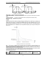
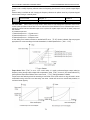
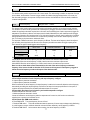
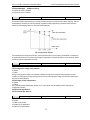
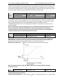
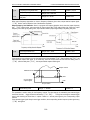
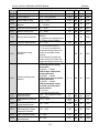
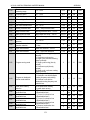
to protect over current occurs when load fluctuates suddenly. This parameter is used to define the acceleration
/deceleration time of frequency reducing.
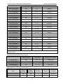
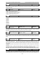
Acceleration time 2
Range: 0.1~6500.0s
Default: ※
F-25
Deceleration time 2
Range: 0.1~6500.0s
Default: ※
F-26
Acceleration time 3
Range: 0.1~6500.0s
Default: ※
F-27
Deceleration time 3
Range: 0.1~6500.0s
Default: ※
F-28
Acceleration time 4
Range: 0.1~6500.0s
Default: ※
F-29
Deceleration time 4
Range: 0.1~6500.0s
Default: ※
F-24
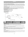
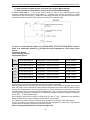
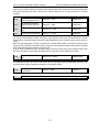
Acceleration time 2/3/4: When the[E-15]LED ten digit is set to 0, this refers to requirement time of accelerate
from 0.00Hz to maximum frequency [E-09]. When the[E-15]LED ten digit is set to 1, this refers to requirement time
of accelerate from 0.00Hz to motor rated frequency [H-53]. Refers to[E-15]parameters in detail.
Deceleration time 2/3/4: When the[E-15]LED ten digit is set to 0, this refers to requirement time of decelerates
from maximum frequency [E-09] to 0.00Hz. When the[E-15]LED ten digit is set to 1, this refers to the requirement
time of decelerates from motor rated frequency [H-53] to 0.00Hz. Refers to [E-15]parameters in detail.
Note: 1. It need to program the acceleration, deceleration time 2 during in UP/DW control ruing, refers to
[E-02] in detail.
2. It need to program the acceleration, deceleration time 2 during swing frequency control, refers to
[H-65] parameters in detail.
3. In program running mode, defines acceleration/deceleration time from 2 to 4 separately. Definition
of the acceleration /deceleration time as same as Accel./Decel. time 1. The Accel./Decel time are configured
by [H-35]~[H-49] parameters.
4. Acceleration/deceleration time of multi-step speed are programmed by [F-01]~[F-06]. The default
setting is acceleration/ deceleration time 1.
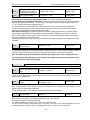
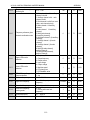
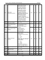
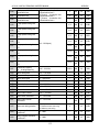
F-30
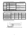
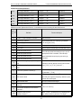
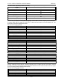
Relay output terminal
(TA,TB,TC)
Range: 0 ~ 21
Default: 1
F-31
Output terminal Y1
Range: 0 ~ 21
Default: 4
F-32
Output terminal Y2
Range: 0 ~ 21
Default: 7
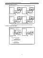
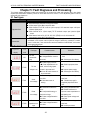
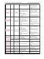
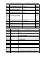
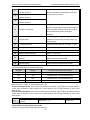
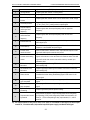
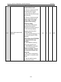
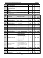
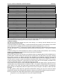
Setting
Definition
Function description
0
Zero frequency (
standby state)
Output signal when inverter is running and output frequency is 0 Hz,
1
Fault alarm 1
Output signal when fault alarms happening (including OU, OL, SC, OC,
OH, LUS, etc), enable output including fault reset auto period
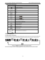
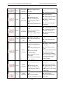
2
Fault alarm 2
Output signal when fault alarms happening (including OU,OL,SC,OC,
OH,LUS, etc), disable during fault auto reset period.
3
Frequency arriving
detection
When the output frequency is approaching or arriving to the frequency
given bias range, outputs valid signal, otherwise output invalid signal.
The bias range is determined by the parameter[F-33].
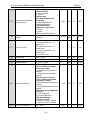
4
Frequency level
detection
When the output frequency over than frequency detecting level [F-34]
setting, output valid signal after [F-35] relay time setting. When the
output frequency lower than frequency detecting level, output a invalid
Value
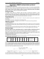
98