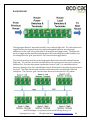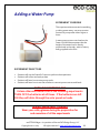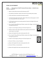
1
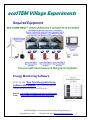
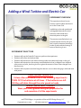
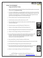
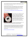
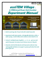
ecoSTEM Village
tm
A STEM-based Power Grid Simulator
Experiment Manual
• Build a working solar Power Grid with model house kits
• Experiment with solar panels, rechargeable batteries, LEDs, a
water pump, a wind turbine and a remote control electric car
• Connect multiple houses together…3…6...12…up to 15 and
watch the power increase as each house comes on the grid
• Simulate electrical blackouts and brownouts and learn how
rechargeable batteries can support a power grid when the main
power goes out
ecoSTEM Village tm is a product of the ecoCAD Design Group, LLC
Copyright 2012 -2014
All rights reserved www.ecoStemHouse.com
1
Important Advisory
These plans are presented in “as is” condition.
By using these plans you hold ecoCAD Design Group,
LLC and all members, investors, employees and
owners harmless from any damages arising from the
use of these plans including, but not limited to, the
resulting physical implementation of the plans and
any tests or experiments done with them.
In no case shall ecoCAD Design Group, LLC be liable
for any damages or injuries resulting from the use
and/or implementations of these plans and/or any
tests or experiments done with them.
These plans are not warranted for fitness for any
particular purpose.
Users of these plans assume all responsibility for their
safe and effective use.
By using these plans you agree to these terms.
ecoSTEM Village tm is a product of the ecoCAD Design Group, LLC
Copyright 2012 -2014
All rights reserved www.ecoStemHouse.com
2
ecoSTEM Village Experiments
Required Equipment
You can add more houses to the grid at anytime!
Energy Monitoring Software
Refer to the “Real Time Energy Monitoring
Software User Manual” for information on
installing and using the software…
Manual http://www.ecocaddesigngroup.com/downloads/
Video
http://www.ecocaddesigngroup.com/videos/
ecoSTEM Village tm is a product of the ecoCAD Design Group, LLC
Copyright 2012 -2014
All rights reserved www.ecoStemHouse.com
3
ecoSTEM Village Experiments
A collection of renewable energy experiments about
how Power Grids work and how to make them work better!
The Experiments
•
Each experiment is designed to take an average of one class period to perform.
Power Grid Simulation
•
•
•
Linking houses together into an electrical grid
Sharing power among houses
Simulating brownouts and blackouts
Rechargeable Battery Energy Storage
•
•
Smoothing out power surges with the house batteries
Rechargeable batteries as an “Energy Sponge”
Attach a Meter to Monitor the House Voltage
•
See how much voltage each house produces
Adding a Wind Turbine and Electric Car
•
•
See how much power you can generate from the wind to go into the houses
Do time trials on your electric car that’s charged from solar, wind or batteries.
Adding a Water Pump
•
See how high your water fountain can go with solar and wind energy
ecoSTEM Village tm is a product of the ecoCAD Design Group, LLC
Copyright 2012 -2014
All rights reserved www.ecoStemHouse.com
4
Power Grid Simulation
EXPERIMENT OVERVIEW
This experiment demonstrates how connecting
multiple houses together can form an electrical
power grid that shares power among the
houses. Brownout and blackout conditions are
simulated.
Indoors
Students will experiment with shining an
artificial light source on each of the house roof
solar panels to generate power to light LEDs
and spin ceiling fans.
Outdoors
The sun provides power for the solar panels
and works MUCH BETTER than using indoor
artificial light. Students will witness how
electricity produced by the solar panels is totally dependent on the amount of sun energy.
EXPERIMENT OBJECTIVES
•
•
•
•
•
Students will use the Scientific Process to perform the experiment.
Students will collect and analyze data.
Students will observe the photovoltaic effect of sunlight and artificial light to produce
electricity from solar panels.
Students will witness examples of Power Grid brownouts and blackouts
Students will learn how to use the switches to connect power sources and loads.
ALWAYS WEAR SAFETY GLASSES
Wear your safety glasses during the preparation for
and execution of all the experiments
ALWAYS WEAR SAFETY GLASSES
Wear your safety glasses during the preparation for
and execution of all the experiments
ecoSTEM Village tm is a product of the ecoCAD Design Group, LLC
Copyright 2012 -2014
All rights reserved www.ecoStemHouse.com
5
EQUIPMENT
•
•
•
•
•
ecoSTEM Village Houses (at least two connected together – more if possible)
Two, or more, 60 to 300 watt incandescent or halogen bulb lamps (don’t use a
fluorescent lamp – it will not generate enough illumination for this experiment)
You can also use the hand-held LED lights, but they don’t produce much power
Computer running the ecoCAD Real Time Energy Monitoring software
Printer (optional)
EXPERIMENT SETUP
•
•
•
•
•
Connect at least two (2) houses together with the supplied CAT5 cable from the Power
Out to the Power In connectors – connect more houses together this way, if available.
Start with all the switches of the house Control Panels OFF.
The CAT5 end of the USB Module should be connected to the Power-Out connector on
the last house OR the Power-In connector on the first house.
The other end of the USB Module should be connected with the supplied USB cable to
the computer with the ecoCAD Energy Monitoring Software running.
Setup the houses in an area where students can shine lights on the solar panels
(Indoors) or where the sunlight can reach the solar panels without any shade or other
obstructions (Outdoors).
DOING THE EXPERIMENT
Indoors
1. On the house connected to the USB Module, switch ON the House Roof solar panels
and the left and right LED groups.
2. Shine a light on the roof solar panels and view how the ceiling LEDs get brighter and
dimmer as the light is moved from side to side.
ecoSTEM Village tm is a product of the ecoCAD Design Group, LLC
Copyright 2012 -2014
All rights reserved www.ecoStemHouse.com
6
3. Notice the computer plots of the voltage, current and power generated as the
light is moved. Capture several images by clicking on the Screen Capture icon.
4. Switch ON the House Roof solar panels on the other house connected to the
first house. Don’t switch on anymore LEDs yet.
5. Shine another light on the solar panels of the second house and view how the
left and right LED groups on the first house get brighter.
6. Notice the computer plots of the voltage, current and power generated as the
light is moved. Capture several images by clicking on the Screen Capture icon.
7. Now switch ON the LEDs on the second house.
8. Notice how all the first house LEDs get dimmer. This is an example of a brownout
because the solar power has to be shared between both houses to light all the LEDs –
and there isn’t enough solar power to light all the LEDs to full brightness.
9. Finally, turn ON a fan on either house – the first or second – it doesn’t matter.
10. Notice that the fan doesn’t spin AND that the LEDs in both house go OUT.
This is an example of a blackout, because there is not enough power to supply
both the LEDs and the fan.
11. Capture a screen image by clicking on the Screen Capture icon.
12. You can repeat this experiment with more than two houses. Just hook up as
many houses as you have and see what happens.
Outdoors
Note: Make sure that the houses are in bright sun --- or if it’s overcast, that an even
amount of sunlight is shining on the solar panels of all the houses.
1. On the house connected to the USB Module, switch ON the House Roof solar
panels ((Input #3 & Input #4)) and the left and Right LED groups.
2. Clear the computer screen by clicking on the Trash can icon.
ecoSTEM Village tm is a product of the ecoCAD Design Group, LLC
Copyright 2012 -2014
All rights reserved www.ecoStemHouse.com
7
3. With just the solar panels and LEDs of the first house ON, notice the computer
plots of the voltage, current and power. Capture an image by clicking on the
Screen Capture icon.
4. Next, switch ON the House Roof solar panels on the second house. Don’t
switch on anymore LEDs yet.
5. Notice that the LEDs on the first house get brighter. You can confirm this by looking at
the voltage, current and power on the computer plots; they should be higher. Capture
an image by clicking on the Screen Capture icon.
6. Now switch ON the LEDs on the second house.
7. Notice that the first house LEDs “may” get dimmer. This is because the solar power has
to be shared between both houses to light all the LEDs, but the solar energy from the
sun may be strong enough to keep the LEDs at the same brightness level.
8. Turn ON a fan on either house – the first or second – it doesn’t matter.
9. Notice that the fan being ON causes the LEDs to get slightly dimmer. If the sun is very
bright you may have to shade some of the solar panels to see this. This is an example of
a brownout because the solar power has to be shared between both houses to light all
the LEDs and run the fan – and there may not be enough solar power to do this –
especially if the day is overcast.
10. You can confirm this by looking at the voltage, current and power on the
computer plots; they should be lower than before. Capture an image by
clicking on the Screen Capture icon.
11. Next, switch on the second fan and notice that the first fan runs slower and
that the LEDs get even dimmer. If the sun is very bright you may have to shade some
of the solar panels to see this. This is another example of a brownout because the solar
power has to be shared between both houses to light all the LEDs and run the fans and
there may not be enough solar power to do this.
12. Finally, shade the solar panels on both houses until the LEDs go OUT and the fans
either run very slowly or not at all. This is an example of a blackout, because
there is not enough power to supply the LEDs and the fan.
13. Capture a screen image by clicking on the Screen Capture icon.
ecoSTEM Village tm is a product of the ecoCAD Design Group, LLC
Copyright 2012 -2014
All rights reserved www.ecoStemHouse.com
8
STUDENT EXERCISES
Power Grid Simulation
1. In this experiment how would you describe a “brownout”?
2. In this experiment how you would describe a “blackout”?
3. How is a real brownout and blackout caused?
4. What can you do to help prevent and recover from a real brownout or blackout?
ecoSTEM Village tm is a product of the ecoCAD Design Group, LLC
Copyright 2012 -2014
All rights reserved www.ecoStemHouse.com
9
TEACHER NOTES - ANALYZING THE RESULTS
Power Grid Simulation
The power grid formed by the ecoSTEM Village houses simulates actual brownout and
blackout conditions when the electrical power is insufficient in terms of running the home
appliances like LEDs and a fan in this case.
The word “brownout” describes an electrical condition where the power is not completely
“out”, but when the voltage and currents being supplied by the power plants (the solar panels)
are not enough to support the loads (the LEDs and fans). In a brownout the appliances like
motors and fans run slower and lights are dimmer than normal. This condition remains until
sufficient power from the power plant is restored.
The word “blackout” is worse than a brownout because all electrical power is OFF – or is so low
that no appliances can operate at all. Blackouts normally occur when the power grid is
strained to the point that circuit breakers (at the local and remote power plants) “trip” and cut
off power to homes and other facilities that use power. Blackouts normally occur during
inclement weather when it’s hot and people are using air conditioners and other appliances to
stay cool.
An air conditioner is basically a motor-pump that uses a lot of electricity. With many of them
on the grid at the same time the power plant can’t keep up with their combined electrical
demand, so the main circuit breakers trip and interrupt the power going to the grid. Power is
normally restored within a few minutes to a few hours after the power plants either 1) are able
to make more power to supply to the grid or 2) bring on spare power from nearby power plants
that have more capacity.
Preventing brownouts and blackouts are fairly simple.
Just make sure to use less “power hungry” appliances. Turn off air conditioners or set them so
that they don’t turn ON as much when it warms up, which causes the unit to use more power.
Setting an air conditioner at 78 degrees instead of 68 degrees will help prevent a lot of
brownouts and blackouts.
Also during a brownout of blackout, turn off all unnecessary appliances like fans, lights,
washers and dryers, computers, televisions, computers, etc. This will reduce the electrical load
on the power plant and will allow power to be restored much sooner.
ecoSTEM Village tm is a product of the ecoCAD Design Group, LLC
Copyright 2012 -2014
All rights reserved www.ecoStemHouse.com
10
Battery Energy Storage
EXPERIMENT OVERVIEW
The experiment explains how solar power can be stored
in rechargeable batteries.
It also demonstrates how a battery “smoothes out” the
variations in normal solar panel energy and effectively
acts as an “energy sponge” that stores intermittent
power; i.e., power that isn’t constant.
The experiment goes on to demonstrates why battery
energy storage is important for a normal power grid.
EXPERIMENT OBJECTIVES
•
•
•
•
•
Students will use the Scientific Process to perform the experiment.
Students will collect and analyze data.
Students will observe the photovoltaic effect of sunlight and artificial light to produce
electricity from solar panels.
Students will learn how rechargeable batteries store solar power and why they are
important to the Power Grid concept.
Students will learn how to use the switches to connect power sources and loads.
TURN THE BATTERIES OFF
Unless otherwise asked to do in the following experiments
TURN OFF the batteries at all times. If the batteries are left
ON they will drain through the solar panels or loads.
ALWAYS WEAR SAFETY GLASSES
Wear your safety glasses during the preparation for
and execution of all the experiments
ecoSTEM Village tm is a product of the ecoCAD Design Group, LLC
Copyright 2012 -2014
All rights reserved www.ecoStemHouse.com
11
EQUIPMENT
•
•
•
•
•
ecoSTEM Village Houses (at least two connected together – more if possible)
Two, or more, 60 to 300 watt incandescent or halogen bulb lamps (don’t use a
fluorescent lamp – it will not generate enough illumination for this experiment)
You can also use the hand-held LED lights, but they don’t produce much power
Computer running the ecoCAD Real Time Energy Monitoring software
Printer (optional)
EXPERIMENT SETUP
•
•
•
•
•
Connect at least two (2) houses together with the supplied CAT5 cable from the Power
Out to the Power In connectors – connect more houses together this way, if available.
Start with all the switches of the house Control Panels OFF.
The CAT5 end of the USB Module should be connected to the Power-Out connector on
the last house OR the Power-In connector on the first house.
The other end of the USB Module should be connected with the supplied USB cable to
the computer with the ecoCAD Energy Monitoring Software running.
Setup the houses in an area where students can shine lights on the solar panels
(Indoors) or where the sunlight can reach the solar panels without any shade or other
obstructions (Outdoors).
DOING THE EXPERIMENT
1. On each house switch the Battery switch ON along with both LEDs and Fan ON. The
purpose is to drain the batteries for the following experiment.
2. Allow the batteries to discharge into the LEDs and fans.
3. When the batteries are fully drained and no LEDs are ON and the Fan isn’t spinning,
then set ALL the switches on all the houses to OFF.
ecoSTEM Village tm is a product of the ecoCAD Design Group, LLC
Copyright 2012 -2014
All rights reserved www.ecoStemHouse.com
12
Indoors
NOTE:
Do the following for each house.
1. Set both the solar panel switches ON.
2. Set both the LED switches ON.
3. Set the Battery and Fan switches OFF.
4. We are now about to power the LEDs from just the solar panels.
5. Shine a light on the solar panels and watch how the LEDs go from bright to dim as
the light moves across the solar panels.
6. Now set both the LED switches and all other switches on the right-side of the board
to OFF on all houses.
7. Set the Battery and both solar panel switches ON.
8. We are now about to charge the batteries without any loads like LEDs and Fans on
them.
9. Shine the light directly on the solar panels for about 10 minutes. This should be
enough time to charge the battery a little.
10. After 10 minutes set both the solar panels switches OFF, but leave the Battery
switch ON.
11. Monitor the battery voltage on the Energy Monitoring software.
12. The batteries must be charged to at least 3 volts for the following part of the
experiment to work. If the voltage is less than 3 volts, keep shining the lights on the
solar panels until the voltage is 3 volts or greater.
13. Set one of the LED switches ON. Notice that the left two ceiling LEDs
illuminate.
14. Capture a screen image by clicking on the Screen Capture icon.
15. Set the second LED switch ON. Notice that the right two ceiling LEDs
illuminate. The LEDs may be dimmer since they are using more of the
battery’s available power.
16. Capture a screen image by clicking on the Screen Capture icon.
ecoSTEM Village tm is a product of the ecoCAD Design Group, LLC
Copyright 2012 -2014
All rights reserved www.ecoStemHouse.com
13
17. Set the Fan switch ON.
18. Notice the extra power being used on the software plot. Also, the LEDs may go
OUT when the Fan is ON. This is normal for a low battery charge.
19. Watch the voltage, current and power plots on the Energy Monitor software and
notice how long it takes for the battery to drain to nearly zero volts.
Outdoors
NOTE:
Do the following for each house.
1. Set both the solar panel switches ON.
2. Set both the LED switches ON.
3. Set the Battery and Fan switches OFF.
4. We are now about to power the LEDs from just the solar panels.
5. Expose the solar panels to direct sun.
6. With your hands or a sheet of paper, shade the solar panels so that the LEDs go
from bright to dim as the solar panels are shaded.
7. Now set both the LED switches OFF.
8. Set the Batter and both solar panel switches ON.
9. We are now about to charge the batteries without any loads like LEDs and Fans on
them.
10. Allow the solar panels to charge for about 5 minutes. This should be enough time to
charge the battery a little.
11. After 5 minutes set both the solar panel switches OFF, but leave the Battery switch
ON.
12. Monitor the battery voltage on the Energy Monitoring software.
13. The batteries must be charged up to at least 3 volts for the following part of the
experiment to work. If the voltage is less than 3 volts continue to charge the
batteries until the voltage reaches 3 volts or more.
ecoSTEM Village tm is a product of the ecoCAD Design Group, LLC
Copyright 2012 -2014
All rights reserved www.ecoStemHouse.com
14
14. Set one of the LED switches ON. Notice that the left two ceiling LEDs illuminate.
15. Capture a screen image by clicking on the Screen Capture icon.
16. Set the second LED switch ON. Notice that the right two ceiling LEDs
illuminate. The LEDs may be dimmer since they are using more of the
battery’s available power.
17. Capture a screen image by clicking on the Screen Capture icon.
18. Set the Fan switch ON.
19. Notice the extra power being used on the software plots. Also, the LEDs
may grow dimmer and go OFF.
20. Watch the voltage, current and power plots on the Energy Monitor software and
notice how long it takes for the battery to drain to zero volts.
ecoSTEM Village tm is a product of the ecoCAD Design Group, LLC
Copyright 2012 -2014
All rights reserved www.ecoStemHouse.com
15
STUDENT EXERCISES
Battery Energy Storage
1. How do batteries “smooth out” the power from the solar panels?
2. Why could the batteries in this experiment be called an “energy sponge”?
3. If you had real solar panels on your house or apartment to create electrical power for
your appliances like TVs and computers, why would you also want to have them charge
up your house batteries?
ecoSTEM Village tm is a product of the ecoCAD Design Group, LLC
Copyright 2012 -2014
All rights reserved www.ecoStemHouse.com
16
TEACHER NOTES - ANALYZING THE RESULTS
Battery Energy Storage
A rechargeable battery is a device that stores electrical power for later use. Once its power is
used up it can be replenished (recharged) over and over again.
An important rechargeable battery characteristic is that it can receive different levels of power
(a lot or a little) at different times and still accumulate these bursts of instantaneous power into
“an electrical reservoir” where electrical power can be drawn upon as needed.
Think of a battery as an “energy sponge”. A sponge can absorb lots of water at one time or it
can absorb it drop by drop. The sponge will fill with water at a rate depending on the water
given to it. Either way, once it’s saturated, it can give that water back by squeezing it out –
again, a little at a time or a lot.
A rechargeable battery absorbs electrons instead of water, but the principle is the same. A
battery can absorb electrons a little or a lot at one time. That’s what this experiment describes.
By shining the light on the solar panels the battery received more electrons when the light was
brightly shining as compared to when the light was not applied directly to the solar panels. But
it still stored up all the electrons it was given and then released them back into the LEDs and
fans when they were turned ON. Once the electrons were “used up” the battery went “dead”.
For a real solar panel installation like on a house, having batteries to smooth out the power and
provide power when the sun isn’t shining is very important. For example, most homes use
their power in the early morning and evening when the sun isn’t shining. If the home also had a
battery backup system installed along with the solar panels, then the appliances could use
power from the batteries in the morning and evening. The batteries would recharge during the
day when most of the appliances are not running.
This is why the ecoSTEM Village has rechargeable batteries -to demonstrate this important
concept of energy storage and reuse when the energy is actually needed – and not just when
it’s being produced by sunlight. Plus, with a solar-powered battery-backup system, your house
can operate electrical appliances even during a brownout or blackout…for hours, days and
even weeks on end.
ecoSTEM Village tm is a product of the ecoCAD Design Group, LLC
Copyright 2012 -2014
All rights reserved www.ecoStemHouse.com
17
Attach a Meter to Monitor House Voltage
EXPERIMENT OVERVIEW
This experiment shows how to connect
a voltmeter to the Aggregator Board’s
terminals to monitor the house voltage.
As connected here, the voltmeter
shows the voltage produced by “this
house only” and not the combined
voltage produced by all the houses that
are connected together with cables.
This experiment also shows how to
connect the voltmeter to measure the
total grid voltage of all the houses.
EXPERIMENT OBJECTIVES
Students will use the Scientific Process to perform the experiment.
Students will collect and analyze data.
Students will understand how to setup and use a conventional voltmeter to measure the
DC voltage produced by the house batteries and solar panels.
• Students will witness how the batteries and solar panels of each house contribute to the
combined voltage of the entire “house grid”.
• Students will learn how to use the switches to connect power sources and loads.
•
•
•
TURN THE BATTERIES OFF
Unless otherwise asked to do in the following experiments
TURN OFF the batteries at all times. If the batteries are left
ON they will drain through the solar panels or loads.
ALWAYS WEAR SAFETY GLASSES
Wear your safety glasses during the preparation for
and execution of all the experiments
ecoSTEM Village tm is a product of the ecoCAD Design Group, LLC
Copyright 2012 -2014
All rights reserved www.ecoStemHouse.com
18
EQUIPMENT
•
•
•
•
ecoSTEM Village Houses (at least two connected together – more if possible)
Two, or more, 60 to 300 watt incandescent or halogen bulb lamps (don’t use a
fluorescent lamp – it will not generate enough illumination for this experiment)
You can also use the hand-held LED lights, but they don’t produce much power
Supplied voltmeter
EXPERIMENT SETUP
•
•
•
•
•
•
•
Set the voltmeter dial to “20 DCV”, which means it will measure up to 20 volts DC. Our
batteries and solar panels normally don’t go much over 6 volts so this is the best
setting. The example photo above shows a battery voltage 0f 3.91 volts.
Attach the voltmeter probes to the left-most push terminals labeled ACC IN – the Red
lead on the left terminal and the Black lead on the right terminal as shown above. Do
this for each house.
Set the left-most toggle switch ON. This allows the solar panel and battery voltages to
be read by the meter – once the toggle switch is turned ON.
Set the other toggle switches to OFF for the moment.
Connect at least two (2) houses together with the supplied CAT5 cable from the Power
Out to the Power In connectors – connect more houses together this way, if available.
Setup the houses in an area where students can shine lights on the solar panels
(Indoors) or where the sunlight can reach the solar panels without any shade or other
obstructions (Outdoors).
The computer is optional for this experiment.
ecoSTEM Village tm is a product of the ecoCAD Design Group, LLC
Copyright 2012 -2014
All rights reserved www.ecoStemHouse.com
19
BACKGROUND
The Aggregator Board is “electrically divided” into a Left and Right side. The Left side has four
toggle switches and terminals that control the rechargeable batteries and solar panel
attachment to the “grid” along with the ACC IN terminals and toggle switch. The Right side
has four toggle switches and terminals that allow LEDs and ceiling fans (called Loads) to use
the voltage from the “grid” plus the ACC OUT terminals and toggle switch.
The Left side terminal-switches on each Aggregator Board are electrically isolated from the
Right side. The Left four terminal-switches connect the input power to the “grid” as they are
switched ON. Once this input power reaches the common “grid”, it is combined with the
electricity flowing in from the Left and Right sides of all the other houses that are connected to
the “grid”. The Right side terminal-switches are all connected to the loads like LEDs and
ceiling fans. The common “grid” connects from house to house with the CAT5 cables.
ecoSTEM Village tm is a product of the ecoCAD Design Group, LLC
Copyright 2012 -2014
All rights reserved www.ecoStemHouse.com
20
DOING THE EXPERIMENT
Indoors or Outdoors
1. Make sure that the voltmeter is connected as described in the Experiment Setup
on each of the houses.
2. Verify that all other switches on ALL the houses are OFF, except the one attached
to the ACC IN terminals – the one connected to the voltmeter.
3. On the first house (any house will do) set both the solar panel switches ON and
shine some light on both the solar panels.
4. Verify that the meter reading changes with the light levels.
5. Again on the first house leave the solar panel switches ON and then set the Battery
switch ON and verify that the voltmeter reading stays steady even if light is shining
on the solar panels.
Note – If you’re outdoors, try shading the solar panels and notice how little, if any, the
meter voltage changes with the Battery switch ON.
6. On the first house set both the solar panel and Battery switches to OFF and verify
that the voltmeter reads 00.00 or nearly so.
7. On any of the other houses connected to the grid…set the Battery switch ON.
8. Notice that the first house voltmeter does not show much, if any, voltage reading.
This is because it is electrically isolated from the other houses.
9. Repeat the above steps for each of the other houses that are attached together.
This demonstrates how each house’s input power is electrically isolated from the
others.
10. On the first house move the voltmeter leads from the ACC IN (left-most) terminals
to the ACC OUT (right-most) terminals. Observe the Red-Black polarity of the
hookup.
11. Set the ACC IN toggle switch OFF and set the ACC OUT toggle switch ON. This will
allow the voltmeter to monitor the “grid” voltage that is common to all the houses.
12. Next, experiment with switching the Solar and Battery switches ON and OFF on the
other houses to see how the voltmeters react.
ecoSTEM Village tm is a product of the ecoCAD Design Group, LLC
Copyright 2012 -2014
All rights reserved www.ecoStemHouse.com
21
STUDENT EXERCISES
Let Students Experiment
The idea behind having voltmeters connected to the ACC IN terminals is to see which house
can produce the most voltage. Have the students compete with one another to see which
house produces the most voltage WITHOUT THE BATTERY ON using only the solar panels.
TEACHER NOTES - ANALYZING THE RESULTS
Why don’t the solar panel voltages affect the battery voltage?
Solar panels – by themselves with nothing else connected to them – can produce more voltage
than the rechargeable battery pack even with artificial light.
But when our solar panels are connected to the batteries (by switching on the solar panel AND
the battery switches), the battery acts as a “current reservoir” and reduces the solar panel
voltage down to whatever the battery voltage is at any given time. That’s basically why the
solar panels have little or no effect on the overall voltage readings when the batteries are in the
circuit.
However….
If the solar panels were larger
OR
If the solar panels on the houses are exposed to direct sunlight, the results will be different with
the solar panel voltage becoming more than the battery voltage.
In either case it’s all about current more than voltage. With direct sunlight more current is
delivered from the solar panels thus they become as “strong” as the batteries in terms of
maintaining their individual voltages.
You and the students can learn more about voltage, current and resistance – the three basic
components of electricity – from the reference at the end of this manual called “How
Electricity Works”.
ecoSTEM Village tm is a product of the ecoCAD Design Group, LLC
Copyright 2012 -2014
All rights reserved www.ecoStemHouse.com
22
Adding a Wind Turbine and Electric Car
EXPERIMENT OVERVIEW
This experiment shows how to
connect a wind turbine and electric
car to the Power Grid.
In addition to the solar panels and
rechargeable batteries the wind
turbine is used to add more
electrical power to the grid.
The remote controlled electric car
provides another load on the grid
and is used to measure the energy
intake of solar and wind energy in
terms of how long it runs.
EXPERIMENT OBJECTIVES
•
•
•
•
•
Students will use the Scientific Process to perform the experiment.
Students will collect and analyze data.
Students will witness how the wind turbine provides extra electrical power to the grid.
Students will witness how the remote controlled electrical car is charged from wind and
solar power and, also, how long it will run given the amount of time it was charged from
these sources.
Students will compete to see how long their electric car runs after charging it with solar and
wind power.
TURN THE BATTERIES OFF
Unless otherwise asked to do in the following experiments
TURN OFF the batteries at all times. If the batteries are left
ON they will drain through the solar panels or loads.
ALWAYS WEAR SAFETY GLASSES
Wear your safety glasses during the preparation for
and execution of all the experiments
ecoSTEM Village tm is a product of the ecoCAD Design Group, LLC
Copyright 2012 -2014
All rights reserved www.ecoStemHouse.com
23
EQUIPMENT
•
•
•
•
•
•
•
•
ecoSTEM Village Houses (at least two connected together – more if possible)
Two, or more, 60 to 300 watt incandescent or halogen bulb lamps (don’t use a
fluorescent lamp – it will not generate enough illumination for this experiment)
You can also use the hand-held LED lights, but they don’t produce much power
Computer running the ecoCAD Real Time Energy Monitoring software
Printer (optional)
Wind turbine and connecting cable
Remote Control docking station, remote control unit, electric car and connecting cable
Table fan (for the wind turbine)
EXPERIMENT SETUP
•
•
Attach the Wind Turbine connecting cable wires to the ACC IN (left-most) terminals as
shown above with the white wire on the left terminal and the braded wire on the right.
Connect the other end of the cable to the underside of the wind turbine.
Attach the Remote Control docking station cable wires to the ACC OUT (right-most)
terminals as shown with the white wire on the left and the braded wire on the right.
Connect the other end of the cable to the front of the docking station as shown.
ecoSTEM Village tm is a product of the ecoCAD Design Group, LLC
Copyright 2012 -2014
All rights reserved www.ecoStemHouse.com
24
DOING THE EXPERIMENT
using only the Wind Turbine
1. Make sure that the wind turbine and the Remote Control docking station are connected
as described in the Experiment Setup.
2. If you have multiple houses connected together, attach the wind turbine to the ACC IN
terminals on the far left house and the Remote Control docking station to the ACC OUT
terminals on the far right house. This will allow the wind turbine to power the entire
grid of houses and charge the electric car at the end of the grid.
3. Set the switches that are underneath the(wind turbine to ON.
4. Set all the other switches on all the other houses to OFF.
5. Place the table fan facing the wind turbine and turn the fan ON to make the
wind turbine blades spin.
6. Clear the computer screen by clicking on the Trash can icon.
7. Capture a screen image by clicking on the Screen Capture icon.
8. Note the voltage generated by the wind turbine on the computer plots.
9. Capture a screen image by clicking on the Screen Capture icon.
10. On one of the houses set both the LED switches ON and verify that the LEDs
illuminate. If they don’t illuminate then adjust the fan speed and/or fan
position to make the wind turbine generate more electricity. It takes a
minimum of 3.0 volts to illuminate the LEDs.
11. Next, switch ON ALL of the LED switches on all the houses.
12. Verify that all the LEDs are illuminated using only the power from the wind turbine.
13. Now switch ON a ceiling fan on any house and verify that it spins.
14. Also verify that all the LEDs are still illuminated but may be dimmer due to the
fact that most of the wind turbine’s power is going into the ceiling fan.
15. Capture a screen image by clicking on the Screen Capture icon.
ecoSTEM Village tm is a product of the ecoCAD Design Group, LLC
Copyright 2012 -2014
All rights reserved www.ecoStemHouse.com
25
DOING THE EXPERIMENT
using both the Wind Turbine and Electric Car
16. Set all the LED and ceiling fan switches to OFF.
17. Turn the fan OFF so that the wind turbine blades do not spin.
18. Set the switches that are underneath the wind turbine and Remote Control terminals to
ON. Turn all other switches OFF. This essentially attaches the wind turbine to the
Remote Control docking station.
Note – the next part of this experiment deals with charging the electric car using only the
power from the wind turbine.
19. Set the small switch on the bottom of the electric car to ON.
20. Attach the electric car to the Remote Control docking station by pushing its body onto
the protruding terminal on the docking station.
21. Turn the fan ON so that the wind turbine blades begin to spin.
22. Observe the flashing RED light on the Remote Control docking station. This indicates
that the electric car is being charged.
23. Allow about 3 to 4 minutes for the electric car to charge.
24. The RED flashing light will go OFF and the GREEN flashing light will go ON when
charging is complete.
25. Turn the fan OFF so the wind turbine blades do not spin.
26. Remove the electric car from the Remote Control docking station and use the circular
remote control unit to run the car.
27. Let the car run until it stops. This just makes sure that things are working.
28. Now repeat steps 19 through 24, but use a watch or electronic timer to time how long it
takes to charge the car (flashing RED to flashing GREEN light on the docking station).
29. Note exactly how long it takes to charge the car.
30. Once again, discharge the car’s internal power source by running it until it stops.
ecoSTEM Village tm is a product of the ecoCAD Design Group, LLC
Copyright 2012 -2014
All rights reserved www.ecoStemHouse.com
26
DOING THE EXPERIMENT
using both the Wind Turbine and Electric Car and other loads
31. Once again turn the fan ON so that the wind turbine blades begin to spin.
32. Observe the flashing RED light on the Remote Control docking station. This indicates
that the electric car is being charged.
33. Start timing the car charging event now.
34. Next, turn on a house ceiling fan. You may notice that the wind turbine blades spin
slower when this happens…more about this later.
35. The RED flashing light will go OFF and the GREEN flashing light will go ON when
charging is complete.
36. Note the time when this happens.
37. Turn the fan OFF so the wind turbine blades do not spin.
38. Now compare the time in step 29 to this time. It’s predicted to be a longer time, but
your results may not bear this out.
39. Remove the electric car from the Remote Control docking station and use the circular
remote control unit to run the car.
40. Let the car run until it stops.
41. Repeat steps 31 through 40 but this time turn ON more ceiling fans and LEDs to add
more loads to the power grid.
ecoSTEM Village tm is a product of the ecoCAD Design Group, LLC
Copyright 2012 -2014
All rights reserved www.ecoStemHouse.com
27
STUDENT EXERCISES
Adding a Wind Turbine and Electric Car
Explain why the wind turbine blades slowed down when the ceiling fan was turned ON.
Explain why it took longer to charge the electric car when more and more fans were turned
ON.
ecoSTEM Village tm is a product of the ecoCAD Design Group, LLC
Copyright 2012 -2014
All rights reserved www.ecoStemHouse.com
28
TEACHER NOTES - ANALYZING THE RESULTS
Adding a Wind Turbine and Electric Car
While this experiment seemed simple enough to perform, there’s a lot to explain about what
happened. Let’s look at two of the fundamental questions:
1. Why did the wind turbine blades slow down when one, or more, ceiling fans were
turned ON and
2. Why did it take longer to charge the electric car when the fans were ON?
For both questions the house ceiling fans present a heaver load on the only power source
available at the time – namely, the wind turbine.
At the same time the wind turbine had only one fundamental power source – the table fan. So
if more power is required from the wind turbine then the wind from the table fan needs to
increase. But in our experiment it didn’t; it stayed at one speed so something had to give, and
what gave is the wind turbine blades slowed down.
Have the students’ think of it this way. It’s like riding a bicycle up a hill. As the hill gets steeper
the bicycle slows down accordingly. Why? Because the only power source for the bicycle is the
rider him or herself.
The same is true for the wind turbine. The only power source is the table fan and as more loads
are added (fans) the “virtual hill” gets steeper and thus the spinning blades slow down.
As for the extra time it took to charge the electric car, this is due to the fact that the ceiling
fans drained away considerable power from the grid so it takes longer to fully charge the
electric car – at least this is what’s supposed to happen. Your results may vary in so far as the
Remote Control docking station may, or may not, measure the total amount of power needed
to charge the internal super capacitor in the electric car, but this is what’s supposed to occur.
Again, this is an interesting experiment to perform so give it a chance to work by repeating it
several times to see if the results match this explanation.
ecoSTEM Village tm is a product of the ecoCAD Design Group, LLC
Copyright 2012 -2014
All rights reserved www.ecoStemHouse.com
29
Adding a Water Pump
EXPERIMENT OVERVIEW
This experiment demonstrates how adding,
or taking power away, can cause a water
fountain to pump water either higher or
lower.
A water pump puts an extra load on the
Power Grid and demonstrates that the
height of the water level is directly
proportional to the solar, wind or battery
energy applied to the Grid.
EXPERIMENT OBJECTIVES
•
•
•
•
Students will use the Scientific Process to perform the experiment.
Students will collect and analyze data.
Students will learn how a water pump works.
Students will learn how to use the switches to connect power sources and loads.
TURN THE BATTERIES OFF
Unless otherwise asked to do in the following experiments
TURN OFF the batteries at all times. If the batteries are left
ON they will drain through the solar panels or loads.
ALWAYS WEAR SAFETY GLASSES
Wear your safety glasses during the preparation for
and execution of all the experiments
ecoSTEM Village tm is a product of the ecoCAD Design Group, LLC
Copyright 2012 -2014
All rights reserved www.ecoStemHouse.com
30
EQUIPMENT
•
•
•
•
•
ecoSTEM Village Houses (at least two connected together – more if possible)
Two, or more, 60 to 300 watt incandescent or halogen bulb lamps (don’t use a
fluorescent lamp – it will not generate enough illumination for this experiment)
Computer running the ecoCAD Real Time Energy Monitoring software
Water pump attached to a water source and measuring tube
Printer (optional)
EXPERIMENT SETUP
•
•
•
•
•
•
Connect at least two (2) houses together with the supplied CAT5 cable from Power Out
to Power In – connect more houses together this way, if available.
To start, all the switches of the house Control Panels should be OFF.
The CAT5 end of the USB Module should be connected to either the Power-Out
connector on the last house or the Power-In connector on the first house.
The other end of the USB Module should be connected with the supplied USB cable to
the computer with the ecoCAD Energy Monitoring Software running.
Setup the houses in an area where students can shine lights on the solar panels
(Indoors) or where the sunlight can reach the solar panels without any shade or other
obstructions (Outdoors).
Attach the water pump wires to the right-most house on the ACC-OUT push terminals.
Make sure to observe polarity; white is positive, black is negative.
ecoSTEM Village tm is a product of the ecoCAD Design Group, LLC
Copyright 2012 -2014
All rights reserved www.ecoStemHouse.com
31
DOING THE EXPERIMENT
NOTE:
This experiment CANNOT be done effectively indoors. It should be done
outdoors in bright sun.
1. Make sure that all the switches on all the houses are OFF.
2. Also make sure that there is water in the reservoir for the water pump to pump.
3. Set the switch that’s connected to the water pump ON.
4. Set both the solar panel switches ON. Begin with one house and progress to switch
more solar panels ON for the other houses.
5. Verify that the water pump is pumping water and measure the height of the water
stream with a ruler.
6. Also, using the Energy Monitoring Software, measure the voltage, current and power
flowing through the Grid.
7. Capture a screen image by clicking on the Screen Capture icon.
8. With your hand or other object shade the solar panels and notice that the
water stream is not as high.
9. Measure the height of the water stream again with a ruler.
10. Also, using the Energy Monitoring Software, measure the voltage, current and power
flowing through the Grid
11. Capture a screen image by clicking on the Screen Capture icon.
12. Now turn ON one, or more, ceiling fans.
13. Measure the height of the water stream again with a ruler.
14. Now turn ON one, or more, batteries.
15. Measure the height of the water stream again with a ruler.
ecoSTEM Village tm is a product of the ecoCAD Design Group, LLC
Copyright 2012 -2014
All rights reserved www.ecoStemHouse.com
32
STUDENT EXERCISES
Adding a Water Pump
1. Why do think the water pump pumped less water when the fans were turned ON?
2. Did turning on the batteries make the water go higher, lower or stay about the same
height? Explain why you think this happened.
ecoSTEM Village tm is a product of the ecoCAD Design Group, LLC
Copyright 2012 -2014
All rights reserved www.ecoStemHouse.com
33
TEACHER NOTES - ANALYZING THE RESULTS
Adding a Water Pump
The water pump is really just another motor like the fan. When a ceiling fan (or fans) is turned
ON they divert the available power to themselves. Therefore, the water pump will pump less
water because it has less power to apply to itself.
Adding the batteries to the power grid provides a more consistent level of power to all the
loads like the ceiling fans and water pump. But because the battery voltage is set at a certain
maximum level (about 4 volts maximum) it may not cause the water pump to pump water as
high as when only the solar panels are used for power. Again, because the battery voltage is
less than the solar panel voltage.
There is another interesting facet to this “solar panel – battery” mix.
Even though a solar panel can produce more voltage than the batteries (6 volts for the solar
panel versus 4 volts for the batteries), the total grid voltage will rarely, if ever, exceed the
battery voltage. This is because the batteries act as an “energy sink” and draw down the
voltage of the solar panels to match their own. Further this is because the batteries have a
greater electrical mass as compared with the solar panels. So even though the batteries will
run the pump they may not deliver as much voltage to it thus making the water level lower.
ecoSTEM Village tm is a product of the ecoCAD Design Group, LLC
Copyright 2012 -2014
All rights reserved www.ecoStemHouse.com
34
ecoSTEM Village
tm
A STEM-based Power Grid Simulator
Background Information
• How Electricity Works
• Solar Panel Fundamentals
ecoSTEM Village tm is a product of the ecoCAD Design Group, LLC
Copyright 2012 -2014
All rights reserved www.ecoStemHouse.com
35
How Electricity Works
ecoSTEM Village tm is a product of the ecoCAD Design Group, LLC
Copyright 2012 -2014
All rights reserved www.ecoStemHouse.com
36
How Electricity Works
The following is important background on the basics of electricity like voltage, current,
power and resistance as well as series and parallel circuits, AC and DC and information
on important devices like LEDs and fuel cells. Each topic is presented as a question…
What is Voltage?
Voltage is to electricity as pressure is to water; both
are forces that move things.
Voltage is the force that moves electrons through a
circuit; the greater the voltage the greater the force
of electron movement. Voltage is generated by
creating a “potential difference” between positive
and negative elements of the device generating it.
Like water, the higher the voltage, the more force it
exerts. Water falling from a height uses gravity to create force; the higher the water
falls (its potential difference), the more force or pressure it creates. Unlike water,
however, voltage is not created by gravity but by chemical, optical, or magnetic forces.
Batteries use chemicals to generate voltage while some fuel cells use electrons in
hydrogen gas to create voltage. Solar panels use optical means to capture the sun’s
photons and wind turbines use rotating magnets that are very close to coils of wire that
generate voltage based on the magnetic field created by the magnet’s rotation.
Voltage is measured in units called volts
What is Current?
Electrical current is to electricity as the “volume” (not pressure) of water is to water
flow. A fire hose can carry more water compared with a clogged shower head. So too
can lager wires carry more current as compared with smaller wires.
Electrical current carries electrons along a
path (called a circuit) like water carries
water molecules through a hose. More
electrons mean more current flow.
ecoSTEM Village tm is a product of the ecoCAD Design Group, LLC
Copyright 2012 -2014
All rights reserved www.ecoStemHouse.com
37
Water normally flows from upstream to downstream using gravity as a force. Electrical
current normally flows from positive (+) to negative (-), which is called direct current or
DC for short, but gravity is not involved.
Unlike water, electrical current can flow in either direction – positive to negative and
negative to positive. The latter is usually called alternating current, or AC, since the
current switches (alternates) between positive and negative directions. Electrical
current produced by batteries are DC while electrical current coming out of the wall
socket is AC. Both have their applications in electronic circuits.
Current is measured in units called amperes or amps and sometimes milliamps.
What is Resistance?
Electrical resistance can be compared to a corroded
water pipe. If the water pipe is wide and clear of
corrosion the resistance is minimal because more
water can flow. If a water pipe is narrow and
corroded, resistance is greater since water cannot
flow because of the internal barriers to it. A garden
hose has a higher resistance to water flow as
compared with a fire hose since, for a given amount
of water pressure (voltage in electrical terms), less
water (or current in electrical terms) can flow
through the garden hose as compared with a fire
hose.
Like the larger fire hose, larger wires can carry more
electrical current as compared with smaller wires. In electrical circuit boards,
components called resistors are inserted in the circuit to limit current flow.
The resistance to the flow of electrons depends on the type and size of the materials
used. While water flowing in a pipe does not generally produce heat by itself, electrical
resistive materials produce varying degrees of heat created by the flow of electrons
through the material. Heat is generally considered wasted energy (as in a hot light
bulb) but not always, as in a toaster or hair dryer where heat from resistance is the
desired quantity.
Resistance is measured in units called ohms
ecoSTEM Village tm is a product of the ecoCAD Design Group, LLC
Copyright 2012 -2014
All rights reserved www.ecoStemHouse.com
38
What is a Circuit?
A circuit is any “unbroken” or closed
connection of electrical components that
form a continuous conducting path for
current to flow; if the circuit is “broken” or
open as in an open circuit, no current can
flow and no power or energy can be
delivered. The most basic electrical circuit
is made up of a power source (like a
battery shown here) attached to a load
(like a resistor shown here).
What is a Series Circuit?
In an electrical circuit several devices such as light
bulbs can be placed in a line - or in series - between
the positive and negative poles of the battery. This is
called a series circuit.
A major problem is if one light bulb burns out, then it
acts like a switch and turns off the whole circuit. On
the other hand a major advantage of a series circuit
is that it saves wires that are needed in a parallel
circuit.
What is a Parallel Circuit?
Devices can be arranged in a parallel circuit such that if any
bulbs burn out the circuit still remains intact and operates.
Holiday lights are wired in parallel so that if one bulb burns
out the others remain lit.
The circuit shown here has two lights wired in parallel. If
one light burns out the other one stays on.
ecoSTEM Village tm is a product of the ecoCAD Design Group, LLC
Copyright 2012 -2014
All rights reserved www.ecoStemHouse.com
39
What is Power?
Power is the combination of voltage and current. Voltage is the pressure component of
power forcing electrons to move through a circuit, and current is the quantity of charge
component indicating the amount of electrons in the flow. Both voltage and current
are required to produce the electrical force called power. Power is instantaneous and is
not measured over time like energy. When you measure power, you measure voltage
and current for a given instant of time.
This is an important distinction – time, or lack of it, is the essential difference between
power and energy. Power is instantaneous while energy is power measured over time.
Electrical power is measured in units called watts
What is Energy?
Energy is power over time. Energy is the power flowing through a circuit for a given
time like one second, one minute or one hour. When we speak of energy we mean
power times time. Energy is measured in units similar to power but with a time
component as in watt-seconds (or Joules), watt-minutes or watt-hours.
If a circuit generates 1 watt of power for 1 hour, it is said to generate 1 Watt-Hour of
energy. Your electric meter measures power in Watt-Hours (3600 Joules or 3600 wattseconds – they’re really the same). Watt-hours can be converted to any other time
frame by understanding how time is measured – one hour = 3600 seconds so one watthour = 3600 watt-seconds or 3600 Joules.
Energy is measured in watt-hours or watt-seconds or Joules (a watt-second)
What is a Power Source?
For these experiments a power source is a device that produces both electrical voltage
and current. One power source, a wind turbine, uses mechanical and magnetic energy
to generate voltage and current. Solar panels, batteries and fuel cells use chemical
means to generate power.
The equation for power is shown below:
P=E*I
Where
P = Power in watts
E = Voltage in volts
I = Current in amps
ecoSTEM Village tm is a product of the ecoCAD Design Group, LLC
Copyright 2012 -2014
All rights reserved www.ecoStemHouse.com
40
What is a Load?
A load is a device like a light bulb, LED or fan that accepts the power coming from a
power source and (may) use the power to do work, like spin a motor or illuminate a
light. In all cases, loads are used to both consume and regulate the power being
produced.
Generally speaking, a load is measured as resistance whose units are in ohms.
In relative terms, a “light” load has a “large” resistance and a “heavy” load has a “small”
resistance. This may be counter intuitive, but it is the case, nevertheless. For example,
a 100 ohm resistor presents a “lighter” load to a circuit as compared with a 10 ohm
resistor. And a typical transistor radio presents a lighter load as compared to a light
bulb, because the radio uses less power as compared with a light bulb.
The Ohm’s Law equation for computing the association among voltage, current and
resistance (load) is as follows:
E=I*R
Where
E = Voltage in volts
I = Current in amps
R = Resistance in ohms
What is Direct Current?
Direct current, or DC, is a continuous, nonchanging, flow of charge through a circuit.
Batteries, solar panels and fuel cells generate
DC direct current at various voltages depending
on their individual ratings. Even though most
electronic appliances like televisions and
computers run on DC they get their power from
AC current by plugging a power cord into a wall
outlet. A device called a power supply converts
the AC to DC. On a computer plot direct current
looks like a straight line going across the screen.
ecoSTEM Village tm is a product of the ecoCAD Design Group, LLC
Copyright 2012 -2014
All rights reserved www.ecoStemHouse.com
41
What is Alternating Current?
Alternating current, or AC, is a non-continuous flow of “charge” through a circuit.
Certain wind turbines generate alternating current and all power coming from the local
power plant into the home is AC that varies at 60 Hz or 60 cycles per second. Unlike
direct current alternating current can be “scaled” up or down by a device called a
transformer, which allows it to be efficiently distributed over long distances. On a
computer plot alternating current looks like a wave with peaks and troughs.
ecoSTEM Village tm is a product of the ecoCAD Design Group, LLC
Copyright 2012 -2014
All rights reserved www.ecoStemHouse.com
42
What is a Battery?
A battery is a device that stores chemical energy, which can be converted into direct
current (DC) electrical energy. Batteries are normally considered as power sources. The
physical part and electrical symbol for a battery are shown below:
Primary batteries are ready to produce current as soon as they are manufactured.
Primary batteries are generally used in flashlights and must be replaced when they go
“dead”. Secondary batteries can be recharged by applying an electrical current, which
reverses the chemical reactions that occur during its use. All car batteries are
secondary batteries that need constant recharging by the car’s alternator.
A battery value is specified in both volts and milliamp-hours
Batteries – even small ones like the ones used in the STEM House -are powerful
devices and should be respected – they contain a lot of stored electrical power that
can cause shock and can become a fire hazard – be careful in using them!
What is a “Reversible” Fuel Cell?
A “reversible” fuel cell splits water (H2O) into hydrogen and oxygen gases in electrolysis
mode and then recombines the hydrogen and oxygen gasses to create electricity,
which is why it is called “reversible”. A fuel cell is like a battery in that it generates direct
current (DC). The main difference is that its fuel (usually hydrogen) is on the outside
while a battery’s fuel is on the inside. As long as hydrogen and oxygen are present a
fuel cell will generate DC electricity. The physical part and symbol for a reversible fuel
cell are shown below:
O
+
H
MEA
ecoSTEM Village tm is a product of the ecoCAD Design Group, LLC
Copyright 2012 -2014
All rights reserved www.ecoStemHouse.com
43
What is an LED?
The term LED stands for Light Emitting Diode.
A diode is like a one-way valve that only lets electricity pass through it in one direction
from positive to negative. The positive side is called the Anode and the negative side is
called the Cathode. Normal diodes are used in electronic circuits to route voltage and
current in the desired direction.
A “light emitting diode” is really a diode that illuminates when electricity passes
through it from positive to negative. Depending on the type of LED this illumination
can be in various colors like red, green, yellow, blue and even white. The LED material
creates the particular color.
Since LEDs are really diodes they are said to be “polarized” which means that they will
only illuminate when the voltage source is properly attached with positive and negative
connected correctly. Like batteries the positive and negative parts of an LED must be
hooked up correctly.
The longer lead of the LED is positive (+) while the shorter lead is negative (-). LEDs will
only illuminate if the positive and negative ends are connected to the positive and
negative sides of the Power Source, respectively.
ecoSTEM Village tm is a product of the ecoCAD Design Group, LLC
Copyright 2012 -2014
All rights reserved www.ecoStemHouse.com
44
Solar Panel Fundamentals
ecoSTEM Village tm is a product of the ecoCAD Design Group, LLC
Copyright 2012 -2014
All rights reserved www.ecoStemHouse.com
45
Solar Panel Fundamentals
What is a Solar Panel?
A solar panel is made up of
individual solar cells
connected together in a
series-parallel arrangement in
order to create the desired
voltage and current outputs.
An individual solar cell
generates only ½ volt no
mater its physical size;
however, an individual solar
cell’s current output is
completely dependent on its
physical size. The vertical and
horizontal lines in the photo
show the interconnections
among the solar cells.
Solar panels are used to gather solar energy from the sun. As they collect sunlight, solar
panels instantly convert the sun’s energy into DC electricity. Solar panels have no
moving parts and are generally constructed of the same solid-state materials that go
into making semiconductors. They are very reliable; however at the present time, they
are not very efficient converting only 11% to 14% of the sun’s energy into electricity.
Solar panel technology is constantly improving along with better materials and higher
efficiency ratings, so newer solar panels will convert more of the sun’s energy into
usable electricity.
Space satellites use solar panels to power their internal
electronics and to run internal heaters to keep the
electronics and motors from freezing in the ultra-cold
space environment. Most importantly the solar panels
are always kept pointed at the sun as the satellite
orbits the Earth. This is a very complex endeavor since
the solar panels must be constantly adjusted by onboard motors to keep them correctly aligned to
produce maximum power as the satellite hurdles
through space at thousands of miles per hour.
ecoSTEM Village tm is a product of the ecoCAD Design Group, LLC
Copyright 2012 -2014
All rights reserved www.ecoStemHouse.com
46