1
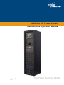
AMPS80 HP Power System
Installation & Operation Manual
member of The
Group™
Your Power Solutions Partner
This page has deliberately been left blank
'RF%5HY'
,QVWDOODWLRQ2SHUDWLRQ0DQXDO
127(
3KRWRJUDSKVFRQWDLQHGLQWKLVPDQXDODUHIRULOOXVWUDWLYHSXUSRVHVRQO\7KHVHSKRWRJUDSKV
PD\QRWPDWFK\RXULQVWDOODWLRQ
127(
2SHUDWRULVFDXWLRQHGWRUHYLHZWKHGUDZLQJVDQGLOOXVWUDWLRQVFRQWDLQHGLQWKLVPDQXDO
EHIRUHSURFHHGLQJ,IWKHUHDUHTXHVWLRQVUHJDUGLQJWKHVDIHRSHUDWLRQRIWKLVSRZHULQJV\V
WHPFRQWDFW$OSKD7HFKQRORJLHVRU\RXUQHDUHVW$OSKDUHSUHVHQWDWLYH
127(
$OSKDVKDOOQRWEHKHOGOLDEOHIRUDQ\GDPDJHRULQMXU\LQYROYLQJLWVHQFORVXUHVSRZHUVXS
SOLHVJHQHUDWRUVEDWWHULHVRURWKHUKDUGZDUHLIXVHGRURSHUDWHGLQDQ\PDQQHURUVXEMHFW
WRDQ\FRQGLWLRQQRWFRQVLVWHQWZLWKLWVLQWHQGHGSXUSRVHRULVLQVWDOOHGRURSHUDWHGLQDQ
XQDSSURYHGPDQQHURULPSURSHUO\PDLQWDLQHG
)RUWHFKQLFDOVXSSRUWFRQWDFW$OSKD7HFKQRORJLHV
&DQDGDDQG86$ ,QWHUQDWLRQDO (PDLO VXSSRUW#DOSKDFD
&RS\ULJKW
Copyright © 2010 Alpha Technologies Ltd. All rights reserved. Alpha is a registered trademark of Alpha Technologies.
No part of this documentation shall be reproduced, stored in a retrieval system, translated, transcribed, or
transmitted in any form or by any means manual, electric, electronic, electromechanical, chemical, optical, or
otherwise without prior explicit written permission from Alpha Technologies.
This documentation, the software it describes, and the information and know-how they contain constitute the
proprietary, confidential and valuable trade secret information of Alpha Technologies, and may not be used
for any unauthorized purpose, or disclosed to others without the prior written permission of Alpha Technologies.
The material contained in this document is for information only and is subject to change without notice.
While reasonable efforts have been made in the preparation of this document to assure its accuracy, Alpha
Technologies assumes no liability resulting from errors or omissions in this document, or from the use of the
information contained herein. Alpha Technologies reserves the right to make changes in the product design
without reservation and without notification to its users.
'RF%5HY'
7DEOHRI&RQWHQWV
6DIHW\ 6DIHW\6\PEROV
*HQHUDO6DIHW\
([WHUQDO%DWWHU\6DIHW\
8WLOLW\3RZHU&RQQHFWLRQ
(TXLSPHQW*URXQGLQJ
3URGXFW'HVFULSWLRQ 7KHRU\RI2SHUDWLRQ
6\VWHP&RPSRQHQWV
6\VWHP,QVWDOODWLRQ
,QVWDOODWLRQ1RWHV
5HFRPPHQGHG,QVWDOODWLRQ/D\RXW
8QSDFNLQJ,QVWUXFWLRQV
7UDQVSRUWLQJWKH&DELQHW
$QFKRULQJWKH&DELQHW
5HFRPPHQGHG$&DQG'&%UHDNHUVDQG:LUH6L]HV
&RQYHUWLQJIURP6LQJOHWR'XDO$&)HHG2SWLRQDO
,QSXW2XWSXW&DEOLQJ
'&%DWWHU\&DEOLQJ
$036+3,QYHUWHURU+\EULG6\VWHPZLWK0%66LQJOHDQG'XDO$&,QSXW)HHG
6WDUWLQJ6\VWHP)RUWKH)LUVW7LPH
,QYHUWHU5HPRWH2Q2II2SWLRQDO
6\VWHP2SHUDWLRQ ,QYHUWHU0RGXOH,QGLFDWRUV
76,QYHUWHU&RQWURO&DUG
8VLQJWKH&;&8QL¿HG6\VWHP&RQWUROOHU
6RIWZDUH2YHUYLHZ
&RQQHFWLRQV
4XLFN6WDUW
'RF%5HY'
&RQWUROOHU2SHUDWLRQ
5HFWL¿HU)HDWXUHV
7RROV5HTXLUHG 0DLQWHQDQFH 3UHYHQWLYH0DLQWHQDQFH
)DQ5HSODFHPHQW
5HPRYLQJ76,QYHUWHU&RQWURO&DUG
6XUJH6XSSUHVVLRQ5HSODFHPHQW
)XVH5HSODFHPHQW
6\QFKURQL]DWLRQ$IWHU0DLQWHQDQFHRU5HSDLU
7URXEOHVKRRWLQJ 1RQ5HFRYHUDEOH(UURU
5HFRYHUDEOH(UURU
1R(WKHUQHW&RPPXQLFDWLRQ
6\VWHP6DWXUDWHG
$&6HFRQGDU\6RXUFH/RVW
$&2XW1RW6\QFKURQL]HG
$&0DLQV/RVW
0DQXDO2II
2YHUORDG&XUUHQW
2YHUORDG7RR/RQJ
3KDVH1RW5HDG\
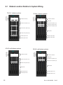
6\VWHP6SHFL¿FDWLRQV 0RGXOH/RFDWLRQ5HODWLYHWR6\VWHP:LULQJ
6SHFL¿FDWLRQVIRU,QYHUWHU0RGXOH
6SHFL¿FDWLRQVIRUN:5HFWL¿HU
6SDUH3DUWV &HUWL¿FDWLRQ :DUUDQW\ 'RF%5HY'
/LVWRI)LJXUHV
)LJ0LQLPXPUHTXLUHGFOHDUDQFHVDURXQGFDELQHW
)LJ$UUDQJHPHQWRIOLIWLQJH\HVRQWRSRIFDELQHW
)LJ0RXQWLQJKROHSDWWHUQGLPHQVLRQVLQLQFKHV
)LJ)URQWYLHZ'&FRQQHFWLRQV
)LJ/D\RXW7ZR'&MRLQLQJSODWHV
)LJ/D\RXWIRXU'&MRLQLQJSODWHV
)LJ&DEOLQJDQGKDUGZDUHDUUDQJHPHQW
)LJ5HSUHVHQWDWLYHV\VWHPZLULQJIRU$036LQYHUWHURUK\EULGV\VWHPZLWK0%6ZLWK
VLQJOH$&LQSXWIHHG
)LJ5HSUHVHQWDWLYHV\VWHPZLULQJIRU$036LQYHUWHUV\VWHPZLWKLQGHSHQGHQW$&LQSXW
IHHGIRU0%6
)LJ8QORFNLQJDQGORFNLQJDQLQYHUWHUPRGXOHIRUUHPRYDORULQVHUWLRQ
)LJ,QVHUWLQJDQGUHPRYLQJDQLQYHUWHUPRGXOH
)LJ,QVHUWLQJEODQNVLQRSHQVORWV
)LJ,QYHUWHUPRGXOHVWDWXVSRZHU/('V
)LJ2XWSXWSRZHULQGLFDWRU/('V
)LJ76IURQWSDQHO
)LJ&;&V\VWHPFRQWUROOHU
)LJ1DYLJDWLRQVFUHHQ
)LJ,OOXVWUDWLRQRIZHELQWHUIDFHZLQGRZVDPSOHKRPHSDJH
)LJ9LHZOLYHVWDWXVSDJH
)LJ9LHZOLYHVWDWXV²LQYHUWHUVSDJH
)LJ9LHZJURXSVWDWXVZLQGRZ²LQYHUWHUVSDJH
)LJ*URXSPDSSLQJZLQGRZ
)LJ6HWLQSXWZLQGRZ
)LJ6HWRXWSXWZLQGRZ
)LJ*HQHUDOVHWWLQJVZLQGRZ
)LJ0DQDJHFRQ¿J¿OHZLQGRZ
)LJ&RQ¿JXUHDODUPVZLQGRZ
)LJ6LJQDOVLQYHUWHUVZLQGRZ
)LJ&RUGH[&;5)9UHFWL¿HU
'RF%5HY'
1.
Safety
SAVE THESE INSTRUCTIONS:
This manual contains important safety instructions
that must be followed during the installation, servicing, and maintenance of the product. Keep it in a safe
place. Review the drawings and illustrations contained in this manual before proceeding. If there are any
questions regarding the safe installation or operation of this product, contact Alpha Technologies or the nearest Alpha representative. Save this document for future reference.
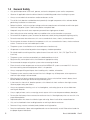
1.1
Safety Symbols
To reduce the risk of injury or death, and to ensure the continued safe operation of this product, the following
symbols have been placed throughout this manual. Where these symbols appear, use extra care and attention.
$77(17,21
7KHXVHRI$77(17,21LQGLFDWHVVSHFL¿FUHJXODWRU\FRGHUHTXLUHPHQWVWKDWPD\DIIHFWWKH
SODFHPHQWRIHTXLSPHQWDQGRULQVWDOODWLRQSURFHGXUHV
127(
$127(SURYLGHVDGGLWLRQDOLQIRUPDWLRQWRKHOSFRPSOHWHDVSHFL¿FWDVNRUSURFHGXUH
1RWHVDUHGHVLJQDWHGZLWKDFKHFNPDUNWKHZRUG127(DQGDUXOHEHQHDWKZKLFKWKH
LQIRUPDWLRQDSSHDUV
&$87,21
&$87,21LQGLFDWHVVDIHW\LQIRUPDWLRQLQWHQGHGWR35(9(17'$0$*(WRPDWHULDORU
HTXLSPHQW&DXWLRQVDUHGHVLJQDWHGZLWKD\HOORZZDUQLQJWULDQJOHWKHZRUG&$87,21
DQGDUXOHEHQHDWKZKLFKWKHLQIRUPDWLRQDSSHDUV
:$51,1*
:$51,1*SUHVHQWVVDIHW\LQIRUPDWLRQWR35(9(17,1-85<25'($7+WRSHUVRQQHO
:DUQLQJVDUHLQGLFDWHGE\DVKRFNKD]DUGLFRQWKHZRUG:$51,1*DQGDUXOHEHQHDWK
ZKLFKWKHLQIRUPDWLRQDSSHDUV
+27
7KHXVHRI+27SUHVHQWVVDIHW\LQIRUPDWLRQWR35(9(17%8516WRWKHWHFKQLFLDQRUXVHU
'RF%5HY'
1.2
General Safety
•
Only qualified personnel shall install, operate, and service the power system and its components.
•
Observe all applicable national and local electrical and building codes when installing the system.
•
Always assume electrical connections and/or conductors are live.
•
Turn off all circuit breakers and double-check potentially charged components with a voltmeter before
performing installation or maintenance.
•
Before installation, verify that the input voltage and current requirements of the load are within the specifications of the power system. Refer to the product nameplate label.
•
Keep tools away from walk areas to prevent personnel from tripping over the tools.
•
Wear safety glasses when working under any conditions that may be hazardous to your eyes.
•
Do not work on the power system, or connect or disconnect cables, during atmospheric lightning activity.
•
Do not let water enter the enclosure as this can cause electrical shorts, shocks, or electrocutions.
•
Do not remove the covers of electrical components as this can cause electrical shorts, shocks or electrocutions. There are no user serviceable parts inside.
•
The power system is certified for use in restricted access locations only.
•
All operators must be trained to perform the emergency shutdown procedure.
•
For hybrid models containing rectifiers, replace internal fuses with 200 A, 170 V, DC Type TPL or TGL
fuses only.
•
The power system must be connected only to a dedicated branch circuit.
•
Equip the utility service panel with a circuit breaker of appropriate rating.
•
Do not exceed the output rating of the system when connecting the load.
•
External metal surface temperatures on the rear of the AMPS80 HP system can exceed 70°C. Use caution when working around the equipment while it is in operation.
•
Always use proper lifting techniques when handling units, modules, or batteries.
•
The power system contains more than one live circuit. Voltage may still be present at the output even
when the input voltage is disconnected.
•
Minimize the risk of sparks and wear on the connectors. Always switch off the inverter’s battery circuit
breaker before connecting or disconnecting the battery pack.
•
In the event of a short-circuit, batteries present a risk of electrical shock and burns from high currents.
Observe proper safety precautions.
•
Always wear protective clothing, such as insulated gloves, and safety glasses or a face shield when
working with batteries.
•
Carry a supply of water, such as a water jug, to wash eyes or skin in case of exposure to battery electrolyte.
•
Do not allow live battery wires to contact the enclosure chassis. Shorting battery wires can result in a fire
or possible explosion.
•
Replace batteries with those of an identical type and rating. Never install old or untested batteries.
•
Only use insulated tools when handling batteries or working inside the enclosure.
•
Remove all rings, watches and other jewelry before servicing batteries.
•
Recycle used batteries. Spent or damaged batteries are environmentally unsafe. Refer to local codes for
the proper disposal of batteries.
'RF%5HY'
1.3 External Battery Safety
•
The power system requires an over-current protection device for the external batteries. The maximum
allowable current is typically 2500 A but can be less depending on the model. Follow the local electrical
codes.
•
Ensure that the external battery connection is equipped with a disconnect.
•
If the batteries are stored for extended periods before the installation, charge the batteries at least once
every three months to ensure optimum performance and maximum battery service life.
•
Refer to the battery manufacturer’s recommendation to select the correct “float” and “equalize” charge
voltage settings. Failure to do so can damage the batteries. Verify that the battery charger’s “float” and
“equalize” settings are correct.
•
The batteries are temperature sensitive. During extremely cold conditions, a battery’s charge acceptance is reduced and requires a higher charge voltage. During extremely hot conditions, a battery’s
charge acceptance is increased and requires a lower charge voltage. To allow for changes in temperature, the battery charger must be equipped with a temperature compensating system. For hybrid systems, refer to the rectifier manual for information about temperature compensation.
•
If the batteries appear to be overcharged or undercharged, first check for defective batteries and then
verify that the charger voltage settings are correct.
•
To ensure optimal performance, inspect the batteries according to the battery manufacturers recommendations. Check for signs of cracking, leaking, or unusual swelling. Some swelling is normal.
•
Check the battery terminals and connecting wires. Periodically clean the battery terminal connectors
and retighten them to the battery manufacturer's torque specifications. Spray the terminals with an approved battery terminal coating such as NCP-2 or No-Ox.
•
Verify that the polarity of the cables are correct before connecting the batteries to the power module. The
polarity is clearly marked on the batteries. The battery breaker will trip and the rectifiers may be damaged if the cables are connected with the wrong polarity.
1.4 Utility Power Connection
Connecting to the utility must be performed by qualified service personnel only and must comply with local
electrical codes. The utility power connection must be approved by the local utility before the installation.
'RF%5HY'
1.5
Equipment Grounding
To provide a ready, reliable source of backup power, the power system must be connected to an effective
grounding and Earthing system. The grounding system must be designed to protect both personnel and
equipment.
:$51,1*
/RZLPSHGDQFHJURXQGLQJLVPDQGDWRU\IRUSHUVRQQHOVDIHW\FULWLFDOIRUWKHSURSHURSHUD
WLRQRIWKHV\VWHPDQGPXVWEHLQSODFHDQGFRQQHFWHGWRWKHV\VWHPEHIRUHWKHVXSSO\
FDEOHVDUHFRQQHFWHG
1.5.1 Safety Ground
The safety ground is a two-part system, comprised of the utility service ground and the power system
ground.
Utility Service Ground
As a minimum requirement for the protection of equipment, the local utility service must provide a low-impedance path for fault current return to Earth. This must meet or exceed the requirements of the US National
Electrical Code or the Canadian Electrical Code.
Power System Ground
The power system ground consists of a low-impedance connection between the enclosure and an Earth
Ground, which must be located at least 6’ away from the utility earth connection. This impedance between
the system and Earth must not exceed 0.01 Ohms.
1.5.2 Lightning Strike Ground
Lightning strikes, grid switching, or other power surges on the power line and/or communications cable can
cause high-energy transients that can damage the power or communications systems. Without a low-impedance path to the ground, the current will travel through wires of varying impedance, which can produces
damaging high voltages. The best method to protect the system from damage is to divert these unwanted
high-energy transients along a low-impedance path to the ground.
A single-point grounding system provides a low-impedance path to ground. Proper bonding of the ground
rods is critical as this will ensure that the components of the grounding system appear as a single point of
uniform impedance. Use a surge arresting device that is electrically bonded to the power system ground.
'RF%5HY'
2.
Product Description
The Alpha Modular Power System 80HP (AMPS80 HP) is a unique, high performance AC and hybrid AC/DC
power system that is ideally suited to provide highly reliable back-up power to Cable Headend, Telecom or
Server room facilities.
The AMPS80 HP features hot swappable 2.5 kVA/2.0 kW inverter modules and optional 1.8 kW rectifier modules that are the building blocks of a highly reliable power system with 99.999% availability, 94% efficiency,
and high power density. A smart, unified controller with an integrated Ethernet/SNMP monitors and manages
both inverter and rectifier modules through a web based GUI and a local LCD touch screen. The AMPS80
HP is designed to be installed in a climate-controlled environment where ambient temperatures are between
-20°C to 40°C.
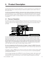
2.1 Theory of Operation
Each Alpha inverter module is equipped with both a DC input and an AC input, and also contains an AC-DC
and a DC-DC power conversion stage, which feed into an internal DC bus. The DC-AC inverter stage in each
module then takes this DC bus voltage and converts it into a 120 Vac output for the critical loads, see diagram below:
$036+30RGXOH%ORFN'LDJUDP
%RRVW
/
9GF
1
/
1
&$1EXVH[WHUQDO
FRPPXQLFDWLRQ
'63
'XDOUHGXQGDQWFRPPXQLFDWLRQDQG
V\QFKURQL]DWLRQEHWZHHQPRGXOHV
The commercial AC input is not directly connected to the AC output and there are two high frequency
conversion stages between the commercial AC and the customer’s critical loads at all times. The AC
output remains regulated when the AC input is between 80 V and 140 V. When the AC input voltage
drops below approximately 100 V, the DC-DC input stage starts augmenting AC line power with power
from the batteries. Below 80 Vac input, the AC input stage shuts down and all power is drawn from the
batteries. There is no "switching" between AC input and DC input. The control system in each module
simply decides what fraction of the power to the internal DC bus is acquired from the AC input versus
the DC input. Both converter stages are ready to supply full power anytime.
The user can choose either AC or DC input priority. If AC priority is chosen, the AMPS80 HP acts more
like an on-line, double conversion UPS. If AC commercial power is available, this power is filtered twice
and passed to the AC output. If the AC commercial power fails, the DC converter simply takes over and
supplies the power from the batteries.
If DC priority is chosen, AMPS80 HP acts more like an Inverter with AC bypass function. Normally, power
is drawn from the batteries. If DC power fails, the AC-DC converter takes over, still providing regulated
and filtered power to the load.
One of the largest advantages of the AMPS80 HP is that the "AC bypass" function is built into each module (no single point of failure) and the user can take advantage of the high efficiency AC mode of 94%
compared to 82% for typical rectifier/inverter systems without compromising regulation and filtering.
'RF%5HY'
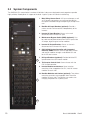
2.2
System Components
The AMPS80 HP is comprised of a number of individual subsystems designed to work together to provide
highly reliable, filtered power in support of the load. A typical system will contain the following:
1.
1
Main Wiring Access Panel: AC input and output as well
as DC battery connections are accessed through the
front panel and feed through the opening at the top of the
rack.
2. Rectifier AC Input Breakers (optional): Provide a
means to switch off the rectifiers independently of the
inverters.
3. Inverter AC Input Breaker: Serves as the main
disconnect for the inverter AC input.
2
4. Maintenance Bypass Switch (MBS) (optional): Can
be used to route power directly from the AC input to the
AC output, bypassing the inverter modules.
3
4
5. Inverter AC Output Breaker: Serves as the main
disconnect for the inverter AC outputs.
5
6. CXC Unified System Controller with integrated
Ethernet/ SNMP: Monitors and manages both inverter
and rectifier modules through a web-based GUI and
local LCD touch screen.
6
7.
7
DC Input Breakers (optional): Provide individual DC
input breakers for each inverter module.
8. T2S Inverter Control Card: Communicates with the
CXC Unified controller.
8
9. Inverter Modules and shelves: Up to 9 shelves
containing 4 hot-swappable 2500 VA / 2000 W inverter
modules on each shelf.
9
10. Rectifier Modules and shelves (optional): Two shelves
containing up to four hot-swappable 1800 W rectifier
modules on each shelf. The rectifiers are used as the
charging component of a hybrid system.
10
'RF%5HY'
3.
3.1
System Installation
Installation Notes
•
The AMPS80 HP is designed to be installed in a controlled environment, sheltered from rain, excessive
dust and other contaminants.
•
The system arrives pre-wired, and the installer is responsible for connecting the utility input to the
system, the battery strings, the system to the load, and the chassis and battery return to the reference
ground.
•
All wiring must be in accordance with applicable electrical codes.
•
Access to connection points is provided from the front of the system rack.
•
AC wires enter the cabinet through the top. DC wires enter the cabinet either through the top or the bottom of the cabinet.
•
The required gauge of the AC input, DC+/DC- input and AC output cabling is determined by the current
rating, Circuit Breaker rating, typical ambient temperatures and must meet the applicable local electrical codes. Typically the AC input and standard AC output is 6 wires (L1, L2, and L3, N, N, G) up to 350
kcmil THHW or RW90 type cable that will connect to the AMPS80 HP system with trade size up to 3.5
conduit.
•
A low voltage disconnect should be provided with the battery system.
:$51,1*
7RSUHYHQWHOHFWULFDOKD]DUGVVXFKDVVKRUWFLUFXLWVHQVXUHWKDWWKHV\VWHPLVIUHHRIGHEULV
VXFKDVPHWDO¿OLQJVVFUHZVHWFDIWHUWKHLQVWDOODWLRQLVFRPSOHWH
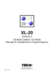
3.2 Recommended Installation Layout
Minimum required clearances
around the cabinet:
•
Rear: 12” (30 cm)
•
Sides: no clearance
required except 75 kVA
systems and systems
with TVSS option, which
require 36" (90 cm)
•
Top: 12” (30 cm)
•
Front: 33” (100 cm)
)LJ0LQLPXPUHTXLUHGFOHDUDQFHVDURXQGFDELQHW
'RF%5HY'
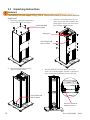
3.3
Unpacking Instructions
:$51,1*
7KH$036+3UDFNZHLJKVNJOE&DUHPXVWEHWDNHQWRHQVXUHWKDWLWGRHVQRW
WRSSOHRYHU
1.
Remove 6 screws from top panel to
access AMPS80 HP lifting eyes.
8VH3KLOOLSVKHDG
WRROWRUHPRYH
2. Remove 4 screws from each top 2 x 4
and 6 screws from each wooden side
piece to gain access to removal of the
front and rear wooden frames.
/LIWLQJH\HV
8VH3KLOOLSVKHDG
WRROWRUHPRYH
3. Remove 3 screws from the front
and rear wooden frames.
4. Remove AMPS80 HP metal side panels to gain
access to 4 interior lag bolts. Remove 4 lag bolts to
allow removal of the AMPS80 HP from the pallet.
8VH3KLOOLSVKHDG
WRROWRUHPRYH
A
8VHZUHQFKRU
VRFNHWWRUHPRYH
'RF%5HY'
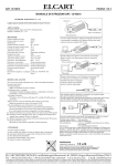
3.4 Transporting the Cabinet
The cabinet is shipped upright on a 122 cm x 122 cm (48" x 48") pallet and may be transported to the installation site either by forklift or overhead crane. The empty cabinet weighs approximately 270 kg (595 lb).
The height of the rack, including pallet and shipping material is 92" (234 cm). When tilting the rack to fit
through doors, tilt the rack toward the back and ensure that it is not subjected to sudden shock.
Use the supplied lifting eyes to lift the cabinet from the top. The lifting eyes are accessible by removing the
top sheet of wood from the shipping crate.
)LJ$UUDQJHPHQWRIOLIWLQJH\HVRQWRSRIFDELQHW
3.5 Anchoring the Cabinet
The cabinet must be fixed in place by means of anchor bolts. In areas prone to seismic events, use anchors
rated for the appropriate Seismic zone.
)LJ0RXQWLQJKROHSDWWHUQGLPHQVLRQVLQLQFKHV
'RF%5HY'
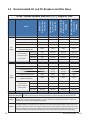
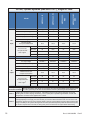
3.6 Recommended AC and DC Breakers and Wire Sizes
$&
LQSXW
RXWSXW
:LWK0%6
:LWKUHFWL¿HUV
$036+0%6
:LWK0%6
:LWKRXWUHFWL¿HUV
$0360%6
:LWKRXW0%6
:LWKUHFWL¿HUV
$036+
$&LQSXWYROWDJH
9
9
9
9
)XOOORDG$&LQSXWFXUUHQWSHUSKDVH
$
$
$
$
$&LQSXWSROHVZLULQJ
Z*
Z*
Z*
Z*
:LULQJ
Ɏ:\H
Ɏ:\H
Ɏ:\H
Ɏ:\H
5HFRPPHQGHG
$&LQSXWEUHDNHUIXVH
$
$
$
$
1(&&
NFPLO
NFPLO
NFPLO
&(&&
NFPLO
NFPLO
6HHGXDOIHHG
1(&&
NFPLO
NFPLO
6HHGXDOIHHG
&(&&
NFPLO
NFPLO
NFPLO
6HHGXDOIHHG
7RWDOPD[LPXP$&RXWSXW
N9$N:
N9$N:
N9$N:
N9$N:
$&RXWSXWYROWDJH
9
9
9
9
$&RXWSXWSROHVZLULQJ
Z*
Z*
Z*
Z*
:LULQJ
Ɏ:\H
Ɏ:\H
Ɏ:\H
Ɏ:\H
$&RXWSXWFXUUHQWSHUSKDVH
$
$
$
$
,QVWDOOHGLQYHUWHULQSXW
RXWSXWFLUFXLWEUHDNHU
$
$
$
$
1(&&
&(&&
NFPLO
NFPLO
NFPLO
NFPLO
1(&&
NFPLO
NFPLO
NFPLO
NFPLO
&(&&
NFPLO
NFPLO
NFPLO
NFPLO
5HFRPPHQGHG
$&LQSXWZLUHVL]H
&FRSSHU
$&
:LWKRXW0%6
0RGHO
:LWKRXWUHFWL¿HUV
$036
N9$SKDVHV\VWHPV$036VLQJOH$&IHHG
5HFRPPHQGHG
$&RXWSXWZLUHVL]H
&FRSSHU
$&LQSXWRXWSXW %R[OXJVDUHUDWHGIRUERWK$OXPLQXPDQG&RSSHUZLUHNFPLOWR$:*)DVWHQFODPSLQJVFUHZ
FRQQHFWLRQWHUPLQDOV WR1PLQOEVIRU$:*WRNFPLOZLUHRU1PLQOEVIRUWR$:*ZLUH
1RWH
,QYHUWHU$&,QSXW$&2XWSXWFRQQHFWLRQV&DOFXODWLRQVEDVHGRQIXOOORDGDQGFKDUJLQJFXUUHQW
GHUDWLQJZLWKFXUUHQWFDUU\LQJFRQGXFWRUV///;1GXHWRSRVVLEOHKLJKKDUPRQLFFRQWHQWORDG
7HPSHUDWXUHFRUUHFWLRQIDFWRUDSSOLHGZKHQQHHGHG
1RWH
0D[LPXP$&XWLOLW\VHUYLFHSURWHFWLRQIHHGLQJWKH$036+3LV$7KHDFWXDOVXSSO\FLUFXLWEUHDNHUPXVWEH
VL]HGDSSURSULDWHO\IRUWKHVXSSO\ZLUHXVHG&RQVXOW\RXUORFDODQGQDWLRQDOHOHFWULFDOFRGHV7KH$&VRXUFHPXVW
EHOLPLWHGWRN$VKRUWFLUFXLWFXUUHQW'RXEOHQHXWUDOLVVWURQJO\UHFRPPHQGHGIRU$&RXWSXWZLULQJDQG$&LQSXW
ZLULQJWRWKH0%6IRUɎV\VWHPVZLWKVLJQL¿FDQWQRQOLQHDULHUHFWL¿HGFDSDFLWLYHORDGV%HFDXVHWKH$&LQSXWWR
WKHLQYHUWHUVLVSRZHUIDFWRUFRUUHFWHG$&ZLULQJVROHO\WRWKHLQYHUWHUVGRHVQRWUHTXLUHGRXEOHQHXWUDOZLULQJ
'RF%5HY'
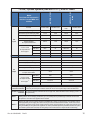
0RGHO
'XDOIHHGZLWKVHSDUDWH$&
IHHGIRULQYHUWHUV0%6DQG
UHFWL¿HUV
0%6
$036+
$036+
N9$SKDVHV\VWHPV$036GXDO$&IHHGV
$&IHHG
,QYHUWHUIHHG
5HFWL¿HUIHHG
,QYHUWHU0%6
IHHG
5HFWL¿HUIHHG
$&LQSXWYROWDJH
9
9
9
9
)XOOORDG$&LQSXWFXUUHQWSHUSKDVH
$
$
$
$
$&LQSXWSROHVZLULQJ
Z*
Z*
Z*
Z*
$&
:LULQJ
Ɏ:\H
Ɏ:\H
Ɏ:\H
Ɏ:\H
LQSXW
5HFRPPHQGHG
$&LQSXWEUHDNHUIXVH
$
$
$
$
1(&&
NFPLO
&(&&
NFPLO
1(&&
NFPLO
&(&&
NFPLO
NFPLO
5HFRPPHQGHG
$&LQSXWZLUHVL]H
&FRSSHU
$&
RXWSXW
7RWDOPD[LPXP$&RXWSXW
N9$N:
N9$N:
$&RXWSXWYROWDJH
9
9
$&RXWSXWSROHVZLULQJ
Z*
Z*
:LULQJ
Ɏ:\H
Ɏ:\H
$&RXWSXWFXUUHQWSHUSKDVH
$
$
,QVWDOOHGLQYHUWHULQSXW
RXWSXWFLUFXLWEUHDNHU
$
$
1(&&
&(&&
NFPLO
NFPLO
1(&&
NFPLO
NFPLO
&(&&
NFPLO
NFPLO
5HFRPPHQGHG
$&RXWSXWZLUHVL]H
&FRSSHU
$&LQSXWRXWSXW %R[OXJVDUHUDWHGIRUERWK$OXPLQXPDQG&RSSHUZLUHNFPLOWR$:*)DVWHQFODPSLQJVFUHZ
FRQQHFWLRQWHUPLQDOV WR1PLQOEVIRU$:*WRNFPLOZLUHRU1PLQOEVIRUWR$:*ZLUH
5HFWL¿HUFRQQHFWLRQ %R[OXJVDUHUDWHGIRUERWK$OXPLQXPDQG&RSSHUZLUHWR$:*)DVWHQFODPSLQJVFUHZWR
WHUPLQDOV 1PLQOEV
1RWH
,QYHUWHU$&,QSXW$&2XWSXWFRQQHFWLRQV&DOFXODWLRQVEDVHGRQIXOOORDGDQGFKDUJLQJFXUUHQW
GHUDWLQJZLWKFXUUHQWFDUU\LQJFRQGXFWRUV///;1GXHWRSRVVLEOHKLJKKDUPRQLFFRQWHQWORDG
7HPSHUDWXUHFRUUHFWLRQIDFWRUDSSOLHGZKHQQHHGHG
1RWH
0D[LPXP$&XWLOLW\VHUYLFHSURWHFWLRQIHHGLQJWKH$036+3LV$7KHDFWXDOVXSSO\FLUFXLWEUHDNHUPXVWEH
VL]HGDSSURSULDWHO\IRUWKHVXSSO\ZLUHXVHG&RQVXOW\RXUORFDODQGQDWLRQDOHOHFWULFDOFRGHV7KH$&VRXUFHPXVW
EHOLPLWHGWRN$VKRUWFLUFXLWFXUUHQW'RXEOHQHXWUDOLVVWURQJO\UHFRPPHQGHGIRU$&RXWSXWZLULQJDQG$&LQSXW
ZLULQJWRWKH0%6IRUɎV\VWHPVZLWKVLJQL¿FDQWQRQOLQHDULHUHFWL¿HGFDSDFLWLYHORDGV%HFDXVHWKH$&LQSXWWR
WKHLQYHUWHUVLVSRZHUIDFWRUFRUUHFWHG$&ZLULQJVROHO\WRWKHLQYHUWHUVGRHVQRWUHTXLUHGRXEOHQHXWUDOZLULQJ
'RF%5HY'
6LQJOH
6LQJOH
6LQJOH
$&LQSXWYROWDJH
9
RU9
9
RU9
9
RU9
9
RU9
)XOOORDG$&LQSXWFXUUHQWSHUSKDVH
$
$
$
$
$&LQSXWSROHVZLULQJ
Z*
Z*
Z*
Z*
$&
:LULQJ
SROH
SROH
SROH
SROH
LQSXW
5HFRPPHQGHG
$&LQSXWEUHDNHUIXVH
$
$
$
$
1(&&
NFPLO
NFPLO
&(&&
NFPLO
6HHGXDOIHHG
1(&&
NFPLO
6HHGXDOIHHG
&(&&
O
NFPLO
6HHGXDOIHHG
7RWDOPD[LPXP$&RXWSXW
N9$N:
N9$N:
N9$N:
N9$N:
$&RXWSXWYROWDJH
9
RU9
9
RU9
9
RU9
9
RU9
$&RXWSXWSROHVZLULQJ
Z*
Z*
Z*
Z*
:LULQJ
SROH
SROH
SROH
SROH
$&
$&RXWSXWFXUUHQWSHUSKDVH
$
$
$
$
RXWSXW
,QVWDOOHGLQYHUWHULQSXW
RXWSXWFLUFXLWEUHDNHU
$
$
$
$
1(&&
&(&&
NFPLO
NFPLO
NFPLO
NFPLO
1(&&
NFPLO
NFPLO
NFPLO
NFPLO
&(&&
NFPLO
NFPLO
NFPLO
NFPLO
5HFRPPHQGHG
$&LQSXWZLUHVL]H
&FRSSHU
5HFRPPHQGHG
$&RXWSXWZLUHVL]H
&FRSSHU
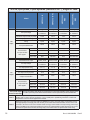
0%6
6LQJOH
0%6
$036+
)HHG
0RGHO
$036
$036
$036+
N9$VSOLWSKDVHSROHV\VWHPV$036VLQJOH$&IHHG
$&LQSXWRXWSXW %R[OXJVDUHUDWHGIRUERWK$OXPLQXPDQG&RSSHUZLUHNFPLOWR$:*)DVWHQFODPSLQJVFUHZ
FRQQHFWLRQWHUPLQDOV WR1PLQOEVIRU$:*WRNFPLOZLUHRU1PLQOEVIRUWR$:*ZLUH
1RWH
,QYHUWHU$&,QSXW$&2XWSXWFRQQHFWLRQV&DOFXODWLRQVEDVHGRQIXOOORDGDQGFKDUJLQJFXUUHQW
GHUDWLQJZLWKFXUUHQWFDUU\LQJFRQGXFWRUV///;1GXHWRSRVVLEOHKLJKKDUPRQLFFRQWHQWORDG
7HPSHUDWXUHFRUUHFWLRQIDFWRUDSSOLHGZKHQQHHGHG
1RWH
0D[LPXP$&XWLOLW\VHUYLFHSURWHFWLRQIHHGLQJWKH$036+3LV$7KHDFWXDOVXSSO\FLUFXLWEUHDNHUPXVWEH
VL]HGDSSURSULDWHO\IRUWKHVXSSO\ZLUHXVHG&RQVXOW\RXUORFDODQGQDWLRQDOHOHFWULFDOFRGHV7KH$&VRXUFHPXVW
EHOLPLWHGWRN$VKRUWFLUFXLWFXUUHQW'RXEOHQHXWUDOLVVWURQJO\UHFRPPHQGHGIRU$&RXWSXWZLULQJDQG$&LQSXW
ZLULQJWRWKH0%6IRUɎV\VWHPVZLWKVLJQL¿FDQWQRQOLQHDULHUHFWL¿HGFDSDFLWLYHORDGV%HFDXVHWKH$&LQSXWWR
WKHLQYHUWHUVLVSRZHUIDFWRUFRUUHFWHG$&ZLULQJVROHO\WRWKHLQYHUWHUVGRHVQRWUHTXLUHGRXEOHQHXWUDOZLULQJ
'RF%5HY'
'XDOIHHGZLWKVHSDUDWH$&
IHHGIRULQYHUWHUV0%6DQG
UHFWL¿HUV
$&IHHG
,QYHUWHUIHHG
5HFWL¿HUIHHG
,QYHUWHU0%6
IHHG
5HFWL¿HUIHHG
$&LQSXWYROWDJH
9
RU9
9
RU9
9
RU9
9
RU9
)XOOORDG$&LQSXWFXUUHQWSHUSKDVH
$
$
$
$
$&LQSXWSROHVZLULQJ
Z*
Z*
Z*
Z*
:LULQJ
SROH
SROH
SROH
SROH
5HFRPPHQGHG
$&LQSXWEUHDNHUIXVH
$
$
$
$
1(&&
&(&&
1(&&
&(&&
$&
5HFRPPHQGHG
$&LQSXWZLUHVL]H
&FRSSHU
$&
RXWSXW
0%6
$036+
0RGHO
LQSXW
$036+
N9$VSOLWSKDVHSROHV\VWHPV$036GXDO$&IHHGV
7RWDOPD[LPXP$&RXWSXW
N9$N:
N9$N:
$&RXWSXWYROWDJH
9RU9
9RU9
$&RXWSXWSROHVZLULQJ
Z*
Z*
:LULQJ
SROH
SROH
$&RXWSXWFXUUHQWSHUSKDVH
$
$
,QVWDOOHGLQYHUWHULQSXW
RXWSXWFLUFXLWEUHDNHU
$
$
1(&&
&(&&
NFPLO
NFPLO
1(&&
NFPLO
NFPLO
&(&&
NFPLO
NFPLO
5HFRPPHQGHG
$&RXWSXWZLUHVL]H
&FRSSHU
$&LQSXWRXWSXW %R[OXJVDUHUDWHGIRUERWK$OXPLQXPDQG&RSSHUZLUHNFPLOWR$:*)DVWHQFODPSLQJVFUHZ
FRQQHFWLRQWHUPLQDOV WRLQOEV1PIRU$:*WRNFPLOZLUHRULQOEV1PIRUWR$:*ZLUH
5HFWL¿HUFRQQHFWLRQ %R[OXJVDUHUDWHGIRUERWK$OXPLQXPDQG&RSSHUZLUHWR$:*)DVWHQFODPSLQJVFUHZWR
WHUPLQDOV 1PLQOEV
1RWH
,QYHUWHU$&,QSXW$&2XWSXWFRQQHFWLRQV&DOFXODWLRQVEDVHGRQIXOOORDGDQGFKDUJLQJFXUUHQW
GHUDWLQJZLWKFXUUHQWFDUU\LQJFRQGXFWRUV///;1GXHWRSRVVLEOHKLJKKDUPRQLFFRQWHQWORDG
7HPSHUDWXUHFRUUHFWLRQIDFWRUDSSOLHGZKHQQHHGHG
1RWH
0D[LPXP$&XWLOLW\VHUYLFHSURWHFWLRQIHHGLQJWKH$036+3LV$7KHDFWXDOVXSSO\FLUFXLWEUHDNHUPXVWEH
VL]HGDSSURSULDWHO\IRUWKHVXSSO\ZLUHXVHG&RQVXOW\RXUORFDODQGQDWLRQDOHOHFWULFDOFRGHV7KH$&VRXUFHPXVW
EHOLPLWHGWRN$VKRUWFLUFXLWFXUUHQW'RXEOHQHXWUDOLVVWURQJO\UHFRPPHQGHGIRU$&RXWSXWZLULQJDQG$&LQSXW
ZLULQJWRWKH0%6IRUɎV\VWHPVZLWKVLJQL¿FDQWQRQOLQHDULHUHFWL¿HGFDSDFLWLYHORDGV%HFDXVHWKH$&LQSXWWR
WKHLQYHUWHUVLVSRZHUIDFWRUFRUUHFWHG$&ZLULQJVROHO\WRWKHLQYHUWHUVGRHVQRWUHTXLUHGRXEOHQHXWUDOZLULQJ
'RF%5HY'
6LQJOH
6LQJOH
6LQJOH
$&LQSXWYROWDJH
9
9
9
9
)XOOORDG$&LQSXWFXUUHQWSHUSKDVH
$
$
$
$
$&LQSXWSROHVZLULQJ
Z*
Z*
Z*
Z*
:LULQJ
Ɏ:\H
Ɏ:\H
Ɏ:\H
Ɏ:\H
LQSXW
5HFRPPHQGHG
$&LQSXWEUHDNHUIXVH
$
$
$
$
1(&&
&(&&
1(&&
&(&&
7RWDOPD[LPXP$&RXWSXW
N9$N:
N9$N:
N9$N:
N9$N:
$&RXWSXWYROWDJH
9
9
9
9
$&RXWSXWSROHVZLULQJ
Z*
Z*
Z*
Z*
:LULQJ
Ɏ:\H
Ɏ:\H
Ɏ:\H
Ɏ:\H
$&RXWSXWFXUUHQWSHUSKDVH
$
$
$
$
,QVWDOOHGLQYHUWHULQSXW
RXWSXWFLUFXLWEUHDNHU
$
$
$
$
1(&&
&(&&
1(&&
&(&&
5HFRPPHQGHG
$&LQSXWZLUHVL]H
&FRSSHU
$&
RXWSXW
5HFRPPHQGHG
$&RXWSXWZLUHVL]H
&FRSSHU
0%6
$036+
6LQJOH
$036
$036
)HHG
0RGHO
$&
$036+
0%6
N9$SKDVHV\VWHPV$036VLQJOH$&IHHG
$&LQSXWRXWSXW %R[OXJVDUHUDWHGIRUERWK$OXPLQXPDQG&RSSHUZLUHNFPLOWR$:*)DVWHQFODPSLQJVFUHZ
FRQQHFWLRQWHUPLQDOV WR1PLQOEVIRU$:*WRNFPLOZLUHRU1PLQOEVIRUWR$:*ZLUH
1RWH
,QYHUWHU$&,QSXW$&2XWSXWFRQQHFWLRQV&DOFXODWLRQVEDVHGRQIXOOORDGDQGFKDUJLQJFXUUHQW
GHUDWLQJZLWKFXUUHQWFDUU\LQJFRQGXFWRUV///;1GXHWRSRVVLEOHKLJKKDUPRQLFFRQWHQWORDG
7HPSHUDWXUHFRUUHFWLRQIDFWRUDSSOLHGZKHQQHHGHG
1RWH
0D[LPXP$&XWLOLW\VHUYLFHSURWHFWLRQIHHGLQJWKH$036+3LV$7KHDFWXDOVXSSO\FLUFXLWEUHDNHUPXVWEH
VL]HGDSSURSULDWHO\IRUWKHVXSSO\ZLUHXVHG&RQVXOW\RXUORFDODQGQDWLRQDOHOHFWULFDOFRGHV7KH$&VRXUFHPXVW
EHOLPLWHGWRN$VKRUWFLUFXLWFXUUHQW'RXEOHQHXWUDOLVVWURQJO\UHFRPPHQGHGIRU$&RXWSXWZLULQJDQG$&LQSXW
ZLULQJWRWKH0%6IRUɎV\VWHPVZLWKVLJQL¿FDQWQRQOLQHDULHUHFWL¿HGFDSDFLWLYHORDGV%HFDXVHWKH$&LQSXWWR
WKHLQYHUWHUVLVSRZHUIDFWRUFRUUHFWHG$&ZLULQJVROHO\WRWKHLQYHUWHUVGRHVQRWUHTXLUHGRXEOHQHXWUDOZLULQJ
'RF%5HY'
6LQJOH
6LQJOH
6LQJOH
$&LQSXWYROWDJH
9
RU9
9
RU9
9
RU9
9
RU9
)XOOORDG$&LQSXWFXUUHQWSHUSKDVH
$
$
$
$
$&LQSXWSROHVZLULQJ
Z*
Z*
Z*
Z*
$&
:LULQJ
SROH
SROH
SROH
SROH
LQSXW
5HFRPPHQGHG
$&LQSXWEUHDNHUIXVH
$
$
$
$
1(&&
&(&&
1(&&
&(&&
7RWDOPD[LPXP$&RXWSXW
N9$N:
N9$N:
N9$N:
N9$N:
$&RXWSXWYROWDJH
9
RU9
9
RU9
9
RU9
9
RU9
$&RXWSXWSROHVZLULQJ
Z*
Z*
Z*
Z*
:LULQJ
SROH
SROH
SROH
SROH
$&
$&RXWSXWFXUUHQWSHUSKDVH
$
$
$
$
RXWSXW
,QVWDOOHGLQYHUWHULQSXW
RXWSXWFLUFXLWEUHDNHU
$
$
$
$
1(&&
&(&&
1(&&
&(&&
5HFRPPHQGHG
$&LQSXWZLUHVL]H
&FRSSHU
5HFRPPHQGHG
$&RXWSXWZLUHVL]H
&FRSSHU
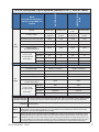
0%6
6LQJOH
0%6
$036+
)HHG
0RGHO
$036
$036
$036+
N9$VSOLWSKDVHSROHV\VWHPV$036VLQJOH$&IHHG
$&LQSXWRXWSXW %R[OXJVDUHUDWHGIRUERWK$OXPLQXPDQG&RSSHUZLUHNFPLOWR$:*)DVWHQFODPSLQJVFUHZ
FRQQHFWLRQWHUPLQDOV WR1PLQOEVIRU$:*WRNFPLOZLUHRU1PLQOEVIRUWR$:*ZLUH
1RWH
,QYHUWHU$&,QSXW$&2XWSXWFRQQHFWLRQV&DOFXODWLRQVEDVHGRQIXOOORDGDQGFKDUJLQJFXUUHQW
GHUDWLQJZLWKFXUUHQWFDUU\LQJFRQGXFWRUV///;1GXHWRSRVVLEOHKLJKKDUPRQLFFRQWHQWORDG
7HPSHUDWXUHFRUUHFWLRQIDFWRUDSSOLHGZKHQQHHGHG
1RWH
0D[LPXP$&XWLOLW\VHUYLFHSURWHFWLRQIHHGLQJWKH$036+3LV$7KHDFWXDOVXSSO\FLUFXLWEUHDNHUPXVWEH
VL]HGDSSURSULDWHO\IRUWKHVXSSO\ZLUHXVHG&RQVXOW\RXUORFDODQGQDWLRQDOHOHFWULFDOFRGHV7KH$&VRXUFHPXVW
EHOLPLWHGWRN$VKRUWFLUFXLWFXUUHQW'RXEOHQHXWUDOLVVWURQJO\UHFRPPHQGHGIRU$&RXWSXWZLULQJDQG$&LQSXW
ZLULQJWRWKH0%6IRUɎV\VWHPVZLWKVLJQL¿FDQWQRQOLQHDULHUHFWL¿HGFDSDFLWLYHORDGV%HFDXVHWKH$&LQSXWWR
WKHLQYHUWHUVLVSRZHUIDFWRUFRUUHFWHG$&ZLULQJVROHO\WRWKHLQYHUWHUVGRHVQRWUHTXLUHGRXEOHQHXWUDOZLULQJ
'RF%5HY'
$036
$036+
$036
$036+
$036
$036+
N:
N:
N:
N:
$
$
$
$
$
$
$
$
$036
$036+
'&EUHDNHUDQGZLUHVL]HV
0RGHO
0D[LPXP'&,QSXWZDWWDJH
0D[LPXP'&,QSXW&XUUHQW
#9GFIXOOORDG
'&LQSXWFXUUHQW#9
'&
ORDG
LQSXW
0D[LPXP'&LQSXWEUHDNHU
5HFRPPHQGHG
PLQLPXP'&
EUHDNHUUDWLQJ
UDWHGSHU
IHHG
$PD[LPXPN$6&&
6LQJOH'&
IHHG
$
$
$
$
'XDO'&
IHHG
$
$
$
$
4XDG'&
IHHG
$
$
$
$
1RWH
/RZHUEUHDNHUUDWLQJVFDQEHXVHGLIWKHV\VWHPLVVL]HGZLWKUHGXQGDQF\RUWKHV\VWHPZLOOQRWEHIXOO\
ORDGHG
1RWH
*URXQGERQGLQJZLUHPXVWEHVL]HGIRUWKH'&FXUUHQW
1RWH
'&LQSXWEUHDNHUUHFRPPHQGDWLRQEDVHGRQORDGFXUUHQWDW9GFIRUDIXOO\SRSXODWHGV\VWHP
1RWH
'&VRXUFHPXVWEHOLPLWHGWRN$6&&
'&ZLUHVL]HYHUVXVEUHDNHUVL]H
%UHDNHUVL]H
$
$
$
$
$
$
$
$
1(&
5HFRPPHQGHG
86$
'&:LUHVL]H
&FRSSHU
&(&
VLQJOHIHHG
&DQDGD
[
NFPLO
[
NFPLO
NFPLO
RU[ NFPLO
NFPLO
2222
22
[
NFPLO
[
NFPLO
NFPLO
RU[ NFPLO NFPLO
NFPLO
222
'RF%5HY'
3.7 Converting from Single to Dual AC Feed (Optional)
:$51,1*
7RSUHYHQWHOHFWULFDOKD]DUGVVZLWFKRIIDOO$&DQG'&VRXUFHV
3.7.1
Tools Required
•
Phillips screw driver
•
3/8” wrench or socket
•
3/16” hex key
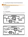
3.7.2 Wiring Diagrams
To convert the AMPS80 HP from single AC feed to dual AC feed, first remove the internal rectifier powering
wiring. Once this wiring is removed, install the inverter and the rectifier power wiring according to the diagrams below.
Single AC feed
Dual AC feed
'RF%5HY'
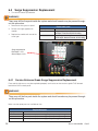
3.7.3
Remove Rectifier Wiring
:$51,1*
%HIRUHUHPRYLQJWKHZLULQJDFFHVVSDQHOPDNHVXUHDOOSRZHUWRWKHXQLWLVVZLWFKHGRII
5HPRYHWKHZLULQJ
DFFHVVSDQHOWR
JDLQDFFHVVWRWKH
ZLULQJFRPSDUWPHQW
5HFWL¿HUWHUPLQDOEORFN
'RF%5HY'
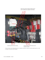
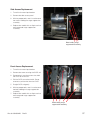
5HPRYHWKHLQWHUQDOUHFWL¿HUSRZHULQJZLUHV
EHIRUHLQVWDOOLQJWKHVHSDUDWHUHFWL¿HUIHHG
'LVFRQQHFWZLWKDKH[NH\
'LVFRQQHFWWKHQXWZLWKD
ZUHQFKRUVRFNHW
Once the internal rectifier powering wires have been removed, the external rectifier powering wires can be
installed in the rectifier terminal block.
'RF%5HY'
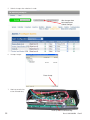
3.8
Input/Output Cabling
The illustrations below show the locations of the AC input, DC output, and AC output connection points:
1.
9
Rectifier AC input circuit breakers
DC1
2. Rectifier AC input terminals
DC3
DC4
3. Industrial grade surge suppression
modules.
7
4. AC input ground
6
5. AC input termination points for L1, L2, L3
6. AC neutral connection points
DC2
8
4
5
3
DC1
DC2
DC3
7.
Protective panel between AC & DC
connections
8. DC- bus, DC1, DC2, DC3, DC4
DC4
2
10
9. DC+ bus, DC1, DC2, DC3, DC4 input
connectors shown with one 4DC
shorting bar
11
12
13
10. AC output connection points; L1, L2, L3
11. Ground bus
12. AC output ground
1
14
13. Secondary AC output ground
AC input and AC output wires are connected
to box lugs rated for 350 kcmil to #6 AWG.
'RF%5HY'
The illustrations below show the dimensions and spacing for DC connections and the supplied joining plates.
)LJ)URQWYLHZ'&FRQQHFWLRQV
)LJ/D\RXW7ZR'&MRLQLQJSODWHV
)LJ/D\RXWIRXU'&MRLQLQJSODWHV
'RF%5HY'
3.9 DC Battery Cabling
DC battery cable terminations are designed for two-hole spade lugs crimped to the cabling, then attached to
the bus bars with 3" hardware. Depending upon the gauge of the input wiring used, the connections may be
made either singly or with two back-to-back lugs per mounting hole. Each bar (DC+, DC-) can accept seven
2-hole ½" mounting lugs on 1-3/4" centers or seven 2-hole 3/8" lugs on 1" centers.
Bus bar tie kits for DC+ and DC- are included to allow the installer the option to make a single battery connection or up to 4 separate battery connection (A/B feeds or A/B/C/D feeds).
,QSXWFDEOLQJ
RUKDUGZDUH
7LHEDU
%XVEDU
)LJ&DEOLQJDQGKDUGZDUHDUUDQJHPHQW
'RF%5HY'
3.10 AMPS80 HP Inverter or Hybrid System with MBS; Single
and Dual AC Input Feed
These diagrams show the logical internal connections. They are not a detailed representation of the actual
internal system wiring.
)LJ5HSUHVHQWDWLYHV\VWHPZLULQJIRU$036LQYHUWHURUK\EULGV\VWHPZLWK0%6ZLWKVLQJOH$&LQSXWIHHG
)LJ5HSUHVHQWDWLYHV\VWHPZLULQJIRU$036LQYHUWHUV\VWHPZLWKLQGHSHQGHQW$&LQSXWIHHGIRU0%6
'RF%5HY'
Reference Notes:
The AMPS80 HP system is preconfigured from the factory for a single AC feed per phase for inverters, a
maintenance bypass switch, and rectifiers if present.
•
If the AC input neutral is connected, remove the neutral to ground bonding wire. The neutral to ground
wire is provided for systems without AC Input connections in which case the inverter output is considered a separately derived source and the AC output neutral must be connected to earth ground.
•
In a 3-phase system equipped with an internal maintenance bypass switch and a load with a significant
distortion power factor, it is strongly recommended to provide the AC input and AC output connection
with a double neutral feed. Non-power factor corrected IT power supplies with rectified-capacitive loads
can contain high levels of 3rd harmonics that are created in such 3-phase systems. The current in the
neutral line can easily be twice the current in the line currents.
•
DC tie bars are supplied to allow dual A/B battery feed (DC1 shorted to DC2 and DC3 shorted to DC4)
or single battery feed (DC1 - 4 are shorted)
•
If the system is equipped with the optional rectifiers, each rectifier shelf in a hybrid system is only connected to one of the DC- battery feeds, the top shelf to DC1, and the bottom rectifier shelf is connected
to DC4. In a system with four independent battery feeds, two of these battery banks will not be charged
from the AMPS80 HP rectifiers. When using two independent A/B feeds, DC1 should be shorted to DC2
and DC3 shorted to DC4 at the AMPS80 HP DC connection points. Shorting bars are provided.
* Connections and components relating to L3 are only present for 120/208 V, 3-phase systems.
** Connections and components relating to L2 are only present for 120/240 V split phase and 120/208 V
3-phase systems.
'RF%5HY'
3.11
Starting System For the First Time
3.11.1
Tools Required
The following tools are required to commission the AMPS80 HP system for the first time:
•
Medium flat screwdriver with approximately 3/8” (5 mm) blade width.
•
True RMS digital multimeter.
•
Computer with Ethernet port and Internet Explorer 8 or later.
•
Crossover Ethernet cable if a computer is directly connected to the CXC controller.
•
Straight through Ethernet cable if the network connections are made through a router or hub.
•
Torque wrench.
•
3/8” hex driver.
&;&5(WKHUQHWSRUW
3.11.2
Start up Procedure
If your system does not have an AC input supply, i.e. there is no bypass function and the system always operates from DC input, ignore the instructions related to the AC input.
:$51,1*
7KH$036+3PXVWKDYHQRSRZHUDQGQRPRGXOHVLQVWDOOHG
1.
Verify that the AMPS80 HP system is mechanically secured to the floor or other structure.
2. Verify that the AMPS80 HP system is correctly and securely connected to the utility and batteries:
a. For the battery connections, follow the manufacturers recommendations and record the torques.
b. For the AC connections, torque #1 AWG - 350 kcmil wire to 375 in-lbs (42 N-m), and #6 - #2 AWG
wire to 200 in-lbs (23 N-m).
c. If rectifier wiring is installed, torque the connections to 120 in-lbs (14 N-m).
3. Verify that the AMPS80 HP system is correctly and securely grounded to the building grounding system.
4. Verify that all load distribution breakers are switched off.
5. Verify that the inverter AC input circuit breaker of the AMPS80 HP system is in the OFF position.
6. If the rectifier option is installed, verify that the rectifier AC input circuit breakers of the AMPS80 HP
system are in the OFF position.
7.
Verify that the inverter AC output circuit breaker of the AMPS80 HP system is in the OFF position.
'RF%5HY'
8. If equipped with a maintenance bypass switch (MBS), place this switch in the INVERTER mode.
9. Switch on the AC mains/utility power. Verify the AMPS80 HP system AC input and output voltages at the
AC wiring terminals:
a. The voltage from Neutral to L1 / L2 / L3 must be approximately 120 V.
b. The voltage from L1 to L2, L2 to L3, L3 to L1 must be approximately 208 V for a 3 phase system, or
the voltage from L1 to L2 must be approximately 240 V for a split phase system.
c. The voltage from Neutral to Earth Ground must be near zero volts.
$&LQSXWOXJV
/OHIW
/PLGGOH
/ULJKW
9
DC1
DC2
8
1HXWUDOOXJV
DC3
DC4
7
6
4
5
3
DC1
DC2
DC3
$&RXWSXWOXJV
/OHIW
OPLGGOH
/ULJKW
DC4
(DUWKJURXQGOXJV
2
10
2SWLRQDOUHFWL¿HU
$&LQSXWEUHDNHU
11
12
13
1
14
10. Ensure that all the batteries are disconnected, all rectifier modules are removed, all fuses are pulled, and
all circuit breakers are switched off. Triple check the polarity of the battery connections.
11. If the system includes the rectifier option, install one rectifier module. Switch on the AC power to the
rectifier and allow it to start up. Verify that the system starts up OK and that the controller switches on.
12. Check that the battery polarity is correct and then switch on the breakers, fuses, or circuit breakers for
the batteries. If there is no means to disconnect the batteries, reduce the rectifier output voltage using
the controller. To avoid sparks, match the rectifier voltage to the battery voltage to within 0.5 V.
a. The DC+ (positive) terminal voltage on the AMPS80 HP is near the earth ground. The battery positive
ground connection should be made near the battery.
b. The DC- (negative) terminal voltage is approximately 48 Vdc relative to the chassis ground.
c. The CXCR controller display initializes with three LEDs blinking for a few seconds. The LCD will show
the correct DC voltage.
13. If the system includes the rectifier option, install one rectifier module.
14. Switch on all the rectifier AC input breakers. Verify that the AC LED on the rectifier front panel illuminates
after a few seconds.
15. Connect a computer to the CXCR controller. See the Connections section in this manual or Section 9.1
“Establishing a network Connection via a Crossover Cable” in the Cordex Controller Software manual.
The 48 V DC power must be switched on before the CXCR controller can operate. Provide either DC
power on the main DC1 or DC4 connections, or switch on at least one rectifier if it is available.
'RF%5HY'
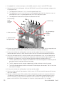
:$51,1*
'RQRWLQVWDOODOOLQYHUWHUPRGXOHVDWRQFHEXWORDGRQHLQYHUWHUPRGXOHLQWRDQRSHQVORWIRU
HDFK$&SKDVH7KLVDOORZWKHLQLWLDOVHWXSRIWKH$&SKDVHV$OOUHPDLQLQJPRGXOHVZLOO
DXWRPDWLFDOO\WDNHRQWKHFRQ¿JXUDWLRQVRIWKHVH³VHHG´PRGXOHV6HHGLDJUDPVXQGHU6HF
WLRQ0RGXOH/RFDWLRQ5HODWLYHWR6\VWHP:LULQJIRU$&SKDVHORFDWLRQV6HHEHORZIRU
GHWDLOHGPRGXOHLQVHUWLRQUHPRYDOLQVWUXFWLRQV<RXPD\QRWZDQWWRFORVHORFNWKHJULOODW
WKLVWLPHEHFDXVHWKHPRGXOHPD\KDYHWREHUHPRYHGDWDODWHUVWDJH
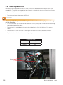
&$87,21
,PSURSHULQVWDOODWLRQRUUHPRYDORIPRGXOHVFDQEUHDNODWFKLQJFRPSRQHQWV
8QORFN
/RFN
,QVHUWDÀDWKHDGVFUHZGULYHULQWRWKHFHQWHUÀDS
QRWFKDQGSU\RSHQWKHFHQWHUÀDS7KHQSXOORXWWKH
PRGXOHE\SXOOLQJRQWKHFHQWHUÀDSZLWKERWKKDQGV
/HDYHWKHPRGXOHSODVWLFIURQWJULOOLQWKHRSHQXQ
ORFNHGSRVLWLRQWKHQVOLGHSXVKWKHPRGXOHDOOWKH
ZD\LQWRWKHPRGXOHVORWDQGWKHQFORVHWKHÀDS
)LJ8QORFNLQJDQGORFNLQJDQLQYHUWHUPRGXOHIRUUHPRYDORULQVHUWLRQ
3ODFHPRGXOHLQWRVKHOI
3UHVVPRGXOHLQWRSODFHDQG
HQVXUHFRQQHFWLRQLVHQJDJHG
&ORVHFRYHUDQGVQDSPRGXOH
LQWRSODFH,IFRYHUGRHVQRWFORVH
HDVLO\UHSHDW6WHS
)LJ,QVHUWLQJDQGUHPRYLQJDQLQYHUWHUPRGXOH
16. Switch on the inverter AC input breaker on the AMPS80 HP front panel. Verify that the AC input LEDs turn
on for each module. The LEDs may flash in different colors but this behavior should not be a cause for
concern.
17. Using the CXC web interface, verify that the modules are recognized and the voltages and currents of
the modules are displayed. Ignore any alarms at this point. The current readings at no load are not
very precise. Select: Inverters -> View Live Status
18. Select the first module listed in the Live View Status. The corresponding LEDs for that inverter will
flash for a few seconds. Using the pull down box in the Module number column, set the number to the
corresponding AC phase. Repeat this for the second module (for split and 3 phase systems) and the
third module (for 3 phase systems).
'RF%5HY'
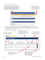
19. Select Inverters > View Live Status
$SXOOGRZQPHQXDOORZVWKHXVHUWRUHDVVLJQ
WKHLQYHUWHU
VPRGXOHQXPEHULQWKHUHSRUWIRU
H[DPSOHWRFRUUHVSRQGZLWKWKHLUSK\VLFDOORFD
WLRQRQWKHVKHOI6HOHFWLQJDPRGXOHQXPEHU
WKDWLVDOUHDG\XVHGZLOOVZDSWKHWZRPRGXOHV
6HOHFWDURZWRVHQGD
/RFDWHFRPPDQGWKHLQ
YHUWHUPRGXOH
V/('VZLOO
WKHQEOLQNPRPHQWDULO\
20. Select the first module listed in the Live View Status. The corresponding LEDs for that inverter will
flash for a few seconds. Using the pull down box in the Module number column, set the number to the
corresponding AC phase. Repeat this for the second module (for split and 3 phase systems) and the
third module (for 3 phase systems)
21. Select Inverters > Group Mapping
0DWFKWKH$&LQSXWJURXS
WRWKH$&RXWSXWJURXS
6ZLWFKRIIWKHLQYHUWHUEH
IRUHFKDQJLQJWKHLQYHUWHU¶V
$&RXWSXWJURXS
)RUDVSOLWSKDVH9V\VWHP
FOLFNRQKHDGLQJEXWWRQ
)RUDSKDVH9V\VWHP
FOLFNRQKHDGLQJEXWWRQ
7XUQRIIDOOLQYHUWHUVEH
IRUHFKDQJLQJWKHQXP
EHURI$&SKDVHJURXSV
&OLFNWKLVEXWWRQWRVZLWFKWKHLQYHUWHU
212))8VHZLWKFDXWLRQ
*UHHQ LQYHUWHULV21
%ODFN LQYHUWHULV2))
5HG LQYHUWHU$/$50
'RF%5HY'
22. Press the power icon to turn the inverters off. The icon should turn black within a few seconds.
23. Configure the AC input and output phases (groups).
a. For a split phase configuration
(120/240 V), click on the #2 button
under both the AC Input Groups
and AC Output Groups.
b. For a 3-phase configuration
(120/208 V), click on the #3 button
under both the AC Input Groups
and AC Output Groups.
c. Set the round button for Module
Number 1 under AC Input Group 1
and AC Output Group 1. Similarly,
set Module Number 2 under AC
Input and Output Group 2, and
for 3 phase systems, set Module
Number 3 under AC Input and
Output Group 3.
d. Select Inverters -> Set Output
menu and set the values for each
phase of your system. The leftmost
number on each line corresponds
to the AC phase (group). The AC
Input phase will always be in phase
with the corresponding AC output
phase.
e.
Number of Modules: Enter the total number of modules installed for that phase.
f.
Redundancy: Enter the number of modules that provide redundant power for that phase. This
information is used to provide system warnings.
g.
Phase Shift: Enter 0 (zero) for phase 1. For a split phase (120/240 V) system, enter 180 for group
2. For a 3-phase (120/208 V) system, enter 120 for phase 2 and 24 0 for group 3. If the actual phase
rotation of the AC Input is not 1 – 2 – 3 (i.e. it may be 1 – 3 – 2) then enter 240 for group 2 and 120 for
group 3. The inverters will not start until the phase and rotation is correct.
h.
Nominal Output Voltage: Enter 120 for all phases. Caution, this value can change the actual AC.
output voltage of the inverters. Changing this value will render the UL/CSA approval invalid.
24. Switch on the AC output breaker in the AMPS80 HP.
25. Check the actual Inverter AC Output by measuring voltages on the AC Output terminal block in the
AMPS80 HP wiring compartment:
a. The voltage from Neutral to L1 / L2 / L3 is approximately 124 V. At no load, the inverter output voltage
is slightly higher than nominal.
b. The voltage from L1 to L2 is approximately 240 V for a split phase system or the voltage from L1 to
L2, L2 to L3, L3 to L1 is approximately 208 V for a 3 phase system.
c. The voltage from AC Input L1 to AC Output L1 is less than 20 V. Similarly, the voltage between L2
input and output and L3 input and output should be less than 20 V.
'RF%5HY'
26. Install the remaining inverters, rectifiers, and blank modules, if applicable. Slot without modules must be
filled with blank housings. The newly installed inverter modules will clone themselves to be identical to
the initial modules that where installed and set up.
:$51,1*
8VHEODQNVWRFRYHUDQ\RSHQPRGXOHVORWV'RQRWOHDYHDQ\PRGXOHVORWVRSHQ
6DIHVROXWLRQ%ODQNVPXVWEHXVHGWRFRYHUDQ\
RSHQPRGXOHVORWV
8QVDIHVROXWLRQ'RQRWOHDYHDQ\PRGXOHVORWVRSHQ
)LJ,QVHUWLQJEODQNVLQRSHQVORWV
a. Using the CXC web interface, select: Inverters -> View Live Status and verify that all inverters are
recognized.
b. Change the inverter numbers as desired. The largest inverter number that can be used is 32. A
typical naming convention would be to use 1 – 10 for phase 1, 11 – 20 for phase 2, and 21 – 30 for
phase 3 inverters.
c. We recommend that you identify each physical inverter model with its corresponding inverter
number. To help identify a specific Inverter, click on the inverter row in the View Live Status screen
and the LEDs of that inverter will flash for a few seconds.
d. Select: Inverters > Group Mapping and verify that all inverters are mapped to the correct AC input
and AC output group. If the AC input group does not match the AC output, match the AC input group
with the output group as shown in step 21.
e. Select: Rectifiers -> View Live Status and verify that all rectifiers are recognized.
27. Using the CXC controller web interface, configure any other parameter as required. Typical changes
may include battery and charging values for the rectifiers in a hybrid AMPS80 HP system, changing
the low and high voltage AC and DC warning and cutout limits, or creating more than one DC group if
independent battery settings are desired.
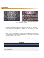
$ODUPWHVWV
7HVW
([SHFWHGUHVXOW
7XUQWKHE\SDVVVZLWFKWRWKH%<3$66SRVLWLRQ
³%\SDVVPRGHDFWLYH´DODUP
7XUQRIIWKH,QYHUWHU$&,QSXWEUHDNHU
,QYHUWHU$&LQSXWEUHDNHURIIDODUPQRFKDQJHLQ$&RXWSXWYROWDJH
7XUQRIIWKH,QYHUWHU$&2XWSXWEUHDNHU
,QYHUWHU$&RXWSXWEUHDNHURIIDODUPSRZHUWRORDGVLVRII
3XOORXWRQHLQYHUWHUPRGXOH
$VVXPLQJWKHQXPEHURIPRGXOHVLVVHWFRUUHFWO\LQWKH,QYHUWHUV!
6HW2XWSXWZHESDJHWKHFRPPXQLFDWLRQORVWDODUPVKRXOGDSSHDU
'RF%5HY'
28. At this point there should be no alarms present. Investigate and correct any alarm issues.
a. You will see a “communication” alarm if the number of installed inverters do not match the number of
modules set in the Inverters -> Set Output menu.
b. You will also get an alarm if the inverter input breaker is OFF, the inverter AC output breaker is OFF, or
the MBS is in the BYPASS position.
29. Test the functionality of various module alarms and controls.
30. Perform a system load test. Power up the equipment, one at a time. If possible, add heater or light bulb
loads to increase the load temporarily.
31. Turn off the inverter AC input breaker to perform a full load test from DC power.
3.12
Inverter Remote On/Off (Optional)
The AMPS80 HP inverters can be remotely activated or stopped (stand-by mode).
•
In a typical multi-shelf system, the remote ON/OFF can be connected on any shelf.
•
The voltage present on Terminal 1 and 3 is +5 V (galvanically insulated).
•
Do NOT connect an external voltage on terminal 1, 2, or 3. Maximum wire size is 16 AWG (1 mm²)
•
Use 3 wires, from a C NO/NC relay contact to control this function.
)XQFWLRQDOWDEOHIRUUHPRWH212))IXQFWLRQ
6WDWH
3LQ
3LQ
2SHQ
2SHQ
&RPPHQW
6\VWHPZRUNLQJQRUPDOO\
,QYHUWHUPRGXOHRXWSXWVZLWFKHGRII
&ORVH
2SHQ
$&RXWSXW/('RII
'&LQSXW/('LOOXPLQDWHGJUHHQ
$&LQSXW/('LOOXPLQDWHGJUHHQ
2SHQ
&ORVH
6\VWHPZRUNLQJQRUPDOO\
&ORVH
&ORVH
6\VWHPZRUNLQJQRUPDOO\
•
The inverter does not change its operating status if both transitions are not detected.
•
State 3 should be implemented by default.
•
Changing the status of these inputs from (State 3 -> State 2 -> State 3) forces the inverter modules to
start running without the T2S.
'RF%5HY'
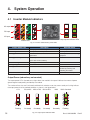
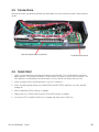
4. System Operation
4.1 Inverter Module Indicators
$&RXWSXW
'&LQSXW
$&LQSXW
2XWSXWSRZHULQGLFDWRU/('V
6WDWXV/('V
)LJ,QYHUWHUPRGXOHVWDWXVSRZHU/('V
,QYHUWHU6WDWXV/('
'HVFULSWLRQ
5HPHGLDODFWLRQ
2))
1RLQSXWSRZHURUIRUFHGVWRS
&KHFN$&LQSXW
3HUPDQHQWJUHHQ
$&,QSXW2.QRUPDORSHUDWLRQ
1RQHUHTXLUHG
)ODVKLQJJUHHQ
,QYHUWHU2.EXWFRQGLWLRQVDUHQRWZLWKLQQRUPDO &KHFNXSVWUHDPDQGVXUURXQGLQJ
SDUDPHWHUV
HTXLSPHQW
)ODVKLQJJUHHQRUDQJHDOWHUQDWLQJ
5HFRYHU\PRGHDIWHUERRVW
:DLWIRUDZKLOH
,QVKRUWFLUFXLWFRQGLWLRQ
3HUPDQHQWRUDQJH
6WDUWLQJXSPRGH
:DLW
)ODVKLQJRUDQJH
0RGXOHVFDQQRWVWDUW
,QVHUW76FRQWUROFDUG
)ODVKLQJUHG
5HFRYHUDEOHIDXOW
:DLWRUDWWHPSWWRFOHDUIDXOW
FRQGLWLRQE\UHPRYLQJDQG
UHLQVHUWLQJWKHPRGXOH
3HUPDQHQWUHG
1RQUHFRYHUDEOHIDXOW
6HQGPRGXOHEDFNIRUUHSDLU
Output Power (redundancy not counted)
The output power LEDs (located on the right side of the module’s front panel indicate the amount of power
(percentage of rated power) provided by the module.
The number of bars that are illuminated combined with whether or not they are on steady or flashing indicate
the output power level or overload condition as shown in the figure below.
WR
WR
WR
2YHUORDG
)ODVKLQJ
2QVWHDG\
2QVWHDG\
2QVWHDG\
2QVWHDG\
)ODVKLQJ
)LJ2XWSXWSRZHULQGLFDWRU/('V
'RF%5HY'
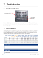
4.2 T2S Inverter Control Card
The CXC unified system controller monitors and manages inverter modules by communicating with the T2S
inverter control card. The T2S may be useful in troubleshooting inverter alarms.
LEDs 1 through 3 on the front panel of the T2S indicate the following alarm conditions:
•
Major Alarm LED
•
Minor Alarm LED
•
User-selectable Alarm (with T2S)
All alarms are qualified in Minor Alarm except those configurable by T2S.
0DMRUDODUP/('
0LQRUDODUP/('
8VHUVHOHFWDEOHDODUPZLWK76
86%SRUW
)LJ76IURQWSDQHO
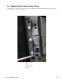
'RF%5HY'
$FFHVVWRORFNLQJODWFK7RUHPRYH76
IURP,QYHUWHUVKHOILQVHUWDVPDOOÀDW
VFUHZGULYHUDQGJHQWO\SUHVVXSRQWKH
ODWFKWKHQSXOORXWWKH76
4.3 Using the CXC Unified System Controller
The CXC controls the AMPS80 HP system and allows the user to set wide variety of parameters regarding the
alarms and operational functionality of the rectifier and inverter modules.
The following guide provides a brief overview of the controller; in-depth information can be found in the Technical Manual for the Cordex Controller Software.
Note: Section numbers referenced in this section correspond to the sections in the Technical Manual containing additional information on the referenced topic.
4.4
Software Overview
The CXC software enables control of an entire DC + AC power system via the CXC central touch screen user
interface or web based monitoring and control interface. The software also allows the user to control temperature compensation, auto equalization, remote access, and battery diagnostics.
)LJ&;&V\VWHPFRQWUROOHU
User interface
Located on the front panel of each model is a 160-x-160-pixel touch screen liquid crystal display. This graphical user interface (GUI) enables a person to interact with screen selectable items.
LED lights
Each CXC has three LEDs located on the front panel. These are used to display the alarm status of the power
system, CXC progress and status during startup, and file transfers.
Alarm conditions
The CXC illuminates the LED that corresponds to the system alarm status. The following show the corresponding alarm status for each LED color:
•
Green – OK, no alarms present
•
Yellow – Minor alarm is present (no major alarms)
•
Red – Major alarm is present.
•
Only one LED is illuminated at a time during alarm conditions.
'RF%5HY'
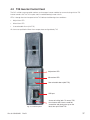
4.5
Connections
Remove two screws and fold the controller front panel down to access the communication and control connectors.
,QSXWDQGRXWSXWVLJQDOFRQQHFWLRQV
4.6
1.
&RQWUROOHU(WKHUQHWSRUW
Quick Start
Initiate a startup routine by switching on the power to the controller. This may be done by closing the
battery breaker. The controller will perform a short self-test as it boots up. Alarm alerts are normal. The
LEDs perform a scrolling pattern to indicate there is activity. Wait for the startup routine to finish.
2. Check and adjust alarms and control levels in the CXC’s submenus.
3. Check and adjust group settings in the INVERTERS and RECTIFIERS submenus; e.g. float, equalize
voltage, etc.
4. Verify COMMUNICATIONS settings as needed.
5. Program the CXC’s TEMP COMP and AUTO EQUALIZE settings as needed.
6. Test relay OUTPUT ALARM\CONTROLS as needed; e.g. Major Alarm, CEMF, etc.
'RF%5HY'
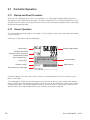
4.7
Controller Operation
4.7.1
Startup and Reset Procedure
When the CXC is powered-up or reset, it will first perform a 15-second self-test before displaying the Cordex logo and various identification messages. The three front-panel LED’s will illuminate temporarily, but will
extinguish after the system has finished its self-test. Next, the GUI will display the power system’s parameters
during Normal operating mode.
4.7.2
Normal Operation
This is the default-operating mode or “home page.” The GUI displays system status information and monitors
all input channels.
Active areas to tap and activate are noted below:
0RGHVWDWXV
$QDORJVLJQDOVGLVSOD\
5HFWL¿HUVLQIRUPDWLRQ
&RQYHUWHUWUHSRUWFDQDOVREH
DFFHVVHGYLDWKLVDUHD
$ODUPFRQGLWLRQLFRQ
3ULRULW\LFRQ
6RIWZDUHYHUVLRQ
$ODUPLQGLFDWLRQ
'DWHDQGWLPH
+RPHSDJHLFRQWDSWRORJLQ
Activation/Tapping: Each active area is touch sensitive and responds better to a stylus suited for this purpose; i.e. PDA type.
The Analog Signals Display on the home page will show two lines of text for system voltage and current by
default. Tap this active area to decrease the font size for four lines of text showing the system values and the
corresponding labels. The large font reappears after 20 minutes of inactivity (no user input); otherwise tap
again to enter a new window of operation or select a different active area as required.
'RF%5HY'
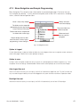
4.7.3 Menu Navigation and Sample Programming
Menu Navigation The sample screen shown below is presented upon login. From here, the user
may navigate (e.g. browse – as on a personal computer) each of the CXC’s menu items, including
alarms, controls and configuration items.
%DWWHU\YROWVDQG
ORDGFXUUHQWGLVSOD\
0RGHWHPSFRPSGLVSOD\
7KHIROGHUVFDQEHH[SDQGHG
LQGLFDWHGE\WKHSOXVVLJQVKRZQ
KHUHLIWKHUHDUH¿OHVLQVLGH
7DSRQWKHIROGHULFRQ
RUODEHOWRH[SDQG
)ROGHUVWKDWFDQEHFROODSVHGZLOO
EHVKRZQZLWKDPLQXVVLJQ
6OLGHUVDQGVFUROO
EDUVDUHXVHGIRU
QDYLJDWLRQ
%XWWRQVGLVSOD\KHUHIRUDGGL
WLRQDOIXQFWLRQVVXFKDVORJRXW
SURJUDPPLQJRUVDYHFKDQJHV
)LJ1DYLJDWLRQVFUHHQ
Option to Logout
Via the Option button, a pop-up window enables the user to logout of the menu navigation screen and return
to the home page. Follow the on-screen prompts to log out
Option to save
Saving in menu navigation (Supervisor only) will result in a prompt (pop-up window) to appear; e.g., “Save
Complete” when the settings are downloaded. Follow the on-screen prompts to save or discard changes.
Auto-logout time out
After 20 minutes of inactivity (no user input), the CXC will automatically logoff the user. The CXC will discard
any unsaved changes made by the user while logged in the system and return to Normal Operation mode.
Backlight time out
After one minute of inactivity (no user input), the CXC will automatically turn off the LCD backlight.
'RF%5HY'
4.7.4
Web-accessed Features
This section describes the additional web page features for Inverter system. See the CXC Software manual
for a complete description of the Cordex functionality.
Scope
These instructions explain the interconnection and operation of Alpha Technologies’ Cordex Controller with
Inverter Support. To aid the user with operation, frequent reference is made to the Cordex Software manual
(current revision).
The functionality of the CXCU is the same as the existing Alpha CXC system controller. A basic understanding of Ethernet, TCP/IP, SNMP, RS-485, and CAN bus functionality is required.
Product overview
The CXC is an integrated Alpha Cordex Controller designed to provide universal control for Alpha Group
products; in particular, AMPS80 HP systems using inverters and Alpha Cordex rectifiers.
The CXC has Ethernet capability that supports a web interface and SNMP for customer access to the equipment it is monitoring.
The CXC also has a CAN bus for communication with the Cordex rectifiers and other peripheral equipment.
Refer to the Cordex Software manual for details.
Inverter monitoring and control
Refer to the Cordex Software manual Chapter 6: Menu Structure, Programming and Adjustments.
The Inverter menu category consists of inverter alarms, signals and settings. Parameters can be accessed
such as the number of acquired inverters, output voltage/power, and source position.
Other features include: Input source, Inventory update,Inverter locate, Group assignment, Inverter firmware
upgrade, Major and minor alarms.
)LJ,OOXVWUDWLRQRIZHELQWHUIDFHZLQGRZVDPSOHKRPHSDJH
'RF%5HY'
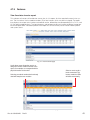
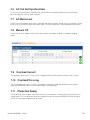
4.7.5
Features
View live status inverter report
This submenu of Inverters will enable the user to view, in a list report, all of the acquired inverters in the system. The first column lists the module numbers (ID) of the inverters; which may be re-assigned. The report
then displays the unique serial number and module version, followed by the corresponding AC In, DC In, and
AC Out group mapping values. The input frequency and temperature of each inverter completes the top portion of the report table. The bottom portion of the report lists all the currently active inverter module specific
and system alarms.
)LJ9LHZOLYHVWDWXVSDJH
$SXOOGRZQPHQXDOORZVWKHXVHUWRUH
DVVLJQWKHLQYHUWHUPRGXOHQXPEHULQWKH
UHSRUWIRUH[DPSOHWRFRUUHVSRQGZLWKLWV
SK\VLFDOORFDWLRQRQWKHVKHOI
6HOHFWLQJDPRGXOHQXPEHUWKDWLVDOUHDG\
XVHGZLOOVZDSWKHWZRPRGXOHV
6HOHFWDURZWRVHQGD
ORFDWHFRPPDQG7KH
LQYHUWHUPRGXOH
V/('V
ZLOOEOLQNPRPHQWDULO\
)LJ9LHZOLYHVWDWXV²LQYHUWHUVSDJH
'RF%5HY'
4.7.6
View Group Status
This submenu of Inverters will enable the user to view the grouping of input sources and inverter output that
share unique operating parameters per group – see Group Mapping.
6OLGHUVDQG
VFUROOEDUV
DUHXVHGIRU
QDYLJDWLRQ
)RXUJURXSVZLOO
VXSSRUWDWKUHH
SKDVHLQSXWSOXV
RQHPRUH
(LJKWJURXSVZLOO
VXSSRUW'&LQSXW
VRXUFHV
)LJ9LHZJURXSVWDWXVZLQGRZ²LQYHUWHUVSDJH
(LJKWJURXSVZLOOVXS
SRUWXSWRWZRVHWVRI
WKUHHSKDVHRXWSXW
SOXVWZRPRUH
'RF%5HY'
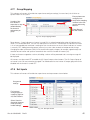
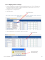
4.7.7
Group Mapping
This submenu of Inverters will enable the supervisor to configure settings (via menu items) for all of the acquired inverters in the system.
(QVXUHSKDVHVDUH
FRQ¿JXUHGFRU
UHFWO\EHIRUHPDSSLQJ
$PDWUL[RIEXW
LQYHUWHUVLQWKHQHZ
WRQVDOORZWKH
JURXSVDQGWXUQLQJ
VXSHUYLVRUWRPDS
WKHPRQ
HQDEOHGLVDEOH
WKHLQYHUWHU
V
DVVLJQPHQWSHU
JURXS
3RZHU%XWWRQV
8VHZLWKFDXWLRQ
)LJ*URXSPDSSLQJZLQGRZ
Power buttons – Green indicates an inverter is turned ON. An amber/orange/yellow color will indicate the inverter is in a recoverable error. The user can attempt to turn on the unit. The red color will indicate the inverter
is in an irrecoverable error and there is nothing the user can do to turn on the unit. Black indicates an inverter
is manually OFF. Adding/removing groups (columns) may take a few seconds to incorporate the change.
Changing the radio style buttons (rows) will also take time to apply changes; for example, approximately two
seconds for one inverter and up to ten seconds for the maximum number of inverters (32).
If there are inverters mapped to a column, disabling a column will be prevented and a warning message will
be displayed.
All inverters must be turned OFF to enable the AC Output Groups column buttons. The AC Output Groups of
an inverter in the ON state cannot be changed. The radio buttons for that inverter AC output group will remain
disabled until the inverter is turned OFF.
4.7.8 Set Inputs
This submenu of Inverters will enable the supervisor to set the parameters shown below:
6HHJHQHUDO
VHWWLQJV
)RULQYHUWHUV
FKDQJHVDSSO\RQ
DSDJHE\SDJHED
VLVVHOHFW6XEPLW
6HOHFW&DQFHOWR
GLVFDUGDOOFKDQJHV
PDGHLQFOXGLQJ
LQYDOLGVHWWLQJV
)LJ6HWLQSXWZLQGRZ
'RF%5HY'
0RGLI\LQJWKH$&RXWSXWYROWDJHRUIUHTXHQF\ZLOOYRLGWKHUHJXODWRU\DSSURYDORIWKHV\VWHP
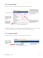
4.7.9
Set Output
This submenu of Inverters will enable the supervisor to modify the following parameters:
&$87,21
0RGLI\LQJWKH$&RXWSXWYROWDJHRUIUHTXHQF\ZLOOYRLGWKHUHJXODWRU\DSSURYDORIWKHV\V
WHP
Number of modules – The value is the number to be acquired by the CXCU. An invalid setting will result in
an alarm condition: Inverter Comms Lost; i.e., the number of modules must agree with the actual number of
inverters mapped to that particular group.
•
Redundancy – Defines the number of inverters to consider redundant.
•
Phase shift – Assigns a phase shift (in degrees) to the AC output group.
•
Nominal Output Voltage – Sets the target output AC voltage and must be used with caution; the devices
connected to the inverters could sustain damage due to irregular AC voltage.
Ensure that the Phase Shift is set correctly before mapping inverters in the new groups and turning them on.
)RULQYHUWHUVFKDQJHV
DSSO\RQDSDJHE\
SDJHEDVLVVHOHFW
6XEPLW
6HOHFW&DQFHOWR
GLVFDUGDOOFKDQJHV
PDGHLQFOXGLQJ
LQYDOLGVHWWLQJV
$QLQYDOLGVHWWLQJIRUDQ\FRQ
¿JXUDEOHSDUDPHWHUZLOOEH
LQGLFDWHGZLWKDUHGH[FODPD
WLRQPDUN
+RYHULQJWKHPRXVHRQWKH
H[FODPDWLRQPDUNUHYHDOVWKH
HUURUPHVVDJH
0RGLI\ZLWKFDXWLRQ
WKHGHYLFHVFRQQHFWHG
WRWKHLQYHUWHUVFRXOG
VXVWDLQGDPDJHGXHWR
LUUHJXODU$&YROWDJH
)LJ6HWRXWSXWZLQGRZ
'RF%5HY'
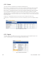
4.7.10
General Settings
This submenu of Inverters will enable the supervisor to set the parameters shown below:
$QLQYDOLGVHWWLQJIRUDQ\FRQ
¿JXUDEOHSDUDPHWHUZLOOEHLQ
GLFDWHGZLWKDUHGH[FODPDWLRQ
PDUN+RYHULQJWKHPRXVHRQ
WKHH[FODPDWLRQPDUNUHYHDOV
WKHHUURUPHVVDJH
9DOXHRURQO\
)RULQYHUWHUVFKDQJ
HVDSSO\RQDSDJH
E\SDJHEDVLVVHOHFW
6XEPLW
0RGLI\ZLWKFDXWLRQWKHGH
YLFHVFRQQHFWHGWRWKHLQYHUWHUV
FRXOGVXVWDLQGDPDJHGXHWR
LUUHJXODU$&YROWDJH
6HOHFW&DQFHOWR
GLVFDUGDOOFKDQJHV
PDGHLQFOXGLQJ
LQYDOLGVHWWLQJV
)LJ*HQHUDOVHWWLQJVZLQGRZ
The Free Running Frequency min./max setting is determined by the General Settings value. If AC input is present,
the AC output will synchronize; however an irregular AC voltage could damage the inverters.
4.7.11
Manage Config File
This submenu of Inverters will allow the user to upload an inverter configuration file.
%URZVH«WRORFDWH
¿OH2QFHVHOHFWHG
FKRRVHKHUHWRVHQG
WKH¿OHWRWKHLQYHUWHU
V\VWHP
)LJ0DQDJHFRQILJILOHZLQGRZ
'RF%5HY'
4.7.12
Alarms
The Inverter submenu will enable the user to configure the following alarms:
Major fail count – The controller activates this alarm when the number of failed inverters equals or exceeds
the user-configured threshold and clears when the number of failed inverters falls below the threshold.
Minor fail count – The controller activates this alarm when the number of failed inverters equals or exceeds
the user-configured threshold and clears when the number of failed inverters falls below the threshold.
Communications lost – The controller activates this alarm when the controller loses communications with any
one inverter and clears when communications resume. The number of inverters must be correctly identified in
the Set Output menu.
AC input fail – The controller activates this alarm when the main AC input of the inverter is lost.
(Inverter) alarm – The controller activates this alarm when any individual or system alarm condition is detected.
)LJ&RQILJXUHDODUPVZLQGRZ
4.7.13
Signals
The Signals submenu will enable the user to access inverter signals for all of the acquired inverters in the
system. The following signals can be used for logging and equation building.
)LJ6LJQDOVLQYHUWHUVZLQGRZ
'RF%5HY'
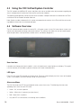
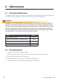
4.8
4.8.1
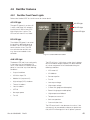
Rectifier Features
Rectifier Front Panel Lights
Refer to the Cordex CXRF 48-1.8 kW manual for further details.
AC LED light
$&/('OLJKW
The top LED (green) is on when AC
is within valid range. AC voltage is
invalid if the AC Mains Low or AC
Mains High alarm is active. The
LED turns off when AC has failed.
'&/('OLJKW
$ODUP/('OLJKW
DC LED light
The middle LED (green) is on when
the rectifier is delivering power to
the load. The LED will flash when
communication is lost. The LED
turns off when the rectifier is off;
e.g., when commanded via the
controller.
)LJ&RUGH[&;5)9UHFWLILHU
ALM LED light
The bottom LED (red) is on continuously
in the event of an active Module Fail
alarm; if the module is unable to source
power as a result of any of the following
conditions:
•
Output fuse blown
•
AC Mains Input Fail
•
Module fail (ramp test fail)
•
High voltage (OVP) shutdown
•
Thermal shutdown
•
Local shutdown
•
UPF fail
•
No output power
•
Fan fail.
The LED will flash (~2Hz) when a minor alarm is detected; if the modules output capability has been reduced
or a minor component failure is detected during the
following conditions:
•
VAC meter fail
•
AC foldback
•
Remote equalize
•
Fan fail
•
Low output voltage
•
High output voltage
•
Current limit (programmable option)
•
Power limit (programmable option)
•
High temperature foldback
•
Temperature sense fail
•
Soft start operation
•
Communications lost.
The LED remains off in the absence of an alarm. If the
unit output is not connected to a battery or parallel rectifier, the LED will extinguish if no AC power is present.
'RF%5HY'
4.8.2
LED Activity During Rectifier Software Upload
When a rectifier software upload is in progress, the LEDs will behave in a distinctly different way to indicate
new rectifier software is being transferred from the CXC.
When a rectifier data transfer is in progress, all three LEDs will flash in a sequence lasting 1.5 seconds. When
the last LED is lit, the sequence is repeated beginning at the first LED.
4.8.3 LED Activity During Rectifier ‘Locate Module’ Command from
Controller
When the ‘locate module’ command has been received from the CXC, the LEDs will behave in another distinct fashion so that the rectifier is easier to visually identify among adjacent rectifiers.
This state is entered when commanded via the CXC. The LEDs will flash in a ping-pong pattern repeating
every 2 seconds.
The ping-pong pattern lights each LED sequentially. After the last LED is lit, each LED is lit in reverse sequence. When the first LED is lit, the pattern repeats. The effect makes it appear as if the light is bouncing
between the first and last LED.
4.8.4
True Rectifier Module Fail Alarm
The power modules have a “true” fail alarm. This provides a true indication of the power module’s ability to
source current. When the module’s output current drops below 2.5% of the rated output a low output current
condition is detected and the Module Fail detection circuit is activated. This circuit momentarily ramps up the
output voltage to determine if the module will source current. If no increase in current is detected, the Module
Fail alarm is activated. The module will test once every 60 seconds for the condition until current is detected.
Output voltage ramping will cease upon detection of Current1. A minimum 2.5% load is required to avoid the
Ramp Test Fail alarm; this can typically be provided with the parallel system battery. Activation of this alarm
could indicate a failed module or a failed load.
For Cordex rectifier systems without batteries (or with a very light load; below 2.5% of rated output) it is
recommended that the ramp test be disabled to avoid nuisance alarms. The Ramp Test feature is enabled/
disabled via the CXC menu item: Rectifiers, Configure Settings.
'RF%5HY'
4.8.5 Mapping Alarms to Relays
1.
Connect a computer to the controller. Refer to the controller software manual. The 48 V DC power must
be switched on before the controller can operate. Provide either DC power on the main DC1 or DC4
connections or switch on at least one rectifier.
2. Navigate to Alarms > Configure Alarms.
3. Select Digital Inputs.
6HOHFW'LJLWDO$ODUPV
4. Select the desired relay. In this example K7 and K8 are available.
6HOHFWGHVLUHGUHOD\
,IWKLVSRSXSDSSHDUV
VHOHFWDQRWKHUUHOD\
'RF%5HY'
5. Submit changes after selection is made.
$IWHUFKDQJHVKDYH
EHHQPDGHSUHVV
6XEPLW&KDQJHV
6. Accept changes.
3UHVV$FFHSW
7.
Hook up control wires
to the selected relay.
+RRNXSZLUHVWRVHOHFWHGUHOD\
'RF%5HY'
5.
Tools Required
5HTXLUHG7RROV
6HUYLFH0DLQWHQDQFH
&RPPLVVLRQLQJ
7RUTXHZUHQFK
;
;
3KLOLSVVFUHZGULYHU
;
;
ÀDWKHDGVFUHZGULYHUZLGWKKHDG
;
ÀDWKHDGVFUHZGULYHUZLGWKKHDG
;
6PDOOÀDWKHDGVFUHZGULYHUZLGWKKHDG
;
KH[GULYHU
;
KH[GULYHU
;
FRPERZUHQFK
;
ÀDWJHDUUDWFKHW
;
FRPERZUHQFK
;
ÀDWJHDUUDWFKHW
;
FRPERZUHQFK
;
;
ÀDWJHDUUDWFKHW
;
UDWFKHWH[WHQVLRQ
;
UDWFKHWH[WHQVLRQ
;
UDWFKHWVRFNHW
;
UDWFKHWVRFNHW
;
UDWFKHWVRFNHWH[WHQGHGQHFN
;
UDWFKHWVRFNHW
;
UDWFKHWVRFNHWH[WHQGHGQHFN
;
UDWFKHWVRFNHW
;
UDWFKHWVRFNHWH[WHQGHGQHFN
;
PPFRPERZUHQFK
;
PPÀDWJHDUUDWFKHW
;
$OOHQNH\RQDUDWFKHWVRFNHW
;
;
$OOHQNH\RQDUDWFKHWVRFNHW
;
;
)ODVKOLJKWRUWURXEOHOLJKW
;
;
&URVVRYHU(WKHUQHWFDEOH
;
;
6WUDLJKWWKURXJK(WKHUQHWFDEOH
;
;
&RPSXWHUZLWK(WKHUQHWSRUWDQG,QWHUQHW([SORUHURUODWHU
;
;
7UXH506GLJLWDOPXOWLPHWHU
;
;
2WKHU5HFRPPHQGHG7RROV
6HUYLFH0DLQWHQDQFH
1HHGOHQRVHSOLHUV
;
6LGHFXWWHUV
;
:LUHVWULSSHU$:*WR$:*
;
([DFWRNQLIH
;
0HDVXULQJWDSHZLWKLQFKHVDQGFP
;
6FLVVRUV
;
5XEEHUPDOOHWGLDPHWHU
;
'RF%5HY'
&RPPLVVLRQLQJ
6.
6.1
Maintenance
Preventive Maintenance
This equipment requires regular maintenance. The maintenance must be done by qualified service personnel
only. Contact Alpha Technologies at 1-888-462-7487 for any assistance with maintenance.
:$51,1*
:$51,1*+,*+92/7$*($1'6+2&.+$=$5'8VHH[WUHPHFDUHZKHQZRUNLQJLQ
VLGHWKHHQFORVXUHVKHOIZKLOHWKHV\VWHPLVHQHUJL]HG'RQRWPDNHFRQWDFWZLWKOLYHFRP
SRQHQWVRUSDUWV6WDWLFHOHFWULFLW\PD\GDPDJHFLUFXLWERDUGVLQFOXGLQJ5$0FKLSV$OZD\V
ZHDUDJURXQGHGZULVWVWUDSZKHQKDQGOLQJRULQVWDOOLQJFLUFXLWERDUGV(QVXUHUHGXQGDQW
PRGXOHVRUEDWWHULHVDUHXVHGWRHOLPLQDWHWKHWKUHDWRIVHUYLFHLQWHUUXSWLRQVZKLOHSHUIRUP
LQJPDLQWHQDQFHRQWKHV\VWHP¶VDODUPVDQGFRQWUROVHWWLQJV
7DVN
&OHDQYHQWLODWLRQRSHQLQJV
PRQWK
,QVSHFWDOOFDEOHFRQQHFWLRQVUHWRUTXHLIQHFHVVDU\
\HDU
9HULI\DODUPFRQWUROVHWWLQJV
\HDU
9HULI\DODUPUHOD\RSHUDWLRQ
\HDU
9HULI\FLUFXLWEUHDNHURSHUDWLRQ
\HDU
6.2
1.
,QWHUYDO
Fan Replacement
Shut off the unit and unlock the power module.
2. Slide the module out of the shelf and wait two minutes for the module capacitors to discharge.
3. Disconnect the fan power wires from the module.
4. Note the direction of the airflow and remove the fan from the front panel.
5. Install the replacement fan following the preceding steps in reverse order.
'RF%5HY'
6.3 Removing T2S Inverter Control Card
To release the T2S from the shelf, insert a small flat screwdriver in the square hole under the USB port and lift
up the lock pin. Then pull out the module..
,QVHUWVFUHZGULYHU
DQGOLIWXS
'RF%5HY'
6.4 Surge Suppression Replacement
1.
Turn off the inverter input breaker.
:$51,1*
7KHUHPD\VWLOOEHOLYHSDUWVLQVLGHWKHV\VWHPDQGVKRFNKD]DUGVPD\EHSUHVHQWWKURXJK
RXWWKLVSURFHGXUH
5HSODFHDEOHSDUWV
2. Remove the wiring access panel.
$OSKDSDUWQXPEHU
3. Pull out the surge suppression
module.
4. Replace the module with one of the
same type.
'HVFULSWLRQ
6XUJHVXSSUHVVLRQUHSODFHPHQWPRGXOH
UHGVWULSH/LQH*URXQGN$UDWLQJ
6XUJHVXSSUHVVLRQUHSODFHPHQWPRGXOH
JUHHQVWULSH1HXWUDO*URXQGN$UDWLQJ
6XUJHVXSSUHVVLRQ
5HGVWULSH /*
*UHHQVWULSH 1*
6.4.1
Service Entrance Grade Surge Suppression Replacement
Front and left side access may be required to properly service the service entrance grade TVSS located
behind the CXCR control panel.
:$51,1*
7KHUHPD\VWLOOEHOLYHSDUWVLQVLGHWKHV\VWHPDQGVKRFNKD]DUGVPD\EHSUHVHQWWKURXJK
RXWWKLVSURFHGXUH
Make sure the spare parts are available on site.
5HSODFHDEOHSDUWV
$OSKDSDUWQXPEHU
'HVFULSWLRQ
$0367966SKN$UDWLQJSHUSKDVH7966RSWLRQRQO\
$0367966SKN$UDWLQJSHUSKDVH7966RSWLRQRQO\
$0367966SKN$UDWLQJ7966RSWLRQRQO\
'RF%5HY'
Side Access Replacement
1.
Turn off the inverter input breaker.
2. Remove the side access panel.
3. With the proper tools, reach in and remove
the screws holding the surge suppression
assembly.
4. Replace the module with an Alpha service
entrance grade surge suppression
assembly.
%ROWVKROGLQJVXUJH
VXSSUHVVLRQDVVHPEO\
Front Access Replacement
1.
Turn off the inverter input breaker.
2. Remove the screw securing the CXCR unit.
3. Remove the 4 mounting screws that hold
the CXCR to the chassis.
4. Pull the CXCR out and to the left. Do not
remove any of the wires from the CXCR
5. Dangle CXCR unit gently.
6. With the proper tools, reach in and remove
the bolts holding the surge suppression
assembly.
7.
Replace the module with an Alpha service
entrance grade surge suppression
assembly.
%ROWVKROGLQJVXUJH
VXSSUHVVLRQDVVHPEO\
'RF%5HY'
6.5
Fuse Replacement
For hybrid systems equipped with rectifiers, there are two fuses located behind the rectifier shelves (see
photo below). These fuses are sized to blow only if there is a wiring fault in the system. These fuses must only
be replaced by a qualified service person.
1.
Turn the rectifier breakers off
2. Disconnect the battery feeds to the AMPS unit.
:$51,1*
7KHUHPD\VWLOOEHOLYHSDUWVLQVLGHWKHV\VWHPDQGVKRFNKD]DUGVPD\EHSUHVHQWWKURXJK
RXWWKLVSURFHGXUH
3. For a 75 kVA AMPS unit: Remove the Left Side panel. For any other system: Remove all the 2U blanking
plates below the Rectifier shelves.
4. Remove the ¼-20 nut holding the fuse to the fuse holder/bracket (594-110-13). Use a 7/16 socket or
wrench.
5. Remove the ¼-20 screw and ¼-20 nut holding the wire to the fuse. Use a 7/16 socket or wrench.
6. Replace the fuse with a fuse of the same rating and type:
5HSODFHDEOHSDUWV
$OSKDSDUWQXPEHU
'HVFULSWLRQ
)XVH
)XVH
)XVH
'RF%5HY'
6.6 Synchronization After Maintenance or Repair
Implement the following sequence before switching the unit from bypass mode to inverter mode.
1.
Switch on the inverter input breaker. Wait for the inverters to synchronize to the line, and for all status
LEDs to turn green.
2. Switch on the inverter output breaker.
3. If present, switch the internal bypass switch to AMPS80 HP system. If present, switch the external bypass
switch to AMPS80 HP system.
'RF%5HY'
7.
Troubleshooting
7.1
Non Recoverable Error
,QYHUWHUVWDWXV/('V
2XWSXWSRZHU
VWDWXV/('V
The status LEDs illuminate permanently red when a non recoverable error occurs. Thanks to its double input
port, the AMPS80 HP inverter module will actually stop when either the output stage is non recoverable or
when both input stages are faulty. Generally, a non-recoverable error cannot be erased and the module must
be returned for repair.
7.2
Recoverable Error
A recoverable error is a kind of protection that acts when, some parameters exit temporarily from their proper
limit range. Stopping the module or removing it from its slot and plugging it back in may solve the problem.
For more detailed diagnostics, use the Ethernet port of the CXCR to view the alarm description. See Alarm
descriptions below. The inverter alarms can be found in Inverters > View Live Status.
'RF%5HY'
7.3 No Ethernet Communication
For a direct connection to the CXCR, verify that you are using a cross over cable, that your wireless connection is turned off, and that your local area network connection is set up as shown below.
Reset the CXCR by using the LCD touch screen as shown below:
3UHVV!
3UHVV³5HVHW´
Press the “reset now” pop up when it appears. To reset the T2S, remove it from the system, then hook it back
up.
'RF%5HY'
7.4
System Saturated
The system saturated alarm defaults to 80% load on the non redundant inverters. To remove this alarm, add
more inverters or reduce the amount of redundant units.
7.5 AC Secondary Source Lost
The AC Secondary alarm happens when the DC is removed from the system and when settings in the group
mapping screen are incorrect.
&OLFNWRUHPRYH
&OLFNWRDGG
'RF%5HY'
7.6 AC Out Not Synchronized
AC out not synchronized alarm happens when the input phase or frequency does not match the output
phase or frequency when AC input is present.
7.7 AC Mains Lost
The AC mains lost happens when the AC input does not meet the correct voltage, phase, or frequency. When
the AC main is lost the UPS goes into inverter mode. This alarm sometimes is accompanied by other alarms.
7.8
Manual Off
The Manual off alarm happens when one or more inverters have been turned off in the group mapping
screen.
7.9
Overload Current
The overload current alarm is an alarm that is triggered when the UPS provides more than 100% current.
7.10
Overload Too Long
The Overload too long alarm is an alarm that happens when the UPS provides overload current up to its
maximum period of time and shuts the inverter down to avoid damage.
7.11
Phase Not Ready
Phase not ready alarm happens when the inverter thinks it should be in a certain phase and the input to it is
another phase. This can be correct either by changing the input wiring to the AMPS80 HP or by changing
the phase in the group mapping settings screen.
'RF%5HY'
8.
System Specifications
0RGHO
$036
$036
$036
$036
,QSXW2XWSXW3KDVH
9SK
9SK
9RU
9RU
9SROH
9SROH
1RPLQDO2XWSXW3RZHUPD[
WR9$
WR9$
WR9$
WR9$
2XWSXW3RZHUUHVLVWLYHORDG
WR:
WR:
WR:
WR:
0D[LPXP2XWSXW&XUUHQW
$UPVSKDVH
$UPVSKDVH
$UPVSKDVH
$UPVSKDVH
0D[QRRI9$:
LQYHUWHUPRGXOHV
0LQQRRI9$:
LQYHUWHUPRGXOHV
7HFKQRORJ\
7ZLQ6LQH,QYHUWHU76,HDFKPRGXOHKDV'&LQSXW$&LQSXW
6WDWLF6ZLWFK
1RWUHTXLUHGHDFKPRGXOHKDVRZQVWDWLFVZLWFK
(I¿FLHQF\
$&WR$&'&WR$&IURPWRIXOOORDGUHVLVWLYH
:DYHIRUP
3XUHVLQHZDYH
2XWSXW3RZHU)DFWRU
7UDQVIHUWLPH
PV
:DUUDQW\
\HDUV
,QYHUWHU0RGXOH$&2XWSXW
1RPLQDO9ROWDJH$&
9
9ROWDJH$FFXUDF\
)UHTXHQF\
+]6DPHDVLQSXWIUHTXHQF\
,QYHUWHUIUHTXHQF\DFFXUDF\
7+'UHVLVWLYHORDG
7UDQVLHQWORDGUHFRYHU\WLPH
PV
6RIWVWDUWWLPH
V
0D[FUHVWIDFWRUDWQRPLQDO
SRZHU
6KRUWFLUFXLWRYHUORDGFDSDFLW\
[,QIRUPVHFLQ(3&PRGH$&LQSXW
6KRUWWHUPRYHUORDGFDSDFLW\
IRUVHFRQGV
3HUPDQHQWRYHUORDGFDSDFLW\
'RF%5HY'
,QYHUWHU0RGXOH$&,QSXW
1RPLQDO9ROWDJH$&
9ROWDJH5DQJH
,QSXW3RZHU)DFWRU
)UHTXHQF\
6\QFKURQL]DWLRQ5DQJH
9
XVHUDGMXVWDEOH
!
+]
+]
,QYHUWHU0RGXOH'&,QSXW
1RPLQDO9ROWDJH
9ROWDJH5DQJHPD[
0D['&LQSXWFXUUHQW#9GF
0D['&LQSXWFXUUHQW#9GF
9ROWDJH5LSSOH
9GF
9GFXVHUDGMXVWDEOH
$$$$
$$$$
P9GEUQF
8QL¿HG6\VWHP&RQWUROOHUZLWK6103
&RQWURO0RQLWRULQJ
'LVSOD\
&RPPXQLFDWLRQ3RUWV
&RQ¿JXUHFRQWURODQGPRQLWRU,QYHUWHU5HFWL¿HUPRGXOHVYLD,QWHUQHW
([SORUHUDQGRQZDUGV
/&'7RXFKVFUHHQGLVSOD\[SL[HOV
2.0DMRU0LQRUFRORU/('GLVSOD\
:HEEDVHG*8,YLD(WKHUQHW
5-(WKHUQHW3RUW
56&UDIW3RUW
560RGHP3RUWRSWLRQDO
&RQWUROOHU,2
9ROWDJH,QSXWV
7HPSHUDWXUH,QSXWV
&XUUHQW,QSXWV
%LYROWDJH,QSXWV
'LJLWDO,QSXWV
5HOD\2XWSXWV
(QYLURQPHQWDO6SHFL¿FDWLRQV
2SHUDWLQJ7HPSHUDWXUHIXOOORDG
6WRUDJH7HPSHUDWXUH
5HODWLYH+XPLGLW\
2SHUDWLQJ$OWLWXGH
7KHUPDO'LVVLSDWLRQ3HU0RGXOH
WR&WR)
WR&WR)
8SWRQRQFRQGHQVLQJ
8SWRPIWDERYHVHDOHYHO
%78KULQ$&WR$&PRGH%78KULQ'&WR$&PRGH
0HFKDQLFDO6SHFL¿FDWLRQV
6\VWHP'LPHQVLRQV
'[:[+PPLQ
6\VWHP:HLJKWZLWKRXWPRGXOHV
NJOE
7RWDO:HLJKWZLWKPRGXOHV
NJOE
,QYHUWHU0RGXOH'LPHQVLRQV
'[:[+PPLQ
,QYHUWHU0RGXOH:HLJKWNJOE
PP[PP[PP[[
NJOE
NJOE
PP[PP[PP[[
NJOE
$JHQF\&RPSOLDQFH
&6$
8/
'RF%5HY'
&
8/,VVXH
VKHOYHVDQGPRGXOHV
8.1 Module Location Relative to System Wiring
ϭ
ϯ
Ϯ
ϰ
'&IHHGVIRULQYHUWHUV
N9$SKDVHV\VWHPV
2SWLRQDO'&
EUHDNHULQSXWV
2SWLRQDO'&
EUHDNHULQSXWV
N9$SKDVHV\VWHPV
ϭ
ϯ
Ϯ
ϰ
'&IHHGVIRULQYHUWHUV
%ODQNSDQHO
,QYHUWHUVIRU$&SKDVH/
,QYHUWHUVIRU$&SKDVH/
,QYHUWHUVIRU$&SKDVH/
,QYHUWHUVIRU$&SKDVH/
,QYHUWHUVIRU$&SKDVH/
%ODQNSDQHOV
,QYHUWHUVIRU$&SKDVH/
5HFWL¿HURXWSXWWR'&
5HFWL¿HURXWSXWWR'&
5HFWL¿HURXWSXWWR'&
5HFWL¿HURXWSXWWR'&
ϭ
ϯ
Ϯ
ϰ
'&IHHGVIRULQYHUWHUV
,QYHUWHUVIRU$&SKDVH/
N9$VSOLWSKDVHV\VWHPV
2SWLRQDO'&
EUHDNHULQSXWV
2SWLRQDO'&
EUHDNHULQSXWV
N9$VSOLWSKDVHV\VWHPV
ϭ
ϯ
Ϯ
ϰ
'&IHHGVIRULQYHUWHUV
%ODQNSDQHO
,QYHUWHUVIRU$&SKDVH/
,QYHUWHUVIRU$&SKDVH/
,QYHUWHUVIRU$&SKDVH/
%ODQNSDQHOV
%ODQNSDQHOV
5HFWL¿HURXWSXWWR'&
5HFWL¿HURXWSXWWR'&
5HFWL¿HURXWSXWWR'&
5HFWL¿HURXWSXWWR'&
'RF%5HY'
8.2 Specifications for 48/120 Inverter Module
*HQHUDOVSHFL¿FDWLRQV
(0&LPPXQLW\
(1
(0&HPLVVLRQ
(1&ODVV$)&&9)53DUWFODVV$
6DIHW\
,(&8/,VVXH
&RROLQJ
)RUFHG$LU
07%)
KUV
(I¿FLHQF\W\SLFDO
(QKDQFHG3RZHU&RQYHUVLRQ
2Q/LQH
$&2XWSXW3RZHU
1RPLQDO
9$
5HVLVWLYH/RDG
:
2YHUORDG&DSDFLW\VKRUW
#V
2YHUORDG&DSDFLW\SHUPDQHQW
1RPLQDO
9
5DQJH9GF
WR9
1RPLQDO&XUUHQW#9GF
$
0D[LQSXWFXUUHQWV
$
9ROWDJH5LSSOH
P9
$&,QSXW6SHFL¿FDWLRQV
1RPLQDOYROWDJH$&
9DF
9ROWDJHUDQJH$&
WR9DFDGMXVWDEOH
3RZHUIDFWRU
!
)UHTXHQF\UDQJHVHOHFWDEOH
+]
)UHTXHQF\7ROHUDQFH
+]$GMXVWDEOH
$&2XWSXW
1RPLQDO$&
9DF$FFXUDF\
)UHTXHQF\
+]6DPHDVLQSXWIUHTXHQF\LQ(3&PRGH
)UHTXHQF\DFFXUDF\
7UDQVLHQWORDGUHFRYHU\WLPH
PV
7UDQVIHU3HUIRUPDQFH
0D[LPXP9ROWDJHLQWHUUXSWLRQ
V
7RWDO7UDQVLHQWYROWDJHGXUDWLRQ
V
(QYLURQPHQWDO
2SHUDWLQJ7HPSHUDWXUH
WR&
6WRUDJH7HPSHUDWXUH
WR&
+XPLGLW\
8SWRQRQFRQGHQVLQJ
(OHYDWLRQ
0
0LVFHOODQHRXV
'LPHQVLRQV
58+[PP:[PP'
:HLJKW
NJOE
'RF%5HY'
8.3 Specifications for 48-1.8 kW Rectifier
5HFWL¿HU0RGXOH,QSXW9ROWDJH2XWSXW&XUUHQW3RZHU
$&,QSXW9ROWDJH
5HFWL¿HUVKHOYHV
0D[RI5HFWL¿HU
0RGXOHV
0D['&RXWSXW9$
&XUUHQW$GF
$GF
9DF
$GF
3RZHU0RGXOH2XWSXW
9ROWDJH
WR9GFZLWKLQUDWHGOLPLWV
&XUUHQW
$PD[LPXP#9GFQRPLQDOLQSXW
a$#9GF9DFLQSXW
3RZHU
:PD[LPXP#QRPLQDOLQSXW
a:#9DFLQSXWGHUDWHGOLQHDUO\WR:#9DF
6WDWLF/RDG5HJXODWLRQ
'\QDPLF/RDG5HJXODWLRQ
%HWWHUWKDQIRUDQ\ORDGFKDQJHZLWKLQUDWHGOLPLWV
%HWWHUWKDQIRU±±ORDGVWHS
>RXWSXWVKDOOUHFRYHUWRVWDWLFOLPLWVZLWKLQPV@
6WDWLF/LQH5HJXODWLRQ
'\QDPLF/LQH5HJXODWLRQ
+ROGXS7LPH
7LPH6WDELOLW\
7HPSHUDWXUH6WDELOLW\
%HWWHUWKDQIRUDQ\FKDQJHLQLQSXWYROWDJHZLWKLQUDWHGOLPLWV
%HWWHUWKDQIRUDQ\FKDQJHLQLQSXWYROWDJHZLWKLQUDWHGOLPLWVRXWSXW
YROWDJHVKDOOUHFRYHUWRVWDWLFOLPLWVZLWKLQPV
!PV
SHU\HDU
SSP&RYHUWKHRSHUDWLQJUDQJH
+HDW'LVVLSDWLRQ
%78SHUKRXUSHUUHFWL¿HUPRGXOH
(OHFWULFDO1RLVH
G%UQ&YRLFHEDQG
P9UPVN+]WR0+]ZLGHEDQG
P9SSN+]WR0+]
P9SVRSKRPHWULF
$FRXVWLF1RLVH
(0,
G%D#PIW#&)
)&&3DUW&ODVV%
'RF%5HY'
9.
Spare Parts
5HFRPPHQGHGVSDUHSDUWV
3DUWQXPEHU
'HVFULSWLRQ
$,0LQYHUWHUPRGXOHN9$N:
,QYHUWHUEODQNLQJPRGXOH
,QYHUWHUEODFNSODVWLFIURQWDVVHPEO\
,QYHUWHUIDQ
&RUGH[&;&5FRQWUROOHU
76LQYHUWHUFRQWUROOHUFDUGEODFN
6XUJHVXSSUHVVLRQUHSODFHPHQWPRGXOHUHGVWULSH/LQH*URXQGN$UDWLQJ
6XUJHVXSSUHVVLRQUHSODFHPHQWPRGXOHJUHHQVWULSH1HXWUDO*URXQGN$UDWLQJ
:
5HFWL¿HUEODQNLQJSODWH
&RUGH[N:UHFWL¿HUPRGXOHK\EULGRSWLRQRQO\
)XVH$LQOLQHK\EULGRSWLRQRQO\
5HFWL¿HUIDQK\EULGRSWLRQRQO\
$0367966SKN$UDWLQJSHUSKDVH7966RSWLRQRQO\
$0367966SKN$UDWLQJSHUSKDVH7966RSWLRQRQO\
$0367966SKN$UDWLQJ7966RSWLRQRQO\
'RF%5HY'
10.
Certification
About CSA and NRTL
CSA (Canadian Standards Association also known as CSA International) was established
in 1919 as an independent testing laboratory in Canada. CSA received its recognition as an
NRTL (Nationally Recognized Testing Laboratory) in 1992 from OSHA (Occupational Safety
and Health Administration) in the United States of America (Docket No. NRTL-2-92). This
was expanded and renewed in 1997, 1999, and 2001. The specific notifications were posted
on OSHA’s official website as follows:
•
Federal Register #: 59:40602 - 40609 [08/09/1994]
•
Federal Register #: 64:60240 - 60241 [11/04/1999]
•
Federal Register #: 66:35271 - 35278 [07/03/2001]
When these marks appear with the indicator “C and US” or “NRTL/C” it means that the
product is certified for both the US and Canadian markets, to the applicable US and Canadian standards. (1)
Alpha rectifier and power system products, bearing the aforementioned CSA marks, are
certified to CSA C22.2 No. 950 and UL 1950, or CSA/UL 60950.
As part of the reciprocal, US/Canada agreement regarding testing laboratories, the Standards Council of Canada (Canada’s national accreditation body) granted Underwriters
Laboratories (UL) authority to certify products for sale in Canada. (2)
Only Underwriters Laboratories may grant a licence for the use of this mark, which indicates
compliance with both Canadian and US requirements. (3)
NRTLs capabilities
NRTLs are third party organizations recognized by OSHA, US Department of Labor, under the NRTL program.
The testing and certifications are based on product safety standards developed by US based standards
developing organizations and are often issued by the American National Standards Institute (ANSI). (4)
The NRTL determines that a product meets the requirements of an appropriate consensus-based product
safety standard either by successfully testing the product itself, or by verifying that a contract laboratory has
done so, and the NRTL certifies that the product meets the requirements of the product safety standard. (4)
Governance of NRTL
The NRTL Program is both national and international in scope with foreign
labs permitted.
'RF%5HY'
11.
Warranty
Alpha Technologies Limited (ATL) warrants its products to be free from defects in material and workmanship
for a period of two (2) years from the date of purchase. ATL obligation under this warranty is limited to the
repair or replacement, at its sole discretion, at the ATL factory or ATL Authorized Service Center, of any defective product. This warranty does not cover any failure of the unit caused in whole or in part by any cause
or causes external to the unit. Repair or replacement does not extend the original warranty period. Parts
furnished under this warranty may be new or factory-remanufactured.
Registration
This warranty is only available to the original end user of the product. Registering the product will automatically increase the length of the original warranty by 3 months at no additional cost. Please register your product
online at www.alpha.com/productregistration.
Extended Warranty
Registered purchasers may extend the warranty period for up to 3 additional years at any time during the
original warranty period at the then prevailing rate of ATL for such warranty extension. Registered purchasers
may be eligible to purchase other units, accessories, parts or services at discounted rates, including battery
upgrade or replacement, during the coverage period. Please contact us at 1-888-462-7487 to discuss your
service needs.
Limitation of Liability
This warranty is the purchaser’s sole remedy and is expressly in lieu of any other warranty, expressed or
implied, including any implied warranty of merchantability or fitness for purpose.
In no event shall ATL be liable for any indirect, incidental, special or consequential damages. In no case will
the liability of ATL under this warranty exceed the value of the unit provided.
'RF%5HY'
This page has deliberately been left blank
'RF%5HY'
This page has deliberately been left blank
'RF%5HY'
Alpha Technologies Ltd.
7700 Riverfront Gate
Burnaby, BC V5J 5M4
Canada
Tel: +1 604 436 5900
Fax: +1 604 436 1233
Toll Free: +1 800 667 8743
Alpha Technologies Inc.
3767 Alpha Way
Bellingham, WA 98226
United States
Tel: +1 360 647 2360
Fax: +1 360 671 4936
Alpha Industrial Power Inc.
1075 Satellite Blvd NW,
Suite 400
Suwanee, GA 30024
United States
Tel: +1 678 475 3995
Fax: +1 678 584 9259
Alpha Energy
1628 W Williams Drive
Phoenix, AZ 85027
United States
Tel: +1 602 997 1007
Fax: +1 623 249 7833
Alpha Technologies GmbH
Hansastrasse 8
D-91126
Schwabach, Germany
Tel: +49 9122 79889 0
Fax: +49 9122 79889 21
Technologies Argus
First de Mexico
Anatole France Num. 17
Colonia Polanco
11560, México D.F.
Tel: +52 55 5280 6990
Alpha Technologies Europe Ltd.
Twyford House Thorley
Bishop’s Stortford
Hertfordshire, CM22 7PA
United Kingdom
Tel: +44 1279 501110
Fax: +44 1279 659870
Alphatec Ltd.
339 St. Andrews St.
Suite 101 Andrea Chambers
P.O. Box 56468
3307 Limassol, Cyprus
Tel: +357 25 375 675
Fax: +357 25 359 595
Alpha TEK ooo
Khokhlovskiy Pereulok 16
Stroenie 1, Office 403
Moscow, 109028
Russia
Tel: +7 495 916 1854
Fax: +7 495 916 1349
Alpha Technologies
Unit 504, 5/F,
Fourseas Building
No 208-212 Nathan Road
Kowloon, Hong Kong
Tel: +852 2736 8663
Fax: +852 2199 7988
Alpha Innovations Brasil
Avenida Ibirapuera,
2120 – Cj 76
Moema - 04028-001
Santos SP, Brazil
Tel: +55 11 2476 0150
Fax: +55 11 2476 0150
Alphatec Baltic
S. Konarskio Street 49-201
Vilnius, LT-03123
Lithuania
Tel: +370 5 210 5291
Fax: +370 5 210 5292
Visit us at www.alpha.ca
Due to continuing product development, Alpha Technologies reserves the right to change specifications without notice.
Copyright © 2010 Alpha Technologies. All Rights Reserved. Alpha® is a registered trademark of Alpha Technologies.