1
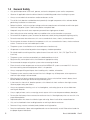
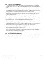
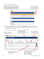
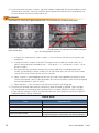
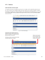
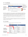
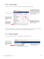
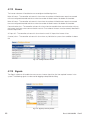
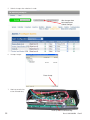
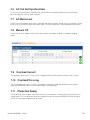
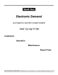
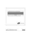
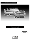
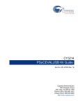
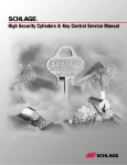
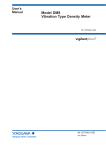
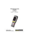
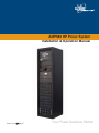
4.7.7
Group Mapping
This submenu of Inverters will enable the supervisor to configure settings (via menu items) for all of the acquired inverters in the system.
(QVXUHSKDVHVDUH
FRQ¿JXUHGFRU
UHFWO\EHIRUHPDSSLQJ
$PDWUL[RIEXW
LQYHUWHUVLQWKHQHZ
WRQVDOORZWKH
JURXSVDQGWXUQLQJ
VXSHUYLVRUWRPDS
WKHPRQ
HQDEOHGLVDEOH
WKHLQYHUWHU
V
DVVLJQPHQWSHU
JURXS
3RZHU%XWWRQV
8VHZLWKFDXWLRQ
)LJ*URXSPDSSLQJZLQGRZ
Power buttons – Green indicates an inverter is turned ON. An amber/orange/yellow color will indicate the inverter is in a recoverable error. The user can attempt to turn on the unit. The red color will indicate the inverter
is in an irrecoverable error and there is nothing the user can do to turn on the unit. Black indicates an inverter
is manually OFF. Adding/removing groups (columns) may take a few seconds to incorporate the change.
Changing the radio style buttons (rows) will also take time to apply changes; for example, approximately two
seconds for one inverter and up to ten seconds for the maximum number of inverters (32).
If there are inverters mapped to a column, disabling a column will be prevented and a warning message will
be displayed.
All inverters must be turned OFF to enable the AC Output Groups column buttons. The AC Output Groups of
an inverter in the ON state cannot be changed. The radio buttons for that inverter AC output group will remain
disabled until the inverter is turned OFF.
4.7.8 Set Inputs
This submenu of Inverters will enable the supervisor to set the parameters shown below:
6HHJHQHUDO
VHWWLQJV
)RULQYHUWHUV
FKDQJHVDSSO\RQ
DSDJHE\SDJHED
VLVVHOHFW6XEPLW
6HOHFW&DQFHOWR
GLVFDUGDOOFKDQJHV
PDGHLQFOXGLQJ
LQYDOLGVHWWLQJV
)LJ6HWLQSXWZLQGRZ
'RF%5HY'