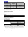
1
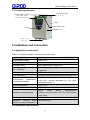
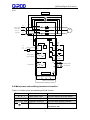
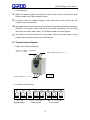
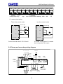
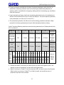
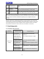
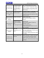
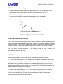
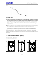
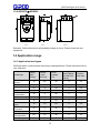
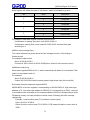
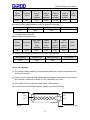
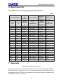
QDS Intelligent soft starter
Product manual
Please read the product manual
in detail before using the product.
l
QDS Intelligent Soft
Starter
Operation Manual
Shanghai Qirod Electric Science &Technology Co.,Ltd
III
QDS Intelligent Soft Starter
Pre-word
Thank you for choosing “QDS”series motor soft starter manufactured by Qirod. This
product is available for the soft starting and stops of three-phase squirrel cage motor.
Please read and understand the contents in this manual before use in order to apply
correctly.
Safety notice item
■ Please read this manual careful so as to realize the optimized
performace.Changing or setting parameters will have influence on the
functions and performance, So parameters of soft starter should be
changed by qualified (Professional) person in order to avoid problems.
Only qualified (Professional) technicians are allowed to install QDS soft
starter.
■ Please guarantee the power of motor and QDS soft starter is fitting.
Installation must be carried out according to user manual rules.
■
don’t connect the capacitor at the end of soft starter output, or else the
soft starter will be damaged.
■
Input and output copper wire lug of QDS series soft starter should be
packed with insulated rubber tape after installation
■
Keyboard control should be locked when remote control is enabled
■
The enclosure of soft starter should be grounded firmly.
■
Input power supply should be cut off while carrying out maintenance.
In spite of writing down this manual carefully, but Qirod can‟t guarantee this manual
without tiny mistake. The product described in this manual is subjected to change
regarding the technology and operation methods without notice. Please understand
that this point won‟t be taken in consideration in contract.
1
QDS Intelligent Soft Starter
Contents
Pre-word .................................................................................................................... 1
Contents..................................................................................................................... 2
1 Check related items before use ............................................................................... 4
1-1 Good arrival check .......................................................................................... 4
1-2 Product appearance ........................................................................................ 5
2 Installation and connection ...................................................................................... 5
2-1 Application environment .................................................................................. 5
2-2 Installation requirements ................................................................................. 5
2-3 Connection ...................................................................................................... 6
2-4 Main power and earthling terminal connection ................................................. 7
2-5 soft starter main circuit connection .................................................................. 9
2-6 Control terminal connection ........................................................................... 10
2-7 Terminal layout diagram ................................................................................ 11
2-8 Primary and secondary wiring diagram .......................................................... 12
2-9 Relay and remote control wiring .................................................................... 13
3 Running................................................................................................................. 13
3-1 Check preparation before running ................................................................. 13
3-2 Running method ............................................................................................ 13
4 Keyboard panel ..................................................................................................... 14
5 Basic function ........................................................................................................ 15
5-1 Code function setting ..................................................................................... 15
6 Detailed instruction of functions ............................................................................. 17
6-1 Code FE is used to set when the running output delay will activate. .............. 17
6-2 Code FC parameters modification enable function. ....................................... 18
7 Operation process ................................................................................................. 18
7-1 Modify setting parameters ............................................................................. 18
8 Help information .................................................................................................... 19
8-1 help information and Instruction ..................................................................... 19
9 Protection function................................................................................................. 20
9-1 Protection function instruction ........................................................................ 20
9-2 Protection functions setting............................................................................ 20
2
QDS Intelligent Soft Starter
9-3 Protection trip curves ..................................................................................... 22
10 Protection action.................................................................................................. 22
10-1 Protection action list .................................................................................... 22
11 Fault diagnostic ................................................................................................... 24
11-1 Problems and measures .............................................................................. 24
12 Starting mode ...................................................................................................... 26
12-1 Current limitation mode ............................................................................... 26
12-2 Voltage ramp starting .................................................................................. 26
12-3 Kick-off mode .............................................................................................. 27
12-4 Current ramp starting mode ......................................................................... 28
12-5 Dual closed-loop starting ............................................................................. 28
12-6 Soft stop ...................................................................................................... 28
12-7 Free stop ..................................................................................................... 29
13 Overall dimensions(mm) ................................................................................. 29
13-1 QDS005 to QDS055 .................................................................................... 29
13-2 QDS075 至 QDS320.................................................................................... 30
14 Application range................................................................................................. 30
14-1 Application load types.................................................................................. 30
15 RS485 Communication........................................................................................ 31
15-1 MODBUS Communication protocol.............................................................. 31
16 Spare parts list .................................................................................................... 36
16-1 QDS circuit accessory equipment and cable size: ....................................... 36
17 Appendix ............................................................................................................. 36
3
QDS Intelligent Soft Starter
1 Check related items before use
1-1 Good arrival check
After receiving the product you order, Please open the box and check all items below, if
some product problems exist or product is not in accordance with your type. Please
contact with the distributor or nearest office of QIROD.
1 Inspect the nameplate on the soft starter to confirm the model you ordered.
○
Type nameplate
Soft starter type
QDS
3
3: Three Phase 380V
Rated power:0.75 means 75kW
Product series:QIROD Soft starter
①
Check if there is any damage of appearance during transportation, such as cover
and bending of enclosure, damage or drop of components.
②
In addition to soft starter as well as including a operation manual and quality
certificate.
③
Please lift the enclosure when you remove soft starter, not lift the PCB board
cover, or else possibly cause damage of drop or human injury.
4
QDS Intelligent Soft Starter
1-2 Product appearance
Power supply input
(R、S、T)
Connect bypass contactor
(L21、L22、L23)
Control circuit terminal
Base
Communication port
Keypad
PCB control box
Connect
motor
(U、V、W)
2 Installation and connection
2-1 Application environment
Table 2-1-1means installation environment requirements
standard
Conform to national standard(GB14048.6-2008)
Three phase voltage
380V±15%
Frequency
50Hz
Available motor
three phase squirrel cage motor
No. of Starting
Defined by load, no more than 6 times/h is
suggested
Vibration
15g11ms
Anti-earthquake
Altitude below 3000m,vibration device below 0.5G
Environment
temperature,
working temperature
0-+40℃
without
derating,between
+40℃-60℃ ,current decreases by 1.2% while
temperature rises 1℃
Stock temperature
-25℃-70℃
Environment humidity
95% non-condensing or water drop
Maximum working altitude
below
1000m
without
derating,above
1000m,current decreases by 0.5% while altitude
rises 100m
Cooling method
Natural cooling
Maximum
working
angle
relative to vertical installation
No requirement
2-2 Installation requirements
5
QDS Intelligent Soft Starter
①
Soft starter should be installed vertically,reversed,angle or horizontal installation
are not allowed. The screws should be used to make soft starter fix on the firm
structure.
②
Soft starter will generate heating while runs, in order to make air pass, as shown
in 2-2-1, specified space should be left.
The heating will rise up, so soft starter is not allowed to install under the device
which is not withstanding the heat.
2-2-1
③
2-3 Connection
Please pay attention on each instruction below while wiring:
①
Main power has to connect with power terminal R、S、T, no phase sequence
requirement. If the power is wiring wrong, the soft starter will be damaged.
②
Earthling terminal must be earthed well, on the one hand protecting electric shock
or fire accident, on the other hand reducing noise.
④
Two ends of conductor should be dealt with crimping in order to guarantee
reliability of connection.
2-3-1 Basic wiring
6
QDS Intelligent Soft Starter
2-3-1
Main circuit
KM1
5
3
1
6
4
2
L23
L3
Power supply
Three phase
L2
380V AC
50/60 Hz
T
W
S
V
R
U
L22
M
L21
L1
Q1
FU
N
或
L3
KM1 全压输出
A1
A2
+DC12V
11
Instant
stop
12
Stop
S1
13
start
S2
Ue=
01
100%
02
03
Delay output
(programmable)
04
05
14
15
06
Fault output
07
09
08
10
17
Analog output
(DC 4-20mA)
19
Control circuit
16
Public
terminal
18
0V
485+ 485RS485 Communication
2-4 Main power and earthling terminal connection
Table 2-4-1 Main power and earthling terminal function
Terminal mark
Terminal name
Instruction
Main power input
Connect with three phase power
U、V、W
Soft starter output
Connect with motor
L21、L22、L23
Bypass connection
Connect with bypass contactor
Soft starter earthling
The enclosure of soft starter should
be earthed well
R、S、T
PE
7
QDS Intelligent Soft Starter
(1)
Main power input terminal (R、S、T)
1 Main power input terminal R、S、T should be connected through circuit breaker
○
or circuit breaker with earth leakage protection to three-phase AC power without
consideration of the phase sequence.
2 Controlling the running and stopping of soft starter through main power ON/OFF
○
is not allowed, please wait for power on of soft starter then select control
terminal or RUN or STOP key on panel to make soft starter start and stop.
③Don‟t connect with single-phase power.
(2)Soft starter output terminal (U、V、W)
① Soft starter output terminal should be connected with three-phase motor
according to correct phase sequence. If the rotation direction is not correct, just
exchange any two phases connection of U、V、W.
② Soft starter output should not connect with capacitor and surging absorber.
③ When the cable between soft starter and motor is long, the distributed capacitor
will generate major HF current which will cause over current trip of soft starter,
current leakage increasing and bad current display presion.So the suggested
connection length is not above 50m,
(3) Bypass connection(L21、L22、L23)
① Bypass connection terminal L21、L22、L23, should be connected with bypass
contactor, or else soft starter will be damaged. When soft starter finishes starting,
main power components (SCR) will be bypassed, meanwhile, bypass contactor
will work, so motor will run normally, Please make sure the correct phase
sequence.
(4)Soft starter earthling terminal(
PE)
① In order to guarantee safety and reduce noise, soft starter earthling terminal
should be earthed well. in order to prevent electric shock and fire accident,
metal enclosure and frame of eclectic device should be in accordance with
national electric rule requirements.
!
Danger
Make sure that the input phase No. and rated input voltage of soft
starter are conforming to AC power supply phase No. and voltage.
AC power supply can‟t connect to output terminal (U、V、W).
Bypass contactor should be connected and also the phase
8
QDS Intelligent Soft Starter
sequence is same with main power, or else possible damage
accident will be caused.
2-5 soft starter main circuit connection
电源
Three
3 相 phase
380V~50/60Hz
380V~50/60Hz
电源 3 相 380V~50/60Hz
Circuit breaker or leakage
circuit breaker
L23
R S T
L22
L21
1 3 5
Soft
With bypass
starter
Electromagnetic
(QDS)
contactor(KM)
2 4 6
U
V W
M
Three-phase asynchronous motor
9
QDS Intelligent Soft Starter
2-6 Control terminal connection
Control terminal function table 2-6-1. According to different function setting, control
terminal function and wiring will be different.
Terminal
name
Bypass
output
Terminal
mask
01、02
Function instruction
01,02 are closed to control bypass contactor after soft
starting finishing
KW
FU
01
02 A1
A2
L1
L3 或 N
Running
output
(delay)
03、04、05
03、04、05 are programmable relay outputs, delay time
will be set by code F4. Output function will be set by
code FE,they are NO/NC ,they will close when output
is valid,(NO capacity is 250V/5A, NC capacity is
250V/3A)
Fault
output
06、07、08
06、07、08 are programmable fault relay outputs,
they will be closed when faults occur or power off and
be open when power on.(contact capacity 250V/3A)
Analog
output
09、10
09 、 10 can measure current information which
fluctuates with load. Output 4-20mA, calibration value
400%, calculation formula: D=400/16(Ix-4). Ix is the
actual measured value (mA), D is motor current (%)
Instant
stop input
11
11 and common disconnecting will make motor stop
immediately.(or free stop)
Soft stop
input
12
12 and common disconnecting will make motor soft
stop.(or free stop)
Starting
input
13
common
14、15
communic
ation
16、17、18
PE
19
13 and common closing will make motor running.
Common terminal of input signal
Communication terminal which is used to connect lot
of motor, 16 is communication earthling.
earthling terminal
10
QDS Intelligent Soft Starter
(1) Input terminal
1
○
When the external control terminals are used for the function of start and stop,
please enable code FB as external control
2
○
If remote control is needed, suggest using (two lines) control mode, see P8:
2-9(two lines control mode)
3 Input terminal and common terminal of connection signal are generally closed/open
○
(ON/OFF), soft starter, motor and wiring will cause interference. So the wiring
should be a bit short (below 20m). The shielded cable should be applied.
4
○
The wiring of control terminal must keep away from main power cable, or else
possibly cause misacting because of interference.
2-7 Terminal layout diagram
(1)Main circuit terminal diagram
Connect bypass caontactor
(L21、L22、L23)
Power supply input(R、S、T)
PE
Connect motor(U、V、W)
(2)Control circuit terminal
01
02
Bypass output
03
04
05
06
Delay output
07
Fault output
11
08
QDS Intelligent Soft Starter
09
10
11
instant
analog output stop
12
13
14
15
16
17
stop
com
start communication earthing 485+
18
19
485-
PE
(3)control circuit wiring
Three lines control mode
two lines control mode
Instant stop
Instant stop
11
11
11
Stop
Stop
12
12
12
K
Start
13
Start
13
13
Public terminal
14、15
Public terminal
14、15
14、15
Control terminal cable 0.75-1.25mm2
It is under running when K is closed.
And it stops when K is open.
2-8 Primary and secondary wiring diagram
L1
L2
N or L1
L3
A1
Circuit
L21
Bypass
contact 1 3 5
or(KM)
breaker
L22
R
L23
(QF)
FU
S
T
Bypass
output
A2
01 02 03
2 4 6
11 12
U
V
Fault
output
Delay
output
04
05 06
07 08
13 14/15
W
A
M
Instant stop start public
stop
terminal
12
Analog output
DC 4-20mA
QDS Intelligent Soft Starter
2-9 Relay and remote control wiring
Diagram Relay control mode
Instant stop
Remote control mode
Instant stop
K
11
Stop
Stop
12
12
Start
Start
KA
KA
13
13
Public terminal
Public terminal
14、15
14、15
KS
KA
L
K
11
KA
N
KA
L
N
K is the often-closed point of other protects equipment like heat protector.
Ex-factory is short connected.
3 Running
3-1 Check preparation before running
Check preparation before running
①
Check if the wiring is correct, especially check that output terminals should
not connect with power, check if bypass contactor is connected well and
make sure that earthling terminal is earthed well.
②
Make sure that terminals or nude live part is not short-circuit or short-circuit
to earth.
③
After power switches on, keyboard panel will display Ready, meanwhile
ready lamp will be lighting.
3-2 Running method
■ Swathing on will display (Ready), and the ready indication lamp turns on, then
pressing the key will start the motor.
■
Input the rated current into parameter code FP according to motor nameplate.
13
QDS Intelligent Soft Starter
■
Check if the motor rotation direction is correct and running is normal after starting, if
the running is abnormal, pressing stop key to stop or cutting off main power if
necessary.
■
If the starting state of motor is not reasonable, please refer to P19 and P23 the
chapter of starting mode and application of soft starter for selecting adequate
mode.
■ Starting voltage code F0(voltage ramp mode)or current limitation code F5(current
limitation mode), elevate starting torque of motor.
■ After switching on soft starter, don‟t open the upper cover for fear of electric shocks.
■ Within commissioning, any abnormal phenomenon, such as abnormal noise,
smoking or odor occurs, power supply should be cut off immediately and verify the
reason.
■ After power on or starting, the fault indication lamp lights and HMI displays Errxx,
please Refer to P17 table to find the reason according to the fault code.
■ Pressing stop key or remote stop button can reset the fault state.
Note: when environment temperature is lower than -10°C, Please pre-heat after power
on for more than 30min before starting
4 Keyboard panel
Keyboard panel has abundant operation function, such as keyboard panel start and
stop, data confirmation and modification and also sorts of state confirmation functions
14
QDS Intelligent Soft Starter
Table 4-1-1 Operation key function
Key
name
Main function
Run key
Display READY, press this key for starting, and meanwhile display starting
state.
Stop
key
1、Display A000(current value) for normal running, press this key for
stopping. Display -0000 when soft stop.
2、This key can reset the fault state.
Setup
key
Indicate ready statusREADY. Press tjos key to enter into the menu and pre
ss the key again when it displays
F0:30. When the colon is flashing, then we can modify the parameter with
up or down key.
Mode
key
1、After modifying the parameters, pressing this key to store, displaying
GOOD and sounding twice mean the data have been stored well, press this
key again or stop key will exit.
2、Pressing this key will display power voltage.AC380 refer to:P14: 8-1
3、Keeping Pressing mode key will make setting parameters recover to
factory value.
Up and
down
key
1、 Entering the menu setting and using up and down key to modify
parameters,(when colon is not flashing, xx:xxx this key can be used to
modify function code. when colon is flashing, xx:xxx this key can be used to
modify data code)
2、During running, this key can be used to monitor running A current,
P(power),H thermal balance display of overload
■ When figure > „999‟, the last digit will delight to mean that the last digit will add „0‟.
■ Soft starter will have warning sound when Pressing key, or else this key is invalid.
■ The keyboard can be connected with external control panel,(installed outside of the
cabinet) connection wire distance is less than 3m.
5 Basic function
5-1 Code function setting
●Parameters setting code listed in following table
Code
Name
Code function setting
Factory
Set scope
value
15
Instruction
QDS Intelligent Soft Starter
F0
Initial voltage
30-80%
30%
F1
F2
Starting time
Soft stop time
2-60S
0-60S
16S
0S
F3
Starting delay
0-999S
0S
F4
Programmabl
0-999S
e delay
Starting
50-500%
current
limitation
Maximum
50-200%
working
current
Under voltage 40-90%
protection
Overvoltage 100-140%
protection
Starting mode
0-5
F5
F6
F7
F8
F9
FA
FB
FC
FD
FE
FF
FP
0S
280%
100%
80%
120%
1
Output
protection
enable
Control mode
0-4
4
0-6
1
Parameter
Modification
allowed
Communicati
on address
Programmabl
e output
Current
limitation
of
soft stop
Motor rated
current
0-2
1
0-63
0
0-19
7
20-100%
80%
1-99S
Rated
value
Valid for Voltage ramp mode: initial
voltage of current mode is 40%
Invalid for current limitation mode
Setting 0 is free stop. If one driving two
mode, please set as 0.
Using countdown mode to delay, setting
0 will not delay and start immediately.
Using for programmable relay output
Valid for current limitation mode: the
maximum current limitation is 400% for
voltage ramp mode
This is the percent of rated current
Protection will activate less than setting
value
Protection will activate more than setting
value
0 current limitation,1 voltage 2 kick
0ff+current limitation, 3 kick off
+voltage,4 current ramp,5 dual
closed-loop
0 Primary1 light load 2 standard 3 heavy
load 4 advanced
0 keyboard; 1 keyboard external control;
2 external control ;3 external control
+communication; 4 keyboard external
control +communication ;5 keyboard
+communication; 6 communication
See in detail P12
16
Used to communicate between multiple
soft starters with upper machine.
Running relay output(03,04 terminal)
setting
Detailed instruction P21
Used to input the rated current of motor
QDS Intelligent Soft Starter
FU
FL
Bypass
switching time
Three-phase
imbalance
protection
enable
0-3
3
3
0 imbalance disenable, phase loss
disenable; 1 imbalance disenable,
phase loss enable; 2 imbalance enable,
phase loss disenable; 3 imbalance
enable, phase loss enable
Note:1 Parameter F6 maximum working current means the maximum continual
running current calculated base on parameter FP, if the maximum running
current exceeds this value. The reverse time limit thermal protection will be
activated.
2 Staying setting state more than 2 mins without any pressing operation,
display will automatically exit from setting state.
3 Within soft start and soft stop period, No parameters can be set, for other
state all the parameters can be set.
4 Keeping pressing confirmed key (YES) after power on will make setting
parameters (excepting for FE) recover to factory value.
6 Detailed instruction of functions
6-1 Code FE is used to set when the running output delay will activate.
Programmable relay output will have two types work mode, namely programmable time
Sequence output and programmable state output.
(1) When Setting FE 0~4(10~14), programmable output works under time sequence
output, setting starting moment of output.
Shown as following table
FE Setting value
0(10)
1(11)
2 (12)
3(13)
4(14)
Programmable
output moment
When run
command is
given
When it is
starting
When
bypass is
closed
When stop
command is
given
When stop
is finished
■ This working mode includes a 999 seconds timer, set by F4, if F4 is not 0, the timer
will count according to the initial time set in FE. When the time is reached, the output
will change the state.
■ The reset time of this output will be in accordance with the time set in F4, delay
ending and staying in ready state for 1 second.
17
QDS Intelligent Soft Starter
■ Programmable time sequence output mode uses a starting process as control
period, if the motor restarts ,the previous programmable output process will be
automatically interrupted and programmable output process will be started again.
(2) Code FE=5~9, programmable output will be set as start output mode, the setting
working state is shown in following table.
FE setting value
Programmable
output moment
5 (15)
6(16)
7(17)
8(18)
9(19)
Fault output Running state Ready state Starting state Stop
state
The programmable output will be used to indicate the working state of soft starter,
FE=7 is factory value. which means that soft starter stays in ready state, for this
state, soft starter is ready to start motor; when the programmable output is fault
state which means motor fault(Err05、Err06、Err07、Err08、Err012、Err15),it is
different from the function of fault terminal ⑤、⑥. Running state is neither ready
state nor fault state, which includes start, bypass and soft stop.
■ When FE>9, reset state of the programmable output(③、④ external connection
terminal) will switch from NO to NC. Namely reversed direction output. The flexible
application of programmable output function can simplify peripheral logic control
circuit.
■
6-2 Code FC parameters modification enable function.
Parameters modification enable has three modes:
■
FC=0, except for FC, prohibited to modify any parameters
■
FC=1, prohibited to modify values of F4、F6、Fd、FE、FF、FU、FL.
■
FC=2, allowed to modify all the values of parameters
7 Operation process
7-1 Modify setting parameters
Power
on
Press ENT
key
Enter
code
selection
Press up and
down key
Press ENT
key
confirm
changing
code
select
function
code
18
Press up and
down key
modify
setting
scope
Press ENT
key
save
modified
data(exit)
QDS Intelligent Soft Starter
For example :( operation control mode is external terminal, namely code FB=2)
No.
Operation
display
1
Power on
2
Press ENT
F0:30
Enter function code selection state
3
Press up and
down key
Fb:01
Enter code FB (operation control mode)
function selection state.
4
Press ENT
Fb:01
Colon is flashing, means that the setting
scope can be changed
5
Press up and
down key
Fb:02
Means external terminal control
6
Press ENT
READY
GOOD
Instruction
QDS technology or ready state
Save modified data(exit)
Soft starter interior buzzer will sound when the keyboard is operated.
8 Help information
8-1 help information and Instruction
Help information will notice as following table
Display
Instruction
AC:XXX
3 bits digital voltage meter, used for monitoring
three-phase AC power voltage.
055-3
Notice that the type of this soft starter is 55kw-380/50Hz
H1:E05
Notice latest happened fault information Err05
H2:E01
Notice ever happened fault information Err10
H3:E06
Notice ever happened fault information Err06
....
......
H9:E00
Notice no fault information
UEr3.0
Notice the software of this product is Ver3.0
LXXX
Total Successful No. of starting
RUNXX
Previous soft starting time(no matter Succeed or not)
Recursive mode will be used for H1~H9 to store latest 9 fault messages.
19
QDS Intelligent Soft Starter
■ When they are not soft starting/soft stop state and not enter setting state, entering
help information is allowed, press ENT key and press up and down key to refer to
notice information.
■
Under help state, pressing ENT key or stop key to exit help state.
9 Protection function
9-1 Protection function instruction
QDS series soft starter has complete protection functions which will protect application
safari of soft starter and motor. For the detailed application, protection class and
protection parameters should be set correctly according to different application.
■ Soft starter overheat protection: The protection will activate when temperature rises
to 80℃±5℃.when the temperature decreases to 55℃ (lowest), overheat protection will
relieve.
■ Input phase loss protection delay time: <3s
■ Output phase loss protection delay time:<3s
■ Three phase imbalance protection delay time:<3s.the deviation of each phase
current more than 50%±10% will be set as benchmark. when the load current is 30%
lower than the rated current of soft starter. The standard of criterion deviation will
increase.
■ Starting over current protection time: Protection time table P15:9-2-1for continually
more than 5 multiples of code F5 (maximum working current) w
■ Running overload protection time: Code F5 (maximum working current) will be set as
the benchmark of anti-time thermal protection. Trip protection time curve (see 9-3-1)
■ Over low of power supply protection delay time: When the voltage of power is lower
than limited value 40%, protection action time <0.5s, or else less than the setting value,
the protection action time<3s.
■ Over high of power supply protection delay time: When the voltage of power is
higher than limited value 130%, protection action time <0.5s, or else more than the
setting value, the protection action time<3s.
■ Load short-circuit protection delay time<0.1s, current is more than 10 multiples of the
rated current of soft starter. This protection can‟t replace the fuse or short-circuit
protection device.
■ The time parameter above means from detecting the effective signal to send out trip
protection command, Time parameters are just for reference. If the protection functions
of soft starter can‟t comply with the user‟s requirements, so the specified protection
device is demanded i9n order to make sure the safety
9-2 Protection functions setting
In order to adapt to different applications, soft starter has 5 protection class, namely 0:
primary 1: light load 2: standard 3: heavy load 4: advanced, all are set by Code FA.
20
QDS Intelligent Soft Starter
■ Primary protection prohibits the function of external emergency stop terminal, at
same time, reserving overheat, short-circuit and input phase loss protection of
starting, which is available for emergency starting without considering any conditions.
Such as fire pump.
■ Light, standard and heavy load have complete protection function, the deference is
that the overload thermal curves of motor are different. The motor thermal protection
time parameters can refer to 9-2-1 and 9-3-1.
■ The advanced protection will follow more strict starting protection standard. Other
protection functions parameters are same with standard protection setting
Code FA setups different protection level and heat protection time. Please see the form
9-2-1 to setup of
Code FA
setting
Running
overload
protection
class
0
(primary)
No
1
2
3
4
Instruction
(light load) (standard ) (heavy load) (advanced)
2 class
10 class
20 class
10 class
Running
over
current
No
3 class
15 class
30 class
15 class
protection
class
Curre
Runn
nt tim
3 4 5 3 4 5 3 4 5 3 4 5 3 4 5
ing es
overl (I/Ie)
oad
trip Trip
time time 4.5 2.3 1.5 23 12 7.5 46 23 15 4.5 23 1.5 23 12 7.5
table (sec)
comply
with
IEC609474-2
standard
Calculated
base on 5
multiples
of Starting
current
Value in
table is
typical
value.
■ Please set code FP according to rated current on motor name plate or else , the
starting current and protection current will exist big deviation.
■ Motor current set in Code FP can‟t be less than 20% of rated current of soft starter.
When motor current set in Code FP is a little bit small, the sensitivity error of
protection trip action will increase.
21
QDS Intelligent Soft Starter
9-3 Protection trip curves
The motor thermal trip time curves complying with IEC60947-4-2 standard are as
following. 9-3-1
t(s)
10000
1000
100
30
20
10
10
1
0.5
2
1.12
1.5
2.0
2.5
3.0
3.5
4.0
4.5
5.0
5.5
6.0
6.5
7.0
I/I
7.5
Motor thermal trip time curves (thermal state)
10 Protection action
10-1 Protection action list
When soft starter is abnormal, the protection action will be active and trip immediately.
Alarm name displayed in LCD and related contents can refer to instruction in table
10-1-1.
22
QDS Intelligent Soft Starter
Table 10-1-1
display
instruction
Problem and treatment measures instruction
release
Under voltage, overvoltage or overheat and open
circuit of emergency terminal faults are emerging just
now, now is normal, Ready lamp is lighting, after
reset, soft starter
can be used to start motor.
Err00
fault
Err01
Open circuit of external Connect external stop terminal 7 and common
emergency
stop terminal 10 or connect to other NO contact of
terminal
protection device
Err02
Overheat of soft starter
Err03
Starting parameters setting is not suitable or the load
Starting time is more
is too heavy, power capacities is not enough and so
than 60sec
on.
Err04
Input phase loss
Check if existing input or main circuit fault, if bypass
contactor is blocked and keeps at close position and
id SCR is open circuit.
Err05
Output phase failure
Check if existing input or main circuit fault, if bypass
contactor is blocked and keeps at close position and
id SCR is open circuit.
Err06
Three
imbalance
Err07
Starting over current
Err08
Running
protection
Err09
Overflow
supply
Err10
Over high of power Check if input power supply voltage is low or
supply
parameter F8 setting is not suitable
Err11
Setting
error
Start over frequently or motor power and soft starter
power are not matched
phase Check if input three phase power supply and load
motor are normal
If load is over heavy or motor power and soft starter
power are not matched
overload If load is over heavy or code F6 and FP parameters
setting are not suitable.
of
power Check if input power supply voltage is low or
parameter F7 setting is not suitable
parameter Modify setting or holding Enter key for power on to
recover the factory value
23
QDS Intelligent Soft Starter
Check if load or SCR is short-circuit or load is over
heavy
Err112 load short-circuit
Err13
Automatic
wiring error
restart Check if external control terminal and stop terminal
are not connected according to 2 wires mode
Err14
Automatic stop wiring When external control mode is allowed, external stop
error
terminal is open circuit, so the motor can‟t start.
Note: some faults are interconnected, such as displaying Err02 soft starter overheats
which may be caused by starting over current or load short-circuits. So when checking
the fault, reasons should be considered completely so as to judge the fault point
precisely.
Attention: when motor is starting successfully by using soft starter, the running state
indication lamp in the panel will be lighting, that means bypass contactor is close, when
motor stops because of the open of bypass contactor, bypass contactor and related
wiring should be checked in order to make sure not mistake or misconduct.
11 Fault diagnostic
11-1 Problems and measures
Abnormal
phenomenon
Motor is not
rotating
Checking content
Adopted Measure
If wire layout is
abnormal or power
supply cables are
connected with input
terminal (R,S,T)
Please make sure right wiring,
Power on
Cut off power and power on again
If bypass contactor is
working well, 01 and
02 terminals has
signal.
Check the connection of bypass
contactor
Check connection of bypass contactor
coil
If keyboard has
abnormal display
Please read P17 protection action list
if motor is locked(if
load is too heavy)
Please release motor locking(reduce
load)
24
QDS Intelligent Soft Starter
Keyboard can‟t
be used to start
External control
can‟t be used to
start
Motor is rotating
and speed is not
changing
starting time is
over long
Starting time is
overshot
Suddenly stop
during running
If keyboard displays
emergency stop or
terminal is open or
code FB setting is
normal
No: if existing phase loss of power
supply, check incoming power supply
Yes: if 10 and 11, 12 are open. Check
external terminal wiring and set code
FB correctly.
If code FB is set as
external control
Terminal 14 and 11, 12 are open,
check external terminal wiring, set
code FB correctly and make sure FB is
external control.
If load is too heavy
please reduce load
Increase initial voltage or starting
current
Load is too heavy
Code is not setting
well
If motor type is normal
Reduce load
Set F0(initial voltage), F5(start ing
limitation current
)F1(soft starting time)
Please check type instruction manual
and nameplate
light load
Starting time is too
short
When load is light, the starting time is
less than setting value, it will be normal
when starting finishing.
Set code F1 starting time(current mode
is invalid)
Check external input
terminal
Check if terminal 11 and 14 are loosen
If connecting with external protector,
please check if NC contact is active.
Check if the external stop button wiring
is loosen
25
QDS Intelligent Soft Starter
12 Starting mode
12-1 Current limitation mode
Code F9 =0 is current limitation starting mode. Picture 12-1-1 shows the motor
current change curve for current limitation starting mode.I1 is the setting starting
current limitation value. When the motor starts, output voltage will increase fatly
until the motor current reaches the setting current limitation value and keep the
current value not more than setting value. Then following the gradual rising of the
voltage, motor will accelerate gradually. When the motor reaches the rated speed,
bypass contactor will close. Output current will go down to rated current or below
fatly, starting process will be finished.
② when the load is light or setting current limitation value is to high, so it is normal
that maximum starting current will possibly not reach the setting value. Current
limit mode is generally used for the application which requires the strict limit for
starting current.
①
12-1-1
I
I1
Ie
T
0
12-2 Voltage ramp starting
①
Code F9=1 (voltage) is voltage ramp mode. Picture 12-2-1 has shown the output
voltage wave of voltage ramp starting. Ui is the initial voltage of starting, when
the motor is starting, the motor current will not exceed 400% of rated current.
The output voltage of soft starter will rise up to UI quickly. Then the output
voltage will gradually rise up according to setting parameters of starting. Motor
will smoothly accelerate along with the rising of voltage. When voltage reaches
the rated value Ue, motor will achieve rated speed, then the bypass contactor
will close and the starting process will be finished.
26
QDS Intelligent Soft Starter
②
Starting time: t is the measured controlled parameter under standard
experimental condition according to standard load. QDS series soft starter will
use this parameter as benchmark, then by controlling the output voltage makes
the motor accelerate smoothly so that to finish the starting proccess.Not
controlling the time t by mechanical method no matter if acceleration of motor
has been smooth. For this reason, when the load is light, the starting time will be
less than setting time. It is normal as long as the starting is finished successfully.
Generally, voltage ramp starting mode will be suitable for the application which
requires non-strict starting current but high smooth starting.
U
12-2-1
Ue
UI
0
t
T
12-3 Kick-off mode
① Code F9=2 (kick-off+voltage ramp) or =3 (kick-off+current limitation) starting mode,
12-3-1 and 12-3-2 have shown output waveform of kick-off mode. For some heavy
load application, the motor can‟t start because of mechanical static friction, this
mode will be available. At the beginning of starting, applying high constant voltage
on motor and lasting for a while in order to overcome static friction of motor load to
make motor run. Then motor will start according to current limitation or voltage ramp.
② before using this mode, firstly choose non kick-off mode to start motor, if the motor
can‟t rotate because of high static friction, this mode will be chosen. Or else this
mode should be avoided to use in order to reduce the unnecessary impact current.
12-3-1
12-3-2
C
C
Un100%
Un100%
U1
U1
0
100ms
T
27
0
100ms
T
QDS Intelligent Soft Starter
12-4 Current ramp starting mode
① Code F9=4(current ramp mode)is the starting mode, 12-4-1 is the output current
waveform of current ramp starting mode.I1 is the starting time set in F1.
② Current ramp stating mode will make motor strong acceleration ability. It is available
for two poles motor, this mode will short starting time for some range.
12-4-1
I
I1
Ie
0
T1
T
12-5 Dual closed-loop starting
1
○
Code F9=5(dual closed-loop) is dual closed-loop starting mode. Dual closed-loop
mode of Voltage and current will adopt dual closed-loop control of voltage ramp and
current limitation. This mode is available for requiring both smooth starting and strict
current limitation; it adopts the prediction algorithm to estimate the motor work state.
2
○
The output voltage waveform of this starting mode will vary according to
different state of motor and load.
12-6 Soft stop
QDS series soft starter has two stop modes, namely soft stop and free stop.
① T is the soft stop time set in F2. For this mode, the power of motor will switch from
bypass contactor to SCR of soft starter. The output voltage of soft starter will gradually
decrease from full voltage to make motor speed reduce smoothly so as to avoid the
mechanical fluctuation until the motor stops running. The cut-off voltage of soft stop is
equal to the initial voltage of soft starting.
② Code F2=0 is soft stop mode. 12-6-1 is the output current waveform of soft stop
mode; Soft stop can reduce or eliminate water hammer of pump and reduce the impact
of big current for soft stop. This soft stop current limitation value is the percent
calculated base on starting current limitation.
28
QDS Intelligent Soft Starter
12-6-1
12-7 Free stop
1 Code F9=0(free stop) is free stop mode. For this stop mode, soft starter will accept
○
the stop command and cut off bypass contactor control signal and prohibit the SCR
output. The motor will gradually stop depending on load inertia. if one soft starter
drives N motors, set the code as this mode and avoid phase loss fault during the
output switching.
2 Generally, if no soft stop is needed, the free stop mode should be chosen to prolong
○
the life span of soft starter. Soft stop mode can prohibit the instant output
completely which will avoid the instant big current impact of special application
QDS series soft starter has six different starting modes, which will be available for
variable complicated motor and load. User can select soft starter according to different
application.
13 Overall dimensions(mm)
13-1 QDS005 to QDS055
161
216
264
249
162
Front
Side
29
Base
M5
QDS Intelligent Soft Starter
13-2 QDS075 至 QDS320
260
216
226
527
471
M8
正面
侧面
Front
底座
B ase
Side
正面
侧面
底座
正面dimensions will probably
侧面
底座
Remarks: Outline
change in future. Please
check the real
正面
侧面
底座
equipment.
14 Application range
14-1 Application load types
QDS soft starter could meet the most heavy load applications. Please see below list for
your reference.
Load type
Ramp
start
time(s)
Ramp
stop
time (s)
Initial
voltage
(%)
Voltage
start( Maxim
current limit
value)
Current
limit start
Centrifugal
pump
Ball mill
16
20
40
4
2.5
20
6
60
4
3.5
Fan
26
4
30
4
3.5
Light motor
16
2
30
4
3
16
4
40
4
3
Piston
compressor
Lift machinery
Crusher
Screw compre
ssor
Screw
conveyor
Heat pump
Screw
transportation
heat pump
6
10
60
4
3.5
16
2
50
4
3
16
10
50
4
3.5
16
2
40
4
3
20
10
40
4
2
20
10
40
4
2.5
16
20
40
4
3
30
QDS Intelligent Soft Starter
15 RS485 Communication
QDS series soft starter will connect with PC and PLC through interior RS485 standard
communication module to carry out serial communication.
The master can control the soft starter to run and stop, and monitor the running state of
soft starter and modify other function data. The detailed information of this
communication should refer to RS-485 operation manual.
The RS-485 communication of soft starter can be used to communicate with computer
for remote operation. Input run command and manage running state. Multiple soft
starter function code data will write in for one time so as to realize the simple operation
of the function code input.
Main functions:
1, run and stop command input
2, running state monitoring
3, real-time tracing (running information shown in table)
4, function code writes in and read out for one time, save into document.
The communication software needs to be consulted with our company.
15-1 MODBUS Communication protocol
15-1-1 Relative Modbus RTU communication protocol overview.
Modbus is series asynchronous communication protocol. The physic port is RS485.
Modbus is designed by modicum for PLC, which has the property of PLC. In modbus
control net, QDS can be treated as a PLC to be read and written. Start and stop
command, state information (current, fault) and function parameters will be reflected to
holding registers (4XXX).using PLC master to read and write to soft starter.
(1)Electric port
RS485 half-duplex
Communication parameter: bade rate: 9600; 8 bits data bit; no calibration; 1 bit stop bit
(2)communication data format
data format:
address code
function code
date zone
CRC calibrion
1 byte
1 byte
N bytes
2 bytes
15-1-2 related setting of soft starter
(1)Holding address
31
QDS Intelligent Soft Starter
Holding register address
Operation code
Holding register function
instruction
40001
06
control word
40002
03
state word
40003
03
*10 average current
40004
03
fault code
40256-40274
03&06
function code of soft starter
■ The registers unlisted are illegal ,can‟t read and write, or else the slave will report to
master a exception state code.
■ All the data addresses are referring to 4000, namely coil relay 40001 address is
0001, address of 402567 is 0100(hex)
(2)Available code
Soft starter is just supporting following code, if using other code will offer exception
case code 1
code
Function description
03
06
Read register
Write single register
Code 03 is just used for single word read.
(3)Register instruction
40001 command register
bit
value
description
0
1
soft starter starting
0
holding state
1
soft starter stop
0
holding state
2
0-1
make soft starter reset
3-15
0
no use
1
For example: slave address of soft starter is 02, master sends out 02 06 00 01 00 01, if
the command is activated normally, slave will return code 02 06 00 01 00 01. The
state register should be checked to make sure if the soft starter can start normally.
If existing fault, sending 02 06 00 01 00 04 to reset fault.
Register address 40002state register
32
QDS Intelligent Soft Starter
State register will reflect the state of soft starter, which is indicated by a word.
Bit
0
1
2
3
value
description
1
starting state
0
stop state
1
sunning state
0
stop state
1
soft stop state
0
stop state
1
fault state
0
normal state
4-15
No use
For example: read state register code 02 03 00 02 00 01
If soft starter is starting, the return code 02 03 02 00 01,
If soft starter existing fault, return code 02 03 02 00 08, and read fault type
according to 4.
40003 current average (hex)
This value reflects three phase actual current average of motor *10(including a
fractional part)
For example: read current
Send: 02 03 00 02 00 0
If current is 235A, return 02 03 02 09 2E(return value/10 is the actual current)
40004 fault code (hex)
When state register 40003 bit 3 is 1, which means that soft starter is in fault state. Fault
code is in accordance with 6.1.
For example:
Send: 02 03 00 04 00 01
If return 02 03 02 00 04.which means present input phase loss (fault code 04)
Soft starter function parameter register40XXX
40256-40274 is function registers, corresponding to 0X0100-0X0112, high order byte
address is 01, low order byte address is 0X00-0X12. Corresponding to F0-FL, they are
in accordance with code table 4.2.for example address 0X109 is corresponding to code
F9(starting mode), can read and write to these codes. Following will offer example
respectively:
Example 1 read function code F5 () limitation current value)
Send: 02 03 01 05 00 01
Return function code of read F5: 02 03 02 01 5E means limitation current value is
350%.
33
QDS Intelligent Soft Starter
Example 2 read function code FA (protection class)
Send: 02 03 01 0A 00 01
Return function code of read FA: 02 03 02 00 03 means that the protection class
read is 3
Example 3: Change function code 05 of the soft starter (start current) to be 250%
The master will send the code: 02 06 01 05 00 FA and soft starter return the code
: 02 06 01 05 00 FA. If the return value is 02 86 03, then it could not input any
data and probably the soft starter is under running.
15-1-3 Abnormal response
code
name
instruction
01
illegal function
02
illegal data address
If code can‟t execute, soft state will
not support
The data address received can‟t
execute. The address overflows
The data received can‟t execute
1 Parameters surpasses the
limitation
03
illegal data value
2 Parameters can‟t modify
3 Parameters can‟t modify when soft
starter is running
(1)illegal function code 01
Master inquiry message format:
Slave
addre
ss
Functi
on
code
High order
byte of
initial
address
Lower
byte of
initial
address
High order
of register
number
Low order
of register
number
0x01
0x08
0x00
0x80
0x00
0x00
CRC
check
This function code 0x08 is never used in this protocol, so slave will response:
slave address
function code
abnormal code
0x01
0x88
0x01
(2)illegal function code 02
Master inquiry message format:
34
CRC check
QDS Intelligent Soft Starter
Slave
address
Function
code
High order
byte of
initial
address
Lower
byte of
initial
address
High
order of
register
number
Low
order of
register
number
0x01
0x04
0x01
0x80
0x00
0x07
CRC
check
04 function code register address error, so slave will response:
slave address
function code
abnormal code
0x01
0x84
0x02
CRC check
(3)illegal function code 03
Master inquiry message format:
Slave
address
Function
code
High order
byte of
initial
address
Lower
byte of
initial
address
High
order of
register
number
Low
order of
register
number
0x01
0x04
0x00
0x80
0x01
0x80
CRC
check
04 function code register number error, so slave will response:
slave address
function code
abnormal code
0x01
0x84
0x03
CRC check
15-1-4 use attention
(1) The communication address, communication bade rate, check mode should keep
same with controller.
(2) If can‟t receive response data, please check parameter setting above, and check if
485 terminal connection is correct, if CRC calcification is correct.
(3) For multiple communications, please add a 120Ω resistor
(4) If connect with other Modbus device, please connect as following
Signal ground
GND
485+
485+
485-
485-
Modbus
Shielding to ground
35
QDS Intelligent Soft Starter
16 Spare parts list
16-1 QDS circuit accessory equipment and cable size:
(380V)
Motor parameter
Soft
starter
Circuit breaker
Electrom
agnetic
contactor
Model
specification
Model
specificatio
n(By-pass)
Copper core
gauge(mm)
Cable/Cop
per bar
Power
(kW)
Current
(A)
Model
specificati
on
5.5
11
QDS005
CM1-63/16
CJ20-16
2.5
7.5
15
QDS007
CM1-63/20
CJ20-16
4
11
21
QDS011
CM1-63/32
CJ20-25
6
15
18
QDS015
CM1-63/40
CJ20-40
10
18.5
34
QDS018
CM1-63/50
CJ20-40
10
22
42
QDS025
CM1-63/63
CJ20-63
16
30
54
QDS030
CM1-100/80
CJ20-63
25
37
68
QDS037
CM1-100/100
CJ20-100
35
45
80
QDS045
CM1-160/120
CJ20-100
35
55
98
QDS055
CM1-160/160
CJ20-160
35
75
128
QDS075
CM1-225/180
CJ20-160
50
90
160
QDS090
CM1-225/225
CJ20-250
30x3
115
190
QDS115
CM1-225/315
CJ20-250
30x3
132
236
QDS132
CM1-400/315
CJ20-400
30x3
160
290
QDS160
CM1-400/350
CJ20-400
30x5
200
367
QDS200
CM1-400/500
CJ20-400
30x5
250
430
QDS250
CM1-630/630
CJ20-630
40x5
280
470
QDS280
CM1-630/630
CJ20-630
40x5
320
547
QDS320
CM1-630/700
CJ20-630
40x5
400
725
QDS400
CM1-630/800
CJ20-1000
40x6
17 Appendix
Warranty and after-sales services
Thanks very much for choosing QDS soft starter manufactured by Shanghai QIROD
Electric Science & Technology Co., Ltd. The products are made under mature quality
management system. For your easy operation, we make our promise to warranty and
after-sales services in the below.
36
QDS Intelligent Soft Starter
1 Warranty
Warranty is 12months after purchase or 24months since the date on the nameplate.
Anyway, we will provide the repair with possible charge due to below reasons which
caused the fault.
1) Wrong operation
2) Mover standard operation range
3) Broken down based on falling down during the transportation
4) Earth quake, fire, wind, thunder, abnormal voltage and other natural disasters.
2 After-sales service
1) When it is under unstable status, please do the regular inspection. And then read
the operation manual and re-check again.
2) When the fault happens, please contact the distributor or contact the after-sales
office listed in the operation manual.
3) Within the warranty, the repair will be free due to our quality issue. But the user
has to correctly input all kinds of content in the warranty letter. Or we will charge the
necessary cost.
4) Over the warranty service, we will charge some cost if we can successful repair
the equipment.
3、Service promise
1) QDS series soft starter below 75kw (including) could be replaced without human
reason under one-year warranty. And the soft starter above 75kw will be promised to
free repair within one-year warranty without human reason.
2) We promise to offer technical support: we would like to send our technician to the
site to carry out commission & installation and offer free training to related technical
employee. (For the international customers, they have to afford the flight tickets,
local transportation cost and related accommodation)
3) We will reply to our customer within 24hours based on the kind request from our
customers.
37
QDS Intelligent Soft Starter
Warranty Letter of QIROD
Customer
name
Contact
Tel
Address
Fax
Model
Ex-factory
series no.
Supplier
Name
Purchase
date
Address
Fault date
Fault status
Application
Motor
____KW___ Pole
Model_____
When
Connective running/ acceleration/ deceleration/ power on/ others
Time display
Alarm display( )
Running
after reset
Possible/ impossible/ reset method/ keypad / terminal/
/supply others
Control
terminal
usage
01,02 03,04,05 06,07,08
16,17,18 19
Work time
Power off
keypad display(
09,10
Frequency
Y
N
)
Y
38
power
11 12 13 14,15
/
Abnormal
situation
around the
machine
voltage display(yes
Installation
room
N
Failure
record
Y/N
no )
Shanghai QIROD Electric Science & Technology Co.,Ltd
International sales branch:Shanghai FMZ Industry Co.,Ltd
Add:NO.339 Songchun Road,Qingpu Disdrict,Shanghai
Tel:+86-21-61116396;58701811
Email:[email protected]
Web:www.qirod.com
2015
Version A
Enterprise Information Qr Code