1
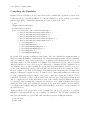
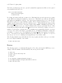
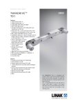
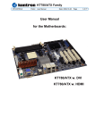
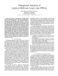
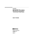
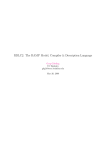
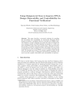
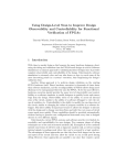
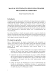
Simulating Verilog RTL using Synopsys VCS
6.375 Tutorial 1
February 1, 2007
In this tutorial you will gain experience using Synopsys VCS to compile cycle-accurate executable
simulators from Verilog RTL. You will also learn how to use the Synopsys Waveform viewer to
trace the various signals in your design. Figure 1 illustrates the basic VCS and SMIPS assembler
toolflow. VCS takes a set of Verilog files as input and produces a simulator. When we execute the
simulator we need some way to observe our design so that we can measure its performance and
verify that it is working correctly. There are two primary ways to observe our design: (1) we can
use $display statements in our Verilog RTL to output textual trace information, or (2) we can
instruct the simulator to automatically write transition information about each signal in our design
to a file. There is standard text format for this type of signal transition trace information called
the Value Change Dump format (VCD). Unfortunately, these textual trace files can become very
large very quickly, so Synopsys uses a proprietary compressed binary trace format called VCD Plus
(VPD). We can view VPD files using the Synopsys waveform viewer called VirSim.
We will be using a simple unpipelined SMIPSv1 processor as our design example for this tutorial,
and thus you will also learn the how to build and run test codes on the processor simulator. Figure 2
shows the block diagram for the example processor. Figure 1 shows the SMIPS assembler toolflow
which starts with an SMIPS assembly file and uses several tools to generate a Verilog Memory Hex
(VMH) file suitable to run on the cycle-accurate simulator. This tutorial assumes you are familiar
with the SMIPS ISA. For more information please consult the SMIPS Processor Specification.
For more information consult the CVS user manual (cvs-user-guide.pdf) located in the course
locker (/mit/6.375/doc).
Getting started
Before using the 6.375 toolflow you must add the course locker and run the course setup script with
the following two commands.
% add 6.375
% source /mit/6.375/setup.csh
2
6.375 Tutorial 1, Spring 2006
ASM
Source
Code
smips−testbuild
SMIPS
Binary
smips−objdump
Verilog
Source
Verilog
Libs
Obj
Dump
VCS
objdump2vmh.pl
Cycle
Accurate
Sim
VMH
Execute Sim
VPD
Trace
Text
Output
VirSim
Figure 1: VCS and SMIPS Assembler Toolflow
3
6.375 Tutorial 1, Spring 2006
For this tutorial we will be using an unpipelined SMIPSv1 processor as our example RTL design.
You should create a working directory and checkout the SMIPSv1 example project from the course
CVS repository using the following commands.
%
%
%
%
mkdir tut1
cd tut1
cvs checkout examples/smipsv1-1stage-v
cd examples/smipsv1-1stage-v
Before starting, take a look at the subdirectories in the smips1-1stage-v project directory. All of
our projects will have a similar structure. Source RTL should be placed in the src directory and test
input files should be placed in the tests directory. The build directory will contain all generated
content including simulators, synthesized gate-level Verilog, and final layout. In this course we
will always try to keep generated content separate from our source RTL. This keeps our project
directories well organized, and helps prevent us from unintentionally modifying our source RTL.
There are subdirectories in the build directory for each major step in the 6.375 toolflow. These
subdirectories will contain scripts and configuration files necessary for running the tools required
for that step in the toolflow. For example, the build/vcs-sim-rtl directory contains a makefile
which can build Verilog simulators and run tests on these simulators. You should browse the source
code for the processor in src to become familiar with the design. The example code makes use
of the simple Verilog component library (VCLIB) located in /mit/6.375/install/vclib. VCLIB
includes a variety of muxes, flip-flops, latches, RAMs, memories, and queues. You are welcome to
either use VCLIB in your own projects or to create your own component library.
eq?
PC
pc+4
ir[20:16]
+4
branch
Instruction Mem
ir[25:21]
rd0
Reg
File
rd1
ir[15:0]
Sign
Extend
>> 2
Control
Signals
Data
Mem
rw
val
addr rdata
wdata
Decoder
rf_wen
Reg
File
Add
val
ir[20:16]
wb_sel
pc_sel
Cmp
tohost_en
tohost
testrig_tohost
Figure 2: Block diagram for Unpipelined SMIPSv1 Processor
6.375 Tutorial 1, Spring 2006
4
Compiling the Simulator
In this section we will first see how to run VCS from the command line, and then we will see how
to automate the process using a makefile. To build the simulator we need to run the vcs compiler
with the appropriate command line arguments and a list of input verilog files.
% pwd
examples/smipsv1-1stage-v
% cd build/vcs-sim-rtl
% vcs -PP +lint=all +v2k -timescale=1ns/10ps \
-v /mit/6.375/install/vclib/vcDecoders.v \
-v /mit/6.375/install/vclib/vcMuxes.v \
-v /mit/6.375/install/vclib/vcArith.v \
-v /mit/6.375/install/vclib/vcStateElements.v \
-v /mit/6.375/install/vclib/vcMemories.v \
../../src/smipsInst.v \
../../src/smipsProcCtrl.v \
../../src/smipsProcDpathRegfile.v \
../../src/smipsProcDpath_pstr.v \
../../src/smipsProc.v \
../../src/smipsTestHarness.v
By default, VCS generates a simulator named simv. The -PP command line argument turns on
support for using the VPD trace output format. The +lint=all argument turns on Verilog warnings.
Since it is relatively easy to write legal Verilog code which is probably functionally incorrect, you
will always want to use this argument. For example, VCS will warn you if you connect nets with
different bitwidths or forget to wire up a port. Always try to eliminate all VCS compilation errors
and warnings. Since we will be making use of various Verilog-2001 language features, we need to
set the +v2k command line option so that VCS will correctly handle these new constructs. Verilog
allows a designer to specify how the abstract delay units in their design map into real time units
using the ‘timescale compiler directive. To make it easy to change this parameter we will specify
it on the command line instead of in the Verilog source. After these arguments we list the Verilog
source files. We use the -v flag to indicate which Verilog files are part of a library (and thus should
only be compiled if needed) and which files are part of the actual design (and thus should always
be compiled). After running this command, you should see text output indicating that VCS is
parsing the Verilog files and compiling the modules. Notice that VCS actually generates ANSI C
code which is then compiled using gcc. When VCS is finished you should see a simv executable in
the build directory.
Typing in all the Verilog source files on the command line can be very tedious, so we will use
makefiles to help automate the process of building our simulators. The following commands will
first delete the simulator you previously built, and then regenerate it using the makefile.
% rm -rf simv
% make simv
6.375 Tutorial 1, Spring 2006
5
The make program uses the Makefile located in the current working directory to generate the file
given on the command line. Take a look at the Makefile located in build/vcs-sim-rtl. Makefiles
are made up of variable assignments and a list of rules in the following form.
target : dependency1 dependency2 ... dependencyN
command1
command2
...
commandN
Each rule has three parts: a target, a list of dependencies, and a list of commands. When a desired
target file is “out of date” or does not exist, then the make program will run the list of commands
to generate the target file. To determine if a file is “out of date”, the make program compares
the modification times of the target file to the modification times of the files in the dependency
list. If any dependency is newer than the target file, make will regenerate the target file. Locate
in the makefile where the Verilog source files are defined. Find the rule which builds simv. More
information about makefiles is online at http://www.gnu.org/software/make/manual.
Not all make targets need to be actual files. For example, the clean target will remove all generated content from the current working directory. So the following commands will first delete the
generated simulator and then rebuild it.
% make clean
% make simv
Building SMIPS Test Assembly Programs
Refer back to Figure 1 to see how the SMIPS assembler fits into the overall toolflow. The
smips-testbuild script calls the SMIPS assembler and linker to compile an assembly file into
an SMIPS binary. Unfortunately, our SMIPS Verilog test harness cannot read SMIPS binaries
directly, so we must use additional tools to convert the SMIPS binary into a usable format. The
smips-objdump program takes the SCALE binary as input and produces a textual listing of the
instructions and data contained in the binary. The objdump2vmh.pl Perl script converts this text
objdump into a Verilog Memory Hex (VMH) file which the Verilog test harness can read into a
magic memory.
We will begin by assembling the smipsv1 example.S assembly test program. Take a look at the
assembly in tests/smipsv1 example.S and notice that this test only has two instructions. We can
use the following commands to generate a VMH file from the assembly file.
% smips-testbuild -smips ../../tests/smipsv1_example.S -o smipsv1_example.S.bin
% smips-objdump --disassemble-all --disassemble-zeroes \
smipsv1_example.S.bin > smipsv1_example.S.dump
% objdump2vmh.pl smipsv1_example.S.dump smimpsv1_example.S.vmh
Compare the original smipsv1 example.S file to the generated smipsv1 example.S.dump. Using
a combination of the assembly file and the objdump file you can get a good feel for what the test
programs are supposed to do and what instructions are supposed to be executed.
6.375 Tutorial 1, Spring 2006
6
We can use the makefile to automate the process of building SMIPS test assembly programs. The
following commands will clean the build directory and then build the desired smipsv1 example.S.vmh
file as well as all required intermediate files.
% rm -rf smipsv1_example.*
% make smipsv1_example.S.vmh
Verify that the corresponding SMIPS binary and objdump file were generated.
The smipsv1 example.S test program was located locally in the tests directory. If you wanted to
add your own test programs, you would add them to this directory. There are additional globally
installed SMIPS assembly test programs located in /mit/6.375/install/smips-tests which you
can use for your lab assignments and projects. The following command will build all of the local
and global assembly tests.
% make asm-tests
Please refer to Tutorial 3: Programming the SMIPS Processor for more information about writing
assembly test programs.
Running the Simulator and Viewing Trace Output
Now that we have learned how to build the simulator and how to build SMIPS test assembly
programs, we will learn how to execute these programs on the simulator. The following command
runs the smipsv1 lw.S test program on the simulator.
% ./simv +exe=smipsv1_lw.S.vmh
You should see some textual trace output showing the state of the processor on each cycle. The
trace output includes the cycle number, reset signal, pc, instruction bits, register file accesses,
testrig tohost signal, and the disassembled instruction. The test program does a series of loads and
verifies that the loaded data is correct. After running all the tests, the program writes a one into
the tohost coprocessor register to indicate that all tests have passed. If any test fails, the program
will write a number greater than one into the tohost register. The test harness waits until the
testrig tohost signal is non-zero and displays either PASSED or FAILED as appropriate.
In addition to the textual output, you should see a vcdplus.vpd in your build directory. Use the
following command to start the Synopsys VirSim waveform viewer and open the generated VPD
file.
% vcs -RPP +vpdfile+vcdplus.vpd
Figure 4 shows the VirSim Hierarchy window. You can use this window to browse the design’s
module hierarchy. Choose Window → Waveform to open a waveform viewer (see Figure 5). To
add signals to the waveform window you can select them in the Hierarchy window and then click
on the Add button in the lower right-hand corner. Alternatively, you can use the middle mouse
button to drag-and-drop signals into the waveform viewer.
7
6.375 Tutorial 1, Spring 2006
Add the following signals to the waveform viewer.
•
•
•
•
•
•
•
•
•
•
•
•
smipsTestHarness.clk
smipsTestHarness.proc.dpath.pc mux sel
smipsTestHarness.proc.dpath.pc
smipsTestHarness.dasm.minidasm
smipsTestHarness.dpath.rf raddr0
smipsTestHarness.dpath.rf rdata0
smipsTestHarness.dpath.rf raddr1
smipsTestHarness.dpath.rf rdata1
smipsTestHarness.dpath.rf wen
smipsTestHarness.dpath.rf waddr
smipsTestHarness.dpath.rf wdata
smipsTestHarness.testrig tohost
The dasm module is a special tracing module which includes Verilog behavioral code to disassemble
instructions. The minidasm signal is a short text string which is useful for identifying which
instruction is executing during each cycle. To display this signal as a string instead of a hex number,
right click on the signal in the waveform viewer. It is important to right click in the proper location;
you must click in the column just to the right of where the signal name is displayed (essentially
you are clicking on what probably looks like 41’hxxxxxxxxxxx). Choose ASCII from the popup
menu. You should now see the instruction type in the waveform window. Use Zoom → Zoom Out
to zoom out so you can see more of the trace at once. Figure 3 shows the waveforms in more
detail. You should be able to identify the addiu instructions correctly loading the register file with
various constants and the lw instructions writing the correct load data into the register file. The
pc mux sel control signal should remain low until the very end of the program when the code starts
into an infinite loop after setting the tohost register to one. After reset, why is the rf rdata1
signal undefined for so many more cycles than rf rdata0?
C1
NA
C2
NA
Delta
NA
V1
Time (1 ns)
50.0
60.0
70.0
80.0
90.0
100.0
110.0
120.0
130.0
140.0
150.0
00001014
00001018
0000101c
00001020
00001024
00001028
clk
V1 pc_mux_sel
V1
pc[31:0] *001000
minidasm[40:0]
V1
?addiu
rf_raddr0[4:0]
V1
00
?lw
00 02
rf_rdata0[31:0]
V1
*000000
rf_raddr1[4:0]
V1
02
00001004
00001090
02 03
00001008
0000100c
?addiu
02 00
?bne
00 04
00000000
03 04
?lw
04
?addiu
04 02
000000ff
03
02 00
00001090
03
000000ff
rf_rdata1[31:0]
V1
V1
00001010
?bne
00 04
00000000
04
?lw
00007f00
04
000000ff
?addiu
04 02
03
02 00
00001090
03
00007f00
?bne
00000000
04
?lw
00 04
04 02
00000ff0
04
03
00007f00
02
00001090
03
00000ff0
rf_wen
V1
rf_waddr[4:0] 02
02 03
rf_wdata[31:0]
V1
*001090
testrig_tohost[7:0]
V1
000000ff
03 04
000000ff
04
03
03
00007f00
04
00007f00
04
03
03
00000ff0
04
00000ff0
04
03
03
0000700f
00
Figure 3: Waveforms for unpipelined SMIPSv1 processor executing smipsv1 lw.S
00
8
6.375 Tutorial 1, Spring 2006
Figure 4: VirSim Module Hierarchy Window
Figure 5: VirSim Waveform Window
6.375 Tutorial 1, Spring 2006
9
The Verilog test harness provides two optional command line arguments in addition to the required
+exe argument as shown below:
simv +exe=<vmh-filename>
+max-cycles=<integer>
+verbose=<0|1>
By default, the harness will run for 2,000 cycles. This limit helps prevent bugs in test programs
or the RTL from causing the simulator to run forever. When there is a timeout, the harness
will display *** FAILED *** timeout. The +max-cycles argument allows you to increase this
limit and is required for longer running programs. If the +verify argument is set to one (the
default), then the harness will execute in “verification mode”. This means that the harness waits
until testrig tohost is non-zero and then outputs either PASSED or FAILED as appropriate. If
the +verify argument is set to zero, then the harness will execute in “performance mode”. This
means that the harness waits until testrig tohost is non-zero and then it outputs a collection of
statistics. You should use “verification mode” for running test programs which verify the correctness
of your processor, and you should use “performance mode” for running benchmarks to evaluate the
performance of your processor. Try running the the smipsv1 addiu.S program in “performance
mode”. You should observe that the Instructions per Cycle (IPC) is one. This is to be expected
since the processor we are evaluating is an unpipelined processor with no stalls.
The following makefile target will build all of the test programs, run them on the processor simulator, and output a summary of the results.
% make run-asm-tests
Review
The following sequence of commands will setup the 6.375 toolflow, checkout the SMIPSv1 processor
example, build the simulator, run all assembly tests, and report the results.
%
%
%
%
%
%
%
add 6.375
source /mit/6.375/setup.csh
mkdir tut1
cd tut1
cvs checkout examples/smipsv1-1stage-v
cd examples/smipsv1-1stage-v/build/vcs-sim-rtl
make run-asm-tests