1
Electrical connections
9.2
23
Pulse output
The VPFlowScope probe features a low-frequency active pulse output. The pulse is a ‘non potential’
free output as it acts like a controlled current output. To make it passive, an external isolator can be
used.
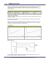
The pulse interval can be set with the VPStudio software. A pulse from 0..20 mA will be generated
when the interval exceeds. The maximum pulse frequency is once per 2 seconds. If the pulse interval
is set to small, a continuous pulse (20mA high level) will be the result.
The pulse output is connected to the internal totalizer value. When the totalizer has increased by the
pulse interval, the pulse will be generated. As it is not possible to generate a negative pulse, negative
flow can not be indicated by pulse. In case of negative flow, the internal totalizer will count
backwards. Pulses will not be generated until the same amount of positive flow has been added to
the totalizer again. In this way we ensure that the pulse output will always be synchronized with the
internal totalizer of the VPFlowScope probe. In case of continuous negative flow, consider to swap
the flow meter direction.
Default settings
Diameter
Diameter
Pulse interval
> 40 mm and < 92 mm
> 1.57 inch and < 3.62 inch
1 m3n
> 92 mm and < 160 mm
> 3.62 inch and < 6.3 inch
2 m3n
> 160 mm and < 205 mm
> 6.3 inch and < 8.07 inch
5 m3n
Pulse output
Electrical scheme:
© 2013 Van Putten Instruments BV | MAN-VP-SPROBE-UK | Revision:1 | Date:29-11-2013