1
Installing the Adapter
2-5
PowerFlex 400 Frames D, E, and F
1. Remove power from the drive.
2. Use static control precautions.
3. Remove the drive cover.
4. With the adapter board right side up, remove its mounting screw
from the lower left hole. Save the screw for mounting in Step 7.
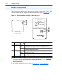
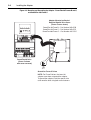
5. Connect the Internal Interface cable to the DSI port on the drive (see
Figure 2.4).
6. With the adapter board oriented bottom side up, route the Internal
Interface cable under the adapter, and then to the mating DSI
connector on the adapter.
7. Install the adapter, bottom side up, to the right side of the display
board by snapping it into place. Then insert the adapter mounting
screw into the lower left hole on the board.
Important: Tighten the mounting screw in the adapter’s lower left
hole to ground the adapter to the drive.
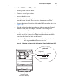
Figure 2.4 Mounting and Connecting the Adapter – PowerFlex 400 Frame D, E,
and F Drives
Adapter Installation
(Side View)
Bottom of
Adapter Board
LEDs
Connector
Internal Interface
Ribbon Cable
PowerFlex 400
(Frame D shown
with cover removed)