1
Model DC100
Communication Interface
Instruction Manual
IM DC100-11E
IM DC100-11E
4th Edition
Introduction
This Communication Interface User’s Manual describes the functions and commands of the optional
GP-IB, RS-232-C, RS-422-A/RS-485, and Ethernet interfaces. Read this manual carefully before
using these interface functions, and be sure to keep this manual on hand for future reference should
any problems arise.
As a manual relative to the DC100, the following manual is also provided. Read it if necessary.
Name of manual
Manual No.
DC100 Data Collector User’s Manual
IM DC100-01E
Note
• YOKOGAWA reserves the right to change the content of this manual at any time without prior
notice because of improvements in performance or functions. Actual displays on the screen may
also be a little different from the screen displays described in this manual.
• All reasonable efforts have been made to ensure the accuracy of this manual. If, however, any
errors or ambiguities are found, please inform YOKOGAWA.
• No part of this manual may be reproduced in any form without the prior written permission of
YOKOGAWA.
• The warranty card is attached to the packing box. This card cannot be reissued. Thoroughly read
the card and carefully store it.
Trademark
• MS-DOS, Windows95 and Visual C are registered trademarks of Microsoft Corporation, USA.
• Other product names are trademarks or registered trademarks of the relevant companies.
History
First edition:
2nd edition:
3rd edition:
4th edition:
July 1997
January 1998
November 1998
November 1999
Disk No. RE11
4th Edition: November 1999 (YK)
All Rights Reserved, Copyright 1997 Yokogawa Electric Corporation
IM DC100-11E
1
Configuration and Use of This Manual
Configuration
This user’s manual is composed of chapter 1 to chapter 8, an appendix and indices.
Chapter 1 Overview and Specifications of GP-IB Interface
Describes the functions and specifications of the GP-IB interface and the address setting
method.
Chapter 2 Overview and Specifications of RS-232-C Interface
Describes the functions and specifications of the RS-232-C interface and the parameter
setting method.
Chapter 3 Overview and Specifications of RS-422A/RS-485 Interface
Describes the functions and specifications of the RS-422-A/RS-485 interface and the
parameter setting method.
Chapter 4 Overview and Specifications of Ethernet Interface
Describes the functions and specifications of the Ethernet interface and the parameter
setting method.
Chapter 5 Command Format
Describes how to specify command formats and channel numbers.
Chapter 6 Commands
Describes the commands for various setting items, commands for executing actions,
data request commands for measured data saved in memory, or commands requesting
output of internally set data.
Chapter 7 Output Format
Describes the output formats for set data, measured data, etc.
Chapter 8 Sample Program
Useful sample programs are presented.
Appendix Computation Equation
Describes the optional computation equation.
Index
There are command and general indices.
This user’s manual does not describe in detail connections and functions for the DC100 systems.
For details on these, see the following separate manual:
“DC100 Data Collector User’s Manual”
IM DC100-01E
2
IM DC100-11E
TABLE OF CONTENTS
1
INTRODUCTION .................................................................................................................................................................... 1
CONFIGURATION AND USE OF THIS MANUAL .................................................................................................... 2
2
CHAPTER 1 OVERVIEW AND SPECIFICATIONS OF GP-IB INTERFACE
1.1
1.2
1.3
Description of Functions (GP-IB) .................................................................................................................. 1-1
Setting of Address of GP-IB Interface ............................................................................................................ 1-3
Specifications .................................................................................................................................................. 1-4
3
CHAPTER 2 OVERVIEW AND SPECIFICATIONS OF RS-232-C INTERFACE
2.1
2.2
2.3
2.4
2.5
2.6
Description of Functions (RS-232-C) ............................................................................................................. 2-1
Specifications .................................................................................................................................................. 2-3
RS-232-C Interface Connection ..................................................................................................................... 2-4
Handshake Format Selection .......................................................................................................................... 2-6
Communication Data Format ......................................................................................................................... 2-8
RS-232-C Interface Parameter Setting Procedure .......................................................................................... 2-9
4
5
CHAPTER 3 OVERVIEW AND SPECIFICATIONS OF RS-422-A/RS-485 INTERFACE
3.1
3.2
3.3
3.4
3.5
Description of Functions (RS-422-A/RS-485) ............................................................................................... 3-1
Specifications .................................................................................................................................................. 3-2
RS-422-A/RS-485 Interface Connection ........................................................................................................ 3-3
Communication Data Format ......................................................................................................................... 3-8
RS-422-A/RS-485 Interface Parameter Setting Procedure ............................................................................. 3-9
6
7
CHAPTER 4 OVERVIEW AND SPECIFICATIONS OF ETHEMET INTERFACE
4.1
4.2
4.3
4.4
4.5
4.6
4.7
4.8
4.9
Introduction of Functions (Ethernet) .............................................................................................................. 4-1
Specifications .................................................................................................................................................. 4-3
Names and Functions of Each Section. .......................................................................................................... 4-4
Setting the IP Address .................................................................................................................................... 4-6
Connection Methods ....................................................................................................................................... 4-8
Checking the Connection (Loopback test) ..................................................................................................... 4-9
Transfrring the instantaneous Values ........................................................................................................... 4-10
Dispiaying the Communication Information ................................................................................................ 4-12
Setting the Timeout ....................................................................................................................................... 4-14
Command Format ........................................................................................................................................... 5-1
Command Syntax ............................................................................................................................................ 5-3
Setting a Channel No., and Alarm Output Relay No. ..................................................................................... 5-4
Command List ................................................................................................................................................ 5-5
Input Range Parameter ................................................................................................................................... 5-7
ASCII Code Table ........................................................................................................................................ 5-11
Default Status ................................................................................................................................................ 5-12
CHAPTER 6 COMMANDS
6.1
IM DC100-11E
App
Index
CHAPTER 5 COMMAND FORMAT
5.1
5.2
5.3
5.4
5.5
5.6
5.7
8
Setting the Input .............................................................................................................................................. 6-1
Range Setting (SR)
Unit Setting (SN)
Filter Setting (XQ)
Measurement Period Setting (XV)
A/D Integration Setting (XI)
3
TABLE OF CONTENTS
6.2
6.3
6.4
6.5
6.6
4
Setting Alarms ................................................................................................................................................ 6-4
Alarm Setting (SA)
Performs Alarm-related Settings (XA)
Relay Reflash Setting (XY)
Relay AND/OR Setting (XN)
Relay Energizing/Deenergizing Setting (XD)
Relay Hold/Non-hold Setting (XH)
Setting the Display .......................................................................................................................................... 6-5
Setting the display mode on the upper part of the display (UD)
Setting the display mode on the middle part of the display (MD)
Setting the display mode on the lower part of the display (LD)
Setting the switching time for the displayed channel (XW)
Settings Relating to the Way Data Are Saved ................................................................................................ 6-7
Setting channels through which measured/computed data are written (MH)
Setting the method for writing measured/computed data (MW)
Setting items relating to the RAM disk (XW)
Other Settings ................................................................................................................................................. 6-8
Date and time setting (SD)
Moving average setting (SV)
Message setting (SG)
Tag setting (ST)
Copy between channels (SY)
Group setting (SX : with optional computation function)
Timer setting (SI)
Match time setting (SQ)
Event/action setting (SL)
Computation Expression Setting (SO : with optional computation function)
Computation Constant Setting (SK : with optional computation function)
Communication Input Data Setting (CM : with optional computation function)
Setting Data (Periodic File/Report File) to Save (MX: with optional report computation function)
Setting hourly/daily/monthly report to ON/OFF and the time to create the report (RO : with optional report
function)
Setting report channel to ON/OFF and the report computation type (RM : with optional report function)
Summer/winter time (SW)
Channel number or tag selection (XR)
Key lock setting (XK)
Function screen setting (XF)
Setting screen setting (XS)
Burnout setting (XB)
Reference junction compensation setting (XJ)
Setting SCSI ID Number (YI: with optional SCSI)
Setting of Computation Error Handling Method (XG : with optional computation function)
Setting of temperature unit (XT)
Setting of language (XL)
Setup setting data (XE)
Specifies the file to transfer (_M0)
Add a SUM value to the binary data (CS)
Setting for execution, data modification, and data storage in A/D calibration (XZ)
Control and Execution Command ................................................................................................................ 6-16
Acknowledgment of alarm status (AK)
Alarm reset (AR)
Timer reset (IR)
Computation start/stop (EX : with optional computation function)
Starting/stopping the writing of measured/computed data (WS)
Copying a file of measured/computed data (WC)
Writing one scan’s worth of measured/computed data (DW)
Deleting files on a RAM disk (ME)
Copying a file after converting data to ASCII format (MY)
IM DC100-11E
TABLE OF CONTENTS
6.7
Storing set data on a floppy disk (FV)
Reading setting data on a floppy disk (FL)
Deleting a file on a floppy disk (FE)
Storing set data in setup mode (YV)
Reading set data, which have been stored, in setup mode (YL)
Deleting a file in setup mode (YE)
Executes the initial balancing of the strain input channel (BL)
Report start/stop (DR : with optional report function)
System reconstruction (RS)
RAM clear (RC)
Setting mode selection (DS)
Clearing Built-in RAM Disk (MI)
Data Output Request Command ................................................................................................................... 6-19
Selection of talker output data (TS)
Measured data output request (FM)
Format specification for measured data on the RAM disk (MF)
Report data output request (RF : with optional report function)
Setting data output request (LF)
System configuration data output request (CF)
The file specifies by _M0 output request (_M1)
Byte output order specification (BO)
Interrupt mask specification (IM)
Auxiliary mask specification (SM)
1
2
3
4
5
6
CHAPTER 7 OUTPUT FORMAT
7.1
7.2
7.3
7.4
7.5
7.6
7.7
7.8
7.9
7.10
7.11
7.12
7.13
Functions as Talker ......................................................................................................................................... 7-1
Measured/Computed Data Output Format (ASCII code) ............................................................................... 7-2
Measured/Computed Data Output Format (Binary code) .............................................................................. 7-3
Setting Data Output Format (Operation mode) .............................................................................................. 7-4
Setting Data Output Format (Setup mode) ..................................................................................................... 7-6
Output Format for Unit and Decimal Point Position ...................................................................................... 7-7
System Configuration Output Format ............................................................................................................ 7-8
A/D Calibration Data Output Format ............................................................................................................. 7-9
RAM Disk Output Format (File Directory Output) ...................................................................................... 7-10
RAM Disk Output Format (ASCII Code) .................................................................................................... 7-11
RAM Disk Output Format (Binary Code) .................................................................................................... 7-13
RAM Disk Output Format (Channel On/Off) .............................................................................................. 7-15
Report Output Format (planned for future release) ...................................................................................... 7-16
CHAPTER 8 SAMPLE PROGRAM
8.1
8.2
8.3
8.4
GP-IB Sample Programs ................................................................................................................................. 8-1
RS-232-C Sample Programs ........................................................................................................................... 8-4
RS-422-A/RS-485 Sample Programs ............................................................................................................. 8-7
Ethernet Sample Progeams ........................................................................................................................... 8-13
APPENDIX
App. 1
Computing Equation ....................................................................................................................... App-1
INDEX
General index .................................................................................................................................................... Index-1
Command Index ................................................................................................................................................ Index-4
IM DC100-11E
5
7
8
App
Index
1.1
Description of Functions (GP-IB)
1
Listener Function
This allows almost all settings except power on/off and operation control.
• Settings except communication settings.
• Operation control except power on/off.
• Call-up of setting data
• Specifying of output data (specifying of channel numbers or output data types)
• Specifying of causes of interrupt generation (see IM command: page 6-20)
Talker Function
The following data can be output:
• Measured data
• Data on RAM disk
• Report data
• Computed data
• System configuration
• Data for operation mode setting
• Data for setup mode setting
For measured data, data on RAM disk and computed data, either binary output or ASCII output can
be selected. Report data are output in binary format. Other data are output in the form of ASCII
data.
Data Output
When trigger (GET) becomes activated, DC100 will store the new data in a buffer. When an output
request such as the FM command is received, these new data will be output.
Note when dividing and reading in data output from DC100 with the personal computer:
The data group being read in after ATN* has just become TRUE may miss its first bite.
Example of N88-BASIC (Standard language for PC9801 series)
Dividing and reading in measured data by every line
70 PRINT @1; “FM0, 001,010”
80 LINE INPUT @1; D$: PRINT D$
90 LINE INPUT@1; D$: PRINT D$
100 IF MID$ (D$, 2, 1)<>“E” THEN 90
Because the specification of talker address is repeated in the line 90 LINE INPUT@1; D$:PRINT
D$, ATN becomes TRUE before the third data group being read in.
Precaution:
70 PRINT @1; “FM0, 001,010”
80 LINE INPUT @1; D$: PRINT D$
90 LINE INPUT@; D$:PRINT D$
100 IF MID$ (D$,2,1)<>“E” THEN 90
The command is changed into LINE INPUT@; D$:PRINT D$ in the line 90.
ATN won’t become TRUE if the specification of talker address is not repeated.
It’s unnecessary to repeat the specification when reading in data from the same address.
* ATN is a signal for data distinction:
TRUE (0) Device message
FALSE (1) Interface message
IM DC100-11E
1-1
Overview and Specifications of GP-IB Interface
Listener and Talker Functions
1.1 Description of Functions
Status Byte Format
The format of status byte output in serial polling is as follows:
Upper-level byte
Lower-level byte
0
Interrupt generated at the end of A/D conversion.
Interrupt generated at the time of syntax error.
Interrupt generated when the internal timer is being operated
or hourly, daily and monthly reports are created.
Interrupt generated after storing data on media.
Interrupt generated when a file alarm occurs.
Interrupt generated when measurement release is generated
while computation is in progress (with computation
functions).
SRQ
Bit 8:
Bit 7:
Not used. Always 0.
SRQ
This bit changes to 1 when any cause of the bits 1 to 6 has been generated and interrupts the
controller. After responding to serial polling, this bit is set to 0.
Bit 6 This bit changes to 1 when a measurement release is generated while the computation is in
progress; otherwise, it is 0. This bit is effective only with optional computation functions.
After responding to serial polling, this bit is set to 0.
Bit 5 This bit changes to 1 when a file alarm occurs. After responding to serial polling, this bit is
set to 0.
Bit 4 This bit changes to 1 after storing data on media ; otherwise, it is 0. After responding to
serial polling, this bit is set to 0.
Bit 3 This bit changes to 1 when the internal timer is being operated or hourly, daily and monthly
reports are created. Whenever one of the internal timers 1 to 6 is being used or reports are
created, the bit changes to 1. After serial polling has been performed, this bit will be reset to
0.
Bit 2: This bit changes to 1 when a syntax error occurs in a command and is normally 0.
If there is an error in a command description, this changes to 1. After responding to serial
polling, this bit is set to 0.
Bit 1: This bit changes to 1 at the end of an A/D conversion; otherwise, it is 0.
When the A/D conversion of measured data is terminated, this changes to 1. After responding
to serial polling, this bit is set to 0.
Status byte and serial polling
• In IM commands, the bit status that is to be made effective must be specified. The status of
unspecified bits does not change to 1.
• If a new cause is generated before reading out a status byte for which a cause has already been
generated, the existing cause remains in the status byte as is and the new cause is added. For
example, if bit 1 is in 1 state and bit 2 is newly changed to 1 before reading out the status byte,
both bit 1 and bit 2 become 1.
The initial value
The initial value is ‘ IM2 ’.
1-2
IM DC100-11E
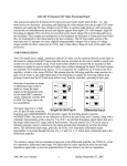
1.2
Setting of Address of GP-IB Interface
1
CDE
AB
4 56
789
789
Rotary switch with
which address is
to be set
IM DC100-11E
4 56
23
CDE
AB
23
F0 1
F0 1
Address is the numeral
to which the arrow is pointed
1-3
Overview and Specifications of GP-IB Interface
The GP-IB address is set with the rotary switch located on the side of the GP-IB module connector.
Turn the arrow on the rotary switch with a flat-blade screwdriver or the like to align the arrow with
the address to be set.
1.3
Specifications
Electrical and mechanical specifications: Conforming to IEEE St’d 488-1975
Code to be used:
ISO (ASCII) code
Function specifications
1-4
Function
Subset name
Description
Source handshake
Acceptor handshake
Talker
SH1
AH1
T6
Listener
L4
Service request
Remote/local
Parallel poll
Device clear
Device trigger
Controller
SR1
RL1
PP0
DC1
DT1
C0
All transmission handshake functions operative
All transmission handshake functions operative
Basic talker functions, serial poll, and talker release function
by listener are provided.
Basic listener function and listener release function by talker
are provided.
All service request functions operative
All remote/local functions operative
No parallel poll function
All device clear functions operative
All device trigger functions operative
No controller function
IM DC100-11E
2.1
Description of Functions (RS-232-C)
Listener and Talker Functions
Data Output
When trigger (GET) becomes activated, DC100 will store the new data in a buffer. When an output
request such as the FM command is received, these new data will be output.
IM DC100-11E
2-1
2
Overview and Specifications of RS-232-C Interface
Listener Function
This allows almost all settings except power on/off and operation control.
• Settings except communication settings.
• Operation control except power on/off.
• Call-up of setting data
• Specifying of output data (specifying of channel numbers or output data types)
Talker Function
The following data can be output:
• Measured data
• Data on RAM disk
• Report data
• Computed data
• System configuration
• Data for operation mode setting
• Data for setup mode setting
For measured data, data on RAM disk and computed data, either binary output or ASCII output can
be selected. Report data are output in binary format. Other data are output in the form of ASCII
data.
2.1 Description of Functions
Commands Applicable to RS-232-C Only
The following commands are only applicable to RS-232-C.
ESC T
Trigger Execution
Setting
ESC T<terminator>
Description
Before executing this command, select the output data using the TS command. The
data selected with the TS command are prepared for output. The data are output
with the FM, LF, CF, MF or RF command.
ESC S
Status Output Command
Setting
ESC S<terminator>
Description
The status for a sent command is output.
ESC R Switch from Local Status to Remote Status
Setting
ESC R<terminator>
Description
• Panel setting conditions in the local status are retained even if the status is switched
to the remote status.
• When the status is switched to the remote status, no key except DISP can be used.
Panel operation can be done by pressing the DISP key or switching the status to
local using the ESC L command described below.
ESC L
Switch from Remote Status to Local Status
Setting
ESC L<terminator>
Description
The panel setting conditions in the remote status are retained even if the status is
switched to the local status.
Note
• ESC corresponds to hexadecimal code (1B)H.
Status Byte Format
When the status byte ousÙµt command (ESC S) is received, any of the ER00CRLF to ER03CRLF
status will be output.
ER
CrLf
An ASCII character string of a numeral (numerals) shown
in parentheses at the end of any of the following items or
the sum of the numerals of the relevant items is output.
For example, if a file alarm and timer operation occur,
ER20CrLf is output.
Items not specified with an IM command are invalid and
not included in this status output.
• A/D conversion end (1)
When an A/D conversion for measured data ends, “1” is output.
• Syntax error (2)
If an error occurs in the description of a command, “2” is output.
• Internal timer or time when hourly, daily and monthly reports are created(4)
If any of the 6 timers (1 to 6) or the time for hourly, daily and monthly reports arrives set with
an auxiliary mask operates, “4” is output.
• Storing data end (8)
When storing data on media ends, “8” is output.
• File alarm (16)
If a file alarm is detected, “16” is output.
• Measurement release (32)
If a measurement release is generated while the computation is in progress, “32” is output.
Items Applicable to RS-232-C Only
With RS-232-C, all commands can be acknowledged by ACK output. The ACK output is as follows,
except for the FM, LF, CF, RF, MF, BL and _M commands, whose ACK output will described later
on.
E0
: Commands are processed succesfully
E1
: Commands are not processed succesfully
After having sent the output request, make sure to retrieve the data.
2-2
IM DC100-11E
2.2
Electrical & mechanical specs
Connection format
Communication format
Synchronizing format
:
:
:
:
Baud rate (bps)
:
START bit
Data length
Parity
STOP bit
Connector
Hardware handshake
Software handshake
Reception buffer length
Escape sequence
:
:
:
:
:
:
:
:
:
Conform to the EIA RS-232-C Standard.
Point-to point
Half duplex
Start-stop asynchronous transmission
(synchronized by start/stop bit)
150, 300, 600, 1200, 2400, 4800, 9600, 19200, or 38400
(selectable)
1 bit, fixed.
Either 7 or 8 bits (selectable).
Even, Odd, or None (selectable).
Either 1 or 2 bits (selectable).
DBSP-JB25S (JAE)
Transmission/reception control by DTR, RTS, CTS.
Transmission control by XON, XOFF.
200 bytes
Trigger;
Status call.
2-3
2
Overview and Specifications of RS-232-C Interface
IM DC100-11E
Specifications
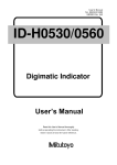
2.3
RS-232-C Interface Connection
When connecting this instrument to a personal computer, first it is necessary to match settings such
as handshake format, data transmission speed, and data format at the computer’s side. For details
relating to these settings, refer to the description on this and following pages. Furthermore, make
sure to use an interface cable which matches this instrument’s specifications.
Connector and Signal Names
2
3
4
5
20
7
Numeric values in the above figure indicate Pin Nos.
2.TXD (Send Data)
: Data transmitted to the host computer.
Signal direction : Output.
3.RXD (Received Data)
: Data received from the host computer.
Signal direction : Input.
4.RTS (Request to Send)
: Handshake signal used for reception of data from the host computer.
Signal direction : Output.
5.CTS (Clear to Send)
: Handshake signal used for transmission of data to the host
computer.
Signal direction : Input.
7.GND (Signal Ground)
: Signal ground connection.
20.DTR (Equipment Ready) : Handshake signal used for reception of data from the host
computer.
Signal direction : Output.
Pin Nos. 1, 6, 8 to 19 and 21 to 25 are not used.
Signal direction
Host Computer
2-4
DTR [Transmission request
reception OK]
20
RTS [Transmission request
reception OK]
4
CTS [Transmission enable
Ready]
5
TXD [Transmission data]
2
RXD [Reception data]
3
DC100
IM DC100-11E
2.3 RS-232-C Interface Connection
RS-232-C Signal List and Corresponding JIS & CCITT Abbreviation
Signal Table
Abbreviation
Pin No.
CCITT
7
AB(GND)
102
SG
Signal ground
2
BA(TXD)
103
SD
Transmitted data
3
BB(RXD)
104
RD
Received data
5
CB(CTS)
106
CS
Transmission enable
4
CA(RTS)
105
RS
Transmission request
20
CD(DTR)
108/2
ER
Data terminal ready
2
Overview and Specifications of RS-232-C Interface
IM DC100-11E
Name
JIS
RS-232-C
2-5
2.4
Handshake Format Selection
In order to ensure proper data transfers between the instrument and the host computer via the RS232-C interface, a mutual procedure is required for processing the electrical signals. Such a procedure
is referred to as a ‘handshake’. Several handshake formats are available, with selection depending
on the host computer being used. The same handshake format must be designated for both the
instrument and the host computer.
The instrument’s parameter settings permit any one of the following 5 formats to be selected.
Format
Selection
Transmission Data Control
(Control format when transmitting data
to the host computer)
Software
Hardware
Handshake
Handshake
No
Transmission is Transmission
Handshake
stopped when
is stopped
X-OFF is
when CTS is
received, and is FALSE, and is
resumed when
resumed when
X-ON is
CTS is TRUE.
received.
Reception Data Control
(control format when receiving data
from the host computer)
Hardware
Handshake
When reception
of data becomes
impossible DTR
becomes
FALSE, when
data reception
becomes
possible DTR
becomes TRUE.
When reception
of data becomes
impossible RTS
becomes
FALSE, when
data reception
becomes
possible RTS
becomes TRUE.
No
Handshake
OFF-OFF
XON-RTS
XON-DTR
CTS-RTS
CTS-DTR
OFF-OFF
• Transmission data control
• Reception data control
: There is no handshake status between the instrument and host
computer. the X-ON and the X-OFF signal from the host computer
is processed as data, and the CTS signal is ignored.
: There is no handshake status between the instrument and host
computer. When the instrument’s reception buffer becomes full,
the excess data is discarded.
DTR=True, RTS=True (both fixed).
Note
• It is necessary to create a host computer program which prevents the instrument and host computer’s reception buffers
from becoming full.
XON-RTS
• Transmission data control
• Reception data control
2-6
: A software handshake status is established between the instrument
and the host computer. The instrument will stop a data transmission
when an X-OFF signal is received from the host computer. The
transmission will be resumed when the next X-ON signal is
received.
The CTS signal from the host computer is ignored.
: A hardware handshake status is established between the instrument
and the host computer. When the instrument’s reception of data
becomes impossible, an ‘RTS=False’ status will be established.
When data reception becomes possible, an ‘RTS=True’ status will
be established. DTR=True (Fixed).
IM DC100-11E
2.4 Handshake Format Selection
XON-DTR
• Transmission data control
• Reception data control
• Reception data control
CTS-DTR
• Transmission data control
• Reception data control
IM DC100-11E
: A hardware handshake status is established between the instrument
and the host computer. The instrument will stop a data transmission
if a ‘CTS=False’ status is established, and will resume the
transmission when a ‘CTS=True’ status is established. The XOFF and X-ON signals from the host computer are processed as
data.
: A hardware handshake status is established between the instrument
and the host computer. An ‘RTS=False’ status will be established
when the instrument’s reception of data becomes impossible, and
an ‘RTS=Ture’ status will be established when data reception
becomes possible. DTR=Ture (Fixed).
: A hardware handshake status is established between the instrument
and the host computer. The instrument will stop a data transmission
if a ‘CTS=False’ status is established, and will resume the
transmission when a ‘CTS=True’ status is established. The XOFF and X-ON signals from the host computer are processed as
data.
: A hardware handshake status is established between the instrument
and the host computer. A ‘DTR=False’ status will be established
when the instrument’s reception of data becomes impossible and
a ‘DTR=True’ status will be established when data reception
becomes possible. RTS=Ture (Fixed).
2-7
2
Overview and Specifications of RS-232-C Interface
CTS-RTS
• Transmission data control
: A software handshake status is established between the instrument
and the host computer. The instrument will stop a data transmission
when an X-OFF signal is received from the host computer. The
data transmission will be resumed when the next X-ON signal is
received. The CTS signal from the host computer is ignored.
: A hardware handshake status is established between the instrument
and the host computer. When the instrument’s reception of data
becomes impossible, an ‘DTR=False’ status will be established.
When data reception become possible, an ‘DTR=True’ status will
be established.
RTS=True (Fixed).
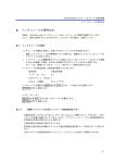
2.5
Communication Data Format
The RS-232-C interface uses a START-STOP communication format. With this format, a START
bit is placed at the beginning of each character transmitted, followed by the data bits, parity bit, and
stop bit, in that order. (See the figure below.)
‘Line idle’
condition
Return to ‘line idle’ condition
(dotted line), or proceed to
next data START bit.
1 character
Data bits
(7-8 bits)
STOP bit
START bit
2-8
Parity bit(Odd,
even, or none)
1
1 or 2
2
IM DC100-11E
2.6
RS-232-C Interface Parameter Setting Procedure
Setting of the RS-232-C parameters must be carried out using the 3 dipswitches located next to the
module connector.
1 2
Parameter setting
switch 2
1 2
Parameter setting
switch 3
1 2
3 4
Overview and Specifications of RS-232-C Interface
Parameter setting
switch 1
ON
OFF
Data length
Baud rate
3 4
ON
OFF
Baud rate
Stop bit
Parity
3 4
ON
OFF
Not use
Handshake system
Baud rate ( No.1 to 3 of setting switch 1 and No.4 of setting switch 2)
Baud rate
No.1
No.2
No.3
No.4 (Swith 2)
150
300
600
1200
2400
4800
9600
19200
38400
OFF
OFF
OFF
OFF
ON
ON
ON
ON
OFF
OFF
OFF
ON
ON
OFF
OFF
ON
ON
OFF
OFF
ON
OFF
ON
OFF
ON
OFF
ON
OFF
OFF
OFF
OFF
OFF
OFF
OFF
OFF
OFF
ON
←Default
Data length (Switch No.4 of parameter setting switch 1)
Data length
No.4
7
8
OFF
ON
←Default
Parity (Switch No.1 and 2 of parameter setting switch 2)
Parity
No.1
No.2
NONE
ODD
EVEN
OFF
OFF
ON
OFF
ON
OFF
←Default
Stop bit (Switch No.3 of parameter setting switch 2)
Stop bit
No.4
1
2
OFF
ON
←Default
Handshake system (Switch No.1 to 3 of parameter setting switch 3)
Handshake system
No.1
No.2
No.3
No handshake
OFF
OFF
OFF
←Default
XON-ER*
OFF
OFF
ON
XON-RS*
OFF
ON
OFF
CS-ER
OFF
ON
ON
CS-RS
ON
OFF
OFF
* When the baud rate is set to 38400, there is no handshaking
IM DC100-11E
2
2-9
3.1
Description of Functions (RS-422-A/RS-485)
Listener and Talker Functions
Listener Function
This allows almost all settings except power on/off and operation control.
• Settings except communication settings.
• Operation control except power on/off.
• Call-up of setting data
• Specifying of output data (specifying of channel numbers or output data types)
3
Data Output
When trigger (ESC T) becomes activated, DC100 will store the new data in a buffer. When an
output request such as the FM command is received, these new data will be output.
Commands Applicable to RS-422-A/RS-485 Only
The following commands are only applicable to RS-422-A/RS-485.
ESC O Open Command (address a communication destination)
Setting
ESC O xx<terminator>
xx : address, 01 to 31
Description
Specifies the communicating device by its address. When this command is executed, all commands to the DC100 (including ESC T) become effective.
• Only one device can be opened.
• Executing ESC O automatically closes all opened devices.
• When the DC100 receives this command correctly, it sends “ESC O xx” in
response to the computer.
• CR+LF can only used for the terminator.
ESC C Close Command (close the addressed state of a device)
Setting
ESC C xx<terminator>
xx : address, 01 to 31
Description
Disconnects the device currently connected. When this command is executed, it
allows opening communication with other devices with the ESC O command.
• When the DC100 receives this command correctly, it sends “ESC C xx” in
response to the computer.
• CR+LF can only used for the terminator.
The following commands are same as the RS-232-C interface. For details, refer to page 2-2.
ESC T (Trigger Execution), ESC S (Status Output Command)
Note
• ESC corresponds to hexadecimal code (1B)H. On the N88-BASIC, “ESC x” is denoted as “CHR$(&H1B)+”x”.”
IM DC100-11E
3-1
Overview and Specifications of RS-422-A/RS-485 Interface
Talker Function
The following data can be output:
• Measured data
• Data on RAM disk
• Report data
• System configuration
• Data for operation mode setting
• Data for setup mode setting
For measured data and data on RAM disk, binary output or ASCII output can be selected. (for RS422-A with using the multi point.) Report data are output in binary format. Other data are output in
the form of ASCII data.
3.2
3-2
Specifications
Electrical & mechanical specs
Connection format
Communication format
Synchronizing format
:
:
:
:
Baud rate (bps)
START bit
Data length
Parity
STOP bit
Connector
Minimum response time
Reception buffer length
Escape sequence
Electrical characteristics
:
:
:
:
:
:
:
:
:
:
Communication distance
Terminator
:
:
Conform to the EIA RS-422-A and EIA RS-485 Standard
Multi-drop 1:n (n=16 for RS-422-A, n=31 for RS-485)
Half duplex
Start-stop asynchronous transmission (synchronized by start/stop
bit)
300, 600, 1200, 2400, 4800, 9600, 19200, or 38400 (selectable)
1 bit (fixed)
Either 7 or 8 bits (selectable)
Even, Odd, or None (selectable)
Either 1 or 2 bits (selectable)
6 point screw type terminal (uses M4 screws)
0, 10, 20, 50 or 100 ms (selectable)
250 bytes
Trigger, Status call, Open and Close
SDA, SDB, RDA, RDB, SG. Between the signal terminal and
the main internal circuit is insulated functionally.
1.2 km maximum
Internal resistor (120 ohm, 1W) switch with the slide switch
IM DC100-11E
3.3
RS-422-A/RS-485 Interface Connection
The following explains how the RS-422-A/RS-485 module is connected to the computer.
Cable Used
Terminal Arrangement of the RS-422-A/RS-485 Module
RD A Receive data A ( - )
SD A Send data A ( - )
RD B Receive data B ( + )
SD B Send data B ( + )
FG
SG
Frame ground
Signal ground
Screws used for the terminals:
ISO M4 screws, length 6 mm
Connecting the Cable
Attach crimp-on lugs (for 4 mm screws) with insulation sleeves on the leadwire ends as shown in the
diagram below. Make the exposed portion of the shielded cable to be less than 5 cm.
FG
Short the terminals.
Shield
potential
SG
SD A
SD/RD A
SD/RD B
SD B
SG
RD B
FG
RD A
Shield potential
For four-wire system
For two-wire system
WARNING
To prevent an electric shock, ensure the main power supply is turned OFF.
Note
• As shown on the next page, connect terminal RD to SD(TD) of the computer (converter) and terminal SD to RD of the
computer.
IM DC100-11E
3-3
3
Overview and Specifications of RS-422-A/RS-485 Interface
There are two types of cables: two-wire cable and four-wire cable. Make sure each type meets the
following conditions.
Cable used
: twisted pair shielded cable
2 pairs of 24 AWG minimum (two-wire), 3 pairs 24 AWG minimum (four-wire)
Characteristic impedance
: 100 ohm
Capacitance
: 50 pF/m
Length of cable
: 1.2 km maximum *
* Communication distance of the RS-422-A/RS-485 interface is not the linear distance, but the
total length of the cable (shielded twisted pair cable).
3.3 RS-422-A/RS-485 Interface Connection
Connecting to the Host Computer
Can be connected to a host computer with RS-232-C, RS-422-A, RS-485 ports.
• In the case of RS-232-C, a converter is used as shown in the diagram below.
• For information on recommended converters, refer to “Converters” in the latter.
• Dip switch needs to be changed depending on whether it is a two-wire system or four-wire system. Refer to “3.5 RS-422-A/RS-485 Interface Parameter Setting Procedure.”
In the case of four-wire system
In general, the recorder is wired to the host computer using a four-wire system. When four-wire
system is used, the send and receive wires need to be crossed.
Host
Computer
Terminator (Internal ON)
Terminator (externally applied) 120 ohm, more than 1/2 W
RS-422-A/RS-485
module
of the DC100
SDA( - )
SD A
SD A
(SDA)
(SDA)
SD B
SDB( + )
(SDB)
RDA( - )
(RD A)
RDB( + )
(RD B)
SG
(SG)
SD A
(SDA)
SD B
(SDB)
RD A
SD B
(SDB)
RD A
RD B
RD A
(RD A)
(RD A)
RD B
RD B
(RD B)
(RD B)
SG
SG
SG
(SG)
(SG)
FG
FG
#1
FG
#2
#n
(#n≤31)
No terminators are inserted between #1 through #n-1 (internal OFF)
(Diagram below shows the case when the port of the host computer is RS-232-C)
Host
Computer
Terminator (Internal ON)
Terminator (externally applied) 120 ohm, more than 1/2 W
RS-422-A/RS-485
module
of the DC100
RS-232-C
SD A
TD( - )
(SDA)
TD( + )
(SDB)
RD( - )
SD B
(RD A)
SHIELD
(SG)
RD A
(RD A)
RD B
SG
RD B
(RD B)
(RD B)
SG
SG
(SG)
(SG)
#1
SD B
(SDB)
(RD A)
FG
3-4
SD B
RD A
RD B
(RD B)
SD A
(SDA)
(SDB)
RD A
RD( + )
Converter
Z - 101HE
(SHARP)
SD A
(SDA)
FG
#2
FG
#n
(#n≤31)
No terminators are inserted between #1 through #n-1 (internal OFF)
IM DC100-11E
3.3 RS-422-A/RS-485 Interface Connection
In the case of two-wire system
Connect send and receive terminals with the same signal polarity on the terminal arrangement of the
RS-422-A/RS-485 module. Only two wires are used in connecting to other units.
Host
Computer
Terminator (Internal ON)
Terminator (externally applied) 120 ohm, more than 1/2 W
RS-422-A/RS-485
module
of the DC100
SDA( - )
(B)
RDB( + )
SD B
(B)
RD A
RD A
RD A
RD B
RD B
RD B
SG
SG
(SG)
SG
(SG)
(SG)
FG
FG
#1
3
SD A
(A)
SD B
(B)
RDA( - )
SG
SD A
(A)
SD B
Overview and Specifications of RS-422-A/RS-485 Interface
SDB( + )
SD A
(A)
FG
#2
#n
(#n≤31)
No terminators are inserted between #1 through #n-1 (internal OFF)
(Diagram below shows the case when the port of the host computer is RS-232-C)
Host
Computer
Terminator (Internal ON)
Terminator (externally applied) 120 ohm, more than 1/2 W
RS-422-A/RS-485
module
of the DC100
RS-232-C
SD A
TD( - )
(A)
TD( + )
(B)
SD B
RD( + )
SD B
SD B
(B)
RD A
RD A
RD A
RD B
RD B
RD B
SG
(SG)
SG
FG
FG
#1
SG
(SG)
(SG)
Converter
Z - 101HE
(SHARP)
SD A
(A)
(B)
RD( - )
SHIELD
SD A
(A)
#2
FG
#n
(#n≤31)
No terminators are inserted between #1 through #n-1 (internal OFF)
Note
• The method in eliminating noise depends on the condition in which it is used. In the example, shielded cable is grounded
only at the DC100 (one-sided grounding). This method is effective in eliminating noise in long distance communication in
which there is potential difference between the ground of the PC and the ground of the DC100. When there is no potential
difference between the ground of the PC and the ground of the DC100, grounding both sides (two-sided grounding) is
sometimes effective. In addition, there are cases when grounding both sides with one side having a capacitor connected in
series is effective.
Consider all the above cases in eliminating the noise.
IM DC100-11E
3-5
3.3 RS-422-A/RS-485 Interface Connection
Converter
Recommended converter
: Sharp Z-101HE
CAUTION
Some converters other than the recommended, do not have the FG and SG terminals insulated. In such cases, do not connect as in the diagram on the previous
page (do not connect anything to the FG and SG terminals of the converter). Especially when it is long distance, the potential difference may damage the devices
or the communication may become unreliable.
Also, converters without the SG terminal can be used without grounding. For
details, refer to the converter’s manual.
Some converters other than the recommended have their signal polarity reversed (indication of A/B
or +/-). In this case, reverse the connection. If the “RD” LED on the front panel of the RS-422-A/
RS-485 module blinks when it receives data, the connection is correct. If it lights, the connection
may be reversed.
In the case of the two-wire system, the host computer must control the ON/OFF of the transmission
driver of the converter in order to prevent the collision of the send and receive data. When using the
recommended converter, ON/OFF is controlled using RTS.
Using the Module with Devices Using the RS-422-A
Maximum of 31 devices with respect to 1 host computer can be connected with this module, but in
a system in which devices using the RS-422-A are used together, this may not be possible.
• In a system in which former Yokogawa recorders are used together
Some of the former Yokogawa recorders (such as HR2400 and µR) use the RS-422-A driver. In
this case, the maximum number of devices that can be connected is 16.
Note
• According to the RS-422-A standard, the maximum number of devices that can be connected with respect to one port is 10
devices (in the case of a four-wire system).
Terminator
When devices are connected in multi-drop configuration (includes point-to-point connections), turn
the terminators of the modules on the extreme ends ON. All modules in between should have them
turned off. Terminators are turned ON/OFF using the TERMIN switch on the front panel.
Also, turn ON the terminator on the host computer (refer to the computer’s manual). When converters are used, turn their terminators ON also. The recommended converter needs an external terminator to be installed, but some converters are internal types.
3-6
IM DC100-11E
3.3 RS-422-A/RS-485 Interface Connection
Minimum Response Time
Because send and receive are done on the same line in the two-wire system, minimum response time
needs to be set. The minimum response time is the amount of time the RS-422-A/RS-485 module
waits in order for the host computer to be able to receive the data after it sends data. The time can be
set in the range from 0 to 100 ms. Set the time using the dip switch on the front panel of the RS-422A/RS-485 module to match the computer or the converter’s specification. (Refer to “3.5 RS-422-A/
RS-485 Interface Parameter Setting Procedure.”) Note that the minimum response time is, as the
name indicates, the minimum time for responding. Not all responses will take place in this time.
In the four-wire system, the minimum response time does not need to be set (set to 0 ms).
Response from the computer is too early
Overview and Specifications of RS-422-A/RS-485 Interface
Active
DC100 side
Transmission driver
Data
PC -> DC100
Terminator
DC100 -> PC
Active
Computer side
Transmission driver
Driver simultaneously becomes
Delay after sending the terminator
output mode, and the data collides.
Insert appropriate time for waiting
Active
DC100 side
Transmission driver
Data
PC -> DC100
Computer side
Terminator
DC100 -> PC
Active
Transmission driver
No time interval in which there is
data collision.
IM DC100-11E
3
Delay after sending the terminator
3-7
3.4
Communication Data Format
Same as the RS-232-C interface. For a description, refer to “2.5 Communication Data Format.”
3-8
IM DC100-11E
3.5
RS-422-A/RS-485 Interface Parameter Setting
Procedure
Setting of the RS-422-A/RS-485 parameters must be carried out using the 4 dip switches located
next to the module connector.
SW1
1 2
3 4
ON
OFF
Data length
Baud rate
3
1 2
3 4
ON
OFF
four-wire/two-wire
Stop bit
Parity
SW3
1 2
3 4
ON
OFF
Address (upper)
Minimum response time
SW4
1 2
3 4
ON
OFF
Address (lower)
Baud rate (No.1 to 3 of SW1)
Baud rate
No.1
No.2
No.3
300
600
1200
2400
4800
9600
19200
38400
OFF
OFF
OFF
ON
ON
ON
ON
OFF
OFF
ON
ON
OFF
OFF
ON
ON
OFF
ON
OFF
ON
OFF
ON
OFF
ON
OFF
←Default Setting
Data length (No.4 of SW1)
Data length
No.4
7
8
OFF
ON
←Default Setting
Parity (No.1 to 2 of SW2)
Parity
No.1
No.2
None
ODD
EVEN
OFF
OFF
ON
OFF
ON
OFF
←Default Setting
Stop bit (No.3 of SW2)
Stop bit
No.3
1
2
OFF
ON
←Default Setting
Switch between four-wire/two-wire systems (No.4 of SW2)
IM DC100-11E
four-wire/two-wire
No.4
four-wire
two-wire
OFF
ON
←Default Setting
3-9
Overview and Specifications of RS-422-A/RS-485 Interface
SW2
3.5 RS-422-A/RS-485 Interface Parameter Setting Procedure
Minimum response time (No.1 to 3 of SW3)
Minimum response time
No.1
No.2
No.3
0ms
10ms
20ms
50ms
100ms
OFF
OFF
OFF
OFF
ON
OFF
OFF
ON
ON
OFF
OFF
ON
OFF
ON
OFF
←Default Setting
Address (No.4 of SW3 and No.1 to 4 of SW4)
3-10
Address
No.4(SW3)
No.1(SW4)
No.2(SW4)
No.3(SW4)
No.4(SW4)
1
2
3
4
5
6
7
8
9
10
11
12
13
14
15
16
17
18
19
20
21
22
23
24
25
26
27
28
29
30
31
OFF
OFF
OFF
OFF
OFF
OFF
OFF
OFF
OFF
OFF
OFF
OFF
OFF
OFF
OFF
ON
ON
ON
ON
ON
ON
ON
ON
ON
ON
ON
ON
ON
ON
ON
ON
OFF
OFF
OFF
OFF
OFF
OFF
OFF
ON
ON
ON
ON
ON
ON
ON
ON
OFF
OFF
OFF
OFF
OFF
OFF
OFF
OFF
ON
ON
ON
ON
ON
ON
ON
ON
OFF
OFF
OFF
ON
ON
ON
ON
OFF
OFF
OFF
OFF
ON
ON
ON
ON
OFF
OFF
OFF
OFF
ON
ON
ON
ON
OFF
OFF
OFF
OFF
ON
ON
ON
ON
OFF
ON
ON
OFF
OFF
ON
ON
OFF
OFF
ON
ON
OFF
OFF
ON
ON
OFF
OFF
ON
ON
OFF
OFF
ON
ON
OFF
OFF
ON
ON
OFF
OFF
ON
ON
ON
OFF
ON
OFF
ON
OFF
ON
OFF
ON
OFF
ON
OFF
ON
OFF
ON
OFF
ON
OFF
ON
OFF
ON
OFF
ON
OFF
ON
OFF
ON
OFF
ON
OFF
ON
←Default Setting
IM DC100-11E
4.1 Introduction of Functions (Ethernet)
Connecting to the Network
The Ethernet Module DT300-41 can connect to a network conforming to IEEE802.3 through a
10BASE-T.
By connecting to a network, a PC also connected to the same network will be able to read the data
measured by the DC100. However, to do so, the PC must have the following application software
installed.
Data Acquisition Software 32 (DP120 comes with the DC100)
Data Acquisition Software 32 Plus (DP320 sold separately)
These applications are used to set the IP address and other parameters, read in the measured data
with the PC, and display various measurement information.
• Because the IP address is not set at the time of shipment, an error will occur if you try to communicate without setting the
IP address first.
What You Can Do with the Ethernet module
You can do the following things by using the Ethernet module.
Read in the DC100 measurement data with the PC, configure and control the DC100
from the PC (supports RS-232-C commands)
By using the Data Acquisition Software 32 or the Data Acquisition Software 32 Plus, you will be
able to read in the DC100 measurement data with the PC and configure and control the DC100
from the PC. This is possible, because the Ethernet module supports all the commands that are
supported by the RS-232-C module.
You can also create an original program using the RS-232-C commands.
For details on the commands, see chapter 6.
Read in instantaneous value data
You can read in the current measured data with the PC.
Check the communication conditions
The following information can be displayed on the computer screen by using Telnet.
• Warning information.
• The socket address and connection state of the DC100 and the PC.
• Information about the network.
About the Ports
The Ethernet module uses separate ports for the three functions mentioned above. The number of
PCs that can connect (software connections) to each of the ports varies.
IM DC100-11E
Function
Port
Number of Connections
RS-232-C command port
Reading instantaneous value data
Checking communication conditions
34150
34151
34159
1
4
1
4-1
Overview and Specifications of Ethernet Interface
Note
4
4.1 Introduction of Functions
Communication Operation
The flow of the communication is indicated below.
PC(Client)
DC100 (Server)
socket( ) Create a socket
)
bind( )
Register the socket
Create a socket socket( )
listen( ) Wait for connection
Request connection connect( )
Connect
accept( ) Connect client
Send command send( )
Command
recv( )
Response
Receive data
Receive
command
send( ) Send data
recv( )
Disconnect close( )
Disconnect
close( ) Disconnect
4-2
IM DC100-11E
4.2 Specifications
Communication Specifications
Transmission specifications
: 10BASE-T (CSMA/CD, 10Mbps, Baseband)
Electrical/Mechanical specifications: Conforms to IEEE802.3 (Frames are not supported.)
Protocols
: TCP, IP, UDP, ARP, ICMP
When supporting RS-232-C commands
Communication format
Keepalive
When reading in instantaneous value data
Communication format
Keepalive
: TCP/IP
: Turn ON/OFF using dip switch 3. When turned ON, it detects timeouts and disconnects communication
Command data
: ASCII
Response data
: ASCII, BINARY
Receive buffer length
: 200 bytes
Maximum number of connections : 4
Port No.
: 34151
When displaying communication conditions
Communication format
Command data
Response data
Receive buffer length
Maximum number of connections
Port No.
:
:
:
:
:
:
TCP/IP
ASCII
ASCII
200 bytes
1
34159
Protocols
Application layer
DARWIN services
Transport layer
TCP UDP
Network layer
IP ICMP ARP
Data link layer
Physical layer
Ethernet (10BASE-T)
IP: Internet Protocol
TCP: Transmission Control Protocol
UDP: User Datagram Protocol
ICM: FInternet Control Message Protocol
ARP: Address Resolution Protocol
Part of the software which belongs to the regents of University of California is introduced here.
IM DC100-11E
4-3
4
Overview and Specifications of Ethernet Interface
: TCP/IP
: Turn ON/OFF using dip switch 3. When turned ON, it detects timeouts and disconnects communication
Command data
: ASCII
Response data
: ASCII, BINARY
Receive buffer length
: 200 bytes
Maximum number of connections : 1
Port No.
: 34150
4.3 Names and Functions of Each Section
Dip Switch
Tx (yellow)
)
LINK (yellow)
ON
Status
Indicator LED STS1 (green)
OFF
1 2 3 4
STS2 (green)
10BASE-T Port
Connect the RJ-45 modular jack
of the twist pair cable connected
to the 10BASE-T network.
Setting the Dip Switch
You can select the following three modes by setting the dip switch.
Configuration mode: A mode in which the IP address, subnet mask, and default gateway are set
for theDC100.
Test mode:
A mode in which the condition of the physical connection is tested.
Communication mode: A mode in which the DC100 is connected to the network to carry out communication. Use this mode to read in the DC100 measurement data with the
PC.
In addition, you can turn ON/OFF the Keepalive function.
Settings are effective only after the DC100 is reboot.
Mode Setting
Mode
Switch 1
Switch 2
Configuration mode
Test mode
Communication mode
ON
OFF
OFF
OFF
ON
OFF
←Default setting
Do not set both dip switches, 1 and 2, to ON.
Keepalive Setting
Keepalive
Switch 3
Enable
Disable
ON
OFF
←Default setting
Keepalive is a function supported by TCP. It sends packets at constant time intervals and automatically disconnects when there is no corresponding response. This instrument sends packets at 30second time intervals. If a response is not received, it sends 4 more packets at one-second intervals.
If a response is still not received, the connection is dropped.
Have dip switch 4 turned OFF.
LED Indication
The LED indicates the communication conditions and errors of the DC100.
Communication condition
LED(color)
Indication
Tx(yellow)
LINK(yellow)
Data transmission state Transmitting
Connection state
Connected
(electronically, physically)
Communication mode: Established
connection state
Configuration mode:
Configuration updated
configuration state
Test mode: test results
No errors
STS1(green)
4-4
Lit
Not lit
Blinking
No transmission
Not connected
-
Not established
Error
Configuration not updated
Error
Testing
Error
IM DC100-11E
4.3 Names and Functions of Each Section
Warning
If the STS2 LED is lit, there is a problem with the communication. You can check the details of the
problem by displaying the communication status. (see section 4.8 “Displaying the Communication
Information”).
Error
An error occurs when the communication fails. When communication error or EEPROM error
occurs, the DC100 must be repaired.
STS1, STS2 Indication
Type of Error
Number of blinks by STS1 is 1 and by STS2 is 1
Number of blinks by STS1 is 1 and by STS2 is 2
Configuration error
IP address is not set.
Communication error Error occurred while processing
TCP/IP.
EEPROM error
EEPROM malfunction
Number of blinks by STS1 is 2 and by STS2 is 1
Cause
4
Overview and Specifications of Ethernet Interface
IM DC100-11E
4-5
4.4 Setting the IP Address
Before connecting to the network, you will set the IP address, subnet mask, and default gateway of
the DC100. There are two methods in setting these parameters.
Configure from the SET menu of the DC100
Configuring from the PC
To configure from the PC, you will need the Data Acquisition Software 32 that came with the
DC100 or the Data Acquisition Software 32 Plus that is sold separately.
Configuring from the SET menu of the DC100
Set the IP address, subnetmask, and default gateway from the SET menu of the DC100. After
setting these parameters, the DC100 restarts. Please note that changing these parameters while the
measurement is in progress all previous connections are cleared and stops the measurement.
You can set these parameters even if the mode is set to communication mode.
Configuration procedures
1. Turn ON the DC100 after inserting the Ethernet module into the DC100.
2. Press the “SET” key for about three seconds to go to the SET3 menu.
3. Press either the “
” key or the “
” key to display “SET=TCP/IP.” Pressing the “ENTRY”
key displays “IP=XXX.XXX.XXX.XX.”
4. Set the IP address. Use the “
” and “
” keys to select numbers and “ ” and “ ” keys
to move between digits. Press the “ENTRY” key when you are finished.
“SNM=XXX.XXX.XXX.XXX” is displayed.
5. Set the subnet mask. The procedure is the same as setting the IP address. Press the “ENTRY”
key when you are finished. “DEF_GW SET=YES” is displayed.
6. Set whether or not to use the default gateway. Press the “
” key or the “
” key to select
“YES” or “NO,” and then press the “ENTRY” key.
If you select “NO,” “TCP/IP=YES” is displayed. Continue to step 8.
If you select “YES,” “DEF_GW=XXX.XXX.XXX.XXX” is displayed.
7. Set the default gateway. The procedure is the same as setting the IP address. Press the “ENTRY”
key when you are finished. “TCP/IP=YES” is displayed.
8. Select whether or not to keep the new configuration. To keep the configuration select “YES.” To
reconfigure select “NO.” Use the “
” and “
” keys to select “YES” or “NO.”
If you select “YES,” the DC100 restarts after you press the “ENTRY” key.
If you select “NO”, “SET=TCP/IP” is displayed after you press the “ENTRY” key. Reconfigure
the parameters from step 4.
4-6
IM DC100-11E
4.4 Setting the IP Address
Configuring from the PC
Connect the PC and the DC100 as shown below. The PC must have the Data Acquisition Software
32 or the Data Acquisition Software 32 Plus installed.
Set the mode of the Ethernet module to configuration mode.
Ethernet module
DC100
PC
SCSI
SUB UNIT I/F
WARNING
100-240V AC
50/60Hz 130VA MAX
FUSE 250V/T2.5A
ETHERNET I/F
10BASE-T
Hub
MODEL
STYLE
SUFFIX
SUPPLY
FREQUENCY
NO.
Made in Japan
10BASE-T cable
4
Ethernet card
1. Switch on power of your PC and the DC100, Startup DAQ 32 and select Software Configurator
with the Launcher toolbar.
2. Click the Network tab to display the setting screen for IP address, Subnet Mask, and Default
Gateway.
Communication mode
setting
Configuration mode
setting
3. Click the Check button to get the currently used settings. If this is the first time you use the
DC100, initial values will get displayed.
4. If you click the digits in the IP address, Subnet Mask, or Default Gateway setting boxes, the
clicked part will be invertedly displayed, allowing you to change the value.
5. Enter the appropriate setting values for IP address, Subnet Mask, and Default Gateway.
6. After making the settings click OK, and again OK when a reconfirmation message appears, to
activate the new network address (IP address, Subnet Mask, and Default Gateway). Click Cancel
to return
7. Click OK when asked Close Network? to finish the setting.
IM DC100-11E
4-7
Overview and Specifications of Ethernet Interface
Setting procedures
Start the Data Acquisition Software 32 (comes with the DC100) or the Data Acquisition Software
32 Plus (sold separately).
4.5 Connection Methods
When Directly Connecting to the PC
If you are directly connecting the DC100 and the PC to read in the measured data, connect them
through a hub as follows.
Ethernet module
DC100
SCSI
SUB UNIT I/F
PC
WARNING
100-240V AC
50/60Hz 130VA MAX
FUSE 250V/T2.5A
ETHERNET I/F
10BASE-T
MODEL
STYLE
SUFFIX
SUPPLY
FREQUENCY
NO.
Made in Japan
Hub
Ethernet module
Ethernet card
DC100
SCSI
PC
SUB UNIT I/F
WARNING
100-240V AC
50/60Hz 130VA MAX
FUSE 250V/T2.5A
ETHERNET I/F
10BASE-T
MODEL
STYLE
SUFFIX
SUPPLY
FREQUENCY
NO.
Made in Japan
Ethernet card
10BASE-T cable
When Connecting to the Network
An example in which one DC100 and one PC are connected to the network is shown below.
Network
10BASE-T cable
DC100
PC
SCSI
SUB UNIT I/F
WARNING
100-240V AC
50/60Hz 130VA MAX
FUSE 250V/T2.5A
ETHERNET I/F
10BASE-T
MODEL
STYLE
SUFFIX
SUPPLY
FREQUENCY
NO.
Made in Japan
Ethernet module
Ethernet card
Note
• Depending on the condition of the network, the PC may not be able to read in all of the measured data.
• You can connect between networks over a router.
• Accessing a DC100 from multiple PCs at once will lower the communication performance.
4-8
IM DC100-11E
4.6 Checking the Connection (Loopback test)
Automatically tests the condition of the physical connection of the DC100 to the network.
Mode Setting
Set the dip switch of the Ethernet module to test mode (switch 1: OFF, switch 2: ON).
Functions of the Ethernet module are suspended while in test mode. Therefore, it’s necessary to set
the dip switch to communication mode after testing.
Note
• After testing, set the dip switch to communication mode and reboot the DC100.
Test description
Sends a test packet to the network, and tests whether or not the sent packet can be received.
4
Test Results
The test results are indicated by the LED on the Ethernet module.
Normal: STS1 is lit.
Error: STS1 and STS2 blinks alternately.
If the test result is abnormal
Connect the DC100 and PC through a hub, independent from the network, as described in “Connecting only the DC100 and PC” (page 4-8) and test the connection status again.
If the result is normal: The problem is with the network. Consult your network administrator.
If the result is abnormal: The DC100 must be repaired.
IM DC100-11E
4-9
Overview and Specifications of Ethernet Interface
Testing
After connecting the DC100 to the network, turn ON the DC100.
The connection test is automatically started.
4.7 Transferring the Instantaneous Values
The instantaneous values of the data measured on the DC100 (current measured data) are transmitted to the PC that is connected through port No. 34151.
Note
• Up to four PCs can connect to port No. 34151 of one DC100.
• The commands described here do not affect the status byte.
• EF, EL, and EB command do not support sub-delimiters.
The measured data are transmitted using the following command.
EF
Mode
Syntax
p1
p2
p3
Description
Outputs the measured/computed data in binary format.
Operation mode
EFp1, p2, p3<terminator>
Data to be output
0 Output only the measured/computed data.
1 Output the measured/computed data and alarm data
First channel to output (001 to 560, or A01 to A60)
Last channel to output (001 to 560, or A01 to A60)
• A01 to A60 in p2 and p3 correspond to computation channels (A01 to A30 for the
stand-alone type).
• The data of expansion type channels that are not connected are not output.
• The data are output in the byte order specified by the EB command.
• Measured data and computed data are output simultaneously.
• If a parameter is omitted, the parameter specified previously is used.
• If a specified channel cannot output data, 2-byte data with a data length of zero
are output.
• The output format is as follows.
Data length
Year Month Day
Hour
Min
Sec
MS
A1
B1
C1
D1
Measured data
Am
Bm
Cm
Dm
Measured data
E1
F1
G1
H1
Computed data
En
Fn
Gn
Hn
Computed data
DM
When p1=0: 8 + measurement ch × 4 + computation ch × 6
When p1=1: 8 + measurement ch × 6 + computation ch × 8
MS: Value in units of 0.1 s. 0 or 5.
DM: Dummy (undefined).
A1 to An: Unit number. Computation channel is fixed to 0x80.
B1 to Bn: Measurement channel number
C1 to Cn, G1 to Gn: Alarm status (level 1, 2)
(No output when p1 is 0)
0: No warning
1: Upper limit alarm
2: Lower limit alarm
3: Upper difference limit alarm
4: Lower difference limit alarm
5: Rate-of-change upper-limit alarm
6: Rate-of-change lower limit alarm
Data length:
4-10
IM DC100-11E
4.7 Transferring the Instantaneous Values
The alarm status indicates two levels with one byte.
Upper Byte
Lower Byte
Level2
Level1
1 byte
Lower Byte
Upper Byte
Level4
Level3
1 byte
EL
Mode
Syntax
Description
EB
Mode
Syntax
Description
IM DC100-11E
Specifies the channel for outputting unit and decimal point information and outputs it in ASCII format
Operation mode
ELp1, p2<terminator>
p1 First channel to output (001 to 560, or A01 to A60)
p2 Last channel to output (001 to 560, or A01 to A60)
• A01 to A60 correspond to computation channels (A01 to A30 for the stand-alone
type).
• The data of expansion type channels that are not connected are not output.
• If there are no corresponding channels, E1 is returned.
• The unit and decimal information is not determined if measurement channels are
skipped or if abnormal data exist.
• The output format is as follows.
S1S2CCCUUUUUU, PCrLf
S1: Space (fixed)
S2: Data status
Space
Intermediate data
E
Last data
CCC: Channel number (3 characters)
001 to 560 or A01 to A60
UUUUUU: Unit(6 characters)
P: Decimal point position
0
00000
1
0000.0
2
000.00
3
00.000
4
0.0000
Specifies the byte order of output.
Operation mode
EBp1<terminator>
p1 Byte order of output
0 MSB first (Default setting)
1 LSB first
• Sets the byte order of the binary data of the measured/computed data that are
output with the EF command.
• Since the DC100 determines the upper byte and lower byte in units of two bytes,
four-byte data are output as follows.
MSB first: ABCD
LSB first: BADC
4-11
4
Overview and Specifications of Ethernet Interface
D1 to Dn, H1 to Hn: Alarm status (level 3, 4) (No output when p1 is 0)
Contents and format are the same as level 1 and 2.
E1 to En: Fixed to 80H
F1 to Fn: Computation channel number
The measured/computed data are output in the order specified by the EB
command.
Measured data
7FFFH (7FFF7FFFH):
Positive over-limit data
8001H (80018001H):
Negative over-limit data
8002H (80028002H):
Measurement range setting skips.
8004H (80048004H):
Abnormal data
8005H (80058005H):
No data
*Data inside the parentheses ( ) are computed data.
4.8 Displaying the Communication Information
The following information can be displayed by using Telnet
• Warning information
• Connection information
• Network information
• The timeout for the information display application is 15 minutes.
The operating procedures on Windows 95 Telnet are shown below.
1. Set the mode of the Ethernet module to communication mode and connect the DC100 and the PC.
2. Start the Telnet application that comes with Windows 95.
3. Select “Terminal” - “Preferences” from the menu bar.
The following dialog box opens.
4. Set the parameters as shown below and click “OK.”
Terminal Options
Local Echo: ON
Others : OFF
Emulation: VT-100/ANSI
5. Select “Connect” - “Remote System” from the men bar.
A dialog box for setting the connection destination opens.
6. Set the parameters as shown below and click “Connect.”
Host Name: DC100’s IP address
Port: 34159
Term Type: vt100
4-12
IM DC100-11E
4.8 Displaying the Communication Information
7. Enter any of the following commands to display the various information.
wlog: Warning information
con: Connection information
net: Network information
Terminate the information display and disconnect the connection.
If you are using UNIX, follow the directions below.
1.
telnet 133.140.1.1 34159 <Enter>
Port
DC100's IP address
or
telnet <Enter>
open 133.140.1.1 34159 <Enter>
2. Enter any of the following commands: wlog, Ccon, Cor net.
4
wlog
warning Log
Command
total
current
code
END
Number of warning occurrences
Most recent warning number
Eight most recent warning codes
:3
:3
: 1:200
2:100
3:300
4:0
Warning codes 1
2
3
5:0
6:0
7:0
8:0
Overview and Specifications of Ethernet Interface
The following information is displayed.
Warning indication
: Internal buffer is overflowed
: 16 collision occurred
: Part of EEPROM is invalid
Connection information
con
Active connections
Proto
TCP
TCP
TCP
TCP
TCP
END
Command
Local Address
133. 140. 104. 2:34150
133. 140. 104. 2:34159
0. 0. 0. 0:34159
0. 0. 0. 0:34151
0. 0. 0. 0:34150
Foreign Address
133. 140. 104. 1:1026
133. 140. 104. 1:1024
0. 0. 0. 0:34159
0. 0. 0. 0:34151
0. 0. 0. 0:34150
State
ESTABLISHED
ESTABLISHED
LISTEN
LISTEN
LISTEN
Connection State
ESTABLISHED: Connection established
Socket address of the connection destination
Displayed as "IP address: port address"
Socket address of the DC100
Displayed as "IP address: port address"
Protocol in use (supports only TCP)
Network information
net
Network Status
APP: timeout
APP:34150 timeout
APP:34151 timeout
TCP:keep alive
TCP:connects
TCP:closed
TCP:timeoutdrops
TCP:keepdrops
TCP:sndtotal
TCP:sndbyte
TCP:sndrexmitpack
TCP:sndrexmitbyte
TCP:rcvtotal
TCP:rcvbyte
DLC:16 collisons
Command
= 15min
=1
=1
=1
=5
=5
=0
=0
= 121
= 8552
=1
= 209
= 150
= 128
=0
Timeout setting (ET command)
Total number of disconnection on port 34150 due to timeouts
Total number of disconnection on port 34151 due to timeouts
Keep alive chack sycle
Total number of times the connection has been established
Total number of times the connection has been disconnected
Total number of times the connection has been disconnected due to TCP retransmission *1
Total number of times the connection has been disconnected due to TCP Keepalive timeouts
Total number of packets *2 transmitted
Total number of bytes transmitted
Total number of packets retransmitted
Total number of bytes retransmitted
Total number of packets received
Total number of bytes received
Number of times 16 collision*3 occurred
*1: If the sent packet is not received, the packet is automatically retransmitted at a predetermined time
interval. If the packet is not received after retransmitting 14 times from the DC100, the connection is
disconnected as a timeout.
*2: The unit (size) by which data are transmitted.
*3: Collisions occur when packets collide on the network. Collisions occur more frequently when the network
is congested. The condition in which collisions occur 16 times in succession is called 16 collision.
IM DC100-11E
4-13
4.9 Setting the Timeout
A PC connected to the DC100 for a certain period of time is automatically disconnected.
ET
Mode
Syntax
p1
Description
Sets the timeout.
Operation mode
ETp1<terminator>
Timeout time
0 No timeouts (Default setting).
1 Disconnect after one minute without any access
2 Disconnect after 15 minutes without any access
3 Disconnect after 30 minutes without any access
4 Disconnect after one hour without any access
5 Disconnect after two hours without any access
6 Disconnect after ten hours without any access
• This command is common to both ports, 34150 and 34151.
Note
• The timeout set with the ET command is used for disconnecting a PC that stays connected for a certain period of time
without any operation.
• KeepAlive is used for disconnecting a connection when the physical connection with the PC is disconnected or the PC goes
down.
• ET command does not support sub-delimiters.
4-14
IM DC100-11E
5.1
Command Format
• Channel number
A channel number ..................... 3 characters
Range of channel numbers ....... 6 characters AAA-BB
For details of channel numbers, see page 5-4.
Note
• If the same setting is to be done for subsequent channels, it can be achieved by connecting channels with a “-” (minus sign).
However, channels that can be set subsequently are effective only in the same unit.
(Example) Setting channels from 1 to 60 in subunit 0 to VOLT, 2 V:
SR001-60, VOLT, 2V
• Do not specify the channels of a module which the DC100 has not recognized. Otherwise, an error occurs. Modules that
cannot be recognized by the DC100 are those which have been newly added or whose slots have been changed. In order for
the DC100 to recognize them, reconstruct the system using the RS command.
• For specifying subsequent channels, the channels must all be in a module that can be recognized by the DC100.
• Relay number
Relay numbers are expressed with 3 characters.
For details on the relay numbers, see page 5-4.
IM DC100-11E
5-1
5
Command Format
Commands are configured with ASCII codes and the content is divided into a command, parameters,
delimiters and a terminator.
(Example) SR001, VOLT, 20 mV <terminator>
Command
This is defined with two upper-case letters.
Parameter
• A delimiter (comma) is used to separate two parameters.
• Numerical values are all set using integers.
• If a parameter is a numeric value, the effective setting range varies with the command.
• Spaces before and after a parameter and embedded spaces in a parameter are ignored. (However,
for parameters (unit) specified with ASCII character strings, these spaces are effective.)
• Parameters which do not need to be changed from the current setting can be omitted. However,
delimiters cannot be omitted.
(Example) SR001,, 2 V <terminator>
If delimiters continue at the end due to the omission of more than one parameter, they can be
omitted.
(Example) SR001, VOLT,,, <terminator> -> SR001, VOLT<terminator>
• The number of digits of the following parameters is fixed. If an erroneous number of digits is
input, a syntax error occurs.
• Date and time
Date YY/MM/DD (8 characters)
YY: Year (enter the last two digits)
MM: Month
DD: Day
Time HH:MM:SS (8 characters)
HH: Hour
MM: Minute
SS: Second
5.1 Command Format
Terminator
Any one of the following forms a terminator.
• CR + LF
• LF
• EOI = True
(If EOI is to be used for a terminator, add EOI = True to the last parameter character.)
Sub-delimita
Several commands can be executed in a row when they are divided by a semicolon (;).
Example
XA2, 2, 0.5 ; XV4 ; XI2, AUTO CrLf
Note
• The total data length from the first character to the terminator should not exceed 200 bytes.
• A sub-delimita cannot be used for the commands FM, LF, CF, MF, RF, RC, RS, BL, _M, DS, XE, or XZ. These commands
can only be carried out one by one.
• In case of RS-232-C one ACK-status (E0/E1) will be output for each command devided by ;.
5-2
IM DC100-11E
5.2
Command Syntax
In this manual, each command is explained as shown below.
Command function
Command
SD Set date & time.
Effective command mode
Command syntax
Mode
Set
Parameter description
Example of setting
Ex.
Explanation of the way to
Comments
use and remarks in more detail
Operation mode
SDp1, p2<terminator>
p1 year, month, day
p2 hour, min., sec.
Set the clock inside the DC100 to July 1, ’96, 13:00:00
SD96/07/01, 13:00:00
• The formats of p1 and p2 are fixed to 8 characters.
Set them in the following manner.
p1=YY/MM/DD
p2=HH:MM:SS
Number of Channels
The configurable numbers of measurement and computation channels vary according to the type of
DC100, as shown below:
IM DC100-11E
Type of DC100
Highest Measurement-channel
Number
Highest Computation-channel
Number
Stand-alone model
Expandable model
040
560
A30
A60
5-3
5
Command Format
Mode
There are the following three modes in the DC100.
• Operation (measurement) mode
Mode to perform normal operation (measurement).
• Setup mode
Mode to set the basic specifications for the DC100.
To confirm the settings, execute the XESTORE command. See the description for the XE command.
• A/D calibration mode
Mode to execute calibration of the A/D module.
Each mode is selected by the DS command. For details, see DS Command on page 6-16.
Also in each mode, commands and parameters that can be set and parameters that can be output
differ. See the description for each command.
5.3
Setting a Channel No., and Alarm Output Relay
No.
Channel and relay numbers are expressed as shown below in three characters.
Unit No. + Slot No. + Number in slot
12 3
Channel/relay No.
Slot No. (In case of channel/relay No. 10, Slot No. + 1)
Unit No. ("A" for optional computation channel)
Channel Number
Stand-alone model
Expandable model
Unit No.
0
0 to 5 (Subunit: DS400/DS600)
Slot No.
0 or 3
0 to 5
Channel No.
1 to 10 (CH10: 0)*
1 to 10 (CH10: 0)*
*: For CH10, the channel number digit is expressed by 0 and the slot number digit, by slot number + 1.
Note
• If successive channel numbers are to be specified, enter as ABC-DE, where
ABC: the above 3-digit channel number (unit no., slot no., and channel no.)
DE: the channel number except the unit number (slot no., and channel no.)
Successive channels can only be specified for a unit.
• The input module cannot be mounted to the DC100 main unit.
Relay Number
Stand-alone model
Unit No.
Expandable model
0
S(Internal switch)
I (DC100 main unit)
S(Internal switch)
0 to 5 (Subunit: DS400/DS600)
Slot No.
1 to 3
0 to 5
Relay No.
1 to 10 (Relay No. 10: 0)*2
1 to 10 (Relay No. 10: 0)*1
*1: For relay No. 10, the channel number digit is expressed by 0 and the slot number digit, by slot number + 1.
Example
• Channel 9 of the module mounted in slot 2 of the unit 3 of the expandable model: 329
• Relay of No. 10 of the module mounted in slot 2 of the unit I of the expandable model: I30
● Expandable model
● Stand-alone model
Slot 1
Slot 3
Slot 0
Slot 2
Slot 1
Slot 3
Slot 2
Slot 0
SCSI
SUB UNIT I/F
SCSI
WARNING
SUB UNIT I/F
WARNING
100-240V AC
50/60Hz 130VA MAX
FUSE 250V/T2.5A
100-240V AC
50/60Hz 130VA MAX
FUSE 250V/T2.5A
Unit I
(DC100 main unit)
Unit 0
MODEL
MODEL
STYLE
STYLE
SUFFIX
SUFFIX
SUPPLY
FREQUENCY
NO.
SUPPLY
FREQUENCY
NO.
Made in Japan
Made in Japan
● Module
Slot 5
1
2
3
2
1
4
3
Slot 4
Slot 2 Slot 0
Slot 1
Slot 3
STATUS
SUB UNIT
4
5
6
6
7
8
8
9 10
10
100-240V 50/60Hz 70VA MAX
POWER
5
7
9
Unit No.
0 to 5 *1
(Sub unit
DS400/DS600)
Unit No.
Setting switch
Slot 2
Slot 0
Slot 4
Slot 5
Slot 3
Slot 1
STATUS
*1 : The unit number of the sub-unit is the numb
set by the switch located on each unit below
slot 2.
Make sure the different number is set to each
sub-unit in a system.
5-4
SUB UNIT
100-240V 50/60Hz 70VA MAX
POWER
IM DC100-11E
5.4
Command List
Setting the Input
Command
Content
Effective mode
SR
SN
XV
XI
XQ
Range setting
Unit setting (scale unit)
Sample rate setting
A/D integration time setting
Filter setting
Operation mode
Operation mode
Setup mode
Setup mode
Setup mode
Command
Content
Effective mode
SA
XA
XY
XN
XD
XH
Alarm setting
Setting related to alarm
Relay reflash setting
Relay AND/OR setting
Relay energizing/deenergizing setting
Relay hold setting
Operation mode
Setup mode
Setup mode
Setup mode
Setup mode
Setup mode
Setting Alarms
5
Command Format
Setting the Display
Command
Content
Effective mode
UD
MD
LD
XW
Setting the display mode on the upper part of the display
Setting the display mode on the middle part of the display
Setting the display mode on the lower part of the display
Setting the switching time for the displayed channel
Operation mode
Operation mode
Operation mode
Setup mode
Setting the Way Data Are Saved
Command
Content
Effective mode
MH
Setting of channels through which measured/computed
data are written
Setting of method for writing measured/computed data
Setting data to Save (option)
Settings relating to RAM disk on which data are written
Operation mode
MW
MX
XM
Operation mode
Operation mode
Setup mode
Other Settings
IM DC100-11E
Command
Content
Effective mode
SD
SV
SG
ST
SY
SX
SI
SQ
SL
SO
SK
CM
XR
SW
Date and time setting
Moving average setting
Message setting
Tag setting
Copy between channels
Group setting
Timer setting
Match time setting
Event/action setting
Computation expression setting (option)
Computation constant setting (option)
Setting of input data to be computed (option)
Selection between channel number and tag for display
Setting of summer-winter time
Operation mode
Operation mode
Operation mode
Operation mode
Operation mode
Operation mode
Operation mode
Operation mode
Operation mode
Operation mode
Operation mode
Operation mode
Setup mode
Operation mode
5-5
5.4 Command List
Command
Content
Effective mode
XK
XF
XS
XB
XJ
XG
YI
RO
Key lock setting
Function screen setting
Setting screen setting
Burnout setting
Reference junction compensation setting
Setting of computation error handling method (option)
Setting SCSI ID number (optoin)
Setting the hourly, daily and monthly reports and the time to
create the report (option)
Setting of the report channel (option)
Setting the print setting which is applied at report creation time
Setting of temperature unit
Setting of language
Setup setting data
Specifies the file to transfer
Adds a SUM value to the binary data
Setting for execution, data modification, and data storage
in A/D calibration
Setup mode
Setup mode
Setup mode
Setup mode
Setup mode
Setup mode
Setup mode
Setup mode
RM
RI
XT
VL
XE
_M0
CS
XZ
Setup mode
Setup mode
Setup mode
Setup mode
Setup mode
Operation mode
Operation mode
A/D calibration mode
Control Execution Command
Command
Content
Effective mode
AK
AR
IR
EX
BL
DR
WS
Acknowledgment of alarm status
Alarm reset
Timer reset
Computation start/stop/reset/clear (option)
Executing the initial balancing
Report start/stop (option)
Start/stop of writing of measured/computed data
Operation mode
Operation mode
Operation mode
Operation mode
Operation mode
Operation mode
Operation mode
WC
Copying of a file of measured/computed data
Operation mode
DW
Writing of one scan’s worth of measured/computed data
Operation mode
ME
MY
FV
FL
FE
YV
YL
YE
RS
RC
DS
MI
Deleting a file
Copying a file after converting data to ASCII format
Saving set data on a floppy disk
Reading set data from a floppy disk
Deleting a file on a floppy disk
Saving set data on a floppy disk
Reading set data from a floppy disk
Deleting a file on a floppy disk
System reconstruction
RAM clear (initialization of operation mode)
Setting mode selection
Clearing Built-in RAM disk
Operation mode
Operation mode
Operation mode
Operation mode
Operation mode
Setup mode
Setup mode
Setup mode
Operation mode
Operation mode
All modes
Operation mode
Output Request Command
Command
Content
Effective mode
TS
FM
MF
RF
LF
CF
_M1
BO
IM
SM
Selection of talker output data
Measured data output request
Request to output measured and report data
Report output request
Setting data output request
System configuration data output request
Request to output the file specified by _M0 comand
Byte output order specification
Interrupt mask specification
Auxiliary mask specification
All modes
Operation mode
Operation mode
Operation mode
All modes
All modes
Operation mode
Operation mode
Operation mode
Operation mode
Note
• The execution of a command in a mode different from the effective mode will cause a syntax error. Select a mode in which
the command is effective using the DS command and do the setting and execution.
5-6
IM DC100-11E
5.5
Input Range Parameter
DC Voltage Input
Nominal
Parameter input format
Setting range
20mV
60mV
200mV
2V
6V
20V
50V
20mV
60mV
200mV
2V
6V
20V
50V
–20.000 to 20.000mV
–60.00 to 60.00mV
–200.00 to 200.00mV
–2.0000 to 2.0000V
–6.000 to 6.000V
–20.000 to 20.000V
–50.00 to 50.00V
Parameter input format
Setting range
Thermocouple
Nominal
0.0 to 1760.0°C
0.0 to 1760.0°C
0.0 to 1820.0°C
–200.0 to 1370.0°C
–200.0 to 800.0°C
–200.0 to 1100.0°C
–200.0 to 400.0°C
0.0 to 1300.0°C
0.0 to 2315.0°C
–200.0 to 900.0°C
–200.0 to 400.0°C
0.0 to 300.0K
5
Command Format
R
R
S
S
B*1
B
K
K
E
E
J
J
T
T
N
N
W
W
L
L
U
U
KpAu7Fe
KP
*1: Accuracy compensation range Type-B
Resistance Temperature Detector (RTD)
Nominal
Parameter input format
Setting range
Pt100: 1mA
PT1
–200.0 to 600.0°C
Pt100: 2mA
PT2
–200.0 to 250.0°C
JPt100: 1mA
JPT1
–200.0 to 550.0°C
JPt100: 2mA
JPT2
–200.0 to 250.0°C
Pt50: 2mA
PT50
–200.0 to 550.0°C
Pt100: 1mA-H
PT1S
–140.00 to 150.00°C
Pt100: 2mA-H
PT2S
–70.00 to 70.00°C
JPt100: 1mA-H
JPT1S
–140.00 to 150.00°C
JPt100: 2mA-H
JPT2S
–70.00 to 70.00°C
Ni100: 1mA-S*1
NI1
–200.0 to 250.0°C
No100: 1mA-D*2
NI2
–60.0 to 180.0°C
Ni120: 1mA*3
NI3
–70.0 to 200.0°C
Cu10: GE*4
CU1
–200.0 to 300.0°C
Cu10: L&N
CU2
–200.0 to 300.0°C
Cu10: WEED*4
CU3
–200.0 to 300.0°C
Cu10: BAILEY*4
CU4
–200.0 to 300.0°C
J263*B
J263B
–0.0 to 300.0K
*2: RTD (SAMA)
*3: RTD (DIN)
*4: RTD (McGRAW EDISON COMPANY)
*5: RTD (Cuid corresponding to specific manufacturer)
Accuracy compensation range
Cu10:GE –84.4 to 170.0°C
Cu10:L & N
–75.0 to 150.0°C
Cu10:WEED
–20.0 to 250.0°C
Cu10:BAILEY –20.0 to 250.0°C
IM DC100-11E
5-7
5.5 Input Range Parameter
Contact
Nominal
Parameter input format
VOLT
LEVL
CONTACT
CONT
*1: Less than 2.4 V → Off (0), 2.4 V or more → On (1)
*2: Contact On (1), Contact Off (0)
Setting range
0 to 1*1
0 to 1*2
DC Current Input
Nominal
Parameter input format
Setting range
20mA
20mA
-20.000 to +20.000mA
Power Monitor
Input range
Nominal
Parameter input format
Setting range
25V-0.5A
25V-5A
250V-0.5A
250V-.5A
25V-0.5A
25V-5A
250V-0.5A
250V-5A
25VAC, 0.5A
25VAC, 5A
250VAC, 0.5A
250VAC, 5A
Measuring Range
Root mean square voltage
Vi (i=1,2,3,13,0)
Root mean square current
Ii (i=1,2,3,13,0)
Active power
P1,P2,P3
Active power
P13
Active power
P0
Apparent power
VA1,VA2,VA3
Apparent power
VA13
Apparent power
VA0
Reactive power
Var1,Var2,Var3
Reactive power
Var13
Reactive power
Var0
Power factor
PFi(i=1,2,3,13,0)
Phase angle
PHi(i=1,2,3,13,0)
Frequency
FREQ
25V-0.5A
25V-5A
250V-0.5A
250V-5A
0.00 to 25.00Vrms
0.00 to 25.00Vrms
0.0 to 250.0Vrms
0.0 to 250.0Vrms
0.0000 to 0.5000Arms
0.000 to 5.000Arms
0.0000 to 0.5000Arms
0.000 to 5.000Arms
- 12.50 to 12.50W
- 125.0 to 125.0W
- 125.0 to 125.0W
- 1250 to 1250W
- 25.00 to 25.00W
- 250.0 to 250.0W
- 250.0 to 250.0W
- 2500 to 2500W
- 37.50 to 37.50W
- 375.0 to 375.0W
- 375.0 to 375.0W
- 3750 to 3750W
0.00 to 12.50VA
0.0 to 125.0VA
0.0 to 125.0VA
0 to 1250VA
0.00 to 25.00VA
0.0 to 250.0VA
0.0 to 250.0VA
0 to 2500VA
0.00 to 37.50VA
0.0 to 375.0VA
0.0 to 375.0VA
0 to 3750VA
0.00 to 12.50Var
0.0 to 125.0Var
0.0 to 125.0Var
0 to 1250Var
0.00 to 25.00Var
0.0 to 250.0Var
0.0 to 250.0Var
0 to 2500Var
0.00 to 37.50Var
0.0 to 375.0Var
0.0 to 375.0Var
0 to 3750Var
- 1.00 to 1.00
- 1.00 to 1.00
- 1.00 to 1.00
- 1.00 to 1.00
- 80.0 to 80.0deg
- 80.0 to 80.0deg
- 80.0 to 80.0deg
- 80.0 to 80.0deg
45.00 to 65.00Hz
45.00 to 65.00Hz
45.00 to 65.00Hz
45.00 to 65.00Hz
Strain Input
5-8
Nominal
Parameter input format
Setting range
2k
2k
20k
20k
200k
200k
- 2000 to 2000µε (1/4 bridge)
- 1000 to 1000µε (1/2 bridge)
- 500 to 500µε (full bridge)
- 20000 to 20000µε (1/4 bridge)
- 10000 to 10000µε (1/2 bridge)
- 5000 to 5000µε (full bridge)
- 200000 to 200000µε (1/4 bridge)
- 100000 to 100000µε (1/2 bridge)
- 50000 to 50000µε (full bridge)
IM DC100-11E
5.5 Input Range Parameter
Pulse Input
Nominal
Parameter input format
Setting range
RATE
GATE
RATE
GATE
0 to 30000
0 to 30000
Measuring Items of Power Monitor
Vi (i=1, 2, 3); Root mean square voltage
V13 = (V1+V3)/2
V0 = (V1+V2+V3)/3
Ii (i=1, 2, 3); Root mean square current
I13 = (I1+I3)/2
I0 = (I1+I2+I3)/3
Pi (i=1, 2, 3); Active power
P13 = P1+P3
P0 = P1+P2+P3
Vari (i=1, 2, 3); Reactive power
Var13 = Var1+Var3
Var0 = Var1+Var2+Var3
VAi (i=1, 2, 3); Apparent power
VA13 = VA1+VA3
VA0 = VA1+VA2+VA3
PFi (i=1, 2, 3); Power factor
PF13 = P13/(P132+Var132)1/2=P13/VA13
PF0 = P0/(P02+Var02)1/2=P0/VA0
PHi (i=1, 2, 3); Phase angle
PH13 = tan-1(Var13/P13)
PH0 = tan-1(Var0/P0)
FREQ; Frequency
Command Format
IM DC100-11E
5
5-9
5.5 Input Range Parameter
Single-phase two-wire configuration
CH1
P1
CH2
VA1
CH3
V1
CH4
I1
CH5
PF1
Var1
FREQ
CH6
PH1
PF1
V1
Select from these combinations
Single-phase three-wire/three-phase three-wire configurations
(dual-voltage, dual-current; modules for three-phase use only)
CH1
P1
P3
P13
CH2
VA1
VA3
VA13
CH3
V1
V3
CH4
I1
I3
CH5
PF1
PF3
PF13
V1
V3
V13
FREQ
Var1
Var3
Var13
CH6
PH1
PH3
PH13
I1
I3
I13
V1
PF1
PF3
PF13
Select from these combinations
Three-phase three-wire configuration (triple-voltage, triple-current; modules for three-phase use only)
CH1
P1
P2
P3
P13
CH2
VA1
VA2
VA3
VA13
CH3
V1
V2
V3
CH4
I1
I2
I3
CH5
PF1
PF2
PF3
PF13
V1
V2
V3
V13
FREQ
Var1
Var2
Var3
Var13
CH6
PH1
PH2
PH3
PH13
I1
I2
I3
I13
V1
PF1
PF2
PF3
PF13
V0
V1
V2
V3
I0
I1
I2
I3
V1
V2
V3
I1
I2
I3
V1
V2
V3
I1
I2
I3
Select from either of the two
groups of combinations
Three-phase four-wire configuration (modules for three-phase use only)
5-10
CH1
P0
P1
P2
P3
CH2
VA0
VA1
VA2
VA3
CH3
V1
V2
V3
P0
P1
P2
P3
CH4
I1
I2
I3
VA0
VA1
VA2
VA3
CH5
PF0
PF1
PF2
PF3
V1
V2
V3
FREQ
Var0
Var1
Var2
Var3
P0
P1
P2
P3
CH6
PH0
PH1
PH2
PH3
I1
I2
I3
V1
PF0
PF1
PF2
PF3
VA0
VA1
VA2
VA3
V0
V1
V2
V3
I0
I1
I2
I3
V1
V2
V3
I1
I2
I3
V1
V2
V3
I1
I2
I3
Select from either of the two
groups of combinations
IM DC100-11E
ASCII Code Table
0
0
1
2
3
SP
0
4
5
6
7
8
9
A
B
C
D
E
p
P
1
1
A
Q
a
q
°
2
2
B
R
b
r
Ω
3
C
S
c
s
µ
4
D
T
d
t
ε
3
#
4
5
%
5
E
U
e
u
6
&
6
F
V
f
v
7
G
W
g
w
7
(
8
H
X
h
x
9
)
9
I
Y
i
y
*
:
J
Z
j
z
+
;
K
k
L
l
–
M
m
E
.
N
n
F
/
O
o
LF
B
C
D
CR
5
Command Format
8
A
F
Ω
5.6
Treatment of °
• For measured data output (TS0) or decimal point output (TS2): Space (20H)
• For setting data output (TS1): E1H
• For listener setting: E1H
IM DC100-11E
5-11
5.7
Default Status
The DC100, when turned on, defaults to the following settings. It resets to the same settings when
an RC0, RS0, DS or XE command is issued.
5-12
Default Status
Content
TS0
IM2
BO0
Mode for outputting measured data
Generation of interruption in case of syntax error
Output beginning with the most significant byte
IM DC100-11E
6.1 Setting the Input
6.1 Setting the Input
SR
•
Sets the range.
Mode
Operation mode
•
Setting the range to SKIP
Setting
SRp1, p2<terminator>
p1
Channel number (001 to 560)
p2
SKIP
Example
Skip channel 01 of subunit 0.
SR001, SKIP
Skip channels 01 to 60 of subunit 0.
SR001-60, SKIP
Comments • Channel(s) set to SKIP are not measured.
Setting voltage, thermocouple, RTD, contact or mA
input
•
Setting the power monitor
Setting
Setting
Setting DELTA(difference between channels)/
RRJC(remote RJC)
Setting
SRp1, p2, p3, p4, p5<terminator>
p1
Channel number (001 to 560)
p2
DELTA/RRJC
p3
Reference channel (01 to 60)
p4
Span left value
p5
Span right value
Example
Set channel 10 of subunit 2 to DELTA that is difference
value from channel 01 of the same unit,and set span
left value to -100.0, span right value to 100.0.
SR210, DELTA, 01, -1000, 1000
Comments • As the reference channel, set a channel of the same
unit as the channel to be set to DELTA or RRJC. In
addition, the reference channel number must be
smaller than the source channel number.
• For RRJC, input for the reference channel must be
of a thermocouple type.
• If the input mode (type of input, scaling...) or the
measurement range of the reference channel is
changed, DELTA or RRJC setting is cleared. The
input mode changes to the mode before the reference
channel was changed.
• If any change has been made to the number, input
mode (type of input or scaling), or measuring range
IM DC100-11E
SRp1, p2, p3, p4, p5, p6, p7<terminator>
p1
Channel number(001 to 560)
p2
AC
p3
Wiring method
1Ph2W: Single-phase two-wire system
1Ph3W: Single-phase three-wire system
(only on a three-wire system)
3Ph3W-2I: Three-phase three-wire system
(only on a two-voltage two-current
three-wire system)
3Ph3W-3I: Three-phase three-wire system
(only on a three-voltage threecurrent three-wire system)
3Ph4W: Three-phase four-wire system
(only on a three-wire system)
p4
Input range
25 V - 0.5 A
25 V - 5 A
250 V - 0.5 A
250 V - 5 A
p5
Measurement item
p6
Left value of span
p7
Right value of span
Example
Set subunit 1 and channel 01 to single-phase two-wire
system, input range to 25 V - 0.5 A, measurement item
to P1, left value of span to 0, and right value of span to
100.
SR101, AC, 1Ph2W, 25V-0.5A, P1, 0, 100
Comments • Settings of p3 and p4 are common within one power
monitor module. If the setting is changed, the
settings on other channels also change.
• For the measurement item p5, refer to the list of
measurement items on page 5-9 and 5-10.
• If the measurement item p5 is set on channels 1, 3
and 5, channels 2, 4 and 6 are set automatically and
cannot be changed. If channels 1, 3 and 5 are set to
SKIP, then channels 2, 4 and 6 can be set.
• There is a limit on what can be set on the
measurement item p5 depending on the wiring
method and the settings on other channels. If a value
outside the limit is set, settings on other channels
may change automatically. Set the settings on each
channel within the group indicated on page 5-10.
• Set the span values, p6 and p7, within the
measurement range indicated on page 5-8.
• Input values within 6 digits disregarding the decimal
point for p6 and p7. The decimal point position is
fixed to the decimal point position of the setting
range of page 5-8.
• The measurement range cannot be changed while
executing a report or computation, or when a file is
written.
6-1
6
Commands
SRp1, p2, p3, p4, p5<terminator>
p1
Channel number (001 to 560)
p2
Type of input
VOLT DC voltage
TC Thermocouple
RTD Resistance temperature detector
DI Contact
mA DC current(DR232/DR242)
p3
Measurement range
p4
Span left value
p5
Span right value
Example
Set channel 01 of subunit 1 to the thermocouple type
R,and set span left value to 0 °C, span right value to
1760.0 °C.
SR101, TC, R, 0, 17600
Comments • For the p3 measurement range, see the range
parameter table on Pages 5-7 and 5-8.
• Set the span in p4 and p5 within the setting range
shown on pages 5-7 and 5-8.
• For p4 and p5 setting value, enter them within 6
digits excluding the decimal point. The decimal point
is fixed. Refer to setting range on pages 5-7 and 5-8.
• The measurement range cannot be changed while
executing a report or computation, or when a file is
written.
•
of a given reference channel, the alarm setting of
the channel for which the item “DELTA/RRJC” is
being set changes to “OFF.”
Set the span in p4 and p5 within the setting range
for the reference channel shown on pages 5-7 and
5-8.
For p4 and p5 setting value, enter them within 6
digits excluding the decimal point. The decimal point
is fixed. Refer to setting range on pages 5-7 and 5-8.
RRJC setup is valid only for the instrument with the
optional computing function.
The measurement range cannot be changed while
executing a report or computation, or when a file is
written.
6.1 Setting the Input
Setting the strain input
Setting
SRp1, p2, p3, p4, p5<terminator>
p1
Channel number (001 to 560)
p2
STRAIN
p3
Measurement range
2k/20k/200k
p4
Left value of span
p5
Right value of span
Example
Set the measurement range of subunit 1 and channel
01 to 20k, left value of span to 0, and right value of
span to 100.
SR101, STRAIN, 20k, 0, 100
Comments • Even when the settings of p3 are the same
parameters, the measurement range of the strain
varies depending on the gauge method. For details,
refer to page 5-9.
• Set spans, p4 and p5, within the measurement range
indicated in page 5-9.
• Input values within 6 digits disregarding the decimal
point for p4 and p5.
• The measurement range cannot be changed while
executing a report or computation, or when a file is
written.
Setting the pulse input
Setting
SRp1, p2, p3, p4, p5, p6, p7, p8, p9<terminator>
p1
Channel number (001 to 560)
p2
PULSE
p3
Measuring mode
RATE momentary pulse count mode
GATE contact ON/OFF detection mode
p4
Left value of span (0 to 30000)
p5
Right value of span (0 to 30000)
p6
Left value of scale (0 to 30000)
p7
Right value of scale (0 to 30000)
p8
Decimal point position of scale (0 to 4)
p9
Filter (ON or OFF)
Example
Set subunit 1 and channel 01 to momentary pulse count
mode, left value of span to 0, and right value of span to
1000.
SR101, PULSE, RATE, 0, 1000, 0, 1000, 0
Comments • When omitting p6, p7, or p8, omit all three.
• When summing the count number or the ON time,
set the computational expression with the SO
command, then execute computation start with the
EX command. When the pulse input module is
installed, the use of computation channels become
available without the math option. However, the
only computational expression available in this case
is TLOG.PSUM(XXX) for summing the count
number or the ON time.
• The measurement range cannot be changed while
executing a report or computation, or when a file is
written.
Setting Scaling
Setting
6-2
SRp1, p2, p3, p4, p5, p6, p7, p8, p9<terminator>
p1
Channel number (001 to 560)
Conputation channel number (A01 to A60)
p2
SCL
p3
Type of input
VOLT DC voltage
TC Thermocouple
RTD Resistance temperature detector
DI Contact
mA DC current
p4
Measurement range
p5
Left value of span
p6
Right value of span
p7
Left value of scale (-30000 to 30000)
p8
Right value of scale (-30000 to 30000)
p9
Decimal point position of scale (0 to 4)
Example
Change channel 02 of subunit 0 to an input in which 1
V is converted to 0.00 and 5 V to 100.00.
SR002, SCL, VOLT, 6V, 1000, 5000, 0, 10000, 2
Comments • For the p4 measurement range, see the range
parameter table on Pages 5-7 and 5-8.
• For the p5 and p6 setting spans, set them in the ranges
shown in the setting range on Pages 5-7 and 5-8.
• For p5 and p6 setting values, enter them within 6
digits excluding the decimal point.
• Select either to set all three parameters, p7, p8 and
p9, or to omit them all.
• The measurement range cannot be changed while
executing a report or computation, or when a file is
written.
Setting the power monitor scaling
Setting SRp1, p2, p3, p4, p5, p6, p7, p8, p9, p10, p11<terminator>
p1
Channel number (001 to 560)
p2
SCL
p3
AC
p4
Wiring method
1Ph2W: Single-phase two-wire system
1Ph3W: Single-phase three-wire system
(only on a three-wire system)
3Ph3W-2I: Three-phase three-wire system
(only on a two-voltage two-current
three-wire system)
3Ph3W-3I: Three-phase three-wire system
(only on a three-voltage threecurrent three-wire system)
3Ph4W: three-phase four-wire system (only
on a three-wire system)
p5
Input range
25 V - 0.5 A
25 V - 5 A
250 V - 0.5 A
250 V - 5 A
p6
Measurement item
p7
Left value of span
p8
Right value of span
p9
Left value of scale (-30000 to 30000)
p10 Right value of scale (-30000 to 30000)
p11 Decimal point position of scale (0 to 4)
Example
Measure the active power on subunit 0 and channel
01, and convert 10W to 0.00 and 100W to 100.00.
SR001, SCL, AC, 3Ph3W-2I, 250V-0.5A, P1, 10, 100,
000, 10000, 2
Comments • Settings of p4 and p5 are common within one power
monitor module. If the setting is changed, the
settings on other channels also change.
• For the measurement item p6, refer to the list of
measurement items on page 5-9 and 5-10.
• There are items that can not be set on the
measurement item, p6, depending on the wiring
method or the settings on other channels. Set within
the group indicated on page 5-10.
• Set the span values, p7 and p8, within the
measurement range indicated on page 5-8.
• Input values within 6 digits disregarding the decimal
point for p7 and p8. The decimal point position is
fixed to the decimal point position of the setting
range of page 5-8.
• For p9, p10, and p11, either set all the three
parameters or omit all three.
IM DC100-11E
6.1 Setting the Input
Example
Set the measurement period to 10 seconds.
XV10
Comments • The shortest measurement period that can be set
differs depending on the A/D integration time and
the filter on/off setting as follows.
Integration time: Equivalent to 50/60 Hz
Input module
Filter off
Filter on
10CH
0.5 s*
3s
20CH
2s
4s
30CH
2s
4s
Integration time: 100 ms
Input module
Filter off
Filter on
10CH
4s
12 s
20CH
5s
15 s
30CH
6s
20 s
*: 2s if the power monitor module is installed
• The measurement range cannot be changed while
executing a report or computation, or when a file is
written.
Setting the strain input scaling
Setting
SN
XI
Sets the A/D integration time.
Mode
Setting
Example
Setup mode
XIp1, p2<terminator>
p1
Subunit (0 to 5)
p2
Integration time (AUTO, 50 Hz, 60 Hz, 100
ms)
Set the A/D integration time in subunit 0 to 50 Hz.
XI0, 50Hz
Sets the scaling unit.
Mode
Setting
Operation mode
SNp1, p2<terminator>
p1
Channel number (001 to 560)
Computation channel number (A01 to A60)
p2
Unit character string (up to 6 characters)
Example
Set the scaling unit for channel 01 of subunit 0 to
ABCDEF.
SN001, ABCDEF
Comments • For a character string that can be used as units, see
the characters in Section 5.6, “ASCII Code Table.”
However, note that a semi-colon “;” cannot be used.
• The optional computation channel number for a
stand-alone model is A01 to A30.
XQ
Mode
Setting
Example
XV
Sets the filter.
Setup mode
XQp1<terminator>
p1
ON Filter on
OFF Filter off
Insert a filter in the input.
XQON
Sets the measurement period.
Mode
Setting
IM DC100-11E
6
Commands
SRp1, p2, p3, p4, p5, p6, p7, p8, p9<terminator>
p1
Channel number (001 to 560)
p2
SCL
p3
STRAIN
p4
Measurement range
2k/20k/200k
p5
Left value of span
p6
Right value of span
p7
Left value of scale
(-30000 to 30000)
p8
Right value of scale
(-30000 to 30000)
p9
Decimal point position of scale (0 to 4)
Example
Measure using the measurement range of 2k for subunit
0 and channel 01, and convert 0µε to 0.00 and 1000µε
to 100.00.
SR001, SCL, STRAIN, 2k, 0, 1000, 000, 10000, 2
Comments • Even when the settings of p4 are same parameters,
the measurement range of the strain varies depending
on the gauge method. For details, refer to page 5-8.
• Set spans p5 and p6 within the measurement range
indicated in page 5-8.
• Input values up to 6 digits disregarding the decimal
point for p5 and p6. The decimal point position is
fixed to the decimal point position of the setting
range of page 5-8.
• For p7, p9, and p10, either set all the three parameters
or omit all three.
• The measurement range cannot be changed while
executing a report or computation, or when a file is
written.
Setup mode
XVp1<terminator>
p1
Measurement interval (0.5, 1, 2, 3, 4, 5, 6, 10,
12, 15, 20, 30, or 60)
6-3
6.2 Setting Alarms
6.2 Setting Alarms
SA
• Set the alarm value for the computation channel
within the range of a given span.
• Enter the p4 alarm value with up to 6 characters,
excluding the decimal point.
For computation channels, set the alarm value in no
more than 8 digits, excluding the decimal point.
• Setting the output relay number of a module that is
not connected to p5 causes an error. For details on
how to specify the relay number, see Page 5-4.
• Hysteresis should be set using the XA command.For
optional computation channel, the hysteresis is fixed
to 0.
• For the computation channel the only alarms, that
can be set are the upper limit alarm(H) and lower
limit alarm(L).
• The optional computation channel number for a
stand-alone model is A01 to A30.
Sets the alarm.
Mode
Setting
Operation mode
SAp1, p2, p3, p4, p5<terminator>
p1
Channel number (001 to 560)
Computation channel number (A01 to A60)
p2
Alarm level (1 to 4)
p3
Type of alarm
OFF No alarm setting
H High limit alarm
L
Low limit alarm
dH Difference high limit alarm
dL Difference low limit alarm
RH Rate-of-change limit alarm on increase
RL Rate-of-change limit alarm on decrease
p4
Alarm value
p5
Output relay number (Off or relay number)
Example
Set the high limit alarm (alarm value=1000) to level 1
of channel 02 of subunit 0 and use relay module 1 in
slot 5 of subunit 0 as an output when an alarm is
generated.
SA002, 1, H, 1000, 051
Comments • If the measurement range setting is SKIP, p3 can
only be set to OFF.
• In the following cases, alarm settings in that channel
are all canceled.
Change in the type of input (VOLT, TC .....)
Change in the measurement range
Change in the indicating span or scaling value
when the scaling indication is set (including a
change in decimal point position)
In differential input or RRJC, a change in
reference channel number or type of input/
measurement range
When the computation channel is set to on or off,
or the computational expression or measuring
span is changed
When the wiring method and the input range of
the power monitor module are changed
• If contiguous channels are set to p1, the decimal point
in alarm values when the measurement ranges for
set channels differ take the positions determined for
each measurement range (see Pages 5-7 to 5-9). If
the result exceeds the measurable ranges, an error
occurs. For example, if the channels of measurement
ranges 20 mV, 2 V, and type T thermocouple are set
to p1 and the alarm value is set to 10000, the
following applies:
• The alarm value for the channel of the 20 mV
measurement range: 10.000 mV
• The alarm value for the channel of the 2 V
measurement range: 1.0000 V
• The alarm value for the channel of the type T
thermocouple: 1000.0°C
• Since the measurement range of the type T
thermocouple is -200.0 to 400.0°C, an error
occurs. For decimal point positions, see Pages 57 to 5-9.
• If p3 is off, the parameters for p4 and p5 are invalid.
• The dH or dL setting for p3 is effective only when
the input range is a differential input.
• If p3 is set to RH or RL, set the interval with the XA
command.
• The setting ranges of p4 alarm values are given on
Pages 5-7 to 5-9.
6-4
XA
Performs alarm-related settings.
Mode
Setting
Setup mode
XAp1, p2, p3, p4<terminator>
p1
Interval for rate-of-change limit on increase (1
to 15)
p2
Interval for rate-of-change limit on decrease
(1 to 15)
p3
Alarm hysteresis (0.0 to 1.0)
p4
Retention or no retention of alarm display
ON/OFF
Example
Set the interval for the rate-of-change limit on increase
to 10, the interval for the rate-of-change limit on
decrease to 10, and the alarm hysteresis to 0.5% and
the alarm display is no retention.
XA10, 10, 0.5, OFF
Comments • This command sets the interval at which to detect
the rate-of-change alarm and hysteresis.
• Set the interval using the measurement period as the
unit.
• Set the hysteresis as a percentage of the measurement
range or scaling range.
• For optional computation channel, the hysteresis is
fixed to 0.
XY
Sets the re-alarm for a failure which
recurs.
Mode
Setting
Setup mode
XYp1, p2<terminator>
p1
Reflash number (1 to 6)
p2
Off, relay number
Example
Set reflash relay 1 to relay module 1 connected to slot
0 of unit 1.
XY1, 101
Comments • Setting the output relay number in a module which
is not connected to p2 causes an error. For details
on how to specify relay numbers, see Page 5-4.
XN
Sets AND/OR of the alarm output relay.
Mode
Setting
Setup mode
XNp1, p2<terminator>
p1
Unit No.
0 to 5
p2
Relay number to be set to AND (01 to 60)
NONE All are OR.
01-XX (XX=01 to 60)
Relays whose numbers are 1 to XX are set to
AND.
IM DC100-11E
6.3 Setting the Display
Example
Use No. 1 of slot 0 to No.10 of slot 2 in the alarm
output relay module connected to the main unit as AND
relay outputs.
XNI, 01-30
Comments • The setting is effective only in the same unit.
• Set p2 with the first relay number (01=fixed) to the
last relay number. If all OR outputs are to be set, set
p2 to NONE.
• If a remote or output relay module is not connected
to the specified unit, an error occurs.
XD
Sets energizing or deenergizing.
Mode
Setting
XH
Sets the hold/non-hold.
Mode
Setting
Example
IM DC100-11E
Setup mode
XHp1<terminator>
p1
Output relay hold on/off
ON Hold
OFF Non-hold
Hold the output state of an alarm output relay.
XHON
UD
Changes the display mode on the upper
part of the display.
Mode
Setting
Operation mode
UDp1, p2<terminator>
p1
Display mode
0: Auto
1: Manual
2: Page
3: Alarm search
p2
Display channel number (001 to 560)
Example Display in Auto mode.
UD0
Comments • p2 is effective if p1 is Manual or Page.
• The display modes are as follows:
Auto
Displays a channel after automatically selecting
a channel.
Manual
Can freely change the channel to be displayed.
Page
The channel to be displayed can be changed
every five channels. The channel number in p2
cannot be set to numbers other than those whose
least significant digit is 1 or 6.
Alarm search
Displays measured data in the channel in which
an alarm occurs in turn.
• For stand-alone models computation channel number
is A01 to A30.
MD
Changes the display mode on the
middle part of the display.
Mode
Setting
Operation mode
MDp1, p2, p3<terminator>
p1
Display mode
0: Auto
1: Manual
3: Alarm search
4: Bargraph
5: Alarm status
6: Relay status
8: File utilization
9: Memory utilization
p2
Display channel number (001 to 560)
If p1 is the relay status, internal switches (S01
to S60) can be set.
With optional computation function provided
or pulse modules installed, the computation
channel (A01 to A60) can be set, if p1 is in the
manual mode or alarm status.
For stand-alone models computation channel
number is A01 to A30.
p3
Display channel number (001 to 560)
Example
Display the alarm statuses for relay number 2 in slot 1
of subunit 1.
MD5, 112
Comments • The MD command is ineffective if the display mode
for the upper part is “page.”
• If p1 is manual, set a channel to be displayed on the
left side of the display with p2 and a channel to be
displayed on the right side of the display with p3.
• P2 is effective when p1 is Manual, Alarm status, or
Relay status, but is not effective when the display
mode on the upper part is Manual 2.
6-5
6
Commands
Setup mode
XDp1, p2<terminator>
p1 Relay number
p2 Selection of energizing/deenergizing
ENERG
Energizing
DE-EN
Deenergizing
Example
Set the relays of No. 1 in slot 0 to No. 10 in slot 5 of the
relay module connected to subunit 5 to energizing
outputs.
XD501-60, ENERG
Comments • If a successive number of output relays are to be set,
insert a minus sign (-) between the first relay number
and the last relay number, as shown in the example.
However, only relays in the same subunit can be
successively set.
• If a remote or output relay module is not connected
to the specified unit, an error occurs.
6.3 Setting the Display
6.3 Setting the Display
• p3 is effective when p1 is Manual, but is not
effective when the display on the upper part is
Manual 2.
• The display modes are as follows:
Auto
Displays a channel after automatically selecting
a channel.
Manual
Can freely change the channel to be displayed.
Alarm search
Displays measured data in the channel in which
an alarm occurs in turn.
Bargraph
Displays measured data using a bargraph.
Alarm status
Displays alarm statuses in up to 30 channels.
Relay status
Displays statuses of up to 30 alarm output relays.
File utilization
Without the optional report function
Graphically indicates the size of the file already
used by splitting the entire file into 40 equal
divisions.
With the optional report function.
Graphically indicates the size of the file already
used by splitting the entire file into 8 equal
divisions.
Memory utilization
Graphically indicates the amount of memory
already used by splitting the entire memory into
40 equal divisions.
LD
• For stand-alone models computation channel number
is A01 to A30.
XW
Set the switching time for the displayed
channel in auto display.
Mode
Setting
Setup mode
XWp1<terminator>
p1
Switching time for the displayed channel
2, 3, 4, or 5 (seconds)
Example
Set the display switching time to 5 seconds.
XW5
Comments • Sets the display switching time when the display
modes at the upper, middle, and lower parts are Auto.
This is common to the upper, middle or lower parts.
Changes the display mode on the lower
part of the display.
Mode
Setting
Operation mode
LDp1, p2, p3<terminator>
p1
Display mode
0: Auto
1: Manual
3: Alarm search
5: Alarm status
6: Relay status
7: Date and time
8: File utilization
9: Memory utilization
p2
Display channel number (001 to 560)
If p1 is the relay status, internal switches (S01
to S60) can be set.
If p1 is in the manual mode or alarm status,
and the optional computational functions are
provided or if pulse module is installed, the
computational channel (A01 to A60) can be
set.
p3
Display channel number (001 to 560)
Example
Display the measured value of channel numbers 1 and
3 in slot 2 of subunit 2 in manual mode.
LD1, 221,223
Comments • The LD command is ineffective if the display mode
for the upper part is “page.”
• If p1 is manual, set a channel to be displayed on the
left side of the display with p2 and a channel to be
displayed on the right side of the display with p3.
• p2 is effective when p1 is Manual, Alarm status or
Relay status.
• p3 is effective when p1 is Manual.
• The display mode is the same as that for the middle
part.
6-6
IM DC100-11E
6.4 Setting the Recording
6.4 Settings Relating to the
Way Data Are Saved
MH
Sets the channels through which
measured/computed data are written.
Mode
Setting
Operation mode
MHp1, p2<terminator>
p1
Channel number/computation channel number
p2
On/off
Example Define computation channels A01 to A05 as the channels
to write through.
MHA01-05, ON
Comments • When setting channels in serial order, make sure they
are assigned within the same unit.
MW
Mode
Setting
IM DC100-11E
Operation mode
MWp1, p2, p3, p4, p5, p6, p7, p8, p9<terminator>
p1
Writing action
SINGLE:Writes a single file of data.
REPEAT:Writes multiple files of data, one at
a time, until the RAM disk is full.
NONE: Does not write
p2
Trigger for starting writing
FREE: Starts writing when the START key is
pressed.
TRIG: Starts writing when a trigger takes place.
p3
Data written
ALL:
Writes all measured/computed data.
ALARM: Writes measured/computed data
only in the case of an alarm.
p4
Method for naming files
DATE: Automatically names according to the
date.
SET: Allows the user to name at the user’s
discretion.
p5
File name (5 characters maximum)
p6
Writing interval
INTVL: Writes in synchronization with the
measuring interval.
1sec/2sec/3sec/4sec/5sec/6sec/10sec/12sec/
15sec/20sec/30sec/1min/2min /3min /4min /
5min /10min /30min/60min:
Writes at the selected interval.
LOGIC: Writes each time the preset event
takes place.
p7
Method for using RAM disk
LENGTH: Uses the disk after having specified
the channel-by-channel data length.
DIV2/ DIV4/ DIV8/ DIV16:
Uses the disk after having split the disk
into 2, 4, 8 or 16 equal divisions.
p8
Data length
10 to 100000
p9
Pre-trigger
0, 10, 20, 30, 40, 50, 60, 70, 80, 90, 100
• Save one measured data item in a file that is 3k in size
after the generation of a trigger. Set the writing interval
and pre-trigger at “2min” and “10%,” respectively.
MWSINGLE, TRIG, ALL, DATE, 2min, LENGTH,
3000, 10
• After the generation of a trigger, save one measured data
item with a filename of “FILE” in a RAM disk that is
split into 2 divisions. Set the writing interval and pretrigger at “measuring interval” and “50%”, respectively.
MWSINGLE, TRIG, ALL, SET, FILE, INTVL,DIV2,50
MX
Sets whether to save the report file or
the periodic file.
Mode
Setting
Operation mode
MXp1,p2,p3<terminator>
p1
NONE
Save only the measured/
computed data.
MEAS2
Save the measured/computed
data and periodic file.
REPORT Save the measured/computed
data and report data
p2
Data writing period of the periodic file
p3
Time corresponding to one periodic file
HOUR
1 hour
DAY
1 day
MONTH
1 month
Example Save one hour of the measured data in one-minute
intervals as periodic files.
MX MEAS2, 1min, HOUR
Comments • p2 and p3 are effective only when p1 is set to
MEAS2.
• This command is effective only with the optional
report functions.
XM
Mode
Setting
Sets parameters relating to the RAMdisk.
Setup mode
XMp1, p2, p3, p4, p5, p6<terminator>
p1
Alarm time for measured/computed file making
0h:Raises an alarm at the end of measured/
computed file making.
1h/2h/3h/4h/5h:Raises an alarm when the
measured/computed file reaches its specified
capacity in terms of the timeframe.
p2
Overwriting a file with the same name
On:Overwrites.
Off:Does not overwrite.
p3
Continuation of saving
On:Continues saving after deleting the oldest file
if there isn’t enough space in RAM disk.
However, it stops saving when the space can’t
be ensured after deleting 5 of the oldest files.
Off:Stops saving.
p4
File deletion after copying
On:Deletes the file.
Off:Does not delete the file.
p5
Copy lock
NOT:Does not apply.
USE:Applies.
p6
Password in copy locking (0-9999)
6-7
6
Commands
Example
Sets the method for writing measured/
computed data.
Comments • If p1 set to NONE, the setting from p2 to p9 are disable.
• The setting of p1 “NONE” is effective only with
optional report functon.
• If p2 is set to FREE, the setting of p9 “pre-trigger” is
disabled.
• If p2 is set to TRIG, the event for the event/action
function must be set as MEMRY: WR_TRIG.
• If p4 is set to DATE, the setting of p5 “file name” is
disabled.
• If p6 is set to LOGIC, the action for the event/action
function must be set as MEMRY: DATA_WR.
• AUX, CON, PRN, NUL and CLOCK cannot be used
in a file name. Nor are blank spaces allowed to precede
the file name.
• If p7 is set to DIVx, leave p8 “data length” undefined.
• If the item “pre-trigger” is defined, the DC100 will save
data for the specified range before triggering takes
place. Set the item as a percentage of the file size. If
you set it to 0, the DC100 will not save those data.
6.5 Other Settings
Example
Set the item “alarm time for file making” to one hour,
and then the rest of the items, except the item “password
when locking copied files,” in order of the desired
options, as shown below.
XM1h, ON, OFF, ON, NOT
6.5 Other Settings
SD
Sets the date and time.
Mode
Setting
Operation mode
SDp1, p2<terminator>
p1
Date (year, month, day)
p2
Time (hour, minute, second)
Example
Set the clock in the DC100 to 1 o’clock pm, (0 min., 0
sec.) on July 1, 1996.
SD96/07/01, 13:00:00
Comments • The formats for p1 and p2 are fixed at 8 characters.
Set them in the following manner:
p1 = YY/MM/DD (Last two digits of the year,
month, day)
p2 = HH:MM:SS (Hour:minute:second)
• Do not place space(s) before and after, or embed
them in the parameter. Otherwise, an error occurs.
SV
Sets a moving average.
Mode
Setting
Example
SG
Operation mode
SVp1, p2<terminator>
p1
Channel number (001 to 560)
p2
Number of moving averages (0 to 64)
0 = Off
Take moving averages 64 times in the input of subunit
0, channel 01.
SV001, 64
Sets or copies a message.
Message setting
Mode
Setting
Operation mode
SGp1, p2<terminator>
p1
Message number (01 to 20)
p2
Message character string (Up to 16 characters)
Example
Set the message “test” to message No. 5.
SG05, test
Comments • For details of the character strings that can be used
in messages, see the characters in the table of ASCII
codes on Page 5-11. However, note that a semicolon “ ; ” cannot be used.
Message copy
Mode
Setting
Example
ST
Operation mode
SGp1, p2, p3<terminator>
p1
COPY
p2
Message number at a message source (01 to 20)
p3
Message number at a message destination (01
to 20)
Copy message No. 5 to message No. 12.
SGCOPY, 05, 12
Sets a tag.
Mode
Setting
Operation mode
STp1, p2<terminator>
p1
Channel number (001 to 560)
Computation channel number (A01 to A60)
p2
Tag character string (up to 8 characters)
Example
Set “TEST” as the tag for channel 6 in slot 3 of subunit 4.
ST436, TEST
Comments • For details of the character strings that can be used
as tags, see the characters in the table of ASCII codes
on Page 5-11. However, note that a semi-colon “ ; ”
cannot be used.
• The optional computation channel number for a
stand-alone model is A01 to A30.
6-8
IM DC100-11E
6.5 Other Settings
SY
Sets how to copy the channel setting
parameters between channels.
Set timer No. 3 to intervals of 15 minutes each starting
at 15:15.
SI3, ABSOLUTE, 15 min, 15:15
Comments • p4 is effective when p2 is ABSOLUTE.
• In ABSOLUTE, the time interval set with p3 is used
from the time set with p4.
• In RELATIVE, the time interval set with p3 is used
from the time when the timer setting is completed,
the power is turned on, or the set timer is executed.
Mode
Setting
SQ
Operation mode
SQp1, p2<terminator>
p1
Match time number (1 to 3)
p2
Time (fixed to 8 characters)
DD HH:MM (day hour:minute)
Example
Set a match time 1 at 12:00 on the 15th day.
SQ1, 15 12:00
Comments • When the time set here is reached, the operation set
for the match time is executed.
SL
Sets an event/action.
Mode
Sets channels in a group.
Mode
Setting
Operation mode
SXp1, p2<terminator>
p1
Group number (G01 to G07)
p2
Channel number (up to 36 characters)
Example
Set channels from channel 1 in slot 1 of unit 4 to channel
10 in slot 3 of subunit 4 and channel 5 in slot 4 of unit
4 to group 3.
SXG03, 411-440, 445
Comments • This command is effective only with the optional
computation functions.
• Delimit the channels set in p2 with a comma (,).
For successive channels, insert a “-” (minus) between
the first and last channels.
SI
Sets the timer.
Mode
Setting
IM DC100-11E
Operation mode
SXp1, p2, p3, p4<terminator>
p1
Timer number (1 to 6)
p2
ABSOLUTE: Absolute time
RELATIVE: Relative time
p3
Time interval
For ABSOLUTE
1 min, 2 min, 3 min, 4 min, 5 min, 6 min, 10
min, 12 min, 15 min, 20 min, 30 min, 1 h, 2 h,
3 h, 4 h, 6 h, 8 h, 12 h, 24 h
For RELATIVE,
Fixed to 8 characters
DD HH:MM
DD: Day
HH: Hour
MM: Minute
p4
Reference time (fixed to 5 characters)
HH:MM
HH: Hour
MM: Minute
Operation mode
6
Release of event/action setting
Setting
SLp1, p2<terminator>
p1
event/action box number (01 to 30)
p2
NONE
Event action setting by an alarm, manual function
key or file end event
Setting
SX
Sets a match time.
Mode
Setting
SLp1, p2, p3, p4, p5<terminator>
p1
Event action box number (01 to 30)
p2
Event (ALARM, MFUNC_KEY, FILE_END)
p3
Action mode (EDGE, LEVL)
p4
Action
ALARM_ACK Acknowledgement of
alarm status.
ALARM_RST Alarm reset
TIMER_RST
Timer reset
MSG_DISP
Display message
MEMRY
Store measured/computed
data on a RAM disk or copy
a file to a floppy disk.
FLOPY
Read setup data from a
floppy to DC.
MATH
Computation start/stop/reset/
clear, group reset.
REPORT
Report start/stop
SCSI0 to SCSI7: Read setup data from a SCSI
device
FLAG:
Set flag to 1
p5
Auxiliary action information (for p3=EDGE)
• For p4=MSG_DISP, message number (01 to 20)
• For p4=MEMRY
DATA_WR
When the data writing
interval is LOGIC,
measured/computed data
are stored at every
measurement for each
event action.
WR_TRIG
A trigger for starting the
writing of measured/
computed data
START
Starts the writing of
measured/computed data.
PAUSE
Stops or restarts the writing
of measured/computed data.
CP_FDD
Copies to a floppy disk.
CP_SCS0 to CP_SCS7
Copies to SCSI device.
6-9
Commands
Operation mode
SYp1, p2, p3, p4, p5-p6<terminator>
p1
Copy range parameters including unit (ON,
OFF)
p2
Copy alarm parameters (ON, OFF)
p3
Copy the other parameters (ON, OFF)
p4
Copy source channel numbers (001 to 560)
Computation channel number (A01 to A60)
p5
First channel number of copy destination (001
to 560)
Computation channel number (A01 to A60)
p6
Last channel number of copy destination (01
to 60)
Example
Copy only the range setting data in channel 01 of
subunit 0, to channel 01 to channel 60 of subunit 1.
SYON, OFF, OFF, 001, 101-60
Copy only the range setting data in channel 02 of
subunit 0, to channel 03 of subunit 0.
SYON, OFF, OFF, 002, 003
Comments • If the copy command is to be applied to successive
channels, insert a minus sign (-) between the first
channel number and the last channel number.
However, only channels in the same subunit can be
set successively.
• The optional computation channel number for a
stand-alone model is A01 to A30.
• No copying is possible between measurement and
computation channels.
Example
6.5 Other Settings
• For p4=FLOPY or SCSI0 to SCSI7
LD_TRG1
Setting data are read.
LD_TRG2
Setting data are read.
LD_TRG3
Setting data are read.
• For p4=MATH
STARTComputation starts.
STOP Computation stops.
RESET Computed data are reset.
CLEAR
Computed data are cleared.
RST_G01 to RST_G07:
Computed data in the
specified group are
cleared.
• For p4=REPORT
STARTReport starts.
STOP Report stops.
• For p4=FLAG
F01 to F16:
Specified flag number is
set to 1.
Auxiliary action information (for p3 = LEVL)
• For p4=MEMRY
PAUSE
Stops or restarts the writing
of measured/computed
data.
• For p4=FLAG
F01 to F16:
Specified flag number is
set to 1.
Event function setting by a remote, relay, timer or
match time event
Setting
6-10
SLp1, p2, p3, p4, p5, p6<terminator>
p1
Event action box number (01 to 30)
p2
Event (REMOTE, RELAY, TIMER,
MATCH_TIME)
p3
Auxiliary action information
• For p2=REMOTE, contact number (1 to 12)
• For p2=RELAY, relay number
• For p2=TIMER, timer number (1 to 6)
• For p2=MATCH_TIME, match time number
(1 to 3)
p4
Action mode (EDGE, LEVL)
p5
Action
ALARM_ACK Acknowledgement of alarm
status.
ALARM_RST
Alarm reset
TIMER_RST
Timer reset
MSG_DISP
Display message
MEMRY
Store measured/computed
data on a RAM disk or
copy a file to a floppy disk.
FLOPY
Read setup data from a
floppy disk to DC.
MATH
Computation start/stop/
reset/clear, group reset.
REPORT
Report start/stop
SCSI0 to SCSI7: Read setup data from a SCSI
device
FLAG:
Set flag to 1
p6
Auxiliary action information (for p4=EDGE)
• For p5=MSG_DISP, message number (01 to
20)
• For p5=MEMRY
DATA_WR
When the data writing
interval is LOGIC,
measured/computed data
are stored at every
measurement for each
event action.
WR_TRIG
A trigger for starting the
writing of measured/
computed data
START
Starts the writing of
measured/computed data.
PAUSE
Stops or restarts the
writing of measured/
computed data.
CP_FDD
Copies to a floppy disk.
CP_SCS0 to CP_SCS7
Copies to SCSI device.
• For p5=FLOPY or SCSI0 to SCSI7
LD_TRG1
Setting data are read.
LD_TRG2
Setting data are read.
LD_TRG3
Setting data are read.
• For p5=MATH
START
Computation starts.
STOP
Computation stops.
RESET
Computed data are reset.
CLEAR
Computed data are cleared.
RST_G01 to RST_G07:
Computed data in the
specified group are
cleared.
• For p5=REPORT
STARTReport starts.
STOP Report stops.
• For p5=FLAG
F01 to F16:
Specified flag number is
set to 1.
Auxiliary action information (for p4=LEVL)
• For p5=MEMRY
PAUSE: Stops or restarts the writing of
measured/computed data.
• For p5=FLAG
F01 to F16:
Specified flag number is
set to 1.
Example
Set an event action to display message number 04 when
the file ends in event action box 02.
SL02, FILE_END, EDGE, MSG_DISP, 04
Comments • With an action as the start (event), another action
(action) can be executed automatically.
• Thirty types of event actions can be set.
• If the action mode is EDGE, the set action continues
even if the event action is over.
• If the action mode is set to LEVL and the action is
set to MATH, REPORT or FLAG the set action
continues from the first event occurrence to the next
event occurrence.
• If “event” is set to ALARM, REMOTE or RELAY,
“action mode” to LEVL, and “action” to PAUSE,
the DC100 stops writing measured data for as long
as the event continues. When the event ends, it
restarts writing.
• If the event is set to TIMER, MFUNC_KEY or
MATCH_TIME, the action mode to LEVL, and the
action to PAUSE, the DC100 alternates between
stopping and restarting the writing of measured data
each time an event occurs.
• For details on an event/action, see the separate
manual (IMDC100-01E).
IM DC100-11E
6.5 Other Settings
SO
Sets the computational expression.
SK
Sets the computational constants.
Mode
Setting
Operation mode
SKp1, p2 <terminator>
p1
Computational constant number:
Stand-alone model - K01 to K30
Expandable model - K01 to K60
p2
Constants
Example Set 300 to a computational constant K10.
SKK10, 300
Comments • This command is effective only with the optional
computation functions.
• Constant setting ranges are -1.0000E35 to -1.0000E35, 0, 1.0000E-35 to 1.0000E35.
CM
Mode
Setting
Sets communication input data.
Operation mode
CMp1, p2 <terminator>
p1
Communication input data number:
Stand-alone model — C01 to C30
Expandable model — C01 to C60
P2
Numeric value: -32000 to 32000
Example Set 300 to the communication input data number C10.
CMC10, 300
Comments • This command is effective only with the optional
computation functions.
• The position of the decimal point is selected
according to the position of the decimal point set
for the span with SO command. So you can set
communications input data without taking the
decimal point into consideration.
IM DC100-11E
RO
Setting hourly/daily/monthly report to
ON/OFF and the time to create the
report
Mode
Setting
Setup mode
ROp1, p2, p3, p4<terminator>
p1
ON Create hourly report
OFF Hourly report OFF
p2
ON1 Create daily report in standard format
ON2 Create daily report in extended format
OFF Daily report OFF
p3
ON1 Create monthly report in standard
format
ON2 Create monthly report in extended
format
OFF Monthly report OFF
p4
Date and time to create the report
DD HH
DD: Date
HH: Hour
Example Do not create hourly reports and create daily and monthly
reports in standard format. Create the monthly report at
10 O'clock on the first day of every month and the daily
report at 10 O'clock everyday.
ROOFF, ON1, ON1, 01 10
Comments • Effective only on instruments with the optional
report function.
• The report is output using TS4+device trigger
(GET)+RF.
• Date is set between 01 and 28 and hour is set between
00 and 23 for p4.
• Items p2 and p3 cannot both be set to ON2 at the
same time.
RM
Setting report channel to ON/OFF and
the report computation type
Mode
Setting
Setup mode
RMp1, p2, p3, p4, p5<terminator>
p1
Report channel number (R01 to R60)
p2
Set the report channel to ON/OFF.
p3
Corresponding channel number
Measurement channel: 001 to 060 for standalone model, 001 to 560 for expandable model
Computation channel: A01 to A30 for standalone model, A01 to A60 for expandable model
p4
The type of computation
INST Instantaneous value at the time when
the report is created.
AVE Average value
SUM Summed value
p5
Conversion of the standard unit of time
INTVL No conversion
/sec
Convert as the summed value of the
physical amount every second
/min Convert as the summed value of the
physical amount every minute
/hour Convert as the summed value of the
physical amount every hour
/day Convert as the summed value of the
physical amount everyday
Example Set the summed value of the measurement channel 005
which is measuring the amount of flow in units of l/min
to the report channel, R02.
RMR02, ON, 005, SUM, /min
Comments • Effective only on instruments with the optional
report function.
• If average value (AVE) is set on p4, minimum and
maximum values are also computed along with the
average value.
6-11
6
Commands
Mode Operation mode
Setting
SOp1, p2, p3, p4, p5, p6<terminator>
p1
Channel for computation:
Stand-alone model - A01 to A30
Expandable model - A01 to A60
p2
Computation on/off (on/off)
p3
Computational expression
(up to 40 characters)
p4
Span left value (-9999999 to 99999999)
p5
Span right value (-9999999 to 99999999)
p6
Position of decimal point for span (0 to 4)
Example 1 Set the sum of channel numbers 001 and 002 to channel
A01 for computation. Set -10.0000 to 15.0000 for the
span.
SOA01, ON, 001+002, -100000, 150000, 4
Example 2 Set the data in channel number 003, which are stored
in the built-in RAM disk to
channel number A02 for computation. Set -100,000 to
150.000 for the span.
SOA02, ON, M003, -100000, 150000, 3
Comments • This command is effective only with optional
computation functions or installed a pulse module.
• Without computation functions, you cannot use
operators. For operators, see the Appendix at the
end of this manual.
• When omitting p4,p5, or p6, omit all three.
• If successive channels are set, place a “-” (hyphen)
between the first and last channels.
6.5 Other Settings
• If SUM is set on p4, the following computations are
carried out along with the summed value from the
time when the report was created to the next report.
For hourly report: Total of the summed values up to
the time the daily report is created.
For daily report: Total of the summed values up to
the time the monthly report is created
Only summed value for monthly report
• The settings p3, p4 and p5 are effective when p2 is
ON.
• The setting p5 is effective only when p4 is set to
SUM.
• Since the sum is computed every measurement
interval using the sampled data, there are cases when
the physical amount per unit amount of time is
measured, the computed result differs from the actual
summed value (the measurement interval and the
unit time are different). In this case, set the same
unit used for the unit time of the physical amount
being measured to p5. The summed values are
computed using the following converting equations
depending on the parameters.
INTVL ∑(measured values)
/sec
∑(measured values) x measurement interval
/min ∑(measured values) x measurement interval/
60
/hour ∑(measured values) x measurement interval/
3600
/day ∑(measured values) x measurement interval/
86400
The unit of the measurement interval is seconds.
SW
Mode
Setting
Example
XR
XF
Mode
Setting
Setup mode
XFp1, p2<terminator>
p1
Content to be displayed on the function screen.
ALARM_ACK
Acknowledgment of current alarm status
ALARM_RESET
Alarm is reset.
TIMER_RESET
Timer is reset.
KEY_LOCK_ON
Key lock is turned on.
MATH_START
Starts computation.
MATH_CLR_START
Clears computation results then re-start
computation.
MATH_STOP
Stops computation.
MATH_ACK
Clears the computation status indication.
REPORT_START
Starts report.
REPORT_STOP
Stops report.
KEY_LOCK_OFF
Key lock is turned off.
RAM_INIT
Internal memory is initialized.
COMM_INF
Information on communication module
parameter
MODULE_INF
Module information
RE_SYSTEM
Reconstruction of a system
DATA_WRITE
Writing of one scan’s worth of measured/
computed data
ALL_ITEM
All items of parameter p1
p2
Type of screen
OFF No display on the function screen
FUNC1Screen that appears when the FUNC
key is pressed.
FUNC3Screen that appears when the FUNC
key is pressed for 3 seconds.
INIT Initialize.(Effective only when p1 is set
to ALL_ITEM.)
Example
Display key lock on the FUNC1 screen.
XFKEY_LOCK_ON, FUNC1
Comments • More than one function can be displayed on each
function screen.
• A function can be easily executed by being displayed
on the function screen.
Set the summer-winter time
Operation mode
SWp1,p2<terminator>
p1
Summer time or Winter time
SUMMER
Summer time
WINTER
Winter time
p2
Changing time
Change to summer time at 12 o’clock on June 15th,1996
SWSUMMER,96/06/15 12
Selects between the channel number
and tag for display.
Mode
Setting
Example
XK
Setup mode
XRp1<terminator>
p1
Selection between the channel number and tag
for display
CHANNEL: channel number
TAG:
tag
Use tags to distinguish between measured values.
XRTAG
Sets the key lock.
Mode
Setting
Example
6-12
Setup mode
XKp1, p2, p3, p4, p5, p6, p7, p8<terminator>
p1
USE Uses the key lock.
NOTDoes not use the key lock.
p2
START key (LOCK, FREE)
p3
STOP key (LOCK, FREE)
p4
CLOCK key (LOCK, FREE)
p5
FUNC key (LOCK, FREE)
p6
FD COPY key (LOCK, FREE)
p7
M.FUNC key (LOCK, FREE)
p8
Password number (0 to 9999)
Lock the START, STOP, CLOCK keys and set the
password number to 123.
XKUSE, LOCK, LOCK, LOCK, FREE, FREE,
FREE, 123
Sets the function to be displayed on the
function screen.
XS
Sets which settings are to be displayed
on the setting screen.
Mode
Setting
Setup mode
XSp1, p2<terminator>
p1
Contents to be displayed on the set screen
UNIT
Unit settings
MATH
Settings for computation of
respective computation
channels
CONST
Settings for computation
constants
IM DC100-11E
6.5 Other Settings
MEDIA
XB
Sets the burnout.
Mode
Setting
Setup mode
XBp1, p2<terminator>
p1
Channel number (001 to 560)
p2
Selection of burnout
OFF
UP Upscale traveling beyond the scale
DOWN Downscale traveling beyond the scale
Example
Set channels 01 to 10 of subunit 0 to upscale burnout.
XB001-10, UP
Comments • If channels are to be set successively, the setting is
effective only when the channels are in the same
unit.
XJ
Selection of reference junction
compensation
Mode
Setting
Setup mode
XJp1, p2, p3<terminator>
p1
Channel number (001 to 560)
p2
Selection of reference junction compensation
value
INT Internal compensation circuit
EXT External junction compensation
p3
External reference junction compensation
value (-20000 to 20000)
Example
Set channel 01 of subunit 0 to external junction
compensation at a compensation value of 1000 µV
XJ001, EXT, 1000
Comments • For p2 = INT, parameter p3 is ineffective.
• The unit of p3 is µV.
IM DC100-11E
YI
Sets the SCSI ID Number.
Mode
Setting
Setup mode
YIp1<terminator>
p1
SCSI ID number
(0 to 7)
Example
Set the SCSI ID number to 1.
YI1
Comments • Assign the ID so that it does not overlap with other
connected SCSI devices.
XG
Sets computation error handling.
Mode
Setting
Operation mode
XGp1, p2, p3, p4, p5<terminator>
p1
Computation error handling (+OVER/-OVER)
p2
Scale unit for TLOG computation (OFF, /SEC,
/MIN, /HOUR)
p3
Handling of abnormal data in a channel for
TLOG computation
ERROR Handled as computation error.
SKIP
Abnormal data are skipped
(ignored) and computations are
executed.
p4
Handling of overflow data in a channel for
TLOG computation
ERROR Handled as computation error.
SKIP
Abnormal data are skipped
(ignored) and computations are
executed
LIMIT If linear scaling has been set, its
upper- and lower-limit values are
computed. If it has not been set,
the upper- and lower-limit values
in the measurement range are
computed.
p5
handling of data for TLOG.PSUM(only for
PULSE input module)
OVER A result of the computational
expression TLOG.PSUM (XXX)
exceeding 99999999 as an overflow
ROTATE A result of the computational
expression TLOG.PSUM
(XXXX) exceeding 99999999
to continue computing with the
value following 99999999 reset
to 0.
Example
Compute computation error as +OVER and TLOG
computation scale value as off, and ignore abnormal
data in a channel and overflow data in a channel for
computation and a result of the computational
expression TLOG.PSUM (XXX) exceeding 99999999
as an overflow. .
XG+OVER, OFF, SKIP, SKIP, OVER
Comments • This command is effective only with the optional
computation functions.
• p2 is effective for the totalization of flow signals,
which are expressed in engineering units — /s, /
min, /h.
If p2 is set according to the input unit, the
measurement data are computed based on that unit
at the specified measurement intervals. For example,
set the measurement interval to 2s, the input value
to 100 m3/min, and p2 to /MIN. By doing this,
because 2s/60s is multiplied for each measurement
interval, then after 1 minute, approximate actual
input values are obtained.
6-13
6
Commands
Settings relating to data
saving/reading on floppy
disks
TAG
Tag settings
TIMER
Timer settings
LOGIC
Logic settings
MESSAGE
Message settings
GROUP
Group settings
MOVE_AVE Moving average settings
MATCH_TIME Match time settings
CH_COPY
Copy contents settings
between channels
DST
Summer/winter time
ALL_ITEM
All items of parameter p1
p2
Type of screen
OFF Nothing appears on the set screen.
SET Screen when the set key is pressed
SET3 Screen when the set key is pressed for
3 seconds
INIT Initialize. (Effective only when p1 is set
to ALL_ITEM.)
Example
Show the settings of a tag on the screen for which you
have pressed the SET key.
XSTAG, SET
Comments • More than one setting item can be displayed on the
set screen.
• By displaying a setting item on the set screen, the
setting item can be easily set.
• MATH and CONST in parameter p1 are valid only
for the instrument with the optional computing
function.
6.5 Other Settings
XT
Sets the temperature unit
Mode
Setting
Example
XL
• The _M0 command is invalid for the following cases.
• Another _M0 command is issued.
• When the DC100 is turned OFF.
• When the specified file is erased.
• You cannot omit the parameters.
• When the _M0 command is sent, the number of
blocks (obtained by dividing the data file specified
by p2 by the block size specified by p3) and the
number of bytes in the last block are returned in the
following format.
Setup mode
XTp1<terminator>
p1
Temperature unit
C °C
F
°F
Set temperature unit to °C
XTC
Sets the language
Mode
Setting
Example
XE
Setup mode
XLp1<terminator>
p1
Language
ENGLISH
GERMAN
FRENCH
Set the language to GERMAN
XTGERMAN
Column 1
2
3
4
5
6
7
8
9
10
11 12
ASCII
0
3
4
5
6
,
0
1
2
8
0
Number of blocks
(0 to 999999)
Setup mode
XEp1<terminator>
p1
Selection of establishment or destruction
STORE Establishment
ABORT Destruction
Example
Store a parameter set in the setup mode in NVRAM.
XESTORE
Comments • A parameter set in the setup mode becomes
ineffective if the mode is changed without executing
STORE. After setting all parameters in the setup
mode, you must store the set data in the internal
memory using the XE command. After normal
processing with the XE command, the mode is
transferred to the operation mode.
• Since execution of the XE command takes an
indefinite time, return an ACK after the processing
is completed. On the controller side, execute the
next processing after receiving an ACK after
transmitting the XE command. The format of the
ACK status is as follows:
E0Cr+Lf The processing of a received command
completed normally.
E1Cr+Lf There is an error in the received
command.
_M0
CS
Adds a SUM value to the binary data.
Operation mode
CSp1<terminator>
p1
0
Do not add a SUM value to the binary data
1
Add a SUM value to the binary data
Example
Output the binary data with the SUM value.
CS1
Comments • The SUM value is two bytes of the same value that
is obtained by subtracting the lower two digits of
the sum of the data length and the data bytes from
PFH. It can be used to test the validity of the data
that are output.
Without the SUM value
0A
00
01
02
03
04
Data length
05
06
07
08
09
0A 0x0d 0x0a
CrLf
Data
With the SUM value
0C
00
01
Data length
02
03
04
05
06
07
Data
08
09
0A
BC
BC 0x0d 0x0a
SUM value CrLf
• You can add the SUM value to binary outputs other
than those of the MF and RF commands. Do not
add SUM values to the MF and RF commands. The
data will not be output properly.
• Send the CSO command after every data output.
• The initial setting is not to output the SUM value.
The setting returns to the initial setting when the
DC100 is turned OFF.
Mode
Setting
6-14
CrLf
Mode
Setting
Specifies the file to transfer.
Operation mode
_M0, p1, p2, p3<terminator>
p1
0
Open the file
1
Close the file
p2
File name
8 characters + extension (3 characters)
p3
Output block size
0 256 bytes
1 512 bytes
2 1024 bytes
3 2048 bytes
Example
Transfer the data from the file, test1.DAT, in 512-byte
block sizes.
_M0, 0, test1 DAT, 1
Comments • The data are output after the data output request by
the _M1 command. The data size is the block size
specified by p3.
• Specify the file name with eight characters. If it is
less than eight characters, enter spaces to make it
eight characters long.
Number of bytes
in the last block
If 1 is specified for p1 or the specified file does not
exist, then columns 1 to 6 and columns 8 to 11 are
returned with all zeroes.
• After outputting the data from the opened file, make
sure to close the file with the _M0 command.
Establishes the contents of the setup
mode setting.
Mode
Setting
13
0x0d 0x0a
XZ
Performs A/D calibration of the input
module.
Mode
A/D calibration mode
Calibration using the actual input value at the input
terminal
Setting
XZp1, p2, p3, p4<terminator>
p1
Subunit number (0 to 5)
p2
Slot number (0 to 5)
p3
CAL/EXEC
p4
Calibration item
For a universal input module:
20 mV, 60 mV, 200 mV, 2 V, 6 V, 20 V, 50 V,
pt:1 mA, Pt:2 mA, Pt:1 mA-H, Pt:2 mA-H,
Cu:2 mA
For a DCV/TC/DI input module:
IM DC100-11E
6.5 Other Settings
Correcting the calibration value manually (DCV/TC/
DI input module)
Setting
Correcting the calibration value manually (mA input
module)
Setting
IM DC100-11E
XZp1, p2, p3, ..... , p25<terminator>
p1
Unit number (0 to 5)
p2
Slot number (0 to 5)
p3
DISPLAY
p4
Zero calibration value for 20-mV range
p5
Span calibration value for 20-mV range
p6
Zero calibration value for 60-mV range
p7
Span calibration value for 60-mV range
p8
Zero calibration value for 200-mV range
p9
Span calibration value for 200-mV range
p10 Zero calibration value for 2-V range
p11 Span calibration value for 2-V range
p12 Zero calibration value for 6-V range
p13 Span calibration value for 6-V range
p14 Zero calibration value for 20-V range
p15 Span calibration value for 20-V range
p16 Zero calibration value for 50-V range
p17 Span calibration value for 50-V range
p18 Zero calibration value for Pt:1 mA
p19 Span calibration value for Pt:1 mA
p20 Zero calibration value for Pt:2 mA
p21 Span calibration value for Pt:2 mA
p22 Span calibration value for Pt:1 mA-H
p23 Span calibration value for Pt:2 mA-H
p24 Zero calibration value for Cu:2 mA
p25 Span calibration value for Cu:2 mA
XZp1, p2, p3, p4, p5<terminator>
p1
Unit number (0 to 5)
p2
Slot number (0 to 5)
p3
DISPLAY
p4
Zero calibration value for 20-mA range
p5
Span calibration value for 20-mA range
Correcting the calibration value manually (Strain
input module)
Setting
Correcting the calibration value manually (universal
module)
Setting
XZp1, p2.....p17<terminator>
p1
Unit number (0 to 5)
p2
Slot number (0 to 5)
p3
DISPLAY
p4
Zero calibration value for 20-mV range
p5
Span calibration value for 20-mV range
p6
Zero calibration value for 60-mV range
p7
Span calibration value for 60-mV range
p8
Zero calibration value for 200-mV range
p9
Span calibration value for 200-mV range
p10 Zero calibration value for 2-V range
p11 Span calibration value for 2-V range
p12 Zero calibration value for 6-V range
p13 Span calibration value for 6-V range
p14 Zero calibration value for 20-V range
p15 Span calibration value for 20-V range
p16 Zero calibration value for 50-V range
p17 Span calibration value for 50-V range
Example
XZp1, p2, p3, ....., p9<terminator>
p1
Unit number (0 to 5)
p2
Slot number (0 to 5)
p3
DISPLAY
p4
Zero calibration value for 2k range
p5
Span calibration value for 2k range
p6
Zero calibration value for 20k range
p7
Span calibration value for 20k range
p8
Zero calibration value for 200k range
p9
Span calibration value for 200k range
Modify the span calibration value for the 60-mV range
of the module in slot 1 of subunit 0 to 32000.
XZ0, 1, DISPLAY, , , , 32000
Correcting the calibration value maually (Digital input
module)
Setting
Example
XZp1, p2, p3, p4, p5, p6, p7<terminator>
p1
Unit number (0 to 5)
p2
Slot number (0 to 5)
p3
DISPLAY
p4
Zero calibration value for 60mV range
p5
Span calibration value for 60mV range
p6
Zero calibration value for 6V range
p7
Span calibration value for 6V range
Modify the span calibration value for the 6V range of
the module in slot 1 of subunit 0 to 32000.
XZ0, 1, DISPLAY, , , , 32000
6-15
6
Commands
20 mV, 60 mV, 200 mV, 2 V, 6 V, 20 V, 50 V
For a mA-input module:
20 mA
For a strain input module:
2k_ZERO,
2k_SPAN,
20k_ZERO,
20k_SPAN, 200k_ZERO, 200k_SPAN, INIT
For a digital-input module:
60mV, 6V
Example Calibrate the 20-mV range on the module in slot 1 of
subunit 0.
XZ0, 1, CAL/EXEC, 20mV
Comments • For DCV/TC/DI input modules, it is not possible to
calibrate any RTD.
• When calibrating the DC voltage range, apply the
rated value of the voltage being calibrated to channel
3 of the module and short-circuit channel 2.
• When calibrating an RTD, apply a 100-Ω input to
channel 5 and short-circuit channel 4.
• When calibrating a highly sensitive RTD, first
calibrate it at the 60-mV and 200-mV ranges. This
strategy enables the RTD to be calibrated more
precisely.
• When calibrating a mA-input module, apply the 20mA range being calibrated to channel 3 of the module
and short-circuit channel 2.
• If an INIT option is applied to a strain input module,
the DC100 initializes all the preadjusted setpoints
of the module (including “unopened” setpoints).
After the use of the INIT option, always readjust all
of the ranges (zero/span adjustment of the ‘2k,’ ’20k’
and ‘200k’ ranges).
• Always calibrate a strain input module in the order
of zero and span adjustments.
6.6 Control and Execution Command
Storage of A/D calibration data in a module (A/D
calibration END processing)
Setting
Setting
XZp1,p2,p3,p4,p5,p6,p7
XZp1, p2, p3, p4<terminator>
p1
Unit number (0 to 5)
p2
Slot number (0 to 5)
p3
END
p4
Storage selection (ABORT, STORE)
Example Store the calibrated values for the module in slot 1 of
subunit 0.
XZ0, 1, END, STORE
Comments • If the calibrated setpoints of a DCV/TC/DI input
module is corrected manually, items relating to
RTD’s become meaningless.
• When calibrating a highly sensitive RTD, first
calibrate it at the 60-mV and 200-mV ranges. This
strategy enables the RTD to be calibrated more
precisely.
• You must execute STORE using A/D calibration end
processing each time after making an A/D calibration
or adjustment for one module. If A/D calibration
end processing (STORE) is not executed, the
calibrated data will not take effect.
• Since it takes an indefinite time to execute the XZ
command, return an ACK after the processing ends.
• On the controller side, execute the following
processing after receiving an ACK after transmitting
the XZ command. The format of the ACK status is
as follows:
E0Cr+Lf The received command was normally
processed.
E1Cr+Lf There is an error in the received
command.
• If A/D calibration data are adjusted, inputting a
numeric value which is out of the setting range
disables the modules to be recognized. For details,
see the separate manual (IM DC100-01E).
6.6 Control and Execution
Command
AK
Mode
Setting
Example
AR
Mode
Setting
Example
IR
Operation mode
AKp1<terminator>
p1 0 Confirms the current alarm status.
Confirm the current alarm status.
AK0
Resets an alarm.
Operation mode
ARp1<terminator>
p1 0 The alarm is reset.
Reset the alarm.
AR0
Resets the timer.
Mode
Setting
Example
EX
Operation mode
IRp1<terminator>
p1 0 The timer is reset.
Reset the timer.
IR0
Computation start/stop, restart of
computed data after they are cleared,
and release of statuses after
completing measurement.
Mode
Setting
Operation mode
EXp1<terminator>
p1
Computation start/stop, restart of computed
data after they are cleared, and execution of
releasing statuses after completing
measurement.
0: Computation start
1: Computation stop
2: Restart of computed data after they are
cleared
3: Computed data clear
4: Release of statuses after completing
measurement
Example Start the computation.
EX0
Comments • This command is effective only with the optional
computation functions or with a pulse module
installed.
• If MATH is set for level action in the event/action,
a computation start/stop/start after clearing the
computed data cannot be done using EX command.
• This command is not executable during the saving/
reading of setup data.
WS
Mode
Setting
Example
6-16
Confirms the current alarm status.
Starts/stops the writing of measured/
computed data, report data and
periodic file.
Operation mode
WSp1<terminator>
p1
0: Start
1: Stop
2: Pause
Start writing.
WS0
IM DC100-11E
6.6 Control and Execution Command
WC
Copies a file of measured/computed
data, report data and periodic file.
Operation mode
WCp1, p2<terminator>
p1
Copy mode
ALL:
Copies all files.
SELECT: Copies a selected measured/
computed data file or periodic file
only.
REPORT: Copies a selected report file only.
p2
File name (8 characters maximum)
p3
Copy destination
FLOPPY: Floppy disk drive
SCSI0 to SCSI7: SCSI device
Example Copy a file of measured data named TEST.
WCSELECT, TEST, FLOPPY
Comments • p1=REPORT is effective only with the optinal report
function.
• Parameter p3 is effective only with the optinal SCSI
function.
FV
Mode
Setting
DW
Mode
Setting
ME
Mode
Setting
Operation mode
FVp1, p2<terminator>
p1
Media
FLOPPY:Floppy disk
SCSI0 to SCSI7:SCSI device
p2
File name (up to eight characters)
Example
Store the setting data with the file name SET1.
FVFLOPPY, SET1
Comments • Setting data in the setup mode cannot be stored. To
store them, use a YV command.
• This command is not executable during computation.
FL
Mode
Setting
Operation mode
FLp1, p2, p3<terminator>
p1
Media
FLOPPY:Floppy disk
SCSI0 to SCSI7:SCSI device
p2
Method of reading data:
DIRECT
Starts reading data immediately
after sending an FL command.
TRIG_1 to 3 Starts reading data at the same
time as an event occurrence in
event/action functions.
p3
File name (up to eight characters)
Example Read setting data with the file name SET1 immediately.
FLFLOPPY, DIRECT, SET1
Comments • Setting data in the setup mode cannot be read. To
read them, use a YL command.
• If TRIG_1 to TRIG_3 are set to p1, event/action
functions need to set FLOPY:LD_TRG1 to 3 for
their actions.
• This command is not executable during computation.
Writes one scan’s worth of measured/
computed data.
Operation mode
DWp1<terminator>
p1
0: Writes one scan’s worth of measured/
computed data (default).
Write one scan’s worth of measured/computed data.
DW0
Deletes a file on a RAM disk.
Operation mode
MEp1<terminator>
p1
File type
DAT: measured/computed data file
DAS: periodic file
RBI: report file
p2
File name (up to eight characters)
Example Delete a file with measured data (TEST)
ME DAT, TEST
Comments • The parameter cannot be omitted.
Mode
Setting
MY
FE
Operation mode
FEp1, p2, p3<terminator>
p1
Media
FLOPPY:Floppy disk
SCSI0 to SCSI7:SCSI device
p2
Type of file
DAT: Measured/computed data
PNL: Settings of operation mode
SET: Settings of setup mode
CSV: ASCII-converted measured/computed
data
p3
File name (up to eight characters)
Example Delete the measured data file with the file name TEST.
FEFLOPPY, DAT, TEST
Comments • The parameters cannot be omitted.
Mode
Setting
IM DC100-11E
Deletes a file on a floppy disk or SCSI
device.
Mode
Setting
Converts a file of measured/computed
data and periodic file to an ASCII-format
file and then copies it.
Operation mode
MYp1, p2, p3, p4, p5<terminator>
p1
File name (up to eight characters)
p2
First channel number for ASCII conversion
p3
Last channel number for ASCII conversion
p4
First data number for ASCII conversion
p5
Last data number for ASCII conversion
p6
Copy destination
FLOPPY: Floppy dik drive
SCSI0 to SCSI7: SCSI device
Example Make an ASCII conversion of data numbers 1 to 100 from
the input channels 005 to 010 in the file TEST on the
RAM disk and make a copy of them on a floppy disk.
MYTEST, 005, 010, 1, 100
Comments • Parameters p4 and p5 are set in the range from 1 to
the last data number in the file.
• Channel numbers are recognized in the order of input
channel and channel for computation. If you set 005
for the first channel and A10 for the last channel, an
ASCII conversion will be made in input channel 005
to the last input channel as well as channels A01 to
A10 for computation.
• This command is not executable during computation.
• Parameter P6 is effective only with the optinal SCSI
function.
Reads the setting data from a floppy
disk or SCSI device.
YV
Stores set data in the setup mode on a
floppy disk or SCSI device.
Mode
Setting
Setup mode
YVp1, p2<terminator>
p1
Media
FLOPPY:Floppy disk
SCSI0 to SCSI7:SCSI device
p2
File name (up to eight characters)
Example Store set data in the setup mode with the file name SET1.
YVFLOPPY, SET1
Comments • This command is not executable during computation.
6-17
6
Commands
Example
Stores setting data on a floppy disk or
SCSI device.
6.6 Control and Execution Command
YL
Reads set data in the setup mode from
a floppy disk or SCSI device.
DR
Operation mode
DRp1<terminator>
p1
Start/stop the report
0: Start the report
1: Stop the report
Example Start the report.
DR0
Comments • Effective only on instruments with the optional
report function.
• Measurement range, date, time cannot be changed
during a report. Copy using the range copy ON also
cannot be executed during a report.
• All report data up to that point are cleared when a
report is started.
• This setting is effective when one of hourly, daily
and monthly reports is ON.
Mode
Setting
Setup mode
YLp1, p2<terminator>
p1
Media
FLOPPY:Floppy disk
SCSI0 to SCSI7:SCSI device
p2
File name (up to eight characters)
Example
Read set data in the setup mode, which are on the disk
with the file name SET1.
YLFLOPPY, SET1
Comments • This command is not executable during computation.
YE
Deletes a file on a floppy disk or SCSI
device (Setup Mode).
Setup mode
YEp1, p2, p3<terminator>
p1
Media
FLOPPY:Floppy disk
SCSI0 to SCSI7:SCSI device
p2
Type of file
DAT: Measured/computed data
PNL: Settings of operation mode
SET: Settings of setup mode
CSV: ASCII-converted measured/computed
data
DAS: Periodic file
RBI: Report data
p3
File name (up to eight characters)
Example Delete the file SET2 with settings of setup mode.
YEFLOPPY, SET, SET2
Comments • The parameters cannot be omitted.
Mode
Setting
BL
RS
Operation mode
RSp1<terminator>
p1
0 The system is reconstruct.
Example Reconstruct the system.
RS0
Comments • Reconstruct the system. Execute this command if a
subunit or a module is newly added or a module in a
slot is replaced.
• Since it takes an indefinite time to execute the RS
command, return an ACK after processing. On the
controller side, execute the following processing
after receiving an ACK after transmitting the RS
command. The format of the ACK status is as shown
below.
E0Cr+Lf The received command was normally
processed.
E1Cr+Lf There is an error in the received
command.
• After executing the command, the clock is initialized
to 96/01/01 00:00:00.
Mode
Setting
6-18
Reconstruct the system.
Mode
Setting
Executes the initial balancing of the
strain input channel
Operation mode
BLp1, p2, p3<terminator>
p1
The first channel for executing the initial
balancing
p2
The last channel for executing the initial
balancing
p3
Select either initial balancing or initialization
EXEC: Execute initial balancing
INIT: Execute initialization
Example Execute initial balancing on subunit 0 and channels 01
to 08.
BL001, 008, EXEC
Comments • Channels other than strain input channels or channels
that are not connected within the specified range are
ignored.
• Initial balancing and initialization can not be
executed during a report.
• If initial balancing is executed, number-of-channels
worth of data are returned in the following format.
S1 S2 CCC DDCrLf
S1: Data status 1
N: Normal
S: SKIP
S2: Data status 2
Space: Data in the middle
E: Data at the end
CCC: Channel number
DD: Result of the initial balancing
OK: Initial balancing succeeded
NG: Initial balancing failed
DF: Default values set
_: Skip module
Start/stop the report
Mode
Setting
RC
Initialize the set values.
Mode
Setting
Operation mode
RCp1<terminator>
p1
0 The set values are initialized.
Example Initialize the operation mode parameters (measuring
range, unit, alarm, date & time, and moving average).
RC0
Comments • Since it takes an indefinite time to execute the RC
command, return an ACK after processing. On the
controller side, execute the following processing
after receiving an ACK after transmitting the RC
command. The format of the ACK status is as shown
below.
E0Cr+Lf The received command was normally
processed.
E1Cr+Lf There is an error in the received
command.
• After executing the command, the clock is initialized
to 96/01/01 00:00:00.
DS
Transfers the setting mode.
Mode
Setting
Example
All modes
DSp1<terminator>
p1
0 Transfers to operation mode.
1 Transfers to setup mode.
2 Transfers to A/D calibration mode.
Transfer the DC100 mode to the setup mode.
DS1
IM DC100-11E
6.7 Data Output Request Command
Comments • Since it takes an indefinite time to execute the DS
command, return an ACK after processing. On the
controller side, execute the following processing
after receiving an ACK after transmitting the DS
command. The format of the ACK status is as shown
below.
E0Cr+Lf The received command was normally
processed.
E1Cr+Lf There is an error in the received
command.
MI
Initializes the built-in RAM.
Mode
Setting
Operation mode
MIp1<terminator>
p1
YES(fixed)
Example MIYES
Comments • Initializing the built-in RAM clears all the data in
the built-in RAM. Copy necessary files to the floppy
disk/SCSI device.
6.7 Data Output Request
Command
TS
Selects the output data.
Mode
All modes (A/D calibration data output is limited to A/D
calibration mode only.)
Setting
TSp1<terminator>
p1
0 Measured data output
1 Setting data output
2 Unit data output
3 RAM disk data output
4 Report data output
5 System configuration data output
8 A/D calibration data output
9 Setting data output in setup mode
Comments • The setting for p1=0, 1, 2, 3 or 4 is effective only in
the operation mode.
• The setting for p1=8 is effective only in the A/D
calibration mode.
• The setting, p1=4 is effective when the instrument
has the report function and one of hourly, daily and
monthly reports is ON.
FM
Mode
Setting
Operation mode
FMp1, p2, p3<terminator>
p1
0 Outputs measured data in ASCII format.
1 Outputs measured data in binary format.
2 Outputs computed data in ASCII format.
3 Outputs computed data in binary format.
p2
First output channel (001 to 560)
First output computed channel (A01 to A60)
p3
Last output channel (001 to 560)
Last output computed channel (A01 to A60)
Comments • You must specify data to be output with the TS
command and execute “GET” or “ESC T” before
sending the FM command.
• The command selects the output format of measured/
computed data, either ASCII or binary, and the
output channel.
• If no input channel is recognized by the DC100
among the specified channels, a syntax error occurs.
• The setting “p1=2” or “p1=3” is valid only for
recorders with the optional computing function or
installed a pulse module.
• The optional computation channel number for a
stand-alone model is A01 to A30.
MF
Mode
Setting
IM DC100-11E
Sets the output formats of the measure
ddata/computed file or periodic file data
on a RAM disk.
Operation mode
MFp1, p2, p3, p4, p5, p6<terminator>
p1
Output contents
0 File directory
1 Measured/computed file or periodic file
data output in ASCII format.
2 Measured/computed file or periodic file
data output in binary format
3 On/off information on channel on which
specified file exists
4 Specified report data output in binary
format
p2
File name (up to eight characters)
p3
First output channel number
p4
Last output channel number
p5
First output data number
p6
Last output data number
6-19
6
Commands
Selects the output format for measured/
computed data.
6.7 Data Output Request Command
Comments • Always specify data that are output with TS
command before sending MF command, and execute
[GET] or [ESCT].
• If p1 is set to 0 (file directory), the settings for p2 to
p6 will be invalid.
• Afile directory cannot be output while copying
measured/computed data.
• If p1 is set to 3 (on/off information on the channel
on which the specified file exists), the settings for
p5 and p6 will be invalid.
• Parameters p5 and p6 are set in the range from 1 to
the last data number in a file.
• Channel numbers are recognized in the order of input
channel and channel for computation. If you set 005
for the first channel and A10 for the last channel,
the target computation will be done in input channel
005 to the last input channel as well as channels A01
to A10.
• p1=4 is valid only on the DC100 with the report
function option. When p1=4, p3 and p4 are R01 to
R60.
RF
CF
Mode
Setting
All modes
CFp1<terminator>
p1
0 Information on system-configured modules
1 Current status module information (real-time
information)
Comments • You must specify data to be output with the TS
command and execute “GET” or “ESC T” before
sending the CF command.
_M1
Operation mode
_M1, p1<terminator>
p1
Block number to output
Example Request to output the data of block 3.
_M1, 3
Comments • Specify the file name and the number of bytes of the
output block beforehand using the _M0 command.
• You cannot omit parameters
• The number of blocks of output data can be checked
with the returned value of the _M0 command.
• You can reconstruct the original file by combining
the blocks of data that was output into one file. You
can combine the data into one file on the PC.
• The output format is as follows.
Mode
Setting
LF
Specifies the output channels for
setting data output, unit, and decimal
point data.
Mode
Setting
All modes
LFp1, p2<terminator>
p1
First output channel (001 to 560)
First output computed channel (A01 to A60)
p2
Last output channel (001 to 560)
Last output computedchannel (A01 to A60)
Comments • You must specify data to be output with the TS
command and execute “GET” or “ESC T” before
sending the LF command.
• If no input channel is recognized by the DC100
among the specified channels, a syntax error occurs.
• The optional computation channel number for a
stand-alone model is A01 to A30.
6-20
Requests to output the file specified
by _M0
Mode
Setting
Selects the output format of the report.
Operation mode
RFp1, p2, p3<terminator>
p1 0 Output hourly report data
1 Output daily report data
2 Output monthly report data
3 Output the status of the hourly/daily/
monthly data
p2 First channel for output (R01 to R60)
p3 Last channel for output (R01 to R60)
Comments • Effective only on instruments with the optional
report function.
• Before transmitting the RF command, be sure to
specify the data to output using the TS command
and execute “GET” or “ESCT.”
• If the daily report is to be output using extended
format, the extended information must be output
within 1 hour from the creation of the report. If the
monthly report is to be output using extended format,
the extended information must be output within 1
day from the creation of the report. After that, the
extended information can not be output.
• If there is no valid data within the specified report
channel range, “FFFFH” is output.
• If p1 is set to 3, the settings for p2 and p3 will be
invalid.
Specifies the system configuration
output format.
0A
00
01
Data length
02
03
04
05
06
Data
07
08
09
0A 0x0d 0x0a
CrLf
A data length of zero is output in the following cases.
• When the file has not been opened with the _M0
command.
• When the specified file does not exist.
• When the block number exceeds the number of
blocks of the file.
BO
Specifies the order of byte output
(in binary output).
Effective mode Operation mode
Setting BOp1<terminator>
p1
0 Output from MSB (upper-digit byte)
1 Output from LSB (lower-digit byte)
IM
Specifies the mask of a status byte.
Mode
Setting
Operation mode
IMp1<terminator>
p1
First numerical value of the items (or
combination of those values) shown below
0
All interrupts are OFF.
1
Interrupt occurs at the end of an A/D
conversion.
2
Interrupt occurs at the time of a syntax
error.
4
Interrupt occurs when internal timer is
being operated or the time for hourly,
daily and monthly reports arrives.
8
Interrupt generated after storing data on
media.
16
Interrupt generated when a file alarm
occurs.
32
Interrupt generated when measurement
release is generated while computation
is in progress.
Comments • Masks the causes of interrupt in the status byte.
• When either of the phenomena effectively specified with
this command occurs, bit 7 (SRQ) of the status byte is
set to “1” and causes an interrupt to the controller.
• For detailed instructions on the status byte, see Pages
1-2 and 2-2.
IM DC100-11E
6.7 Data Output Request Command
SM
Sets the auxiliary mask of the status
byte.
Mode
Setting
Operation mode
SMp1<terminator>
p1
A figure determined by the following
calculation:
p1 = a + b + c + d + e + f + g
a=1 Interrupt occurs when timer No. 1
operates.
=0 No interrupt occurs.
b=2 Interrupt occurs when timer No. 2
operates.
=0 No interrupt occurs.
c=4 Interrupt occurs when timer No. 3
operates.
=0 No interrupt occurs.
d=8 Interrupt occurs when timer No. 4
operates.
=0 No interrupt occurs.
e=16 Interrupt occurs when timer No. 5
operates.
=0 No interrupt occurs.
f=32 Interrupt occurs when timer No. 6
operates.
=0 No interrupt occurs.
g=64 Interrupt occurs when the time for
hourly, daily and monthly reports
arrives.
=0 No interrupt occurs.
Comments • Sets the auxiliary mask of interrupt when the timers
described in the IM command operate.
• When any of the timers whose numbers are specified
with this command operates, an interrupt due to the
internal time operation occurs.
Commands
IM DC100-11E
6
6-21
7.1
Functions as Talker
There are the following eighteen types of data output:
• Measured data output (ASCII code): TS0 + “Device Trigger (GET)” + FM0
• Measured data output (binary code): TS0 + “Device Trigger (GET)” + FM1
• Computed data output (ASCII code): TS0 + “Device Trigger (GET)” + FM2
• Computed data output (binary code): TS0 + “Device Trigger (GET)” + FM3
• Setting of data output in the operation mode: TS1 + “Device Trigger (GET)” + LF
• Unit and decimal point position data output: TS2 + “Device Trigger (GET)” + LF
• System configuration data output: TS5 + “Device Trigger (GET)” + CF
• A/D calibration data output: TS8 + “Device Trigger (GET)” + LF
• Setting of data output in the setup mode: TS9 + “Device Trigger (GET)” + LF
• Outputting of a file directory on a RAM disk: TS3 + [GET] + [MF0]
• Outputting of measured/computed data (ASCII code) on a RAM disk: TS3 + [GET] + MF1
• Outputting of the measured/computed data (binary code) on a RAM disk: TS3 + [GET] + MF2
• Outputting of channel on/off on a RAM disk: TS3 + [GET] + MF3
• Outputting of report data on a RAM disk: TS3 + [GET] + MF4
• Output the hourly report using the report function: TS4 + [GET] +RF0
• Output the daily report using the report function: TS4 + [GET] +RF1
• Output the monthly report using the report function: TS4 + [GET] +RF2
• Output the status of the hourly/daily/monthly report: TS4 + [GET] +RF3
Setting to data output (TS1, TS2, TS8 or TS9)
After transmitting the device trigger “GET ”be sure to output data using the LF command. Execution
of “GET” alone without executing the FM command does not output the data. After reading all the
data specified by the LF command, subsequent specification of another channel using the LF command
enables the data contents to be output. A/D calibration data output by the TS8 command can be
executed in the A/D calibration mode only.
Report output (TS4)
After transmitting the device trigger “GET ” be sure to read the data using the RF command. Execution
of “GET“ alone without executing the RF command does not read the data. After reading all the
specified data with the RF command, subsequent specification of another channel using the RF
command without executing “GET“ enables that data to be read.
System configuration output (TS5)
After transmitting the device trigger “GET ”be sure to output data using the CF command. Execution
of “GET” alone without executing the CF command does not output data.
Note
• When using an RS-232-C, RS-422-A or RS-485 interface, execute an ESCT command rather than a GET command.
• Do not transmit the FM, LF, CF, MF, RF command before outputting data for specified channels.
• If an FM, LF, CF, MF, RF command is received while data are being transmitted, transmission of the data is suspended
automatically.
• If the type of output data is changed using the TS command after the execution of “GET,” the changed contents are not
reflected without executing “GET” again. Execute “GET” again.
• After executing “GET,” the execution of “GET” again without outputting data using the FM, LF, CF, MF, RF command or
without completing the data output sets new data to the buffer. Be careful because old data are lost.
IM DC100-11E
7-1
7
Output Format
Measured/computed or report data output (TS0/TS3)
After executing “GET,” be sure to output data using the FM or MF command. Execution of “GET”
alone without executing the FM or MF command does not output the data. After reading all the data
specified by the FM command, subsequent specification of the FM command without executing
“GET” enables the data within a scan to be output.
Because the MF command requests the output of data stored on the internal RAM disk, so a differential
in time occurs between the time when the data are measured and the time when [GET] is executed.
7.2
Measured/Computed Data Output Format (ASCII
code)
The data are output in the following format by receiving TS0 + “Device Trigger (GET)” + FM0/
FM2:
DATEYYMMDDCrLf
TIMEhhmmssCrLf
S1S2A1A1A2A2A3A3A4A4UUUUUUCCC, ±DDDDDE - ECrLf
Each symbol denotes the following:
YY:
Year
MM:
Month
DD:
Day
hh:
Hour
mm:
Minute
ss:
Second
S1:
Data status 1
E ------------- Abnormal
N ------------ Normal
D ------------ Differential input
O ------------ Over
S ------------- Measuring range is “skip” or computation channel is “off”
S2:
Data status 2
Space ------- Interim data
E ------------- Last data
A1A1:
Alarm status (level 1)
A2A2:
Alarm status (level 2)
A3A3:
Alarm status (level 3)
A4A4:
Alarm status (level 4)
H --------- Upper-limit alarm
L ---------- Lower-limit alarm
dH ----------- Upper-differential-limit alarm
dL ----------- Lower-differential-limit alarm
RH ---------- Increasing rate-of-change limit alarm
RL ----------- Decreasing rate-of-change limit alarm
UUUUUU: Unit
mV
--- mV
V
-- V
C
-- °C
UUUUUU ------- Arbitrary
CCC:
Channel number
±:
Data polarity (+, -)
DDDDD: Data mantissa (8 characters for the computation channel)
±99999 ----- Over data
+99999 ----- Abnormal data
E - E:
Data exponent
Note
• Data in the channel not connected in the system settings, including channel numbers, are not output.
• In a channel for data computation, the channel number CCC is indicated as follows:
Stand-alone model: A01 to A30
Expandable model: A01 to A60
7-2
IM DC100-11E
7.3
Measured/Computed Data Output Format (Binary
code)
The data are output in the following format by receiving TS0 + “Device Trigger (GET)” + FM1:
Data
length
Number of output bytes
Year Month Day Hour Minute Second
First channel A1 B1 C1 D1
E1
Last channel An Bn Cn Dn
E2
Date & time
A1 to An: Base unit number
(fixed for 80 H in computation)
B1 to Bn: Channel number*
C1 to Cn: Alarm status (level 1/level 2)
D1 to Dn: Alarm status (level 3/level 4)
E1 to En: Measured data**
* For optional computation channel:
A01 to A30 (Stand-alone model)
A01 to A60 (Expandable model)
** Four bytes for computed data
Data length
The number of output bytes can be determined using the following equation.
Number of output bytes = 6 x N + 6 (N = number of output channels)
Number of output bytes = 8 x M + 6 (M = number of output channels)
Alarm status (C1 to Cn/D1 to Dn)
0: No alarm
1: Upper-limit alarm
2: Lower-limit alarm
3: Upper-differential-limit alarm
4: Lower-differential-limit alarm
5: Increasing rate-of-change limit alarm
6: Decreasing rate-of-change limit alarm
Measured data (E1 to En)
7FFFH (7FFF7FFFH): Positive over-limit data
8001H (80018001H):
Negative over-limit data
8002H (80028002H):
Measurement range setting skips.
8004H (80048004H):
Abnormal data
8005H (80058005H):
No data
*Data inside the parentheses ( ) are computed data.
Alarm status format
For the alarm status, one byte indicates two levels.
Level 2
Level 1
1 byte
Upper digit byte
Level 4
Output Format
Lower digit byte
Upper digit byte
7
Lower digit byte
Level 3
1 byte
The status of two levels is output in hexadecimal notation. For example, if the level 1 alarm status
is 2 (lower-limit alarm) and the level 2 alarm status is 4 (lower-differential-limit alarm), 42H is
output.
Note
• The output data are all output in hexadecimal notation.
• Measured data can be output either from the MSB (upper digit) or LSB (lower digit) according to the specification of the
output order.
Since the instrument determines upper byte and lower byte in units of 2-byte data, the 4-byte computed data are output in
the following way.
If MSB(upper byte): "ABCD"
If LSB(lower byte): "BADC"
The default of BO command is “MSB”
• Data in the channel not connected in the system settings, including channel numbers, are not output.
IM DC100-11E
7-3
7.4
Setting Data Output Format (Operation mode)
The operation mode parameters are output in the following order by the TS1 + “Device Trigger
(GET)” + LF command:
WS Writing of data into the built-in RAM
CrLf
SG Setting data for No. 1 message
CrLf
PS Status of Collector
SR Measurement range setting data for the first
channel
CrLf
CrLf
SG Setting data for No. 20message
CrLf
CrLf
SR Measurement range setting data for the last
channel
CrLf
SI Setting data for No.1 timer
CrLf
SI Setting data for No.6 timer
CrLf
SQ Setting data for No.1 match time
CrLf
CrLf
SQ Setting data for No.3 match time
CrLf
SL Setting data for No.1 event action
CrLf
CrLf
SO Computation expression setting data for the
first computation channel
SO Computation expression setting data for the
last computation channel
SN Scaling unit setting data for the first channel
CrLf
SN Scaling unit setting data for the last channel
CrLf
SA Alarm setting data for the first channel
CrLf
SL Setting data for No.30 event action
average setting data for the first
SV Moving
channel
SA Alarm setting data for the last channel
CrLf
average setting data for the last
SV Moving
channel
CrLf
ST Tag setting data for the first channel
CrLf
SX Setting data for No. 1 group
CrLf
ST Tag setting data for the last channel
CrLf
SX Setting data for No. 1 group
SW Setting data for summer/winter time
CrLf
setting data for the first
SK Constant
constant number
CrLf
setting data for the last
SK Constant
constant number
CrLf
saving ON/OFF setting data for the
MH Data
first channel
CrLf
saving ON/OFF setting data for the
MH Data
flast channel
MW MW Settings for the method of saving data
MX Setting data(Periodic File/Report File)to Save
UD Setting data for the display mode on the
upper part of the display
MD Setting data for the display mode on the
middle part of the display
LD Setting data for the display mode on the
lower part of the display
CrLf
EN Output completed
CrLf
CrLf
CrLf
CrLf
CrLf
CrLf
CrLf
CrLf
Setting data for the channels in the range specified by the LF command are output for every subunit.
Channel numbers are output in the order of input channels and computation channels. For example,
when LF005 and A10 are set, the data are output starting from the input channel 005 to the last input
channel. Then, the data are output starting from computation channels A01 to A10.
Data are output in the order of setting parameters subsequent to the setting command. Each data
item is delimited with a comma (,).
7-4
IM DC100-11E
7.4 Setting Data Output Format (Operation mode)
Alarm setting data
For alarm setting data, setting data from level 1 to level 4 are output for every channel.
SA
Level 1 alarm setting data
Level 2 alarm setting data
CrLf
CrLf
Level 3 alarm setting data
CrLf
SA
Level 4 alarm setting data
SA
Level 1 alarm setting data
Level 2 alarm setting data
CrLf
CrLf
CrLf
Level 3 alarm setting data
CrLf
SA
Level 4 alarm setting data
CrLf
SA
Level 1 alarm setting data
Level 2 alarm setting data
CrLf
Level 3 alarm setting data
CrLf
CrLf
First channel
Second channel
Last channel
SA
Level 4 alarm setting data
CrLf
7
Output Format
IM DC100-11E
7-5
7.5
Setting Data Output Format (Setup mode)
The setup mode parameters are output in the following order by the TS9 + “Device Trigger (GET)”
+ LF command:
XR
Setting data for for measurement period
CrLf
XA
Setting data for alarm
XI
A/D integration time setting data for the first unit
CrLf
CrLf
XI
XQ
A/D integration time setting data for the last unit
CrLf
Setting data for filter on/off
CrLf
XY
Setting data for reflash relay 1
CrLf
XY
XN
Setting data for reflash relay 6
AND/OR setting data for the relay in the first unit
CrLf
CrLf
XN
AND/OR setting data for the relay in the last unit
CrLf
XD
Setting data for energizing/deenergizing the first
relay
CrLf
XD
Setting data for energizing/deenergizing the last
relay
CrLf
XH
Setting data for a hold/non-hold of the relay
CrLf
XK
Setting data for a key lock
CrLf
XB
Burnout setting data for the first channel
CrLf
XB
Burnout setting data for the last channel
XJ
Reference junction compensation setting data for
the first channel
CrLf
CrLf
XJ
Reference junction compensation setting data for
the last channel
CrLf
XF
XS
Setting data for the function screen
CrLf
Setting data for the setting screen
XV
Setting data for measurement interval
CrLf
CrLf
XT
Setting data for the temperature unit
CrLf
XG
Setting data for computation error
RO
CrLf
CrLf
XM
Settings of the report function
(planned for future release)
Settings of the report channel
(planned for future release)
Settings relating to RAM disk
YI
EN
Setting SCSI ID number
Output completion
RM
CrLf
CrLf
CrLf
CrLf
Channel numbers are output in the order of input channels and computation channels. For example,
when LF005 and A10 are set, the data are output starting from the input channel 005 to the last input
channel. Then, the data are output starting from computation channels A01 to A10.
Data are output in the order of setting parameters subsequent to the setting command. Each data
item is delimited with a comma (,).
Range of outputting
If output data are issued on a unit or slot basis, the number of units or slots to which the data are
output is determined by specified channels. For example, if channels 042 to 236 are specified by the
LF command, data from slot 4 of subunit 0 to slot 3 of subunit 2 are output.
Note
• Data which are output for burnout and reference junction compensation are those of the channel up to the maximum
number connected for every subunit in the specified range.
• Data which are output for the A/S integration time and AND/OR of relays are those of connected channels.
• Data which are output for energizing/deenergizing relays are output on the basis of the unit to which the module is connected.
• The data of XH command and XY command are output only when DI/DO module or alarm output module is mounted to
DC100.
• “S” as data of XN command is meaningless.
7-6
IM DC100-11E
7.6
Output Format for Unit and Decimal Point
Position
Note
• Data in the channels not connected in the system settings, including channel numbers, are not output.
IM DC100-11E
7-7
7
Output Format
These outputs are issued in the following format by the TS2 + “Device Trigger (GET)” + LF command.
S1S2CCCUUUUUU, PCrLf
Each symbol denotes the following:
S1:
Data status 1
N --------------------- Normal
D --------------------- Differential input
S ---------------------- Measurement range skips.
S2:
Data status 2
Space ---------------- Interim data
E ---------------------- Final data
CCC:
Channel number (3 characters)
Computation channels
A01 to A30 (stand-alone model)
A01 to A60 (expandable model)
UUUUUU:
Unit (6 characters)
mV
------- mV
V
------ V
C
------ °C
UUUUUU ----------- arbitrary
P:
Decimal point position (0 to 4)
0 ---------------------- 00000
1 ---------------------- 0000.0
2 ---------------------- 000.00
3 ---------------------- 00.000
4 ---------------------- 0.0000
7.7
System Configuration Output Format
The measurement interval and system connection data are output in the following format by the TS5
+ “Device Trigger (GET)” + CF command:
M : sssssCrLf
S1 : 0=MMMMMM(DD)1=MMMMMM(DD)...5=MMMMMM(DD)CrLf
Slot number
Each symbol denotes the following:
M:
Measurement interval mark
sssss:
Measurement interval; output down to one decimal place (Example: 10.0
for a measurement interval of 10 sec.). The unit is “second.”
S1:
Subunit number
I ------------------ Main unit (expandable model)
0 ------------------ Subunit or stand-alone model
1 to 5 ------------ Subunit
E ----------------- End mark
MMMMMM:
Module name (6 characters)
COMM ---------- Communication module
RELAY --------- Relay output module
REMOTE ------- Remote module
INPUT ---------- Universal input module
mA --------------- mA-input module
AC --------------- Power monitor module
STRAIN -------- Strain input module
PULSE ---------- Pulse input module
DI ---------------- Digital input module
XXXXXX ------ Module not installed
(DD):
Internal code (hexadecimal, ASCII, 2 characters)
Note
• The number and data of subunits not connected in the system settings are not output.
7-8
IM DC100-11E
7.8
A/D Calibration Data Output Format
A/D calibration data are output in the following format by the TS8 + “Device Trigger (GET)” + LF
command: This is effective only in the A/D calibration mode.
XZ
A/D calibration data for the first slot
CrLf
XZ
EN
A/D calibration data for the last slot
Output completion
CrLf
CrLf
Calibration data are output for every slot after the command to execute A/D calibration. The output
format is the same form as in the XZ command setting shown below.
XZ subunit number, slot number, DISPLAY, calibration item CrLf
All calibration items are output.
Range of outputting
The number of slots to which A/D calibration data are output is determined by the channels specified
by the LF command. For example, if channels 042 to 236 are specified by the LF command, data
from subunit 0, slot 4 to subunit 2, slot 3 are output.
7
Output Format
IM DC100-11E
7-9
7.9
RAM Disk Output Format (File Directory Output)
The following formats are output by the TS3 + [GET] + MF0 command.
AFFFFFFFF, YY/MM/DD hh:mm, NNNNNN, CCC, MMCrLf
-------------_FFFFFFFF, YY/MM/DD hh:mm, NNNNNN, CCC, MMCrLf
_ENDCrLf
Each symbol denotes the following:
A:
File status
_(space): File after the completion of writing
*:
File in the process of writing
FFFFFFFF:
File name (eight characters)
YY/MM/DD hh:mm: Date and time (year/month/day hour: minute) when a trigger signal or data
storage is started.
Date and time of timeout for report files.
NNNNNN:
Amount of data stored Extension number for report files. (six characters)
CCC: Number of channels in which data are stored
MM: Memory in which data are stored or report file
Stand-alone: stand-alone models
Expandable: expandable models
OTHER:
other models
Hourly:
hourly file
Daily:
daily file
Monthly:
monthly file
Note
• If the RAM disk is faulty or if there are no files at all containing measured/computed data on the RAM disk, the character
string “# ERROR ON DATA MEMORY” will be output.
• If you attempt to output a file directory while copying measured/computed data, the DC100 outputs the text “#UNABLE
TO OUTPUT.”
7-10
IM DC100-11E
7.10 RAM Disk Output Format (ASCII Code)
The following formats are output by the TS3 + [GET] + MF1 command.
Header
First Data Number
Date and Time
First Data
--------------------Last Data Number
Date and Time
Last Data
AAAAAA-BBBBBB, CCCCCC,DDD-EEECH, FFFFFGGGCrLf
YY-MM-DD hh:mm:ssCrLf
*SNNNNNNCrLf
YY-MM-DD hh:mm:ss.sCrLf
S1S2UUUUUUCCC, ±DDDDDE-EpCrLf
*SNNNNNCrLf
YY-MM-DD hh:mm:ss.sCrLf
S1S2UUUUUUCCC, ±DDDDDE-EpCrLf
Each symbol denotes the following:
Header
AAAAAA: First output data (six characters)
BBBBBB:
Last output data (six characters)
CCCCCC:
Data number of trigger position (six characters)
DDD:
First output channel (three characters)
Channel for computation
A01 to A30 (stand-alone model)
A01 to A60 (expandable model)
EEE:
Last output channel (three characters)
Channel for computation
A01 to A30 (stand-alone model)
A01 to A60 (expandable model)
FFFFF:
Data save interval (five characters)
GGG:
Unit of data save interval (three characters)
YY-MM-DD hh:mm:ss
Year-Month-Day Hour:Minute:Second
7
Output Format
Data number
*:
Indicates information for data numbers.
S:
Trigger information
Space ------------------- other than a trigger point
T ------------------------- trigger point
NNNNNN:
Data number (six characters)
Date and Time
Date and time when the data are saved.
The time is in 0.5-second units (the .s field is ‘.0’ or ‘.5’) depending on the measurement interval
used.
Data
S1:
Data status 1
N -----------------------O -----------------------S ------------------------E ------------------------S2:
Data status 2
Space ------------------E ------------------------UUUUUU:
Units (six characters)
mV [ ] [ ] [ ] [ ] -------V [ ] [ ] [ ] [ ] [ ] ------[ ] C [ ] [ ] [ ] [ ] ------UUUUUU --------------
IM DC100-11E
normal
over (data of ±99999)
skip (data of all space)
abnormal
interim data
last data
mV
V
°C
arbitrary
7-11
7.10 RAM Disk Output Format (ASCII Code)
CCC:
±:
DDDDD:
E - E:
Channel number (three characters)
Channel for computation
A01 to A30 (stand-alone model)
A01 to A60 (expandable model)
Data polarity (+, -)
Data mantissa (eight characters for computed data)
± 99999 ----------------- data overflow
+ 99999 ----------------- abnormal data
Data exponent
Note
• If the RAM disk is faulty, the character string “# ERROR ON DATA MEMORY” will be output.
• If there are no appropriate files, the character string “# FILE NAME ERROR” will be output.
7-12
IM DC100-11E
7.11 RAM Disk Output Format (Binary Code)
The following formats are output by the TS3 + [GET] + MF2 command.
Header information
Channel information
Data
Same as for ASCII code
<EOI>
<EOI>
Header information
AAAAAA-BBBBBB, CCCCCC, DDD-EEECH, FFFFFGGGCrLf
YY-MM-DD hh:mm:ssCrLf
Channel information S1S2CCUUUUUU, PCrLf
Each symbol denotes the following:
Header
AAAAAA: First output data (six characters)
BBBBBB:
Last output data (six characters)
CCCCCC:
Data number of trigger position (six characters)
DDD:
First output channel (three characters)
Channel for computation
A01 to A30 (stand-alone model)/A01 to A60 (expandable model)
EEE:
Last output channel (three characters)
Channel for computation
A01 to A30 (stand alone model)/A01 to A60 (expandable model)
FFFFF:
Data save interval (five characters)
GGG:
Unit of data save interval (three characters)
7
Output Format
Channel information
S1:
Data status 1
N .................. normal
S ................... skip (data of 8002H)
S2:
Data status 2
Space ........... interim data
E .................. last data
CCC:
Channel number (three characters)
Channel for computation
A01 to A30 (stand alone model)/A01 to A60 (expandable model)
UUUUUU: Units
P:
Position of decimal point (0 to 4)
0 ................... AAAAA
1 ................... AAAA. A
2 ................... AAA. AA
3 ................... AA. AAA
4 ................... A. AAAA
IM DC100-11E
7-13
7.11 RAM Disk Output Format (Binary Code)
For Computed Data
For Measured Data
1
2
3
4
1
Number of Output Bytes
2
3
4
Number of Output Bytes
Measured data 1 (first CH)
Computed data 1 (first CH)
Measured data 1 (last CH)
Computed data 1 (last CH)
Measured data 2 (first CH)
Computed data 2 (first CH)
Measured data 2 (last CH)
Computed data 2 (last CH)
Measured data n (first CH)
Computed data n (first CH)
Measured data n (last CH)
Computed data n (last CH)
<EOI>
<EOI>
The above number of output bytes is indicated as follows:
Measured data:
2 x channel number x n byte (n: number of data items per channel)
Computed data:
4 x channel number x n byte (n: number of data items per channel)
Invalid data are output as follows:
Plus over data
Minus over data
Measurement range setting is SKIP
Abnormal data
No dat
Power failure
7FFFH (7FFF7FFFH for computed data)
8001H (80018001H for computed data)
8002H (80028002H for computed data)
8004H (80048004H for computed data)
8005H (80058005H for computed data)
7F7FH(7F7F7F7FH for computed data)
Note
• The output data are all in hexadecimal format.
• Measured data can be output with either the most significant byte or least significant byte following the order of output
bytes with the BO command.
• If the RAM disk is faulty, the character string “# ERROR ON DATA MEMORY” will be output.
• If there are no appropriate files, the character string “# FILE NAME ERROR” will be output.
• Power failure information data are only written to measured/computed data files. It is not written to periodic files.
• One set of power failure informatin data are written when the power recovers from the power failure regardless of the
writing period.
7-14
IM DC100-11E
7.12 RAM Disk Output Format (Channel On/Off)
The following formats are output by the TS3 + [GET] + MF3 command.
_NNNNNNNNCrLf
_CCC-MMMCrLf
_-------------------_ENDCrLf
Each symbol denotes the following:
NNNNNNNN: File name (eight characters)
CCC:
Channel number (three characters)
Channel for computation
A01 to A30 (stand alone model)/A01 to A60 (expandable model)
MMM:
With/without data
ON -------- with data
OFF ------- without data
END:
End
Note
• The channel for computation is output subsequent to the channel for measurement.
• If the RAM disk is faulty, the character string “# ERROR ON DATA MEMORY” will be output.
• If there are no appropriate files, the character string “# FILE NAME ERROR” will be output.
7
Output Format
IM DC100-11E
7-15
7.13 Report Output Format
Hourly report
The hourly report is output in the following format with the command, TS4+device
trigger(GET)+RF0.
The hourly report file on the built-in RAM disk is output according to the following format with
TS3+device trigger(GET)+MF4 command.
Data
length
Extension
number
Number of output bytes
Year Month Day
Year Month Day
Hour Minute 0
Hour Minute 0
0 or 1
First channel
A1 B1
C1
Last channel
An Bn
Cn
A1 E1
F1
D1
Dn
G1
DATA H1
Instantaneous value, average value
or summed value
An En
A1 E1
Fn
F1
DATA Hn
Gn
I1
DATA J1
Minimum value or Total of
the summed values
An En
A1 E1
Fn In
F1
K1
DATA Jn
DATA L1
Maximum value
An En
Fn
Kn
Time when the report is created
Starting date and time of the sum for TOTAL
Power failure data 0: no failure 1:failure occurred
A1 to An: Report channel number (00H to 3BH)
B1 to Bn: Unit number (Fixed to 80H during computation)
C1 to Cn: Channel number*
D1 to Dn: Report computation type
*: Computation channels are
00H to 1DH for stand-alone type
00H to 3BH for extended type
Report computation data for each report channel
A1 ot An: Report channel number (00H to 3BH)
E1 to En:
Type of the report computation result to output
F1 to Fn: Report computation data status
G1 to Gn, l1 to ln, K1 to Kn:
Mantissa of the report computation data
Data H1 to data Hn:
Mantissa of the report computation data
Data J1 to data Jn:
Mantissa of the report computation data
Data L1 to data Ln:
Mantissa of the report computation data
DATA Ln
Data length
The number of output bytes can be determined from the following expression.
Number of output bytes = 16 + 4 x N + 8 x N x 3 + (8 + 8 + N) x extension number
N: Number of output channels
Report computation type
Output the type of computation set for each report channel.
00H: OFF
01H: INST (Instantaneous value)
02H: AVE (Average)
03H: SUM (Sum)
The type of report computation result to output
The report computation results vary depending on the report computation types. The following
types of report computation results are output.
Output value
Type of report computation result to output
Report computation type
00H
01H
02H
03H
04H
05H
06H
Invalid data
INST (instantaneous value)
AVE (average value)
SUM (summed value)
MIN (minimum value)
MAX (maximum value)
TOTAL (total of the summed values)
OFF
INST
AVE
SUM
AVE
AVE
SUM
RF0 outputs data on the specified report channels.
MF4 outputs data on the specified report channel.
7-16
IM DC100-11E
7.13 Report Output Format
Data status
Outputs the status of the report computation result. The sum of the top numbers of the phenomena
from the following items is output.
1H: Detected over-limit data during measurement
2H: Detected special data during sampling
4H: Power failure occurred during computation
80H: Numerical data valid
Output data
Depending on the type of report computation, the results are output in the following order.
Computation type: INST (instantaneous value)
G1 to Gn, data H1 to data Hn: Instantaneous value during report creation
l1 to ln, data J1 to data Jn: Meaningless data
K1 to Kn, data L1 to Ln: Meaningless data
Computation type: AVE (average)
G1 to Gn, data H1 to data Hn:
Hourly report: Average value of the measured data over 1 hour
Daily report: Average value of the measured data over 1 day
Monthly report: Average value of the measured data over 1 month
l1 to ln, data J1 to data Jn:
Hourly report: Minimum value of the measured data over 1 hour
Daily report: Minimum value of the measured data over 1 day
Monthly report: Minimum value of the measured data over 1 month
K1 to Kn, data L1 to Ln:
Hourly report: Maximum value of the measured data over 1 hour
Daily report: Maximum value of the measured data over 1 day
Monthly report: Maximum value of the measured data over 1 month
Computation type: SUM (sum)
G1 to Gn, data H1 to data Hn:
Hourly report: Summed value of the measured data over 1 hour
Daily report: Summed value of the measured data over 1 day
Monthly report: Summed value of the measured data over 1 month
l1 to ln, data J1 to data Jn: Total of the summed values since the start of the report
K1 to Kn, data L1 to Ln: Meaningless data
7
Output Format
If the data is abnormal, the following value is output at the mantissa of the computed data.
7FFF7FFFH: Positive over-limit data
80018001H: Negative over-limit data
80028002H: Measurement range setting skips
80038003H: The specified channel is not connected
80048004H: Data error
80058005H: Data output not possible
Note
• The mantissa of the data length, extension number, power failure information and data can be output from either the upper
or the lower byte with the BO command.
• The report channels set to OFF are output in the following way.
Type of report computation result: 00H (invalid)
Data status: Meaningless data
The exponent and mantissa of the data: Meaningless data
IM DC100-11E
7-17
7.13 Report Output Format
Daily Report
The daily report is output in the following format with the command, TS4+device trigger(GET)+RF1.
The daily report file on the built-in RAM disk is output according to the following format with
TS3+device trigger(GET)+MF4 command.
Data
length
Extension
number
Number of output bytes
Year Month Day
Year Month Day
Hour Minute 0
Hour Minute 0
0 or 1
First channel
A1 B1
C1
Last channel
An Bn
Cn
A1 E1
F1
D1
Dn
G1
DATA H1
Instantaneous value, average value
or summed value
An En
A1 E1
Fn
F1
DATA Hn
Gn
I1
DATA J1
Minimum value or Total of
the summed values
An En
A1 E1
Fn In
F1
K1
DATA Jn
DATA L1
Maximum value
An En
Fn
Kn
Time when the report is created
Starting date and time of the sum for TOTAL
Power failure data 0: no failure 1:failure occurred
A1 to An: Report channel number (00H to 3BH)
B1 to Bn: Unit number (Fixed to 80H during computation)
C1 to Cn: Channel number*
D1 to Dn: Report computation type
*: Computation channels are
00H to 1DH for stand-alone type
00H to 3BH for extended type
Report computation data for each report channel
A1 ot An: Report channel number (00H to 3BH)
E1 to En:
Type of the report computation result to output
F1 to Fn: Report computation data status
G1 to Gn, l1 to ln, K1 to Kn:
Mantissa of the report computation data
Data H1 to data Hn:
Mantissa of the report computation data
Data J1 to data Jn:
Mantissa of the report computation data
Data L1 to data Ln:
Mantissa of the report computation data
DATA Ln
The meaning of each data is the same as the hourly report.
RF1 outputs data on the specified report channels.
MF4 outputs data on the specified report channel.
7-18
IM DC100-11E
7.13 Report Output Format
Extended format for the daily report
If the daily report is set to ON2, extended daily report is output in the following format with the
command, TS4+device trigger(GET)+RF1.
The extended format for the daily report file on the built-in RAM disk is output according to the
following format with TS3+device trigger(GET)+MF4 command.
Data
length
Extension
number
Number of output bytes
Year Month Day
Year Month Day
Hour Minute 0
Hour Minute 0
0 or 1
First channel
A1 B1
C1
Last channel
An Bn
Cn
A1 E1
F1
D1
Dn
G1
Data H1
Instantaneous value, average value
or summed value
An En
A1 E1
Fn
F1
Data Hn
Gn
I1
Data J1
Minimum value or Total of
the summed values
An En
A1 E1
Fn In
F1
K1
Data Jn
Data L1
An En
Fn
Year Month Day
Kn
A1 E1
F1
Hour Minute 0
M1
Data N1
Minimum value or Total of
the summed values
An En
Fn
Mn
Report computation data for each report channel
A1 ot An: Report channel number (00H to 3BH)
E1 to En:
Type of the report computation result to output
F1 to Fn: Report computation data status
G1 to Gn, l1 to ln, K1 to Kn:
Mantissa of the report computation data
Data H1 to data Hn:
Mantissa of the report computation data
Data J1 to data Jn:
Mantissa of the report computation data
Data L1 to data Ln:
Mantissa of the report computation data
Data Ln
0 or 1
Output extension
number worth of
data
Power failure data 0: no failure 1:failure occurred
A1 to An: Report channel number (00H to 3BH)
B1 to Bn: Unit number (Fixed to 80H during computation)
C1 to Cn: Channel number*
D1 to Dn: Report computation type
*: Computation channels are
00H to 1DH for stand-alone type
00H to 3BH for extended type
Data Nn
Date and time when hourly report data is created
Power failure information on the hourly data
0: No failure 1: failure occurred
Extended information
A1 to An: Report channel number (00H to 3BH)
E1 to En:
Type of the report computation result to output
F1 to Fn: Report computation data status
M1 to Mn: Exponent of the hourly data
Data N1 to Nn: Mantissa of the hourly data
The meaning of each data is the same as the hourly report.
RF1 outputs data on the specified report channels.
MF4 outputs data on the specified report channel.
IM DC100-11E
7-19
7
Output Format
Maximum value
Time when the report is created
Starting date and time of the sum for TOTAL
7.13 Report Output Format
Monthly Report
The monthly report is output in the following format with the command, TS4+device
trigger(GET)+RF2.
The monthly report file on the built-in RAM disk is output according to the following format with
TS3+device trigger(GET)+MF4 command.
Data
length
Extension
number
Number of output bytes
Year Month Day
Year Month Day
Hour Minute 0
Hour Minute 0
0 or 1
First channel
A1 B1
C1
Last channel
An Bn
Cn
A1 E1
F1
D1
Dn
G1
DATA H1
Instantaneous value, average value
or summed value
An En
A1 E1
Fn
F1
DATA Hn
Gn
I1
DATA J1
Minimum value or Total of
the summed values
An En
A1 E1
Fn In
F1
K1
DATA Jn
DATA L1
Maximum value
An En
Fn
Kn
Time when the report is created
Starting date and time of the sum for TOTAL
Power failure data 0: no failure 1:failure occurred
A1 to An: Report channel number (00H to 3BH)
B1 to Bn: Unit number (Fixed to 80H during computation)
C1 to Cn: Channel number*
D1 to Dn: Report computation type
*: Computation channels are
00H to 1DH for stand-alone type
00H to 3BH for extended type
Report computation data for each report channel
A1 ot An: Report channel number (00H to 3BH)
E1 to En:
Type of the report computation result to output
F1 to Fn: Report computation data status
G1 to Gn, l1 to ln, K1 to Kn:
Mantissa of the report computation data
Data H1 to data Hn:
Mantissa of the report computation data
Data J1 to data Jn:
Mantissa of the report computation data
Data L1 to data Ln:
Mantissa of the report computation data
DATA Ln
The meaning of each data is the same as the hourly report.
RF2 outputs data on the speified report channels.
MF4 outputs data on the specified report channel.
7-20
IM DC100-11E
7.13 Report Output Format
Extended format for the monthly report
If the monthly report is set to ON2, extended daily report is output in the following format with the
command, TS4+device trigger(GET)+RF2.
The extended format for the monthly report file on the built-in RAM disk is output according to the
following format with TS3+device trigger(GET)+MF4 command.
Data
length
Extension
number
Number of output bytes
Year Month Day
Year Month Day
Hour Minute 0
Hour Minute 0
0 or 1
First channel
A1 B1
C1
Last channel
An Bn
Cn
A1 E1
F1
D1
Dn
G1
Data H1
Instantaneous value, average value
or summed value
An En
A1 E1
Fn
F1
Data Hn
Gn
I1
Data J1
Minimum value or Total of
the summed values
An En
A1 E1
Fn In
F1
K1
Data Jn
Data L1
An En
Fn
Year Month Day
Kn
A1 E1
F1
Hour Minute 0
M1
Data N1
Minimum value or Total of
the summed values
An En
Fn
Mn
Report computation data for each report channel
A1 ot An: Report channel number (00H to 3BH)
E1 to En:
Type of the report computation result to output
F1 to Fn: Report computation data status
G1 to Gn, l1 to ln, K1 to Kn:
Mantissa of the report computation data
Data H1 to data Hn:
Mantissa of the report computation data
Data J1 to data Jn:
Mantissa of the report computation data
Data L1 to data Ln:
Mantissa of the report computation data
Data Ln
0 or 1
Output extension
number worth of
data
Power failure data 0: no failure 1:failure occurred
A1 to An: Report channel number (00H to 3BH)
B1 to Bn: Unit number (Fixed to 80H during computation)
C1 to Cn: Channel number*
D1 to Dn: Report computation type
*: Computation channels are
00H to 1DH for stand-alone type
00H to 3BH for extended type
Data Nn
Date and time when hourly report data is created
Power failure information on the daily data
0: No failure 1: failure occurred
Extended information
A1 to An: Report channel number (00H to 3BH)
E1 to En:
Type of the report computation result to output
F1 to Fn: Report computation data status
M1 to Mn: Exponent of the daily data
Data N1 to Nn: Mantissa of the daily data
The meaning of each data is the same as the hourly report.
RF2 outputs data on the specified report channels.
MF4 outputs data on the specified report channel.
IM DC100-11E
7-21
7
Output Format
Maximum value
Time when the report is created
Starting date and time of the REPORT
7.13 Report Output Format
Status output of hourly/daily/monthly report
The status of the hourly/daily/monthly report is output in the following format with the command,
TS4+device trigger(GET)+RF3.
Upper byte
Lower byte
If the newest hourly report data is valid this bit is 1,
if invalid it is 0
If the hourly report data is valid this bit is 1,
if invalid it is 0
If the newest daily report data is valid this bit is 1,
if invalid it is 0
If the daily report data is valid this bit is 1,
if invalid it is 0
If the newest monthly report data is valid this bit is 1,
if invalid it is 0
If the monthly report data is valid this bit is 1,
if invalid it is 0
Meaningless bit
Valid/invalid bit for the newest data
Using this bit, you can check which report, hourly, daily or monthly report, was created when the
internal timer of the status byte operated or when the bit which is generated at the time when the
report is created, is turned ON. The report which has the valid/invalid bit set to 1 is the one created.
For information on the status byte, refer to page 1-2 or 2-2.
Note
Valid/invalid bit for the newest data is reset one hour after the data becomes valid.
7-22
IM DC100-11E
8.1
GP-IB Sample Programs
This section describes sample program for a system using PC 9801 series (NEC) with National
Instruments GP-IB.
Sample programs in this manual are writen in N88-BASIC(Standard language for PC9801 series).
We hope that these samples will aid you in creating your own program.
GP-IB Address
ALL the sample programs given in this chapter use address 1 for DC100
Setting the personal Computer
Be carefull when receiving BINARY data that the received data does not overrun the capacity of the
receive buffer in the personal computer which may be small as 255 bytes in some case.
Output the Setting Data
Read out the setting data from DC100, display them on CRT of personal computer, and save them to
floppy disk.
10
20
30
40
50
60
70
80
90
100
110
120
'TS1 <GET> LF
OPEN "TS1.DAT" FOR OUTPUT AS #1
ISET IFC
CMD DELIM=0
PRINT @1;"TS1"
WBYTE &H3F,&H21,&H8,&H3F;
PRINT @1;"LF001,010"
LINE INPUT @1;D$:PRINT D$:PRINT #1,D$
LINE INPUT @;D$:PRINT D$:PRINT #1,D$
IF LEFT$(D$,2)<>"EN" GOTO 90
CLOSE:STOP
END
8
10
20
30
40
50
60
70
80
90
100
110
120
130
140
150
160
170
180
190
200
IM DC100-11E
'SETTEI
ISET IFC
ON SRQ GOSUB *SSS
POLL 1,B
SRQ ON
OPEN "TS1.DAT" FOR INPUT AS #1
ISET IFC
CMD DELIM=0
PRINT @1;"IM2"
LINE INPUT #1,D$
IF LEFT$(D$,2)="EN" GOTO 140
PRINT @1;D$:PRINT D$
GOTO 100
CLOSE:STOP
END
'
*SSS
POLL 1,B
IF (B AND &H42)=&H42 THEN PRINT "SYNTAX ERROR"
RETURN
8-1
Sample Program
Write the Setting Data to DC100
Read out the setting data from floppy disk, display them on CRT of personal computer, and write
them to DC100.
8.1 GP-IB Sample Programs
Output the Unit and Decimal Point Data
Read out the unit and decimal point data from DC100, display them on CRT of personal computer,
and save them to floppy disk.
10
20
30
40
50
60
70
80
90
100
110
120
130
'TS2 <GET> LF
OPEN "TS2.DAT" FOR OUTPUT AS #1
ISET IFC
CMD DELIM=0
PRINT @1;"TS2"
WBYTE &H3F,&H21,&H8,&H3F;
PRINT @1;"LF001,010"
LINE INPUT @1;D$:PRINT D$:PRINT #1,D$
GOTO 110
LINE INPUT @;D$:PRINT D$:PRINT #1,D$
IF MID$(D$,2,1)<>"E" THEN 100
CLOSE:STOP
END
Output the measurement data (ASCII Code)
Read out the measurement data by ASCII code from DC100, display on CRT of personal computer,
and save to floppy disk.
10
20
30
40
50
60
70
80
90
100
110
120
8-2
'TS0 <GET> FM0
OPEN "TS0ASC.DAT" FOR OUTPUT AS #1
ISET IFC
CMD DELIM=0
PRINT @1;"TS0"
WBYTE &H3F,&H21,&H8,&H3F;
PRINT @1;"FM0,001,010"
LINE INPUT @1;D$:PRINT D$:PRINT #1,D$
LINE INPUT @;D$:PRINT D$:PRINT #1,D$
IF MID$(D$,2,1)<>"E" THEN 90
CLOSE:STOP
END
IM DC100-11E
8.1 GP-IB Sample Programs
Output the measurement data (BINARY Code)
Read out the measurement data by BINARY code from DC100, display on CRT of personal computer,
and save to floppy disk.
10
20
30
40
50
60
70
80
90
100
110
120
130
140
150
160
170
180
190
200
210
220
230
240
250
260
'TS0 BO1 <GET> FM1
OPEN "TS0BIN.DAT" FOR OUTPUT AS #1
ISET IFC
CMD DELIM=0
PRINT @1;"TS0"
PRINT @1;"BO1"
WBYTE &H3F,&H21,&H8,&H3F;
PRINT @1;"FM1,001,010"
CMD DELIM=3
LINE INPUT @1;D$:PRINT #1,D$
A=CVI(MID$(D$,1,2)):PRINT A
L=0
PRINT ASC(MID$(D$,3,1));:PRINT "/";
PRINT ASC(MID$(D$,4,1));:PRINT "/";
PRINT ASC(MID$(D$,5,1));:PRINT
PRINT ASC(MID$(D$,6,1));:PRINT ":";
PRINT ASC(MID$(D$,7,1));:PRINT ":";
PRINT ASC(MID$(D$,8,1));:PRINT
L=0
FOR I=6 TO A-1
PRINT RIGHT$("0"+HEX$(ASC(MID$(D$,I+3,1))),2)+" ";
L=L+1
IF L=6 THEN L=0 :PRINT
NEXT I
CLOSE:STOP
END
8
10
20
30
40
50
60
70
80
90
100
110
120
IM DC100-11E
'TS5 <GET> CF
OPEN "TS5.DAT" FOR OUTPUT AS #1
ISET IFC
CMD DELIM=0
PRINT @1;"TS5"
WBYTE &H3F,&H21,&H8,&H3F;
PRINT @1;"CF0"
LINE INPUT @1;D$:PRINT D$:PRINT #1,D$
LINE INPUT @;D$:PRINT D$:PRINT #1,D$
IF LEFT$(D$,2)<>"E:" GOTO 90
CLOSE:STOP
END
8-3
Sample Program
Output the system configuration data
Read out the configuration data from DC100, display on CRT of personal computer, and save to
floppy disk.
8.2
RS-232-C Sample Programs
This section describes sample program for a system using PC 9801 series (NEC) with the RS-232C interface.
Sample programs in this manual are writen in N88-BASIC(Standard language for PC9801 series).
We hope that these samples will aid you in creating your own program.
Setting the RS-232-C Parameter
In this sample program, the RS-232-C parameter settings are as shown below.
Baud rate
9600
Data length
8
Parity Even
Stop bit 1
Handshaking
OFF-OFF
Setting the personal Computer
Be carefull when receiving BINARY data that the received data does not overrun the capacity of the
receive buffer in the personal computer which may be small as 255 bytes in some case.
Output the Setting Data
Read out the setting data from DC100, display them on CRT of personal computer, and save them to
floppy disk.
10
20
30
40
50
60
70
80
90
100
110
120
'TS1 <ESC T> LF
OPEN "COM1:E81N" AS #1
OPEN "TS1.DAT" FOR OUTPUT AS #2
PRINT #1,"TS1"
LINE INPUT #1,D$:PRINT D$
PRINT #1,CHR$(&H1B)+"T"
LINE INPUT #1,D$:PRINT D$
PRINT #1,"LF001,010"
LINE INPUT #1,D$:PRINT D$:PRINT #2,D$
IF LEFT$(D$,2)<>"EN" GOTO 90
CLOSE
END
Write the Setting Data to DR230/DR240
Read out the setting data from floppy disk, display them on CRT of personal computer, and write
them to DC100.
10
20
30
40
50
60
70
80
90
100
110
8-4
'SETTEI
OPEN "COM1:E81N" AS #1
OPEN "TS1.DAT" FOR INPUT AS #2
LINE INPUT #2,D$
IF LEFT$(D$,2)="EN" GOTO 100
PRINT #1,D$:PRINT D$
LINE INPUT #1,D$
IF LEFT$(D$,2)="E1" THEN PRINT "SYNTAX ERROR"
GOTO 40
CLOSE
END
IM DC100-11E
8.2 RS-232-C Sample Programs
Output the Unit and Decimal Point Data
Read out the unit and decimal point data from DC100, display them on CRT of personal computer,
and save them to floppy disk.
10
20
30
40
50
60
70
80
90
100
110
120
'TS2 <ESC T> LF
OPEN "COM1:E81N" AS #1
OPEN "TS2.DAT" FOR OUTPUT AS #2
PRINT #1,"TS2"
LINE INPUT #1,D$:PRINT D$
PRINT #1,CHR$(&H1B)+"T"
LINE INPUT #1,D$:PRINT D$
PRINT #1,"LF001,010"
LINE INPUT #1,D$:PRINT D$:PRINT #2,D$
IF MID$(D$,2,1)<>"E" THEN 90
CLOSE
END
Output the measurement data (ASCII Code)
Read out the measurement data by ASCII code from DC100, display on CRT of personal computer,
and save to floppy disk.
IM DC100-11E
'TS0 <ESC T> FM0
OPEN "COM1:E81N" AS #1
OPEN "TS0ASC.DAT" FOR OUTPUT AS #2
PRINT #1,"TS0"
LINE INPUT #1,D$:PRINT D$
PRINT #1,CHR$(&H1B)+"T"
LINE INPUT #1,D$:PRINT D$
PRINT #1,"FM0,001,010"
LINE INPUT #1,D$:PRINT D$:PRINT #2,D$
IF MID$(D$,2,1)<>"E" THEN 90
CLOSE
END
8
Sample Program
10
20
30
40
50
60
70
80
90
100
110
120
8-5
8.2 RS-232-C Sample Programs
Output the measurement data (BINARY Code)
Read out the measurement data by BINARY code from DC100, display on CRT of personal computer,
and save to floppy disk.
10
20
30
40
50
60
70
80
90
100
110
120
130
140
150
160
170
180
190
200
210
220
230
240
250
260
270
'TS0 BO1 <ESC T> FM1
OPEN "COM1:E81N" AS #1
OPEN "TS0BIN.DAT" FOR OUTPUT AS #2
PRINT #1,"TS0"
LINE INPUT #1,D$:PRINT D$
PRINT #1,"BO1"
LINE INPUT #1,D$:PRINT D$
PRINT #1,CHR$(&H1B)+"T"
LINE INPUT #1,D$:PRINT D$
PRINT #1,"FM1,001,010"
D$=INPUT$(2,#1):PRINT #2,D$
A=CVI(MID$(D$,1,2)):PRINT A
D$=INPUT$(A,#1):PRINT #2,D$
L=0
PRINT ASC(MID$(D$,1,1));:PRINT "/";
PRINT ASC(MID$(D$,2,1));:PRINT "/";
PRINT ASC(MID$(D$,3,1));:PRINT
PRINT ASC(MID$(D$,4,1));:PRINT ":";
PRINT ASC(MID$(D$,5,1));:PRINT ":";
PRINT ASC(MID$(D$,6,1));:PRINT
L=0
FOR I=4 TO A-3
PRINT RIGHT$("0"+HEX$(ASC(MID$(D$,I+3,1))),2)+" ";
L=L+1
IF L=6 THEN L=0 :PRINT
NEXT I
CLOSE
Output the system configuration data
Read out the configuration data from DC100, display on CRT of personal computer, and save to
floppy disk.
10
20
30
40
50
60
70
80
90
100
110
120
8-6
'TS5 <ESC T> CF
OPEN "COM1:E81N" AS #1
OPEN "TS5.DAT" FOR OUTPUT AS #2
PRINT #1,"TS5"
LINE INPUT #1,D$:PRINT D$
PRINT #1,CHR$(&H1B)+"T"
LINE INPUT #1,D$:PRINT D$
PRINT #1,"CF0"
LINE INPUT #1,D$:PRINT D$:PRINT #2,D$
IF LEFT$(D$,2)<>"E:" GOTO 90
CLOSE
END
IM DC100-11E
8.3
RS-422-A/RS-485 Sample Programs
This section describes sample program for a system using PC9801 series (NEC) with the RS-422-A/
RS-485 interface. We hope that these samples will aid you in creating your own program.
Configuration
Model
Language
Wiring system
: NEC PC9801 series
: N88-BASIC (Standard programming language on the PC9801 series)
: four-wire system (both four-wire and two-wire systems are introduced in this
manual for the ASCII output of the measured data).
Setting the RS-422-A/RS-485 Parameter
Baud rate
: 9600
Data length
:8
Parity
: Even
Stop bit
:1
Address
: 01
Setting the Personal Computer
Be careful when receiving BINARY data that the received data does not overrun the capacity of the
receive buffer in the personal computer which may be small as 255 bytes in some case.
Output the Setting Data
Read out the setting data from DC100, display them on CRT of the personal computer, and save
them to floppy disk.
IM DC100-11E
‘
OPEN “COM1:E81N” AS #1
OPEN “TS1.DAT” FOR OUTPUT AS #2
‘
PRINT #1,CHR$(&H1B)+”O 01"
LINE INPUT #1,D$ :PRINT D$
PRINT #1,”TS1"
LINE INPUT #1,D$ :PRINT D$
PRINT #1,CHR$(&H1B)+”T”
LINE INPUT #1,D$ :PRINT D$
PRINT #1,”LF001,010"
LINE INPUT #1,D$
PRINT D$
PRINT #2,D$
IF LEFT$(D$,2)<>”EN” THEN GOTO 120
‘
PRINT #1,CHR$(&H1B)+”C 01"
LINE INPUT #1,D$ :PRINT D$
CLOSE
END
8
Sample Program
10
20
30
40
50
60
70
80
90
100
110
120
130
140
150
160
170
180
190
200
8-7
8.3 RS-422-A/RS-485 Sample Programs
Write the Setting Data to DR series
Read out the setting data from floppy disk, display them on CRT of the personal computer, and write
them to DC100.
10
20
30
40
50
60
70
80
90
100
110
120
130
140
150
160
170
180
‘
OPEN “COM1:E81N” AS #1
OPEN “TS1.DAT” FOR INPUT AS #2
‘
PRINT #1,CHR$(&H1B)+”O 01"
LINE INPUT #1,D$ :PRINT D$
LINE INPUT #2,D$
IF LEFT$(D$,2)=”EN” THEN GOTO 150
PRINT #1,D$
PRINT D$
LINE INPUT #1,D$
IF LEFT$(D$,2)=”E1" THEN PRINT “SYNTAX ERROR”
GOTO 70
‘
PRINT #1,CHR$(&H1B)+”C 01"
LINE INPUT #1,D$ :PRINT D$
CLOSE
END
Output the Unit and Decimal Point Data
Read out the unit and decimal point data from DC100, display them on CRT of the personal computer,
and save them to floppy disk.
10
20
30
40
50
60
70
80
90
100
110
120
130
140
150
160
170
180
190
200
8-8
‘
OPEN “COM1:E81N” AS #1
OPEN “TS2.DAT” FOR OUTPUT AS #2
‘
PRINT #1,CHR$(&H1B)+”O 01"
LINE INPUT #1,D$ :PRINT D$
PRINT #1,”TS2"
LINE INPUT #1,D$ :PRINT D$
PRINT #1,CHR$(&H1B)+”T”
LINE INPUT #1,D$ :PRINT D$
PRINT #1,”LF001,010"
LINE INPUT #1,D$
PRINT D$
PRINT #2,D$
IF MID$(D$,2,1)<>”E” THEN GOTO 120
‘
PRINT #1,CHR$(&H1B)+”C 01"
LINE INPUT #1,D$ :PRINT D$
CLOSE
END
IM DC100-11E
8.3 RS-422-A/RS-485 Sample Programs
Output the Measurement Data (ASCII Code, four-wire)
Read out the measurement data by ASCII code from DC100, display on CRT of the personal computer,
and save to floppy disk.
10
20
30
40
50
60
70
80
90
100
110
120
130
140
150
160
170
180
190
200
‘
OPEN “COM1:E81N” AS #1
OPEN “TS0ASC.DAT” FOR OUTPUT AS #2
‘
PRINT #1,CHR$(&H1B)+”O 01"
LINE INPUT #1,D$ :PRINT D$
PRINT #1,”TS0"
LINE INPUT #1,D$ :PRINT D$
PRINT #1,CHR$(&H1B)+”T”
LINE INPUT #1,D$ :PRINT D$
PRINT #1,”FM0,001,010"
LINE INPUT #1,D$
PRINT D$
PRINT #2,D$
IF MID$(D$,2,1)<>”E” THEN GOTO 120
‘
PRINT #1,CHR$(&H1B)+”C 01"
LINE INPUT #1,D$ :PRINT D$
CLOSE
END
8
Sample Program
IM DC100-11E
8-9
8.3 RS-422-A/RS-485 Sample Programs
Output the Measurement Data (ASCII Code, two-wire)
Read out the measurement data by ASCII code from DC100, display on CRT of the personal computer,
and save to floppy disk.
10
20
30
40
50
60
70
80
90
100
110
120
130
140
150
160
170
180
190
200
210
220
230
240
250
260
270
280
290
300
310
320
330
340
350
360
370
‘
OPEN “COM1:E81N” AS #1
OPEN “TS0ASC.DAT” FOR OUTPUT AS #2
OUT &H32,&H5
‘
D$=CHR$(&H1B)+”O 01"
GOSUB *RPRINT :GOSUB *RRECIVE :PRINT D$
D$=”TS0"
GOSUB *RPRINT :GOSUB *RRECIVE :PRINT D$
D$=CHR$(&H1B)+”T”
GOSUB *RPRINT :GOSUB *RRECIVE :PRINT D$
‘
D$=”FM0,001,010" :GOSUB *RPRINT
GOSUB *RRECIVE
PRINT D$
PRINT #2,D$
IF MID$(D$,2,1)<>”E” GOTO 140
‘
D$=CHR$(&H1B)+”C 01" :GOSUB *RPRINT :GOSUB *RRECIVE
CLOSE
END
‘
‘
*RPRINT
OUT &H32,&H25
FOR K=1 TO 1000 :NEXT K
PRINT #1,D$
IF(INP(&H32) AND &H4) THEN OUT &H32,&H5 ELSE 280
RETURN
‘
*RRECIVE
D$=””
INCHR$=INPUT$(1,#1)
D$=D$+INCHR$
IF ASC(INCHR$)<>&HA THEN GOTO 330
PRINT D$
RETURN
• This program is designed for the converter using RS (RTS) for send control.
• BIT 5 is the RS (RTS) control BIT in the XX value of “OUT &H32,&HXX” in the program. Bits
other than BIT 5 may be different in other applications.
• Comments on the program are indicated below.
Line 40
Set RS (RTS) to FALSE and turn the send control OFF.
Line 250
Set RS (RTS) to TRUE and turn the send control ON.
Line 260
Insert a wait before sending data. This value need to be adjusted depending on the
PC. This wait time is usually not necessary unless the PC is extremely fast and the
data sent from the DR side collides with the data sent by the PC side.
Line 280
On the send complete indication from the PC (TxEMP is TRUE), set RS (RTS) to
FALSE and turn the send control OFF.
Line 310
This subroutine accurately reads up to LF.
8-10
IM DC100-11E
8.3 RS-422-A/RS-485 Sample Programs
Output the Measurement Data (Binary Code)
Read out the measurement data by BINARY code from DC100, display on CRT of the personal
computer, and save to floppy disk.
IM DC100-11E
‘
OPEN “COM1:E81N” AS #1
OPEN “TS0BIN.DAT” FOR OUTPUT AS #2
‘
PRINT #1,CHR$(&H1B)+”O 01"
LINE INPUT #1,D$ :PRINT D$
PRINT #1,”TS0"
LINE INPUT #1,D$ :PRINT D$
PRINT #1,”BO1"
LINE INPUT #1,D$ :PRINT D$
PRINT #1,CHR$(&H1B)+”T”
LINE INPUT #1,D$ :PRINT D$
PRINT #1,”FM1,001,010"
D$=INPUT$(2,#1)
PRINT #2,D$
A=CVI(MID$(D$,1,2))
PRINT A
D$=INPUT$(A,#1)
PRINT #2,D$
PRINT ASC(MID$(D$,1,1)); :PRINT “/”;
PRINT ASC(MID$(D$,2,1)); :PRINT “/”;
PRINT ASC(MID$(D$,3,1)); :PRINT
PRINT ASC(MID$(D$,4,1)); :PRINT “:”;
PRINT ASC(MID$(D$,5,1)); :PRINT “:”;
PRINT ASC(MID$(D$,6,1))
‘
L=0
FOR I=7 TO A
PRINT RIGHT$(“0”+HEX$(ASC(MID$(D$,I,1))),2)+” “;
L=L+1
IF L=5 THEN L=0 : PRINT
NEXT I
‘
PRINT #1,CHR$(&H1B)+”C 01"
LINE INPUT #1,D$ :PRINT D$
CLOSE
END
8
Sample Program
10
20
30
40
50
60
70
80
90
100
110
120
130
140
150
160
170
180
190
200
210
220
230
240
250
260
270
280
290
300
310
320
330
340
350
360
370
8-11
8.3 RS-422-A/RS-485 Sample Programs
Output the System Configuration Data
Read out the configuration data from DC100, display on CRT of the personal computer, and save to
floppy disk.
10
20
30
40
50
60
70
80
90
100
110
120
130
140
150
160
170
180
190
200
8-12
‘
OPEN “COM1:E81N” AS #1
OPEN “TS5.DAT” FOR OUTPUT AS #2
‘
PRINT #1,CHR$(&H1B)+”O 01"
LINE INPUT #1,D$ :PRINT D$
PRINT #1,”TS5"
LINE INPUT #1,D$ :PRINT D$
PRINT #1,CHR$(&H1B)+”T”
LINE INPUT #1,D$ :PRINT D$
PRINT #1,”CF0"
LINE INPUT #1,D$
PRINT D$
PRINT #2,D$
IF LEFT$(D$,2)<>”E:” THEN GOTO 120
‘
PRINT #1,CHR$(&H1B)+”C 01"
LINE INPUT #1,D$ :PRINT D$
CLOSE
END
IM DC100-11E
8.4
Ethernet Program
Configuration
Model
IBM PC/AT
OS
Windows95
Lnguage
Visual-C
Output the measurement data (ASCI)
IM DC100-11E
/*
* DARWIN - PC Communication Program for Winsock
*/
#include <winsock.h>
#include <stdlib.h>
#include <stdio.h>
#define IP_ADDR
#define PORT_NUM
#define BUF_MAX
“133.140.104.204”
34150
4096
extern int recv_msg(SOCKET so, char *msg, char *buf, int max);
void main(void) {
static char * msg[] = {
“TS0”,
“\x1bT”,
“FM0,001,010”,
NULL
};
WSADATA
wsa;
SOCKET
so;
struct sockaddr_in addr;
char
buf[BUF_MAX];
int
i;
8
if(WSAStartup(MAKEWORD(1,1), &wsa) == 0) {
if((so = socket(AF_INET, SOCK_STREAM, IPPROTO_TCP)) != INVALID_SOCKET) {
memset(&addr, 0x00, sizeof(addr));
addr.sin_family = AF_INET;
addr.sin_addr.s_addr = inet_addr(IP_ADDR);
addr.sin_port
= htons(PORT_NUM);
if(connect(so, (void *)&addr, sizeof(addr)) != SOCKET_ERROR) {
for(i = 0; msg[i] != NULL; i++) {
sprintf(buf, “%s%s”, msg[i], “\r\n”);
if(send(so, buf, strlen(buf), 0) == SOCKET_ERROR)
break;
printf(“%s”, buf);
if(recv_msg(so, msg[i], buf, BUF_MAX) <= 0)
break;
printf(“%s”, buf);
}
}
closesocket(so);
8-13
Sample Program
1
2
3
4
5
6
7
8
9
10
11
12
13
14
15
16
17
18
19
20
21
22
23
24
25
26
27
28
29
30
31
32
33
34
35
36
37
38
39
40
41
42
43
44
45
46
47
48
49
50
51
52
53
54
55
8.4 Ethernet Program
56
}
57
WSACleanup();
58
}
59 }
60
61 int recv_msg(SOCKET so, char *msg, char *buf, int max) {
62
63
int
sum = 0;
64
int
len;
65
int
pos;
66
67
for(;;) {
68
69
len = recv(so, &buf[sum], max - sum, 0);
70
71
if(len == SOCKET_ERROR || len == 0)
72
return(len);
73
74
sum += len;
75
76
buf[sum] = ‘\0’;
77
78
if(buf[sum-1] != ‘\n’)
79
continue;
80
81
for(pos = sum-1; pos > 0; pos—) {
82
83
if(buf[pos-1] == ‘\n’)
84
break;
85
}
86
87
if(!strcmp(msg, “TS0”) || !strcmp(msg, “\x1bT”)) {
88
89
if((pos < sum-1) && (buf[pos] == ‘E’))
90
break;
91
}
92
else if(!strncmp(msg, “FM”, 2)) {
93
94
if((pos+1 < sum-1) && (buf[pos+1] == ‘E’))
95
break;
96
}
97
else break;
98
}
99
return(sum);
100 }
Line 8
Line 9
Line 16 to 21
Line 29
Line 31
Line 33 to 36
Line 38
Line 40 to 54
Line 55
Line 57
Line 61
Line 69
Line 78 to 79
Line 81 to 84
Line 87 to 97
8-14
Sets the DC100's IP address.
Specifies the port number to connect.
Command
Starts Windows socket (Winsock Ver. 1.1).
Creates a socket.
Sets connection destination. inet_addr() and htons() are functions used to convert to
network format.
Establishes connection.
Sends a command and receives a response.
Closes the socket.
Terminates the use of the Windows socket.
A function to receive ASCII data.
Receives data from the destination. If the connection is down, recv() returns 0.
Reads the response data by line.
Determines the beginning of the last received line. The first character of the last line is
buff[pos].
If the response data are final (all responses have been received with respect to each
command), return to main.
IM DC100-11E
App.1 Computing Equation
DC100 can execute computations with the measured data of each input channel taken as a variable,
and the results can be displayed/saved (functions available for use only when DC100 has the /M1
option) . The following operators can be used for computation.
Basic operators
Type
Operator Example Description
Addition
+
001+002 Obtain the sum of the measured data of channel 001 and channel 002.
Subtraction
-
002-001
Obtain the difference of the measured data of channel 002 and channel 001.
Multiplication
*
003*K1
Multiply constant K1 to the measured data of channel 003.
Division
/
004/K2
Divide the measured data of channel 004 by constant K2.
Power
**
005**006 Take the power of measured data of channel 005 with the measured data of
channel 006.
Absolute value
ABS()
ABS(001) Obtain the absolute value of the measured data of channel 001.
Square root
SQR()
SQR(002) Obtain the square root of the measured data of channel 002.
Common logarithm LOG()
LOG(003) Obtain the common logarithm of the measured data of channel 003.
Natural Logarithm LN()
LN(004) Obtain the natural logarithm of the measured data of channel 004.
Exponent
EXP(005) Make the measured data of channel 005 to be x and obtain ex.
EXP()
* +/- can be used as signs as in -(001).
Logical operators
Type
Operator Example Description
Logical product AND
001AND002 when channel 001=0 and channel 002=0, “0”.
when channel 001=nonzero and channel 002=0, “0”.
when channel 001=0 and channel 002=nonzero, “0”.
when both channel 001 and channel 002 are nonzero, “1”.
Logical sum
OR
001OR002
Exclusive OR
XOR
001XOR002 when channel 001=0 and channel 002=0, “0”.
when channel 001=nonzero and channel 002=0, “1”.
when channel 001=0 and channel 002=nonzero, “1”.
when both channel 001 and channel 002 are nonzero, “0”.
Logical negation NOT
NOT001
when channel 001=0 and channel 002=0, “0”.
when channel 001=nonzero and channel 002=0, “1”.
when channel 001=0 and channel 002=nonzero, “1”.
when both channel 001 and channel 002 are nonzero, “1”.
when channel 001=0, “1”.
when channel 001=nonzero, “0”.
App
Type
Equal
.EQ.
Not equal
.NE.
002.NE.001 when channel 001 ≠ channel 002, “1”.
when channel 001 = channel 002, “0”.
Greater than
.GT.
003.GT.K1
Less than
.LT.
004.LT.K10 when channel 004 < constant K10, “1”.
when channel 004 ≥ constant K10, “0”.
Computing Equation
Relational operators
Operator Example Description
001.EQ.002 when channel 001 = channel 002, “1”.
when channel 001 ≠ channel 002, “0”.
when channel 003 > constant K1, “1”.
when channel 003 ≤ constant K1, “0”.
when channel 003 ≥ constant K1, “1”.
when channel 003 < constant K1, “0”.
Greater than or .GE.
equal to
003.GE.K1
Less than or
equal to
004.LE.K10 when channel 004 ≤ constant K10, “1”.
when channel 004 > constant K10, “0”.
.LE.
Specified channel statistical operators
Type
Operator
Example
Description
Maximum value TLOG.MAX() TLOG.MAX(001) Obtain the maximum value of the measured data of channel 001.
Minimum value TLOG.MIN() TLOG.MIN(002) Obtain the minimum value of the measured data of channel 002.
Max-min value TLOG.P-P()
Total value
TLOG.P-P(003)
Obtain the P-P value of the measured data of channel 003.
TLOG.SUM() TLOG.SUM(004) Obtain the total value of the measured data of channel 004.
Average value TLOG.AVE() TLOG.AVE(005) Obtain the average value of the measured data of channel 005.
* Statistical computation of the measured data for the specified channel performed for an interval from the
start of computation to the end of computation. When combining with each of the operators, MAX(),
MIN(), P-P(), SUM(), and AVE(), the value that can be specified inside the () is limited to the input channel
number or the computation channel number (Example: TLOG.MAX(A01)).
IM DC100-11E
App-1
App.1 Computing Equation
Statistical operators within the group
Type
Operator
Example
Description
Maximum value CLOG.MAX() CLOG.MAX(G01) Obtain the maximum value of the measured data of group G01.
Minimum value CLOG.MIN()
CLOG.MIN(G02) Obtain the minimum value of the measured data of group G02.
Max-min value
CLOG.P-P()
CLOG.P-P(G03)
Total value
CLOG.SUM() CLOG.SUM(G04) Obtain the total value of the measured data of group G04.
Average value
CLOG.AVE() CLOG.AVE(G05) Obtain the average value of the measured data of group G05.
Obtain the P-P value of the measured data of group G03.
* Statistical computation of the measured data of the input channel within the same group measured at the
same time every specified interval.
Special operators
Type
Operator Example
Description
Previous value* PRE()
PRE(001)
Hold**
HOLD():
HOLD(001):TLOG.SUM(002) When the measured value of channel 001 changes from
0 to a nonzero value, maintain the displaying integrated
measured data of channel 002 while the measured value
of channel 001 is nonzero.
RESET():
RESET(001):TLOG.SUM(002) When the channel 001 = nonzero, reset the integrated
value of the measured data of channel 002
value of the
Reset**
Obtain the previous measured data of channel 001
* Previously measured data or computed data. In the case of computed data, the value is set to 0 when the
computation is reset. At the start of the computation, if the computation was reset, the value is “0”. If it was
not reset, the value is the last value of the previous computation. The value that can be specified inside the()
is limited to the input channel number (001 to 060) or the computation channel number (A01 to A60). Each
computing equation can be used once.
** When specifying HOLD(A):B or RESET(A):B, A and B are channel numbers or computing equations.
These can be used once in the beginning of the computing equation.
Computing equations are set according to the following rules.
The number of computing equations
“30” computing equations for the stand-alone type and “60” for the expandable type can be set.
Each computing equation is assigned a number. The numbers are “A01” to “A30” for the standalone type and “A01” to “A60” for the expanded type. These numbers are called computation
channel numbers.
Data applicable for computation
The following data is used for computation.
• Measured data: Specified by channel No. (Standard-alone: 001 to 040; Expandable: 001 to 300)
• Computed data: Specified by computation channel No. (Standard-alone: A01 to A30;
Expandable: A01 to A60)
• Constant: Value specified for Standard-alone:K01 to K30; Expandabel: K01 toK60.
• Group data: Measured data of channels belonging to a group. Specified by group No. (G01 to
G07). This is applicable only for CLOG.
• Communication input data: Data written to the instrument’s memory via communication
interface. Specified by data No. (Standard-alone: C01 to C30; Expandable: C01 to C60)
• Data on internal RAM disk: Measured/computed data saved in the internal RAM disk. Use the
following numbers to specify data.
Measured data:
Standard-alone: M001 to M040; Expandabel: M001 to M300
Computed data:
Standard-alone: MA01 to MA030; Expandabel: MA01 to MA060
App-2
IM DC100-11E
App.1 Computing Equation
Priority of operators
The priority of operators in a computing equation is as follows. The operators are placed in order
from the highest priority.
Type
Operators
Function
ABS(), SQR(), LOG(), LN(), EXP(), MAX(), MIN(), P-P(), SUM(), AVE(),
PRE(), HOLD():, RESET():
Exponentiation
**
Signs, logical negation
+, -, NOT
Multiplication, division
*, /
Addition, subtraction
+, -
Greater/less relation
.GT., .LT., .GE., .LE.
Equal/not equal relation
.EQ., .NE.
Logical product
AND
Logical sum, exclusive OR OR, XOR
Range when computing
When the value exceeds ±10308 during the computation, computation error (overflow) occurs.
Units in computing equations
In computations, measured data are handled as numbers without units. For example, if the
measured data of channel 001 is “20 mV” and the measured data of channel 002 is “20 V”, the
computed result of “001+002” becomes “40”.
Limitations in computing equations
Multiple operators can be used in 1 computing equation. But, there are following limitations.
- Number of characters that can be used : 40 characters
- Total number of channel numbers and constants: 16 (Computation error occurs when 16
exceeded, and the computed result becomes +OVER or -OVER)
- Computation channel numbers: Computation channel numbers less than the current computation
channel number can be used as variables within the computing equation.
Example: A02=001+A01 ← Computation channel numbers greater than or equal to A03 can not
be used in this computation.
- Statistical operators (TLOG. or CLOG.) can only be used once in 1 computing equation.
Computed data
event/action function described on the next page.
- Control using the data collection software
This software allows for the start/stop of the computation, and the clearing of the computed result
(select between just clearing or immediately compute after clearing).
Computation stop Computation clear & start
Computation start
Computation start
IM DC100-11E
App-3
Computing Equation
Control of the computing operation
There is a method to control using the data collection software and the method to control using the
App
App.1 Computing Equation
- Control using the event/action function
Can start/stop computations or clear/reset computed results by an event occurring. This function
distinguishes clear and reset as shown below.
- Clear
Computed data
When issued during the computation, the measured data is reset before doing the first
computation.
Computation start
Computation clear
Measurement interval
Computed data
- Reset
When issued during the computation, the measured data is reset after doing the first
computation.
Computation start
Computation
reset
Measurement interval
Alarm setting for the computation channel
Similar to the standard channels, up to 4 alarm values (levels) can be designated for each
computation channel (upper limit alarm / lower limit alarm).
App-4
IM DC100-11E
Index
A
Page
A/D calibration
D
Page
daily report
data output format ................................................................. 7-8
format ........................................................................ 7-18, 7-19
execution ............................................................................. 6-14
ON/OFF ............................................................................... 6-11
mode ...................................................................................... 5-3
date and time ............................................................................. 6-8
A/D integration time .................................................................. 6-3
data length ......................................................................... 2-9, 3-9
AC ..................................................................................... 6-1, 6-2
data writing channel .................................................................. 6-7
ACK output ............................................................................... 2-2
data writing method ................................................................... 6-7
alarm
data writing start/stop .............................................................. 6-16
alarm for limit of increasing rate-of-change ......................... 6-4
deleting a file ........................................................................... 6-17
alarm for limit of decreasing rate-of-change ......................... 6-4
difference computation .............................................................. 6-1
alarm for lower limit difference ............................................ 6-4
display mode .............................................................................. 6-5
alarm for upper limit difference ............................................ 6-4
lower limit alarm ................................................................... 6-4
E
Page
reset ..................................................................................... 6-16
setting .................................................................................... 6-4
established content of the setup mode setting ......................... 6-14
upper limit alarm ................................................................... 6-4
ethernet
alarm for lower limit difference ................................................ 6-4
connection ............................................................................. 4-8
alarm for upper limit difference ................................................ 6-4
IP address .............................................................................. 4-6
alarm output relay
Keepalive ............................................................................... 4-4
setting .................................................................................... 4-4
AND/OR ............................................................................... 6-4
energizing/deenergizing ........................................................ 6-5
specification .......................................................................... 4-3
hold/non-hold ........................................................................ 6-5
event/action ............................................................................... 6-9
relay No. ................................................................................ 5-4
ASCII code table ..................................................................... 5-11
B
F
Page
filter ........................................................................................... 6-1
Page
floppy disk ............................................................................... 6-17
baud rate ............................................................................. 2-9, 3-9
four-wire/two-wire system ........................................................ 3-9
burnout ..................................................................................... 6-12
function screen ........................................................................ 6-12
C
G
Page
CCITT ....................................................................................... 2-5
Index
GP-IB
address ................................................................................... 1-3
setting .................................................................................... 5-4
specification .......................................................................... 1-4
computation ............................................................................... 6-9
group .......................................................................................... 6-9
communication input data ....................................................... 6-11
constant .................................................................................... 6-11
control execution command ............................................ 5-6, 6-16
Copy
measured data ...................................................................... 6-17
ASCII-converted data .......................................................... 6-17
channel information ................................................................... 6-8
CTS-DTR .......................................................................... 2-6, 2-7
CTS-RTS ........................................................................... 2-6, 2-7
H
Page
handshake
CTS-DTR ....................................................................... 2-6, 2-7
CTS-RTS ........................................................................ 2-6, 2-7
OFF-OFF ............................................................................... 2-6
system ............................................................................. 2-6, 2-9
XON-RTS ............................................................................. 2-6
XON-DTR ...................................................................... 2-6, 2-7
hysteresis ................................................................................... 6-4
IM DC100-11E
Index-1
Index
channel No.
Page
Index
I
Page
P
Page
initial balancing ....................................................................... 6-18
parity ................................................................................... 2-9, 3-9
initializing ................................................................................ 6-19
power monitor ................................................................... 6-1, 6-2
interrupt generated at the end of A/D conversion ..................... 1-2
pulse ........................................................................................... 6-2
interrupt generated at the time of syntax error .......................... 1-2
interval for limit of decreasing rate-of-change .......................... 6-4
R
Page
interval for limit of increasing rate-of-change .......................... 6-4
lower limit alarm ....................................................................... 6-3
RAM disk ................................................................. 6-6, 6-7, 6-17
RAM disk-related setting .......................................................... 6-7
K
Page
read
setting data .......................................................................... 6-18
Keep alive .................................................................................. 4-4
re-alarm for a re-failure ............................................................. 6-4
key lock ................................................................................... 6-12
reference channel ....................................................................... 6-1
reference junction compensation ............................................. 6-12
M
Page
reflash ........................................................................................ 6-4
report
mask of a status byte ............................................................... 6-21
ON/OFF ............................................................................... 6-11
measurement period .................................................................. 6-3
output format ....................................................................... 7-16
measured data
output request ...................................................................... 6-19
output format(ASCII code) ................................................... 7-2
start/stop .............................................................................. 6-18
output format(binary code) ................................................... 7-3
RJC .......................................................................................... 6-12
output request ...................................................................... 6-19
RRJC ......................................................................................... 6-1
measurement range .................................................................... 6-1
RS-232-C
message
data format ............................................................................ 2-8
setting .................................................................................... 6-8
Parameter setting ................................................................... 2-9
minimum response time .................................................. 3-7, 3-10
pin No. ................................................................................... 2-4
monthly report
signal name ............................................................................ 2-4
format ........................................................................ 7-20, 7-21
RS-422-A/RS-485
ON/OFF ............................................................................... 6-11
data format ..................................................................... 2-8, 3-8
moving average ......................................................................... 6-7
interface connection .............................................................. 3-3
Parameter setting ................................................................... 3-9
L
Page
language seletion ..................................................................... 6-14
listener function .................................................................. 1-1, 2-1
M
specifications ......................................................................... 3-2
S
Page
save
Page
math ......................................................................................... 6-10
measured data ...................................................................... 6-16
setting data .......................................................................... 6-17
scaling ........................................................................................ 6-2
O
Page
OFF-OFF ................................................................................... 2-6
serial polling .............................................................................. 1-2
setting command .................................................... 5-5, 6-1 to 6-15
setting data
operation mode .......................................................................... 5-3
output format(operation mode) ..................................... 7-4, 7-5
order of byte output ................................................................. 6-20
output format(setup mode) .................................................... 7-6
output format
output request ...................................................................... 6-19
A/D calibration ...................................................................... 7-9
setting screen ........................................................................... 6-12
Channel ON/OFF ................................................................ 7-15
setup mode ................................................................................. 5-3
decimal point position ........................................................... 7-7
skip ............................................................................................ 6-1
file directory ........................................................................ 7-10
SRQ ........................................................................................... 1-2
measurement data ..................................... 7-2, 7-3, 7-11 to 7-14
status byte .......................................................................... 1-2, 2-2
setting data ................................................................. 7-4 to 7-6
status byte format ...................................................................... 2-2
system configuration ............................................................. 7-8
stop bit ................................................................................ 2-9, 3-9
unit ......................................................................................... 7-7
sub-delimita ............................................................................... 5-2
summer-winter time ................................................................ 6-12
switching time for the displayed channel .................................. 6-6
Index-2
IM DC100-11E
Index
system configuration
data output request .............................................................. 6-19
output format ......................................................................... 7-8
system reconstruction .............................................................. 6-18
T
Page
tag ..................................................................................... 6-8, 6-13
talker function ...................................................... 1-1, 2-1, 3-1, 7-1
temperature unit ....................................................................... 6-14
terminator .................................................................................. 5-2
timeout ..................................................................................... 4-14
timer ........................................................................................... 6-9
transfers the setting mode ........................................................ 6-18
U
Page
unit ............................................................................................. 6-3
upper limit alarm ....................................................................... 6-4
X
Page
XON-RTS .................................................................................. 2-6
XON-DTR .......................................................................... 2-6, 2-7
W
Page
warning ............................................................................ 4-5, 4-13
writing data for one scan ......................................................... 6-17
Index
Index
IM DC100-11E
Index-3
Command Index
Symble
Page
M
Page
_M0 ......................................................................................... 6-14
MD ............................................................................................. 6-5
_M1 ......................................................................................... 6-20
ME ........................................................................................... 6-17
MF ........................................................................................... 6-19
A
Page
MH ............................................................................................. 6-7
MI ............................................................................................ 6-19
AK ........................................................................................... 6-16
MW ............................................................................................ 6-7
AR ........................................................................................... 6-16
MX ............................................................................................. 6-7
B
MY ........................................................................................... 6-17
Page
BL ............................................................................................ 6-18
BO ........................................................................................... 6-20
C
CM ........................................................................................... 6-11
CS ............................................................................................ 6-14
Page
DR ........................................................................................... 6-18
DS ............................................................................................ 6-18
DW .......................................................................................... 6-17
E
Page
RC ............................................................................................ 6-18
RF ............................................................................................ 6-20
Page
CF ............................................................................................ 6-20
D
R
Page
RM ........................................................................................... 6-11
RO ........................................................................................... 6-11
RS ............................................................................................ 6-18
S
Page
SA .............................................................................................. 6-4
SD .............................................................................................. 6-8
SG .............................................................................................. 6-8
SI ............................................................................................... 6-9
SK ............................................................................................ 6-11
SL .............................................................................................. 6-9
SM ........................................................................................... 6-21
ESC C ........................................................................................ 3-1
SN .............................................................................................. 6-3
ESC L ........................................................................................ 2-2
SO ............................................................................................ 6-11
ESC O ........................................................................................ 3-1
SQ .............................................................................................. 6-9
ESC R ........................................................................................ 2-2
SR .............................................................................................. 6-1
ESC S ........................................................................................ 2-2
ST .............................................................................................. 6-8
ESC T ........................................................................................ 2-2
SV .............................................................................................. 6-8
EX ............................................................................................ 6-16
SW ........................................................................................... 6-12
SX .............................................................................................. 6-9
F
Page
FE ............................................................................................ 6-17
SY .............................................................................................. 6-9
T
Page
FL ............................................................................................ 6-17
FM ........................................................................................... 6-19
TS ............................................................................................ 6-19
FV ............................................................................................ 6-17
U
I
Page
Page
UD ............................................................................................. 6-5
IM ............................................................................................ 6-20
IR ............................................................................................. 6-16
L
Page
W
Page
WC ........................................................................................... 6-17
WS ........................................................................................... 6-16
LD .............................................................................................. 6-6
LF ............................................................................................ 6-20
Index-4
IM DC100-11E
Command Index
X
Page
XA ............................................................................................. 6-4
XB ........................................................................................... 6-13
XD ............................................................................................. 6-5
XE ............................................................................................ 6-14
XF ............................................................................................ 6-12
XG ........................................................................................... 6-13
XH ............................................................................................. 6-5
XI ............................................................................................... 6-3
XJ ............................................................................................. 6-13
XK ........................................................................................... 6-12
XL ............................................................................................ 6-14
XM ............................................................................................. 6-7
XN ............................................................................................. 6-4
XQ ............................................................................................. 6-3
XR ........................................................................................... 6-12
XS ............................................................................................ 6-12
XT ............................................................................................ 6-14
XV ............................................................................................. 6-3
XW ............................................................................................ 6-6
XY ............................................................................................. 6-4
XZ ............................................................................................ 6-14
Y
Page
YE ............................................................................................ 6-18
YI ............................................................................................. 6-13
YL ............................................................................................ 6-18
YV ........................................................................................... 6-17
Index
Index
IM DC100-11E
Index-5