1
3.15.2. OUTPUT Signal Settings
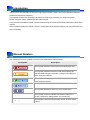
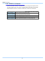
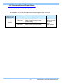
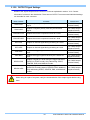
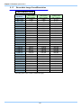
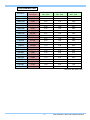
Details of the signals output from the OUTPUT connector explained in section “3.12. Contact
Information” is shown in the chart below. There are two OUTPUT connectors and individual settings
can be made for each connector.
Menu Display
Contents
Signal Type
SYNC POS
Outputs a positive polarity vertical synchronization
signal.
+5V CMOS output,
Positive Polarity
SYNC NEG
Outputs a negative polarity vertical synchronization
signal.
+5V CMOS output,
Negative Polarity
EXPOSE POS
Outputs the sensor's exposure interval at H level.
+5V CMOS output,
Positive Polarity
EXPOSE NEG
Outputs the sensor's exposure interval at L level.
+5V CMOS output,
Negative Polarity
REC POS
Outputs an interval signal during recording at H level.
+5V CMOS output,
Positive Polarity
REC NEG
Outputs an interval signal during recording at L level.
+5V CMOS output
Negative Polarity
TRIG POS
Outputs the trigger signal received by the camera at H
level.
+5V CMOS output,
Positive Polarity
TRIG NEG
Outputs the trigger signal received by the camera at L
level.
+5V CMOS output,
Negative Polarity
READY POS
Outputs a signal at H level during the trigger wait state.
(READY in START mode.) Only valid during START,
CENTER, END, and MANUAL modes.
+5V CMOS output,
Positive Polarity
READY NEG
Outputs a signal at L level during the trigger wait state.
(ENDLESS recording state in CENTER, END, MANUAL)
Only valid during START, CENTER, END, and MANUAL
modes.
+5V CMOS output,
Negative Polarity
When using as a part of a system, verify the characteristics of the output signals before using
them.
49
FASTCAM Mini UX50/100 Hardware Manual