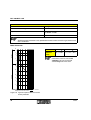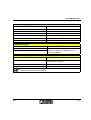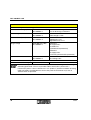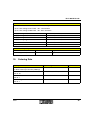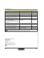
1
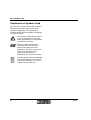
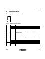
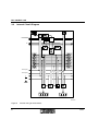
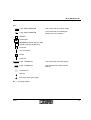
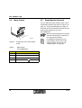
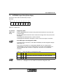
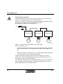
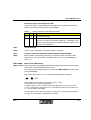
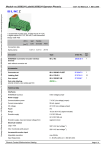
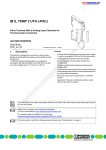
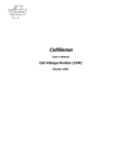
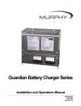
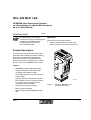
IB IL 400 MLR 1-8A
INTERBUS Inline Power-Level Terminal
as a Direct Starter for a Motor With a Power of
up to 3.7 kW (4.958 hp)
Data Sheet 6049D
11/2000
This data sheet is only valid in
association with the "Configuring and
Installing the INTERBUS Inline
Product Range" User Manual
IB IL SYS PRO UM E.
Application
Three-phase asynchronous motors
–
Nominal voltage 400 V AC or 500 V AC
–
Nominal motor current from 0.2 A to 8.0 A
Product Description
The single-channel power-level terminal with
electronic motor protection provides switching,
protection and monitoring of three-phase
asynchronous motors via INTERBUS. The
power-level terminal is designed for use within
the 24 V area of an INTERBUS Inline station.
Features
–
INTERBUS protocol (EN 50254:1997)
–
Integrated electronic motor protection
according to IEC 60947-4:1990
–
Connection option for an external passive
brake module
–
Operator Hand Panel operation possible
–
Safe isolation or basic insulation between
line voltage and 24 V supply voltage
according to EN 50178:1997
–
Diagnostic and status indicators
–
Motor current monitoring
–
Motor control through INTERBUS output
data
6049D
6 0 4 9 A 0 0 1
Figure 1
The IB IL 400 MLR 1-8A
power-level terminal
1
IB IL 400 MLR 1-8A
Explanation of Symbols Used
This data sheet contains information that must
be noted for your own safety and to avoid
damage to equipment. This information is
marked with the following symbols according to
the level of danger:
The attention symbol refers to actions
that may endanger the health and
safety of personnel, or cause damage
to hardware or software.
The note symbol informs you of
conditions that must strictly be
observed to achieve error-free
operation. It also gives you tips and
advice on the efficient use of
hardware and on software
optimization to save you extra work.
The text symbol refers you to detailed
sources of information (user manuals,
data sheets, literature, etc.) on the
subject matter, product, etc.
2
6049D
IB IL 400 MLR 1-8A
Safety Instructions for Electrical Equipment Used in
High-Power Industrial Plants
The electrical power-level terminal and
connected machines described are equipment
used in high-power industrial plants. During
operation, this equipment has dangerous, live,
moving, or rotating parts. They can therefore
cause considerable damage to health or
equipment, e.g., due to the unauthorized
removal of protective covers or inadequate
maintenance.
–
Only qualified personnel may work on the
power-level terminal or system.
–
When work is being carried out on the
power-level terminal or system, the
operation manual and the relevant product
documentation must always be kept at hand
and referred to.
–
It is prohibited for unqualified personnel to
work on the power-level terminal, on the
machines or in their vicinity.
The process notes and circuit details presented
in this data sheet should be understood in a
general sense and the relevant application
should be tested to see if they apply.
Phoenix Contact cannot guarantee the suitability
of the procedures described or the circuit
suggestions for the relevant application.
The instructions given in this data sheet must be
followed during installation and startup.
Technical modifications reserved.
Qualified personnel are people who, because of
their education, experience and instruction and
their knowledge of relevant standards,
regulations, accident prevention and service
conditions, have been authorized by those
responsible for the safety of the plant to carry out
any required operations and who are able to
recognize and avoid any possible dangers.
(Definitions for skilled workers according to
EN 50110-1:1996.)
6049D
3
IB IL 400 MLR 1-8A
4
6049D
IB IL 400 MLR 1-8A
Table of Contents
1 Correct Usage ........................................................................................................................... 6
2 Installation Instructions ............................................................................................................. 6
3 General Description .................................................................................................................. 7
3.1 Diagnostic and Status Indicators .................................................................................. 7
3.2 Internal Circuit Diagram ................................................................................................ 8
4 Safety and Warning Instructions ............................................................................................... 10
5 Connections .............................................................................................................................. 10
5.1 Terminal Strips of the Power-Level Terminal ................................................................ 11
5.2 INTERBUS and Low Level Signals ............................................................................... 12
5.3 Incoming and Outgoing Lines ....................................................................................... 12
5.4 Motor Output ................................................................................................................. 14
5.5 Brake Module (Optional) ............................................................................................... 14
5.6 Manual Mode (Operator Hand Panel Operation) .......................................................... 15
5.7 Enabling the Power Level/24 V Isolation ....................................................................... 17
5.8 Connections to a Power-Level Terminal ....................................................................... 18
5.9 Wiring Example ............................................................................................................. 19
6 Programming Data .................................................................................................................... 19
7 INTERBUS Process Data ......................................................................................................... 20
7.1 Assignment of the Power-Level Terminal Input and Output Data to the INTERBUS
Process Data ................................................................................................................ 20
7.2 INTERBUS Output Data ............................................................................................... 21
7.2.1 Control Byte ................................................................................................................ 25
7.3 INTERBUS Input Data (Status Byte) ............................................................................. 29
8 Description of Functions ........................................................................................................... 34
8.1 Manual Mode ................................................................................................................ 34
8.2 Shutdown Behavior in the Event of Errors .................................................................... 35
8.3 Restart Behavior After an Error .................................................................................... 35
8.4 INTERBUS Reset or INTERBUS Not Active ................................................................ 36
8.5 Thermal Motor Protection Through the Inline Thermistor Terminal (Optional) ............. 36
8.6 Brake (Optional) ............................................................................................................ 37
9 Technical Data .......................................................................................................................... 38
10 Ordering Data ........................................................................................................................... 45
6049D
5
IB IL 400 MLR 1-8A
1
Correct Usage
The power-level terminal is only to be used as specified in the catalog and this data sheet. Phoenix
Contact accepts no liability if the device is used for anything other than its designated use.
2
Installation Instructions
Do not replace terminals while
power is connected.
Take measures to suppress
interference.
Before removing or mounting an
Inline terminal, disconnect power to
the entire station. Make sure the
entire station is reassembled before
switching the power back on.
Switching three-phase induction
motors when they are not at zero
current generates electromagnetic
disturbance, which may adversely
affect the function of the system. In
order to limit this type of interference,
appropriate measures must be taken
in accordance with standard EN
60204-1:1998 (Electrical Equipment
of Machines) to attenuate the
interference at its source (the motor).
In practice, RC interference
suppression elements have proven to
be effective.
Dangerous voltage
Before working on the power-level
terminal or system, disconnect the AC
line voltage and ensure that it cannot
be switched on again.
If these instructions are not followed,
there is a danger of damage to health,
or even of a life-threatening injury.
Additional information on mounting
and installing the power-level terminal
and general information on the
INTERBUS Inline product range can
be found in the "Configuring and
Installing the INTERBUS Inline
Product Range" User Manual
IB IL SYS PRO UM E.
6
6049D
IB IL 400 MLR 1-8A
3
General Description
3.1
Diagnostic and Status Indicators
D
E R R
M 1
L O C
6 0 4 9 0 0 0 2
Figure 2
D
Diagnostic and status indicators
Green LED
Diagnostics
ON:
INTERBUS is active
Flashing:
ERR
M1
LOC
6049D
0.5 Hz:
(slow)
Communications power is present, INTERBUS is not active
4 Hz:
(fast)
Communications power is present,
bus connection for the flashing terminal has failed;
terminals to the right of the flashing terminal are not part of the
configuration frame
OFF:
Communications power is not present, INTERBUS is not active
Red LED
Group error message/motor protection
ON:
Operational fault
(motor protection has been triggered, power level cannot be controlled)
OFF:
No error
Yellow LED
Motor
ON:
Motor is switched on
OFF:
Motor is not switched on
Yellow LED
Manual mode (local)
ON:
Manual mode is active
OFF:
Manual mode is not active
7
IB IL 400 MLR 1-8A
3.2
Internal Circuit Diagram
IN T E R B U S
U
O P C
L
I
U
+ 2 4 V (U
+ 2 4 V (U
M
S
L 1
L 1
L 2
L 2
L 3
L 3
N
N
P E
P E
)
)
6 0 4 9 B 0 0 3
Figure 3
8
Internal wiring of the terminals
6049D
IB IL 400 MLR 1-8A
Key:
4-pos. MINI-COMBICON
(X32, connection for manual mode)
2-pos. MINI-COMBICON
(X18, connection for enabling the
power level / 24 V isolation
Amplifier
Optocoupler
OPC
INTERBUS protocol chip (bus logic
including voltage conditioning)
Converter
L 1
L 2
L 3
N
Line connection
P E
Switch
Capacitor
4-pos. COMBICON
(X10, connection for motor output)
3-pos. COMBICON
(X8, connection for external brake
module)
Isolated area
Ground
Functional earth ground (FE)
Voltage jumper
6049D
9
IB IL 400 MLR 1-8A
4
5
Safety and Warning Instructions
Dangerous voltage
Avoid damage to the electronics
Carry out all work on the power-level
terminal and the connectors when the
power is not connected.
Do not mix up the terminals, as this
may damage the electronics.
Connections
Observe the safety and warning
instructions listed under 4.
The power-level terminals with all
(including optional) connectors can
be found in Figure 12 on page 18.
10
6049D
IB IL 400 MLR 1-8A
5.1
Terminal Strips of the Power-Level Terminal
X 3 2
X 1 8
1
X 1 1
X 1 2
2
X 8
X 1 0
Figure 4
6 0 4 9 A 0 0 4
Connections
1
Data jumper for INTERBUS
2
Voltage jumper for the low level signals
UM, US, UANA, UL, GND, FE
X8
Connection for an external brake module
including brake switch and connection for brakes (X9)
See Figure 12 on page 18
X10
Connection for the motor output
See Figure 8 on page 14
X11
Connection for the incoming line
L1, L2, L3, N, PE
X12
Connection for the outgoing line
L1, L2, L3, N,
X18
Enabling the power level / 24 V isolation
See Figure 11 on page 17
X32
Connection for manual mode
(Operator Hand Panel operation; HVO)
See Figure 9 on page 16
6049D
11
IB IL 400 MLR 1-8A
5.2
INTERBUS and Low Level Signals
Connecting the power-level terminal to the
previous terminal of an Inline station creates the
voltage jumpers for INTERBUS and the low level
signals.
5.3
For additional information, please
refer to the INTERBUS Inline System
Manual.
Incoming and Outgoing Lines
L 1
L 1
L 2
L 2
L 1
L 2
L 3
L 3
N
N
P E
L 3
N
6 0 4 9 0 0 0 7
Figure 5
12
Assignment of the X11 and X12
slots (with connected power
connector)
6049D
IB IL 400 MLR 1-8A
There are two ways of connecting the incoming line to the power-level terminal:
1
Connect the incoming line using a power
connector.
2
If several power-level terminals are to be
connected one after the other, it is possible
to connect one power-level terminal to the
preceding power-level terminal using a
power bridge. If the preceding terminal is
connected to the power supply, power is
transmitted via the power bridge.
6 0 4 9 0 0 0 5
Figure 6
Connection of a power connector
6 0 4 9 0 0 0 6
Figure 7
Inserting a power bridge
Ordering data for power connector and power bridge can be found on page 45.
Table 1
Incoming/outgoing line
X11 (LINE IN)
X12 (LINE OUT; Power Bridge)
L1
L1
L2
L2
L3
L3
N
N
PE
The N wire is not required to operate this power-level terminal.
6049D
13
IB IL 400 MLR 1-8A
5.4
Motor Output
5.5
Brake Module (Optional)
You can order the brake module, which can be
connected to terminal strip X8 (see Figure 4 on
page 11), using the ordering data on page 45.
The brake is then connected to terminal strip X9
of this brake module using a 2-pos.
HV-COMBICON.
2
3
1
Figure 8
Table 2
14
Make sure that the brake is connected
with the correct polarity, otherwise it
may not operate correctly.
4
6 0 4 9 A 0 2 0
Assignment of the motor output
(X10)
For additional information on the
brake module, please refer to the
module-specific data sheet (see
"Ordering Data" on page 45).
Motor output
(HV-COMBICON)
Pin
X10 (Motor)
1
Motor: T1
2
Motor: T2
3
Motor: T3
4
Motor:
6049D
IB IL 400 MLR 1-8A
5.6
Manual Mode (Operator Hand
Panel Operation)
In manual mode, all motor
protection functions are
deactivated.
Manual mode has priority over
INTERBUS operation.
The motor protection relay function
has no effect in manual mode.
The MINI-COMBICON connector for the
connection of an Operator Hand Panel (X32) is
under the upper release flap.
When manual mode is activated, the
power-level terminal can be controlled locally,
independently of the INTERBUS system. For
this, the "motor ON/OFF" functions are
available.
Manual mode is controlled using a temporarily
connected external Operator Hand Panel. This
is connected to the power-level terminal using a
4-pos. MINI-COMBICON. The slot is under the
upper release flap (see Figure 9 on page 16).
The Operator Hand Panel can only be
connected when the release flap is upright.
You can order the Operator Hand
Panel using the Ordering Data on
page 45.
When manual mode is enabled on the powerlevel terminal, the LOC status indicator lights up
(see Figure 2 on page 7).
After manual mode has been activated on the
power-level terminal, HVO (manual mode
acknowledgment) is automatically set in the
input data (see "INTERBUS Input Data (Status
Byte)" on page 29).
6049D
15
IB IL 400 MLR 1-8A
Table 3
2
Pin
X32 (Operator
Hand Panel)
Function
1
Reserved
Reserved
2
Input E 8
Motor in manual
mode
3
Input E 10
Enable manual
mode
4
US
24 V segment
voltage
4
3
1
Figure 9
X32 Operator Hand Panel (MINICOMBICON)
6 0 4 9 A 0 2 1
Assignment of connections for the
Operator Hand Panel (X32)
Manual mode is activated automatically by connecting an Operator Hand Panel.
The terminal point "24 V segment voltage" is not protected against short-circuits and
overloads inside the terminal. Provide short-circuit protection for the segment voltage
supply (e.g., on the power terminal or segment terminal).
Table 4
Signal assignment of the manual mode inputs
Function
Enable
Motor
Key:
Enable manual mode
1
0
0
Input signal "Low", binary "0"
Motor in manual mode
1
1
1
Input signal "High", binary "1"
No manual mode
0
X
X
Any kind of input signal
(Please note the special features in direct
mode)
X 3 2 P in 4
E n a b le
M o to r
X 3 2 P in 3
X 3 2 P in 2
6 0 4 9 0 0 1 4
Figure 10 Function block diagram of an Operator Hand Panel
It is also possible to use pin 2 of terminal strip X32 to control the motor in direct mode
(see "DM: (Bit 3)" on page 26).
16
6049D
IB IL 400 MLR 1-8A
5.7
Enabling the Power Level/24 V Isolation
The MINI-COMBICON connector for the X18
terminal strip (Enabling the power level/24 V
isolation) is under the upper release flap.
1
2
MINI-COMBICON. Without "Enabling the power
level", the power level cannot be controlled, the
contactor is always dropped out (contacts open)
and the brake is always applied (motor is
decelerated).
The segment voltage US is used to enable the
power level, which can be made available using
a jumper or a switch:
1
The X18 terminal strip is supplied as
standard with a jumper inserted between
pins 1 and 2.
If no switch is connected to X18, the jumper
can remain inserted. The power level of the
power-level terminal is enabled by the
directly available 24 V segment voltage.
2
If an external switch is connected between
pins 1 and 2 on the X18 terminal strip, the
power level of the power-level terminal is
enabled when closed.
6 0 4 9 A 0 2 2
Figure 11 Assignment of the "Enabling the
power level" (X18) connection
Table 5
Enabling the X18 power level
(MINI-COMBICON)
Pin
X18 (Enable)
1
1 (24 V segment voltage US)
2
2 (enable power level)
No internal terminal protection
against short-circuit/overload
The "24 V segment voltage" terminal
point is not protected against shortcircuits and overloads inside the
terminal. Provide short-circuit
protection for the segment voltage
supply (e.g., on the power terminal or
segment terminal).
The control voltage for the power level and the
brake is supplied using pin 2 of the 2-pos.
6049D
17
IB IL 400 MLR 1-8A
5.8
Connections to a Power-Level Terminal
7
2
1
6
5
4
3
6 0 4 9 A 0 0 9
Figure 12 Power-level terminal with all connections
1
X11
Incoming line
(here: power connector)
5
X9
Connection of the brake to the
brake module
2
X12
Outgoing line
(power bridge)
6
X32
Operator Hand Panel
3
X10
Motor output
7
X18
Enabling the power level
4
X8
Brake module
18
6049D
IB IL 400 MLR 1-8A
5.9
Wiring Example
IB IL 4 0 0 M L R
1
T 1 T 2 T 3
IB IL 4 0 0 M L R
2
Avoid short-circuits
It is not possible to interlock the
terminals using the hardware. Thus it
is necessary to interlock the terminals
using the software in the control
system.
A phase-to-phase short-circuit may occur if the
reversing application is switched too fast. This is
the case if the arc of the contactor switching off
has hot extinguished yet and the contacts of the
contactor switching on have already been
closed. To avoid this risk both power-level
terminals (contactor coils) must be switched off
during reversing for a minimum of 100 ms.
T 1 T 2 T 3
Please note that interlocking is not
possible in manual mode.
For the future it is planned to provide
function blocks to create interlocking
via the Internet.
M
3 ~
6 0 4 9 B 0 2 3
Figure 13 Wiring of two IB IL 400 MLR 1-8A
power-level terminals to obtain a
reversing application
6
Programming Data
ID code
BFhex (191dec)
Length code
81hex (129dec)
Process data channel
8 bits
Input address area
1 byte
Output address area
1 byte
Parameter channel (PCP)
0 bytes
Register length
1 byte
6049D
19
IB IL 400 MLR 1-8A
7
INTERBUS Process Data
7.1
Assignment of the Power-Level Terminal Input and Output Data to the
INTERBUS Process Data
Assignment of Power-Level Terminal Output Data to the INTERBUS Output Data Byte
(Control Byte)
Assignment
M
RESET
M
Motor ON/OFF
RESET
Error acknowledgment
IMIN
Minimum current checking
DM
Direct Mode
EBC
Enable Brake Control
BR
Brake
RES_XX
Reserved
4
3
2
1
0
BR
5
EBC
6
RES_01
7
DM
Bit
IMIN
Byte 0
Byte
RES_02
(Byte.Bit)
View
Assignment of Power-Level Terminal Output Data to the INTERBUS Output Data Byte
(Parameterization Byte)
(Byte.Bit)
View
Byte 0
Byte
Bit
Assignment
7
20
5
4
3
2
1
0
P7 P6 P5 P4 P3 P2 P1 P0
1
P7 to P0
6
1
Nominal current code
Parameterization bits
6049D
IB IL 400 MLR 1-8A
Assignment of Power-Level Terminal Input Data to the INTERBUS Input Data Byte
Byte 0
7
6
5
4
3
2
1
Assignment
RUN
HVO
MB3
MB2
MB1
0
MB0
Bit
F0
Byte
F1
(Byte.Bit)
View
F1 and F0
Diagnostic code
RUN
Motor running
HVO
Operator Hand Panel Operation acknowledgment (manual mode)
MB3 to MB0
Motor current monitoring
For the assignment of the output and input data bytes to the user set control or computer
system, please refer to data sheet DB GB IBS SYS ADDRESS, Part. No. 90 00 99 0.
7.2
INTERBUS Output Data
For the Inline power-level terminal, one byte is
available for output data.
If bits 7 and 6 of the output data byte are set
(code 11bin), this byte is used for
parameterization (parameterization byte), and
the power-level terminal is in parameterization
mode. In this mode, the nominal motor current is
transmitted as an operating parameter.
If the code of bits 7 and 6 of the output data byte
is not equal to 11bin, then process data is being
transmitted (control byte). The power-level
terminal is in process data mode. In this
operating mode, the power-level terminal
function is affected by the process data.
6049D
7.2.1
Parameterization of the Nominal
Motor Current
The motor is automatically switched
off during parameterization.
If the 7.5 V power supply UL fails, the
parameter settings will not be stored.
In this case you will have to
parameterize the power-level terminal
again.
The diagnostic code 00bin is displayed after
every successful parameterization.
Parameterizing the nominal motor current
serves as an overcurrent protection. The
parameter is the nominal current of the drive
(nominal motor current). The nominal motor
current that can be set ranges from 0.2 A to
8.0 A. The nominal motor current is specified
through bits 5 to 0 of the parameterization byte.
21
IB IL 400 MLR 1-8A
B it 7
P 7
6
5
4
3
2
1
0
P 6
P 5
P 4
P 3
P 2
P 1
P 0
For a nominal motor current ranging from 3.2 A
to 8.0 A (in steps of 200 mA) the nominal current
code is calculated according to equation 3:
C O D E
1
N o m in a l c u r r e n t c o d e
1
6 0 4 9 0 0 1 0
Figure 14 Parameterization of the nominal
motor current
=
In
o m
+ 4 .6 A
0 .2 A
If you do not parameterize the
nominal motor current or if you enter a
nominal current code of 0, the default
value of Inom = 0.2 A is valid.
There is no linear relationship between nominal
motor current and nominal current code. Steps
of 50 mA, 100 mA and 200 mA are used. For the
nominal current code, refer to Table 6 on
page 23 or calculate it yourself.
When calculating the three motor current
ranges, note that three different equations must
be used.
For a nominal motor current ranging from 0.2 A
to 1.2 A (in steps of 50 mA) the nominal current
code is calculated according to equation 1.
C O D E
With:
Inom
In
=
- 0 .2 A
0 .0 5 A
o m
Nominal current Inom in A
CODE Nominal current code
For a nominal motor current ranging from 1.3 A
to 3.0 A (in steps of 100 mA) the nominal current
code is calculated according to equation 2.
C O D E
22
=
In
o m
+ 0 .8 A
0 .1 A
6049D
IB IL 400 MLR 1-8A
Table 6
Inom
[A]
0.20
0.25
0.30
0.35
0.40
0.45
0.50
0.55
0.60
0.65
0.70
0.75
0.80
0.85
0.90
0.95
1.00
1.05
1.10
1.15
1.20
1.30
1.40
1.50
1.60
1.70
Assignment of the nominal current code to the nominal motor current
CODE
dec (hex)
Bits 5 to 0
Byte
0 (00)
1 (01)
2 (02)
3 (03)
4 (04)
5 (05)
6 (06)
7 (07)
8 (08)
9 (09)
10 (0A)
11 (0B)
12 (0C)
13 (0D)
14 (0E)
15 (0F)
16 (10)
17 (11)
18 (12)
19 (13)
20 (14)
21 (15)
22 (16)
23 (17)
24 (18)
25 (19)
192 (C0)
193 (C1)
194 (C2)
195 (C3)
196 (C4)
197 (C5)
198 (C6)
199 (C7)
200 (C8)
201 (C9)
202 (CA)
203 (CB)
204 (CC)
205 (CD)
206 (CE)
207 (CF)
208 (D0)
209 (D1)
210 (D2)
211 (D3)
212 (D4)
213 (D5)
214 (D6)
215 (D7)
216 (D8)
217 (D9)
Inom
[A]
1.80
1.90
2.00
2.10
2.20
2.30
2.40
2.50
2.60
2.70
2.80
2.90
3.00
3.20
3.40
3.60
3.80
4.00
4.20
4.40
4.60
4.80
5.00
5.20
5.40
5.60
CODE
dec (hex)
Bits 5 to 0
Byte
26 (1A)
27 (1B)
28 (1C)
29 (1D)
30 (1E)
31 (1F)
32 (20)
33 (21)
34 (22)
35 (23)
36 (24)
37 (25)
38 (26)
39 (27)
40 (28)
41 (29)
42 (2A)
43 (2B)
44 (2C)
45 (2D)
46 (2E)
47 (2F)
48 (30)
49 (31)
50 (32)
51 (33)
218 (DA)
219 (DB)
220 (DC)
221 (DD)
222 (DE)
223 (DF)
224 (E0)
225 (E1)
226 (E2)
227 (E3)
228 (E4)
229 (E5)
230 (E6)
231 (E7)
232 (E8)
233 (E9)
234 (EA)
235 (EB)
236 (EC)
237 (ED)
238 (EE)
239 (EF)
240 (F0)
241 (F1)
242 (F2)
243 (F3)
Inom
[A]
5.80
6.00
6.20
6.40
6.60
6.80
7.00
7.20
7.40
7.60
7.80
8.00
CODE
dec (hex)
Bits 5 to 0
Byte
52 (34)
53 (35)
54 (36)
55 (37)
56 (38)
57 (39)
58 (3A)
59 (3B)
60 (3C)
61 (3D)
62 (3E)
63 (3F)
244 (F4)
245 (F5)
246 (F6)
247 (F7)
248 (F8)
249 (F9)
250 (FA)
251 (FB)
252 (FC)
253 (FD)
254 (FE)
255 (FF)
The binary nominal current code of bits 5 to 0 of the parameterization byte or of the
entire byte corresponds to the decimal or hexadecimal value given in the table.
6049D
23
IB IL 400 MLR 1-8A
Example for Power-Level Terminal Parameterization
Parameterize with the value: nominal motor current = 2.5 A.
The bit sequence for the nominal current code to be entered in the
parameterization byte can be calculated or read from Table 6 on page 23.
Calculation
The motor current Inom = 2.5 A is in the range between 1.3 A and 3.0 A. The
result according to equation 2 is:
C O D E
Reading from
the table
=
In
o m
+
0 .8 A
0 .1 A
=
2 .5 A + 0 .8 A
0 .1 A
= 3 3
d e c
= 2 1
h e x
= 1 0 0 0 0 1
b in
Table 6 shows a nominal current code (bits 5 to 0) of 21hex = 10 00 01bin for
Inom= 2.5 A.
Table 6 also shows the value for the entire byte for Inom= 2.5 A. This is
225dec = E1hex = 1110 0001dec.
Result
The parameterization byte is E1hex
(nominal current code = 10 00 01bin; byte = 11 10 00 01bin).
7
6
1
1
5
1
4
3
2
1
Nominal current code
0
0
E
The
parameterization
procedure
0
1
1
Step
Output
Data Byte
1
E1hex
2
3
0
0
Diagnostic Remark
Code
Specification of the nominal current = 2.5 A
<>01bin
00hex
Wait until a diagnostic code not equal to 1
is returned;
No error: diagnostic code = 0
Parameterization completed
In the example, parameterization is completed and you can switch over to
process data operation with the control byte (see "Control Byte" on page 25).
24
6049D
IB IL 400 MLR 1-8A
7.2.2
Control Byte
The control byte transmits process data in the output data byte.
Before you can work with the control byte, you must specify the nominal motor current (see
"Parameterization of the Nominal Motor Current" on page 21).
B it
7
R E S
0 2
M
6
5
4
R E S E T
IM IN
3
2
1
0
D M
R E S
0 1
E B C
B R
6 0 4 9 0 0 1 1
Figure 15 Control byte
RES_02:
Reserved
(Bit 7)
Set the reserved bit to 0.
M:
Motor ON/OFF
(Bit 6)
M switches the motor on and off. If the brake module is connected, M closes and
opens the brake switch as long as it has not been defined as freely controllable.
M=1
Motor ON, brake switch closed (brake is released)
M=0
Motor OFF, brake switch open (motor is decelerated)
RESET:
Error Acknowledgment
(Bit 5)
By setting RESET you can acknowledge an error that caused the motor to shut
down, after the error cause has been removed. RESET must remain set until the
error message is reset.
Avoid damage to motor, power-level terminal or persons.
If in the event of a critical error you repeatedly issue a RESET without rectifying
the fault, this may result in damage to the motor, the power-level terminal or to
persons.
Local Error Acknowledgment via the Bus or at the Power-Level Terminal
The enable input X32, pin 3, provides another method of error acknowledgment. If
you enable manual mode, an error that has occurred is reset. This means that by
inserting the IBS HVO Operator Hand Panel (see Ordering Data on page 45), the
error status can be reset locally (see also "HVO:" on page 31).
6049D
25
IB IL 400 MLR 1-8A
IMIN:
Minimum Current Check
(Bit 4)
Bit 4 = 0:
A check of the minimum current is carried out. If the current of an
activated power level is < 160 mA, the motor switches off and
generates the error message "Power level cannot be controlled".
Bit 4 = 1:
A check of the minimum current is not carried out. No minimum
current must be kept.
Avoid damage to the motor
Complete motor protection is not possible in this operating mode because twophase operation of the motor is not detected.
DM:
(Bit 3)
Direct Mode
The "Enable manual mode" input (X32 pin 3) must be set to 0 for this operating
mode.
Bit 3 = 0:
No direct mode.
Bit 3 = 1:
Direct mode. The motor is directly switched by the manual mode input
(X32 pin 2).
The motor can no longer be controlled by the process data (bit 6) in
this operating mode.
The protection is the same as when switching via INTERBUS
(overcurrent, minimum current).
RES_01
Reserved
(Bit 2)
Set the reserved bit to 0.
26
6049D
IB IL 400 MLR 1-8A
EBC:
(Bit 1)
Enable Brake Control
The descriptions for the brake switch and for the brake only apply when the brake
module is connected to the X8 terminal strip of the power-level terminal and the
brake is connected to the X9 terminal strip of the brake module.
EBC enables free control of the brake switch (and also the brake).
If EBC = 1, the brake switch can be freely controlled i.e., independently of the
motor control (M). In this case, the brake switch is controlled with BR.
If EBC = 0, the brake switch cannot be freely controlled. It is controlled through the
motor controller (M).
In "Enable brake control" operating mode, the user has to control the brake even
if an error occurs (F1 in the diagnostic code = 1).
BR:
(Bit 0)
Brake (With Freely Controllable Brake (EBC = 1))
The descriptions for the brake switch and for the brake only apply when the brake
module is connected to the X8 terminal strip of the power-level terminal and the
brake is connected to the X9 terminal strip of the brake module.
In "Enable brake control" operating mode, the operator has to control the brake.
The brake switch is closed by setting BR (BR = 1). The brake is released and the
motor enabled.
When the bit is set to zero (BR = 0), the brake switch is opened, the brake takes
effect and the motor is decelerated.
Manual mode and an INTERBUS reset are special cases in this operating mode.
In these cases, the brake is automatically controlled.
In "Enable brake control" operating mode, the user has to control the brake even
if an error occurs (F1 in the diagnostic code = 1).
If bit 1 (EBC) is reset to 0, the brake is set depending on the motor status. If the
motor is on, the brake is released. If the motor is off, the brake is applied.
6049D
27
IB IL 400 MLR 1-8A
Table 7
Relationship between EBC and BR
EBC (Bit 1) Meaning
28
BR (Bit 0)
Meaning
0
Brake switch not freely
controllable
X
No function
1
Brake switch freely
controllable
0
Brake switch open, motor
is decelerated
1
Brake switch closed,
motor is enabled
6049D
IB IL 400 MLR 1-8A
7.3
INTERBUS Input Data (Status Byte)
The status of the motor is indicated by an input
data byte.
B it 7
F 1
6
5
4
F 0
R U N
H V O
3
2
M B 3 M B 2
1
0
M B 1
M B 0
6 0 4 9 0 0 1 2
Figure 16 Status byte
F1 and F0:
Diagnostic Code
(Bit 7 and
bit 6)
Bits F1 and F0 indicate the status of the power-level terminal or any errors that
have occurred.
F1 (bit 7) differentiates between status and error messages. F1 is only set for error
messages.
If the diagnostic code equals 0, no error occurred.
If the diagnostic code does not equal 0, status or error messages are present.
Error Messages in the Diagnostic Code
If an error occurs, the motor is shut down immediately and the diagnostic display
(ERR) lights up.
The error that occurred first is indicated by RESET until it is removed and
acknowledged . The message is deleted once it has been acknowledged (see
"Restart Behavior After an Error" on page 35). Only then can the motor be
restarted.
Table 8
Error messages in the diagnostic code
Code
F1
F0 Description
11bin
1
1
Overcurrent;
is generated if overcurrent protection has been triggered
10bin
1
0
Power level cannot be controlled
During error-free operation, the control system only needs to evaluate F1 (bit 7).
If F1 is set, a subprogram can be called to evaluate the diagnostic code.
6049D
29
IB IL 400 MLR 1-8A
Avoid damage to the motor
The motor will not shut down automatically every time the error message 10bin
appears in the diagnostic code (e.g., sticking contactors).
In this case, you must also ensure that the 400 V operating voltage of the powerlevel terminal is switched off to avoid damaging the motor.
An example of shutdown is shown in Figure 17.
L in e
3
K 1
M o to r s ta rte r
M
3 ~
M o to r s ta rte r
M
3 ~
M o to r s ta rte r
M
3 ~
6 0 0 9 0 0 1 9
Figure 17 Example of disconnecting the operating voltage
Error message 10bin is set:
–
If the control signal for the power level is present and the minimum permissible
motor current of 0.16 A is not reached (this only applies if bit 4 (IMIN) is not
set).
–
If the control signal for the power level is not present and the measured motor
current is greater than 0.16 A (sticking contactors).
The error message is generated if the error lasts for more than 1 second.
These errors are caused by defective power levels, sticking contactors or the
interruption of a phase in the motor supply.
If the 10bin error message occurs, the application program can evaluate the error
type. In addition to the error message, the application program must evaluate
control signal M (bit 6 of the output data byte).
30
6049D
IB IL 400 MLR 1-8A
Status Messages in the Diagnostic Code
If status messages are generated, this does not cause the motor to shut down.
Status messages do not need to be acknowledged.
Table 9
Status messages in the diagnostic code
Code
F1
F0 Description
0hex
0
0
No status message
1hex
0
1
Parameterization not yet carried out
The bit is set after the operating voltage UL is switched on and
after a restart (voltage reset). It indicates that the motor has not
yet been parameterized.
RUN:
"Motor Running"
(Bit 5)
The bit is set if the power level (motor output) is controlled.
HVO:
Operator Hand Panel Operation Acknowledgment (Manual Mode)
(Bit 4)
Manual mode is activated by connecting an Operator Hand Panel to the X32
terminal strip. If manual mode is activated, HVO is set as an acknowledgment
(HVO = 1).
MB3 to MB0:
Motor Current Monitoring
(Bit 3 to bit 0) The motor current monitoring indicates the relationship between the actual motor
current and the parameterized motor current.
The motor current monitoring code α can be read in MB3 to MB0 of the input data
byte in INTERBUS.
The motor current ratio Iact/Inom is calculated according to the equation:
Ia
c t
In
o m
=
3 2
+ 0 .7 5
The resolution of the motor current ratio Iact/Inom is 1/32.
Values of 0 to 15 can be transmitted for α.
A range of 0.75 to 1.22 is covered, with offset taken into account, for the ratio
Iact/Inom. If the motor current ratio Iact/Inom exceeds the value 1.22 the value 1.22
(α = 15) will still be transmitted.
For the motor current ratio, the current Iact of phase T1 is evaluated (see Table 2
on page 14). The display is updated every 120 ms.
6049D
31
IB IL 400 MLR 1-8A
Motor Current Ratio α
Mapped to the Input Byte
β=
Iact/Inom
in %
Iact/
Inom
Dec
Motor Current Ratio α
Mapped to the Input Byte
Iact/
Inom
β=
Iact/Inom
in %
Dec
MB3 MB2 MB1 MB0
MB3 MB2 MB1 MB0
0
0
0
0
0
≤ 0.75
≤ 75
1
0
0
0
8
1.00
100
0
0
0
1
1
0.78
78
1
0
0
1
9
1.03
103
0
0
1
0
2
0.81
81
1
0
1
0
10
1.06
106
0
0
1
1
3
0.84
84
1
0
1
1
11
1.09
109
0
1
0
0
4
0.88
88
1
1
0
0
12
1.13
113
0
1
0
1
5
0.91
91
1
1
0
1
13
1.16
116
0
1
1
0
6
0.94
94
1
1
1
0
14
1.19
119
0
1
1
1
7
0.97
97
1
1
1
1
15
≥ 1.22
≥ 122
Calculation of the Motor Current
The following equations are available for calculating the actual motor current from
the motor current ratio:
Equation 1
= (
3 2
+ 0 .7 5 ) x 1 0 0 %
=
Ia
c t
In
o m
x 1 0 0 %
Equation 2
Ia
c t
= (
3 2
+ 0 .7 5 ) x In
o m
With:
α
The motor current ratio mapped to the input data byte represented as a
decimal value
β
Iact as a percentage value of Inom
Inom Parameterized nominal motor current Inom in A
Iact
32
Measured motor current Iact in A
6049D
IB IL 400 MLR 1-8A
Example for Calculating the Motor Current:
Parameterized nominal motor current:
1.1 A (= 12hex = 10010bin in the output data byte, bits 5 to 0 (MB5 to MB0))
Indicator in MB3 to MB0: 0011bin = 3dec = α
According to equation 1:
= (
3
3 2
+ 0 .7 5 ) x 1 0 0 %
= 8 4 %
The actual motor current is 84% of the parameterized nominal motor current.
According to equation 2:
Ia
c t
= (
3
3 2
+ 0 .7 5 ) x 1 .1 A = 0 .9 3 A
The actual motor current is 0.93 A.
6049D
33
IB IL 400 MLR 1-8A
8
Description of Functions
8.1
Manual Mode
In manual mode, all motor
protection functions are
deactivated.
If the "Enable manual mode" input is connected
to the power-level terminal, manual mode has
priority over INTERBUS operation. Manual
mode is enabled via two inputs.
Input functions:
E10
→ Enable manual mode
E8
→ Motor in manual mode
(See "Manual Mode (Operator Hand Panel
Operation)" on page 15)
Delay Time
When enabling or disabling manual mode, the
firmware maintains a delay time of 1 second.
During the delay time, the power-level terminal
switches the motor off. If a brake switch is
connected, it opens.
In manual mode, free control of the brake is
ignored, so that the brake is automatically
controlled. Once manual mode is cancelled, the
brake is freely controllable again (the preset
value is reinstated).
When switching from INTERBUS operation to
manual mode, the "Manual mode confirmation"
(HVO) bit is set immediately in the INTERBUS
input data byte. When switching from manual
mode to INTERBUS operation, the power-level
terminal maintains the delay time. This means
that if the HVO bit is not set, the motor can be
started immediately via INTERBUS.
34
Error During Manual Mode
If an error occurs in manual mode, this error will
not appear in the INTERBUS input data byte.
Even in manual mode, status messages are
copied to the input data byte.
If manual mode is selected while an error is
present, the error will not be indicated in manual
mode.
On switching to manual mode, all removed
errors are acknowledged, just as is the case
when there is a RESET in the control word.
When manual mode is exited, errors are no
longer displayed if this cause has been
removed.
Exception: If manual mode is enabled during the
60 seconds waiting time after an overcurrent,
the waiting time starts again from the beginning
and the error is displayed again when manual
mode is exited.
All errors that are not removed, and therefore
still present, are displayed again after exiting
manual mode.
If a motor is switched on via the "ON/OFF"
switch on the Operator Hand Panel, the
connected brake switch is closed at the same
time (brake is released).
6049D
IB IL 400 MLR 1-8A
8.2
Shutdown Behavior in the
Event of Errors
–
The motor is shut down whenever an error
occurs.
–
A status message does not cause the motor
to shut down.
See "Diagnostic Code" on page 29.
8.3
Restart Behavior After an Error
The error cause must be removed to restart the
motor after it has been shut down due to a
power-level terminal error. Acknowledge the
error by setting RESET (bit 5). It is also possible
to acknowledge an error at the terminal through
the manual mode socket by inserting the
Operator Hand Panel (IBS HVO). See "Local
Error Acknowledgment via the Bus or at the
Power-Level Terminal" on page 25.
An overcurrent error (diagnostic code 11bin) can
only be acknowledged after a recovery time of at
least 60 seconds.
The "Power level cannot be controlled" error
(diagnostic code 10bin) can be acknowledged
after 0.3 seconds.
The integrated energy counter for motor
protection is not immediately reset. Depending
on the shutdown conditions, the counter is reset
after a defined time function (approximately 2 to
3 minutes) when the motors are switched off.
If the error cause was not removed,
the error message is still indicated in
the status byte.
Avoid damage to the motor,
power-level terminal or persons.
If in the event of a critical error you
repeatedly issue a RESET without
rectifying the fault, this may result in
damage to the motor, the power-level
terminal or to persons.
If the power-level terminal accepts the error
acknowledgment, the diagnostic code is reset.
All error messages will be deleted.
6049D
35
IB IL 400 MLR 1-8A
8.4
INTERBUS Reset or
INTERBUS Not Active
In the event of an INTERBUS reset, the motor
shuts down immediately and the brake switch
opens (the brakes are activated and the motor
shaft is decelerated). If INTERBUS is not
active, this will be determined 640 ms after the
last data cycle. Thereafter the motor is
immediately switched off, the brake switch
opens (the brake is activated, and the motor
shaft is decelerated).
The descriptions for the brake switch
and for the brake only apply when the
brake module is connected to the X8
terminal strip of the power-level
terminal and the brake is connected to
the X9 terminal strip of the brake
module (see Figure 12 on page 18).
Manual mode remains possible both during an
INTERBUS reset or when INTERBUS is not
active.
Direct mode remains possible both during an
INTERBUS reset or when INTERBUS is not
active. The motor starter can still be controlled
in direct mode via the input.
8.5
Thermal Motor Protection
Through the Inline Thermistor
Terminal (Optional)
Thermal motor protection can be provided for
motors that have integrated thermistors.
The thermistors can be monitored with the
IB IL 24 TC Inline thermistor terminal.
The thermistor terminal is designed for
integration in an INTERBUS Inline station. It is
used to evaluate PTC in accordance with DIN
44081.
The thermistor terminal monitors the motor
thermistor in the following states:
–
Operating range
(resistance between 50 Ω and 2.25 kΩ)
–
Tripping range (resistance ≥ 4 kΩ)
–
Warning if the motor temperature is
approximately 5 K below the tripping
temperature
–
Short-circuit (resistance ≤ 50 Ω)
The thermistor terminal can have an indirect (via
INTERBUS) or direct (via a switching output)
effect on the motor.
For additional information on the
thermistor terminal, please refer to the
terminal-specific data sheet (see
"Ordering Data" on page 45).
36
6049D
IB IL 400 MLR 1-8A
8.6
Brake (Optional)
The executions for the brake only
apply when the brake module is
connected to the X8 terminal strip of
the power-level terminal and the
brake is connected to the X9 terminal
strip of the brake module (see
Figure 12 on page 18).
The power-level terminal provides a terminal
strip for the connection of an external passive
brake module.
This brake module contains a DC or AC brake
switch (semiconductor, 2-wire technology).
If the brake is not parameterized as freely
controllable (EBC = 0), this brake switch is
directly coupled with the switching states of the
motor output. If the motor is controlled, the brake
switch closes (brake is released).
If the brake is parameterized as freely
controllable (EBC = 1), the brake switch is
controlled by the BR bit (see page 27).
6049D
37
IB IL 400 MLR 1-8A
9
Technical Data
General Data
Housing dimensions (width x height x depth)
63 mm x 224 mm x 109 mm
(2.480 in. x 8.819 in. x 4.291 in.)
Weight
550 g (without connector)
Operating mode
Process data operation with 1 byte
Permissible temperature (operation)
-25°C to +55°C (-13°F to +131°F)
Permissible temperature (storage/transport)
-25°C to +85°C (-13°F to +185°F)
Permissible humidity (operation)
75%, on average, 85%, occasionally
In the range from -25°C to +55°C (-13°F to +131°F) appropriate measures against
increased humidity (> 85%) must be taken.
Permissible humidity (storage/transport)
75%, on average, 85%, occasionally
For a short period, slight condensation may appear on the housing if, for example, the
terminal is brought into a closed room from a vehicle.
Permissible air pressure (operation)
80 kPa to 106 kPa (up to 2000 m [6562 ft.]
above sea level)
Permissible air pressure (storage/transport)
70 kPa to 106 kPa (up to 3000 m [9843 ft.]
above sea level)
Degree of protection
IP 20 according to IEC 60529
Class of protection
Class 1 according to VDE 0106, IEC 60536
Line protection of the line feeder
20 A, maximum
Compulsory mounting position
Panel mounting on horizontal DIN mounting rail
(corresponding to Figure 6 on page 13)
Mounting distances
At least 50 mm (1.969 in.) above and below
Observe the mounting distances.
The vertical distances are necessary to provide sufficient ventilation for the power-level
terminal.
Interface
INTERBUS interface
38
Through data routing
6049D
IB IL 400 MLR 1-8A
Power Consumption
Communications power UL
7.5 V
Current consumption at UL
50 mA, maximum
Power consumption at UL
0.375 W, maximum
Segment supply voltage US
24 V DC (nominal value)
Nominal current consumption at US
160 mA, maximum
Total internal power consumption
4.2 W, maximum
Supply of the Module Electronics and the I/O Through the Bus Terminal Module/
Power Terminal (UL, UM, US)
Connection method
Through potential routing
Deviation of the Maximum Value for Segment Voltage US in Comparison to the Information
in the User Manual:
Permissible voltage range for the power-level
terminal
19.2 V DC to 28.8 V DC
Ripple included
Line Connection
Connection method
Power connector or power bridge
Terminal strip
X11 and X12
Number of pins
5
L1, L2, L3, N, PE (not leading!)
Permissible cable cross-section
Up to 2.5 mm2 (14 AWG)
Operating voltage Uoperation (conductor voltage) 187 V ACm, minimum
- Up to 519 V AC + 0% with safe isolation
between line and SELV;
- Up to 600 V AC + 0% with basic insulation
between line and SELV;
Tolerances outside the voltage range are not permitted.
6049D
39
IB IL 400 MLR 1-8A
Line Connection (Continued)
Frequency
50 Hz or 60 Hz
The supply of the line voltage through a frequency inverter is not permitted.
Current load (incoming line)
20 A, maximum
Observe the motor starting currents.
Wiring
Y capacitors
Varistor 625 V
Power-Level Terminal
Switch
Mechanical contactor
Operating voltage Uoperation (conductor voltage) 187 V AC to 600 V AC + 0%, minimum
Power frequency
50 Hz or 60 Hz
Nominal current range
0.2 A to 8.0 A, to 40°C (104°F);
Derating on 6 A at 55°C (131°F)
Minimum current
> 5 mA (switching element)
Power
3.7 kW for AC 3 operation
(4-pos. asynchronous machine)
Usage category
According to AC 3
Service life
1.5 million cycles (Inom = 8.0 A);
to 10 million cycles (Inom ≤ 3.0 A)
Switching frequency
5 switching operations per minute, maximum
Phase angle
cos ϕ ≥ 0.3
Motor starting time
1 s, maximum
Internal protection
None
Control voltage for the power-level terminal
24 V segment voltage (US)
(when the segment voltage is switched off the
power-level terminal cannot be switched on
(motor OFF))
External short-circuit fuse
Type 2 (contactor still functions after a shortcircuit); 20 A gG
Contact wiring
None
40
6049D
IB IL 400 MLR 1-8A
Motor Output
Avoid damage to the electronics
Avoid a motor output short-circuit, as this may damage the electronics.
Dangerous voltage
Switch off the line voltage before working on the power-level terminal or on the motor.
Connection method
HV-COMBICON
Number of motor outputs
1 (3 phases), short-circuit-proof with external line
protection 20 A gG
Terminal strip
X10
Number of pins
4
T1, T2, T3,
Conductor cross-section
1 mm2 (18 AWG), minimum, to 2.5 mm2
(14 AWG), maximum
Degree of protection
Protection against direct touch
Wiring
X capacitors in delta
Observe the minimum motor current
The minimum permissible motor current per phase must not fall below 0.16 A in the
operating state "Motor ON via INTERBUS". Otherwise, error message 10bin "Power level
cannot be controlled" will be displayed in the diagnostic code.
Nominal load
Three-phase asynchronous motors
(see "Motor power ranges")
Motor power ranges (subject to change)
Motor voltage
400 V
Number of motor poles
4
Motor power
0.18 kW to 3.7 kW (0.241 hp to 4.958 hp)
The selection of appropriate motors depends on the nominal motor current ranging from
0.2 A to 8.0 A.
6049D
41
IB IL 400 MLR 1-8A
Motor Protection
Parameterization
Through INTERBUS
Parameterization range
0.2 A to 8.0 A
Trip class
Following Class 10A of
IEC 60947-4:1990
Quick shutdown
≥ 40 A after 300 ms
The motor current is measured in the T1 phase.
Sufficient motor protection is only provided for motor currents of 0.5 A or greater because
of the resolution.
Motor Protection
1 0
Current
1.5 x IN
7.2 x IN
6
Release
Time
TP < 120 s
2 s < TP < 10 s
M in u te s
4
If the circuit is disconnected due to an
overcurrent, wait for at least 60
seconds to ensure successful
acknowledgment of the error.
2
1
4 0
2 0
S e c o n d s
1 0
6
4
2
1
0 ,8 1
1 ,5 2
3
4
6
M u ltip le o f th e n o m in a l c u r r e n t IN
8
1 0
5 7 0 3 A 0 4 6
Figure 18 Typical response behavior of the
motor protection
42
6049D
IB IL 400 MLR 1-8A
Manual Mode Input
Number
1
Terminal strip
X32
Number of pins
4
Conductor cross-section
1.5 mm2 (16 AWG), maximum
Input current
Approximately 5 mA at US = 24 V
Filter time
0.2 ms, typical
Potential
Potential of the supply voltage US
Diagnostic Messages
Module error after error in selftest
Message to the master (controller board)
Overcurrent
Error message in diagnostic code (bus) and
display by means of the ERR LED on the
power-level terminal.
Power level cannot be controlled
Brake Module (External)
Connection method
Brake
HV-COMBICON terminal strip (X8)
HV-COMBICON terminal strip
(X9 of the brake module)
Contact type
Semiconductor
Further data
See module-specific data sheets
If data transmission via INTERBUS fails for ≥ 640 ms, the motor output and the brake
switch are reset (motor is decelerated).
6049D
43
IB IL 400 MLR 1-8A
Conformance With EMC Directive 89/336/EEC
Noise Immunity Test According to EN 50082-2:1995
Electrostatic discharge (ESD)
EN 61000-4-2:1995/
IEC 61000-4-2
6 kV contact discharge, Criterion B
8 kV air discharge, Criterion B
Electromagnetic fields
EN 61000-4-3:1993/
IEC 61000-4-3
Criterion A
Field strength: 3 V/m
Fast transients (burst)
EN 61000-4-4:1995/
IEC 61000-4-4
Criterion B
Supply lines: 2 kV
Signal/data lines: 2 kV
Surge voltage
EN 61000-4-5:1995/
IEC 61000-4-5
Criterion B
DC supply lines:
0.5 kV/0.5 kV
(symmetrical/asymmetrical)
Criterion B
AC supply lines:
2 kV/4 kV (symmetrical/asymmetrical)
Conducted interference
EN 61000-4-6:1993/
IEC 61000-4-6
Criterion A
Test voltage 10 V
Noise emission test according to EN 50081-2:1993
Noise emission of housing
EN 55011:1991
Class A
Ensure that the power-level terminal is not operated close to strong or medium-range
electromagnetic fields. The use of portable radio transmission systems with a
transmission power > 2W at a distance of ≤ 2 m (6.562 ft.) and the installation of strong
radio transmitters and ISM devices close to the power-level terminal may have an
adverse effect on operation.
44
6049D
IB IL 400 MLR 1-8A
Electrical Isolation
Electrical isolation between line and SELV according to EN 50178:1998
- Up to a line voltage of 519 V AC + 0%: safe isolation
- Up to a line voltage of 600 V AC + 0%: basic insulation
Supply voltage US/400 V level
1.2 kV AC, 1 minute, 50 Hz
Supply voltage US/brake switch
1.2 kV AC, 1 minute, 50 Hz
Supply voltage UL/400 V level
1.2 kV AC, 1 minute, 50 Hz
Supply voltage UL/brake switch
1.2 kV AC, 1 minute, 50 Hz
Remote bus/400 V level
1.2 kV AC, 1 minute, 50 Hz
Remote bus/brake switch
1.2 kV AC, 1 minute, 50 Hz
Mechanical Capability
Shock
IEC 60068-2-27:1987
10g, Criterion 1
Vibration (operation)
IEC 60068-2-6:1982
1g, Criterion 1
10
Ordering Data
Description
Order Designation
Order No.
INTERBUS Inline power-level terminal
as direct starter up to 3.7 kW (4.958 hp)
IB IL 400 MLR 1-8A
27 27 36 5
Motor circuit connector
pack of 10
GMVSTBW2,5/4-ST-7,62HV NZIL
18 93 95 7
Power connector
pack of 1
IB IL 400 CN-PWR-IN
28 36 07 8
Power bridge
pack of 1
IB IL 400 CN-BRG
28 36 08 1
6049D
45
IB IL 400 MLR 1-8A
Description
Order Designation
Order No.
Brake module
IB IL 400 BR
27 27 39 4
Brake module
IB IL 24 BR/DC
27 42 03 6
Operator Hand Panel (HVO)
IBS HVO
28 36 05 2
For direct mode:
MINI-COMBICON vertical connector
MCVW 1,5/4-ST-3,81
18 26 99 5
Thermistor terminal
IB IL 24 TC
27 27 41 7
For the thermistor terminal:
I/O connector with eight terminals, springclamp connection (green, w/o color print);
pack of 10
IB IL SCN-8
27 26 33 7
Optional Accessories:
"Configuring and Installing the INTERBUS IB IL SYS PRO UM E
Inline Product Range" User Manual
27 43 04 8
Data sheet for the thermistor terminal
DB GB IB IL 24 TC
90 02 02 4
Data sheet for the brake module
DB GB IB IL 400 BR
90 06 75 3
Data sheet for the brake module
DB GB IB IL 24 BR/DC
90 06 75 5
All the INTERBUS documents can be found on the Internet at
http:\\www.phoenixcontact.com under the heading "InfoService".
Phoenix Contact GmbH & Co
Flachsmarktstr. 8
32825 Blomberg
Germany
+ 49 - (0) 52 35 - 3 00
+ 49 - (0) 52 35 - 3-4 12 00
www.phoenixcontact.com
46
6049D
© Phoenix Contact 11/2000 Subject to technical modification TNR 90 02 03 2
Documentation