1
Y
The DragonBall microprocessor supports up to 10 parallel ports, that can be configured
either as general-purpose input/output ports or as a dedicated peripheral interface. There
are three types of ports—basic, pull-up, and interrupt. This section describes these ports
and how to configure their functions.
AR
7.1 BASIC PORTS
The basic ports (A, B, C, E, F, G, J, and K) multiplex two functions on each port pin:
• A general I/O function
IN
• A special-purpose function to support on-chip modules
IM
Each port has three configurable 8-bit registers—a data register, direction register, and
select register. Each of the 8 bits in the registers affect the function, direction, and output
data of each of the corresponding eight pins of a given port. For example, you can configure
each bit in the select register of a particular port to choose the associated pin’s function.
EL
The direction register determines whether a port pin is an output or input pin. If you configure
the SEL bit for a particular pin to be used with a special-purpose function, then the direction
of the pin will depend on that function. In this case, configuring the corresponding bit in the
direction register does not have any effect on the pin. The corresponding bit in the data
register reflects the current logic level on the pin. If you configure the SEL bit for a particular
pin to be used with a general I/O function, then you may have to choose whether this pin will
be used as an input or output. If the port pin is used as an input pin, the corresponding bit in
the data register reflects the current logic level on the pin. If the port pin is used as an output
pin, setting the corresponding bit in the data register will output a “1”, and clearing the bit will
produce a “0” output.
PR
Freescale Semiconductor, Inc...
SECTION 7
PARALLEL PORTS
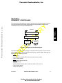
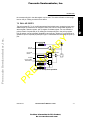
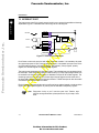
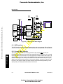
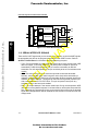
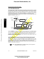
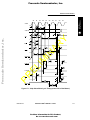
If the SEL bit for a particular pin is cleared, you configure the port pin to have a
special-purpose function. For example, while the port K Bit 0 of the select register is cleared,
this pin is the output master serial peripheral interface TXD signal. In this case, Data to
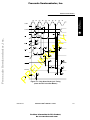
Module signal in Figure 7-1 is connected to the master serial peripheral interface TXD
signal. Since this bit is output-only, the Output Enable from module signal is always asserted
and the Data to module signal is not used. Another example is that the port K Bit 1 can be
used as the master serial peripheral interface RXD input-only signal. In this case, the Output
Enable from module input is negated and the Data from module signal is not used. The Data
to module signal is connected to the master serial peripheral interface RXD input.
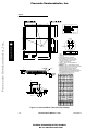
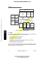
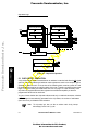
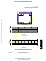
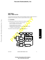
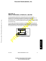
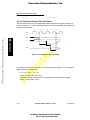
Figure 7-1 illustrates the internal logic of each basic port.
MOTOROLA
MC68328 USER’S MANUAL 12/9/97
For More Information On This Product,
Go to: www.freescale.com
7-1
7
PARALLEL PORTS
Freescale Semiconductor, Inc.