1
SeeGate2
Container Code Recognition
System
System Information
Mar 18, 2009
SeeGate2 System Information
page 2
Table of Contents
1.
PURPOSE & SCOPE ............................................................................... 4
2.
REFERENCED DOCUMENTS ................................................................. 4
3.
OVERVIEW .............................................................................................. 5
4.
5.
6.
3.1.
Product description ............................................................................................................. 5
3.2.
Typical installation at Port gates ....................................................................................... 5
3.3.
SeeGate System advantages................................................................................................ 7
3.4.
SeeGate Installations ........................................................................................................... 8
3.5.
Other Systems in the product line.................................................................................... 11
3.6.
Overview of this document ............................................................................................... 12
ARCHITECTURE ................................................................................... 13
4.1.
Overview of Container ID ................................................................................................ 13
4.2.
Overview of the Architecture ........................................................................................... 14
4.3.
The Image processing DLLs ............................................................................................. 16
4.4.
Display Design ................................................................................................................... 17
4.5.
SeeGate2 Viewer ................................................................................................................ 20
4.6.
SeeTerminal ...................................................................................................................... 21
4.7.
SeeMonitor and SeeService .............................................................................................. 22
4.8.
Computers Configuration................................................................................................. 24
SYSTEM OUTPUTS AND INTERFACES .............................................. 25
5.1.
Event Message ................................................................................................................... 25
5.2.
Output files......................................................................................................................... 26
5.3.
Log Files ............................................................................................................................. 30
5.4.
TOS interface ..................................................................................................................... 31
SUMMARY OF FUNCTIONS ................................................................ 35
6.1.
General Requirements ...................................................................................................... 35
6.2.
GUI (Graphical User Interface) ....................................................................................... 35
SeeGate2 System Information
page 3
6.2.1 SeeGate .................................................................................................................................... 35
6.2.1 SeeGate Viewer ....................................................................................................................... 35
7.
6.3.
Operation Results .............................................................................................................. 36
6.4.
Image Handling ................................................................................................................. 36
6.5.
Installation Mode............................................................................................................... 36
6.6.
Sensor Control ................................................................................................................... 36
6.7.
File ...................................................................................................................................... 37
6.8.
Communication ................................................................................................................. 37
6.9.
Diagnostics ......................................................................................................................... 37
SUPPORT AND MORE INFORMATION ................................................ 38
SeeGate2 System Information
page 4
1.Purpose & Scope
This document provides and overview and technical information on SeeGate2, a
second generation vision-based Container Code Recognition system.
2.Referenced Documents
2.1.1. Documents
2.1.1 SeeGate2 Installation guide [HTS publication]
2.1.2 SeeGate2 User manual guide [HTS publication]
2.1.3 Freight Containers - Coding, Identification and Marking [ISO 6346 1995(E)]
2.1.4 SeeUtilities manual [HTS publication]
2.1.2.Concepts and Shortcuts
• OCR – optical character recognition
• CCR – container code recognition
• ID – Identification
• LPR – license plate recognition
• GUI – graphical user interface
• HTS – Hi-Tech Solutions
• DLL – Dynamic Link Library
• IMO – International Maritime Organization
• SDK - Software Development Kit
• TOS – terminal operating system
SeeGate2 System Information
page 5
3.Overview
3.1.
Product description
SeeGate2 is a stand-alone system that is used to automatically track and read
Shipping Containers identification number together with the license plate of the
carrying Truck. This sophisticated image processing system can be placed at various
port locations: at gates, at the docks, or in any other location that requires fully
automatic identification.
The identified number strings, information and the images are displayed on the
system’s main display, and logged in its local database. This data is transferred over
the TCP/IP network on messages and files, and reported to other Windows
applications on a central server. The information can be added into the Terminal
Operating System (TOS) for further processing.
Each system controls several video cameras and handles them simultaneously while
the truck and containers are in motion. The system uses these multiple cameras in
order to look at various sides of the containers, and provide the container information.
The system also provides damage inspection and exception handling options in the
form of movie clips and optionally in the form of still images. It also captures and
analyzes the Truck license plate. As additional options, the wagon/chassis ID can be
recognized as well.
3.2.
Typical installation at Port gates
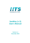
The following illustration highlights the main feature of the system: all the cameras
and illumination units are mounted on a single gantry. This simplifies the installation,
which in the previous generation system (SeeGate1) was constructed on a long
structure.
The system takes multiple images of the top/rear and the left/right sides. The cameras
are mounted on the top (one or two cameras), the left side (2 cameras) and the right
side (2 cameras). The use of dual cameras on the sides enables the system to narrow
down the width of the lane, down to 1.2M from the sides, which is a great advantage
over mono cameras systems.
SeeGate2 System Information
page 6
Figure 3.2: Port gate installation (simplified)
The system also uses 2 LPR cameras (on both sides of the lane) to recognize the
plate. The cameras use different spectrum of illumination (visible and near-IR) for
extended coverage of non-reflective plates. Additional configurations are available
using rear cameras (for wagon ID).
Additionally, the system requires three ground loops to detect the truck and
container, and a pair of IR sensors on the Gantry.
SeeGate2 System Information
page 7
3.3.SeeGate System advantages
The system has the following advantages over existing manual recorded sites:
• fully automatic process (no man-in-the-loop)
• increases the processing of the container/truck traffic at the congested gates
• the system data collects the traffic history (and reports the result to a central
server)
• handles simultaneously container & truck identification
• performs damage inspection and exception handling image and video capture
•
•
•
•
•
•
•
•
•
•
The system has the following advantages over other automated solutions:
simple configuration (single gantry; single PC for the basic features)
covers all types of containers (20,40,20/20feet and combinations)
performs recognition while at motion (the container does not stop)
simple integration into the existing computer resources at the port
has a high recognition rate (has up to 5 views redundancy on each container)
a reliable system, 24 hour operation (backed by system utilities that guarantee the
up time)
fast response (output in seconds)
solid state illumination (lower power consumption; maintenance free)
area-scan imagery (lower illumination requirements; multiple information capture)
typical lane width – 6.4M; minimum width – 4.9M (much smaller than other
systems)
SeeGate2 system has the following additional features over SeeGate1 first generation
system:
• Compact footprint (single arch gantry)
• Color container imagery
• Movie clips (for Damage inspection, security and exception handling)
• Damage inspection still images (optional)
• IMO label detection (optional)
• Additional top view recognition (front and rear)
• Container type/size recognition
SeeGate2 System Information
page 8
3.4.SeeGate Installations
SeeGate systems are leading the number of Worldwide installations. Over hundred
portals are installed worldwide.
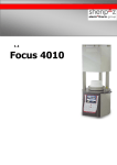
A sample installation of SeeGate2 is shown in the following photo. This site has two
portals, one entrance and one exit. Note that this specific site is covered, but this is
not required for the system.
Photo 3.4.1: SeeGate 2 Installation (Rotterdam, The Netherlands)
SeeGate2 System Information
page 9
Another site is shown below. This site is installed at the edge of a secured entry, and
is constrained to 1.1M view range for the cameras. This tight geometry is only
possible with SeeGate2, using the dual side camera solution.
Photo 3.4.2: SeeGate2 Installation (Rotterdam, The Netherlands)
There are 12 illumination units on 3 sides, which are pulsed solid-state white
illumination units that support the color camera capture with a very low power
consumption. The cameras capture dozens of area-scan images on all sides in
different illumination levels (one of 4: off, low, medium, high) on all 5 views (2 top, 1
rear, 1 left, 1 right).
SeeGate2 System Information
page 10
Another site is shown below. There are 6 portals in this site, and the photo shows one
set of 3 lanes.
There are 10 illumination units on 3 sides, 5 container cameras and 2 LPR cameras.
Photo 3.4.3: SeeGate2 Installation (Rotterdam, The Netherlands)
SeeGate2 System Information
page 11
As a reference, one of the SeeGate1 (first generation) systems installations is shown
in the photo below, where 56 portals were installed in 3 plazas. As seen in this photo,
the system is mounted on long structures.
Photo 3.4.4: SeeGate 1 Installation – APM Pier 400 (LA, California)
3.5.Other Systems in the product line
HTS installs other systems that can integrate with SeeGate systems, and provide
additional recognition results in other locations in the terminal. All such systems
share the same interfaces and can easily integrate with the TOS.
The systems that are currently installed in the terminals are:
• SeeTruck – recognition for LPR only for pedestal lanes or for security gates.
The system automatically matches the event to a portal event and copies the
portals results fields into the event message. Hundreds of such systems are
deployed in terminals.
• SeeCrane – quay crane recognition systems.
• SeeTrain – portal single track rail-side recognition system, installed in the
terminal rail gate or inside the yard.
• SeeRail – multiple tracks fast speed rail-side recognition system, installed
outside of the terminal.
SeeGate2 System Information
page 12
3.6.Overview of this document
This document provides the technical information on SeeGate2 system in the
following sections:
4. Architecture
5. System Outputs
6. Summary of functions
7. Support and more information
SeeGate2 System Information
page 13
4.Architecture
This section describes the architecture of the SeeGate2 system.
4.1.Overview of Container ID
The main purpose of the SeeGate Container Recognition software is to take pictures
of the Containers, extract the alpha numeric digits out from the picture (by image
processing software), verify its correctness (using the Container Code check digit as a
final verification test), and transmit the identification string and optionally the image
files.
An example of a container code ID shown in figure 3.4. Note that this is one of the
several container ID formats that the international standard (ref. #2.2) defines. Other
horizontal and vertical markings are possible as well and are recognized by the
system.
Figure 4.1: Example of container ID
The container ID is composed of several fields, including the following fields:
1. the shipping company (e.g., “UXX”)
2. the equipment category (always “U” for freight containers, "Z" or "C" for chassis)
3. the serial number of the container (e.g., “423697”).
4. the check digit of the first 3 fields (e.g.,”0”)
5. the container country, size/type (e.g.,”SE4310”)
Only the first 3 fields are relevant to the identification of the container, and represent
a unique identification number for each shipping container. In the above case, this ID
is “UXXU 423687”.
SeeGate2 System Information
page 14
The shipping company field ("UXX"in the example) is verified against a predefined list of known companies. Additionally, the second field ("U") is always
verified.
The check digit is used in order to verify the entire 10-fonts identification number.
If the check digit is not identified, only the 10 fonts are compared and reported. If it is
recognized and tested for correctness, it will also be reported (a "0" in the above
case).
The size/type in the ISO code (in the above example,”4310”) is also part of the ID
and is identified and transmitted. The country origin (which is an optional field) is not
covered by the system.
4.2.Overview of the Architecture
The system is based on a stand-alone system that includes the following:
a) Software:
• PC running Windows XP pro (to run the system’s software)
• SeeContainer, SeeCar, SeeSizeType and optionally SeeChassis 32-bit DLLs
(Dynamic Link Libraries, that recognize the Container/license plate/Chassis from
an input image)
• Local database (MS-SQL) to store the results (used by SeeGateViewer to show
the results)
b) Hardware:
•
•
•
•
•
•
•
•
•
5-6 container color cameras (for recognition and inspection)
white illumination solid-state strobe units (for recognition and inspection)
2 camera/illumination units for license plate
1-2 camera/illumination units for optional Chassis/Wagon ID
2 4-video-input frame grabbers (to capture the images in fast real time)
2 IR sensors (on the gantry, to sense the containers)
3 Loop detectors (to sense the truck and chassis)
I/O board and terminal block (for sensor and gate input and output)
TCP/IP link (used with SeeData product – which transmits the result to a server)
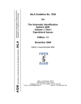
The following simplified illustration shows this configuration.
SeeGate2 System Information
Cameras
page 15
PC
SQL
Frame Grabber
SeeGate2
Event
Message
Identified Container & Truck
5 Sensors
I/O
DLLs
Figure 4.2: SeeGate System simplified configuration
The operation of the system is as follows: when the moving truck and the containers
that it carries enter the detection zone, the sensors (3 loop detectors and 2 IR sensors)
are activated and signal to the program (via the IO card) that the container is present.
The program now starts the recognition process: a sequence of images in different
illumination levels (controlled by the I/O card) are captured according to the container
types and the parameter settings. After this, the images are sent to the SeeContainer,
SeeSizeType and SeeCar DLLs for container recognition and license plate
identification.
After receiving the results and applying certain logic and validation/verification, the
program outputs the combined Container & Truck ID results to the display, and
records the information into a local SQL database. The event information includes a
text result, confidence, file paths to the image and movie clips files, and additional
information.
The system also transmits the recognition event results as a message that is spread
over the network to a central server. The images and movie clips are also copied to
the server. A Client application in the local lane PC or on the central server can listen
to the message and use the data for various tasks, such as loading it to a customer
specific database or load it into the terminal operating system (TOS).
Additional optional functions, such as Damage inspection still images and IMO
label detection, are processed off-line by slave computers which process the captured
images and generate their results in parallel.
SeeGate2 System Information
page 16
4.3.The Image processing DLLs
The system calls the following image processing DLLs that analyze the captured
images of the container and the carrying truck:
• SeeContainer DLL - an ISO 6346 Container Marking recognition software
• SeeCar DLL - a license plate recognition (LPR) package specifically adapted to
the country where the system is installed
• SeeSizeType DLL - a recognition package for recognizing the ISO code
• SeeChassis - a recognition package for the wagon/chassis number (optional on
the SeeGate system)
These 32-bit Windows DLLs perform the following image processing functions:
•
•
•
•
•
Image Enhancement - improves the quality of the captured image
ID numbers finding - locates the marking within the image
Characters detection - locates each of the marking’s characters
Characters identification - identifies each of the detected characters
Validation - compares the resulting string to the standard formats, calculates the
confidence, and verifies check digits (for the container ID only)
The program analyzes the results of the recognition across the series of the captured
images (in different illumination levels and in several capture positions), and
combines them into a final recognition of the Truck and its containers, and
displays/files/sends their results.
SeeGate2 System Information
page 17
4.4.Display Design
4.4.1.Main Display
The main display is a window with a predefined arrangement that is displayed on the
screen and operates like a console. Normally the system does not require a user, and
the main display may be running as a background application. However, it may serve
to monitor the system – useful in the installation and commissioning phases.
The main display shows the status of the I/O in real time, the list of past events, and
also provides a number of options that the user may activate, such as live video
display of each camera, and changing the settings of parameters.
An example of a display is shown in the following illustration, at the middle of a
event of a truck that just entered the portal. The display has several fields:
• Sensor status on the left side ( a graphic representation of the status of the
container sensors and loop detectors; in this example the first 2 loops are on)
• The list of events on the right side (the last line shows that the LPR camera
stopped to capture the new truck at 2 PM)
Figure 4.4.1: Main display example (a truck is just entering the lane)
SeeGate2 System Information
page 18
4.4.2.Parameter Settings Display
An example of the parameter control is shown in the following illustration. The user
can define a series of parameters that control the operation of the system. In the
following display, the Container Left Upper camera parameters are defined. In a child
window that opens up under the “+” sign, the capture sets for this camera can be
defined – and the illumination levels can be selected.
4.4.2: Parameter Settings
SeeGate2 System Information
page 19
4.4.3.Live Video Display
For installation assistance, a special live display can be selected. This display can
show the live video of each camera. The illumination level of each of the illumination
units associated with that camera can be activated.
Photo 4.4.3: Live video display (in this case - the upper left container camera )
For a complete description of the user interface, please refer to the SeeGate2 user
manual.
SeeGate2 System Information
page 20
4.5.SeeGate2 Viewer
SeeGate2 records the events into a local database (Microsoft SQL). A special
viewer (SeeGate View) can be used to view the live events results or search the past
events.
The following sample shows an online view of the still images (the “Picture” tab) or
the movie clips (the “Movie” tab) – on the left side. The information on this event is
seen on the upper right side, and the list of events are displayed on the lower right
side.
Photo 4.5: SeeGate view: A viewer for the on-line and past events
SeeGate2 System Information
page 21
4.6. SeeTerminal
The SeeGate2 system is part of a network, and its results are transmitted to
SeeTerminal, the central server application. The architecture is illustrated in the
following figure. The SeeGate2 lane PC and its optional slave PCs are connected to a
central HTS server, which is also connected to the external systems (such as TOS or
interface programs) by a TCPIP network. SeeTerminal application runs in this server,
collects messages from all the SeeGate2 lane PC systems and optional Slave PCs
(Damage and IMO results), or other Seex systems, and talks with the external systems
using XML. The application also supports a MSMQ interface with other systems.
In addition to the messages, the images from the lane and slave PCs are copied into
the images repository on the server. Note that the source of the images stays in these
PCs as backup. The external systems can read these images over the network.
TOS
Other
subsystems
Interface PC
MSMQ I/F for
other systems
TCP Messages (XML)
HTS Server
Viewer
SQL
SeeTerminal
Images
Repository
TCP
Messages
TCP Messages
Other Seex
.
SeeGate 2
(Lane PCs)
.
SeeDamage/IMO
(Slave PCs)
SeeGate2 System Information
page 22
The SDK (Software Development Kit) is provided in order to support the
development of the client application. It contains VC++ sources of a sample client
application, and a SeeGate2 simulator that is used to test the client application.
4.7.SeeMonitor and SeeService
The SeeGate system has additional networking and operational utilities, that simplify
the operation of multiple units and ensure that the entire site is running smoothly:
• SeeMonitor – this central utility allows to see the status of an array of
SeeGate units, and get histograms and other graphs on each of the lanes and
each of the cameras. This is useful both at the installation time and in the
operation phase.
A sample of 2 displays are shown in the following figures.
• SeeService – this watch-dog utility keeps the SeeGate application running at
all times and optionally updates new versions from a server
• SeeCleaner – this utility performs housekeeping operations in the working
directory
For more details, please refer to the SeeUtilities document (reference #2.1.4).
Figure 4.7.1: SeeMonitor status display (green=OK, yellow=warning, red=error)
SeeGate2 System Information
page 23
Figure 4.7.2: Sample SeeMonitor graph (in this case, top shift of the container ID)
SeeGate2 System Information
page 24
4.8.Computers Configuration
4.8.1.Lane Computer
The lane computer is a desktop/rack-mount PC which is installed in cabinets near the
lanes.
For more details, refer to the installation manual (reference #2.1.1).
4.8.2.Slave Computers
The system can be ordered with the following options:
•
Damage inspection still images (in addition to the movie clips)
•
IMO label detection and classification
For these options, additional slave computers are required in order to support the
computing power required for these operations. The slave computer can be installed
in a remote computer room, near the Server computer (unlike the lane computer that
must be installed close to the lane), using a G-bit network.
The following illustration shows the computer architecture.
TOS
HTS Server computer
Message
SeeGate2
Message
SeeGate2 Lane
“master”
computer
SeeDamage/IMO
Slave computer(s)
Images
capture
d from
Images are shared and
read by the slave systems
Figure 4.8: Computers configuration (slave computers are optional)
Server Room
(Remotely
located)
SeeGate2 System Information
page 25
5.System Outputs and Interfaces
This section details the outputs and interfaces of the system:
5.1 Messages
5.2 Image and video Files
5.3 Log Files
5.4 TOS interface
5.1.Event Message
For each event the system generates a message that is broadcasted to the server. This
message contains information on the event (the following are the major items that are
contained in the message structure):
• Lane number
• Data and time
• Event number
• For each container:
o Container string (single dot for unrecognized digit, or dots if
unrecognized)
o Confidence
o Image path
o Size/type (ISO code)
• Truck plate string
o Registration number
o Confidence
o Image path
The message is reported to the SeeTerminal application on the central server. There,
it transmits the results to either an external PC (using XML interface) or to a client
application. These applications are developed by the client or 3rd party, and can use
the information in order to feed the TOS, archive the results, complement the data
(such as compare to a database), display the results, or for other uses.
SeeGate2 System Information
page 26
5.2.Output files
5.2.1.Image files
The system saves for each event the best container and truck camera image. It can
also save an image for each camera. The image may be selected to be a jpg image (5
different levels of compression can be selected), or a larger bitmap file. For the
highest quality jpgs the size is about 50KB.
The images are stored in daily local directories (as default settings), and can be copied
to the central server by the SeeData utility (to a lane-specific daily folder).
An example of the left side is shown below:
Figure 5.2.1: example of image
SeeGate2 System Information
page 27
5.2.2.Video Clips Files
The system produces 4 video clips on each event:
Top
Back
Left
Right
Each movie clip is generated from a series of images that each camera collects.
The size of each movie clip depends on the defined read rate (default is 3 per
second), and the length of the event. Typically, the left and right sides are longer
(about 2-4MB at average). The top clip is smaller (about 1.5MB) and the back is the
smallest (0.5-1.0 MB).
For the left and right sides, the entire length of the container(s) is shown, including
the truck. Theses clips start from the upper camera, then show the lower camera. The
truck portion is useful for security reasons, since the driver is seen in 4 different
cameras and several angles (during the motion of the truck). The container part is
useful for damage inspection, and defects (like holes) are seen in several instances.
Each movie clip can be stopped, and could be zoomed or saved and printed. This
allows a careful inspection of the event, an advantage over line-scan systems. The
movie clips are standard MPEG4 AVI files, and could be played on standard
Windows media players.
The following figure shows a sample section of such movie clip. It shows 2 parts in
the movie stream of the right clip, where the driver is seen at the right clip.
Figure 5.2.2: example of movie clip (2 frames in the video stream)
SeeGate2 System Information
page 28
5.2.3.Damage Inspection Still Images (option)
A system option is to generate still images from the collected images. The system
automatically stitches the images together, and generates a broad (and flat) view of
the container, in 4 views (left, right, top, rear). Each jpg image is about 5M pixels,
and the size is about 500KB per file (except for a smaller rear view).
The following photo is an example of the stitched image of a side container. It is the
result of combining dozens of intermediate images of both side cameras.
A top image example is seen below:
This option requires a slave computer. This computer accesses the saved images,
and runs off-line in order to generate the images. It takes about 1 minute to generate
each event set, and the images are saved as jpg images.
SeeGate2 System Information
page 29
5.2.4.IMO label classification (option)
SeeGate2 has an option to classify IMO (Hazmat) labels. It recognizes the dangerousgoods decal from 3 sides (left, right, rear) and outputs the class and optional sub-class
together with the detected Icon.
This option is executed in a slave computer.
SeeGate2 System Information
page 30
5.3.Log Files
5.3.1.Windows Event Log
The system writes events to the Windows applications event log upon each new
execution or whenever the system detects a problem, such as when the application is
closed. There are several event types (information, warnings and errors). This event
log is used by SeeMonitor tool to display the status of all lanes, and to report a fatal
error (“red”) to an external system.
5.3.2.Debug Information Log files
The system writes debug information into text files in its working directory. These
files are used by SeeMonitor tool in order to display historic graphs which are useful
for fine-tuning the system.
SeeGate2 System Information
page 31
5.4.TOS interface
5.4.1.Methods
The system can be integrated with terminal operating systems (TOS), which use the
recognition results for archiving, display, checking the container delivery or dispatch,
automating the processes, tracking the traffic or any other tasks.
The following integration options exist for such interface:
• Intercept the event message, write the results into the TOS. For this integration
option a SDK is supplied in order to assist this integration.
• Load the message into a database, and access the database in order to integrate
with the TOS or other automated processes. For this integration method a third
party database is available (presented in the following paragraph).
SeeGate2 System Information
page 32
5.4.2.Example of TOS interface
This paragraph describes a sample application: an example of a TOS interface in a
Rotterdam terminal. It is developed by “IT Partner” (NL), based on the database that
was developed by “Dalosy” (NL), and is a retrofit to an existing operation, which is
based on “Cosmos”.
I n this case, the event message from SeeGate2 is recorded into a central SQL
database on the server. Additional data fields are optionally added to the database in
addition to the raw recognition results. Then, the data is extracted and added into the
TOS system or displayed on the operators display.
The following figure shows the license plate, which is the key for accessing the
event information. The operator enters this key in the driver assistance office, and
then the event information is automatically retrieved from the database.
Figure 5.4.2a: Truck plate is the key for retrieving the record
The event information is then displayed, as shown in the figure. The operator may
then either check the still images (under the “pictures” tab), or play the video clips (4
sides, under the “video” tab).
SeeGate2 System Information
page 33
The following figure shows the movie clips selection and control display. On the
bottom of the display the operator may select one of the 4 clips, and then it is
displayed in the center. The movie clip plays the recorded event, and both the truck
and the containers are seen driving thru the gate.
Figure 5.4.2b: Movie clips that are retrieved for the selected event
On each movie clip the operator may change the display speed, stop the stream and
slide the view to any frame, and optionally save the frame into an additional still
image which will be added to the still images that were captured.
The information is also collected in the visit record, as shown below. This record
includes both the recognition results, driver information, and job details.
SeeGate2 System Information
page 34
Figure 5.4.2c: Visit information – which includes the recognition information
Similar integrations may use the recognition information and files in order to
automate and enhance the terminal operation. HTS provides an SDK, utilities and
support in order to implement such integrations in retrofits and new terminal
installations.
SeeGate2 System Information
page 35
6.Summary of Functions
This section lists the functions of the system. For more information, please refer to the
installation manual or the application on-line help.
Note that Hi-Tech Solutions may change these functions on future system releases,
and additional functions may be tailored for specific customer requirements.
6.1.General Requirements
A. Intended system use: stand-alone Container ID and Truck
Number (optional Chassis/Wagon ID Number) automatic identification
system.
B.
Single Lane - supports a single container lane.
C.
Container Types - All standard cases:
40 feet, 20 feet front, 20 feet rear, double 20 feet, 45 feet.
D.
Moving containers - the system will handle the recognition
while the container is moving, from 5KM/H up to 30KM/H.
E.
Write results into a local database (MS-SQL), which is used by
SeeGateViewer application to show on-line and past results.
F.
Configurations:
•
Base SeeGate2 (LPR, CCR, size/type, movie clips)
•
Option A: Damage inspection still images
•
Option B: IMO label detection
•
Option C: Chassis (USA) or wagon recognition
6.2.GUI (Graphical User Interface)
6.2.1 SeeGate
A. Sensors status - on/off status for 3 loops and IR sensors
B.
System status events list
C.
Camera View Display- cameras live video display (see: image handling)
D.
On-line help.
6.2.1 SeeGate Viewer
A. Event Log - list of event results (one row for each event)
SeeGate2 System Information
page 36
B. Recognition results text information
C. Recognition images/movies display
D. Images/Movies display control panel
E. History search and control options
F. On-line help.
G. Save the list as text file.
6.3.Operation Results
A. Container Identification
B.
License plate recognition
C.
Optional chassis/wagon recognition
D.
Size/Type recognition
E.
Damage/Exception handling movie clips (x4 per event)
F.
(Optional) Damage stitched still images (x4 per event)
G.
(Optional) IMO label detection and classification
6.4.Image Handling
A. Display camera (live video; color for container cameras and B/W for LPR
cameras)
B.
Configuration of the camera settings
C.
Configure # of captures per application
6.5.Installation Mode
A. Live Video - select one of the cameras
B.
Illumination control – select any illumination level
6.6.Sensor Control
A.
Sensor types : 3 loops detectors; 2 IR sensors
B.
Display Status of sensor
C.
Sensor Configuration:
•
NC/NO (normally-connected or normally-open state)
•
Pin # on Parallel connector
•
Active Rise or Fall
SeeGate2 System Information
6.7. File
A. Images File Save (bmp or 5 levels of jpg)
B.
Movie clips settings (enable; capture rate)
C.
Daily/weekly/monthly or single directory
D. SeeCleaner housekeeping support
6.8.Communication
A.
Central server IP definition. (Works in conjunction with
SeeData-Center that is installed on a central server)
B.
Enable/Disable.
6.9.Diagnostics
A. SeeMonitor support (displays status and historic reports)
B.
Writes information/warning/error into Windows event log
C.
Reports on low recognition (warnings and errors)
D.
Supports SeeService (watchdog and automatic software
upgrades)
page 37
SeeGate2 System Information
page 38
7.Support and more Information
You can contact us for more information and assistance at:
Hi-Tech Solutions
POBox #133 Migdal-Haemek Israel 10500
Internet
http://www.htsol.com
Email
[email protected]
Israel.....Tel (+972) 46 440 440
Visit our Home page (http://www.htsol.com) and download demo recognition
applications.
You can also view sample installations in the photo gallery, or download more
documentation.
You can also download a simulation of the SeeGate2 system and a sample Client
application.