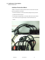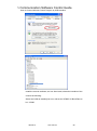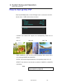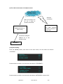
1
VENUS X1 User Manual Manual #: RGB-RD-UM-VENUS X1 E001 Revision: V1.2 VENUS X1 User Manual 1 VENUS X1·User Manual Thank you for choosing our products! In order to allow you to learn how to use the video processor quickly, we bring you the detailed user’s guide. You can read the introduction and directions before using the video processor, please read all the information we provide carefully to use our products correctly. Copyright ©2015 All rights reserved by RGBLINK. This document is done by Xiamen RGBlink Science & Technology Co.,Ltd independently. No part may be copied, reproduced or translated without permission. Notice RGBlink provides this manual ―as is‖ without warranty of any kind, either expressed or implied, including but not limited to the implied warranties or merchantability and fitness for a particular purpose. RGBlink may make improvements and/or changes to the product(s) and/or the program(s) described in this publication at any time without notice. This publication could contain technical inaccuracies or typographical errors. Changes are periodically made to the information in this publication; these changes are incorporated in new editions of this publication. Federal Communications Commission (FCC) Statement This equipment has been tested and found to comply with the limits for a class A digital device, pursuant to Part 15 of the FCC rules. These limits are designed to provide reasonable protection against harmful interference when the equipment is operated in a commercial environment. This equipment generates, uses, and can radiate radio frequency energy and, if not installed and used in accordance with the instruction manual, may cause harmful interference to radio communications. Operation of this equipment in a residential area may cause harmful interference, in which case the user will be responsible for correcting any interference. VENUS X1 User Manual 2 Guarantee and Compensation RGBlink provides a guarantee relating to perfect manufacturing as part of the legally stipulated terms of guarantee. On receipt, the purchaser must immediately inspect all delivered goods for damage incurred during transport, as well as for material and manufacturing faults. RGBlink must be informed immediately in writing of any complains. The period of guarantee begins on the date of transfer of risks, in the case of special systems and software on the date of commissioning, at latest 30 days after the transfer of risks. In the event of justified notice of compliant, RGBlink can repair the fault or provide a replacement at its own discretion within an appropriate period. If this measure proves to be impossible or unsuccessful, the purchaser can demand a reduction in the purchase price or cancellation of the contract. All other claims, in particular those relating to compensation for direct or indirect damage, and also damage attributed to the operation of software as well as to other service provided by RGBlink, being a component of the system or independent service, will be deemed invalid provided the damage is not proven to be attributed to the absence of properties guaranteed in writing or due to the intent or gross negligence or part of RGBlink. If the purchaser or a third party carries out modifications or repairs on goods delivered by RGBlink, or if the goods are handled incorrectly, in particular if the systems are commissioned operated incorrectly or if, after the transfer of risks, the goods are subject to influences not agreed upon in the contract, all guarantee claims of the purchaser will be rendered invalid. Not included in the guarantee coverage are system failures which are attributed to programs or special electronic circuitry provided by the purchaser, e.g. interfaces. Normal wear as well as normal maintenance are not subject to the guarantee provided by RGBlink either. The environmental conditions as well as the servicing and maintenance regulations specified in this manual must be complied with by the customer. Trademarks Brand and product names mentioned in this manual may be trademarks, registered trademarks or copyrights of their respective holders. All brand and product names mentioned in this manual serve as comments or examples and are not to be understood as advertising for the products or their manufactures. VENUS X1 User Manual 3 Company Address Xiamen RGBlink Science & Technology Co., Ltd. Headquarter: S603~604 Weiye Building Torch Hi-Tech Industrial Development Zone Xiamen, Fujian Province, P.R.C Shenzhen office: Floor 11, A1 Building, Baiwang R&D Building, Shahe West Road, Xili Town, Nanshan District, Shenzhen, Guangdong Province, P.R.C Beijing office: No. 2702, Sino-Light Building Tower B, Wang-Jing East Road, Chaoyang District, Beijing, P.R.C Shanghai office: East Building F2, No. 88 Qinjiang Road, Shanghai, P.R.C VENUS X1 Tel: +86-592-5771197 Fax: +86-592-5771202 Customer Hotline: 4008-592-315 Websites: ~ http://www.rgblink.com ~ http://www.rgblink.cn E-mail: [email protected] User Manual 4 Operators Safety Summary The general safety information in this summary is for operating personnel. Do Not Remove Covers or Panels There are no user-serviceable parts within the unit. Removal of the top cover will expose dangerous voltages. To avoid personal injury, do not remove the top cover. Do not operate the unit without the cover installed. Power Source This product is intended to operate from a power source that will not apply more than 230 volts rms between the supply conductors or between both supply conductor and ground. A protective ground connection by way of grounding conductor in the power cord is essential for safe operation. Grounding the Product This product is grounded through the grounding conductor of the power cord. To avoid electrical shock, plug the power cord into a properly wired receptacle before connecting to the product input or output terminals. A protective-ground connection by way of the grounding conductor in the power cord is essential for safe operation. Use the Proper Power Cord Use only the power cord and connector specified for your product. Use only a power cord that is in good condition. Refer cord and connector changes to qualified service personnel. Use the Proper Fuse To avoid fire hazard, use only the fuse having identical type, voltage rating, and current rating characteristics. Refer fuse replacement to qualified service personnel. Do Not Operate in Explosive Atmospheres To avoid explosion, do not operate this product in an explosive atmosphere. VENUS X1 User Manual 5 Terms in This Manual and Equipment Marking WARNING Highlights an operating procedure, practice, condition, statement, etc, which, if not strictly observed, could result in injury or death of personnel. Note Highlights an essential operating procedure, condition or statement. CAUTION The exclamation point within an equilateral triangle is intended to alert the user to the presence of important operating and maintenance (servicing) instructions in the literature accompanying the appliance. VENUS X1 User Manual 6 Change History The table below lists the changes to the Video Processor User Manual. Format Time V1.0 2015-05-18 V1.1 V1.2 Description Principal 0000# Release Vira 2015-08-06 0001# 1. Update the front and back panel. 2. Update the menu tree. 3. Update the windows control program. 4. Update the common questions and solutions. Vira 2015-10-29 0002# 1. Update the front and back panel. 2. Update the menu tree. 3. Update the product picture. 4. Update the dimensions drawing 5. Update the specification. 6. Update ―Optional Module Installation and Replacement Instruction‖. 7. Add ―VENUS X1 Connect APP Control Operation‖. Vira VENUS X1 ECO# User Manual 7 CONTENT CONTENT ............................................................................................. 8 1. Introduction ................................................................................... 15 Chapter Structure ........................................................................................ 16 How to Use This Manual .............................................................................. 17 Terms and Definitions .................................................................................. 18 System Overview ......................................................................................... 23 Application Questions.................................................................................. 24 2. Hardware Orientation .................................................................... 25 In This Chapter ............................................................................................ 25 VENUS X1 Back Panel................................................................................... 26 CONT Interface...................................................................................................... 26 4: DIP Switch ......................................................................................................... 26 5: 10/100M UDP Interface .................................................................................... 26 6: USB Interface .................................................................................................... 26 7: RS232 Interface ................................................................................................. 27 INPUT Interface ..................................................................................................... 27 10: HDMI Input ..................................................................................................... 27 11: CVBS Input ...................................................................................................... 27 12: VGA Input ........................................................................................................ 27 13: DVI Input ......................................................................................................... 27 OUTPUT Interface ................................................................................................. 27 VENUS X1 User Manual 8 8.17: Sending Card Interface ................................................................................ 27 14: DVI1/DVI LOOP Output ................................................................................... 27 15: DVI2 Output .................................................................................................... 28 16: VGA Output..................................................................................................... 28 Optional Module ................................................................................................... 28 1. 2. 3: Optional Module Slots .............................................................................. 28 Illuminated Power Switch and Power ................................................................... 30 9. 18: Power Interface and Illuminated Power Switch ......................................... 30 Interface Protection Block .................................................................................... 31 VENUS X1 Front Panel ................................................................................. 32 OLED Panel ............................................................................................................ 34 Menu Button ......................................................................................................... 34 Signal Buttons ....................................................................................................... 34 Function ................................................................................................................ 35 3. Hardware Installation ..................................................................... 39 In This Chapter ............................................................................................ 39 Safety Precautions ....................................................................................... 40 Unpacking and Inspection ........................................................................... 40 Site Preparation........................................................................................... 40 4. Menu Orientation .......................................................................... 41 In This Chapter ............................................................................................ 41 MENU .......................................................................................................... 42 VENUS X1 User Manual 9 INPUT .................................................................................................................... 43 OUTPUT................................................................................................................. 45 PICTURE ................................................................................................................ 47 SPLIT ...................................................................................................................... 51 TRANSITION .......................................................................................................... 52 SCALE .................................................................................................................... 54 SAVE SETUP ........................................................................................................... 55 SYSTEM ................................................................................................................. 56 LANGUAGE ............................................................................................................ 57 FACTORY RESET ..................................................................................................... 58 QUICK MENU ............................................................................................... 59 SPECIAL EFFECTS SWITCHING ...................................................................... 59 SAVE FUNCTION .......................................................................................... 61 LOAD FUNCTION .......................................................................................... 62 PIP FUNCTION ............................................................................................. 62 SPLIT FUNCTION .......................................................................................... 63 SCALE FUNCTION ......................................................................................... 64 5. Communication Software Guideline ............................................... 65 In This Chapter ............................................................................................ 65 Software Installation.................................................................................... 66 Software Operation ..................................................................................... 70 Connection ............................................................................................................ 70 VENUS X1 User Manual 10 Use ........................................................................................................................ 71 File Toolbar ........................................................................................................... 71 Communication Toolbar ....................................................................................... 72 Device Toolbar ...................................................................................................... 72 Output Resolution Toolbar ................................................................................... 74 Display Mode Toolbar ........................................................................................... 74 Layout Toolbar ...................................................................................................... 74 Aspect Ratio Toolbar ............................................................................................. 74 Signal Input Toolbar .............................................................................................. 75 Screen Parameter Toolbar .................................................................................... 75 Image Toolbar ....................................................................................................... 76 Display Toolbar...................................................................................................... 76 Output Toolbar...................................................................................................... 76 Images Display Toolbar ......................................................................................... 77 User Mode Toolbar ............................................................................................... 77 Log Toolbar............................................................................................................ 77 Information Toolbar .............................................................................................. 78 Control .................................................................................................................. 78 Language ............................................................................................................... 82 Admin .................................................................................................................... 82 Help ....................................................................................................................... 83 How to Connect Window Control Program by RS232 Interface ................... 84 VENUS X1 User Manual 11 How to Connect Windows Control Program by USB Interface ..................... 87 How to Connect Windows Control Program by LAN Interface ..................... 91 6. System Setup and Operations......................................................... 94 In This Chapter ............................................................................................ 94 Interface and Input Signal Option ................................................................ 95 How to Realize Single Image Switching ........................................................ 97 How to Set up the PIP .................................................................................. 98 How to Set up the SPLIT .............................................................................. 99 How to Set the Size and Position of the Single Image ................................ 101 How to Choose and Custom Output Resolution......................................... 102 How to Realize the Screen Size Setting ...................................................... 104 How to Zoom the Image ............................................................................ 106 How to Realize the Text Overlay Setting ..................................................... 107 How to User Define the BLACK Key............................................................ 109 How to User Define the SCALE Key ............................................................ 112 How to Realize the TAKE Mode .................................................................. 114 How to Realize the Special Effects Switching ............................................. 115 How to Realize the Audio Setting............................................................... 116 How to Use Black Out ................................................................................ 117 How to Realize LAN Remote Control Settings ............................................ 118 How to Save the Parameter ....................................................................... 121 How to Load the Saved Parameter ............................................................. 122 VENUS X1 User Manual 12 7. Common Questions and Solutions .................................................123 In This Chapter .......................................................................................... 123 Input Jitter for I System of HDMI ............................................................... 124 Change the Input as P System ............................................................................ 124 Connect the HDMI Signal to the EXT_HDMI Input ............................................. 124 DVI Quick Split Operation .......................................................................... 124 It Needs Signal Distributor if Split by DVI Port ................................................... 124 Split by the HDMI Loop Out Port of EXT_9 ......................................................... 124 Quick Split ........................................................................................................... 124 There is Flash Point when Output to the LED Screen ................................. 125 Change the DVI Cable ......................................................................................... 125 Change the DVI Output Port ............................................................................... 125 APP Software cannot Properly Connected in Mobile Phone or Tablet Computer .................................................................................................. 126 Confirm if Open the Ethernet Function .............................................................. 126 Confirm if IP Conflict for Mobile Phone, Wireless Router and Device ............... 126 VGA Input Offset or cannot be Full Size Shown .......................................... 126 Set Auto Adjust for VGA Input ............................................................................ 126 HDMI, DVI Input Offset or cannot be Full Size Shown ................................ 127 Manual Adjust the HDMI, DVI and EXT HDMI, EXT DVI ...................................... 127 Software Upgrade Failed ........................................................................... 127 Can’t Open the Device ........................................................................................ 127 VENUS X1 User Manual 13 Failed when Upgrade Less than 100% ................................................................ 127 A. Specification .................................................................................128 B. Contact Information ......................................................................135 C. Software Upgrade .........................................................................136 D. Optional Module Installation and .................................................138 Replacement Instruction ...................................................................138 E. VENUS X1 Connect APP Control Operation ....................................144 VENUS X1 User Manual 14 1. Introduction This chapter is designed to introduce you to the VENUS X1 User Manual. Areas to be covered are: Chapter Structure How to Use This Manual Terms and Definitions System Overview Application Questions VENUS X1 User Manual 15 1. Introduction Chapter Structure Chapter Structure The following chapters provide instructions for all aspects of VENUS X1 operations. Chapter 1 Introduction Chapter 2 Hardware Orientation Chapter 3 Hardware Installation Chapter 4 Menu Orientation Chapter 5 Communication Software Guideline Chapter 6 System Setup and Operations Chapter 7 Common Questions and Solutions Appendix A Specification Appendix B Contact Information Appendix C Software Upgrade Appendix D Optional Module Installation and Replacement Instruction Appendix E VENUS X1 Connect APP Control Operation VENUS X1 User Manual 16 1. Introduction How to Use This Manual How to Use This Manual Following are important tips for streamlining your use of this User Manual in its electronic ―PDF‖ form. Navigating Use Acrobat Reader’s ―bookmarks‖ to navigate to the desired location. All chapter files have the same bookmark structure for instant navigation to any section. Please note: Extensive hyperlinks are provided within the chapters. Use Acrobat’s ―Go to Previous View‖ and ―Return to next View‖ buttons to trace your complete navigational path. Use the ―Previous Page‖ and ―Next Page‖ buttons to go to the previous or next page within a file. Use Acrobat’s extensive search capabilities, such as the ―Find‖ tool and ―Search Index‖ tool to perform comprehensive searches as required. Table of Contents and Index Use the Table of Contents bookmarks to navigate a desired topic. Click any item to instantly jump to that section of the guide. You can also use the Index to jump to specific topics within a chapter. Each page number in the Index is a hyperlink. General Operations To ensure trouble-free operation, please follow all procedures as listed below: For detailed installation instructions, refer to chapter 3 ―Hardware Installation‖ on page 39. For communication software control guide, refer to Chapter 5, ―Communication Software Control Guide‖ on page 65. For system setup and operations, refer to Chapter 6, ―System Setup and Operations‖ on page 94. Should you have any questions regarding the installation or operation of VENUS X1, please consult with the factory. Refer to Appendix B, ―Contact information‖ on page 135. VENUS X1 User Manual 17 1. Introduction Terms and Definitions Terms and Definitions The following terms and definitions are used throughout this guide. “Aspect ratio”: The relationship of the horizontal dimension to the vertical dimension of an image. In viewing screens, standard TV is 4:3, or 1.33:1; HDTV is 16:9, or 1.78:1. Sometimes the ―:1‖ is implicit, making TV = 1.33 and HDTV = 1.78. “AV”: Audio visual, or audio video. “Baudrate”:Named of J.M.E. Baudot, the inventor of the Baudot telegraph code. The number of the electrical oscillations per second, called baud rate. Related to, but not the same as, transfer rate in bits per second (bps). “Blackburst”: The video waveform without the video elements. It includes the vertical sync, horizontal sync, and the chroma burst information. Blackburst is used to synchronize video equipment to align the video output. One signal is normally used to set up an entire video system or facility. Sometimes it is called House sync. “BNC”: Bayonet Neill-Concelman. A cable connector used extensively in television and named for its inventors. A cylindrical bayonet connector that operates with a twist-locking motion. To make the connection, align the two curved grooves in the collar of the male connector with the two projections on the outside of the female collar, push, and twist. This allows the connector to lock into place without tools. “Brightness”: Usually refers to the amount or intensity of video light produced on a screen without regard to color. Sometimes called ―black level. ―CAT 5‖: Category 5. Describes the network cabling standard that consists of four unshielded twisted pairs of copper wire terminated by RJ-45 connectors. CAT 5 cabling supports data rates up to 100 Mbps. CAT 5 is based on the EIA/TIA 568 Commercial Building Telecommunications Wiring Standard. “Color bars”: A standard test pattern of several basic colors (white, yellow, cyan, green, magenta, red, blue, and black) as a reference for system alignment and testing. In NTSC video, the most commonly used color bars are the SMPTE standard color bars. In PAL video, the most commonly used color bars are eight full field bars. In the computer, the most commonly used color bars are two rows of reversed color bars. “Color burst”: In color TV systems, a burst of subcarrier frequency located on the back porch of the composite video signal. This serves as a color synchronizing signal to establish a frequency and phase reference for the chroma signal. Color burst is 3.58 MHz for NTSC and VENUS X1 User Manual 18 1. Introduction Terms and Definitions 4.43 MHz for PAL. “Color temperature”: The color quality, expressed in degrees Kelvin(K), of a light source. The higher the color temperature, the bluer the light. The lower the temperature, the redder the light. Benchmark color temperature for the A/V industry include 5000°K, 6500°K, and 9000°K. “Contrast ratio”: The radio of the high light output level divided by the low light output level. In theory, the contrast radio of the television system should be at least 100:1, if not 300:1. In reality, there are several limitations. In the CRT, light from adjacent elements contaminate the area of each element. Room ambient light will contaminate the light emitted from the CRT. Well-controlled viewing conditions should yield a practical contrast ratio of 30:1 to 50:1. “DVI”: Digital Visual Interface. The digital video connectivity standard that was developed by DDWG (Digital Display Work Group). This connection standard offers two different connectors: one with 24 pins that handles digital video signals only, and one with 29 pins that handles both digital and analog video. “EDID”: Extended Display Identification Data – EDID is a data structure used to communicate video display information, including native resolution and vertical interval refresh rate requirements, to a source device. The source device will then output the optimal video format for the display based on the provided EDID data, ensuring proper video image quality. This communication takes place over the DDC – Display Data Channel. “Ethernet”: A Local Area Network (LAN) standard officially known as IEEE 802.3. Ethernet and other LAN technologies are used for interconnecting computers, printers, workstations, terminals, servers, etc. within the same building or campus. Ethernet operates over twisted pair and over coaxial cable at speeds starting at 10Mbps. For LAN interconnectivity, Ethernet is physical link and data link protocol reflecting the two lowest layers of the OSI Reference Model. “Frame”: In interlaced video, a frame is one complete image. A video frame is made up of two fields, or two sets of interlaced lines. In a film, a frame is one still image of a series that makes up a motion image. “Gamma”: The light output of a CRT is not linear with respect to the voltage input. The difference between what you should have and what is actually output is known as gamma. “HDMI” - High – Definition Multimedia Interface: An interface used primarily in consumer electronics for the transmission of uncompressed high definition video, up to 8 channels of audio, and control signals, over a single cable. HDMI is the de facto standard for HDTV displays, Blu-ray Disc players, and other HDTV electronics. VENUS X1 User Manual 19 1. Introduction Terms and Definitions Introduced in 2003, the HDMI specification has gone through several revisions. “HDSDI”: The high-definition version of SDI specified in SMPTE-292M. This signal standard transmits audio and video with 10 bit depth and 4:2:2 color quantization over a single coaxial cable with a data rate of 1.485 Gbit/second. Multiple video resolutions exists including progressive 1280x720 and interlaced 1920x1080 resolution. Up to 32 audio signals are carried in the ancillary data. “JPEG” (Joint photographic Expects Group): Commonly used method of lossy compression for photographic images using a discreet cosine transfer function. The degree of compression can be adjusted, allowing a selectable tradeoff between storage size and image quality. JPEG typically achieves 10:1 compression with little perceptible loss in image quality. Produces blocking artifacts. “MPEG”: Motion image Expect Group. A standard committee under the auspices of the International Standards Organization working on algorithm standards that allow digital compression, storage and transmission of moving image information such as motion video, CD-quality audio, and control data at CD-ROM bandwidth. The MPEG algorithm provides inter-frame compression of video images and can have an effective compression rate of 100:1 to 200:1. “NTSC”: The color video standard used in North America and some other parts of the world created by the National Television Standards Committee in the 1950s. A color signal must be compatible with black-and-white TV sets. NTSC utilizes an interlaced video signals, 525 lines of resolution with a refresh rate of 60 fields per second (60 Hz). Each frame is comprised of two fields of 262.5 lines each, running at an effective rate of 30 frames per second. “PAL”: Phase Alternate Line. A television standard in which the phase of the color carrier is alternated from line to line. It takes four full images (8 fields) for the color-to-horizontal phase relationship to return to the reference point. This alternation helps cancel out phase errors. For this reason, the hue control is not needed on a PAL TV set. PAL, in many transmission forms, is widely used in Western Europe, Australia, Africa, the Middle East, and Micronesia. PAL uses 625-line, 50-filed (25 fps) composite color transmission system. “Operator”: Refers to the person who uses the system. “PIP”: image-in-image. A small image within a larger image created by scaling down one of the images to make it smaller. Each image requires a separate video source such as a camera, VCR, or computer. Other forms of PIP displays include image-by-image (PBP) and image-with-image (PWP), which are commonly used with 16:9 aspect display devices. PBP and PWP image formats require a separate VENUS X1 User Manual 20 1. Introduction Terms and Definitions scaler for each video window. “Polarity”: The positive and negative orientation of a signal. Polarity usually refers to the direction or a level with respect to a reference (e.g. positive sync polarity means that sync occurs when the signal is going in the positive direction). “RJ-45”: Registered Jack-45. A connector similar to a telephone connector that holds up to eight wires, used for connecting Ethernet devices. ―RS-232”: An Electronic Industries Association (EIA) serial digital interface standard specifying the characteristics of the communication path between two devices using either DB-9 or DB-25 connectors. This standard is used for relatively short-range communication and does not specify balanced control lines. RS-232 is a serial control standard with a set number of conductors, data rate, word length, and type of connector to be used. The standard specifies component connection standards with regard to the computer interface. It is also called RS-232-C, which is the third version of the RS-232 standard, and is functionally identical to the CCITT V.24 standard. “Saturation”: Chroma, chroma gain. The intensity of the color, or the extent to which a given color in any image is free from white. The less white in a color, the truer the color or the greater its saturation. On a display device, the color control adjusts the saturation. Not to be confused with the brightness, saturation is the amount of pigment in a color, and not the intensity. Low saturation is like adding white to the color. For example, a low-saturated red looks pink. “Scaling”: A conversion of a video or computer graphic signal from a starting resolution to a new resolution. Scaling from one resolution to another is typically done to optimize the signal for input to an image processor, transmission path or to improve its quality when presented on a particular display. “SDI”: Serial Digital Interface. The standard based on a 270 Mbps transfer rate. This is a 10-bit, scrambled, polarity independent interface with common scrambling for both component ITU-R 601 and composite digital video and four channels of (embedded) digital audio. “Seamless Switching”: A feature found on many video switchers. This feature causes the switcher to wait until the vertical interval to switch. This avoid a glitch (temporary scrambling) which normally is seen when switching between sources. “SMPTE”: Society of Motion image and Television Engineers. A global organization, based in the United States, that sets standards for baseband visual communications. This includes film as well as video and television standards. “TCP/IP”: Transmission Control Protocol/Internet Protocol. The VENUS X1 User Manual 21 1. Introduction Terms and Definitions communication protocol of the Internet. Computers and devices with direct access to the Internet are provided with a copy of the TCP/IP program to allow them to send and receive information in an understandable form. “USB”: Universal Serial Bus. USB was developed by seven PC and telecom industry leaders (Compaq, DEC, IBM, Intel, Microsoft, NEC, and Northern Telecom). The goal was easy plug-and-play expansion outside the box, requiring no additional circuit cards. Up to 127 external computer devices may be added through a USB hub, which may be conveniently located in a keyboard or monitor. USB devices can be attached or detached without removing computer power. The number of devices being designed for USB continues to grow, from keyboards, mice, and printers to scanners, digital cameras, and ZIP drives. “VESA”: Video Electronics Standards Association. A nonprofit number organization dedicated to facilitating and promoting personal computer graphics through improved standards for the benefit of the end-user. www.vesa.org “VGA”: Video Graphics Array. Introduced by IBM in 1987, VGA is an analog signal with TTL level separate horizontal and vertical sync. The video outputs to a 15-pin HD connector and has a horizontal scan frequency of 31.5 kHz and vertical frequency of 70 Hz (Mode 1, 2) and 60 Hz (Mode 3). The signal is non-interlaced in modes 1, 2, and 3 and interlaced when using the 8514/A card (35.5 kHz, 86 Hz) in mode 4. It has a pixel by line resolution of 640×480 with a color palette of 16 bits and 256,000 colors. “YPbPr”: Used to describe the color space for progressive-scan (non-interlaced) component video. VENUS X1 User Manual 22 1. Introduction System Overview System Overview VENUS X1 is a multiple outputs video processor that accepts a wide variety of video signals, including DVI, VGA, HDMI, CVBS, DP, SDI (SD/HD/3G compatible) and USB. VENUS X1 combines truly seamless, fade in fade out, glitch-free switching with advanced scaling technologies to meet the requirements of high quality, high resolution video presentations. VENUS X1 also launches the latest, user defined image size and coordinate, dual image processing, multiple cascade mapping, different user configurations and controlling, key in and out and other advanced functions for high-end show. VENUS X1 supports EDID editing for VGA, DVI, HDMI input ports and read EDID for output ports, support EDID modify by windows control program. PC modified EDID, users can edit the EDID of input port according to the resolution of outputs to achieve the optimal input resolution. VENUS X1 also supports local front panel operation, remote widows based software control by RS232, USB, Ethernet, and WIFI control. In addition, VENUS X1 is based on replaceable input optional modules structure, with different modules, you can reach more possibility and application range. VENUS X1 User Manual 23 1. Introduction Application Question Application Questions RGBlink offers solutions to demanding technical problems. Any application questions, or required further information, please contact with our Customer Support Engineers. Refer to Appendix B for contact details. VENUS X1 User Manual 24 2. Hardware Orientation In This Chapter This chapter provides detailed information about the VENUS X1 hardware. The following topics are discussed: VENUS X1 Back Panel VENUS X1 Front Panel VENUS X1 User Manual 25 2. Hardware Orientation VENUS X1 Back Panel VENUS X1 Back Panel The figure below illustrates the professional interface and control signals of VENUS X1 back panel. NO INTERFACE NO INTERFACE 1. 2. 3 Optional Module Slots 11 CVBS Input BNC 4 DIP Switch 12 VGA Input DB15 5 10/100M Interface 13 DVI Input DVI-I 6 USB Interface 14 DVI1/DVI LOOP Output DVI-I 7 RJ11 (RS232) Interface 15 DVI2 Output DVI-I 8. 17 Sending Card Interface 16 VGA Output DB15 9 Illuminated Power Switch 18 Power IEC-3 Port 10 HDMI Input HDMI-A CONT Interface 4: DIP Switch If the two DIP switches are upwards, the device is in normal work, and if they are downwards, the device is in upgrade state. OLED module light is off when the device is in upgrade state. Some of the button lights turn on, and the device will not work. 5: 10/100M UDP Interface Used to connect the windows control program or device upgrade. 6: USB Interface Used to connect the windows control program or device upgrade. VENUS X1 User Manual 26 2. Hardware Orientation VENUS X1 Back Panel 7: RS232 Interface Used to connect the windows control program or device upgrade. INPUT Interface It includes 1 HDMI input by HDMI-A interface, 1 CVBS inputs by BNC interface, 1 VGA input by DB15 interface, and 1 DVI input by DVI-I interface, which can be compatible with HDMI. 10: HDMI Input HDMI input, input the image signal from computer. 11: CVBS Input CVBS input, input standard video signal from players, cameras etc., supported resolution 480i and 576i via BNC. Supported standards include: PAL, NTSC and SECAM. 12: VGA Input VGA input, input the video signal from HD player and computer, etc. Compatible with YPbPr via the DB15 interface. 13: DVI Input DVI input, input the video signal from computer, DVI signal generator. If the EDID is HDMI, the DVI can be compatible with HDMI 1.3. (This connector can not support hot-plugging). OUTPUT Interface 8.17: Sending Card Interface Sending card module port. Compatible with Linsn, DBstar, Colorlight, Nova sending card, etc. The power is supplied by video processor. 14: DVI1/DVI LOOP Output VENUS X1 User Manual 27 2. Hardware Orientation VENUS X1 Back Panel DVI1 output, connect to the monitor or LED screen which has DVI interface (This connector can not support hot-plugging). DVI loop out, connect to the DVI input of the next VENUS X1 or the device with DVI input. System default DVI1 port. If do split via DVI LOOP port, it needs to select ―DVI LOOP‖ for <DVI1 OUTPUT> in menus. 15: DVI2 Output DVI2 output, connect to the monitor or LED screen which has DVI interface (This connector can not support hot-plugging). 16: VGA Output VGA output, connect to monitor or projector which has VGA interface. Optional Module 1. 2. 3: Optional Module Slots Compatible with SDI, VGA, DVI, DL, DP, CVBS, USB, HL and audio optional module. The audio optional module can only installed in Module 9. Each SDI optional module includes 1 3G-SDI input and 1 SDI loop out. Each VGA optional module includes 1 VGA input (DB15port). Each DVI optional module includes 1 DVI-I (compatible with HDMI) input. Each DL optional module includes 1 DVI-I (compatible with HDMI) input and 1 DVI loop out. Each DP optional module includes 1 display port input. Each HL optional module includes 1 HDMI input and 1 HDMI loop out. Each CVBS optional module includes 1 CVBS input and 1 CVBS backup input. Each USB optional includes 1 USB input and 1 USB backup input. Each audio optional module includes 3 3.5mm analog audios and 1 balanced analog audio. 3G-SDI Input (S Optional Module): Input video signal from HD camera VENUS X1 User Manual 28 2. Hardware Orientation VENUS X1 Back Panel and radio processing equipment, connect SDI interface via 75 ohms impedance BNC port. SDI Loop Out (S Optional Module): Connect to the SDI input of the next VENUS X1 or the device with SDI input. VGA Input (V Optional Module): Input the video signal from HD player and computer, etc. input signal via the DB15 interface. DVI Input (D Optional Module): Input the video signal from computer, DVI signal generator. Connect to the same DVI interface on VENUS X1. (This connector does not support hot-plugging). DVI Input (DL Optional Module): Input the video signal from computer, DVI signal generator. Connect to the same DVI interface on VENUS X1. DVI Loop Out (DL Optional Module): Connect to the DVI input of the next VENUS X1 or the device with DVI input. DP Input (DP Optional Module): Input the video signal from HD player, computer. HDMI Input (HL Optional Module): Input the image signal from computer. HDMI Loop Out (HL Optional Module): Connect to the HDMI input of the next level VENUS X1 or the device with HDMI input. CVBS Input (C Optional Module): Input standard video signal from players, cameras etc. USB Input (U Optional Module): Can access the USB device or mobile hard disk with USB storage function. Support general image and video formats. Analog Audio Input (Audio Optional Module): Input the video signals from the DVD player, hardware player and digital box. Analog Audio Output (Audio Optional Module): Connect to the audio devices such as speaker. VENUS X1 User Manual 29 2. Hardware Orientation VENUS X1 Back Panel Illuminated Power Switch and Power 9. 18: Power Interface and Illuminated Power Switch AC 85-264V 50/60Hz IEC-3 Power Interface. For more details about the input/output numbers, supported resolutions, signal level, format standard, etc, please refer to Specification part. VENUS X1 User Manual 30 2. Hardware Orientation VENUS X1 Back Panel Interface Protection Block VENUS X1 equips the interface protection blocks on both sides of the back panel, the purpose are as follows: 1. Protect the interfaces, it avoids the interface damage that may caused if the back panel hits the ground. 2. Tie the input and output cables, to avoid the cables loose by the external touch, which may cause signal interrupt. The tie method shown as follows: VENUS X1 User Manual 31 2. Hardware Orientation VENUS X1 Front Panel VENUS X1 Front Panel Plug in the power cord and push power to ON position. OLED module on the front panel will show RGBlink and go into its self verification before it load last setting config and send processed image to the target monitor. System default DVI input. User can operate VENUS X1 through the menus on OLED module. VENUS X1 front panel as shown in figure: 亮彩系列 AVDSP SERIES VENUS X1 INIT NETWORK INIT DEVICE VENUS X1 FINISHED! FINISHED! User Manual 32 2. Hardware Orientation VENUS X1 Front Panel Note: INPUT DVI: NO INPUT--System default DVI signal, there is no input or the DVI signal is invalid. IP ADDRESS--The IP address is 192.168.0.100. : Recall Save 1. : Enable the network function. : Unlock state. : Full size display. : Single image. : Fade in fade out. : Live video. OUTPUT FORMAT: 1920×1080@60--The current output format is 1920×1080@60. VENUS X1 User Manual 33 2. Hardware Orientation VENUS X1 Front Panel VENUS X1 front panel as following: OLED Panel Used to show button menu and menus for interactive communication. Menu Button Used to adjust menu on OLED and for information interaction. Push the rotary button to confirm current options. Signal Buttons HDMI input selection button, push the button, its LED light turns on, output will be switched to this channel. CVBS input selection button, push the button, its LED light turns on, output will be switched to this channel. VGA and YPbPr input selection button, push the button, its LED light turns on, output will be switched to this channel. DVI input selection button, push the button, its LED light turns on, output will be switched to this channel. Optional module input selection button 7, push the button, its LED light turns on, output will be switched to this channel. Support signals include: SDI, VGA, DVI, DP, CVBS, USB and HDMI. VENUS X1 User Manual 34 2. Hardware Orientation VENUS X1 Front Panel Optional module input selection button 8, push the button, its LED light turns on, output will be switched to this channel. Support signals include: SDI, VGA, DVI, DP, CVBS, USB and HDMI. Optional module input selection button 9, push the button, its LED light turns on, output will be switched to this channel. Support signals include: SDI, VGA, DVI, DP, CVBS, USB, HDMI and audio. Black button, push the button, its LED light turns on, the output will be switched to black, push the button again, its LED light is off, and output the video image. Besides BLACK, user can define this button as FREEZE, TEST PATTERN and BRIGHT. If define this button as FREEZE, push the button, its LED light turns on, and freeze the image. Push the button again, its LED light is off, and output the video image. If define this button as TEST PATTERN, push the button, its LED light turns on, the output will be switched to test pattern. Push the button again, its LED light is off, and output the video image. If define this button as BRIGHT, push the button, its LED light turns on, user can adjust the brightness, contrast, saturation, sharpness, color red, color green, color blue and gamma. If image quality distorts by improper operation, it can be recover by reset. For more details, please refer to: How to User Define the BLACK Key. Function PIP and DSK function reuse button: Push the button, its LED light turns on, and PIP function is open. Push the button again, its LED light turns off, close VENUS X1 User Manual 35 2. Hardware Orientation VENUS X1 Front Panel the PIP function, and change to the single image. OLED shows as follows: ON —>PIP LAYOUT SELECT SWAP IMAGE PIP L+T IMAGE A OFF 0 —>ALPHA For details, please refer to PIP function and How to Set up the PIP. Note VENUS X1 V1.2 can not support DSK function button. Screen parameters setting button. Push the button, its LED light turns on, user can choose full size or screen size, and set the size and position of the screen. When connect USB signal, it reused the move previous button, push the button to play the previous USB video file. Split function button: push the button, its LED light turns on, OLED menu shows as follows: —>FIXED SPLIT NORMAL SPLIT >> >> Turn the knob, and choose the split mode, for example, choose <FIXED SPLIT>, push the knob to confirm. Turn the knob, and set the <SPLIT> as ―ON‖, push the knob to confirm. The [SPLIT] button light turns on, and enable the split function. OLED menu shows as follows: VENUS X1 User Manual 36 2. Hardware Orientation VENUS X1 Front Panel —>SPLIT HORIZONTAL SPLIT VERTICAL SPLIT SPLIT INDEX —>H SIZE V SIZE ADVANCE ON 1 1 1 1920 1080 >> For details, please refer to SPLIT Function and How to Set up the SPLIT. Note The split function is only available for DVI port and the HDMI LOOP port of EXT 9, it needs a signal distributor if split with DVI port. Note SPLIT reuse function: PIP mode, SPLIT button is select image A or image B. When connect USB signal, it reused the move next button, push the button to play the next USB video file. Save button: Push the button to enter SAVE mode, turn the knob or push the number button which light up to save. VENUS X1 supports 36 saving modes, and the button 1, 2, 3, 4, 5, 6, 7, 8, 9, 0 means SAVE1~10. The OLED menu will show finish after finish saving. For details, please refer to SAVE Function and How to Save the Parameter. LOAD button: Push it to enter LOAD mode, turn the knob or push the number button which light up to load the saved parameters. VENUS X1 supports 36 loading modes, and the button 1, 2, 3, 4, 5, 6, 7, 8, 9, 0 means LOAD user mode 1~10. VENUS X1 User Manual 37 2. Hardware Orientation VENUS X1 Front Panel The OLED menu will show finish after finish loading. For details, please refer to LOAD Function and How to Load the Saved Parameter. Advanced menu button: Push the button to enter the menu items. Turn the knob to select the relevant submenu. For details, please refer to MENU in menu orientation. ESC reuse function button: Push the MENU to exit the menu. Effect switch function: Push the MENU button two times to enter the effect switch function menu. For details please refer to: Special Effect Switching. Push the MENU for 3 seconds will lock the panel, and push MENU for 5 seconds to unlock. Push the MENU and SCALE button for 3 seconds can switch the language. Scale function button: For image size adjustment, push the button to enter the scale menu. Turn the knob to select the relevant submenus. For details, please refer to SCALE FUNCTION in menu orientation and How to Set the Size and Position of the Single Image. When connect the USB signal, push the button, the video or image will stop or play. Besides SCALE, user can define this button as TAKE. If define this button as TAKE, push the button, its LED light turns on, choose the signal that will switch, and push the SCALE (TAKE) button, the signal will be switched to the LED screen. User can also long push the [SCALE] button to switch it to TAKE function. For more details, please refer to: How to User Define the SCALE Key. When connect USB signal, it reused the stop and play button, push the button to stop or play the USB video file. VENUS X1 User Manual 38 3. Hardware Installation In This Chapter This chapter provides comprehensive installation instruction for VENUS X1 hardware: Following is the mechanic info of VENUS X1 for your reference. VENUS X1 User Manual 39 Safety Precautions For all VENUS X1 processor installation procedures, please observe the following important safety and handling rules to avoid damage to yourself and the equipment. To protect users from electric shock, ensure that the chassis connects to earth via the ground wire provided in the AC power Cord. The AC Socket-outlet should be installed near the equipment and be easily accessible. Unpacking and Inspection Before opening VENUS X1 processor shipping box, inspect it for damage. If you find any damage, notify the shipping carrier immediately for all claims adjustments. As you open the box, compare its contents against the packing slip. If you find any shortages, contact your sales representative. Once you have removed all the components from their packaging and checked that all the listed components are present, visually inspect the system to ensure there was no damage during shipping. If there is damage, notify the shipping carrier immediately for all claims adjustments. Site Preparation The environment in which you install your VENUS X1 should be clean, properly lit, free from static, and have adequate power, ventilation, and space for all components. VENUS X1 User Manual 40 4. Menu Orientation In This Chapter This chapter describes all VENUS X1 processor menus, including how they are accessed, the functions that are available, and descriptions of each menu tree (in block diagram format). The following topics are discussed: • MENU INPUT OUTPUT PICTURE PIP SPLIT TRANSITION SCALE SAVE SETUP SYSTEM LANGUAGE FACTORY RESET • QUICK MENU SPECIAL EFFECTS SWITCHING SAVE FUNCTION LOAD FUNCTION PIP FUNCTION SPLIT FUNCTION SCALE FUNCTION VENUS X1 User Manual 41 4. Menu Orientation MENU MENU Push the MENU to menu items, menu as shown: Turn the knob to select menu items. -> before the menu means it’s in selected state. Push the knob to enter corresponding setting or view the menu. VENUS X1 User Manual 42 4. Menu Orientation MENU INPUT Push the [MENU] button, OLED display menu, push the knob to select <INPUT>, show menus as follows: INPUT DETAIL: Show the current input source and input format. ZOOM: It can adjust the image zoom size and positions, settings including as follows: V UP--image to up zoom. V DOWN--image to down zoom. VENUS X1 User Manual 43 4. Menu Orientation MENU V UP/DOWN--image to up and down zoom. H LEFT--image to left zoom. H RIGHT--image to right zoom. H LIFT/RIGHT--image to left and right zoom. CENTER--image from center to the edges zoom. RESET: If image quality distorts by improper operation, it can be recover by reset. For details, please refer to the instructions in the manual: How to Zoom the Image. VGA ADJUST: Adjust VGA input signal, sub menu as follows: AUTO ADJUST: Auto adjust VGA input signal H POS, V POS, CLOCK, PHASE, auto adjust to display in full screen image. Note Comments customers to use this operation in adjusting the VGA input shiftment. H POS: Image horizontal position. V POS: Image vertical position. CLOCK: Input signal clock. PHASE: Input image phase. Note Only comments to professional operator. ADC AUTO ADJUST: Mainly for brightness auto adjusting. HDMI/EXT ADJUST: When HDMI or optional module input signal image shift, please adjust image’s H POS and V POS to display in full screen image. Sub menu as follows: H POS: Image horizontal position. V POS: Image vertical position. VENUS X1 User Manual 44 4. Menu Orientation MENU RESET: If image quality distorts by improper operation, it can be recover by reset. EDID MANAGE: Choose the detination port and source file, VENUS X1 supports the EDID manage ports and types are as follows: Supported EDID Manage Port Supported EDID Manage Type VGA RGBVGA, OUT_VGA, FOLLOW, CUSTOM DVI RGBDVI, RGBHDMI, OUT_DVI1, OUT_DVI2, FOLLOW, CUSTOM EXT_HDMI RGBDVI, RGBHDMI, OUT_DVI1, OUT_DVI2, FOLLOW, CUSTOM EXT_VGA RGBVGA, OUT_VGA, FOLLOW, CUSTOM EXT_DVI RGBDVI, RGBHDMI, OUT_DVI1, OUT_DVI2, FOLLOW, CUSTOM VGA SIGNAL TYPE: Program VGA button is VGA signal or YPbPr signal. USB CONTROL: Sub menu as follows: USB PORT: Can choose PORT A or PORT B. PLAY MODE: Can choose photo or movie. PLAY FILE: Choose the file that will play. PLAY ORDER: Can choose REPEAT ALL, SHUFFLE, ORDER, SINGLE CYCLE, SINGLE TRACK, PLAY LIST. PLAY STATE: Can choose PLAY or PAUSE. EXT CVBS CONTROL: Sub menu as follows: CVBS PORT: Can choose PORT A or PORT B. INPUT FORMAT: Show the input format of CVBS. OUTPUT Push the [MENU] button to go into the menu items, and turn the knob to select <OUTPUT>, show menus as follows: VENUS X1 User Manual 45 4. Menu Orientation MENU STANDARD: Push the knob to select left or right menu item, turn the knob to enter corresponding setting or view the menu. Users can choose different output formats by turning the knob, this option includes 22 common standard output resolutions, shown as follows: 800×600@60, 1024×768@60, 1024×768@75, 1280×720@50, 1280×720@60, 1280×768@60, 1280×800@60, 1280×1024@60, 1360×768@60, 1366×768@60, 1400×1050@60, 1440×900@60, 1536×1536@60, 1600×1200@60, 1680×1050@60, 1920×1080@50, 1920×1080@60, 1920×1200@60, 2048×1152@60, 2560×812@60, 2560×816@60, 1536×1536@60. CUSTOMIZED: The special display project or LED screen application would like to require special resolution settings to meet the requirement. Details please refer to the instructions in the manual: How to Choose and Custom the Output Resolution. SCREEN PARAMETERS: Sub menu as follows: H SIZE: Width setting. V SIZE: Height setting. H POS: Horizontal phase setting. V POS: Vertical phase setting. MODE: Can choose SCREEN SIZE or FULL SIZE. SCREEN FOLLOW SCALE: User can enable or disable this function. When choose ―ON‖, the size of the screen will change according to scale setting. RESET: If image quality distorts by improper operation, it can be recover by factory reset. For details, please refer to the instructions in the manual: How to Realize the Screen Size Switching. OUTPUT ADJUST: Output adjust menus, sub menu as follows: DVI1, setting as following: VENUS X1 User Manual 46 4. Menu Orientation MENU DVI1 OUTPUT: Can choose OUTPUT or DVI-LOOP. System default DVI1 port. If do split via DVI LOOP port, it needs to select ―DVI LOOP‖. DVI MODE: Can set the protocol as HDMI or DVI, default is DVI output, HDMI signal output will enable when HDMI option checked. BIT DEPTH: Can set the image bit depth. DVI default 8 bit, user don’t need to set it. HDMI default 10 bit, and can choose 8 bit or 12 bit. DATE RANGE: DVI1 output range, can set as RGB (graphic mode or YCbCr (video mode), RGB output scale range is 0~255, YCbCr range is 16~235. DE ADJUST: DE adjust, sub menu as following: DE ON/OFF: Can choose to open or close, when choose open, it can be adjusted to DE, as follows: H SIZE: Width setting. V SIZE: Height setting. H POS: Horizontal phase setting. V POS: Vertical phase setting. When the signal source of the screen appear black side, can use this function to shift the black out of the screen. RESET: If image quality distorts by improper operation, it can be recover by reset. DVI2, the settings include DVI MODE, BIT DEPTH, DATA RANGE, DE ADJUST and RESET, the settings are same with DVI1. ASPECT RATIO: Aspect ratio setting, user can choose 4:3, 16:9 and DEFAULT. PICTURE Push the [MENU] button to go into the menu items, turn the knob button to select <PICTURE>, show menus as follows: VENUS X1 User Manual 47 4. Menu Orientation MENU IMAGE QUALITY: Image quality setting, the sub-menu as following: BRIGHTNESS: It can change the image brightness via BRIGHTNESS setting, the adjustment range is 0~100. CONTRAST: It can change the image contrast via CONTRAST setting, the adjustment range is 0~100. SATURATION: It can change the image saturation via SATURATION setting, the adjustment range is 0~100. SHARPNESS: It can change the image sharpness via SHARPNESS setting, the adjustment range is 0~100. COLOR RED: It can change the image color red via this setting, the adjustment range is 0~100. COLOR GREEN: It can change the image color green via this setting, the adjustment range is 0~100. COLOR BLUE: It can change the image color blue via this setting, the adjustment range is 0~100. GAMMA: Gamma setting, push it to adjust the image gamma value; Gamma values include: -1.2, -1.4, -1.6, 1, 1.2, 1.4, 1.6, and sRGB. RESET: If image quality distorts by improper operation, it can be recover by reset. Note Users can set according to their actual situation, this function mainly suitable for these professional operator who knows how to set the image quality correctly. Others are not comments to do these operations. If image distorted by improper operation, it can be initialized operated to recover by factory reset. TEXT OVERLAY: Text overlay function, settings are as follows: TEXT OVERLAY: Can select ―ON‖ or ―OFF‖, system default off. PRESET: Can preset value of the following functions, and total 13 modes: VENUS X1 User Manual 48 4. Menu Orientation MENU User: User mode. WhOnBk1: White On Black 1. WhOnBk2: White On Black 2. BkOnWh1: Black On White 1. BkOnWh2: Black On White 2. GrnOnBk1: Green On Black 1. GrnOnBk2: Green On Black 2. GrnOnWh1: Green On White 1. GrnOnWh2: Green On White 2. RedOnBk1: Red On Black 1. RedOnBk2: Red On Black 2. RedOnWh1: Red On White 1. RedOnWh2: Red On White 2. BLEND MODE: Blend mode, with two modes, ―Mode 1‖ and ― Mode 2‖. Mode 1: Graphic content locate at the top and is non-transparent, background transparency is controlled by double-image transparency; Mode 2: Graphic content is controlled by double-image transparency, the background is completely transparent. BLEND LEVEL: Can set the image display transparency, the regulating range is among 0 to 16. ABOVE/BELOW: ABOVE: In image 2, if the pixel value is higher than the setting value, then the image is the graphic content pixel, otherwise, it is the graphic background pixel. It should combined with "AND/OR" conditions when judging. BELOW: In image 2, if the pixel value is lower than the setting value, then the image is the graphic content pixel, otherwise, it is the graphic background pixel. It should combined with "AND/OR" conditions when judging. VENUS X1 User Manual 49 4. Menu Orientation MENU KEY IN/OUT: KEY IN: Delete the background, and keep the text title. KEY OUT: Delete the text title, and keep the background. RED: Red limit, cut-off point condition of ABOVE and BELOW condition in red channel, the range is 0 ~ 248. GREEN: Green limit, cut-off point condition of ABOVE and BELOW condition in green channel, the range is 0 ~ 248. BLUE: Blue limit, cut-off point condition of ABOVE and BELOW condition in blue channel, the range is 0 ~ 248. For details, please refer to the instructions in the manual: How to Realize the Text Overlay Setting. PIP Push the [MENU] button to go into the menu items, turn the knob button to select <PIP>, show menus as follows: PIP: Choose ON to set PIP mode. LAYOUT: There are 7 PIP layouts, can choose PIP layouts anyone, the corresponding results are as follows. PIP L+T PBP L+R PBP T+B SELECT: Can choose to set the size or position of IMAGE A or IMAGE B individually. Note User can also select image A or image B by function reuse key [SPLIT/6] VENUS X1 User Manual 50 4. Menu Orientation MENU SWAP IMAGE: It can set PIP to swap exchange, when choose ON, it can switch IMAGE A and IMAGE B. ALPHA: Use can set the image transparency, the regulating range is among 0 to 16. For details, please refer to the instructions in the manual: How to Set up the PIP. Note User can also push the [PIP/DSK] button to set up the PIP. SPLIT Push the [MENU] button to go into the menu items, turn the knob button to select <SPLIT>, the split modes include <FIXED SPLIT> and <NORMAL SPLIT>. FIXED SPLIT: Sub menus are as follows: SPLIT: Split function, can choose ―ON‖ or ―OFF‖. System default ―OFF‖. HORIZONTAL SPLIT: Horizontal fixed split, choose it and push the number button to set the total horizontal screen number. VERTICAL SPLIT: Vertical fixed split, choose it and push the number button to set the total vertical screen number. SPLIT INDEX: Use can choose the split index, and the LED display will show the corresponding image. H SIZE: The width of the device when do split. V SIZE: The height of the device when do split. ADVANCE: H SIZE, V SIZE, H POS and V POS setting. If image quality distorts by improper operation, it can be recover by reset. NORMAL SPLIT: For normal split, user should enable the split function, that is, turn the knob, and set the <SPLIT> as ―ON‖, push the knob to confirm. System default ―OFF‖. User can set the normal split in the sub menus: VENUS X1 User Manual 51 4. Menu Orientation MENU SPLIT: Split function, can choose ―ON‖ or ―OFF‖. H TOTAL: The total width points of LED display that will split. V TOTAL: The total height points of LED display that will split. H POS: The horizontal position of the device when do split. V POS: The vertical position of the device when do split. H SIZE: The width of the device when do split. V SIZE: The height of the device when do split. RESET: If image quality distorts by improper operation, it can be recover by reset. ADVANCE: H SIZE, V SIZE, H POS and V POS setting. If image quality distorts by improper operation, it can be recover by reset. For details please refer to the instructions in the manual: How to Set up the SPLIT. Note User can also push the [SPLIT] button to set up the SPLIT. TRANSITION Push the [MENU] button to go into the menu items, turn the knob button to select <TRANSITION>, show menus as follows: DEINTERLACE: Force Deinterlace function, can choose ―ON‖ or ―OFF‖. ON: Force deinterlace. OFF: No deinterlace. IMAGE ENHANCE: Image enhancement function, used for image edge sharpening, color reduction and image scaling. MODE: Special effects switching mode. DISSOLVE: Fade in fade out effects switching. CUT: Fast switching. VENUS X1 User Manual 52 4. Menu Orientation MENU WIPE SOUARE IN: WIPE SOUARE OUT: WIPE TOP LIEFT IN: WIPE TOP LIEFT OUT: WIPE TOP RIGHT IN: WIPE TOP RIGHT OUT: WIPE BOTTOM LEFT IN: WIPE BOTTOM LEFT OUT: WIPE BOTTOM RIGHT IN: WIPE BOTTOM LEFT OUT: WIPE LEFT IN: WIPE LEFT OUT: WIPE RIGHT IN: WIPE RIGHT OUT: VENUS X1 User Manual 53 4. Menu Orientation MENU WIPE TOP IN: WIPE TOP OUT: WIPE BOTTOM IN: WIPE BOTTOM OUT: Note: Means the image emerging. Means the image disappearing. Arrows represents the direction of the image move, that is, the image that arrow point, is compressed or stretched to the direction that arrow indicates, until disappear or full screen. FADE TIME: Switch time setting. Rotate the knob to choose the time and push the knob to confirm. The switching time ranges from 0 to 3S. ALPHA: It can set the image transparency, the regulating range is among 0 to 16. Note User can also push the [MENU] button two times to set up the TRANSITION. SCALE Push the [MENU] button to go into the menu items, turn the knob button to select <SCALE>, show menus as follows: H SIZE: Width setting. V SIZE: Height setting. H/V SIZE: Width and height equal proportion scale setting. H POS: Horizontal phase setting. VENUS X1 User Manual 54 4. Menu Orientation MENU V POS: Vertical phase setting. RESET: If image quality distorts by improper operation, it can be recover by reset. For details, please refer to the instructions in the manual: How to Set up the Size and Position of the Single Image. Note User can also push the [SCALE] button to set up the size and position. SAVE SETUP Push the [MENU] button to go into the menu items, turn the knob button to select <SAVE SETUP>, show menus as follows: SAVE TO: VENUS X1 provides 36 save modes, users can save the current operation to SAVE1 to SAVE36. Note User can also push the [SAVE/1] button to save the parameters. RECALL SAVE: It can recall the saved user modes via this function. Note User can also push the [LOAD/6] button to recall the saved parameters. DELAY CALL: Set delay the output time. When more than one equipment power on, and the processor is the end equipment in order to improve question that can’t identify the input signal and phenomenon that LED screen appear messy code and flash screen, now need to delay the input time. REAL-TIME SAVE: User can enable or disable the real-time save function, the device will automatically save the modified parameters if choose ―ON‖. VENUS X1 User Manual 55 4. Menu Orientation MENU SYSTEM Push the [MENU] button to go into the menu items, turn the knob button to select <SYSTEM>, show menus as follows: SN: Show the serial number of the device. VERSION: Including software version and hardware version. The software version includes COM. version, firmware version, mainboard version, EXT mainboard version, EXT INPUT1 version, EXT INPUT2 version and EXT INPUT3 version. The hardware version includes mainboard version and ext mainboard version. TECH SUPPORT: Show the sales, customer service, email, website and telephone. DATE&TIME: User can view and change the date and time, view the current time, last time, total time and boot times. ETHERNET: Network setting, include IP address, subnet mask and gateway. System default IP address is 192.168.0.100, subnet mask is 255.255.255.000, gateway is 192.168.000.001. LOCK FRONT PANEL: Through this setting can choose whether to lock the keys, if the key is locked, the equipment will remind: "Buttons are locked! Press MENU key and hold 5s to release!" LICENSE SETUP: The device will not work if excess the prescribed time, there are no signal output, it needs to input password and modify the using time to continue to work. HOT BACKUP: User can enable or disable the hot backup function. Choose ―ON‖ to set the backup signal for BACKUP_1 to BACKUP_5. It will switch to the backup signal if interrupt signal. DEVICE STATUS: Show the video status, MB status and EXT status. USER DEFINED BUTTON: User can define the BLACK and SCALE key. BLACK KEY: System default black function. Push the button, its LED light VENUS X1 User Manual 56 4. Menu Orientation MENU turns on, the output will be switched to black, push the button again, its LED light is off, and output the video image. Besides BLACK, user can define this button as FREEZE, TEST PATTERN and BRIGHT. If define this button as FREEZE, push the button, its LED light turns on, and freeze the image. Push the button again, its LED light is off, and output the video image. If define this button as TEST PATTERN, push the button, its LED light turns on, the output will be switched to test pattern. Push the button again, its LED light is off, and output the video image. If define this button as BRIGHT, push the button, its LED light turns on, user can adjust the brightness, contrast, saturation, sharpness, color red, color green, color blue and gamma. If image quality distorts by improper operation, it can be recover by reset. For more details, please refer to: How to User Define the BLACK Key. SCALE KEY: System default scale function. Push the button to enter the scale menus. Turn the knob to select the relevant submenus. Besides SCALE, user can define this button as TAKE. If define this button as TAKE, push the button, its LED light turns on, choose the signal that will switch, and push the SCALE (TAKE) button, the signal will be switched to the LED display. For more details, please refer to: How to User Define the SCALE Key. OLED LUMINANCE: Set the OLED luminance, the adjustment range is 1~15. FAN CONTROL: User can enable or disable the auto speed function, set the current speed and view the current temperature. LANGUAGE VENUS X1 User Manual 57 4. Menu Orientation MENU Through this option, user can choose Chinese or English according to their needs to operate the interface more quickly. FACTORY RESET Enter FACTORY RESET to reset the IP, choose YES and push the knob to confirm, then VENUS X1 is reset to its factory settings. After 5 seconds, it completes factory settings and is ready for more operations. VENUS X1 User Manual 58 4. Menu Orientation QUICK MENU QUICK MENU Quick menu function are including: Special effects switching function, SAVE function, LOAD function, PIP function, SPLIT function, SCALE function, these functions are separate button defined, so not included in the MENU. SPECIAL EFFECTS SWITCHING Push the [MENU] button two times, and enter the effect switch function menu, effect menu shown as follows: DEINTERLACE: Force Deinterlace function, can choose ―ON‖ or ―OFF‖. ON: Force deinterlace. OFF: No deinterlace. IMAGE ENHANCE: Image enhancement function, used for image edge sharpening, color reduction and image scaling. MODE: Special effects switching mode. DISSOLVE: Fade in fade out effects switching. CUT: Fast switching. VENUS X1 User Manual 59 4. Menu Orientation QUICK MENU WIPE SOUARE IN: WIPE SOUARE OUT: WIPE TOP LIEFT IN: WIPE TOP LIEFT OUT: WIPE TOP RIGHT IN: WIPE TOP RIGHT OUT: WIPE BOTTOM LEFT IN: WIPE BOTTOM LEFT OUT: WIPE BOTTOM RIGHT IN: WIPE BOTTOM LEFT OUT: WIPE LEFT IN: WIPE LEFT OUT: WIPE RIGHT IN: WIPE RIGHT OUT: VENUS X1 User Manual 60 4. Menu Orientation QUICK MENU WIPE TOP IN: WIPE TOP OUT: WIPE BOTTOM IN: WIPE BOTTOM OUT: Note: Means the image emerging. Means the image disappearing. Arrows represents the direction of the image move, that is, the image that arrow point, is compressed or stretched to the direction that arrow indicates, until disappear or full screen. FADE TIME: Switch time setting. Turn the knob to choose the time and push the knob to confirm. The switching time ranges from 0 to3S. ALPHA: It can set the image transparency, the regulating range is among 0 to 16. For details please refer to the instructions in the manual: How to Realize the Special Effects Switching. SAVE FUNCTION Push the [SAVE/1] button, the button led light turn on, and enter the save function menu. OLED module show as follows: SAVE TO —>SAVE 1 Button is on can be saved Button flashes will be overwrite User can operate according to the OLED module information. VENUS X1 User Manual 61 4. Menu Orientation QUICK MENU For details please refer to the instructions in the manual: How to Save the Parameter. LOAD FUNCTION Push the [LOAD/6] button, and enter to the load function menu. OLED module show as follows: RECALL SAVE —>SAVE 1 Button on is ready for recall Button flashes means just recall User can operate according to the OLED module information. For details please refer to the instructions in the manual: How to Load the Saved Parameter. PIP FUNCTION Push the [PIP/DSK] button, the button led light turn on, and enter the PIP function menu. OLED module show as follows: PIP: Choose ON to set PIP mode. LAYOUT: There are 7 PIP layouts, Can choose PIP layouts anyone, the corresponding results are as follows. PIP L+T PBP L+R PBP T+B SELECT: Can choose to set the size or position of IMAGE A or IMAGE B individually. VENUS X1 User Manual 62 4. Menu Orientation QUICK MENU Note Function reuse key [SPLIT], select image A or image B. SWAP IMAGE: It can set PIP to swap exchange, when choose ON, it can switch IMAGE A and IMAGE B. ALPHA: Use can set the image transparency, the regulating range is among 0 to 16. For details, please refer to the instructions in the manual: How to Set up the PIP. SPLIT FUNCTION Push the [SPLIT] button, the button led light turn on, and enter the SPLIT function menus. The split modes include <FIXED SPLIT> and <NORMAL SPLIT>. FIXED SPLIT: Sub menus are as follows: SPLIT: Split function, can choose ―ON‖ or ―OFF‖. System default ―OFF‖. HORIZONTAL SPLIT: Horizontal fixed split, choose it and push the number button to set the total horizontal screen number. VERTICAL SPLIT: Vertical fixed split, choose it and push the number button to set the total vertical screen number. SPLIT INDEX: Use can choose the split index, and the LED display will show the corresponding image. H SIZE: The width of the device when do split. V SIZE: The height of the device when do split. ADVANCE: H SIZE, V SIZE, H POS and V POS setting. If image quality distorts by improper operation, it can be recover by reset. NORMAL SPLIT: For normal split, user should enable the split function, that is, turn the knob, and set the <SPLIT> as ―ON‖, push the knob to confirm. VENUS X1 User Manual 63 4. Menu Orientation QUICK MENU System default ―OFF‖. User can set the normal split in the sub menus: SPLIT: Split function, can choose ―ON‖ or ―OFF‖. H TOTAL: The total width points of LED display that will split. V TOTAL: The total height points of LED display that will split. H POS: The horizontal position of the device when do split. V POS: The vertical position of the device when do split. H SIZE: The width of the device when do split. V SIZE: The height of the device when do split. RESET: If image quality distorts by improper operation, it can be recover by reset. ADVANCE: H SIZE, V SIZE, H POS and V POS setting. If image quality distorts by improper operation, it can be recover by reset. For details please refer to the instructions in the manual: How to Set up the SPLIT. SCALE FUNCTION Push the [SCALE] button, the button led light turns on, and enter the SCALE function menus. User can adjust the following items by the knob or number buttons. H SIZE: Width setting. V SIZE: Height setting. H/V SIZE: Width and height equal proportion scale setting. H POS: Horizontal phase setting. V POS: Vertical phase setting. RESET: If image quality distorts by improper operation, it can be recover by reset. For details, please refer to the instructions in the manual: How to Set up the Size and Position of the Single Image. VENUS X1 User Manual 64 5. Communication Software Guideline In This Chapter This chapter provides detailed information about the control communication software. The following topics are discussed: Software Installation Software Operation How to Connect Windows Control Program by RS232 Interface How to Connect Windows Control Program by USB Interface How to Connect Windows Control Program LAN Interface VENUS X1 User Manual 65 5. Communication Software Guideline Software Installation Software Installation VENUS X1 video processor is configured with user friendly communication software, support drag and drop operation for edit and display. Also it can be customized with schedule function. Double click to install, English version default for use, click ―Next‖ to next dialog: And in next dialog is the user agreement of the software, click Agree to go on: VENUS X1 User Manual 66 5. Communication Software Guideline Software Installation User can select ―Change‖ to choose the VENUS X1 install software: VENUS X1 User Manual 67 5. Communication Software Guideline Software Installation Click ―Next‖ to go on: Click ―Next‖ to go on: VENUS X1 User Manual 68 5. Communication Software Guideline Software Installation Click ―Next‖ to go on: Click ―Finish‖ and ready to run VENUS X1 console. VENUS X1 User Manual 69 5. Communication Software Guideline Software Operation Software Operation Install communication which comes with the package of VENUS X1 device. Double click icon from home screen to run the software. Double click icon to run the software. VENUS X1 communication software interface as shown: Connection Besides the power cord, the product default equip with the RS-232 cable, DB9F cable, and RJ11 (6 B4C) cable to connect VENUS X1 to the windows control program. For more detailed information, please refer to: ―How to Connect Windows Control Program by RS232 Interface‖. In addition, we also equipped with USB cable, you can also connect the computer and video processor with it to control PC software. Please refer to ―How to Connect Windows Control Program by USB Interface‖ for more detailed information. VENUS X1 User Manual 70 5. Communication Software Guideline Software Operation Note RS 232 serial cable and USB cable can do 100M program upgrade. Ethernet, user can fill any number less than 1023 in local port, the remote port must be 192.168.0.100 and the remote port must be 1000. After setting above, click the icon to connect with the net work. If successful connect, the icon becomes showing , status on the left button . Use File Toolbar : Open script. User can open saved script and alter its parameters. VENUS X1 User Manual 71 5. Communication Software Guideline Software Operation : Save script. Save current user parameters as script to the prescribed path. Communication Toolbar : Open COM. : Close COM. : Set COM. Device Toolbar : Synchronization. : Save to flash. : Load form flash. VENUS X1 User Manual 72 5. Communication Software Guideline Software Operation : Factory setup. Schedule Toolbar : Customize schedule. : Execute schedule. Execute tasks according to schedule. VENUS X1 User Manual 73 5. Communication Software Guideline Software Operation Output Resolution Toolbar User can choose different output resolution by selecting from pull down list. VENUS X1 has 22 output resolutions for users selection. Note Same as MENU OUTPUT STANDARD Display Mode Toolbar Choose to work in one window or two window. Layout Toolbar In single channel mode, the dialog is in grey and it is in limited use. And in dual channel mode, user can set the device to work in PIP or PBP mode directly with quick preset layout button as following. Aspect Ratio Toolbar Users can select 4:3, 16:9 or Normal in the pull-down options. VENUS X1 User Manual 74 5. Communication Software Guideline Software Operation Note Same as MENU OUTPUT ASPECT RATIO. Signal Input Toolbar The white area displays the name of input signal when click the input interface on the left. The red box means current selected interface. When user select two window mode, click the input interface on the left to choose the channel signal. The green box means current select channel 2. Screen Parameter Toolbar User can set size and position of the screen, mainly applies to LED screens users. After setting screen parameter, in PIP or PBP mode, the image will display on corresponding screen. Note Same as MENU OUTPUT SCREEN PARAMETERS VENUS X1 User Manual 75 5. Communication Software Guideline Software Operation Image Toolbar Scale, zoom or crop the image. Image 2 can’t choose in one window mode. Same operation in two window mode. Display Toolbar Users can set the display mode and gamma. There are three modes, black, live video and freeze frame. It outputs black signal when choose black, and the video plays in live mode and stop playing in freeze mode. Generally, it is not recommend to set the gamma, since LED screen itself has Gamma function. For further information, users can contact with our customer service. Output Toolbar User can customize the brightness and the contrast. VENUS X1 User Manual 76 5. Communication Software Guideline Software Operation Note Same as MENU PICTURE IMAGE QUALTY Images Display Toolbar User can customize the image position and size by dragging the image in this area. This process is sync to the parameters in image toolbars. User Mode Toolbar Users can recall the saved user mode1, mode2 or mode3. Log Toolbar User can save or delete the operate log file. VENUS X1 User Manual 77 5. Communication Software Guideline Software Operation Information Toolbar It is the VENUS X1 connect state, device name, software version and serial number. Control Synchronization: Read the current parameters of VENUS X1. Device IP: Users can set equipment IP, mask and gateway, usually used in one computer control or remote control several computers. It takes effect immediately after users change IP through serial port; and when users change IP through network, it takes effect after reopen the software. VENUS X1 User Manual 78 5. Communication Software Guideline Software Operation Output Adjust: Choose the output port and set the output mode, data range, bit depth and DE. EDID Manage: Choose the EDID date source and input port. VENUS X1 supports the EDID manage ports and types are as follows: VENUS X1 User Manual 79 5. Communication Software Guideline Software Operation Supported EDID Manage Port Supported EDID Manage Type VGA RGBVGA, OUT_VGA, FOLLOW, CUSTOM DVI RGBDVI, RGBHDMI, OUT_DVI1, OUT_DVI2, FOLLOW, CUSTOM EXT_HDMI RGBDVI, RGBHDMI, OUT_DVI1, OUT_DVI2, FOLLOW, CUSTOM EXT_VGA RGBVGA, OUT_VGA, FOLLOW, CUSTOM EXT_DVI RGBDVI, RGBHDMI, OUT_DVI1, OUT_DVI2, FOLLOW, CUSTOM Audio: User can enable or disable the audio function. If choose ―ON‖, user can set the volume, mode, DVI and DP. Graphic Overlay: Choose the preset mode, blend mode, and set the alpha and color. VENUS X1 User Manual 80 5. Communication Software Guideline Software Operation Split Joint: User can enable or disable the split joint function. When choose ―ON‖, choose the split mode, and set Equ Split or UnEqu Split according to actual need. Clock: Users can set or adjust lower computer time through ‖Clock‖. Device Schedule: Users can set up VENUS X1 to play the appointed input video automatically in time and operation of one window or two windows, and scale the size and position. Users can setup up to 10 timing operation in the schedule. VENUS X1 User Manual 81 5. Communication Software Guideline Software Operation Hot Backup: User can enable or disable the hot backup function. Choose ―ON‖ to set the backup signal for BACKUP_1 to BACKUP_5. It will switch to the backup signal if interrupt signal. Device Update: Factory Setup: Click ―Factory Setup‖, previously saved user mode will be cleared. Language This software supports both Chinese and English, user can switch the language by ―Language‖ option. Admin Advance Debug: User should input the password in the ―Admin VENUS X1 User Manual 82 5. Communication Software Guideline Software Operation Password‖ dialog for advance debug: Note Advance is only done by engineer. If need, please connect us for password. Help Version Explain: Show the content of software update history. About: Show software version and company information. VENUS X1 User Manual 83 5. Communication Software Guideline How to Connect Windows Control Program by RS232 Interface How to Connect Window Control Program by RS232 Interface Firstly, install the control software in your PC. Take out the RS 232 cable as following(RS-232, with 9-pin on one end, RJ 11 on the other side). Connect one side of the RJ11 download line to the RS232 on the video processor VENUS X1, and the other side to be connected to the serial port on the PC. There is no any serial port on your PC, you will need another Serial to USB adapter. Connect one end of the RJ11 download line to the RS232 on the video processor. Connect the end of USB-side to the PC. Ensure the cable connection is good. Turn on the Video Processor VENUS X1. Right click the [My Computer] on the home screen of control PC. Enter [Attribute], Find [Hardware] Option, as following. VENUS X1 User Manual 84 5. Communication Software Guideline How to Connect Windows Control Program by RS232 Interface Click [Device Manager] ―+‖ on the left, check the COM number, as following, COM1 is offered. Remember the COM you are using and then run the control software, find [Communication] option. In default, first time user have to click button, as following: VENUS X1 User Manual 85 5. Communication Software Guideline How to Connect Windows Control Program by RS232 Interface Check and tap [Serial], Serial Port , for example, is COM6 which is checked from device manager. Set VENUS X1 Boud Rate to be :115200, Click [Confirm] after setting. Click [open serial], check if [COM] icon is on the bottom right corner,when there is the prompt green showing on the software, it means the communication is ok , and you can use the software to control the device now. Note If power off during communication, should close the port , by first, and plug in out of the USB and do communication. VENUS X1 User Manual 86 5. Communication Software Control Guide How to Connect Window Control Program by USB Interface How to Connect Windows Program by USB Interface Control Install the driver. Connect the USB cable to the PC and the video processor. Turn on the VENUS X1, for the first time to use USB, the PC will remind finding the new hardware and ask to install the driver for this new driver: Install from the list or specified location, click ―NEXT‖: Press ―browser‖ to find the driver, and click ―NEXT‖: VENUS X1 User Manual 87 5. Communication Software Control Guide How to Connect Window Control Program by USB Interface When the installation finish, can go to check the installed COM port inside the device management, as following image shows: VENUS X1 User Manual 88 5. Communication Software Control Guide How to Connect Window Control Program by USB Interface Install the console software, and run after install, shows the interface of the console as following: Select the COM as installed just now, and set the VENUS X1 Boud Rate to be: 115200. VENUS X1 User Manual 89 5. Communication Software Control Guide How to Connect Window Control Program by USB Interface Press to start communication, when there is green point in the right down corner showing on the software, it means the communication is ok, and you can use the software to control the device now, the software operation is the same as VENUS X1. VENUS X1 User Manual 90 5. Communication Software Control Guide How to Connect Windows Control Program by LAN Interface How to Connect Windows Program by LAN Interface Control First, install the windows control software to the control computer; Connect VENUS X1 and computer with cable, the connection diagram is as follow: Power on VENUS X1 and start the network function, specific steps as below: The first step: push MENU button, login MENU—SYSTEM—ETHERNET, check the IP address of the equipment, the equipment factory default IP address : 192.168.0.100. The second step: check computer IP address: Click ―start‖, and click ―Run‖ in start menu , , then click ―OK‖. Enter and put <cmd> Enter <ipconfig> : VENUS X1 User Manual 91 5. Communication Software Control Guide How to Connect Windows Control Program by LAN Interface Then press <Enter> button, the IP address (the red circle) will display on the computer: 192.168.0.132 . The third step: Equipment IP address :192.168.0.100. Computer IP address :192.168.0.132. The fourth step: the two IP address are in the same band, i.e.192.168.0.XXX, the fourth section numbers (XXX) will not repeat previous. If so, the communication connection can be built by line CAT5. Note If computer IP address and equipment IP address are not in same band, For example, the computer IP address is 218.032.010.201. We need to revise the computer IP address to 192.168.0.xxx. Open network connections, right click on VENUS X1 User Manual 92 5. Communication Software Control Guide How to Connect Windows Control Program by LAN Interface properties, select Internet protocol (TCP/IP), then click properties, , . Now we can revise the equipment IP address to the same band with that of computer 192.168.0.XXX. The fifth step: Open windows control software, click icon, Interface display as below: Select [Ethernet]: Input equipment IP address, click [OK]. Click to open the serial port, if the [Comm] button (in the lower-right corner of the control software interface) is green, and log outputs information smoothly, then you would control the device through PC software. VENUS X1 User Manual 93 6. System Setup and Operations In This Chapter This chapter provides comprehensive instructions for system setup and operations. The following topics are discussed: Interface and Input Signal Option How to Realize Single Image Switching How to Set up the PIP How to Set up the SPLIT How to Set the Size and Position of the Single Image How to Choose and Custom Output Resolution How to Realize the Screen Size Setting How to Zoom the Image How to Realize the Text Overlay Setting How to User Define the BLACK Key How to User Define the SCALE Key How to Realize the TAKE Mode How to Realize the Special Effects Switching How to Realize the Audio Setting How to Use Black Out How to Realize LAN Remote Control Settings How to Save the Parameter How to Load the Saved Parameter VENUS X1 User Manual 94 6. System Setup and Operations Interface and Input Signal Option Interface and Input Signal Option VENUS X1 Back Panel: NO INTERFACE NO INTERFACE 1. 2. 3 Optional Module Slots 11 CVBS Input BNC 4 DIP Switch 12 VGA Input DB15 5 10/100M Interface 13 DVI Input DVI-I 6 USB Interface 14 DVI/DVI LOOP Output DVI-I 7 RJ11 (RS232) Interface 15 DVI Output DVI-I 8. 17 Sending Card Interface 16 VGA Output DB15 9 Illuminated Power Switch 18 Power IEC-3 Port 10 HDMI Input HDMI-A 14. 15. DVI output, use for connecting the sending card of LED screen, and support output formats as following: 800×600@60, 1024×768@60, 1024×768@75, 1280×720@50, 1280×720@60, 1280×768@60, 1280×800@60, 1280×1024@60, 1360×768@60, 1366×768@60, 1400×1050@60, 1440×900@60, 1536×1536@60, 1600×1200@60, 1680×1050@60, 1920×1080@50, 1920×1080@60, 1920×1200@60, 2048×1152@60, 2560×812@60, 2560×816@60, 1536×1536@60. 16. VGA output, connect to monitor or projector which has VGA interface. Interface, and support output formats as following: 800×600@60, 1024×768@60, 1024×768@75, 1280×720@50, 1280×720@60, 1280×768@60, 1280×800@60, 1280×1024@60, VENUS X1 User Manual 95 6. System Setup and Operations Interface and Input Signal Option 1360×768@60, 1366×768@60, 1400×1050@60, 1440×900@60, 1536×1536@60, 1600×1200@60, 1680×1050@60, 1920×1080@50, 1920×1080@60, 1920×1200@60, 2048×1152@60, 2560×812@60, 2560×816@60, 1536×1536@60. 14. DVI Loop out, connect to the DVI input of the next VENUS X1 or the device with DVI input. 10. HDMI Input(HDMI-A Port) Input the image signal from computer. 11. CVBS Input(BNC Port)Can receive standard video signal from players, cameras etc. Input supported resolution 480i and 576i via BNC. Supported standards include: PAL, NTSC and SECAM. 12. VGA Input(DB15 Port)Can support HD player, computer, video signal. Input signal through the DB15 interface. 13. DVI Input(DVI-I Port)Input the video signal from computer, DVI signal generator. If the EDID is HDMI, the DVI can be compatible with HDMI 1.3. VENUS X1 User Manual 96 6. System Setup and Operations How to Realize Single Image Switching How to Realize Single Image Switching System default DVI to the current input source, if need seamless switching other source such as VGA, push the VGA button. DVI button light turns off after pushing VGA button. VGA button light will be on if the VGA signal is effective and stable. And if the VGA signal is invalid or no input, VGA button light will flash. The same method can switch the signals among CVBS, HDMI and optional input signal. VENUS X1 User Manual 97 6. System Setup and Operation How to Set up the PIP How to Set up the PIP Push the [PIP/DSK] button, button LED light turns on, and enter to the PIP function menu. OLED module show as follows: ->PIP LAYOUT SELECT SWAP WINDOW 关 ->ALPHA ON PIP L+T IMAGE A OFF 0 LAYOUT: Can choose PIP layouts, the corresponding results are as follows: PIP L+T PBP L+R PBP T+B SWAP WINDOW: It can set PIP to swap exchange, when choose ON, it can exchange IMAGE A and IMAGE B. ALPHA: Can set the image transparency, the regulating range is 0 to 16. SELECT: Can choose to set the size or position of IMAGE A or IMAGE B individually. Note User can also push [SPLIT] function reuse key to select IMAGE A or IMAGE B. VENUS X1 User Manual 98 6. System Setup and Operation How to Set up the SPLIT How to Set up the SPLIT SPLIT is used when multiple VENUS X1 are used in cascade mode. When do cascade, connect the signals to the signal distributor first, then connect from the outputs of the signal distributor to each input of VENUS X1. User can also do cascade via DVI LOOP port, and it needs to select ―DVI LOOP‖ for <DVI1 OUTPUT> in menus. The operations are as follows: Push the [SPLIT] button, the button LED light will turn on, and enter the split function menus. Turn the knob to choose the split mode, there are two split modes, fixed split and normal split, the OLED module show as follows: —>FIXED SPLIT NORMAL SPLIT >> >> FIXED SPLIT: Menus are as follows: ->SPLIT HORIZONTAL SPLIT VERTICAL SPLIT SPLIT INDEX ->H SIZE V SIZE ADVANCE OFF 1 1 1 1920 1080 >> SPLIT: Split function, can choose ―ON‖ or ―OFF‖. System default ―OFF‖. HORIZONTAL SPLIT: Horizontal fixed split, choose it and push the number button to set the total horizontal screen number. VERTICAL SPLIT: Vertical fixed split, choose it and push the number button to set the total vertical screen number. SPLIT INDEX: Use can choose the split index, and the LED screen will show the corresponding image. VENUS X1 User Manual 99 6. System Setup and Operation How to Set up the SPLIT H SIZE: The width of the device when do split. V SIZE: The height of the device when do split. ADVANCE: H SIZE, V SIZE, H POS and V POS setting. If image quality distorts by improper operation, it can be recover by reset. NORMAL SPLIT: For normal split, user should enable the split function, that is, turn the knob, and set the <SPLIT> as ―ON‖, push the knob to confirm. System default ―OFF‖. User can set the normal split in the sub menus: ON —>SPLIT H TOTAL H TOTAL H POS 1920 1080 0 —>V POS 0 H SIZE V SIZE RESET 1920 1080 ->H SIZE V SIZE ADVANCE 1920 1080 >> SPLIT: Split function, can choose ―ON‖ or ―OFF‖. H TOTAL: LED screen Horizontal total size. V TOTAL: LED screen Vertical total size. H POS: This device display image Horizontal size. V POS: This device display image Vertical size. H SIZE: This device display image Width setting. V SIZE: This device display image Height setting. RESET: If image quality distorts by improper operation, it can be recover by reset. ADVANCE: H SIZE, V SIZE, H POS and V POS setting. If image quality distorts by improper operation, it can be recover by reset. Save the parameters after setting. VENUS X1 User Manual 100 6. System Setup and Operation How to Set the Size and Position of the Single Image How to Set the Size and Position of the Single Image Push the [SCALE] button, and enter the scale function menus, the OLED module show as follows: ->H SIZE V SIZE H/V SIZE H POS 1920 1080 0 0 ->H POS RESET 0 User can adjust the following items by the knob or number buttons. H SIZE: Width setting. V SIZE: Height setting. H/V SIZE: Width and height equal proportion scale setting. H POS: Horizontal phase setting. V POS: Vertical phase setting. RESET: If image quality distorts by improper operation, it can be recover by reset. VENUS X1 User Manual 101 6. System Setup and Operation How to Choose and Custom Output Resolution How to Choose and Custom Output Resolution Choose standard resolution: Push the [MENU] button to enter the menu items, turn the knob and choose <OUTPUT>, push the knob to confirm, turn the knob to choose <STANDARD>, push the knob to confirm, turn the knob again to choose the output resolution according to actual need. Customized resolution setting: Push the [MENU] button to enter the menu items, turn the knob and choose <OUTPUT>, push the knob to confirm, turn the knob to choose <CUSTOMIZED>, push the knob to confirm. CUSTOMIZED: ->1920×1080@60 Turn knob on each digital position, and change the value of the digital by the digital buttons on the front panel. For example, input 1536 as following: CUSTOMIZED: *1536× After the digital, push Knob will add *, means before the * is the horizontal size. Same operation for vertical size, for example input1536 as following: CUSTOMIZED: *1536×1536@ VENUS X1 User Manual 102 6. System Setup and Operation How to Choose and Custom Output Resolution After the digital, push the knob will add @, means before the @ is the vertical size, and after the @ is the refresh rate. Only digital 50 or digital 60 supports for the refresh rate. Use the digital buttons to finish the settings, For example, input refresh rate 60. CUSTOMIZED: *1536×1536@60 After input all the values, push knob to enable VENUS X1 to output this resolution. VENUS X1 will take 5~10 seconds to enable this output resolution. Note All the resolution inside the value 2048 x 1152 x 60 = 141557760 can support. For example: 1) 1536x1536x60=141557760 is OK. 2) 2560x1536x60=235929600 is too big, can not support. 3) 2560x1152x50 is OK. VENUS X1 User Manual 103 6. System Setup and Operation How to Realize the Screen Size Setting How to Realize the Screen Size Setting VENUS X1 supports the screen parameters to meet the requirement where user want to switch between scale screen size and full display size (like monitor). This is only enable for a single display window. Following is an example of a screen size is1408 x 832. Operator can defined the VENUS X1 output resolution from standard output resolution list or customized the output resolution which is higher than 1408 x 832. For this application 1440x900 is an example: Push the [MENU] button to go into the main menu, turn the knob and choose <OUTPUT>, push the knob to confirm, turn the knob to choose <SCREEN PARAMETERS>, push the knob and goes into the SCREEN PARAMETERS menus as following: H SIZE--Horizontal pixels, turn the knob or use the digital button to input the value1408. V SIZE--Vertical pixels, turn the knob or use the digital button to input the value 832. H POS--Horizontal position, default value is 0, set the value as the way of H SIZE and V SIZE. V POS--Vertical position, default value is 0, set the value as the way of H SIZE and V SIZE. MODE-- Mode option, choose SCREEN SIZE. SCREEN FOLLOW SCALE--User can enable or disable this function. When choose ―ON‖, the size of the screen will change according to scale setting RESET: If image quality distorts by improper operation, it can be recover by reset. VENUS X1 User Manual 104 6. System Setup and Operation How to Realize the Screen Size Setting VENUS X1 User Manual 105 6. System Setup and Operation How to Zoom the Image How to Zoom the Image The image can be zoom in horizontal or vertical separately, to meet the special effects required. Push the [MENU] button to go into the menu items, turn the knob and choose <INPUT>, push the knob to confirm. Turn the knob, and choose <ZOOM>, show the menus as following: V UP--Zoom in vertical and the image will be zoom in to the top direction from its bottom. V DOWN--Zoom in vertical and the image will be zoom in to the down direction from its top. V UP/DOWN--Zoom in vertical but in both top and down direction from its middle. H LEFT--Zoom in horizontal and the image will be zoom in to the left direction from its right. H RIGHT--Zoom in horizontal and the image will be zoom in to the right direction from its left. H LIFT/RIGHT--Zoom in horizontal but in both left and right direction from its middle. CENTER--Zoom in 4 corner direction from center. VENUS X1 User Manual 106 6. System Setup and Operation How to Realize the Text Overlay Setting How to Realize the Text Overlay Setting Before setting the text overlay, please make sure the input channel of the text. For example, set VGA input as the text channel. Then make sure the channel that the text will overlay, for example, overlay the text on DVI channel. The operations are as follows: 1. Push the VGA button to make sure there is VGA input. 2. Push the DVI button to make sure there is DVI input. 3. Push the [MENU] button, turn the knob, choose <PICTURE>, push the knob to confirm, turn the knob, and choose <TEXT OVERLAY>, push the knob to confirm. IMAGE QUALITY ->TEXT OVERLAY >> >> Then enter into TEXT OVERLAY menu items, turn the knob, and choose <TEXT OVERLAY>, push the knob to confirm, turn the knob again, and choose ―ON‖ to enable the text overlay function. *TEXT OVERLAY PRESET BLEND MODE BLEND LEVEL ON USER MODE MODE1 0 4. Make sure VGA input is IMAGE B, and DVI input is IMAGE A, if not, choose <SWAP WINDOW> option by push [PIP/DSK] button, and choose ―ON‖ for <SWAP WINDOW>. PIP LAYOUT SELECT ->SWAP WINDOW 关 VENUS X1 User Manual ON PIP L+T IMAGE A ON 107 6. System Setup and Operation How to Realize the Text Overlay Setting 5. Choose the VGA image in ―IMAGE B‖ in <SELECT> option by pushing <PIP/DSK> button, and push [SCALE] button to adjust the size and position of VGA image, then set the VGA image to the required position. ->H SIZE V SIZE H/V SIZE H POS 1920 1080 0 0 ->V POS RESET 0 The standard position and size is: ensure the VGA image overlay on the DVI image, display normally and without black edges. If there are black edges around VGA image, choose <ZOOM> option in <INPUT> to adjust. 6. Set the text overlay mode: choose <PRESET> option in <TEXT OVERLAY>, push the knob to enter into the <PRESET> menu items. Turn the knob to choose the preset mode, for example, set the VGA text as WhOnBk, choose WhOnBk1 or WhOnBk2 (Note: Text Overlay only support monochrome subtitles), user can also adjust the <BLEND MODE> or <BLEND LEVEL> to get a better effect. TEXT OVERLAY ->PRESET BLEND MODE BLEND LEVEL ON WhOnBk2 MODE1 0 7. Push the [SAVE/1] button to save the above parameters. VENUS X1 User Manual 108 6. System Setup and Operation How to User Define the BLACK Key How to User Define the BLACK Key System default the [BLACK] button as black function. Push the button, its LED light turns on, the output will be switched to black, push the button again, its LED light is off, and output the video image. For more details, please refer to: How to Use Black Out. Besides BLACK, user can define this button as FREEZE, TEST PATTERN and BRIGHT, the operations are as follows: 1. Push the [MENU] button to enter to the menu items, turn the knob, and choose <SYSTEM>: ->SYSTEM LANGUAGE/语言 FACTORY RESET >> ENG >> 2. Push the knob to confirm, turn the knob, and choose <USER DEFINED BUTTON>: DEVICE STATUS ->USER DEFINED BUTTON OLED LUMINANCE FAN CONTROL >> >> 13 >> 3. Push the knob to confirm, turn the knob, and choose <BLACK KEY>: ->BLACK KEY SCALE KEY BLACK SCALE 4. Push the knob to confirm, turn the knob, and choose <FREEZE>, <TEST PATTERN> or <BRIGHT>, push the knob to confirm. VENUS X1 User Manual 109 6. System Setup and Operation How to User Define the BLACK Key ->BLACK KEY SCALE KEY FREEZE SCALE (1) If choose <FREEZE>, push the button, its LED light turns on, and freeze the image. FREEZE IMAGE Push the button again, its LED light is off, and output the video image. VIDEO IMAGE (2) If choose <TEST PATTERN>, push the button, its LED light turns on, the output will be switched to test pattern. ->TEST PATTERN AUTO SWITCH 35 OFF There are 66 kinds of test patterns. If choose <AUTO SWITCH>, VENUS X1 will output all the test patterns one by one, and the interval between is 1 to10S. Push the button again, its LED light is off, and output the video image. VIDEO IMAGE VENUS X1 User Manual 110 6. System Setup and Operation How to User Define the BLACK Key (3) If choose <BRIGHT>, push the button, its LED light turns on, user can adjust the brightness, contrast, saturation, sharpness, color red, color green, color blue and gamma. If image quality distorts by improper operation, it can be recover by reset. ->BRIGHTNESS CONTRAST SATURATION SHARPNESS ->COLOR RED COLOR GREEN COLOR BLUE GAMMA 50 50 50 50 50 50 50 LINEAR ->RESET VENUS X1 User Manual 111 6. System Setup and Operation How to User Define the SCALE Key How to User Define the SCALE Key System default the [SCALE] button as scale function. push the button to enter the scale menu. Turn the knob to select the relevant sub menus. For more details, please refer to: How to Set the Size and Position of the Single Image. Besides SCALE, user can define this button as TAKE, the operations are as follows: 1. Push the [MENU] button to enter to the menu items, turn the knob, and choose <SYSTEM>: ->SYSTEM LANGUAGE/语言 FACTORY RESET >> ENG >> 2. Push the knob to confirm, turn the knob, and choose <USER DEFINED BUTTON>: DEVICE STATUS ->USER DEFINED BUTTON OLED LUMINANCE FAN CONTROL >> >> 13 >> 3. Push the knob to confirm, turn the knob, and choose <SCALE KEY>: BLACK KEY ->SCALE KEY BLACK SCALE 4. Push the knob to confirm, turn the knob, and choose <TAKE>, push the knob to confirm. VENUS X1 User Manual 112 6. System Setup and Operation How to User Define the SCALE Key BLACK KEY ->SCALE KEY BLACK TAKE 5. After define SCALE KEY as TAKE, the SCALE button will light up. VENUS X1 User Manual 113 6. System Setup and Operation How to Realize the TAKE Mode How to Realize the TAKE Mode 1. First, define the [SCALE] key as TAKE. For more details, please refer to: How to User Define the SCALE Key. 2. After define SCALE key as TAKE, the SCALE button will light up. 3. Choose the signal that need to take, for example, push [DVI/5], the signal button you have selected will flash and the main menu will show the TAKE source you have selected. 4. After choose the signal, push the [SCALE] ([TAKE]) button, and the signal will be taken to the output. VENUS X1 User Manual 114 6. System Setup and Operation How to Realize the Special Effects Switching How to Realize Switching the Special Effects Push the [MENU] button two times, and enter the effect switch function menus, effect menu shown as follows: ->DEINTERLACE IMAGE ENHANCE MODE FADE TIME ON OFF DISSOLVE 0.5s ->ALPHA 16 DEINTERLACE: Force Deinterlace function, can choose ―ON‖ or ―OFF‖. ON: Force deinterlace. OFF: No deinterlace. IMAGE ENHANCE: Image enhancement function, used for image edge sharpening, color reduction and image scaling. MODE: Special effects switching modes, including DISSOLVE, CUT, WIPE SOUARE IN, WIPE SOUARE OUT, WIPE TOP LIEFT IN, WIPE TOP LIEFT OUT, WIPE TOP RIGHT IN, WIPE TOP RIGHT OUT, WIPE BOTTOM LEFT IN, WIPE BOTTOM LEFT OUT, WIPE BOTTOM RIGHT IN, WIPE BOTTOM LEFT OUT, WIPE LEFT IN, WIPE LEFT OUT, WIPE RIGHT IN, WIPE RIGHT OUT, WIPE TOP IN, WIPE TOP OUT, WIPE BOTTOM IN and WIPE BOTTOM OUT: FADE TIME: Switch time setting. Turn the knob to choose the time and push the knob to confirm. The switching time ranges from 0 to 3S. ALPHA: It can set the image transparency, the regulating range is among 0 to 16. VENUS X1 User Manual 115 6. System Setup and Operation How to Realize the Audio Setting How to Realize the Audio Setting Push the [MENU] button, the OLED module show the menu items, turn the knob, and choose <AUDIO>, push the knob to confirm. INPUT OUTPUT ->AUDIO PICTURE >> >> >> >> ->MUTE VOLUME AUDIO IN HDMI/EXT AUDO ->INPUT AUDIO CONFIG OFF 50 IMAGE A EXTERNAL >> MUTE: User can enable or disable the mute function. VOLUME: Volume adjustment, the adjust range is 0~100. AUDIO IN: Can choose audio input source for IMAGE A or IMAGE B. HDMI/EXT AUDIO: Choose internal or external audio for HMDI/EXT. INPUT AUDIO COFIG: The input audio includes: CV1, VGA, DVI, HDMI and M_8_SDI. Input audio 1 can choose any input except the inputs of input audio 2 and input audio 3. Input audio 2 can choose any input except the inputs of input audio 1 and input audio 3. Input audio 3 can choose any input except the inputs of input audio 1 and input audio 2. VENUS X1 User Manual 116 6. System Setup and Operation How to Use Black Out How to Use Black Out Black out descriptions: Black signal realizes one-key-touch to a black screen. VENUS X1 provides black effect processing for output with cut black effect. Operation is as below: Push the [BLACK/0] button, then output will cut to BLACK, shown as below: VENUS X1 User Manual 117 6. System Setup And Operation How to Realize LAN Remote Control Settings How to Realize LAN Remote Control Settings Firstly, to realize LAN remote control need to build up a LAN platform including: ①One computer (Laptop or computer, used to do remote control which installed windows control software in the computer, please refer to software installing part for installation software). ②One router (Better to have wireless function which may realize WEB control cross different platform, without wireless function is available but only realize cable remote control. No limitation for router’s model and brand, such as VPN router model: Netcore 255 or 266; Volans VE 760W or 982W). ③One VENUS X1 processor (as long as the router’s network ports can connect to, user can place multi pieces of VENUS X1). Step one: LAN physical connection. Connect VENUS X1 and router with network cable, then connect computer and router with network cable also, use the LAN port of router, LAN port is used for connecting to outer net. Sketch map as below: Step two: IP address setting (processor’s default IP address is 192.168.0.100) Firstly change computer’s local connection to ―automatically getting the IP‖, showed as below: VENUS X1 User Manual 118 6. System Setup And Operation How to Realize LAN Remote Control Settings Secondly refer to router’s instruction (user manual specification), and find out router’s default network segment. If router’s default network segment is 192.168.0.1, then it is same to processor IP address segment, open up windows control software and user can directly control on VENUS X1. If router’s default network segment is 192.168.1.1, then user need to change router’s default gateway or change processor’s IP, both methods are available, but we suggest to change processor’s IP. Method one: Change processor’s IP. Push the [MENU] button, and go into items as below image shows. Change processor’s IP to be 192.168.1.100, confirm and restart the processor, then user can directly control on VENUS X1 via windows control software. Method two: Change router’s gateway. Type in 192.168.1.1 on the browser and go into router setting. Type in default account and code (please refer to the router user manual for the information). VENUS X1 User Manual 119 6. System Setup And Operation How to Realize LAN Remote Control Settings Go to router setting part and find out ―LAN port setting‖, change the default value ―192.168.1.1‖ to be ―192.168.0.1‖. Save the setting and restart the router, then user can directly control on VENUS X1 via windows control software. VENUS X1 User Manual 120 6. System Setup and Operation How to Save the Parameter How to Save the Parameter VENUS X1 provides 36 save preferences, operations are as follows: 1. Push the [SAVE/1] button, the button light is on, and enable the SAVE function. SAVE TO ->SAVE 1 Button is on can be saved Button flashes will be overwrite 2. Turn the knob, and choose the position that will save, push the knob to confirm. 3. The figure: 1, 2, 3, 4, 5, 6, 7, 8, 9, 0 down of the buttons means SAVE1~10, user can push any button on to save. For example, save to SAVE 2, push button 2, the OLED panel will show as follows after saving. SAVE TO ->SAVE 2 FINISHED! Button is on can be saved Button flashes will be overwrite 4. Push the [SAVE/1] button again, the button light is off, and disable the SAVE function. VENUS X1 User Manual 121 6. System Setup and Operation How to Load the Saved Parameter How to Load the Saved Parameter VENUS X1 provides 36 save preferences, operations are as follows: 1. Push the [LOAD/6] button, the button light is on, and enable the LOAD function. RECALL SAVE ->SAVE 1 Button on is ready for recall Button flashes means just recall 2. Turn the knob, and choose the position that will load, push the knob to confirm. 3. Push the [LOAD/6] button again, the button light if off, and disable the LOAD function. VENUS X1 User Manual 122 7. Common Questions and Solutions In This Chapter This chapter provides the common questions and solution for the video processor. The following topics are provided: Input Jitter for I System of HDMI DVI Quick Split Operation There is Flash Point when Output to the LED Screen APP Software cannot Properly Connected in Mobile Phone or Tablet Computer VGA Input Offset or can't be Full Size Shown HDMI, DVI Input Offset or cannot be Full Size Shown Software Upgrade Failed VENUS X1 User Manual 123 7. Common Questions and Solutions Input Jitter for I System of HDMI Change the Input as P System Some HDMI input of VENUS X1 will jitter for the I system of HDMI, please change the input as P system. Connect the HDMI Signal to the EXT_HDMI Input If user can’t change the input format as P system, please connect the I system signal to the EXT_HDMI input. DVI Quick Split Operation The split function of VENUS X1 is only available for DVI port (standard) and HDMI loop out port of EXT_9. It Needs Signal Distributor if Split by DVI Port If split by the standard DVI port, it needs the signal distributor to achieve the synchronization cascade, as there is no DVI loop. Split by the HDMI Loop Out Port of EXT_9 User can split by the HDMI loop of EXT_9, as there is loop out port on this module. Quick Split Connect all the inputs and outputs, then push the [SPLIT] buttons on all the VENUS X1 User Manual 124 7. Common Questions and Solutions video processors. Choose fixed split or normal split, and open the split function. 1. FIXED SPLIT: Set the horizontal split and vertical split according to actual need. 2. NORMAL SPLIT: Set the H TOTAL, V TOTAL, H POS, V POS, H SIZE and V SIZE according to actual need. User can do the quick split only need setting three groups of the parameters. There is Flash Point when Output to the LED Screen Change the DVI Cable There is flash point on LED display when input sending card. This is because the DVI cable quality of good and bad are intermingled. Please change the DVI cable and test again. Change the DVI Output Port The DVI output port is loose or oxidation due to plug and pull frequently or long time no use, which may cause the signal attenuation. There are two DVI output ports on VENUS X1, please change to the other DVI output port and test again. VENUS X1 User Manual 125 7. Common Questions and Solutions APP Software cannot Properly Connected in Mobile Phone or Tablet Computer Confirm if Open the Ethernet Function Confirm if the second icon on the OLED module is @, if not, the ethernet function of device is not open. Push the [MENU] button, then choose <SYSTEM>, turn the knob and choose <ETHERNET>, set the <NETWORK> as ―ON‖ in the submenus. Confirm if IP Conflict for Mobile Phone, Wireless Router and Device System default the device IP is 192.168.0.100, please check if the IP of wireless router is inconsistent with this IP, the IP will conflict if consistent, and unable to search the device and normal connection. Please change the device IP address, and make sure it is in the same network segment. VGA Input Offset or cannot be Full Size Shown Set Auto Adjust for VGA Input Long push the [VGA] button and enter to the <VGA ADJUST>, the auto adjust time is about 10 seconds. Or push the [MENU] button, then choose <INPUT>, turn the knob and choose <VGA ADJUST>, push the knob to confirm. Turn the knob and choose <AUTO ADJUST>, the auto adjust time is about 10 seconds. If auto adjust cannot solve the problem, please manually adjust in <VGA ADJUST>. VENUS X1 User Manual 126 7. Common Questions and Solutions HDMI, DVI Input Offset or cannot be Full Size Shown Manual Adjust the HDMI, DVI and EXT HDMI, EXT DVI Push the [MENU] button, then choose <INPUT>, turn the knob and choose <DVI/EXT ADJUST>, push the knob to confirm. Turn the knob to adjust the H POS and V POS. Software Upgrade Failed Can’t Open the Device Check if connect to the USB port, and then check if recognize to the port, if so, please restart the PC and try to update again. Failed when Upgrade Less than 100% Write the 100M BOOT program in the program folder, after write successfully, write the 100M MCU program, and upgrade the complete program package finally. VENUS X1 User Manual 127 A. Specification CVBS Input (Standard) Number of Inputs 1 Connector Standard BNC Socket Supported PAL/NTSC Standards Signal Level 1Vpp±3db (0.7V Video+0.3v Sync ) 75 ohm Multiplex 480i,576i VGA Input (Standard) Number of Inputs 1 Connector Standard DB15 Socket Supported Standard VGA-UXGA Signal Level R、G、B、Hsync、Vsync:0 to1Vpp±3dB (0.7V Video+0.3v Sync ) 75 ohm black level: 300mV Sync-tip: 0V Supported VGA-UXGA (800 × 600@60 I 1024 × 768@60 I 1280 × Resolution 1024@60 I 1440×900@60 I 1600×1200@60) DVI Input (Standard) Number of Inputs 1 Connector Standard DVI-I socket Supported SMPTE:625/25/50 PAL, 525/29.97/59.94 NTSC, Resolution 1080P50/59.94/60 I 1080i50/59.94/60, 720p50/59.94/60 VESA:800×600@60 I 1024×768@60 I 1280×768@60 I 1280×1024@60 I 1600×1200@60 I 1920×1080@60 Signal Level TMDS pwl, single pixel input,165MHz bandwidth Format Standard HDMI 1.3 HDMI Input (Standard) Number of Inputs 1 Connector Standard HDMI-A socket Supported SMPTE:625/25/50 PAL, 525/29.97/59.94 NTSC, Resolution 1080P50/59.94/60 I 1080i50/59.94/60 720p50/59.94/60 VESA:800×600@60 I 1024×768@60 I 1280×768@60 I 1280×1024@60 I 1600×1200@60 I 1920×1080@60 Signal Level TMDS pwl,single pixel input,165MHz bandwidth Format Standard HDMI 1.3 DVI Loop Out (Standard) Number of Loop Out 1 VENUS X1 User Manual 128 Connector Standard DVI-I socket Supported SMPTE:625/25/50 PAL, 525/29.97/59.94 NTSC, Resolution 1080P50/59.94/60,1080i50/59.94/60, 720p50/59.94/60 VESA:800×600@60 I 1024×768@60 I 1280×768@60 I 1280×1024@60 I 1600×1200@60 I 1920×1080@60 Signal Level TMDS pwl, single pixel input,165MHz bandwidth Format Standard HDMI 1.3 DVI Output (Standard) Number of Outputs 2 Connector Standard DVI-I Socket Signal Level TMDS pw, 165MHz bandwidth Supported SMPTE:625/25/50 PAL, 525/29.97/59.94 NTSC, Resolution 1080P50/59.94/60 I 1080i50/59.94/60, 720p50/59.94/60 1280×[email protected] I 1280×720@24 I 1280×720@25 I 1280×[email protected] I 1280×720@30 I 1920×[email protected] I 1920×1080@24 I 1920×1080@25 I 1920×[email protected] I 1920×1080@30 VESA: 800×600@60 I 1024×768@60 I 1024×768@75 I 1280×720@60 I 1280×720@50 I 1280×768@60 I 1280×800@60 I 1280×1024@60 I 1360×768@60 I 1366×768@60 I 1400×1050@60 I 1440×900@60 1600×1200@60 I 1680×1050@60 I 1920×1080@60 I 1920×1080@50 I 1920×1200@60 I 2048×1152@60 I 2560×812@60 I 2560×816@60 I 1536×1536@60 VGA Output (Standard) Number of Outputs 1 Connector Standard DB15 Socket Supported VESA: Resolution 800×600@60 I 1024×768@60 I 1024×768@75 I 1280×720@60 I 1280×720@50 I 1280×768@60 I 1280×800@60 I 1280×1024@60 I 1360×768@60 I 1366×768@60 I 1400×1050@60 I 1440×900@60 I 1600×1200@60 I 1680×1050@60 I 1920×1080@60 I 1920×1080@50 I 1920×1200@60 I 2048×1152@60 I 2560×812@60 I 2560×816@60 I 1536×1536@60 Signal Level R、G、B、Hsync、Vsync:0 to1Vpp±3dB (0.7V Video+0.3v Sync ) 75 ohm black level: 300mV Sync-tip: 0V 3G-SDI Input (SDI optional module) VENUS X1 User Manual 129 Interface Appearance 52(L)×19.5(W)(mm) Board Size 3G-SDI Input Number of Inputs 3 Connector Standard BNC Socket 2.97Gb/s, 2.97/1.001Gb/s, 1.485Gb/s, 1.485/1.001Gb/s Data Rate and 270Mb/s Supported Standard SMPTE 425M - 3G Level A and Level B Formats SMPTE 425M (3G Level A) 4:2:2: 1920×1080/60 (1:1) I 1920×1080/50 (1:1). SMPTE 425M (3G Level B DS1 and DS2) 4:2:2 : 1920×1080/60 (2:1) I 1920×1080/50 (2:1) Supported SMPTE 296M (HD): 1280×720/50 (1:1) I 1280×720/50 (1:1) Resolution SMPTE 125M (SD): 1440×487/60 (2:1) I 525-line 487 generic SMPTE ITU-R BT.656 (SD): 1440×576/50 (2:1), 625-line generic. Belden 1694A cable: 150m at 2.97Gb/s Balance 250m at 1.485Gb/s 480m at 270Mb/s SDI Loop Out Number of Loop Out 3 Connector Standard BNC Socket 2.97Gb/s, 2.97/1.001Gb/s, 1.485Gb/s, 1.485/1.001Gb/s Data Rate and 270Mb/s Supported Standard SMPTE 425M - 3G Level A and Level B Formats SMPTE 425M (3G Level A) 4:2:2: 1920×1080/60 (1:1) I 1920×1080/50 (1:1). SMPTE 425M (3G Level B DS1 and DS2) 4:2:2: Supported 1920×1080/60 (2:1) I 1920×1080/50 (2:1) Resolution SMPTE 296M (HD): 1280×720/50 (1:1) I 1280×720/50 (1:1) SMPTE 125M (SD): 1440×487/60 (2:1), 525-line 487 generic SMPTE ITU-R BT.656 (SD): 1440×576/50 (2:1), 625-line generic. Belden 1694A cable: Balance 150m at 2.97Gb/s 250m at 1.485Gb/s 480m at 270Mb/s DVI IN+DVI LOOP (DL optional module) VENUS X1 User Manual 130 Interface Appearance 104.5(L)×19.5(W)(mm) Board Size DVI Input Number of Inputs 1 Connector Standard DVI-I socket Supported SMPTE:625/25/50 PAL, 525/29.97/59.94 NTSC, Resolution 1080P50/59.94/60 I 1080i50/59.94/60, 720p50/59.94/60 VESA:800×600@60 I 1024×768@60 I 1280×768@60 I 1280×1024@60 I 1600×1200@60 I 1920×1080@60 Signal Level TMDS pwl, single pixel input,165MHz bandwidth Format Standard HDMI 1.3 DVI Loop out Number of Loop Out 1 Connector Standard DVI-I socket Supported SMPTE:625/25/50 PAL, 525/29.97/59.94 NTSC, Resolution 1080P50/59.94/60,1080i50/59.94/60, 720p50/59.94/60 VESA:800×600@60 I 1024×768@60 I 1280×768@60 I 1280×1024@60 I 1600×1200@60 I 1920×1080@60 Signal Level TMDS pwl, single pixel input,165MHz bandwidth Format Standard HDMI 1.3 DP Input (DP optional module) Interface Appearance Board Size 52(L)×19.5(W)(mm) Number of Inputs 1 Connector Standard Supported Support resolution: WQXGA + (1920 x 1200), and color Resolution depth: 30/36 bit (each primary 10/12 bit) Supported 10.8Gb/s Bandwidth Format Standard DP1.0 HDMI IN+HDMI LOOP (HL optional module) Interface Appearance Board Size 52(L)×19.5(W)(mm) HDMI Input VENUS X1 User Manual 131 Number of Inputs 3 Connector Standard HDMI-A socket Supported SMPTE:625/25/50 PAL, 525/29.97/59.94 NTSC, Resolution 1080P50/59.94/60 I 1080i50/59.94/60, 720p50/59.94/60 VESA:800×600@60 I 1024×768@60 I 1280×768@60 I 1280×1024@60 I 1600×1200@60 I 1920×1080@60 Signal Level TMDS pwl, single pixel input,165MHz bandwidth Format Standard HDMI 1.3 HDMI Loop Out Number of Loop Out 3 Connector HDMI standard type A interface Supported SMPTE:625/25/50 PAL, 525/29.97/59.94 NTSC, Resolution 1080P50/59.94/60 I 1080i50/59.94/60, 720p50/59.94/60 VESA:800×600@60 I 1024×768@60 I 1280×768@60 I 1280×1024@60 I 1600×1200@60 I 1920×1080@60 Format Standard HDMI 1.3 DVI Input (DVI optional module) Interface Appearance Board Size 52(L)×19.5(W)(mm) Number of Inputs 3 Connector Standard DVI-I socket Supported SMPTE:625/25/50 PAL, 525/29.97/59.94 NTSC, Resolution 1080P50/59.94/60 I 1080i50/59.94/60, 720p50/59.94/60 VESA:800×600@60 I 1024×768@60 I 1280×768@60 I 1280×1024@60 I 1600×1200@60 I 1920×1080@60 Signal Level TMDS pwl, single pixel input,165MHz bandwidth Format Standard HDMI 1.3 CVBS Input (CVBS optional module) Interface Appearance Board Size 52(L)×19.5(W)(mm) Number of Inputs 3 Connector Standard BNC Socket Supported PAL/NTSC Standards Signal Level 1Vpp±3db (0.7V Video+0.3v Sync ) 75 ohm VENUS X1 User Manual 132 Multiplex 480i,576i VGA Input (VGA optional module) Interface Appearance Board Size 52(L)×19.5(W)(mm) Number of Inputs 3 Connector Standard DB15 Socket Supported Standard VGA-UXGA Signal Level R、G、B、Hsync、Vsync:0 to1Vpp±3dB (0.7V Video+0.3v Sync ) 75 ohm black level: 300mV Sync-tip: 0V Supported VGA-UXGA (800 × 600@60 I 1024 × 768@60 I 1280 × Resolution 1024@60 I 1440×900@60 I 1600×1200@60) USB Input (USB optional module) Interface Appearance Board Size 52(L)×19.5(W)(mm) Number of Inputs 3 Connector Standard USB port Supported Standard Support general Image and video formats Audio Input (Audio optional module) Interface Appearance 52(L)×19.5(W)(mm) Board Size Audio Input Number of Inputs 3 Connector Standard RCA Socket Audio Standard 48Kbps 24bit Audio Output Number of Outputs 1 Connector Card faucet , Standard 1/4 Socket Audio standard 48Kbps 24bit Function Input channel Support each input channel signal programming configuration configuration PIP Support PIP、PBP for any two inputs Transition effects Fade in and fade out switching between any two inputs Extras Communication RS232 USB VENUS X1 TCP/IP User Manual 133 Power Supply 85-264V IEC-3 Working 0°C~45°C Environment Stored Environment 10% to 90% Product Warranty 3 years parts and labor warranty VENUS X1 User Manual 134 B. Contact Information Warranty: All video products are designed and tested to the highest quality standard and backed by a full 3 years parts and labor warranty. Warranties are effective upon delivery date to customer and are non-transferable. RGBlink warranties are only valid to the original purchase/owner. Warranty related repairs include parts and labor, but do not include faults resulting from user negligence, special modification, lighting strikes, abuse(drop/crush), and/or other unusual damages. The customer shall pay shipping charges when unit is returned for repair. Headquarter: S603~604 Weiye Building Torch Hi-Tech Industrial Development Zone Xiamen, Fujian Province, P.R.C VENUS X1 Tel: +86-592-5771197 Fax: +86-592-5771202 Customer Hotline: 4008-592-315 Websites: ~ http://www.rgblink.com ~ http://www.rgblink.cn ● E-mail: [email protected] User Manual 135 C. Software Upgrade The upgrade steps are as follows: (1) Connect the USB interface of VENUS X1 to the computer with a USB cable. (2) Plug in the power cord, and make sure the device is in normal operation. (3) Open the windows control program (4) Click the icon . to set the serial port, shown as follow: (5) Load the program in the file path, then click ―Start‖. VENUS X1 User Manual 136 Load the program (6) It will pop up the following box if load successfully, or user need to re-download. (7) Reboot the device, and check the run state and version information. VENUS X1 User Manual 137 D. Optional Module Installation and Replacement Instruction VENUS X1 is based on replaceable input optional modules structure, user can install or replace the optional module according to actual need, specific steps are as follows: Install the Optional Module 1. Unscrew the 2 captive screws in input modules block, and pull out the input module block, as shown in figure: Captive Screw 2. Fix the input EXT board and input modules on the plate with the fixed screws, as shown in figure: VENUS X1 User Manual 138 Fixed screw of input module 3. Push the input modules into the device along the slide rail, and screw the captive screws, then install the input blocks, as shown in figure: 4. If install the SDI input module, please screw the SDI interface, as shown in figure: VENUS X1 User Manual 139 5. Lock the input blocks, as shown in figure: Replace the Optional Module 1. Unscrew the captive screws, and pull out the input modules that will replace, as shown in figure: Captive Screw 2. Unscrew the fixed screws of input module, as shown in figure: VENUS X1 User Manual 140 Fixed screw of input module 3. Take out the input modules that will replace, as shown in figure: 4. Install the input module that user need, as shown in figure: VENUS X1 User Manual 141 5. Fix the input modules on the plate with screws, as shown in figure: Fixed screw of input module VENUS X1 User Manual 142 6. Push the input modules into the device along the slide rail, and screw the captive screws, as shown in figure: Captive Screw 7. Lock the input block, as shown in figure: VENUS X1 User Manual 143 E. VENUS X1 Connect APP Control Operation 1. Connection Connect the VENUS X1 to any LAN port of the wireless router via a network cable. The LAN port are marked with the red box. Shown in the figure below (connect from the left to right). 2. Choose the system work mode (1) The LAN environment of one router Network topology is shown below: LAN (Wireless router) Wireless connect Connect the LAN port VENUS X1 to the wireless router VENUS X1 VENUS X1 User Manual Tablet, mobile phone and other wireless terminals (Android or Apple IOS) 144 (2) The LAN environment of multiple routers Multiple routers (Wireless router) Wireless connection Main and subnet can be via a cable or wireless connected Tablet, mobile phone and other wireless terminals (Android or Apple IOS) Subnet (Wireless or cable router) Connect the LAN port VENUS X1 to the wireless router VENUS X1 (3) System Setting Push the [MENU] button, and enter to the menu items, turn the knob and choose <SYSTEM>. ->SYSTEM LANGUAGE/语言 FACTORY RESET >> ENG >> Push the knob to confirm, turn the knob, and choose <ETHERNET>: ->ETHERNET LOCK FRONT PANEL LICENCE SETUP HOT BACKUP >> >> >> >> Push the knob to confirm, turn the knob, and choose <NETWORK> and set ―ON‖. VENUS X1 User Manual 145 ->NETWORK DHCP IP ADDRESS SUBNET MASK ON >> >> >> (4) Ethernet setting When choose ―ON‖, it will show IP address, subnet mask and gateway. ->NETWORK DHCP IP ADDRESS SUBNET MASK ON >> >> >> ->GATEWAY >> ① One LAN environment Set the <IP ADDRESS>, be sure set the same IP address for VENUS X1 and router. System default the IP address is 192.168.0.100. IP ADDRESS ->192.168.000.100 ② Multiple routers Be sure the router that connect to VENUS X1 is connected to the other routers. Set the <IP ADDRESS> and <SUBNET MASK>, check the IP address of the wireless router, and make sure it is same with the other four IP address that it connect. The VENUS X1 will automatically save all the network parameters, it will not be cleared even factory reset. 3. APP connection (1) Download and install the APP VENUS X1 APP supports IOS and Android system. VENUS X1 User Manual 146 IOS: Open the APP STORE and search ―VENUS X1‖ or ―RGBlink‖, choose ―VENUS X1‖ and download it. Android: Open the official Android market and search ―VENUS X1‖ or ―RGBlink‖, choose ―VENUS X1‖ and download it. After download, it will show the shortcut icon . (2) Open the APP for operation (Take IOS for example, and same with Android) Make sure the mobile terminal equipped with APP is connected to the LAN wireless router. Open the APP ―VENUS X1‖ and click ―Search Device‖, choose ―VENUS X1‖. Open APP VENUS X1 Search Device User Manual 147 Connect the Device Operate the Device (3) APP functions ① Switch & Display Single Image PIP Mode ② Scale & Crop Scale and crop setting. Including Image A and Image B. Drag the scroll bar in activity area to adjust the width, height, X and Y. VENUS X1 User Manual 148 Scale Crop User can also click ―Edit‖ and precise adjust the width, height, X and Y in the pop-up window. Scale Crop ③ Image Settings Brightness, contrast and color temp setting. Drag the scroll bar in activity area to adjust the R, G, B. If click ―SYN‖, the R, G, B will be adjusted synchronously. ―Reset‖ will factory reset all the parameters. VENUS X1 User Manual 149 Brightness Contrast Color Temp ④ Test Patterns Including color bars, color and grid, and include all the common test patterns. Color Bars Color Grid ⑤ Output Config Including output config and output adjust. In output config, user can set the resolution, layout mode and screen para. And in output adjust, user can set DVI mode, bit depth, data range, DE, etc. VENUS X1 User Manual 150 Output Config Output Adjust ⑥ Save Settings Load scene is load the saved scenes. Save scene is save the adjusted parameters. VENUS X1 supports 36 groups of ―Load Scene‖ and ―Save Scene‖. Load scene Save Scene ⑦ Advanced Advanced function includes EDID manage and hot backup. In EDID manage, choose the destination port and source file. VENUX X1 supports DVI, HDMI and VGA EDID manage. Hot backup includes 5 groups of backup inputs. VENUS X1 User Manual 151 Advanced Function ⑧ Device Info The device info includes device name, serial number, IP address, FPGA1, FPGA2, Core and Comm. If image quality distorts by improper operation, it can be recover by ―Factory Reset‖. Factory Reset VENUS X1 User Manual 152