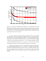
1
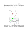
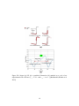
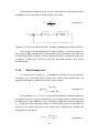
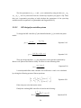
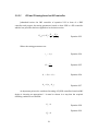
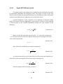
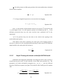
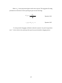
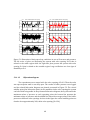
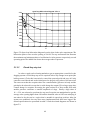
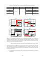
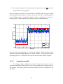
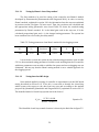
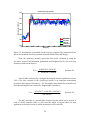
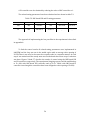
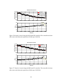
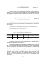
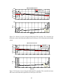
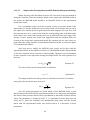
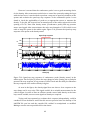
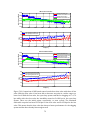
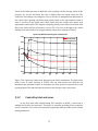
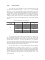
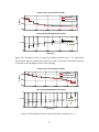
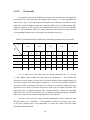
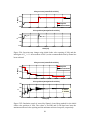
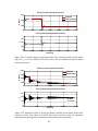
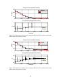
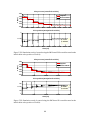
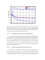
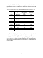
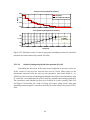
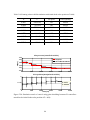
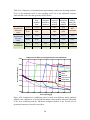
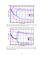
-0.0005606 S - 4.574e-05 P ( s ) 2 S 0.06858S 0.004006 Equation5.5 TheIMCcontroller(C)wasobtainedthenastheequation5.6(Seesection2.9.2.2). Avalueof 24.5 wasusedforthetimeconstantoftheclosed‐loopsystem.Thisvalue wasmanipulatedbytrialanderroruntilasatisfyinggain,phaseanddelaymarginwas obtainedforthecontroller. C 340.7491( S 0.005194S 0.000356) S ( S 0.0816) 2 Equation5.6 TheIMCcontrollerasasecondordertransferfunctionwasthenwritteninform ofaPIDcontrollerwithalow‐passfilterappliedonitsderivativeaction(Wemaysaya PIDFcontroller). APIcontrollerwasalsoobtainedbyreducingtheorderofIMCcontrollerto1. Therelatedtuningrulesareshownintable5.5. Table5.5:IMC‐basedPIDandPItuningparameters Kc0 Kc I D F PIDF 250 3.4736 2.3368 1189.9378 12.2552 PI 250 340.7491 229.2276 _ _ Thefunction“PIDAdvancedVI”fromLabVIEWwasusedtoimplementthelow‐ passfilterintheexperiments(seeappendixA). ThePIDtuningparameterswereimplementedinLabVIEW.Firstthesystemwas runinopen‐loopmannerwithamanualvalveopeningofZ=0.2anddatawerelogged. Then the loop was closed with a set‐point P=170 kPa that results in an average valve openingofZ=0.16.Aftercoupleofminutesitwastriedtodecreasetheset‐pointvaluein a stepwisemanner. At each step it was waited until the steady state was reached and then a new step of reduction was applied. The same was done with PI tuning parameters.Figures5.11and5.12describetheresultsofcontrolusingthe IMC‐based PID and PI controllers respectively. The experimental slugging system could be stabilizeduptoZ=0.30withIMC‐basedPIDcontrolleranduptoZ=0.29withIMC‐based PIcontroller. 61