1
4.2.4
Numericalsetting
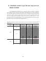
Thenumericalsettingspecificationssuchassimulationtimeandtimestepwere
adjusted in different numbers from case to case. This is due to the diversity of phase
velocityindifferentcases.
4.3
ImplementingPIDcontrollerinOLGA
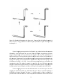
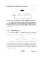
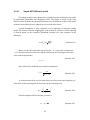
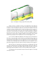
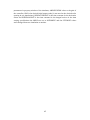
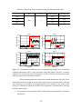
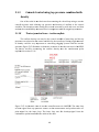
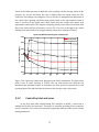
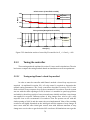
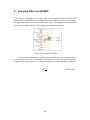
InordertoimplementaPIDcontrollerinOLGAfirstapositivecheckvalvewas
placedright afterthe water source in pipe2, section 1 of the case. The reason wasto
make sure that the flow will move only in the defined direction. Then a pressure
transmitterwaslocatedinpipe2,section2thatistheinletoftheriser,rightafterthe
buffertank.Itwasaimedtomeasurethebufferpressureandsendthepressuresignal
into the PID controller. The PID controller was used in a way that it received the
measurementsignalfromthepressuretransmitterandsenttheoutputsignalintothe
chokevalvelocatedattopoftheriser(Pipe8,section3).Chokevalvescanbesimulated
byselectingtheHydrovalveforthevalvemodelinOLGA.
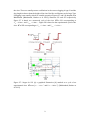
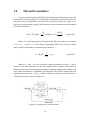
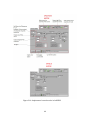
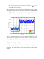
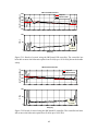
Figure 4.2: OLGA case with PID controller. The controller receives the measurement
signal from thepressure transmitter and sends the output signal into the choke valve
locatedattopoftheriser.
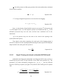
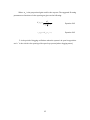
When applying a PID controller in OLGA several specifications need to be
established by user, depending on the desired conditions and results. The more
importantspecificationsthathavebeenmanipulatedmanytimesduringsimulationsare
the PID parameters and the time varying specifications. When it comes to PID
44