1
Am186™CC Microcontroller
Power Management Circuit
Application Note
by Gino Davis and Douglas Paulson
This application note describes the power use, design cosiderations, and functions of the
Am186™CC microcontroller power management circuit (PMC).
INTRODUCTION
Devices that operate efficiently at high speeds and low
voltages are essential for producing successful
products. This is achieved by innovative designs,
improved fab processes, better materials, and power
management. Power management plays an important
role in the power efficiency of a device to help it meet
stringent system power requirements and increased
mobile power supply longevity. Therefore, the
Am186CC™ microcontroller is combined with a power
management circuit capable of providing substantial
power savings.
The Am186CC microcontroller power management circuit (PMC) is modeled from and integrates the system
management principles of power supervision, compliance (to the standard to which you are designing), and
efficiency. Supervising power and its requirements and
assuring power is being used in the most efficient way
are simple and effective methods of power management design.
Because the CPU’s power use is directly related to the
frequency at which the CPU is running, managing the
operating frequency of the CPU is a major consideration in power consumption management. The stage or
present task required by the CPU determines at which
frequency the CPU runs to perform its task efficiently
and effectively. Ensuring that devices not in use are
shut down or in power-saving mode and configuring
PIOs to their most power-efficient state are essential to
power management. Software also plays an important
part in power management.
The core of the design can be used for a variety of
specifications. For the pur pose of example and
reference, we emulated the Am186CC microcontroller
PMC used in an ISDN TA with a telephone hand set.
This application includes three different power
requirements:
■ A normal power-consuming stage occurs when
power to the ISDN TA is available at the remote
location (the house or business where the phone is
© Copyright 1999 Advanced Micro Devices, Inc. All rights reserved.
located), in which there is no real power-saving
requirement.
■ A medium power-saving stage occurs when there is
no power available from the terminal adapter (TA)
remote location, and a call is being placed or
received. In this medium power stage, the ISDN TA
receives 450 mW of power from its central office.
■ A low-power stage occurs when no power is available from the ISDN TA remote location, and no call
is being attempted or received. In this case, the
ISDN TA only receives 25 mW of power from its central office, entering a very low power-saving mode.
Figure 1 and Figure 2 on page 2 illustrate the contents
of the design. The power to the ISDN TA is monitored
by the Frequency Select block using simple logic and
software. The power is also used to determine when
the Am186CC microcontroller is reset and to configure
the PLL of the Am186CC microcontroller. The HOOK
signal and the receiver ON-HOOK/OFF-HOOK switch
is also monitored by the Frequency Select block for
determining the appropriate frequency for the different
stages. The Pulse Control block ensures that the
Am186CC microcontroller does not receive any short
or runt pulses while switching frequencies on the fly in
the PLL Bypass mode. In addition, the Frequency
Output Control block ensures that only one frequency
outputs to the Am186CC microcontroller.
Although there are other methods of providing the
various frequencies to the CPU, this design uses three
different oscillators with different frequency speeds to
accommodate the application requirements. Also, the
switches for the POWERGOOD and HOOK SW circuit
shown in Figure 3 on page 3 are used for simulating
inputs to the circuit, and the switches are not needed
for functionality of the circuit.
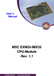
Figure 3 on page 3 and Table 1 on page 4 describe the
Am186CC microcontroller signals used by the application node.
Publication# 23111
Rev: A Amendment/0
Issue Date: November 1999
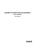
POWERGOOD
POWERGOOD (High)
POWER NOTGOOD (Low)
1) Enable 24 MHz oscillator
2) Reset board
3) Configure PLL to 2X mode
4) Hook SW is Don’t Care
1) Reset board
2) Configure PLL to BYPASS mode
3) Power Management code enabled
HOOK SW
OFF HOOK (High)
ON HOOK (Low)
1) Disables previous running oscillator
2) Enables 4 MHz oscillator
Figure 1.
1) Disables previous running oscillator
2) Enables 32.7 KHz oscillator
System Power Management Clocking/Timing Flow Chart
POWERGOOD – Functions as main power to the terminal adapter (TA):
■ POWERGOOD (logic level High): Power is available at the TA remote location.
■ POWER NOTGOOD (logic level Low): Power is not available at the TA remote location, functioning as a power
failure.
HOOK SW – Functions as a receiver on the TA being off or on hook:
■ ON HOOK (logic level Low): No outgoing or incoming call is being attempted.
■ OFF HOOK (logic level High): Either an outgoing or incoming call is being attempted.
2II+RRN2Q+RRN
Frequency
Select
3RZHU7R6\VWHP
Pulse
Control
Frequency
Output
Control
;
Reset
PLL Configure
5(6(7
&/.6(/
&/.6(/
Figure 2. Power Management Circuit Block Diagram
2
Am186™CC Microcontroller Power Management Circuit Application Note
12
27
40
48
59
68
78
91
106
120
125
133
148
160
79
77
VCC
X1
X2
CLKOUT
UCLK [USBSOF] [USBSCI] [PIO21]
USBX1
USBX2
30
31
32
36
37
42
43
44
45
49
50
64
65
69
70
84
85
88
89
90
A0
A1
A2
A3
A4
A5
A6
A7
A8
A9
A10
A11
A12
A13
A14
A15
A16
A17
A18
A19
28
34
38
46
51
66
86
92
29
35
39
47
52
67
87
93
107
109
110
111
112
113
145
146
147
115
124
105
14
15
98
99
CLKSEL1
PIO1
141
142
143
144
RES#
RESOUT
114
58
UCS# {ONCE#}
LCS# [RAS0#]
MCS0# {UCSX8#} [PIO4]
MCS1# [CAS1#]
MCS2# [CAS0#]
MCS3# [RAS1#] [PIO5]
PCS0# {USBSEL1} [PIO13]
PCS1# {USBSEL2} [PIO14]
PCS2#
PCS3#
PCS4# {CLKSEL2} [PIO3]
PCS5# {TESTMODE#} [PIO2]
PCS6# [PIO32]
PCS7# [PIO31]
132
131
126
127
128
129
5
6
7
8
9
10
11
13
RD#
WR# {PRODTST#} [PIO15]
WLB#
WHB#
ALE [PIO33]
DT/R# [PIO29]
DEN# [DS#] [PIO30]
BHE# {ADEN#} [PIO34]
AD0
AD1
AD2
AD3
AD4
AD5
AD6
AD7
AD8
AD9
AD10
AD11
AD12
AD13
AD14
AD15
Am186CC
Controller
AM186CC
S0# {USBXCVR#}
S1#
S2#
S6
BSIZE8#
QS0
QS1
RXDA [DDA] [RXDA]
TXDA [DUA] [TXDA]
RCLKA [DCLA] [CLKA]
TCLKA [FSCA] [FSCA]
CTSA# [TSCA#] [PIO17]
RTRA# [PIO18]
INT0
INT1
INT2
INT3
INT4
INT5
INT6 [PIO19]
INT7 [PIO7]
INT8 [PWD] [PIO6]
NMI
DRQ0 [PIO9]
DRQ1
ARDY [PIO8]
SRDY [PIO35]
HLDA {CLKSEL1}
HOLD
TMROUT0 [PIO28]
TMRIN0 [PIO27]
TMROUT1 [PIO1]
TMRIN1 [PIO0]
RXDB [RXDB] [PIO36]
TXDB [TXDB] [PIO37]
RCLKB [CLKB] [PIO40]
TCLKB [FSCB] [PIO41]
CTSB# [TSCB#] [PIO38]
RTRB# [PIO39]
RXDC [RXDC] [PIO42]
TXDC [TXDC] [PIO43]
RCLKC [CLKC] [PIO22]
TCLKC [FSCC] [PIO23]
CTSC# [TSCC#] [PIO44]
RTRC# [PIO45]
RXDU [RXDD] [RXDD] [PIO26]
TXDU [TXDD] [TXDD] [PIO20]
CTSU# [TCLKD] [FSCD] [PIO24]
RTRU# [RCLKD] [CLKD] [PIO25]
RXDHU [PIO16]
TXDHU
CTSHU# [CTSD#] [TSCD#] PIO46]
RTRHU# [RTRD#] [PIO47]
SDEN [PIO10]
SCLK [PIO11]
SDATA [PIO12]
VSS
VSS
VSS
VSS
VSS
VSS
VSS
VSS
VSS
VSS
VSS
VSS
VSS
VSS
VSSUSB
VSSA
USBD- [UDMNS]
USBD+ [UDPLS]
RSRVD1 [UXVRCV]
RSRVD2 [UXVEN#]
RSRVD3 [UTXDMNS]
RSRVD4 [UTXDPLS]
RESET
CLKSEL2
97
16
96
95
19
17
18
20
57
56
55
54
94
62
63
118
119
117
116
123
122
TCLKA
138
139
135
134
137
136
153
154
150
149
152
151
158
159
157
156
25
26
24
23
2
3
4
80
81
104
103
102
101
1
21
33
41
53
61
71
83
100
108
121
130
140
155
82
72
Am186™CC Microcontroller Power Management Circuit Application Note
73
74
60
22
75
76
VCC
VCC
VCC
VCC
VCC
VCC
VCC
VCC
VCC
VCC
VCC
VCC
VCC
VCC
VCCUSB
VCCA
U1
OSCILLATOR IN
Figure 3. Am186CC Microcontroller Signals Used With Power Management Circuit
UART LOWPOWER
OFF/ON HOOK
POWERGOOD
3
Table 1.
Signal Descriptions
Signal
Description
Configure PLL
(CLKSEL1,
CLKSEL2)
The two pins are used to configure the PLL to its various modes. The PLL can also be configured to 4x and
1x modes, but the 4x and 1x modes are not applicable in this reference.
•
When CLKSEL1 and CLKSEL2 are both Low, the PLL is configured to Bypass mode.
•
When CLKSEL1 and CLKSEL2 are both High, the PLL is configured to 2x mode.
For more information about CLKSEL1 and CLKSEL2, refer to the Am186™CC/CH/CU Microcontrollers
User’s Manual, order #21914B.
HOOK SW
Functions as a telephone receiver that is on or off the hook.
OSCILLATOR IN
Inputs one of three oscillator frequencies from the power management circuit to the Am186CC
microcontroller.
POWERGOOD
Functions as main power to the TA.
RESET
Resets the Am186CC microcontroller when the POWERGOOD signal is initiated to either the POWERGOOD
or POWER NOTGOOD state.
TCLKA
Drives the HDLC transmitter and is connected to and controlled by PIO1.
UART
LOWPOWER
PIO22 is used to put the UART’s transceiver into shutdown mode when in the power managed state.
VCC
Power is supplied to the TA at its remote location; general power to the entire application.
CIRCUIT OPERATION
This section provides a more detailed description of
how the circuit operates. Although this reference is
designed for a TA application with three separate
power requirement modes, the core of the design can
be applied to a wide range of applications. Figure 4 on
page 6 shows the sections of the Am186CC PMC
schematics. Figure 5 on page 7 shows the entire
Am186CC PMC schematics without boxes around
each section.
Frequency Select
■ When NOR-pwrgood gate inputs are High:
– 4-MHz and 32-KHz enabling flip-flops are
cleared, disabling the 4-MHz and 32-KHz oscillator regardless of the HOOK SW position.
– Enabling the active High 24-MHz oscillator and
driving a Low signal to input 1 of the NOR
24-MHz gate outputs the 24-MHz frequency to
X1.
■ When NOR-pwrgood gate inputs are Low:
– 24-MHz oscillator is disabled.
– 4-MHz and 32-KHz flip-flops are active and frequency selection is determined by the input to the
respective AND gate, which comes from the
HOOK SW position.
– When OFF HOOK:
4
Input 1 to the AND-onhk gate is Low, disabling
the 4-MHz oscillator.
Inputs 1 and 2 to AND-offhk are High, which
enables the 32-KHz oscillator and sends a Low
signal to the NOR-32-KHz gate, which outputs
the 32-KHz frequency to X1.
– When ON HOOK:
Input 1 to the AND-offhk gate is Low, disabling
the 32-KHz oscillator.
Inputs 1 and 2 to the AND-onhk gate are High,
which enables the 4-MHz oscillator and sends a
Low signal to NOR-4-MHz gate, which outputs a
4-MHz frequency to X1.
Pulse Safety
The PMC design requires changing between 4-MHz
and 32-KHz frequencies on the fly (without resetting
the processor). The two flip-flops in series ensure that
when alternating from 4-MHz to 32-KHz frequencies,
the Am186CC microcontroller continues to receive full
pulses. When alternating from 32-KHz to 4-MHz frequencies, shor t pulses are not a major concern
because the 32-KHz frequency periods are long. The
Am186CC microcontroller must be in the PLL Bypass
mode when alternating between frequencies. The
Am186CC microcontroller must receive a full pulse signal; shor t or runt pulses violate the Am186CC
microcontroller timing specification.
Am186™CC Microcontroller Power Management Circuit Application Note
Frequency Output Control
Three NOR gates control the frequency output to X1.
Whenever input 1 to NOR-32-KHz, NOR-4-MHz, or
NOR-24-MHz is Low, the respective gate outputs the
frequency on its input pin 2. Two or more of these NOR
gates never have a Low signal on pin 1 at the same
time.
■ 24-MHz Output: When pin 1 of the NOR-24-MHz
gate is Low, the 24-MHz frequency is driven on
pin 2 of this gate, outputting this frequency to pin 2
of the XOR-out gate. Meanwhile, the NOR-4-MHz
and 32-KHz gates are driving out High signals to
both the XOR-in gate pins, which in turn drives out
a Low signal to pin 1 of XOR-out. With pin 1 of the
XOR-out gate low, the XOR-out gate outputs the
frequency generated on its pin 2 to X1.
■ 4-MHz Output: When pin 1 of the NOR-4MHz gate
is Low, the 4-MHz frequency is being driven on pin
2 of this gate, outputting this frequency to pin 1 of
the XOR-in gate. Meanwhile, the NOR-32-KHz gate
is driving out a Low signal to pin 2 of the XOR-in
gate. With pin 2 of the XOR-in gate Low, the frequency generated on pin 1 is outputted to input pin
1 of the XOR-out gate while the NOR-24 MHz gate
is driving a Low signal to pin 2 the of XOR-out gate.
With pin 2 of the XOR-out gate Low, the XOR-out
gate outputs the frequency generated on its input
pin 1 to X1.
■ 32-KHz Output: When pin 1 of the NOR-32-KHz
gate is Low, the 32-KHz frequency is being driven
on pin 2 of this gate, outputting this frequency to pin
2 of the XOR-in gate. Meanwhile, the NOR-4-MHz
gate is driving out a Low signal to pin 1 of the XORin gate. With pin 1 of the XOR-in gate Low, the frequency being generated on pin 2 is being outputted
to input pin 1 of the XOR-out gate while the NOR24-MHz gate is driving a Low signal to pin 2 the of
XOR-out gate. With pin 2 of the XOR-out gate Low,
the XOR-out gate outputs the frequency generated
on its input pin 1 to X1.
Reset
XOR-reset is used for generating a reset to the
Am186CC microcontroller with the initiation of a
POWERGOOD or a POWER NOTGOOD signal.
AND-reset is used for an initial board power-up reset.
PLL Configuration
These two outputs are connected to HLDA(CLKSEL1)
and PCS4(CLKSEL2) of the Am186CC microcontroller
to configure the PLL to 2x mode when the signal is
POWERGOOD, or to PLL Bypass mode when the signal is POWER NOTGOOD.
Am186™CC Microcontroller Power Management Circuit Application Note
5
6
VCC
VCC
VCC
VCC
11k
FREQUENCY SELECT
11k
PULSE SAFTEY
11k
B
3
1
Q
11k
Q
ENABLE 4MHz
5
FREQUENCY OUTPUT CONTROL
CLK
INV
6
2
D
3
CLK
1
A
VCC
Q
Q
5
2
D
3
CLK
6
Q
Q
5
6
1
1
2
Y
1
11k
2
Y
3
B
VCC
U?
1
2
A
Y
3
2
B
3
D
Q
5
1
ENABLE 32 KHz
4
CLK
EN
OUT
5
GND
VCC
8
VCC
Q
1
A
2
B
U?
Y
3
1
2
A
Y
3
B
XOR-in
4 MHz Oscil
CL
AND-offhk
PR
4
VCC
A
NOR-4MHz
XOR-out
6
1
2
1
Am186™CC Microcontroller Power Management Circuit Application Note
AND-onhk
D
4
2
PR
3
Y
CL
A
4
2
PR
1
CL
2
PR
Y
A
Schmitt Trigger
CL
1
4
HOOK SW
A
Y
3
Y
3
B
NOR-32KHz
VCC
5
OUT
EN
1
8
VCC
GND
4
U?
1
2
32.7KHz Oscil
VCC
1
A
2
B
Y
B
NOR-24MHz
When input 1 to a NOR gate is low
that particular frequency is
selected.
RESET
24MHz
A
3
VCC
NOR-pwrgood
Serves as an INVERTER
11K
100K
POWERGOOD
100K
1
A
Y
2
Schmitt Trigger
0.1 uF
0.1 uF
U?
1
2
A
Y
3
1
A
2
B
B
RESET#
Y
3
AND-reset
XOR-reset
ENABLE 24 MHz
1
4
EN
OUT
GND
VCC
5
VCC
8
24 MHz Oscil
PLL CONFIGURATION
11K
HLDA {CLKSEL1}
11K
PCS4 {CLKSEL2}
(C) Advanced Micro Devices, Inc.
5204 E. Ben White Blvd.
Austin, TX 78741
AMD Proprietary/All Rights Reserved
Title
186CC Power Management
Size
Figure 4.
Power Management Circuit Schematic In Sections
Document Number
Logic Grouped Circuit
(800) 222-9323
VCC
VCC
D
D
VCC
VCC
11k
11k
11k
11k
3
2
D
1
Q
ENABLE 4MHz
5
6
2
D
3
5
Q
2
3
CLK
1
INV
Q
CLK
A
D
6
Q
Q
Q
5
CLK
6
1
1
2
CL
VCC
Y
1
A
2
B
11k
VCC
3
NOR-4MHz
U?
4
VCC
Y
2
C
1
A
Y
3
B
D
3
CLK
Q
EN
ENABLE 32KHz
5
4
GND
OUT
VCC
1
A
2
B
5
VCC
8
U?
Y
3
1
A
2
B
XOR-in
Q
Y
3
X1
C
XOR-out
4 MHz Oscil
CL
AND-offhk
2
PR
1
6
1
A
2
B
1
Am186™CC Microcontroller Power Management Circuit Application Note
3
4
Y
AND-onhk
PR
B
CL
2
4
A
PR
Schmitt Trigger
1
PR
Y 2
CL
1 A
4
HOOK SW
Y
3
Y
3
NOR-32kHz
5
VCC
8
OUT
EN
VCC
GND
U?
1
1
A
2
B
4
32.7KHz Oscil
NOR-24MHz
Serves as an INVERTER
1
VCC
B
2
A
Y
3
B
B
NOR-pwrgood
VCC
11K
100K
POWERGOOD
100K
1 A
Y 2
Schmitt Trigger
0.1 uF
0.1 uF
U?
1
2
A
Y
3
1
A
2
B
B
RESET#
Y
3
AND2
XOR2
ENABLE 24 MHz
1
4
EN
OUT
GND
VCC
5
VCC
8
24 MHz Oscil
A
A
11K
11K
(C) Advanced Micro Devices, Inc.
HLDA {CLKSEL1}
(800) 222-9323
5204 E. Ben White Blvd.
Austin, TX 78741
AMD Proprietary/All Rights Reserved
PCS4 {CLKSEL2}
Title
186CC Power Management
Size
Figure 5.
Power Management Circuit Schematic
Document Number
Logic Circuit
Rev
1.0
7
MEASUREMENTS
Test Conditions
efficiency than that described in this application note by
using better power-efficient parts and practicing good
programming methodology.
The PMC is tested with an Am186CC microcontroller
reference design ISDN TA board. All devices not
applicable to the test were removed from the board,
leaving the CPU, DRAM, Flash memory, and a UART
for loading code. Because the board is not designed
with power management in mind, it utilizes +5-V DRAM
an d Fl as h me m or y dev i c e s, even t ho ug h th e
Am186CC microcontroller is a 3.3-V device. The ISDN
TA board uses 5-V memory devices with a 3.3-V
microcontroller to accommodate the S/T controller for
the ISDN TA applications. Anyone interested in
designing a power management system and/or
application with the Am186CC microcontroller should
use CMOS 3.3-V memory to utilize power more
efficiently. Although the ISDN TA board is not designed
for this particular application, it provides a platform for
demonstrating and testing the PMC.
Table 2 contains a sample of a test measurements
taken under various conditions to establish expected
baseline current draw values.
Power Measurement Descriptions
VCC
Am186CC microcontroller digital current
draw
VCCA
Am186CC microcontroller analog current
draw
DRAM
+5-V high-performance CMOS dynamic
RAM
FLASH
+5-V CMOS Flash memory
TRANS
+5-V RS232 transceiver
General Power Measurements
OTHER
I t i s i m p o r t a n t t o n o t e t h a t a l l o f t h e p o we r
measurements derived from these test conditions and
documented in this application note show what to
expect when following the guidelines described in this
document. However, you can obtain better power
Other parts on the board such as the system
crystal and the 3.3-V LDO that collectively
consume measurable current draw
PM CIR
The total current draw of the PMC (in
Table 3 only)
TOTAL
The total current draw of the entire board
Table 2. General Power Measurements
CODE
CPU SPEED
VCC
VCCA
DRAM
FLASH
TRANS
OTHER
TOTAL
1
48 MHz
119
5.2
1.5
22.1
19.75
12.45
180.3
2
48 MHz
115.2
4.6
88.1
–
10.7uA
12.5
220.6
3
48 MHz
116.1
4.45
87.3
–
18.65
11.8
238.3
Note: All values are in mA unless otherwise specified.
Row 1 contains measurements taken with code that is
designed to keep the CPU busy, simulating maximum
use of the Am186CC microcontroller. All four HDLC
channels are in loopback at 1/8 clock speed. All three
timers are running: one timer drives the TCLK pin of all
four HDLC channels; the two other timers are in a continuous loop, but their outputs are not driving any PIO
pins. The High Speed UART is continuously busy while
all unused PIOs are set up as inputs. The code is written in assembly language and is designed to run from
Flash memory, and not DRAM. Although the VCC in
row 1 in Table 2 is the highest value of the three VCC
values, the TOTAL value in row 1 is the lowest value of
the three TOTAL values. This condition is caused by
running the code from the Flash instead of the DRAM,
which saves power.
Row 2 contains code that puts the UART transceiver in
Shutdown mode, runs four HDLCs, uses one timer to
drive the HDLCs’ transmit clock, and runs one timer
8
constantly while the third timer is off. The code also
accesses the S/T interface and synchronous serial
interface (SSI) to simulate a ter minal adapter
application. This version of code is wr itten in
C language and runs out of DRAM, which shows a
significant increase in total system power draw even
though nearly 20 mA is eliminated by putting the UART
transceiver in Shutdown mode. This condition is
caused by the DRAM’s increased power consumption,
which is caused by the code language and the typical
requirement that DRAM needs to be constantly
refreshed.
The code in Row 3 is identical to the code in Row 2 except the UART transceiver is not put in Shutdown
mode, and only two HDLCs are running. The total increase in total-system current draw reflects the UART
transceiver running and indicates that the HDLCs do
not draw a significant amount of current.
Am186™CC Microcontroller Power Management Circuit Application Note
Power Management Measurements
based on measurements taken under the test
conditions described in Table 3. The current rate is a
typical representation of what customers can see in
their application designs.
Table 3 contains the power measurement values taken
with the PMC attached to the Am186CC and using
code that monitors the power input to the system and
manages the power consumption according to the
different stage needs.
NOTE: This measurement only applies when the
microcontroller is run at higher frequencies (e.g.,
4-MHz and above). At lower frequencies, this
measurement tends to increase due to an Icc constant
that is always present but less apparent at higher
frequencies.
The system running at 48 MHz indicates that full power
is being supplied to the simulated TA; therefore, no
power management is required. The total current
c o n s u mp t i o n i s h i gh e r th a n t h e t o ta l c u r r e n t
consumption of the Code 3 values in Table 1 because
of the additional current draw of the PMC.
POWER MANAGEMENT KEY POINTS
The system running at 4 MHz indicates that the TA is
not receiving power from the remote location and is receiving limited power from the phone company through
the phone line for an incoming or outgoing call. This
causes the PMC to enable the 4-MHz oscillator. This
triggers the PM code, disabling address multiplexing on
the data bus, putting the UART transceiver in Shutdown
mode, configuring unused PIOs as high-impedance inputs, and transmitting the HDLC in low power mode.
Although the PMC is designed for a simulated TA
application with three different power requirements, the
circuit is easily tailored for other specifications and/or
applications. For example, if your application only
required two different power modes utilizing a 25-MHz
frequency at 2x PLL mode and a 12-MHz frequency in
PLL Bypass mode, the following are some of the major
PMC modifications for these specifications:
■ Replace the 24-MHz oscillator with the 25-MHz
crystal.
The 32.7-KHz measurements result from no power
being supplied from the remote location and no incoming or outgoing call being attempted. The PMC enables
the 32.7-KHz oscillator and the PM code. Then the
PMC puts the Am186CC microcontroller in Halt mode
and periodically brings the microcontroller out of Halt
mode to check for incoming or outgoing calls. The fluctuating current in DRAM is caused by the CPU going in
and out of Halt mode, thus having fluctuating current in
the TOTAL measurement. Although not evident, the
VCC current also varies, but in the µA range, which is
not apparent in the VCC measurement.
■ Remove the AND-offhk, the 32-KHz enable flip-flop,
the 32-KHz oscillator, and the NOR-32-KHz gate.
■ Remove the two Pulse Safety flip-flops. This is
optional. Because the frequency is not switched on
the fly, the two Pulse Safety flip-flops are not
required.
■ Replace the 4-MHz oscillator with the 12-MHz oscillator.
■ Tie the Q output of the 12-MHz flip-flop to the A
input of the NOR-4-MHz gate, which is now called
the NOR-12-MHz gate.
Typical Icc currents, being very low, are measured to be
approximately 2.5–3.0 µA/MHz. This low Icc rate not
only enables low-power consumption but also
contributes to a low EMI signature. This current rate is
■ Remove the XOR-in gate and tie the output of
NOR-12-MHz gate to the A input of XOR-out gate.
Table 3. Power Management Measurements
CPU SPEED
VCC
VCCA
DRAM
FLASH
TRANS
PM CIR
OTHER
TOTAL
48 MHz
117
5.4
87
–
18.7
17
12.4
257.5
4 MHz
11.6
0.7
12.6
–
12 uA
8.2
1.4
34.5
32.7 KHz
1.75
0.13
0.4 - 1.1
–
12 uA
1.8
0.1 - 1
4-6
Notes:
1. All values are in mA unless otherwise specified.
2. The code for generating the measurements in this table can be found in the Am186™CC Microcontroller Power Management
CodeKit Software, V1.0, May 18, 1999.
Am186™CC Microcontroller Power Management Circuit Application Note
9
Again, this is just an example of how the circuit can be
made to accommodate different system requirements.
Proper termination of unused PIO pins are important in
achieving low power. Because most PIOs have
alternate functions and some have either internal
pullups, internal pulldowns, or Schmitt Trigger Inputs, it
is impor tant to consult the Am186™CC/CH/CU
Microcontroller User’s Manual (order #21914) for
proper termination of unused PIOs.
Running your code from the most efficient memory
possible is also a contributing factor to power
management. As indicated by the measurements in
Table 1, the TOTAL measurement is low (although Row
1 shows the VCC is drawing more current, indicating
that the CPU is working harder) because the code is
being executed out of Flash memory, which is the more
efficient memory in this case.
When there is no activity in the system, executing the
HALT command (which puts the system in Halt mode)
is recommended. Depending on the particular system
design, putting the processor in Halt mode can save
the total system power as much as 20%.
SUMMARY
Power managing the Am186CC microcontroller
depends largely on managing the system speed
(frequency) as efficiently as possible. The PMC is
designed to handle most of this for you by monitoring
key signals and switching to the appropriate frequency
when needed. Software plays a key role in managing
the Am186CC microcontroller by monitoring the
frequency at which the system is running to determine
when to take additional power-saving measures, such
as configuring the PIOs, putting peripheral devices in
Low or Shutdown mode, and even putting the
Am186CC mi crocontroller in Halt mode when
necessary.
The PMC, combined with good software methodology,
provides good power management for the Am186CC
microcontroller, enabling it to meet many stringent
power requirements.
Trademarks
AMD, the AMD logo, and combinations thereof, and Am186 are trademarks of Advanced Micro Devices, Inc.
Other product names used in this publication are for identification purposes only and may be trademarks of their respective companies.
Disclaimer
The contents of this document are provided in connection with Advanced Micro Devices, Inc. ("AMD") products. AMD makes no representations
or warranties with respect to the accuracy or completeness of the contents of this publication and reserves the right to make changes to specifications and product descriptions at any time without notice. No license, whether express, implied, arising by estoppel or otherwise, to any intellectual property rights is granted by this publication. Except as set forth in AMD’s Standard Terms and Conditions of Sale, AMD assumes no
liability whatsoever, and disclaims any express or implied warranty, relating to its products including, but not limited to, the implied warranty of
merchantability, fitness for a particular purpose, or infringement of any intellectual property right.
AMD’s products are not designed, intended, authorized or warranted for use as components in systems intended for surgical implant into the
body, or in other applications intended to support or sustain life, or in any other application in which the failure of AMD’s product could create a
situation where personal injury, death, or severe property or environmental damage may occur. AMD reserves the right to discontinue or make
changes to its products at any time without notice.
10
Am186™CC Microcontroller Power Management Circuit Application Note