1
Freescale Semiconductor, Inc.
M68HC16Z1EVB/D
Rev. 1
Freescale Semiconductor, Inc...
April 1998
M68HC16Z1EVB
USER’S MANUAL
© MOTOROLA, INC., 1991, 1998; All Rights Reserved
For More Information On This Product,
Go to: www.freescale.com
Freescale Semiconductor, Inc...
Freescale Semiconductor, Inc.
Motorola reserves the right to make changes without further notice to any products herein to
improve reliability, function or design. Motorola does not assume any liability arising out of the
application or use of any product or circuit described herein; neither does it convey any license
under its patent rights nor the rights of others. Motorola products are not designed, intended, or
authorized for use as components in systems intended for surgical implant into the body, or other
applications intended to support or sustain life, or for any other application in which the failure of
the Motorola product could create a situation where personal injury or death may occur. Should
Buyer purchase or use Motorola products for any such unintended or unauthorized application,
Buyer shall indemnify and hold Motorola and its officers, employees, subsidiaries, affiliates, and
distributors harmless against all claims, costs, damages, and expenses, and reasonable attorney
fees arising out of, directly or indirectly, any claim of personal injury or death associated with
such unintended or unauthorized use, even if such claim alleges that Motorola was negligent
regarding the design or manufacture of the part.
IBM-PC is a registered trademark of International Business Machines Corp.
EVB16 and the PAL firmware are © P & E Microcomputer Systems, Inc.*, 1990, 1991; All
Rights Reserved. Portions of the software are
© Borland International, 1987. Portions of the software are
© TurboPower Software, 1988.
*
P & E Microcomputer Systems, Inc.,
PO Box 2044
Woburn, MA 01888-2044
(617)-944-7585
For More Information On This Product,
Go to: www.freescale.com
Freescale Semiconductor, Inc.
CONTENTS
CONTENTS
Freescale Semiconductor, Inc...
CHAPTER 1
1.1
1.2
1.3
1.4
1.5
1.6
GENERAL INFORMATION
INTRODUCTION............................................................................................................. 1-1
FEATURES....................................................................................................................... 1-1
SPECIFICATIONS ........................................................................................................... 1-2
GENERAL DESCRIPTION ............................................................................................. 1-3
EQUIPMENT REQUIRED............................................................................................... 1-3
CUSTOMER SUPPORT .................................................................................................. 1-4
CHAPTER 2
HARDWARE PREPARATION AND INSTALLATION
2.1
2.2
2.3
INTRODUCTION............................................................................................................. 2-1
UNPACKING INSTRUCTIONS...................................................................................... 2-1
HARDWARE PREPARATION ....................................................................................... 2-1
2.3.1 RAM/EPROM Select Headers (J1—J4).................................................................... 2-4
2.3.2 Memory Devices (U1-U4) and Byte/Word Select Header (J5)................................. 2-6
2.3.3 P1, P2 +5-Volt Select Header (J6)............................................................................. 2-9
2.3.4 Memory Access Fault Prevention Header (J7).......................................................... 2-9
2.3.5 P5, P6 +5-Volt Select Header (J8)........................................................................... 2-10
2.3.6 RXD Connect Header (J9)....................................................................................... 2-10
2.3.7 TXD Connect Header (J10) ..................................................................................... 2-11
2.3.8 Clock Select Headers (J11, J12, J14) ...................................................................... 2-11
2.3.9 Factory Test Header (J13)........................................................................................ 2-12
2.3.10 D/A Select Headers (J15—J17)............................................................................... 2-12
2.4 INSTALLATION INSTRUCTIONS.............................................................................. 2-13
2.4.1 Power Supply—EVB Connection (P8).................................................................... 2-13
2.4.2 Computer—PC Printer Port Connection (P9) ......................................................... 2-13
2.4.3 Computer—User Interface Port Connection (P10).................................................. 2-14
2.4.4 Logic Analyzer—EVB Connections (P1—P7) ....................................................... 2-16
M68HC16Z1EVB/D — Rev 1
For More Information On This Product,
Go to: www.freescale.com
iii
Freescale Semiconductor, Inc.
CONTENTS
CHAPTER 3
EVB16 OPERATING PROCEDURE
Freescale Semiconductor, Inc...
3.1
INTRODUCTION............................................................................................................. 3-1
3.1.1 Typeface and Parameter Conventions ....................................................................... 3-1
3.1.2 EVB16 Numerical Formats ....................................................................................... 3-2
3.2 STARTUP ......................................................................................................................... 3-3
3.3 MAIN SCREEN................................................................................................................ 3-4
3.3.1 CPU Window............................................................................................................. 3-4
3.3.2 Instruction Pointer (IP) Window................................................................................ 3-5
3.3.3 Breakpoint (BR) Window.......................................................................................... 3-5
3.3.4 Code Window ............................................................................................................ 3-5
3.3.5 Memory Windows ..................................................................................................... 3-6
3.3.6 Debug Window.......................................................................................................... 3-6
3.3.7 Window Function Keys ............................................................................................. 3-6
3.4 GENERAL USE................................................................................................................ 3-7
3.5 DEBUG WINDOW COMMANDS.................................................................................. 3-7
3.6 SOURCE-LEVEL DEBUGGING................................................................................... 3-23
3.7 TRACE BUFFER............................................................................................................ 3-25
CHAPTER 4
MASM16 OPERATING PROCEDURE
4.1
INTRODUCTION............................................................................................................. 4-1
4.1.1 System Requirements ................................................................................................ 4-1
4.1.2 System Overview....................................................................................................... 4-2
4.1.3 Getting Started ........................................................................................................... 4-3
4.2 HOTKEYS ........................................................................................................................ 4-4
4.3 MENU SYSTEM .............................................................................................................. 4-5
4.4 SETTING OPTIONS ........................................................................................................ 4-8
4.5 HELP............................................................................................................................... 4-10
4.6 EDITOR .......................................................................................................................... 4-11
4.6.2 Prompt Editor .......................................................................................................... 4-12
4.6.3 Tabs.......................................................................................................................... 4-12
4.6.4 Window Commands ................................................................................................ 4-13
4.6.5 Cursor Commands ................................................................................................... 4-14
4.6.6 Insert and Delete Commands................................................................................... 4-17
4.6.7 Block Commands..................................................................................................... 4-19
iv
M68HC16Z1EVB/D — Rev 1
For More Information On This Product,
Go to: www.freescale.com
Freescale Semiconductor, Inc.
CONTENTS
Freescale Semiconductor, Inc...
CHAPTER 4
MASM16 OPERATING PROCEDURE (continued)
4.6.8 Miscellaneous Commands ....................................................................................... 4-21
4.6.8.1 The Find Command ........................................................................................ 4-23
4.6.8.2 The Find-and-Replace Command................................................................... 4-24
4.7 ASSEMBLER ................................................................................................................. 4-25
4.7.1 Labels....................................................................................................................... 4-25
4.7.2 Operations................................................................................................................ 4-26
4.7.3 Operands .................................................................................................................. 4-26
4.7.3.1 Constants ........................................................................................................ 4-26
4.7.3.2 Operators......................................................................................................... 4-27
4.7.4 Comments ................................................................................................................ 4-27
4.7.5 Assembler Directives............................................................................................... 4-28
4.7.6 Include ..................................................................................................................... 4-32
4.7.7 Macros ..................................................................................................................... 4-32
4.7.8 Conditional Assembly ............................................................................................. 4-33
CHAPTER 5
5.1
5.2
INTRODUCTION............................................................................................................. 5-1
EVB DESCRIPTION........................................................................................................ 5-1
5.2.1 MCU and Control Circuits ........................................................................................ 5-1
5.2.2 User Memory ............................................................................................................. 5-3
5.2.3 Terminal I/O Port....................................................................................................... 5-5
CHAPTER 6
6.1
6.2
SUPPORT INFORMATION
INTRODUCTION............................................................................................................. 6-1
CONNECTOR SIGNAL DESCRIPTIONS...................................................................... 6-1
APPENDIX A
A.1
A.2
A.3
A.4
A.5
FUNCTIONAL DESCRIPTION
S-RECORD INFORMATION
INTRODUCTION.............................................................................................................A-1
S-RECORD CONTENT ...................................................................................................A-1
S-RECORD TYPES..........................................................................................................A-3
S-RECORD CREATION..................................................................................................A-4
S-RECORD EXAMPLE ...................................................................................................A-4
M68HC16Z1EVB/D — Rev 1
For More Information On This Product,
Go to: www.freescale.com
v
Freescale Semiconductor, Inc.
CONTENTS
FIGURES
2-1.
2-2.
3-1.
5-1.
5-2.
Jumper Header and Connector Location Diagram.......................................................... 2-33
RAM/EPROM Select Header Configurations................................................................... 2-5
EVB16 Main Screen.......................................................................................................... 3-4
HC16Z1EVB Block Diagram ........................................................................................... 5-2
HC16Z1 Memory Map...................................................................................................... 5-4
Freescale Semiconductor, Inc...
TABLES
1-1.
2-1.
2-2.
3-1.
3-2.
3-3.
3-4.
4-1.
4-2.
4-3.
4-4.
4-5.
4-6.
4-7.
4-8.
4-9.
6-1.
6-2.
6-3.
6-4.
6-5.
6-6.
6-7.
6-8.
6-9.
6-10.
6-11.
A-1.
A-2.
vi
EVB Specifications ........................................................................................................... 1-2
Memory Device Pin Signals.............................................................................................. 2-8
Memory Device Pin Signals.............................................................................................. 2-8
EVB16 Number Symbols.................................................................................................. 3-2
EVB16 Special Function Keys.......................................................................................... 3-6
Debug Window Commands .............................................................................................. 3-8
Code Window Commands .............................................................................................. 3-24
MASM16 Hotkeys ............................................................................................................ 4-4
MASM16 Menus............................................................................................................... 4-5
Edit Window Status Line Information ............................................................................ 4-11
Editor Window Commands............................................................................................. 4-13
Editor Cursor Commands................................................................................................ 4-14
Editor Insert and Delete Commands ............................................................................... 4-17
Editor Block Commands ................................................................................................. 4-19
Editor Miscellaneous Commands ................................................................................... 4-21
Assembler Directives ...................................................................................................... 4-28
Logic Analyzer Connector P1 Pin Assignments............................................................... 6-2
Logic Analyzer Connector P2 Pin Assignments............................................................... 6-2
Logic Analyzer Connector P3 Pin Assignments ............................................................... 6-3
Logic Analyzer Connector P4 Pin Assignments............................................................... 6-5
Logic Analyzer Connector P5 Pin Assignments............................................................... 6-7
Logic Analyzer Connector P6 Pin Assignments............................................................... 6-9
Logic Analyzer Connector P7 Pin Assignments............................................................. 6-11
Input Power Connector P8 Pin Assignments .................................................................. 6-11
PC Printer Port Connector P9 Pin Assignments ............................................................. 6-12
User Interface Port Connector P10 Pin Assignments...................................................... 6-13
D/A Conversion Power Connector P11 Pin Assignments .............................................. 6-13
S-Record Field Composition.............................................................................................A-2
S-Record Types.................................................................................................................A-3
M68HC16Z1EVB/D — Rev 1
For More Information On This Product,
Go to: www.freescale.com
Freescale Semiconductor, Inc.
GENERAL INFORMATION
CHAPTER 1
GENERAL INFORMATION
Freescale Semiconductor, Inc...
1.1 INTRODUCTION
This manual provides general information, hardware preparation, installation
instructions, operating instructions, functional description, and support
information for the M68HC16Z1EVB Evaluation Board (EVB). Appendix A
contains EVB downloading S-record information.
The EVB consists of the M68HC16Z1EVB printed circuit board (PCB) plus
development software.
1.2 FEATURES
EVB features include:
• An economical means of evaluating target systems incorporating
MC68HC16Z1 HCMOS microcontroller unit (MCU) devices.
• Background-mode operation, for detailed operation from a personal
computer (PC) platform without an on-board monitor.
• Integrated assembly/editing/emulation environment for easy development.
• As many as seven software breakpoints.
• Memory map of your target system.
• RS-232C terminal input/output (I/O) port.
• Logic analyzer pod connectors.
M68HC16Z1EVB/D — Rev 1
For More Information On This Product,
Go to: www.freescale.com
1-1
Freescale Semiconductor, Inc.
GENERAL INFORMATION
1.3 SPECIFICATIONS
Table 1-1 lists EVB specifications.
Table 1-1. EVB Specifications
Freescale Semiconductor, Inc...
Characteristic
Specifications
Internal Clock
16.78 MHz bus operation (32 kHz crystal controlled,
with on-chip phase lock loop)
External Clock
25—50 kHz
Pseudo ROM maximum memory
EPROM:
32 K bytes x 16 (word mode)(1)
32 K bytes x 8 (byte mode)
RAM:
32 K bytes x 16 (word mode)(1)
32 K bytes x 8 (byte mode)
Data RAM maximum memory
64 K bytes:
32 K bytes x 16 (word mode)(1)
32 K bytes x 8 (byte mode)
MCU I/O ports
HCMOS compatible
Monitor interface
Centronics parallel compatible
Optional development interface
RS-232C compatible
Temperature
Operating
Storage
+25° C
-40° to +85° C
Relative humidity
0 to 90% (non-condensing)
Power requirements
+5 Vdc @ 1.0 A (max)
Dimensions
9.5 x 6.6 in. (241 x 190 mm)
(1) See paragraph 2.3.2 for an explanation of word and byte modes.
1-2
M68HC16Z1EVB/D — Rev 1
For More Information On This Product,
Go to: www.freescale.com
Freescale Semiconductor, Inc.
GENERAL INFORMATION
1.4 GENERAL DESCRIPTION
Freescale Semiconductor, Inc...
The EVB is an economical tool for designing, debugging, and evaluating
MC68HC16Z1 MCU operation. The factory ships the EVB with a resident
MC68HC16Z1 MCU device. By providing the essential MCU timing and I/O
circuitry, the EVB simplifies user evaluation of prototype hardware/software
products. The EVB requires a user-supplied power supply and host computer.
For communication with the EVB, the user needs a personal computer (PC), with
a Centronics-type parallel port. The P&E software included with the EVB uses the
parallel port for communications. The EVB also has an RS-232 serial port for user
access to the on-chip serial communication interface (SCI) (although this port is
not used with the EVB16 development system software).
The EVB operates in background mode: a backdoor method of talking to the CPU
core.
There are two methods of generating MCU code:
1. Using the EVB one-line assembler/disassembler.
2. Downloading assembled code from an external source to user program
RAM (pseudo ROM) via EVB16 (that is, through the background mode
port).
The EVB includes jumper-selectable options such as clock source selection, ROM
or RAM selection, and memory size selection. The EVB offers various operating
configurations for the optional data converters. A switch lets the user reset EVB
circuitry.
1.5 EQUIPMENT REQUIRED
The external requirements for EVB operation are a +5 Vdc power supply and a
host computer. The computer must run under MS-DOS, PC-DOS, or Dr-DOS,
and must have a Centronics-compatible interface port and cable assembly.
For optional analog/digital(A/D) data conversion, the user also must supply a
Burr-Brown PCM56P device (for EVB location U12) and -8 Vdc to -15 Vdc
power.
M68HC16Z1EVB/D — Rev 1
For More Information On This Product,
Go to: www.freescale.com
1-3
Freescale Semiconductor, Inc.
GENERAL INFORMATION
1.6 CUSTOMER SUPPORT
For information about a Motorola distributor or sales office near you call:
AUSTRALIA, Melbourne – (61-3)887-0711
Sydney – 61(2)906-3855
Freescale Semiconductor, Inc...
BRAZIL, Sao Paulo – 55(11)815-4200
CANADA, B. C., Vancouver – (604)606-8502
ONTARIO, Toronto – (416)497-8181
ONTARIO, Ottawa – (613)226-3491
QUEBEC, Montreal – (514)333-3300
JAPAN, Fukuoka – 81-92-725-7583
Gotanda – 81-3-5487-8311
Nagoya – 81-52-232-3500
Osaka – 81-6-305-1802
Sendai – 81-22-268-4333
Takamatsu – 81-878-37-9972
Tokyo – 81-3-3440-3311
KOREA, Pusan – 82(51)4635-035
Seoul – 82(2)554-5118
CHINA, Beijing – 86-10-68437222
MALAYSIA, Penang – 60(4)2282514
DENMARK – (45)43488393
FINLAND, Helsinki – 358-9-6824-400
MEXICO, Mexico City – 52(5)282-0230
Guadalajara – 52(36)21-8977
FRANCE, Paris – 33134 635900
PUERTO RICO, San Juan – (809)282-2300
GERMANY,
Langenhagen/Hannover – 49(511)786880
Munich – 49 89 92103-0
Nuremberg – 49 911 96-3190
Sindelfingen – 49 7031 79 710
Wiesbaden – 49 611 973050
SINGAPORE – (65)4818188
HONG KONG, Kwai Fong – 852-6106888
Tai Po – 852-6668333
SPAIN, Madrid – 34(1)457-8204
SWEDEN, Solna – 46(8)734-8800
SWITZERLAND, Geneva – 41(22)799 11 11
Zurich – 41(1)730-4074
TAIWAN, Taipei – 886(2)717-7089
INDIA, Bangalore – (91-80)5598615
THAILAND, Bangkok – 66(2)254-4910
ISRAEL, Herzlia – 972-9-590222
UNITED KINGDOM, Aylesbury – 441(296)395-252
ITALY, Milan – 39(2)82201
UNITED STATES, Phoenix, AZ – 1-800-441-2447
For a list of the Motorola sales offices and distributors:
http://www.mcu.motsps.com/sale_off.html
1-4
M68HC16Z1EVB/D — Rev 1
For More Information On This Product,
Go to: www.freescale.com
Freescale Semiconductor, Inc.
HARDWARE PREPARATION AND INSTALLATION
CHAPTER 2
HARDWARE PREPARATION AND INSTALLATION
Freescale Semiconductor, Inc...
2.1 INTRODUCTION
This chapter provides unpacking instructions, hardware preparation information,
and installation instructions for the EVB.
2.2 UNPACKING INSTRUCTIONS
NOTE
Should the product arrive damaged, save all packing material, and
contact the carrier’s agent.
Unpack the EVB from its shipping carton. Refer to the packing list and verify that
all items are present. Save packing material for storing and shipping the EVB.
2.3 HARDWARE PREPARATION
The user should inspect and prepare the EVB before use. This portion of text
explains how to do this, as well as how to configure the EVB for the system
operation the user needs.
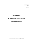
The EVB has been factory-tested; it is shipped with factory-installed jumpers.
Figure 2-1 shows the locations of jumper headers and connectors.
Connectors P1 through P7 are the logic analyzer connectors. Connector P8 is for
system power and connector P9 is the PC printer port. Connector P10 is the
optional RS-232 interface connector, for user code development. Connector P11 is
an additional power connector for the PCM56P power supply, -8 Vdc to -15 Vdc.
Refer to Chapter 6 for connector pin assignments.
Switch SW1 is the reset switch.
M68HC16Z1EVB/D — Rev 1
For More Information On This Product,
Go to: www.freescale.com
2-1
Freescale Semiconductor, Inc.
HARDWARE PREPARATION AND INSTALLATION
Jumper headers J1 through J4 configure the EVB for RAM devices or either of
two types of EPROM devices at locations 02 and U4. Jumper header J5
configures the correct address or control signals to the pins of the memory device
at location U4. Jumper header J6 gives +5-volt power to logic analyzer connectors
P1 and P2. Jumper header J7 selects a signal that prevents memory access faults.
Jumper header J8 gives +5-volt power to logic analyzer connectors P5 and P6.
Jumper header J9 connects the RXD signal of the HC16 device to location U8.
Jumper header J10 connects the TXD signal of the HC16 device to location U8.
Freescale Semiconductor, Inc...
Jumper headers J11, J12, and J14 determine whether the EVB uses the on-board
crystal clock source or an external clock source. (Jumper header J13 is for factory
use.) And jumper headers J15 through J17 connect OSPI signals to an optional
D/A conversion device at location U12.
Locations U1 through U4 are the EVB memory array. Sockets at these locations
accommodate a variety of memory devices. EVB circuitry lets the user configure
two memory devices as either byte-addressable or word addressable. This lets the
user evaluate an HC16 device with an 8-bit RAM/EPPOM system. Paragraph
2.3.2 explains memory configuration.
NOTE
Many of the EVB jumper headers have cut-trace shorts for their
factory configuration. For the alternate functionality of such a
jumper header, carefully cut the trace on the bottom of the board.
To restore the original functionality after a trace has been cut,
insert a fabricated jumper the jumper header.
2-2
M68HC16Z1EVB/D — Rev 1
For More Information On This Product,
Go to: www.freescale.com
Freescale Semiconductor, Inc.
Freescale Semiconductor, Inc...
HARDWARE PREPARATION AND INSTALLATION
Figure 2-1. Jumper Header and Connector Location Diagram
M68HC16Z1EVB/D — Rev 1
For More Information On This Product,
Go to: www.freescale.com
2-3
Freescale Semiconductor, Inc.
HARDWARE PREPARATION AND INSTALLATION
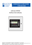
2.3.1
RAM/EPROM Select Headers (J1—J4)
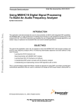
The top of Figure 2-2 shows the factory configuration of jumper headers J1
through J4. The fabricated jumpers between pins 1 and 2 and pins 4 and 5, of
headers J1 and J4 configure the EVB for RAM devices at locations U2 and U4. If
headers J1 and J4 are configured in this way, the jumper configuration of headers
J2 and J3 does not matter (That is, fabricated jumpers may be absent from or in
any position of headers J2 and J3.)
Freescale Semiconductor, Inc...
To use type 27C256 EPROM devices at locations U2 and U4 (instead of RAMs),
reposition the fabricated jumpers of headers J1 and J4 between pins 2 and 3, and
between pins 5 and 6. Additionally, install fabricated jumpers between pins 1 and
2 of both jumper header J2 and jumper header J3. The middle of Figure 2-2 shows
this configuration.
To use type 27C512 EPROM devices at locations U2 and U4 (instead of either
RAMs or 27C256 EPROMs), reposition the fabricated jumpers of headers J1 and
J4 between pins 2 and 3, and between pins 5 and 6. Additionally, install fabricated
jumpers between pins 2 and 3 of both jumper header J2 and jumper header J3.
The bottom of Figure 2-2 shows this configuration.
NOTES
The factory-supplied RAMS at locations U2 and U4 are for use
only as pseudo ROM. Place variable storage and stack areas in
internal RAM or in RAMs at locations U1 and U3.
Make sure that the devices at locations U2 and U4 are identical:
both RAM, both type 27C256 EPROMs, or both type 27C512
EPROMs.
2-4
M68HC16Z1EVB/D — Rev 1
For More Information On This Product,
Go to: www.freescale.com
Freescale Semiconductor, Inc.
HARDWARE PREPARATION AND INSTALLATION
J1
1
2
27C512
27C256
3
J2
U2
RAM
U2
U2
EPROM
4
5
1
J3
6
J4
1
2
3
U4
EPROM
U4
RAM
U4
4
5
6
2
3
FABRICATED JUMPERS
Freescale Semiconductor, Inc...
CONFIGURATION FOR RAMS (FACTORY CONFIGURATION)
J1
1
2
27C512
27C256
3
J2
U2
RAM
U2
EPROM
5
1
U2
U4
RAM
1
J3
4
J4
U4
EPROM
U4
6
4
5
6
1
2
3
FABRICATED
JUMPERS
CONFIGURATION FOR 27C256 EPROMS
J1
1
2
3
U2
RAM
27C256
27C512
J2
U2
U2
EPROM
4
5
U4
EPROM
U4
RAM
1
J3
6
J4
U4
4
5
6
FABRICATED
JUMPERS
CONFIGURATION FOR 27C512 EPROMS
Figure 2-2. RAM/EPROM Select Header Configurations
M68HC16Z1EVB/D — Rev 1
For More Information On This Product,
Go to: www.freescale.com
2-5
Freescale Semiconductor, Inc.
HARDWARE PREPARATION AND INSTALLATION
2.3.2
Memory Devices (U1-U4) and Byte/Word Select Header (J5)
Board locations U1 through U4 are the EVB memory array. Locations U1 and U3
are for RAM devices, and locations U2 and U4 are for either RAM or EPROM
devices (as paragraph 2.3.1 explains). The sockets of all four devices accept
memory devices of two widths: either 0.300 mil or 0.600 mil DIP devices.
Freescale Semiconductor, Inc...
The U1 and U2 sockets have three rows of holes. To use a narrow device at U1 or
U2 insert the device into the left two rows of socket holes To use a wide device at
U1 or 02, insert the device into the outer two rows of holes.
In addition to accommodating either narrow or wide devices, the U3 and U4
sockets permit memory configuration as either byte or word addressable. To
handle this byte mode or word mode, these sockets have six rows of holes. To
configure a narrow memory device at location U3 or U4 for byte mode, insert the
device into rows 1 and 3 (the A position). To configure a narrow memory device
at location U3 or U4 for word mode, insert the device into rows 2 and 4 (the B
position). A wide device follows the same pattern: socket-hole rows 1 and 5 (byte
mode, A position) or rows 2 and 6 (word mode, B position). Printing on the EVB
guides device placement.
Jumper header J5 must be configured correctly for the memory device at location
U4. Header J5 selects the top address lines of the U4 memory device. Fabricated
jumpers between pins 1 and 2, and 4 and 5, as the drawing below shows, is correct
for a U4 memory device in word-mode position.
J5
1
2
3
U4
BYTE
U4
WORD
4
5
6
If the U4 device is in the byte-mode position reposition the U5 jumpers to pins 2
and 3, and 5 and 6.
Note that jumper headers J3 and J4 also affect address and control signals for the
device at location U4. Header J3 selects the signal on pin 1 of the memory only if
header J4 is configured for EPROM. Header J4 selects the signal for pins l and 27
of the memory.
2-6
M68HC16Z1EVB/D — Rev 1
For More Information On This Product,
Go to: www.freescale.com
Freescale Semiconductor, Inc.
HARDWARE PREPARATION AND INSTALLATION
Freescale Semiconductor, Inc...
As an example, consider a 27C512 EPROM, 64K x 8, installed at location U4.
This device requires 16 address lines. If the device is in the byte-mode position,
the U4 socket directly provides lines A0 through A13. Jumper header J5, set to
byte, passes line A14 to header J4 and line A15 to header J3. Header J3, set to
27C512, passes line A15 to header J4. Header J4 set to EPROM, passes lines A14
and A15 to the memory device. This completes the 16 address lines (A0—A15)
that the device needs.
If the 27C512 EFROM device is in the word-mode position, the U4 socket
directly provides address lines Al through A14. Jumper header J5, set to word,
passes line A15 to header J4 and line Al6 to header J3. Header J3, set to 27C512,
passes line A16 to header J4. Header J4, set to EPROM, passes lines A15 and
A16 to the memory device. This completes the 16 address lines (A1—A16) that
the device needs.
Tables 2-1 and 2-2 list pin signals and data bus sizes, respectively, for different
configurations of the EVB memory array.
NOTES
Although the EVB provides proper byte- or word-mode signals to
memory devices, the EVB does not select the data port size. The
default data-port size at power-up is 16 bits for the CSBOOT
pseudo-ROM control signal. At device reset, an internal pull-up of
the data-0 (D0) signal again sets the data port size to 16 bits To
select an 8-bit data-port size, the user must pull the D0 signal low
at device reset.
The data HAM. at locations U1 and U3, uses chip selects. The user
can program these chip selects for proper data bus sizing.
M68HC16Z1EVB/D — Rev 1
For More Information On This Product,
Go to: www.freescale.com
2-7
Freescale Semiconductor, Inc.
HARDWARE PREPARATION AND INSTALLATION
Table 2-1. Memory Device Pin Signals
Freescale Semiconductor, Inc...
Device and
Configuration
Data
Signals
Available
Address
Signals
Chip
Select
Write
Enable
Pseudo ROM
U2
U4-A (byte)
U4-B (word)
D0–D7
D8–D15
D8–D15
A1–A16
A0–A15
A1–A16
CSBOOT
CSBOOT
CSBOOT
R/W*
R/W*
R/W*
DATA RAM
U1
U3-A (byte)
U3-B (word)
D0–D7
D8–D15
D8–D15
A1–A16
A0–A15
A1–A16
CS2*
CS2*
CS2*
CS1*
CS0*
CS0*
Table 2-2. Memory Device Pin Signals
Word — 16 Bits
Device and
Configuration
Word
Memory
Access
Byte
Memory
Access
Byte — 8 Bits
Word
Memory
Access
Byte
Memory
Access
Pseudo ROM
U2
U4-A (byte)
U4-B (word)
Read, write
N/A
Read, write
Read(1)
N/A
Read(1)
N/A
Read, write
N/A
N/A
Read, write
N/A
DATA RAM
U1
U3-A (byte)
U3-B (word)
Read, write
N/A
Read, write
Read, write(2)
N/A
Read, write(2)
N/A
Read, write
N/A
N/A
Read, write
N/A
(1) For a byte write, the HC16 places the data byte on both halves of the data bus This
writes a word into the pseudo RQM memories, possibly causing an unexpected
error.
(2) To accomplish this, program the chip selects before accessing memory.
2-8
M68HC16Z1EVB/D — Rev 1
For More Information On This Product,
Go to: www.freescale.com
Freescale Semiconductor, Inc.
HARDWARE PREPARATION AND INSTALLATION
2.3.3
P1, P2 +5-Volt Select Header (J6)
The cut-trace short of jumper header 36. below, gives +5-volt power to pins 1 of
logic analyzer connectors P1 and P2.
Freescale Semiconductor, Inc...
J6
CUT-TRACE SHORT (ON
BOTTOM OF BOARD)
If you do not want this functionality, carefully cut the J6 trace, on the bottom of
the board. Subsequently, to restore the power to pins 1 of P1 and P2, insert a
fabricated jumper in header J6.
2.3.4
Memory Access Fault Prevention Header (J7)
The factory configuration of jumper header J7 is shown below. The fabricated
jumper installed between pins 2 and 3 ensures correct MCU operation at power-up
by asserting the DSACK0 signal. (This asserted signal puts the MCU into
background mode, should RAM reset vectors point to unimplemented memory.)
J7
1
BERR
2
3
DSACK0
Repositioning the fabricated jumper to pins 1 and 2 asserts the BERR signal. (For
future revisions of the HC16Z1, this will be an alternative way to ensure correct
operation by putting the MCU into background mode.)
M68HC16Z1EVB/D — Rev 1
For More Information On This Product,
Go to: www.freescale.com
2-9
Freescale Semiconductor, Inc.
HARDWARE PREPARATION AND INSTALLATION
2.3.5
P5, P6 +5-Volt Select Header (J8)
The cut-trace short of jumper header J8, below, gives +5-volt power to pins 1 of
logic analyzer connectors P5 and P6.
Freescale Semiconductor, Inc...
J8
CUT-TRACE SHORT (ON
BOTTOM OF BOARD)
If you do not want this functionality carefully cut the J8 trace on the bottom of the
board. Subsequently, to restore the power to pins 1 of P5 and P6, insert a
fabricated jumper in header J8
2.3.6
RXD Connect Header (J9)
The cut-trace snort of jumper header J9, below, connects the RXD signal of the
HC16 device to the RS-232 driver device at location U8.
J9
CUT-TRACE SHORT (ON
BOTTOM OF BOARD)
To disconnect the RXD signal from the U8 device, carefully cut the J9 trace, on
the bottom of the board. Subsequently, to reconnect the RXD signal, insert a
fabricated jumper in header J9.
2-10
M68HC16Z1EVB/D — Rev 1
For More Information On This Product,
Go to: www.freescale.com
Freescale Semiconductor, Inc.
HARDWARE PREPARATION AND INSTALLATION
2.3.7
TXD Connect Header (J10)
The cut-trace short of jumper header J10, below, connects the TXD signal of the
HC16 device to the RS-232 driver device at board location U8.
Freescale Semiconductor, Inc...
J10
CUT-TRACE SHORT (ON
BOTTOM OF BOARD)
To disconnect the TXD signal from the U8 device, carefully cut the J10 trace, on
the bottom of the board. Subsequently, to reconnect the TXD signal, insert a
fabricated jumper in header J10.
2.3.8
Clock Select Headers (J11, J12, J14)
The cut-trace shorts of jumper headers J11 and J14, and no fabricated jumper in
jumper header J12, select the on-board crystal clock source. (This 32 kHz crystal
provides for 16.78 MHz bus operation.)
J11
1
2
J12
1
2
1
J14
2
CUT-TRACE SHORT (ON
BOTTOM OF BOARD)
To use an external clock source instead, carefully cut the J11 and J14 traces, on
the bottom of the board, and insert a fabricated jumper in header J12. Apply the
external clock signal to pin 1 of header J11. The frequency of the external cock
signal can be from 25 to 50 kHz.
Subsequently, to reinstate the on-board crystal clock source, remove the external
clock signal from header J11, remove the fabricated jumper from header J12, and
insert fabricated jumpers in headers J11 and J14.
M68HC16Z1EVB/D — Rev 1
For More Information On This Product,
Go to: www.freescale.com
2-11
Freescale Semiconductor, Inc.
HARDWARE PREPARATION AND INSTALLATION
2.3.9
Factory Test Header (J13)
If a jumper header is at board location J13, it is for factory use, there may be no
jumper header at all. Do not use a fabricated jumper or make any other
connections at board location J13.
Freescale Semiconductor, Inc...
J13
CUT-TRACE SHORT (ON
BOTTOM OF BOARD)
CAUTION
Do not change the factory configuration of board location J13. In
particular, do not apply external power to pin 1 of location J13;
doing so could cause damage to the external power supply.
2.3.10 D/A Select Headers (J15—J17)
The factory configuration of jumper headers J15 through J17 is no fabricated
jumpers, as shown below. This is correct when there is no D/A data conversion.
J15
J16
J17
For optional D/A data conversion via a user-supplied PCM56P device in EVB
location U12, install fabricated jumpers in headers J15, J16, and J17. (These
jumpers connect the SCK PCS/SS*, and MOSI lines, respectively.)
If a PCM56P device is installed at location U12, removing the jumpers from
headers J15 through J17 removes the PCM56P device from the EVB circuitry.
2-12
M68HC16Z1EVB/D — Rev 1
For More Information On This Product,
Go to: www.freescale.com
Freescale Semiconductor, Inc.
HARDWARE PREPARATION AND INSTALLATION
2.4 INSTALLATION INSTRUCTIONS
The EVB is designed for table-top operation. A user-supplied power supply and
host computer are required. The computer must have a Centronics-compatible
parallel port, and must run MS-DOS.
The following paragraphs explain EVB connections.
Freescale Semiconductor, Inc...
2.4.1
Power Supply—EVB Connection (P8)
The EVB requires a +5 Vdc @ 1.0 Amp power supply for basic operation. Use
connector P8 to connect this system power to the EVB. Contact 1 is GND; black
lever. Contact 2 is VDD (+5 Vdc); red lever. Use 20 or 22 AWG wire for power
connections. For each wire, trim back the insulation 1/4 in. (.635 cm), lift the
appropriate lever of P8 to release tension on the contacts, then insert the bare wire
into P8 and close the lever.
CAUTION
Do not use wire larger than 20 AWG in connector P8. Such wire
could damage the connector.
NOTE
(D/A conversion, via an optional Burr-Brown PCM56P device,
requires a user-supplied connector at location P11. This connector
location accommodates user-supplied power of -7 Vdc or less.)
2.4.2
Computer—PC Printer Port Connection (P9)
Connect the EVB to the host computer via a user-supplied 25-conductor cable
assembly. One end of the cable assembly needs a female DB25 connector; this
end of the cable connects to the EVB PC printer port (connector P9). The other
end of the cable assembly needs a male DB25 connector; this end of the cable
connects to the Centronics-compatible port of the computer. For connector pin
assignments and signal descriptions of connector P9, refer to Chapter 6.
M68HC16Z1EVB/D — Rev 1
For More Information On This Product,
Go to: www.freescale.com
2-13
Freescale Semiconductor, Inc.
HARDWARE PREPARATION AND INSTALLATION
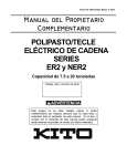
2.4.3
Computer—User Interface Port Connection (P10)
Freescale Semiconductor, Inc...
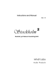
Connection of an RS-232C compatible terminal or host computer to the EVB
requires a user-supplied 25-conductor cable assembly. One end of the cable
assembly needs a male DB25 connector; this end of the cable connects to the EVB
user interface port (connector P10), shown below. The other end of the cable
assembly needs the appropriate connector for the RS-232C compatible port of the
terminal or host computer. For connector pin assignments and signal descriptions
of connector P10, refer to Chapter 6.
NOTE
This cable is not essential for proper operation of the EVB. Use
this cable and connector P10 only if RS-232C communication with
the on-chip SCI port is required.
P10
GND 1
TXD 2
RXD 3
RTS 4
CTS 5
DSR 6
SIGNAL GND 7
DCD 8
NC 9
NC 10
NC 11
NC 12
NC 13
14 NC
15
16
17
18
19
NC
NC
NC
NC
NC
20
21
22
23
24
25
NC
NC
NC
NC
NC
NC
EVB User Interface Port (Connector P10)
2-14
M68HC16Z1EVB/D — Rev 1
For More Information On This Product,
Go to: www.freescale.com
Freescale Semiconductor, Inc.
HARDWARE PREPARATION AND INSTALLATION
The EVB is wired as data communication equipment (DCE) whereas a terminal
and most serial modem ports on host computers are wired as data terminal
equipment (DTE). This lets a straight-through cable be used for most setups.
If a different type of cable is used for RS-232C connection between the EVB and
a host computer, a null modem adapter (shown below) may be required to match
the cable to the EVB terminal port connector.
Freescale Semiconductor, Inc...
A null modem adapter reverses the roles of various data and control signals to
make a DTE device appear as a DCE device, or vice versa.
DB-25S
DB-25P
GND
1
1
GND
TXD
2
2
TXD
RXD
3
3
RXD
RTS
4
4
RTS
CTS
5
5
CTS
DSR
6
SIGNAL GND
7
7
SIGNAL GND
DCD
8
8
DCD
20
DTR
Connector P10 Null Modem Adapter
M68HC16Z1EVB/D — Rev 1
For More Information On This Product,
Go to: www.freescale.com
2-15
Freescale Semiconductor, Inc.
HARDWARE PREPARATION AND INSTALLATION
2.4.4
Logic Analyzer—EVB Connections (P1—P7)
Use logic analyzer connectors P1 through P7 to connect the EVB to the circuit
being evaluated. For signal descriptions, refer to chapter 6.
Freescale Semiconductor, Inc...
The EVB area of extra holes next to connectors P1 through P7 gives the user
space for 10-pin Berg-type strips. To use such strips, install them on the bottom of
the board, and solder the pins on the top. Wire-wrap from the bottom of the EVB
to the user wire-wrap area. Be sure to put standoffs in the corner mounting holes
to protect the wire-wrapping on the bottom of the EVB.
P1
+5V
1
DSACK1
3
A14
5
A12
7
A10
9
A8 11
A6 13
A4 15
A2 17
A0 19
•
•
•
•
•
•
•
•
•
•
•
•
•
•
•
•
•
•
•
•
P2
2
SPARE
+5V
1
4
A15
AS
3
6
A13
D14
5
8
A11
D12
7
D10
9
10 A9
12 A7
D8 11
14 A5
D6 13
16 A3
D4 15
18 A1
D2 17
20 GND
D0 19
P3
SPARE
1
DSACK0
3
HALT
5
DS
7
BG/CS1
9
CLKOUT 11
A22/CS9 13
A20/CS7 15
A18 17
A16 19
2-16
•
•
•
•
•
•
•
•
•
•
•
•
•
•
•
•
•
•
•
•
•
•
•
•
•
•
•
•
•
•
•
•
•
•
•
•
•
•
•
•
2
SPARE
4
D15
6
D13
8
D11
10 D9
12 D7
14 D5
16 D3
18 D1
20 GND
P4
2
SPARE
SPARE
1
4
AVEC
SPARE
3
6
AS
8
BR/CS0
10 CSBOOT
TSTME/TSC
5
RXD
7
PWMB
9
12 A23/CS10
PAI 11
14 A21/CS8
OC4 13
16 A19/CS6
OC2 15
18 A17
IC3 17
20 GND
IC1 19
•
•
•
•
•
•
•
•
•
•
•
•
•
•
•
•
•
•
•
•
2
SPARE
4
SPARE
6
RESET
8
PCLK
10 PWMA
12 IC4/OC5
14 OC3
16 OC1
18 IC2
20 GND
M68HC16Z1EVB/D — Rev 1
For More Information On This Product,
Go to: www.freescale.com
Freescale Semiconductor, Inc.
HARDWARE PREPARATION AND INSTALLATION
P5
+5V
1
CLKOUT
3
BKPT/DSCLK
5
IPIPE0 LATCHED
7
IPIPE0/DSO
9
DSACK1 11
FC2/CS2 13
Freescale Semiconductor, Inc...
FC0/CS3 15
SIZ0 17
BGACK/CS2 19
•
•
•
•
•
•
•
•
•
•
•
•
•
•
•
•
•
•
•
•
P6
2
SPARE
4
BERR
+5V
1
DS
3
6
8
FREEZE
IRQ1
5
IPIPE1 LATCHED
IRQ3
7
10 IPIPE1/DSI
IRQ5
9
12 DSACK0
IRQ7 11
14 FC1/CS4
PCS0/SS 13
16 SIZ1
PCS2 15
18 R/W
SCK 17
20 GND
MOSI 19
•
•
•
•
•
•
•
•
•
•
•
•
•
•
•
•
•
•
•
•
2
SPARE
4
MODCK
6
IRQ2
8
IRQ4
10 IRQ6
12 TXD
14 PCS1
16 PCS3
18 MISO
20 GND
P7
SPARE
1
VRHP
3
AD6
5
AD4
7
AD2
9
AD0 11
AN+ 13
DAC2OUT 15
SPARE 17
AGND 19
•
•
•
•
•
•
•
•
•
•
•
•
•
•
•
•
•
•
•
•
M68HC16Z1EVB/D — Rev 1
2
SPARE
4
VRLP
6
AD7
8
AD5
10 AD3
12 AD1
14 AN16 DAC1OUT
18 SPARE
20 AGND
For More Information On This Product,
Go to: www.freescale.com
2-17
Freescale Semiconductor, Inc.
Freescale Semiconductor, Inc...
HARDWARE PREPARATION AND INSTALLATION
2-18
M68HC16Z1EVB/D — Rev 1
For More Information On This Product,
Go to: www.freescale.com
Freescale Semiconductor, Inc.
EVB16 OPERATING PROCEDURE
CHAPTER 3
EVB16 OPERATING PROCEDURE
Freescale Semiconductor, Inc...
3.1 INTRODUCTION
This chapter explains how to start and use EVB16. The explanations of this
chapter cover startup, general use, the main screen, debug commands, source code
debugging, and the trace buffer.
3.1.1
Typeface and Parameter Conventions
This chapter uses four different typefaces:
1. Chapter heads, chapter subheads, and EVB16 commands appear in
this bold typeface. Heads and subheads start at the far left margin;
commands are indented about half an inch.
2. Examples are in this typeface.
3. Text and explanations are in this normal typeface.
4. Special comments are in this italic typeface.
Also, note these conventions for parameters and keyboard entries:
• add indicates any valid, hexadecimal address or label.
• file indicates a file name.
• IP is the instruction pointer, which points to the next instruction to be
executed.
• n indicates any hexadecimal number, 0—0FFFFF.
• PC is the program counter, which points to the next instruction to be
fetched. (The PC value equals the IP value plus 6.)
• [ ] indicate an optional parameter.
• <CR> indicates the ENTER, RETURN, or carriage-return key of your
keyboard.
M68HC16Z1EVB/D — Rev 1
For More Information On This Product,
Go to: www.freescale.com
3-1
Freescale Semiconductor, Inc.
EVB16 OPERATING PROCEDURE
3.1.2
EVB16 Numerical Formats
Unless otherwise specified, all numbers in EVB16 are hexadecimal: all numerical
values EVB16 displays have base 16. Furthermore, EVB16 presumes that any
numbers you enter also are base-16 numbers.
However, EVB16 does accommodate decimal, octal, and binary numbers, as long
as the numbers have a proper prefix or suffix, per Table 3-1.
Freescale Semiconductor, Inc...
Table 3-1. EVB16 Number Symbols
Symbol
3-2
Meaning
$
Optional prefix for hexadecimal numbers, as $0FF
!
Required prefix for decimal numbers, as !255 (which equals $0FF)
@
Required prefix for octal numbers, as @377 (which equals $0FF and
!255)
%
Required prefix for binary numbers, as %11111111 (which equals
$0FF, !255, and @377)
H
Optional hexadecimal-number suffix; an alternative to the $ prefix
(0FFH = $0FF)
T
Decimal-number suffix; an alternative to the ! prefix (255T = !255)
O
Octal-number suffix; an alternative to the @ prefix (377O = @377)
Q
Binary-number suffix; an alternative to the % prefix (11111111Q =
%11111111)
M68HC16Z1EVB/D — Rev 1
For More Information On This Product,
Go to: www.freescale.com
Freescale Semiconductor, Inc.
EVB16 OPERATING PROCEDURE
3.2 STARTUP
Before running EVB16 software, make sure that the EVB board is connected and
powered up. To start EVB16 operation, enter the startup command at the DOS
prompt:
Freescale Semiconductor, Inc...
EVB16 [<lptn>] [<path>] [bw]
<lptn>
Specifies the parallel port connected to the EVB. Possible
values are lpt1, lpt2, and lpt3; lpt1 is the default. (The
values lpt1, lpt2, and lpt3 also are valid commands from
within EVB16.)
<path>
Specifies the full path to a directory that contains the code
for source-level debugging.
bw
Specifies black-and-white mode (often appropriate for
using a lap-top computer).
EVB16 lpt2 path
EVB16 bw
M68HC16Z1EVB/D — Rev 1
Starts program via lpt2 and points the way to the
code to be debugged.
Starts program, specifies black-and-whitemode.
For More Information On This Product,
Go to: www.freescale.com
3-3
Freescale Semiconductor, Inc.
EVB16 OPERATING PROCEDURE
3.3 MAIN SCREEN
Freescale Semiconductor, Inc...
Figure 3-1 shows the main screen, which consists of seven windows: the CPU
window, the instruction pointer (IP) window, the breakpoint (BR) window, the
code window, the program (F6) memory window, the data (F3) memory window,
and the debug (F1) window.
3.3.1
CPU Window
The CPU window, at the upper left of the main screen, shows the status of CPU
resources. Use the debug window to change any register value in the CPU
window: enter the resource, a space, and the new value. To change the value of
the AM register, you must specify the high-order 20 bits (AMH) or the low-order
16 bits (AML). You may change individual bits in the condition code register by
specifying the bit and entering the value (0 or 1).
3-4
M68HC16Z1EVB/D — Rev 1
For More Information On This Product,
Go to: www.freescale.com
Freescale Semiconductor, Inc.
EVB16 OPERATING PROCEDURE
3.3.2
Instruction Pointer (IP) Window
The IP window, at the top center of the main screen, shows the value of the
instruction pointer, which the EVB16 software uses to designate the instruction to
be executed next. Note that the IP value always is six bytes less than the program
counter (PC) value. Use the debug window to change the IP value: enter IP, a
space, and the new value .
Freescale Semiconductor, Inc...
NOTE
The IP is not a CPU resource, because it does not exist in the part.
3.3.3
Breakpoint (BR) Window
The BR window, below the IP window, lists the addresses of active breakpoints.
As many as seven breakpoints may be active at once; their addresses are not in
any particular order in the BR window. Use the debug window to add a
breakpoint: enter BR, a space, and the new address value. To remove a
breakpoint, make the same entry, but enter an address value from the BR window.
To remove all breakpoints, enter NOBR in the debug window.
Using the GOTIL or STEPTIL command creates a temporary breakpoint not
indicated in the BR window.
3.3.4
Code Window
The code window displays code in one of three ways. If no map file has been
loaded, the code window displays disassembled code. If a full map file has been
loaded, there are two possibilities: the code window either displays source code,
or it displays disassembled code with labels defined in the map file. When
appropriate, this window also shows the IP and PC values, as well as addresses of
active breakpoints. The EVB16 software also uses the code window to display the
trace buffer.
Paragraph 3.6 explains source-code debugging via the code window.
M68HC16Z1EVB/D — Rev 1
For More Information On This Product,
Go to: www.freescale.com
3-5
Freescale Semiconductor, Inc.
EVB16 OPERATING PROCEDURE
3.3.5
Memory Windows
The F6 and F3 memory windows, at the center of the main screen, display
memory contents. The F6 window accesses program memory. The F3 window
accesses data memory.
Freescale Semiconductor, Inc...
Values in these windows are hexadecimal and, when appropriate, in seven-bit
ASCII symbols. A period appears in lieu of an unprintable ASCII character.
3.3.6
Debug Window
The debug window, at the bottom of the main screen, accepts most of your
commands. The prompt symbol is the > character.
3.3.7
Window Function Keys
To move between windows, and to carry out certain other actions, use special
function (F) keys of the keyboard. Table 3-2 lists the functions of these keys.
Table 3-2. EVB16 Special Function Keys
F Key
3-6
Function
F1
Go to the debug window
F2
Go to the code window. In this window, you may scroll or see future
code.
F3
Go to the F3 memory window. In this window, you may scroll through
data memory.
F4
Do a single-step trace. (This key has the same role as the ST
command.)
F5
Shrink or enlarge the code window (if it displays source code).
F6
Go to the F6 memory window. In this window, you may scroll through
code memory.
F7
Go to the code window as a trace window. In this format of the code
window, you may scroll through the trace buffer.
F8
Shell to DOS.
F9
Repeat the last command.
F10
Activate the help window.
M68HC16Z1EVB/D — Rev 1
For More Information On This Product,
Go to: www.freescale.com
Freescale Semiconductor, Inc.
EVB16 OPERATING PROCEDURE
3.4 GENERAL USE
Do most of your debugging from the debug window. You may enter all debug
commands in this window. Typically, the first command a user enters is one of the
load commands. If you have created an object (.S19) file as well as a map (.MAP)
file via the MASM16 assembler shell, enter the LOADALL command:
>LOADALL
Brings your code and symbols into EVB16.
Freescale Semiconductor, Inc...
Filename:
In response to the filename prompt, enter the name of the file. Next, if you
have loaded appropriate reset vectors for the code, enter a reset command;
this resets the hardware and initializes the IP and PC correctly.
>RESET
Resets the hardware.
The code window shows your code, either via disassembly or via your
actual source. At this point, you may start debugging. To have the F3 or F6
memory windows display code starting at a useful address, enter the
SHOWF3 (or SHOWF6) command:
>SHOWF3 myarray
Sets location myarray as the start of the F3 window display.
Now you may begin debugging and testing your code, by setting
breakpoints or single-stepping. For example, to single-step, enter this
command:
>ST 50
M68HC16Z1EVB/D — Rev 1
Single-step through $50 instructions.
For More Information On This Product,
Go to: www.freescale.com
3-7
Freescale Semiconductor, Inc.
EVB16 OPERATING PROCEDURE
3.5 DEBUG WINDOW COMMANDS
Table 3-3 lists EVB16 debug commands. Explanations of the individual
commands follow the table.
Table 3-3. Debug Window Commands
Freescale Semiconductor, Inc...
Syntax
3-8
Meaning
ASM [add]
Assemble into pseudo ROM
BF add add n
Block fill memory with data
BR add
Set or remove breakpoint
BW
Change display to black-and-white mode
CLEARMAP
Remove source-level debug information
CODE add
Show disassembled code in code window
DMM[.X] add [n]
Assign data to RAM
EVAL n [op] [n]
Evaluate expression
EXIT
Exit the program
FILL add add n
Block fill memory with data
G [add] [add]
Go (execute program)
GO [add] [add]
Go (execute program)
GOTIL add
Go from IP to add
GOTILROM add
Single-step fast to add
HELP
Display help system
LOAD
Load S-records
LOADALL
Load S-records and debug file
LOADMAP
Load MASM debug file
LPT[x]
Specify printer port
MDF3 add
Set F3 window memory display
MDF6 add
Set F6 window memory display
NOBR
Remove all breakpoints
M68HC16Z1EVB/D — Rev 1
For More Information On This Product,
Go to: www.freescale.com
Freescale Semiconductor, Inc.
EVB16 OPERATING PROCEDURE
Table 3-3. Debug Window Commands (continued)
Freescale Semiconductor, Inc...
Syntax
Meaning
PMM[.X] add [n]
Modify memory in program space
QUIT
Exit the program
RESET
Do a hardware reset
SHOWF3 add
Set F3 window memory display
SHOWF6 add
Set F6 window memory display
SIGNLATCH n
Set sign latch to n
SOURCE
Toggle code display
SOURCEPATH
Search for code in another directory
ST [n]
Do single-step trace
STEP [n]
Do single-step trace
STEPFOR
Do single-step trace until breakpoint
STEPTIL add
Do single-step until add
SYMBOL chars val
Add symbol to loaded map file
T [n]
Do single-step trace
TRACE [add] [add]
Execute trace
VERIFY
Compare file to memory
WATCHDOG
Disable watchdog timer
WHEREIS symbol
Show symbol value
M68HC16Z1EVB/D — Rev 1
For More Information On This Product,
Go to: www.freescale.com
3-9
Freescale Semiconductor, Inc.
EVB16 OPERATING PROCEDURE
ASM [add]
Assemble into pseudo ROM
add
Starting address or label for assembly.
Freescale Semiconductor, Inc...
This command invokes the one-line assembler, starting at the specified address. If
this command does not include an address, assembly starts at the address used by
the previous ASM command.
This assembler assembles user code, including labels, provided that the labels are
in a previously loaded map file. If no map file is loaded, labels may not be used.
The ASM command does not define labels. Your entry must start with an opcode.
During assembly, EVB shows the instruction at the current location in the debug
window. To modify this instruction, type in a new one. To end the assembly
session, type a period (.) at the prompt. To advance to the next location without
changing the present location, enter a carriage return.
You may press the F10 (help) key to see the format of assembly-language
instructions.
>ASM 10500
Start assembly at location $10500.
10500 274c nop >
Shows disassembly, prompts for input.
BF add add n
Block fill memory with data
add
n
First parameter: fill operation lower limit; second parameter: fill
operation upper limit.
Fill pattern.
This command repeats a specific byte value throughout a specified user memory
range. An invalid address leads to an error message. You may use this command
at the beginning of a debug session to initialize an area of memory or an array.
3-10
>BF C000 C030 FF
Assign value $FF to each byte, $C000—$C030.
>BF C000 C000 0
Assign value 0 to location $C000.
M68HC16Z1EVB/D — Rev 1
For More Information On This Product,
Go to: www.freescale.com
Freescale Semiconductor, Inc.
EVB16 OPERATING PROCEDURE
BR add
Set or remove breakpoint
add
Address or label of breakpoint to be set or removed.
Freescale Semiconductor, Inc...
This command sets or removes the specified address in the breakpoint address
table (shown in the BR window). Seven breakpoints may be active at any time.
Program execution halts at any instruction whose address is in the breakpoint
address table. The order of breakpoints in the BR window has no effect on their
operation.
For a temporary, additional breakpoint in RAM or pseudo ROM, use the GOTIL
or STEPTIL command. For such a breakpoint in ROM, use the GOTILROM
command.
>BR 200
Set breakpoint at address $200.
>BR start1
Set breakpoint at label start1.
BW
Change display to black-and-white mode
This command puts the display in black-and-white mode. Use this command if the
default color display is hard to read, for example, if you use a lap-top computer.
You also may use this command at the command line that starts the program. This
action may be taken only once, following a hardware reset. There is no command
to return to color mode.
Put display in black-and-white mode.
>BW
CLEARMAP
Remove source-level debug information
This command clears the previously loaded map file from EVB16 software. This
eliminates symbols and eliminates source code debugging. The code window
defaults to simple disassembly.
>CLEARMAP
M68HC16Z1EVB/D — Rev 1
Delete the current map information.
For More Information On This Product,
Go to: www.freescale.com
3-11
Freescale Semiconductor, Inc.
EVB16 OPERATING PROCEDURE
CODE add
Show disassembled code in code window
add
Starting address or label for disassembled code.
Freescale Semiconductor, Inc...
This command is an alternative to scrolling in the code window. After execution
of any instruction, the code window reverts to showing IP and PC values.
>CODE 10300
Show code starting at address $10300.
>CODE sub1
Show code starting at label sub1.
DMM[.X] add [n] ... [n]
.X
add
n
Assign data to RAM
RAM units: .B = bytes, .W = words, and .L = long words.
RAM address or label to receive data value.
Data to be entered.
This command writes the specified data into RAM at the specified address.
Consecutive data values (separated by spaces) go into consecutive memory units
defined by the .X parameter. (The default memory unit is the byte.)
If the command line does not specify data, the software prompts for data, one
memory unit at a time. Such prompts include the memory location and current
value. To change the value, enter the new value. To advance to the next location
without changing the present location, press <CR>. To exit this command, enter a
period or other nonsense value.
3-12
>DMM 100 1 2 3 4
Put values 1—4 into locations $100—$103.
>DMM[.B] 200
Start interactive memory modification, in bytes.
200 = 41 >
Shows current value, prompts for new one.
M68HC16Z1EVB/D — Rev 1
For More Information On This Product,
Go to: www.freescale.com
Freescale Semiconductor, Inc.
EVB16 OPERATING PROCEDURE
EVAL n [op] [n]
Evaluate expression
n
Freescale Semiconductor, Inc...
op
First parameter: Expression or first term to be evaluated; third
parameter: second term to be evaluated.
Operator.
This command evaluates an arithmetic expression, giving the result in
hexadecimal, decimal, octal, and binary values. The expression can contain the
operators for addition, subtraction, multiplication, and division (+, –, *, and / ).
Single spaces must separate parameter values.
>EVAL 102T + 54
Evaluate !102 plus $54.
Answer in four bases.
00BAH 186T 000272O 0000000010111010Q
EXIT
Exit the program
This command exits the program, returning to DOS.
>EXIT
FILL add add n
Return to DOS.
Block fill memory with data
This command is an alternative form of the BF command.
M68HC16Z1EVB/D — Rev 1
For More Information On This Product,
Go to: www.freescale.com
3-13
Freescale Semiconductor, Inc.
EVB16 OPERATING PROCEDURE
G [add] [add]
Go (execute program)
add
First parameter: execution starting address or label; second parameter:
breakpoint address or label.
This command starts and stops processor execution of instructions according to
the specified address parameters:
Freescale Semiconductor, Inc...
• If the command has two parameter values, the system sets a new breakpoint
at the second address or label, then executes code from the first address or
label. Execution continues until it arrives at a breakpoint (which could be
the one just set) or until the user presses a key.
• If the command has one parameter value, the system executes code from
that address or label until it arrives at an existing breakpoint, or until the
user presses a key.
• If the command has no parameter values, the system executes code from the
IP value until it arrives at an existing breakpoint, or until the user presses a
key.
The processor runs at full execution speed during a GO command.
NOTE
To terminate program execution started via the G command, press
the F1 key.
>G start time1
Start code execution at label start; break at label
time1.
>G 1050
Start code execution at address $1050.
>G start
Start code execution at label start.
>G
Start code execution at IP value.
GO [add] [add]
Go (execute program)
This command is an alternative form of the G command.
3-14
M68HC16Z1EVB/D — Rev 1
For More Information On This Product,
Go to: www.freescale.com
Freescale Semiconductor, Inc.
EVB16 OPERATING PROCEDURE
GOTIL add
Go from IP to add
add
Address or label of temporary breakpoint.
Freescale Semiconductor, Inc...
This command inserts a temporary breakpoint at the specified address and starts
execution of code at the IP value. Code execution stops when it reaches the
temporary breakpoint (or an existing breakpoint). This command works only with
program code in RAM or pseudo ROM. (To debug code in ROM, use the
GOTILROM command.)
The processor runs at full execution speed during a GOTIL command.
>GOTIL sub1
Execute code from IP value to label sub1.
>GOTIL 1055
Execute code from IP to address $1055.
GOTILROM add
add
Single-step fast to add
ROM address or label of temporary breakpoint.
This command starts rapid single-stepping through code, beginning at the IP
value. Single-stepping stops at the specified breakpoint address or label. This
command is the fastest way to reach a breakpoint in ROM. The processor does not
run at full execution speed during a GOTILROM command.
>GOTILROM sub1
Single-step through code from IP value to label
sub1.
>GOTILROM 1055
Execute code from IP to address $1055.
M68HC16Z1EVB/D — Rev 1
For More Information On This Product,
Go to: www.freescale.com
3-15
Freescale Semiconductor, Inc.
EVB16 OPERATING PROCEDURE
HELP
Display help system
Freescale Semiconductor, Inc...
This command, an alternative to F10, activates the help system. (The files
EVB16.HLP and EVB16.EXE must reside in the same directory for this command
to work.) The help system works via temporary pop-up windows. Once these
windows are activated, use these keys to:
arrow keys
move within a menu
ENTER
go to a chosen menu
ESC
go to a previous menu or exit
PgDn
go back one menu page
PgUp
go forward one menu page
Activate the help system.
>HELP
LOAD
Load S-records
This command loads object code into the EVB16. When you enter the LOAD
command, the system prompts for a file name. Enter the name of the file that
contains the object code. If the file is not in the current directory, enter the entire
DOS path. If you do not specify a file extension, the system assumes the extension
.S19. Note that this command only loads a file; it does not do a reset, nor does it
affect any CPU resources.
Load object code into the EVB16.
>LOAD
LOADALL
Load S-records and debug file
This command loads an object file and a debug map file at the same time. When
you enter the LOADALL command, the system prompts for a file name. If the
files are not in the current directory, enter the entire DOS path. The system
assumes the file extensions .S19 and .MAP. Note that this command only loads
the files; it does not do a reset, nor does it affect any CPU resources. (MASM16
creates map files during assembly, as Chapter 4 explains.)
>LOADALL
3-16
Load object code and map file.
M68HC16Z1EVB/D — Rev 1
For More Information On This Product,
Go to: www.freescale.com
Freescale Semiconductor, Inc.
EVB16 OPERATING PROCEDURE
LOADMAP
Load MASM debug file
Freescale Semiconductor, Inc...
This command loads a debug map file into the EVB16. When you enter the
LOADMAP command, the system prompts for a file name. Enter the name of the
file that contains the map file. If the file is not in the current directory, enter the
entire DOS path. If you do not specify a file extension, the system assumes the
extension .MAP. (MASM16 creates map files during assembly, as Chapter 4
explains.)
>LOADMAP
Load map file into the EVB16.
LPT[x]
Specify printer port
x
Number of printer port: 1, 2, or 3 (1 is the default).
This command specifies the DOS printer port to use.
>LPT2
Use printer port LPT2.
MDF3 add
Set F3 window memory display
add
Starting address or label for code in the window
This command resets the display of the F3 screen window to show code starting at
the specified address.
>MDF3 200
Start F3 window display with address $200.
>MDF3 myarray
Start F3 window display at label myarray.
MDF6 add
Set F6 window memory display
add
Starting address or label for code in the window
This command resets the display of the F6 screen window to show code starting at
the specified address.
>MDF6 8000
Start F6 window display with address $8000.
>MDF6 table
Start F6 window display at label table.
M68HC16Z1EVB/D — Rev 1
For More Information On This Product,
Go to: www.freescale.com
3-17
Freescale Semiconductor, Inc.
EVB16 OPERATING PROCEDURE
NOBR
Remove all breakpoints
This command removes all the addresses from the breakpoint address table
(shown in the BR window).
Remove all breakpoints.
>NOBR
Freescale Semiconductor, Inc...
PMM[.X] add [n] ... [n]
.X
add
n
Modify memory in program space
Program space units: .B = bytes, .W = words, and .L = long words.
Program space address or label to receive data value.
Data to be entered.
This command writes the specified data into program space at the specified
address. Consecutive data values (separated by spaces) go into consecutive units
defined by the .X parameter. (The default unit is the byte.)
If the command line does not specify data, the software prompts for data one unit
at a time. Such prompts include the memory location and current value. To change
the value, enter the new value. To advance to the next location without changing
the present location, press <CR>. To exit this command, enter a period or other
nonsense value.
>PMM 100 1 2 3 4
Put values 1—4 into locations $100—$103.
>PMM 200
Start interactive memory modification.
200 = 41 >
Shows current value, prompts for new one.
QUIT
Exit the program
This command is an alternative form of the EXIT command.
RESET
Do a hardware reset
This command does an EVB hardware reset to the reset vector address in the
68HC16 device.
>RESET
3-18
Reset hardware.
M68HC16Z1EVB/D — Rev 1
For More Information On This Product,
Go to: www.freescale.com
Freescale Semiconductor, Inc.
EVB16 OPERATING PROCEDURE
SHOWF3 add
Set F3 window memory display
This command is an alternative form of the MDF3 command.
SHOWF6 add
Set F6 window memory display
Freescale Semiconductor, Inc...
This command is an alternative form of the MDF6 command.
SIGNLATCH n
Set sign latch to n
n
New value (0 or 1) for sign latch.
This command gives the specified value to the sign latch CPU resource.
>SIGNLATCH 1
Set sign latch value to 1.
SOURCE
Toggle code display
This command toggles the display in the debug window between source code and
disassembled code. A valid map file must be loaded for this command to work.
>SOURCE
SOURCEPATH
Toggle debug window display to source code (or to
disassembled code).
Search for code in another directory
This command starts a search for source code not in the current directory. The
system prompts for the DOS path.
>SOURCEPATH
M68HC16Z1EVB/D — Rev 1
Search for code in another directory.
For More Information On This Product,
Go to: www.freescale.com
3-19
Freescale Semiconductor, Inc.
EVB16 OPERATING PROCEDURE
ST [n]
Do single-step trace
n
The number of steps to trace.
Freescale Semiconductor, Inc...
This command starts single-step tracing from the IP value for n number of steps.
The default n value is 1. The processor does not run at full execution speed during
an ST command.
>ST 10
Trace through 16 single steps.
>ST
Trace through 1 single step.
STEP [n]
Do single-step trace
This command is an alternative form of the ST command.
STEPFOR
Do single-step trace until breakpoint
This command begins continuous single-step tracing from the IP value. This
single-stepping continues until it arrives at a breakpoint, until there is an error
condition, or until the user presses a key. The processor does not run at full
execution speed during a STEPFOR command.
>STEPFOR
Single-step trace from IP until breakpoint.
STEPTIL add
Do single-step until add
add
The trace stopping address or label.
This command starts single-step tracing from the IP value to the specified address
or label. To stop such tracing, press any key.
>STEPTIL sub1
3-20
Single-step trace from IP to label sub1.
M68HC16Z1EVB/D — Rev 1
For More Information On This Product,
Go to: www.freescale.com
Freescale Semiconductor, Inc.
EVB16 OPERATING PROCEDURE
SYMBOL chars val
chars
val
Add symbol to loaded map file
ASCII characters of the new symbol label.
The new symbol value.
This command adds the specified label to the symbol table, giving it the specified
value. The symbol table contains as many as 30 user-defined labels.
Freescale Semiconductor, Inc...
>SYMBOL start 200
Defines the label start = $200.
T [n]
Do single-step trace
This command is an alternative form of the ST command.
TRACE [add] [add]
add
Execute trace
First parameter: execution starting address or label; second parameter:
breakpoint address or label.
This command starts and stops tracing according to the specified add parameters:
• If the command has two parameter values, the system sets a new breakpoint
at the second address or label, then traces code from the first address or
label. Tracing continues until it arrives at a breakpoint (which could be the
one just set) or until the user presses a key.
• If the command has one parameter value, the system traces code from that
address or label until it arrives at an existing breakpoint, or until the user
presses a key.
• If the command has no parameter values, the system traces code from the IP
value until it arrives at an existing breakpoint, or until the user presses a
key.
This command fills the trace buffer, so does not execute in real time.
>TRACE 200 1050
Start code trace at address $200; break at address
$1050.
>TRACE 1050
Start code trace at address $1050.
>TRACE start
Start code trace at label start.
>TRACE
Start code trace at IP value.
M68HC16Z1EVB/D — Rev 1
For More Information On This Product,
Go to: www.freescale.com
3-21
Freescale Semiconductor, Inc.
EVB16 OPERATING PROCEDURE
VERIFY
Compare file to memory
This command compares contents of a file with contents of EBV16 memory.
When you enter the VERIFY command, the system prompts for a file name. If the
file is not in the current directory, enter the entire DOS path. The compare action
ends when the system finds a difference between contents, or at the end of the file.
Freescale Semiconductor, Inc...
>VERIFY
Verify contents of file and memory.
WATCHDOG
Disable watchdog timer
This command disables the watchdog timer. This action may be taken only once,
following a hardware reset. (A reset enables the watchdog timer.)
>WATCHDOG
Disable watchdog timer.
WHEREIS symbol
symbol
Show symbol value
Label or address.
This command echoes a specified label and displays its address. Alternatively, this
command echoes a specified address and displays the label at that address.
3-22
>WHEREIS start
Show address of label start.
start = 200
System echoes label and shows address.
>WHEREIS 200
Show label at address $200.
start = 200
System echoes address and shows label.
M68HC16Z1EVB/D — Rev 1
For More Information On This Product,
Go to: www.freescale.com
Freescale Semiconductor, Inc.
EVB16 OPERATING PROCEDURE
3.6 SOURCE-LEVEL DEBUGGING
Loading a map file into the EVB via the LOADALL or LOADMAP command
enables source-level debugging. If the IP points to a code location, the code that
appears in the code window is your actual source code. (If no map file is loaded,
or if the IP points outside source code, the code window shows disassembled
code.)
Freescale Semiconductor, Inc...
MASM16 creates map files during assembly, as Chapter 4 explains.
The code window does not permit editing, but does let you set and remove
breakpoints. The PC and IP values are highlighted in the code window. To
maneuver within the code window, use the keys or key combinations of Table 3-4.
(Hold down the ALT key to see a list of code-window commands at the bottom of
the screen. When you release the ALT key, the bottom line reverts to its normal
display.)
Note that you may set breakpoints in any module. (In this context, module means
your main MASM16 source code or any include file.)
Even if the module in the code window has no breakpoints, the breakpoints
remain active in other modules. If a break occurs in another such module, the
module at breakpoint replaces the current module in the display.
NOTES
When appropriate, source-code debugging automatically reverts to
symbolic disassembly. Typically, this is because the code displayed
is not in the map file. Code in pseudo ROM from another source is
an example.
If you use ASM, PMM, or another command to modify code
memory, the code window does not reflect your changes in source
mode. The code window does show your changes in disassembly
mode.
M68HC16Z1EVB/D — Rev 1
For More Information On This Product,
Go to: www.freescale.com
3-23
Freescale Semiconductor, Inc.
EVB16 OPERATING PROCEDURE
Table 3-4. Code Window Commands
Freescale Semiconductor, Inc...
Keys(1)
Meaning
Alt—B
Sets a breakpoint at the highlighted line or removes a breakpoint from
the highlighted line (like the BR command)
Alt—F
Prompts for and finds a search string
Alt—G
Executes code until the highlighted line (like GOTIL command, but the
highlighted line functions as the cursor)
Alt—I
Sets the IP to the location of the highlighted line
Alt—L
Finds the next occurrence after Alt—F
Alt—M
Lists available source-code modules (press the carriage return or ESC
to select one)
arrow keys
<CR>
<ESC>
Scroll through code window or maneuver cursor in code window
Selects a source-code module (from list displayed via the Alt—M keys)
Cancels a request for a source-file module
(1) Hold down the ALT key to see a list of code-window commands at the bottom of the screen.
When you release the ALT key, the bottom line reverts to its normal display.
3-24
M68HC16Z1EVB/D — Rev 1
For More Information On This Product,
Go to: www.freescale.com
Freescale Semiconductor, Inc.
EVB16 OPERATING PROCEDURE
3.7 TRACE BUFFER
The trace buffer is a software function of EVB16. There is no hardware trace
capability in the board.
To turn on the trace function, enter the trace command:
Freescale Semiconductor, Inc...
>TRACE
Enable tracing.
During tracing, the processor actually single-steps. All screen refreshes are
disabled, so tracing happens as rapidly as possible. The only information
requested from the CPU between steps is the PC value. This information is stored
in a circular, 1024K buffer in EVB16.
To view the trace, press the F7 key. The code-window display changes, to show a
disassembly of the addresses in the trace buffer. Use the arrow keys to scroll
through the buffer.
NOTES
The trace buffer shows disassembled code, not source code, using
labels whenever possible.
Tracing through self-modifying code does not work properly, as
the trace shows disassembly of the current memory contents.
M68HC16Z1EVB/D — Rev 1
For More Information On This Product,
Go to: www.freescale.com
3-25
Freescale Semiconductor, Inc.
Freescale Semiconductor, Inc...
EVB16 OPERATING PROCEDURE
3-26
M68HC16Z1EVB/D — Rev 1
For More Information On This Product,
Go to: www.freescale.com
Freescale Semiconductor, Inc.
MASM16 OPERATING PROCEDURE
CHAPTER 4
MASM16 OPERATING PROCEDURE
Freescale Semiconductor, Inc...
4.1 INTRODUCTION
This chapter covers MASM16, the user-interface shell to the EVB macro
assembler. The assembler translates assembly-language source statements into
object code. The assembler also assigns storage locations to instructions and data,
and verifies programs’ syntactical correctness.
For complete details of the assembler, see the separate user’s manual,ToolWareTM
M68HC16 Macro Assembler User’s Manual for MS-DOS, M68HCASM/D2.
In this chapter, <CR> indicates the ENTER, RETURN, or carriage-return key of
your keyboard.
4.1.1
System Requirements
Your system must run under MS-DOS or PC-DOS on an IBM PC, XT, AT, or
compatible computer, and must have at least 640 K bytes of system memory. To
print from within MASM16, use the standard DOS printer port.
M68HC16Z1EVB/D — Rev 1
For More Information On This Product,
Go to: www.freescale.com
4-1
Freescale Semiconductor, Inc.
MASM16 OPERATING PROCEDURE
4.1.2
System Overview
MASM16 is an integrated environment for writing, editing, assembling, and
debugging source code. Write source-code statements in assembly language, a
symbolic language of:
• Instruction, directive, and register mnemonics
• User-defined memory labels and macros
• Numbers (binary, octal, decimal, or hexadecimal notation)
Freescale Semiconductor, Inc...
• Special-purpose characters
MASM16 lets you convert the source code into three kinds of output files:
• Object files — machine language for the target processor. An object file has
the same name as the source file, but with the file extension .S19.
• Listing files — copies of input text with machine-code, addresses, and other
such annotations.
• Map files — files used by simulators, user interfaces, and other such
software. Starting assembly via the MASM16 shell always creates a map
file.
To control MASM16 functionality, you press hotkeys, make selections from
various menus, and enter assembler directives.
When assembly begins, MASM16 in DOS memory swaps itself into EMS
memory or to disk as a temporary file. This makes the most RAM possible
available for assembling your program. In addition to creating object, listing, and
map files, assembly includes creating files MASM16.ERR, which holds errors
and warnings, and MASM16.CMD, which holds the DOS string that invokes the
assembler.
At the end of successful assembly, MASM16 swaps itself back to DOS memory
and deletes the temporary files.
NOTE
If no EMS or disk memory is available, you cannot shell to either
the assembler or the EVB16 debugger. To use either, you must
leave MASM16, then invoke the assembler or the debugger from
the DOS prompt.
4-2
M68HC16Z1EVB/D — Rev 1
For More Information On This Product,
Go to: www.freescale.com
Freescale Semiconductor, Inc.
MASM16 OPERATING PROCEDURE
4.1.3
Getting Started
For the environment to work properly, four files must reside in your working
directory or on your DOS path:
• MASM16.EXE — the main file; the number 16 corresponds with the
M68HC16 cross assembler type.
Freescale Semiconductor, Inc...
• MASM16.HLP — the on-screen help file; needed only if you plan to use
the built-in help system.
• MASM.EXE — the M68HC16 assembler.
• HEX.EXE — the S-record generator (creates .S19 files to be loaded into
the EVB16 debugger).
To start the MASM16 environment, bringing up the editing screen, type the
command line:
>MASM16 <filename>
where <filename> is an optional file name to be loaded into the editor
immediately. Note that the editor gives all file names the default extension .ASM.
If you do not enter a file name, the editor starts with the blank file
NONAME.ASM; when you later save this file, the editor prompts for a name
change.
The top line of the editing screen is the prompt line. The prompt line displays
commands being executed and asks for user responses. Immediately below the
prompt line are status indications for the file being edited: file name, cursor
position, and mode indications. (Paragraph 4.6.1 explains these status
indications.)
The first control level for MASM16 functions are the hotkeys (explained in
paragraph 4.2). Hotkey labels are at the bottom of the editing screen. The first
time you start MASM16, default control options apply; these defaults are
appropriate for a tutorial test assembly program. To set defaults for an actual
program, follow the guidance of paragraph 4.4.
M68HC16Z1EVB/D — Rev 1
For More Information On This Product,
Go to: www.freescale.com
4-3
Freescale Semiconductor, Inc.
MASM16 OPERATING PROCEDURE
4.2 HOTKEYS
Hotkey labels appear at the bottom of the editing screen, the first screen that
appears when you activate MASM16. Table 4-1 explains the functions of these
keys.
Freescale Semiconductor, Inc...
Table 4-1. MASM16 Hotkeys
Key
Name
Description
F1
Help
Brings up the help system.
F2
Save
Saves the file currently in the editor, makes a backup file, and returns
the cursor to its position before you pressed this key.
F3
Load
Loads a new file. If you have changed the current file, prompts you to
save the file, then asks for the name of the file to be loaded.
F4
Assemble
Assembles the file currently in the editor; any options chosen from the
menu system will be in effect. (This hotkey function is the same as the
Assemble submenu selection. Only one window may be open during
assembly.)
Shift
F4(1)
–––
Invokes the EVB16 debugger.
F5
Exit
Ends the editing–assembling session. You may save any changes to
the current file before returning to DOS. If more than one window is
open, this key closes the current window.
F7
Error
Positions the cursor at the line containing the next error the assembler
found in the current file.
Shift
F7(1)
-----
Positions the cursor at the line containing the previous error the
assembler found in the current file.
F9
DOS shell
F10
Menu
Puts you into DOS. (Typing EXIT at the DOS prompt returns you to
MASM16.)
Brings up the menu system on the bottom line of the screen.
(1) Hold down the Shift key and press the F4 or F7 key. (The screen does not show these
hotkey combinations.)
4-4
M68HC16Z1EVB/D — Rev 1
For More Information On This Product,
Go to: www.freescale.com
Freescale Semiconductor, Inc.
MASM16 OPERATING PROCEDURE
4.3 MENU SYSTEM
Freescale Semiconductor, Inc...
To activate the menu system, press the F10 hotkey; selections appear at the
bottom of the screen. To choose a menu item, highlight it via the cursor keys, then
press <CR>. Alternatively, type the highlighted letter of the item (for example, E
in Edit).
Choosing a menu item that has a submenu brings up the submenu. Choose a
submenu item in the same way you choose a menu item. Press <CR> to toggle
between two selection values. For selections that require a string or other
keyboard entry, be sure to press <CR> at the end of the entry.
To go back to a previous menu or return to the editor, press the ESC key one or
more times.
Note that you must exit the menu system before entering any input text.
Table 4-2. MASM16 Menus
Menu
Submenu
Choice
Edit
(none)
Leaves the menu system, returning you to the editor.
File
Load
Loads a new file. If you have changed the current file,
prompts you to save the file, then asks for the name of
the file to be loaded. (Same as hotkey F3.)
Save
Saves the file currently in the editor, makes a backup
file, and returns the cursor to its position before you
selected Save. (Same as hotkey F2.)
Debug
Invokes EVB16. (Same as hotkey Shift:F4.)
M68HC16Z1EVB/D — Rev 1
For More Information On This Product,
Go to: www.freescale.com
4-5
Freescale Semiconductor, Inc.
MASM16 OPERATING PROCEDURE
Freescale Semiconductor, Inc...
Table 4-2. MASM16 Menus (continued)
Menu
Submenu
Choice
File (continued)
Files
Shows the directory listing of all files that fit a
specific pattern. (The user enters the pattern at the
prompt, or accepts the default pattern of the
prompt by pressing <CR>. The original default
pattern is *.asm, which specifies all files of the
current directory that have the extension .ASM.)
To load a file from the listing, position the cursor
on the filename and press <CR>.
Quit
Exits MASM16 or the current window. (Same as
hotkey F5.)
Assemble
Assembles the file currently in the editor; any
options chosen from the menu system will be in
effect. (Same as hotkey F4. Only one window may
be open during assembly.)
Object
Toggles between ON and OFF, indicating whether
to create an object (.S19) file during assembly.
(Creating an object file increases assembly time.)
Listing
Toggles between ON and OFF, indicating whether
to create a listing (.LST) file during assembly.
(Creating a listing file increases assembly time.)
X reference
Toggles between ON and OFF, indicating whether
to create a cross-reference list of variables used.
Symbols
Toggles between ON and OFF, indicating whether
to create a symbol table.
Header list
Toggles between ON and OFF, indicating whether
to put a header on the listing file.
Direct page
Toggles between ON and OFF, indicating whether
to allow direct page addressing.
Base default
Toggles between 10 and 16, indicating the default
number base.
Assemble
4-6
M68HC16Z1EVB/D — Rev 1
For More Information On This Product,
Go to: www.freescale.com
Freescale Semiconductor, Inc.
MASM16 OPERATING PROCEDURE
Freescale Semiconductor, Inc...
Table 4-2. MASM16 Menus (continued)
Menu
Submenu
Options
Chip
Choice
Specifies the target chip.
Listing file
Specifies the path and name of the listing file.
Object file
Specifies the path and name of the object file.
Error limit
Limits to n the number of errors before assembly
stops, where n is 1...999.
Header
Specifies contents for a listing-file header.
Path to MASM Specifies the DOS directory that contains the
MASM assembler and the HEX.EXE file.
Debugger cmd Specifies the command string to run the debugger.
The string must include the path and must end
with the printer port the debugger uses. Example:
EVB16 1
Save options
Help
M68HC16Z1EVB/D — Rev 1
(none)
Saves selections of the Assemble and Options
menus.
Brings up the help menu. (Same as hotkey F1.)
For More Information On This Product,
Go to: www.freescale.com
4-7
Freescale Semiconductor, Inc.
MASM16 OPERATING PROCEDURE
4.4 SETTING OPTIONS
Assembly control options govern which output files the assembler creates, as well
as the appearance of such files.
Freescale Semiconductor, Inc...
To set options, press the F10 hotkey to bring up the menu system. Then, select
choices from the Assemble and Options menus. To make current option values
apply to subsequent files, as well as a file assembled immediately, select Save
options, from the Options menu.
From the Assemble menu, select values for these options:
• Object — Set the ON value to create a .S19 object file.(You must enter a
path and object file name, via the Object file option.) To assemble without
creating an object file (for example, to error-check the file), set the OFF
value.
• Listing — Set the ON value to create a listing file. (You must enter a path
and listing file name, via the Listing file option.) To assemble without
creating a listing file, set the OFF value.
• X reference — Set the ON value to create a cross-reference list of variables
uses. To assemble without creating this list, set the OFF value.
• Symbols — Set the ON value to create a symbol table. To assemble without
creating this table, set the OFF value.
• Header list — Set the ON value to print a header on the listing file. (You
must set the Listing option to ON; you must specify header contents, via the
Header option.) To assemble without putting a header on any listing file, set
the OFF value.
• Direct page — Set the ON value for direct page-addressing mode. To
assemble without this mode, set the OFF value.
• Base default — Set the 16 value for hexadecimal default number base. Set
the 10 value for decimal default number base.
4-8
M68HC16Z1EVB/D — Rev 1
For More Information On This Product,
Go to: www.freescale.com
Freescale Semiconductor, Inc.
MASM16 OPERATING PROCEDURE
From the Options menu, select values for these options:
• Listing file — Specify the path and name of the listing file if the Listing
option is set to ON.
• Object file — Specify the path and name of the object file if the Object
option is set to ON.
Freescale Semiconductor, Inc...
• Error limit — Enter the maximum number of errors, 1...999, the assembler
will detect before it halts assembly.
• Header — Specify header contents if the Listing and Header list options are
set to ON.
• Path to MASM — Specify the name of the DOS directory that contains
files MASM.EXE and HEX.EXE.
• Debugger cmd — Specify the path, filename, and parameters of the
debugger (such as, "EVB16").
• Save options — Select this option to save the current values, that is, to
make them apply to subsequent files as well as to a file assembled
immediately.
The file MASM16.CON is the storage location for option values you save, so it
should be in the current directory when you execute MASM16. If this file is not in
that same directory, MASM16 defaults to standard values.
M68HC16Z1EVB/D — Rev 1
For More Information On This Product,
Go to: www.freescale.com
4-9
Freescale Semiconductor, Inc.
MASM16 OPERATING PROCEDURE
4.5 HELP
To bring up the MASM16 help system, press the F1 key from within the editor or
press the H key from the menu system.
The initial help window shows a list of topics. Use the arrow keys to highlight a
topic, then press <CR>; the help information appears. For example, select
INSTRUCTION SET to see the full list of factory opcode mnemonics.
Freescale Semiconductor, Inc...
A PgDn indicator at the bottom of the window means that there are two or more
pages of help information on the topic. Use the page-down and page-up keys to
scroll through the information.
Press the ESC key one or more times to step out of the help system.
4-10
M68HC16Z1EVB/D — Rev 1
For More Information On This Product,
Go to: www.freescale.com
Freescale Semiconductor, Inc.
MASM16 OPERATING PROCEDURE
4.6 EDITOR
The editor lets you type in text via the keyboard. New text starts at the cursor
position. The editor includes several block commands, for moving and copying
text; several delete commands, for correcting mistakes; and find and find-andreplace commands, for changing text. In many cases you can undo your last
several commands via the restore line command.
Freescale Semiconductor, Inc...
Paragraphs 4.6.1 through 4.6.8 explain the various editor commands.
4.6.1
The Editing Screen
The top line of the editing screen is a prompt line. This line displays messages,
instructions, and responses to prompts. When you enter a two-key command, the
editor echoes the first key at the left edge of the prompt line.
Below the prompt line is the edit window. The top line of the edit window is a
status line. Table 4-3 lists status-line information.
Table 4-3. Edit Window Status Line Information
Item
Role or Description
FILENAME.EXT
Name and extension of the file being edited. (You may specify full path
names to the editor, but this item shows only name and extension.)
Line n
File line-number position of the cursor.
Col n
File column-number position of the cursor.
Byte n
Byte-number position of the cursor, relative to the first character in the
file.
Insert
Indicates that the editor is in insert mode (as opposed to overwrite
mode).
Indent
Indicates that the editor is in auto-indent mode.
Tab
Indicates that the editor is using fixed tab stops.
Save
Indicates that the file has been modified since it last was saved.
M68HC16Z1EVB/D — Rev 1
For More Information On This Product,
Go to: www.freescale.com
4-11
Freescale Semiconductor, Inc.
MASM16 OPERATING PROCEDURE
4.6.2
Prompt Editor
Most editor user-response prompts include default responses. To accept a default
response, press <CR>. To enter a specific response on the prompt line, use the
prompt editor. The prompt editor has the same commands as the full assembler
editor, plus:
• Accept entry – <CR> or <CTRL>M
Freescale Semiconductor, Inc...
• Abort – ESC
• Insert control character – <CTRL>P
4.6.3
Tabs
The editor has two kinds of tabs:
• Smart tabs — The default tabs, these tabs echo the appearance of the
preceding line. The first character of any non-space sequence acts as a tab
stop for the next line. The smart-tab mode usually is the easiest tab mode
for entering source code.
• Fixed tabs — The stops for fixed tabs are column 9 and every 8th
successive column.
To change from one tab type to the other, enter the <CTRL>QT command. For
either smart or fixed tabs, the editor automatically translates tabs to spaces. When
a file is read into the editor, all tabs are expanded to the default settings.
4-12
M68HC16Z1EVB/D — Rev 1
For More Information On This Product,
Go to: www.freescale.com
Freescale Semiconductor, Inc.
MASM16 OPERATING PROCEDURE
4.6.4
Window Commands
As many as five windows may be open at any time. But during assembly, only one
window may be open and this window must contain the file to be assembled.
Freescale Semiconductor, Inc...
Use the ALT key to access window commands. When you hold down the ALT
key, the help line at the bottom of the display shows the command options. Table
4-4 explains the window commands.
Table 4-4. Editor Window Commands
Command
Keys
Description
Next window
ALT-F1
Makes the next text window the current editing window.
Previous window
ALT-F2
Makes the previous text window the current editing
window.
Add window
ALT-F3
Opens another text window and prompts for a file to
edit. If you do not specify a file, the editor creates the
file NONAME.ASM, which you may save later as a
named file. If 5 windows already are open, an error
message appears. If the active window is too small to
divide in half (to make room for the new window), an
error message appears.
Resize window
ALT-F4
Lets you change the size of the current window via the
up- and down-arrow keys. To return to the editor, press
<CR>.
Close window
ALT-X
If two or more windows are open, closes the current
window. If one window is open, closes the window and
leaves MASM16.
M68HC16Z1EVB/D — Rev 1
For More Information On This Product,
Go to: www.freescale.com
4-13
Freescale Semiconductor, Inc.
MASM16 OPERATING PROCEDURE
4.6.5
Cursor Commands
There are two ways to move the screen cursor: via the cursor control keys or via
control characters. Table 4-5 explains the cursor commands.
Table 4-5. Editor Cursor Commands
Freescale Semiconductor, Inc...
Command
Keys
Description
Beginning of file
<CTRL>PgUp
or
<CTRL>QR
Moves the cursor to the first character of the file.
Beginning of line
Home
or
<CTRL>QS
Moves the cursor to column 1 of the current line.
Bottom of block
<CTRL>QK
Moves the cursor to the block-end marker set via
the <CTRL>KK command. This command works
even if there is no block-begin marker or if the
block is hidden.
Bottom of screen
<CTRL>End
or
<CTRL>QX
Moves the cursor to the last line on the screen.
Character left
Character right
4-14
Left arrow
or
<CTRL>S
Right arrow
or
<CTRL>D
End of file
<CTRL>PgDn
or
<CTRL>QC
End of line
End
or
<CTRL>QD
Moves the cursor one character to the left.
Moves the cursor one character to the right.
Moves the cursor just beyond the end of the file.
Moves the cursor to the end of the current line
and removes trailing blanks.
M68HC16Z1EVB/D — Rev 1
For More Information On This Product,
Go to: www.freescale.com
Freescale Semiconductor, Inc.
MASM16 OPERATING PROCEDURE
Table 4-5. Editor Cursor Commands (continued)
Freescale Semiconductor, Inc...
Command
Keys
Description
Go to column
<CTRL>JC
Prompts for a column number (1—120), then
moves the cursor to that column. Precede the
value with + or -, to offset the target column
number from the current column.
Go to line
<CTRL>JL
Prompts for a line number (1—32,767), then
moves the cursor to that line. Precede the value
with + or -, to offset the target line number from
the current line.
Jump to marker 0 .. 9
Line down
<CTRL>Q0 ..
<CTRL>Q9
Moves the cursor to one of nine previously set
invisible markers.
Down arrow
or
<CTRL>X
Moves the cursor down one line; may scroll the
screen.
Line up
Up arrow
or
<CTRL>E
Moves the cursor up one line; may scroll the
screen.
Page down
PgDn
or
<CTRL>C
Moves the cursor down one page, with a single
line of overlap.
Page up
PgUp
or
<CTRL>R
Moves the cursor up one page, with a single line
of overlap.
Previous cursor
position
Scroll down
M68HC16Z1EVB/D — Rev 1
<CTRL>QP
Moves the cursor to its previous position; very
useful after a save, find, or find-and-replace.
<CTRL>Z
Scrolls the screen down one line. The cursor
does not change lines until it hits the top of the
screen.
For More Information On This Product,
Go to: www.freescale.com
4-15
Freescale Semiconductor, Inc.
MASM16 OPERATING PROCEDURE
Table 4-5. Editor Cursor Commands (continued)
Command
Scroll up
Set marker 0 .. 9
Freescale Semiconductor, Inc...
Top of block
Top of screen
Word left
Word right
4-16
Keys
Description
<CTRL>W
Scrolls the screen up one line. The cursor does
not change lines until it hits the bottom of the
screen.
<CTRL>K0 ..
<CTRL>K9
Sets one of nine invisible markers at the current
cursor position.
<CTRL>QB
Moves the cursor to the block-begin marker set
via the <CTRL>KB command. This command
works even if there is no block-end marker or if
the block is hidden.
<CTRL>Home
or
<CTRL>QE
Moves the cursor to the top line on the screen.
<CTRL>Left arrow
or
<CTRL>E
Moves the cursor to the beginning of the word to
the left; may move across a line break.
<CTRL>Right arrow
or
<CTRL>F
Moves the cursor to the beginning of the word to
the right; may move across a line break.
M68HC16Z1EVB/D — Rev 1
For More Information On This Product,
Go to: www.freescale.com
Freescale Semiconductor, Inc.
MASM16 OPERATING PROCEDURE
4.6.6
Insert and Delete Commands
Table 4-6 explains the commands for inserting and deleting characters, words, and
lines.
Table 4-6. Editor Insert and Delete Commands
Freescale Semiconductor, Inc...
Command
Keys
Description
Delete character left
Backspace
or
<CTRL>H
Moves the cursor left one position, deleting the
character at that position. Following characters
of the line also move left one position. If the
cursor starts in column 1, this command joins the
line to the preceding one.
Delete current
character
Del
or
<CTRL>G
Deletes the character at the cursor position.
Following characters of the line move left one
position. (This command does not cross line
breaks.)
Delete line
<CTRL>Y
Deletes the line containing the cursor. Following
lines move up one, and the cursor moves to
column 1 of the next line. (A line deleted via this
command cannot be restored.)
<CTRL>QY
Deletes all characters from the cursor position to
the end of the line.
Delete word
<CTRL>T
Deletes the word to the right of the cursor. This
command works across line breaks, and can be
used to remove line breaks.
Insert control
character
<CTRL>P
Lets you insert editor control characters in the
text. For example, <CTRL>P followed by
<CTRL>G inserts <CTRL>G (the bell character).
The editor displays control characters as uppercase, highlighted letters. (The assembler does
not accept control characters.)
Delete to end of line
M68HC16Z1EVB/D — Rev 1
For More Information On This Product,
Go to: www.freescale.com
4-17
Freescale Semiconductor, Inc.
MASM16 OPERATING PROCEDURE
Table 4-6. Editor Insert and Delete Commands (continued)
Freescale Semiconductor, Inc...
Command
Description
Insert line
<CTRL>N
New line
Return, Enter
or
<CTRL>M
In insert mode, inserts a line break at the cursor
position. In autoindent mode, the cursor moves
to the next line, either to the column of the first
non-blank character in the current line. or to
column 1. In overwrite mode, the cursor moves
to column 1 of the next line without inserting a
new line.
Tab
or
<CTRL>I
In insert mode, moves the cursor and following
text right to the next tab stop. In overwrite mode,
moves only the cursor right to the next tab stop.
The extent of movement depends on the kind of
tabs (fixed or smart) in use.
Tab
4-18
Keys
Inserts a line break at the cursor position. The
cursor remains at that position.
M68HC16Z1EVB/D — Rev 1
For More Information On This Product,
Go to: www.freescale.com
Freescale Semiconductor, Inc.
MASM16 OPERATING PROCEDURE
4.6.7
Block Commands
Freescale Semiconductor, Inc...
A block is any defined, contiguous stream of text, from a single character, to
many lines — even an entire file. To define a block, put a block-begin marker at
the first character and a block-end marker after the last. Once you define a block
in this way, you can move it, copy it, delete it, or write it to a file.
The editor highlights defined blocks, but you may change this display via the
hide-block command. Block commands work only with non-hidden, fully defined
blocks. Table 4-7 explains the block commands.
Table 4-7. Editor Block Commands
Command
Keys
Description
Begin block
<CTRL>KB
Sets the invisible block-begin marker, so you can
return the cursor to the position at any time via
the <CTRL>QB command. If a block-end marker
already is set, this command also highlights the
block.
Copy block
<CTRL>KC
Copies a marked and displayed block, placing
the copy at the cursor position. Markers move to
the copied block; the original block is not
affected.
Delete block
<CTRL>KY
Deletes a marked and displayed block. The undo
last deletion (<CTRL>QU) command usually can
restore portions of a block accidentally deleted,
but there is no command to restore a deleted
block completely.
End block
<CTRL>KK
or
F8
Sets the invisible block-end marker, so you can
return the cursor to the position at any time via
the <CTRL>QK command. If a block-begin
marker already is set, this command also
highlights the block.
Hide block
<CTRL>KH
Turns highlighting on or off, for a displayed
block, without affecting the markers.
M68HC16Z1EVB/D — Rev 1
For More Information On This Product,
Go to: www.freescale.com
4-19
Freescale Semiconductor, Inc.
MASM16 OPERATING PROCEDURE
Table 4-7. Editor Block Commands (continued)
Freescale Semiconductor, Inc...
Command
4-20
Keys
Description
Mark single word
<CTRL>KT
Marks as a block the word that contains the
cursor or the word to the left of the cursor. (This
single command puts block-begin and block-end
markers around the word.)
Move block
<CTRL>KV
Moves a marked and displayed block to the
cursor position. Markers remain with the block.
Print block
<CTRL>KP
Prints the selected block. To cancel this
command, press the ESC key.
Read block from file
<CTRL>KR
Reads an entire file into the text stream at the
current cursor position, marking the file as a
block. The editor prompts for a filename; if you
already have used this command, the prompt
includes the previous filename. Press <CR> to
accept the previous filename, change the
previous filename via the backspace key, or
enter a new name. The filename may include a
drive or path identifiers. To cancel this
command, press the ESC key.
Write block to file
<CTRL>KW
Copies a marked and displayed block to a file,
without changing the block or its markers. The
editor prompts for a filename; do not use the
.BAK extension, which is reserved for editor
backup files. If the filename exists, another
prompt asks whether to overwrite the file. If you
respond no (N), you can enter a new filename,
change the displayed filename via the
backspace key, or cancel the command via the
ESC key. This command has no effect if no
block is specified.
M68HC16Z1EVB/D — Rev 1
For More Information On This Product,
Go to: www.freescale.com
Freescale Semiconductor, Inc.
MASM16 OPERATING PROCEDURE
4.6.8
Miscellaneous Commands
Table 4-8 explains the remaining editor commands.
Table 4-8. Editor Miscellaneous Commands
Command
Freescale Semiconductor, Inc...
Abort
Exit editor
Keys
Description
ESC
Halts an operation in progress. The editor
regularly checks the keyboard buffer for the
abort command. If it finds one, the editor empties
the buffer and stops the operation.
ALT-X
Exits to DOS. If an editor file has been modified,
a prompt asks whether to save the file. If you
respond yes, the editor saves the file before
exiting to DOS.
Exit editor (automatic
save)
<CTRL>KD
Exits the editor, saving the current file. If an
original file exists, this command renames it
FILENAME.BAK.
Find
<CTRL>QF
Searches for a string as long as 67 characters
globally, backwards, within the current block, or
ignoring case. See text immediately following
this table for more details of the find command.
Find and replace
<CTRL>QA
Searches for a string and replaces it with
another string. See text immediately following
this table for more details of the find-and-replace
command.
Find next
M68HC16Z1EVB/D — Rev 1
<CTRL>L
Repeats the last find or find-and-replace
command.
For More Information On This Product,
Go to: www.freescale.com
4-21
Freescale Semiconductor, Inc.
MASM16 OPERATING PROCEDURE
Table 4-8. Editor Miscellaneous Commands (continued)
Freescale Semiconductor, Inc...
Command
4-22
Keys
Description
Restore line
<CTRL>QL
Undoes any changes to the line that contains the
cursor. If the cursor has left the line, this
command does not work.
Save to file
<CTRL>KN
Prompts for a file name, then saves the file in the
current window to the specified file. This
becomes the new file in the current window.
(This is particularly useful for NONAME.ASM
files.)
Set undo limit
<CTRL>JU
Sets the size of the undo buffer, which stores
deleted lines. The default value is 40 lines.
Show version
<CTRL>JV
Displays the current version of the assembler.
Toggle autoindent
<CTRL>QI
Enables or disables autoindent. When
autoindent is enabled, <CR> or <CTRL>M jumps
to the next line, to the column of the first nonblank character of the current line. Indent shows
on the status line.
Toggle fixed tabs
<CTRL>QT
Enables fixed tabs or smart tabs. When fixed
tabs are enabled, Tab shows on the status line.
M68HC16Z1EVB/D — Rev 1
For More Information On This Product,
Go to: www.freescale.com
Freescale Semiconductor, Inc.
MASM16 OPERATING PROCEDURE
Table 4-8. Editor Miscellaneous Commands (continued)
Freescale Semiconductor, Inc...
Command
4.6.8.1
Keys
Description
Toggle insert mode
Insert
or
<CTRL>V
Enables insert mode or overwrite mode. In insert
mode, existing text moves right as new text is
entered, and Insert shows in the status line. In
overwrite mode, new text replaces existing text.
Undo last deletion
<CTRL>QU
Restores lines deleted via the delete or deleteline command. This command does not restore
single characters or words. (To undo changes to
the current line, use the restore-line command.
To specify the size of the undo buffer, use the
set-undo-limit command.)
The Find Command
The find command, as well as the find-and-replace command, needs additional
explanation.
When you enter the find command, the status line clears and a prompt asks for the
search string (as long as 67 characters). If you have used this command before, the
prompt includes the most recent search string. To select the same search string,
press <CR>. To edit or replace the search string, use these commands:
Backspace
Deletes the character to the left
<CTRL>R
Restores the previous string
<CTRL>S
Moves cursor left
<CTRL>D
Moves cursor right
ESC
<CTRL>P
M68HC16Z1EVB/D — Rev 1
Cancels the command
Enters a control character
For More Information On This Product,
Go to: www.freescale.com
4-23
Freescale Semiconductor, Inc.
MASM16 OPERATING PROCEDURE
Freescale Semiconductor, Inc...
After you enter the search string, a prompt asks for options. (The editor displays
any options of the most recent search; you may use them again or edit them.)
Search options are:
B
Backwards search from cursor position
G
Global search from start of file (or from end of file for a backwards
search)
L
Search only currently marked block
U
Treat all characters as upper case
When you specify options, the search begins. If a matching pattern is found, the
cursor appears at the end of the pattern.
4.6.8.2
The Find-and-Replace Command
This command is similar to the find command. However, after you specify the
search string, this command prompts for a replacement string. Like the search
string, the replacement string may be as long as 67 characters. The prompt
includes the replacement string (if any) from a previous use of this command. You
may accept, edit, or replace the replacement string, just as you can the search
string.
After you specify the search and replacement strings, the option prompt appears.
All the find-command options are available, plus one more:
N
Replace without a prompt
When you specify options, the search begins. If the search finds a matching
pattern and the N option is not in effect, a prompt requests confirmation that you
want the replacement. Respond Y (replace), N (skip), or A (replace this and all
subsequent matches without prompts).
If you specify the N option, replacement of the search string happens without any
confirmation prompts. The screen does not update until all file updates are done.
To abort a find-and-replace operation, press Q or ESC.
4-24
M68HC16Z1EVB/D — Rev 1
For More Information On This Product,
Go to: www.freescale.com
Freescale Semiconductor, Inc.
MASM16 OPERATING PROCEDURE
4.7 ASSEMBLER
Freescale Semiconductor, Inc...
The assembler assembles the file currently in the editor. The assembler produces
object or listing files according to the control option values. The assembler always
produces map files, when invoked via MASM16. The source file uses factory
standard mnemonics. See the environment’s help screens for a list of acceptable
mnemonics.
A source program is a sequence of assembly-language statements. Each source
statement occupies one line, and can be a blank, a comment, an executable
instruction, an assembler directive, a macro definition, or a macro call. A source
statement contains as many as four fields, in this order:
label
operation operand ;comment
Paragraphs 4.7.1 through 4.7.4 explains these fields.
4.7.1
Labels
Labels identify memory locations in program or memory areas of the assembly
module. You may define labels for all instructions; you also may define labels for
directives that allocate and optionally initialize data. Labels have values, usually
that of the location counter for the instruction or directive. If a label memory
location is in a relocatable section, the label value is relative to that program
section; otherwise, the label value is absolute.
A label, if present, must start in column 1. A label consists of one or more
characters, provided it fits on one line. A label must start with a letter (either
upper or lower case) or an underscore. The second and subsequent characters may
be letters, digits, dollar signs, periods, or underscores. You may add a colon to the
end of a label, but this is optional; a space suffices.
Examples of labels are:
Label:
ThisIsALabel:
Loop_1
NOTE
In addition to user-defined labels, the assembler recognizes
external labels and reserved register identifiers. For more
information, see the assembler user’s manual.
M68HC16Z1EVB/D — Rev 1
For More Information On This Product,
Go to: www.freescale.com
4-25
Freescale Semiconductor, Inc.
MASM16 OPERATING PROCEDURE
4.7.2
Operations
Freescale Semiconductor, Inc...
An operation is an instruction mnemonic, a directive name, or a macro mnemonic.
An instruction mnemonic is a standard factory opcode. A directive is an
instruction to the assembler, not something to be translated into object code.
(Paragraph 4.7.5 gives more information about directives.) A macro mnemonic is
a user-defined identifier.
If present, an operation may not begin in column 1. If the operation follows a
label, a space must separate the label and the operation.
4.7.3
Operands
Operands are numeric constants, ASCII literals, or absolute symbols, as defined
by the opcode. If present, an operand must follow an operation; a space must
separate the operation and the operand.
An operand may even be an expression containing arithmetic, logic, or shift
operators. The assembler evaluates such an expression during assembly.
Operands may not contain embedded spaces.
4.7.3.1
Constants
Numeric constants may be in any of four bases. Qualifier prefixes for binary,
octal, decimal, and hexadecimal are %, @, !, and $, respectively. For example,
%10010111 = @227 = !151 = $97.
The default base is decimal: if you enter a number value without a prefix, the
assembler treats it as decimal. (A command-line option lets you make the default
base hexadecimal.)
To use one or more ASCII characters as a constant, enclose them in single or
double quotes.
4-26
M68HC16Z1EVB/D — Rev 1
For More Information On This Product,
Go to: www.freescale.com
Freescale Semiconductor, Inc.
MASM16 OPERATING PROCEDURE
4.7.3.2
Operators
During assembly, the assembler evaluates expressions containing any of these
operators:
Freescale Semiconductor, Inc...
+
*
/
!^
>> or !>
<< or !<
& or !.
! or !+
!x or !X
~
PAGE
<
>
addition
subtraction or unary minus
multiplication
division (truncated integer result)
exponentiation
right shift
left shift
logical and
logical or
logical exclusive or
ones complement
lower 4 bits of operand are page number
force byte value
force word value
The assembler evaluates expressions, using this order of precedence:
• unary minus
• shift
• and, or
• exponentiation
• multiplication, division
• addition, subtraction
For operators of equal precedence, the assembler evaluates expressions from left
to right. Use parentheses to change the order of evaluation, if necessary.
4.7.4
Comments
Comments in a program clarify program flow and the purpose of statements.
Except for including comments in the assembly listing, the assembler ignores
comments. A semicolon (;) delineates comments, which may start in any column
and go until the end of the line. An asterisk (*) or semicolon in column 1 makes
the entire line a comment.
M68HC16Z1EVB/D — Rev 1
For More Information On This Product,
Go to: www.freescale.com
4-27
Freescale Semiconductor, Inc.
MASM16 OPERATING PROCEDURE
4.7.5
Assembler Directives
Directives are instructions to the assembler, not statements to be translated into
object code. Table 4-9 lists these directives. Note from the syntax that directives
may not start in column 1 (labels must start in column 1).
Freescale Semiconductor, Inc...
For complete information, see the ToolWareTM M68HC16 Macro Assembler
User’s Manual for MS-DOS, M68HCASM/D2.
Table 4-9. Assembler Directives
Class
Assembly
Control
Directive
EVEN
Syntax and Function
EVEN
Forces the instruction or data allocation to the next even address.
INCLUDE
INCLUDE <file spec>
Inserts the specified file in the source input stream.
ORG (Origin)
ORG <expression>
Fills the object file to the location counter <expression> specifies.
END
END
Terminates assembly by indicating the end of source code.
Label
Definition
EQU (Equate)
<label> EQU <expression>
Assigns the <expression> value to the <label> exclusively.
SET
<label> SET <expression>
Assigns the <expression> value to the <label>, but permits
redefinition of the <label> by subsequent SET directives in the
program.
4-28
M68HC16Z1EVB/D — Rev 1
For More Information On This Product,
Go to: www.freescale.com
Freescale Semiconductor, Inc.
MASM16 OPERATING PROCEDURE
Table 4-9. Assembler Directives (continued)
Class
Freescale Semiconductor, Inc...
Data
Definition or
Allocation
Directive
DC (Define
Constant)
Syntax and Function
[<label>] DC[.<size>] <expression>[,<expression>]
Defines a constant in a memory block for each <expression>.
Each <expression> can be a value or a symbol or expression the
assembler evaluates. Values for <size> are B, W, or L (byte, word,
or longword); B is the default.
DCB (Define
[<label>] DCB[.<size>] <count>,<value>
Constant Block)
Allocates one or more memory blocks, initialized with <value>.
Values for <size> are B, W, or L (byte, word, or longword); B is the
default. Value of <count> must be greater than zero; <count>
times <size> determines the block length.
DS (Define
Storage)
BSZ (Block Set
to Zero)
FCB (Form
Constant Byte)
FCC (Form
Character
String
Constant)
M68HC16Z1EVB/D — Rev 1
[<label>] DS[.<size>] <count>
Reserves memory locations without initializing them. Values for
<size> are B, W, or L (byte, word, or longword); B is the default.
Value of <count> must be greater than zero; <count> times <size>
determines the number of locations reserved.
[<label>] BSZ <count>
Allocates a block of memory <count> bytes long, set to zero.
[<label>] FCB <expression>[,<expression>]
Defines a byte constant in a memory block for each <expression>.
Each <expression> can be a value or a symbol or expression the
assembler evaluates. (Equivalent to the DC.B directive.)
[<label>] FCC <string>
Allocates and initializes a byte for each character of <string>.
(Equivalent to the DC.B directive with an ASCII string operand.)
For More Information On This Product,
Go to: www.freescale.com
4-29
Freescale Semiconductor, Inc.
MASM16 OPERATING PROCEDURE
Table 4-9. Assembler Directives (continued)
Class
Data
Definition or
Allocation
(continued)
Directive
FDB (Form
Double Byte)
Freescale Semiconductor, Inc...
RMB (Reserve
Memory Bytes)
Listing Control FAIL (Programmer Generated
Error)
LIST
Syntax and Function
[<label>] FDB <expression>[,<expression>]
Defines a word constant in a memory block for each <expression>.
Each <expression> can be a value or a symbol or expression the
assembler evaluates. (Equivalent to the DC.W directive.)
[<label>] RMB <count>
Allocates a block of memory <count> bytes long. (Equivalent to the
DS.B directive.)
FAIL [<arg>|<string>]
With no <arg> value, aborts the assembly. If the <arg> value is
less than 500, the assembler issues the <string> message with the
directive line number, then completes assembly without writing an
object file. Otherwise, the assembler issues the <string> message
with the directive line number, then aborts the assembly.
LIST
Prints the assembly listing (until an END or NOLIST directive).
NOLIST
NOLIST or NOL
Suppresses printing the assembly listing (until a LIST directive).
SPC (Space
Between Lines)
TTL (Provide
Title in Listing)
PAGE
SPC <count>
Inserts <count> blank lines in the assembly listing.
TTL <title>
Prints the <title> at the start of the listing file. If used, this directive
must be the first source-code line. A title is a character string
enclosed in quotes (").
PAGE
Advances to the top of the next page.
4-30
M68HC16Z1EVB/D — Rev 1
For More Information On This Product,
Go to: www.freescale.com
Freescale Semiconductor, Inc.
MASM16 OPERATING PROCEDURE
Table 4-9. Assembler Directives (continued)
Class
Directive
Listing Control NOPAGE
(continued)
(Suppress
Pagination)
Freescale Semiconductor, Inc...
LLEN (Line
Length)
PLEN (Page
Length)
TABS (Tab
Stop Multiple)
M68HC16Z1EVB/D — Rev 1
Syntax and Function
NOPAGE
Lists program lines continuously, without headings or top or bottom
margins.
LLEN <n>
Sets the number of characters per line to <n>. The maximum value
of <n>, 132, also is the default value.
PLEN <n>
Sets the number of lines per page to <n>. The maximum value of
<n>, 65, also is the default value.
TABS <n>
Sets to <n> the tab stop multiple (the number of spaces between
tab stops). The default value of <n> is 8.
For More Information On This Product,
Go to: www.freescale.com
4-31
Freescale Semiconductor, Inc.
MASM16 OPERATING PROCEDURE
4.7.6
Include
Freescale Semiconductor, Inc...
When the assembler encounters the INCLUDE directive, it takes source code from
the specified file. This continues until the end of the specified file or until the
assembler encounters another INCLUDE directive. If the assembler reaches the
end of the specified file, it continues taking source code from the file that
contained the INCLUDE directive.
The file specification must be in quotes (single or double). If the file is not in the
current directory, the specification must be a full path name.
An example of an INCLUDE directive is:
INCLUDE "..\equates\register.h"
4.7.7
Macros
The assembler supports macros: named sets of instructions. If a source-code
statement contains a macro name in the operation field, the assembler invokes the
macro. This means that the assembler generates source-code statements, then
assembles these statements.
A macro can include conditionally assembled instructions. A macro can include
variable operands; each time such a macro is used in a file, it has different
parameter values.
A simple macro definition is:
SAVE1
MACRO
LDX
LDAA
STAA
LDAA
STAA
LDAA
STAA
ENDM
SAVET
\1
0,X
\2
1,X
\3
2,X
SAVE 1ST ARGUMENT
SAVE 2ND ARGUMENT
SAVE 3RD ARGUMENT
A calling statement for this macro is:
SAVE1 ARG1,ARG2,ARG3
For more information on defining and using macros, see the ToolWareTM
M68HC16 Macro Assembler User’s Manual for MS-DOS, M68HCASM/D2.
4-32
M68HC16Z1EVB/D — Rev 1
For More Information On This Product,
Go to: www.freescale.com
Freescale Semiconductor, Inc.
MASM16 OPERATING PROCEDURE
4.7.8
Conditional Assembly
The assembler lets you specify blocks of source code to be assembled according to
the values of one or two specified expressions. This is conditional assembly.
Freescale Semiconductor, Inc...
The assembler evaluates a single expression by comparing its value to zero. If the
value relates to zero in the way the conditional-assembly instruction specifies,
assembly of the block of source code takes place. Otherwise, the assembler skips
over the block of source code.
A simple example of such conditional assembly is:
IFEQ FLAG1
LDD #1
STD ERROR1
ENDC
;IF FLAG1 = 0
;LOAD ERROR INDICATOR 1
;STORE IN ERROR1
;END CONDITIONAL ASSEMBLY
The assembler evaluates two string expressions by seeing if the strings match. If
the string expressions match, assembly of the block of source code takes place.
Otherwise, the assembler skips over the block of source code.
For more information on conditional assembly, see the ToolWareTM M68HC16
Macro Assembler User’s Manual for MS-DOS, M68HCASM/D2.
M68HC16Z1EVB/D — Rev 1
For More Information On This Product,
Go to: www.freescale.com
4-33
Freescale Semiconductor, Inc.
Freescale Semiconductor, Inc...
MASM16 OPERATING PROCEDURE
4-34
M68HC16Z1EVB/D — Rev 1
For More Information On This Product,
Go to: www.freescale.com
Freescale Semiconductor, Inc.
FUNCTIONAL DESCRIPTION
CHAPTER 5
FUNCTIONAL DESCRIPTION
Freescale Semiconductor, Inc...
5.1 INTRODUCTION
This chapter is an overall description of the EVB, including a block diagram
(Figure 5-1) of circuits. This chapter also includes a memory map diagram (Figure
5-2).
5.2 EVB DESCRIPTION
The EVB uses its resident MC68HC16Z1 MCU to evaluate operation of a userdeveloped circuit based on an M068H016Z1 MCU. The EVB16 software package
allows modification of user memory and execution of user programs.
Figure 5-1 is a block diagram of EVB functionality. The EVB has these functional
circuits:
• MCU and control
• User memory
• Host computer I/O port
• Logic analyzer pods
• Data conversion circuitry
5.2.1
MCU and Control Circuits
The EVB contains a resident MC68HC16Z1 MCU and associated control circuits,
which provide the capabilities for evaluating user-developed circuits and software
routines.
Figure 5-1 shows the specific control circuits implemented into the EVB:
• Memory configuration
• Logic analyzer
• Data conversion
M68HC16Z1EVB/D — Rev 1
For More Information On This Product,
Go to: www.freescale.com
5-1
Freescale Semiconductor, Inc.
Freescale Semiconductor, Inc...
FUNCTIONAL DESCRIPTION
Figure 5-1. HC16Z1EVB Block Diagram
5-2
M68HC16Z1EVB/D — Rev 1
For More Information On This Product,
Go to: www.freescale.com
Freescale Semiconductor, Inc.
FUNCTIONAL DESCRIPTION
5.2.2
User Memory
Freescale Semiconductor, Inc...
Figure 5-2 shows the user map areas: MCU I/O ports, MCU internal registers, and
user RAM. The shaded areas of the memory map are not available to the user. The
exception vectors must remain in the block 00000-001 FF. Also note that the
ADC, GPT, SIM, standby RAM, and OSM must remain at their factoryconfigured locations.
The five-digit memory addresses of Figure 5-2 are consistent with addresses that
appear in EVB1 6 screen windows. Note that these five digits correspond to 20 of
the total 24 intermodule bus (1MB) address lines. The MC68HC16Z1 technical
summary (document BR754/D) explains extended addressing (from 20 to 24 bits),
and gives additional information about the memory map.
User program space either is pseudo ROM (RAM) or is configured for ROM
(EPROM). All programs must be ROMable to protect against program errors that
otherwise would overwrite the program space.
As shipped from the factory, the EVB contains RAM in board locations U2 and
U4. These devices are 32K x 8, configured as 32K x 16.
NOTE
RAM space at board locations U2 and U4 is pseudo ROM,
controlled by the CSBOOT chip select lines. Motorola
recommends using these devices for program storage only.
EVB internal RAM is byte accessible, so you may use it for stack and temporary
locations.
Table 2-2 explains the different ways to access memory devices.
M68HC16Z1EVB/D — Rev 1
For More Information On This Product,
Go to: www.freescale.com
5-3
Freescale Semiconductor, Inc.
FUNCTIONAL DESCRIPTION
00000
EXCEPTION
VECTORS
001FF
00200
PROGRAM&
DATA SPACE
Freescale Semiconductor, Inc...
7FFFF
FF700
ANALOG DIGITAL
CONVERTER (ADC)
FF73F
FF900
GENERAL PURPOSE
TIMER (GPT)
FF93F
FFA00
SYSTEM INTEGRATION
MODULE (SIM)
FFA7F
FFB00
STANDBY RAM
FFB07
FFC00
QUEUED SERIAL
MODULE (QSM)
FFDFF
Figure 5-2. HC16Z1 Memory Map
5-4
M68HC16Z1EVB/D — Rev 1
For More Information On This Product,
Go to: www.freescale.com
Freescale Semiconductor, Inc.
FUNCTIONAL DESCRIPTION
5.2.3
Terminal I/O Port
Freescale Semiconductor, Inc...
The terminal I/O port (connector P1O) connects to the on-chip SCI port via an
MC145407 level translation device. To use this connector, refer to the HC16Z1
technical summary or user’s manual for proper setup of baud rates and data
terminals.
M68HC16Z1EVB/D — Rev 1
For More Information On This Product,
Go to: www.freescale.com
5-5
Freescale Semiconductor, Inc.
Freescale Semiconductor, Inc...
FUNCTIONAL DESCRIPTION
5-6
M68HC16Z1EVB/D — Rev 1
For More Information On This Product,
Go to: www.freescale.com
Freescale Semiconductor, Inc.
SUPPORT INFORMATION
CHAPTER 6
SUPPORT INFORMATION
6.1 INTRODUCTION
Freescale Semiconductor, Inc...
The tables of this chapter describe EVB connector signals.
6.2 CONNECTOR SIGNAL DESCRIPTIONS
Connectors P1 through P7 connect a logic analyzer to the EVB. Connector P8
connects external power to the EVB.
The EVB has two RS-232C I/O ports (connectors P9 and P10) to connect the
EVB to a host computer.
Tables 6-1 through 6-10 list pin assignments for these connectors:
Table 6-1.
Logic analyzer connector P1
Table 6-2.
Logic analyzer connector P2
Table 6-3.
Logic analyzer connector P3
Table 6-4.
Logic analyzer connector P4
Table 6-5.
Logic analyzer connector P5
Table 6-6.
Logic analyzer connector P6
Table 6-7.
Logic analyzer connector P7
Table 6-8.
Input power connector P8
Table 6-9.
PC printer port connector P9
Table 6-10.
User interface port connector P10
Table 6-11.
D/A conversion power connector P11
The tables identify connector signals by pin number, signal mnemonic, and signal
name and description.
M68HC16Z1EVB/D — Rev 1
For More Information On This Product,
Go to: www.freescale.com
6-1
Freescale Semiconductor, Inc.
SUPPORT INFORMATION
Freescale Semiconductor, Inc...
Table 6-1. Logic Analyzer Connector P1 Pin Assignments
Pin Number
Signal
Mnemonic
1
+5V
2
SPARE
3
DSACK1
DATA AND SIZE ACKNOWLEDGE 1 - Active-low
input signal that allows asynchronous data transfers
and dynamic bus sizing between the MCU and
external devices.
4—19
A15—A0
ADDRESSES (Bits 15—0) - Three-state output
address bus.
20
GND
Signal Name and Description
+5 VDC POWER - Input voltage (+5 Vdc @ 1.0 A)
used by the EVB logic circuits.
No connection
GROUND
Table 6-2. Logic Analyzer Connector P2 Pin Assignments
6-2
Pin Number
Signal
Mnemonic
1
+5V
2
SPARE
3
AS
4—19
D15—D0
20
GND
Signal Name and Description
+5 VDC POWER - Input voltage (+5 Vdc @ 1.0 A)
used by the EVB logic circuits.
No connection
ADDRESS STROBE - Active-low output signal that
indicates whether a valid address is on the address
bus.
DATA BUS (Bits 15—0) - Buffered bi-directional data
bus lines.
GROUND
For More Information On This Product,
Go to: www.freescale.com
M68HC16Z1EVB/D — Rev 1
Freescale Semiconductor, Inc.
SUPPORT INFORMATION
Freescale Semiconductor, Inc...
Table 6-3. Logic Analyzer Connector P3 Pin Assignments
Pin Number
Signal
Mnemonic
1, 2
SPARE
3
DSACK0
4
AVEC
AUTOVECTOR - Active-low input signal that requests
an automatic vector during an interrupt acknowledge
cycle.
5
HALT
HALT - Active-low input/output signal that suspends
external bus activity for single-step operation or, used
with the BERR signal, to request a retry.
6
AS
ADDRESS STROBE - Active-low output signal that
indicates whether a valid address is on the address
bus.
7
DS
DATA STROBE - Active-low output signal. During a
read cycle, indicates that an external device should
place valid data on the data bus. During a write cycle,
indicates that valid data is on the data bus.
8
BR/
BUS REQUEST - Active-low input signal that
indicates an external device request for bus
mastership.
CS0
CHIP SELECT 0 - Output signal that selects
peripheral or memory devices at programmed
addresses.
BG/
BUS GRANT - Active-low output signal that indicates
completion of the current bus cycle and MCU
relinquishment of the bus.
CS1
CHIP SELECT 1 - Output signal that selects
peripheral or memory devices at programmed
addresses.
9
M68HC16Z1EVB/D — Rev 1
Signal Name and Description
No connection
DATA AND SIZE ACKNOWLEDGE 0 - Active-low
input signal that allows asynchronous data transfers
and dynamic bus sizing between the MCU and
external devices.
For More Information On This Product,
Go to: www.freescale.com
6-3
Freescale Semiconductor, Inc.
SUPPORT INFORMATION
Freescale Semiconductor, Inc...
Table 6-3. Logic Analyzer Connector P3 Pin Assignments (continued)
6-4
Pin Number
Signal
Mnemonic
Signal Name and Description
10
CSBOOT
BOOT CHIP SELECT - Active-low output chip select.
11
CLKOUT
SYSTEM CLOCK OUTPUT - MCU internal clock
output signal.
12—16
A23/CS10,
A22/CS9,
A21/CS8,
A20/CS7,
A19/CS6
ADDRESS BUS 23—19 - Five bits of the 24-bit
address bus.
17—19
A18—A16
ADDRESS BUS 18—16 - Three bits of the 24-bit
address bus.
20
GND
CHIP SELECTS 10—6 - Output signals that enable
peripheral devices at programmed addresses.
GROUND
For More Information On This Product,
Go to: www.freescale.com
M68HC16Z1EVB/D — Rev 1
Freescale Semiconductor, Inc.
SUPPORT INFORMATION
Table 6-4. Logic Analyzer Connector P4 Pin Assignments
Pin Number
Signal
Mnemonic
1—4
SPARE
No connection
5
TSTME/
TEST MODE ENABLE - Hardware enable for test
mode; an active-low input signal.
Freescale Semiconductor, Inc...
TSC
Signal Name and Description
THREE STATE CONTROL - When 10 volts (twice the
VDD), this input signal forces all output drivers to a
high impedance state.
6
RESET
RESET - Active-low system reset signal.
7
RXD
RECEIVE DATA - Serial data input line.
8
PCLK
AUXILIARY TIMER CLOCK INPUT - External input
clock source for the general purpose timer (GPT).
9
PWMB
PULSE WIDTH MODULATION B - Repetitive output
signal; the CPU can control the high-time/low-time
ratio of this signal.
10
PWMA
PULSE WIDTH MODULATION A - Repetitive output
signal; the CPU can control the high-time/low-time
ratio of this signal.
11
PAI
PULSE ACCUMULATOR INPUT - Input signal that
increments an 8-bit counter.
12
IC4/
INPUT CAPTURE 4 - Programmable input signal that
latches the contents of the GPT timer counter into the
input capture register TI405 when a selected edge
occurs at the pin.
OC5
OUTPUT COMPARE 5 - Programmable output signal
generated when the GPT timer counter and the TI405
comparator register contain the same value.
M68HC16Z1EVB/D — Rev 1
For More Information On This Product,
Go to: www.freescale.com
6-5
Freescale Semiconductor, Inc.
SUPPORT INFORMATION
Freescale Semiconductor, Inc...
Table 6-4. Logic Analyzer Connector P4 Pin Assignments (continued)
6-6
Pin Number
Signal
Mnemonic
13—16
OC4—OC1
17—19
IC3—IC1
20
GND
Signal Name and Description
OUTPUT COMPARE 4—1 - Selected-edge output
signals generated when the GPT timer counter and
the TOC4—TOC1 comparator registers contain the
same values.
INPUT CAPTURE 3—1 - Input signals that latch the
contents of the GPT timer counter into input capture
registers TIC3—TIC1 when a selected edge occurs at
a pin.
GROUND
For More Information On This Product,
Go to: www.freescale.com
M68HC16Z1EVB/D — Rev 1
Freescale Semiconductor, Inc.
SUPPORT INFORMATION
Freescale Semiconductor, Inc...
Table 6-5. Logic Analyzer Connector P5 Pin Assignments
Pin Number
Signal
Mnemonic
1
+5V
2
SPARE
3
CLKOUT
SYSTEM CLOCK OUT - Output signal that is the
MCU internal system clock.
4
BERR
BUS ERROR - Active-low signal that indicates the
attempt of an erroneous bus operation.
5
BKPT/
BREAKPOINT - Active-low input signal that puts the
CPU16 in background debug mode.
DSCLK
DEVELOPMENT SYSTEM CLOCK - Serial input
clock for background debug mode.
6
FREEZE
FREEZE - Signal that indicates CPU breakpoint
acknowledgement or background mode entry.
7, 8
IPIPE0, IPIPE1
LATCHED
INSTRUCTION PIPE 0, 1 LATCHED - Active-low,
latched output signals that track movement of words
through the instruction pipeline.
9, 10
IPIPE0, 1, DSO,
DSI
INSTRUCTION PIPE 0, 1, DEVELOPMENT SERIAL
OUT, IN - Serial data output and input signals for
background debug mode.
11, 12
DSACK1,
DSACK0
DATA AND SIZE ACKNOWLEDGE 1, 0 - Active-low
input signals that allow asynchronous data transfers
and dynamic bus sizing between the MCU and
external devices.
M68HC16Z1EVB/D — Rev 1
Signal Name and Description
+5 VDC POWER - Input voltage (+5 Vdc @ 1.0 A)
used by the EVB logic circuits.
No connection
For More Information On This Product,
Go to: www.freescale.com
6-7
Freescale Semiconductor, Inc.
SUPPORT INFORMATION
Table 6-5. Logic Analyzer Connector P5 Pin Assignments (continued)
Pin Number
13—15
Signal
Mnemonic
FC2/CS5,
FC1/CS4,
FC0/CS3
Signal Name and Description
FUNCTION CODES 2—0 - Three-state output
signals that identify the processor state and address
space of the current bus cycle.
Freescale Semiconductor, Inc...
CHIP SELECTS 5—3 - Output signals that select
peripheral or memory devices at programmed
addresses.
16, 17
SIZ1, SIZ0
TRANSFER SIZE - Active-high output signals that
indicate the number of bytes still to be transferred
during this cycle.
18
R/W
READ/WRITE - Active-high output signal that
indicates the direction of data transfer on the bus.
19
BGACK/
BUS GRANT ACKNOWLEDGE - Active-low input
signal that indicates that an external device has
assumed control of the bus.
20
6-8
CS2
CHIP SELECT 2 - Output signal that selects
peripheral or memory devices at programmed
addresses.
GND
GROUND
For More Information On This Product,
Go to: www.freescale.com
M68HC16Z1EVB/D — Rev 1
Freescale Semiconductor, Inc.
SUPPORT INFORMATION
Freescale Semiconductor, Inc...
Table 6-6. Logic Analyzer Connector P6 Pin Assignments
Pin Number
Signal
Mnemonic
1
+5V
2
SPARE
3
DS
4
MODCK
CLOCK MODE SELECT - Active-high input signal
that selects the source of the internal system clock.
5—11
IRQ1—IRQ7
TARGET INTERRUPT REQUEST 1—7 - Active-low
input signals from the target that asynchronously
apply MCU interrupts. IRQ1 has the lowest priority,
IRQ7 has the highest.
12
TXD
13
PSC0/
SS
14—16
PSC1—PSC3
17
SCK
M68HC16Z1EVB/D — Rev 1
Signal Name and Description
+5 VDC POWER - Input voltage (+5 Vdc @ 1.0 A)
used by the EVB logic circuits.
No connection
DATA STROBE - Active-low output signal. During a
read cycle, indicates that an external device should
place valid data on the data bus. During a write cycle,
indicates that valid data is on the data bus.
TRANSMIT DATA - Serial data output line.
PERIPHERAL CHIP SELECT 0 - Active-low output
QSPI peripheral chip select signal.
SLAVE SELECT - Bi-directional, active-low signal that
puts the QSPI in slave mode.
PERIPHERAL CHIP SELECT 1—3 - Active-low
output peripheral chip select signals.
QSPI SERIAL CLOCK - In master mode, the clock
signal from the QSPI; in slave mode the clock signal
to the QSPI.
For More Information On This Product,
Go to: www.freescale.com
6-9
Freescale Semiconductor, Inc.
SUPPORT INFORMATION
Freescale Semiconductor, Inc...
Table 6-6. Logic Analyzer Connector P6 Pin Assignments (continued)
6-10
Pin Number
Signal
Mnemonic
18
MISO
MASTER-IN, SLAVE-OUT - In master mode, serial
input to the QSPI; in slave mode, serial output from
the QSPI.
19
MOSI
MASTER-OUT, SLAVE-IN - In master mode, serial
output from the QSPI; in slave mode, serial input to
the QSPI.
20
GND
GROUND
Signal Name and Description
For More Information On This Product,
Go to: www.freescale.com
M68HC16Z1EVB/D — Rev 1
Freescale Semiconductor, Inc.
SUPPORT INFORMATION
Freescale Semiconductor, Inc...
Table 6-7. Logic Analyzer Connector P7 Pin Assignments
Pin Number
Signal
Mnemonic
1
+10V
+10 VOLTS - Power supplied from the MC145407
device: total power for RS-232 port plus wire-wrap
use. (Per data sheet, typical supply is 9 Vdc at 10
ma.)
2
-10V
-10 VOLTS - Power supplied from the MC145407
device: total power for RS-232 port plus wire-wrap
use. (Per data sheet, typical supply is -8.6 Vdc at 10
ma.)
3
VRHP
VOLTAGE REFERENCE HIGH - Input reference
supply voltage (high) line.
4
VLRP
VOLTAGE REFERENCE LOW - Input reference
supply voltage (low) line.
5—12
AD7—AD0
13—15, 17, 18
SPARE
16
DAC1OUT
19, 20
AGND
Signal Name and Description
ANALOG INPUTS 7—0 - Analog input lines to the
HC16 device.
No connection
D/A OUTPUT 1 - Analog output of the D/A converter
of the PCM56P (U12).
ANALOG GROUND
Table 6-8. Input Power Connector P8 Pin Assignments
Pin Number
Signal
Mnemonic
1
GND
GROUND
2
+5V
+5 VDC POWER - Input voltage (+5 Vdc @ 1.0 A)
used by the EVB logic circuits.
M68HC16Z1EVB/D — Rev 1
Signal Name and Description
For More Information On This Product,
Go to: www.freescale.com
6-11
Freescale Semiconductor, Inc.
SUPPORT INFORMATION
Freescale Semiconductor, Inc...
Table 6-9. PC Printer Port Connector P9 Pin Assignments
6-12
Pin Number
Signal
Mnemonic
1
-----
2—9
DATA0—DATA7
10
ACK
11
BUSY
12
PE
13
SLCT
14—17
-----
Not used
18—25
GND
GROUND
Signal Name and Description
Not used
DATA 0—7 - Signals that transmit data to be printed.
ACKNOWLEDGE - Active-low signal, to the
computer, that the printer received the data.
BUSY - Signal to the computer that the printer is
busy.
PAPER END - Ground from the EVB board.
SELECT - VCC or +5 Vdc power from the EVB board.
For More Information On This Product,
Go to: www.freescale.com
M68HC16Z1EVB/D — Rev 1
Freescale Semiconductor, Inc.
SUPPORT INFORMATION
Freescale Semiconductor, Inc...
Table 6-10. User Interface Port Connector P10 Pin Assignments
Pin Number
Signal
Mnemonic
1, 7
GND
GROUND
2
TXD
TRANSMIT DATA - Serial data output line.
3
RXD
RECEIVE DATA - Serial data input line.
4, 9—19, 21—25
-----
No connection
5
CTS
CLEAR TO SEND - Output signal that indicates
ready-to-transfer data status.
6
DSR
DATA SET READY - Output signal (held high) that
indicates on-line/in-service/active status.
8
DCD
DATA CARRIER DETECT - Output signal (held high)
that indicates detection of an acceptable carrier
signal.
20
DTR
DATA TERMINAL READY - Output line that indicates
on-line/in-service/active status.
Signal Name and Description
Table 6-11. D/A Conversion Power Connector P11 Pin Assignments
Pin Number
Signal
Mnemonic
1
GND
2
-7V
M68HC16Z1EVB/D — Rev 1
Signal Name and Description
GROUND
-8 to -15 VDC POWER - Input voltage for optional
D/A conversion.
For More Information On This Product,
Go to: www.freescale.com
6-13
Freescale Semiconductor, Inc.
Freescale Semiconductor, Inc...
SUPPORT INFORMATION
6-14
For More Information On This Product,
Go to: www.freescale.com
M68HC16Z1EVB/D — Rev 1
Freescale Semiconductor, Inc.
S-RECORD INFORMATION
APPENDIX A
S-RECORD INFORMATION
Freescale Semiconductor, Inc...
A.1 INTRODUCTION
The S-record format for output modules encodes programs or data files in a
printable format for transportation between computer Systems. This facilitates Srecord editing and permits visual monitoring of the transportation process
A.2 S-RECORD CONTENT
S-records are character strings of five fields: record type, record length memory
address, code/data, and checksum Each byte of binary data is encoded as a twocharacter hexadecimal number: the first character represents the high- order four
bits, and the second character represents the low- order four bits of the byte.
The diagram below shows the S-record layout. Table A-1 shows the composition
of each field
TYPE
RECORD LENGTH
ADDRESS
CODE/DATA CHECKSUM
There are three possible terminators for an S-record: CR, LF, and NULL.
Additionally, an S-record may have an optional initial field to accommodate such
other data as line numbers generated by sometime-sharing systems An S-record
file is a normal ASCII text file in the operating system in which it resides.
The record length (byte count) and checksum fields ensure accuracy of
transmission.
M68HC16Z1EVB/D — Rev 1
For More Information On This Product,
Go to: www.freescale.com
A-1
Freescale Semiconductor, Inc.
S-RECORD INFORMATION
Table A-1. S-Record Field Composition
Field
Contents
Type
2
S-record type SC, S1 etc.
Record length
2
Number of character pairs in the record, excluding type and record
length pairs.
4,6, or S
The %, 3-, or 4-byte address at which the data field is to be loaded
into memory.
Code/data
O—n
From C to n bytes of executable code, memory-loadable data, or
descriptive information. For compatibility with teletypewriters, some
programs may limit the number of bytes to as few as 28 (of 56
printable characters in the S-record)
Checksum
2
Address
Freescale Semiconductor, Inc...
Printable
Characters
A-2
The least significant byte of the one’s complement of the sum of
the values represented by the pairs of characters making up the
records length, address, and the code/data fields.
For More Information On This Product,
Go to: www.freescale.com
M68HC16Z1EVB/D — Rev 1
Freescale Semiconductor, Inc.
S-RECORD INFORMATION
A.3 S-RECORD TYPES
Freescale Semiconductor, Inc...
There are eight types of S-records] to accommodate the various needs of the
encoding, transportation and decoding functions The various Motorola upload]
download and other record transportation control programs, as well as cross
assemblers, linkers and other file-creating or debugging programs, use only the Srecord types that serve the purpose of the program For specific information on
which S-records a particular program supports, consult the user manual for that
program EVB1 S supports the S-record types listed in Table A-2.
Table A-2. S-Record Types
Type
Description
SO
The header record for each block of S-records The code/data field may contain any
descriptive information identifying the following block of S-records. The address field is
normally zeros.
S1
A record containing code/data and the 2-byte address at which the code/data is to reside.
82
A record containing code/data and the S-byte address at which the code/data is to reside.
83
A record containing code/data and the 4-byte address at which the code/data is to reside
SI
A termination record for a block of 53 records. The address field may optionally contain the
4-byte address of the instruction to which control is to be passed There is no code/data
field
SS
A termination record for a block of S2 records The address field may optionally contain the
3-byte address of the instruction to which control is to be passed There is no code/data
field.
59
A termination record for a block of S1 records The address field may optionally contain the
2-byte address of the instruction to which control is to be passed If such an address is not
specified, the first entry point specification encountered in the object module input will be
used. There is no code/data field.
There is only one termination record for each block of S-records. The usual reason
to use S7 or S8 records is when control is to be passed to a 3- or 4-byte address.
Normally, there is only one header record, although multiple header records are
possible.
M68HC16Z1EVB/D — Rev 1
For More Information On This Product,
Go to: www.freescale.com
A-3
Freescale Semiconductor, Inc.
S-RECORD INFORMATION
A.4 S-RECORD CREATION
Several dump utilities, debuggers. linkage editors, cross assemblers, or cross
linkers may produce S-record format programs. Several programs are available for
downloading a file in S-record format from a host system to a microprocessorbased system.
Freescale Semiconductor, Inc...
A.5 S-RECORD EXAMPLE
The following example shows how a typical S-record format module is printed or
displayed. The module consists of one S0, four S1, and one S9 records.
S00600004844521B
S1130000285F245F2212226A000424290008237C2A
S11300100002000800082629001853812341001813
S113002041E900084E42234300182342000824A952
S113003000144ED492
S9030000FC
The S0 record consists of these character pairs:
S0
Type indicator SO, identifying a header record.
06
Hexadecimal value 06, indicating that six character pairs (or ASCII
bytes) follow.
00
00
Four-character 2-byte address field; zeros
48
44
52
ASCII H, D, and R — "HDR"
1B
Checksum of the SO record
The explanation of the first S1 code/data record is:
A-4
S1
S-record type S1, indicating a code/data record to be
loaded/verified at a 2-byte address.
13
Hexadecimal 13, indicating that 19 character pairs, - representing
19 bytes of binary data, follow.
00
00
Four-character, 2-byte. address field; hexadecimal
address C00C, where the following data is to be loaded.
For More Information On This Product,
Go to: www.freescale.com
M68HC16Z1EVB/D — Rev 1
Freescale Semiconductor, Inc.
S-RECORD INFORMATION
The next 16 character pairs of the first S1 record are the ASCII bytes of the actual
program code/data.
2A
The checksum of the first S1 record.
The second and third S1 records each also contain $13 (19) character pairs. These
records end with checksums 13 and 52, respectively. The fourth S1 record
contains 07 character pairs and has a checksum of 92.
Freescale Semiconductor, Inc...
The explanation of the S9 termination record is:
S9
S-record type S9, indicating that it is a termination record.
03
Hexadecimal 03, indicating that three character pairs (3 bytes)
follow.
00
00
The address field, zeros.
FC
Checksum of the 89 record.
Each printable character in an S-record is encoded in a hexadecimal representation
(ASCII in this example) of the binary bits actually transmitted. For example,
below is a diagram of the first S1 record described above.
TYPE
S
5
LENGTH
1
3
3
1
1
3
ADDRESS
3
1
3
0
3
3
0
0
3
CODE/DATA
0
0
3
0
0
3
2
0
3
8
2
3
CHECKSUM
5
8
3
F
5
4
•••
6
•••
2
3
A
2
4
1
0101 0011 0011 0001 0011 0001 0011 0011 0011 0000 0011 0000 0011 0000 0011 0000 0011 0010 0011 1000 0011 0101 0100 0110 ••• 0011 0010 0100 0001
M68HC16Z1EVB/D — Rev 1
For More Information On This Product,
Go to: www.freescale.com
A-5
Freescale Semiconductor, Inc.
Freescale Semiconductor, Inc...
S-RECORD INFORMATION
A-6
For More Information On This Product,
Go to: www.freescale.com
M68HC16Z1EVB/D — Rev 1