1
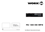
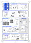
PA 50 CA TWO SERIES
PUBLIC ADRESS AMPLIFIER
9
8
MIC1
PHONO / AUX
MIC2
150kHz
0
1kHz
0
6kHz
0
10
11
12
13
7
14
6
15
5
16
4
17
3
MIN
MAX
MIN
MAX
-10
+10
-10
+10
-10
+10
2
18
1
19
0
FREQUENCY EQUALIZER
20
POWER
MASTER VOLUME
Equipson, S.A.
www.equipson.es
[email protected]
PA 50
User Manual / Instrucciones de Usuario
--1-!
!
!
PT
C12
.001U
AC
CN5 PT IN
R27
33K
4
3
R22
18K
C23
2200U/35V
C18
R28
47K
R29
47K
R30
12K
R31
12K
R33
15
R32
33K
D5
1/2W 9.1V
C1815
C27
33U/16V
C28
10U/16V
C31
100U/50V
Q7
Q4
C1815
C20
1U/50V
R25
5.6K
1W 47
R35
C24
2200U/35V
R36
10K
4001
C16
(MC).015U
470P
R24
330K
C17
100P
R23
390K
C30
47U/25V
R34
1W 2.2K
D4
C15
(MC).0033U
CN4
LED POW
C26
22U/16V
D1
4001
-
+
C14
47U/25V
R21
680
R19
100K
AC
B1
R20
270
470
C13
Q3
C1815
S1
R26
1K
C25
10U/16V
2
1
C11
10U/16V
3
2
1
AC 22OV
50HZ/50W
FUSE
POW-SW
C22
(MC).0047U
C21
(MC).0047U
R20
270
R17
2.2K
R16
2.2K
C10
.001U
R15
10K
CAUTION
R
L
5.6K
5.6K
Q5
C1815
D2
4148
R39
4.7K
Q8
C1815
C33
100U/50V
C29
33U/16V
C1815
Q6
C32
47U/25V
R38
8.2K
R37
12K
R40
1.2K
R41
100
R60
27K
R62
82K
OUT
Q19
C1815
D7
4001
C34
.47U/50V
M1
M2
GND
AUX
GND
OUT
6
~
2
N
C
!
R14
PHONO
R
R13
3
2
1
C39
100P
R59
47K
R42
22K
1
2
3
4
5
6
R87
1K
CN2
R43
2K
C37
22P
C35
100U/50V
R45
5.6K
Q9
C2240
R47
150
R81
7.5K
D12
4148
R44
39K
1
2
VR7
A50K
R53
100
R49
4.7K
CN7
D6
1W 18V
Q10
C2240
Q11
A1015
D8
4148
D9
4148
D10
4148
D11
4148
R83
7.5K
R82
22K
6
M1
5
M2
GND 4
AUX 3
GND 21
OUT
R67
1K
R50
100
Q12
C2240
R54
27K
C38
10U/16V
R48
4.7K
Q20
C1815
C57
10U/16V
R57
10
C36
100U/50V
R46
820
R52
15
Q13
A1015
R51
10
R86
7.5K
+VCC
R56
5W 0.2
Q15
D718
Q14
D718
R85
12K
CN8
PRIORITY
1
2
R55
5W 0.2
C58
100U/16V
-VCC
D13
1/2W 3V
R84
4.7K
The rear panel selector switch must be tuned in to "PHON" position when the amplifier is playing recorder.
VR3
A50K
VR2
A50K
R61
10K
R58
56K
"MIC", "AUX.CD", "PHON" positions are all set on volume controllers, which can freely adjust the volume needed by users.
3
2
1
VR1
A50K
+23V
R79
10K
R68
33P
C40
.47U/50V
C43
10U/16V
R63
680
R64
C42
6
5
OT
CN6
R86
1W 10
C59
(MC).068U
2
1
C41
33P
22K
33P
!
R80
10K
C44
1U/50V
7
OPT-30W
MC4558G
U1B
For greater operational flexibility, two Microphones can be inserted in the amplifier, on which also have "AUX" inputs, which
can provide for the use of radio tuner, CD player and other high
impedance, high power input .
100V
16 OHM
8 OHM
4 OHM
COM
C56
10U/16V
C52
330P
R75
75K
C50
(MC).0022U
R72
75K
C48
(MC).015U
R69
82K
R78
270K
R65
3.9K
R66
3.9K
R73
680
C49
33P
R71
820
C47
33P
R76
820
C51
10P
2
3
4
L
and risk occurring when you pull the power line out from AC
outlet.
8
AUX
{ You shall hold the plug firmly to avoid the pull-out of power line
VOL-PCB
You will find it safe and reliable to use the Series; AC
selector is made of insulating material and the rear panel is installed with connecting-ground terminal. Any other components
are all considered Safety-factor while assembling.
POW-PCB
C55
(MC).033U
R77
5.6K
Q18
C1815
C54
.22U/50V
R74
5.6K
Q17
C1815
C53
1U/50V
R70
5.6K
Q16
C1815
C45
150P
1
U1A
MC4558G
VR6
W50K
VR5
W50K
VR4
W50K
C46
.47U/50V
For the convenience of the users, the AC Mains of the amplifier
series is controlled by the power selector, it provide the two
kinds of voltages: 110V-120V / 220V-240V
CN9
PU-PCB
GENERAL DESCRIPTION:
1
2
COM
4W
8W
16W
100V
{ The plug of power line for this unit should be pulled out
from power outlet to cut down the power supply, when this
unit isn't used for a long period.
8W
8W
CAUTION
{ Don't touch the screw around the ventilation holes in the
Impedancia total 16W
bottom board. When heat sink working, the screw temperature
rises higher
Salida de 100 V (balanceada)
Cuando desea operar con altavoces a una distancia superior a
los 50 metros del amplificador, es recomendable la instalación
de transformadores de línea para prevenir las pérdidas de nivel.
Este método se conoce como distribución de tensión constante
y elimina el cálculo de impedancias de carga e instalaciones
serie-paralelo. Con este sistema todos los altavoces se
conectan en paralelo.
Esta salida de tensión constante distribuye la potencia entre los
altavoces. Cada uno de ellos debe disponer de un transformador
de línea de 100 V el cual marca la potencia deseada al
altavoz.
El número total de potencia soportada por los altavoces debe ser
la misma que la potencia de salida del amplificador o menor.
{ IF Connecting interference takes place in source circuit, THD
will be more than 10%
This broadcast system, main unit should be placed on
a solid
surface with a minimum distance of 1m from the back or side plate
to the wall and. rot in the following environments of cases:
{ Moist place;
{ Under direct radiation of sunlight or other strong heat radiation;
{ no air ventilation:
{ To prevent the risk of fire or electrical shock, never expose
this equipment to rain or dampness.
HANDLING THIS UNIT
COM
4W
8W
16W
Check if the power supply is being shut down, the power line is
pulled out from outlet and other lines connecting this unit are also
disconnected.
100V
DON'T DISASSEMBLE THIS UNIT
100V
Impedancia total 100V
--15--
100V
Don't disassemble and repair the unit by yourself, otherwise if may
induce electric shock or fires. If you can't remedy any occurred
trouble according to the methods described in the Last of this
manual, you must call a qualified technician or consult with our
company, A forced using if may cause electric shock or fires.
--2--
SPECIFICATIONS:
{ Microphone Sensitivity: -55dB
{ Aux.CD Sensitivity: -20dB
Salida de altavoces
2dB
El amplificador debe usarse junto con un sistema de altavoces de
4, 8, 16 ohms o 100 V de tensión constante.
2dB
{ OUTPUT POWER : 30W at 4W load
Salida de altavoces de baja impedancia : 4, 8, 16 ohm
(balanceado)
{ FREQUENCY RESPONSES : 100Hz-18KHz 3dB
{ DISTORTION : less than 1% (at 1KHz 1watts output)
{ Signal/Noise Ratio : More than-55dB
{ Hum or Noise level : 50mV
{ Tone Control Response :150HZ
10dB; 1K
10dB; 6K
{ Puncture Voltage at 5mA, 5Sec : 3750V
10dB
Lo terminales de baja impedancia 4, 8 16 ohms se usan para
un sistema con pocos altavoces o donde la distancia entre el
amplificador y los altavoces sea menor de 50 metros. Es
necesario que la impedancia total sea la marcada por la
conexión ( 4, 8 o 16 ohms) para una mejor eficacia.
Asegúrese que la impedancia total de los altavoces es la
misma, no incremente la potencia de salida del amplificador por
encima de lo permisible ya que los altavoces podrían dañarse.
{ Speaker outputs : 4, 8, 16ohms 100V
{ Dimensions : 320 (W) * 190 (D) * 80 (H) mm
{ Weight : 5Kgs
COM
4W
8W
16W
100V
NAME OF FUNCTIONS
1.
2.
3.
4.
5.
6.
7.
8.
9.
Power switch.
Master volume control.
6kHz Tone control.
1kHz Tone control.
150 Hz Tone control.
PHONO/AUX Volume control.
MIC2 Volume control.
MIC1 Volume control.
AC FUSE holder.
10.
11.
12.
13.
14.
15.
16.
17.
18.
AC CABLE.
PRIORITY control terminals.
Output terminals.
PHONO,AUX Selector switch.
MIC2 Input phone jack.
MIC1 Input phone jack.
PHONO jack (RCA).
AUX/CD jack (RCA).
Ground .
8W
Impedancia Total 4W
COM
4W
8W
16W
100V
16W
Impedancia Total 8W
--3--
8W
--14--
16W
Conexión de entrada
8
7
6
5
4
Micrófonos
MIC1
MIC2
PHONO / AUX
150kHz
0
1kHz
0
3
2
1
PA 50 CA TWO SERIES
PUBLIC ADRESS AMPLIFIER
9
10
La unidad dispone de 2 entradas de micrófono. Se usan para
micrófonos de baja impedancia (30 - 600 ohms). Un micro de
conexión desbalanceada con un cable de 10 a 20 metros deben
ser usado dependiendo de las características del micrófono.
11
12
8
6kHz
0
13
7
14
6
15
5
16
4
17
3
MIN
MAX
MIN
MAX
-10
+10
-10
+10
-10
+10
2
18
1
19
20
0
FREQUENCY EQUALIZER
POWER
MASTER VOLUME
9
18
17 16
15
MIC-1, MIC-2
Estas 2 entradas de micro desbalanceadas disponen de conector
de doble polo.
AC FUSE
Rheinland
Production inspected
Rheinland
Product Safety
MIC1
GND
CAUTION:
TO REDUCE THE RISK OF FIRE
REPLACE ONLY WITH SAME TYPE
AC FUSE.
geprufte
Sicherheit
AUX
PHONO
L
MIC2
OUTPUT
R
Micrófono desbalanceado de baja Z
AUX/CD
PHONO
PRIORITY
COM
4W
8W
16W 100V
Debe ser conectado a un cable simple apantallado
10
MIC
Micro desbalanceado
11
12
13
14
MUTE CONTROL (PRIORITY)
Conector unipolar
When the Terminals are short circuit, It will be shut down
MIC2 , AUX and phono, MIC1 is Priority output.
AUX/PHONE
Un sintonizador de radio, reproductor de CD, preamplificador
y otra fuente de alta nivel de señal de entrada, puede ser
conectado a la entrada AUX.
AUX
PRIORITY
COM
4W
8W
16W
100V
PHONO
SELECTOR
L
B
PHONO
AUX/CD
Seleccione AUX o PHONO. El selector está situado en el
panel trasero. Las dos tomas no pueden ser conectadas a
la vez.
1. Avoid using or storing it in a place where it is very dusty.
2. Also refrain from using it in direct sun or near a heater or
stove or in a similar place of high temperature.
Conexión de Salida
--13--
--4--
Input Connection
8
7
6
5
4
Microphones
MIC1
MIC2
PHONO / AUX
150kHz
0
1kHz
0
3
2
1
PA 50 CA TWO SERIES
PUBLIC ADRESS AMPLIFIER
9
10
Three microphone inputs are provided. They used with
unbalanced low impedance (30~600 ohms) microphoe. The
microphone with the unbalanced connection cable of 10-20m
may
be used depending on the microphone and its
characteristic.
11
12
8
6kHz
0
13
7
14
6
15
5
16
4
17
3
MIN
MAX
MIN
MAX
-10
+10
-10
+10
-10
+10
2
18
1
19
20
0
FREQUENCY EQUALIZER
POWER
MASTER VOLUME
9
18
17 16
15
MIC-1, MIC-2
AC FUSE
There TWO microphone inputs are unbalanced type and are
provided with a double pole phone jack.
Rheinland
Production inspected
Rheinland
Product Safety
MIC2
R
AUX/CD
PHONO
MIC
PHONO
L
PRIORITY
Unbalanced microphone
AUX
OUTPUT
Unbalanced Lo Z Microphone
May also be connected to the single conductor shielded
cable of unbalanced Lo Z microphone.
MIC1
GND
CAUTION:
TO REDUCE THE RISK OF FIRE
REPLACE ONLY WITH SAME TYPE
AC FUSE.
geprufte
Sicherheit
10
11
COM
4W
8W
16W 100V
12
13
14
CONTROL MUTE (PRIORIDAD)
Cuando se cortocircuitan los terminales, las entradas MIC2,
AUX, y PHONO se apagan y MIC1 tiene prioridad.
Single pole phone plug
AUX/PHONE
A radio tuner, tape player, chime , mixer preamplifer, compact
disk player or other high level input sources may be
connected to the AUX inputs.
AUX
PRIORITY
COM
4W
8W
16W
100V
PHONO
SELECTOR SWITCH
L
B
PHONO
AUX/CD
Should be selected either AUX or PHONO by using. The
AUX/PHONO Selector switch on the rear panel. AUX &
PHONO connot be used at the same time.
1. Evite usar o almacenar la unidad en un lugar polvoriento.
2. No lo utilice bajo la luz solar directa o cerca de estufas o
fuentes de calor similares.
Output Connection
--5--
--12--
ESPECIFICACIONES:
{ Sensibilidad del Micrófono: -55dB
{ Sensibilidad de Aux.CD: -20dB
Speaker Output
2dB
The amplifier may be used in conjunction with a speaker
rated at4, 8, 16 ohms or with 100-Volt constant-voltage
speaker systems.
2dB
{ POTENCIA DE SALIDA : 30W a 4W de carga
{ RESPUESTA DE FRECUENCIA : 100Hz-18KHz 3dB
{ DISTORSION : lMenos de 1% (a 1KHz 1W de salida)
{ Relación S/N : Mayor de -55dB
{ Nivel de zumbido o ruido : 50mV
{ Controles de tono :150HZ
10dB; 1K
10dB; 6K
{ Salidas de altavoz : 4, 8, 16 ohms 100V
{ Dimensiones : 320 (An) * 190 (Pr) * 80 (Al) mm
{ Peso : 5Kgs
10dB
Low impedance speaker output : 4, 8, 16 ohm
(balanced)
The low impedance 4, 8, 16 ohm terminal is provided for
connection of a few large-output speakers when constant
voltage speaker system is unnecessary or in case the
distance between the amplifier and the speakers is short
enough (less than 50m). It is requested that the total
speaker load impedance be correctly matched to the output
impedance (4, 8, 16 ohm) of the amplifier for most efficient
transfer of power.
Be sure that total impedance of speakers Amplifier must be
in equal, do not raise amplifier output power to above the
permissible input power of speaker if the latter is smaller
than the former. lf the amplifier output power should be
raised above it, by mistake, the speakers would be
damaged.
COM 4W
8W 16W 100V
CONTROLES Y FUNCIONES
1.
2.
3.
4.
5.
6.
7.
8.
9.
Interruptor de red.
Control de volumen Master.
Control de tono 6kHz .
Control de tono 1kHz
Control de tono 150 Hz
Volumen PHONO/AUX
Volumen MIC2
Volumen MIC1
Portafusible AC
10.
11.
12.
13.
14.
15.
16.
17.
18.
Cable AC
Terminales PRIORITY
Terminales de Salida
Selector PHONO,AUX
Entrada MIC2
Entrada MIC1
PHONO (RCA).
AUX/CD (RCA).
Tierra .
8W
Total impedance 4W
COM
4W
8W
16W
100V
16W
Total impedance 8W
--11--
8W
--6--
16W
COM
4W
8W
16W
100V
{ La clavija de red de la unidad debe ser desconectada de la
toma mural si el aparato no va a usarse durante un largo
periodo de tiempo.
8W
8W
PRECAUCION
{ No toque los tornillos junto a las salidas de ventilación
Impedancia total 16W
Cuando la etapa lleva un rato funcionando, la temperatura
en estos punto es muy elevada.
100 Volts speaker output (balanced)
When it is desired to operate the speakers from the
distance, over 50 meters of the amplifier, it is recommended that line matching transformers be installed on the
speaker units to prevent excessive line losses. This method
of load matching known as the constant voltage distribution
system eliminates the calculation of load impedancd and
series-parallel speaker arrangements. ln this method, all
speakers are connected inparallel.
These constant voltage outputs are most convenient for
distribution of power when a number of speakers are
installed . Each speaker must have 100-volt line transformer
with a tap that gives the power desired for that speaker .
The total number of powersettings for all speakers should
be equal to the amplifier power rating or less.
Este sistema de megafonía deber ser instalado sobre
una superficie sólida.
Con una distancia mínima de 1 metro entre el panel trasero y
la pared, evitando los siguientes ambientes:
{ Lugar húmedo;
{ Radiación solar directa u otra radiación de calor;
{ Lugar no ventilado:
{ Para prevenir el riesgo de fuego o descargas eléctricas, nunca
exponga este equipo a la lluvia o humedad.
COM
4W
8W
16W
MANEJANDO ESTA UNIDAD
Compruebe si la unidad está apagada, desconectada de la red
y el resto de líneas también están desconectadas.
100V
100V
Total impedance 100V
--7--
100V
NO DESMANTELE ESTA UNIDAD
No desmantele o repara la unidad Vd. Mismo, podría provocar
fuego o descargas eléctricas. Si no puede solucionar un problema
con los métodos descritos en el manual, contacte con un
técnico cualificado o consúltenos. Forzar su uso puede causar
descargas eléctricas o fuego.
--10--
--9-!
!
!
PT
C12
.001U
AC
CN5 PT IN
R27
33K
4
3
R22
18K
C23
2200U/35V
C18
R28
47K
R29
47K
R30
12K
R31
12K
R33
15
R32
33K
D5
1/2W 9.1V
C1815
C27
33U/16V
C28
10U/16V
C31
100U/50V
Q7
Q4
C1815
C20
1U/50V
R25
5.6K
1W 47
R35
C24
2200U/35V
R36
10K
4001
C16
(MC).015U
470P
R24
330K
C17
100P
R23
390K
C30
47U/25V
R34
1W 2.2K
D4
C15
(MC).0033U
CN4
LED POW
C26
22U/16V
D1
4001
-
+
C14
47U/25V
R21
680
R19
100K
AC
B1
R20
270
470
C13
Q3
C1815
S1
R26
1K
C25
10U/16V
2
1
C11
10U/16V
3
2
1
AC 22OV
50HZ/50W
FUSE
POW-SW
C22
(MC).0047U
C21
(MC).0047U
R20
270
R17
2.2K
R16
2.2K
C10
.001U
R15
10K
PRECAUCION
R
L
5.6K
5.6K
Q5
C1815
D2
4148
R39
4.7K
Q8
C1815
C33
100U/50V
C29
33U/16V
C1815
Q6
C32
47U/25V
R38
8.2K
R37
12K
R40
1.2K
R41
100
R60
27K
R62
82K
OUT
D7
4001
C34
.47U/50V
M1
M2
GND
AUX
GND
OUT
6
~
2
N
C
!
R14
PHONO
R
3
2
1
C39
100P
Q19
C1815
R42
22K
1
2
3
4
5
6
R87
1K
CN2
R43
2K
C37
22P
R45
5.6K
Q9
C2240
R47
150
R81
7.5K
D12
4148
C35
100U/50V
Vd. Encontrará un producto fiable y seguro. El selector Ac está
fabricado en material no conductor y el panel trasero dispone de
toma de terminal de toma de tierra.
VR3
A50K
VR2
A50K
R59
47K
R44
39K
1
2
VR7
A50K
R53
100
R49
4.7K
CN7
D6
1W 18V
Q10
C2240
Q11
A1015
D8
4148
D9
4148
D10
4148
D11
4148
R83
7.5K
R82
22K
6
M1
5
M2
GND 4
AUX 3
GND 21
OUT
R67
1K
R50
100
Q12
C2240
R54
27K
C38
10U/16V
R48
4.7K
Q20
C1815
C57
10U/16V
R57
10
C36
100U/50V
R46
820
R52
15
Q13
A1015
R51
10
R86
7.5K
+VCC
R56
5W 0.2
R55
5W 0.2
C58
100U/16V
-VCC
D13
1/2W 3V
R84
4.7K
Q15
D718
Q14
D718
R85
12K
CN8
PRIORITY
1
2
El selector situado en el panel trasero debe ser pasado a la
posición PHON cuando el amplificador esté en grabación.
R13
3
2
1
R61
10K
R58
56K
Las posiciones MIC, AUX.CD y PHON, tienen controles para
configurar el volumen a las necesidades del usuario.
VR1
A50K
VOL-PCB
+23V
R79
10K
R68
33P
C40
.47U/50V
C43
10U/16V
R63
680
R64
C42
6
5
OT
CN6
R86
1W 10
C59
(MC).068U
2
1
C41
33P
22K
33P
!
R80
10K
C44
1U/50V
7
OPT-30W
MC4558G
U1B
Para una mayor flexibilidad dispone de dos entradas de micrófono,
además de entradas AUX las cuales pueden usarse para dispositivos
tales como reproductores de CD, sintonizadores de radio, etc.
100V
16 OHM
8 OHM
4 OHM
COM
C56
10U/16V
C52
330P
R75
75K
C50
(MC).0022U
R72
75K
C48
(MC).015U
R69
82K
R78
270K
R65
3.9K
R66
3.9K
R73
680
C49
33P
R71
820
C47
33P
R76
820
C51
10P
2
3
4
L
desconexión de la toma mural.
8
AUX
{ Debe conectar firmemente la clavija de red para evitar su
POW-PCB
C55
(MC).033U
R77
5.6K
Q18
C1815
C54
.22U/50V
R74
5.6K
Q17
C1815
C53
1U/50V
R70
5.6K
Q16
C1815
C45
150P
1
U1A
MC4558G
Para la conveniencia del usuario, la alimentación AC del amplificador
está controlada por un selector que proporciona dos tipos de
voltaje: 110-120 V o 220-230 V.
CN9
PU-PCB
VR6
W50K
VR5
W50K
VR4
W50K
C46
.47U/50V
DESCRIPCION GENERAL
1
2