1
The PTC-0150 MiniCycler
Operations Manual
Version 4.0
MJ RESEARCH, Inc.
Waltham, MA
Copyright 1999, MJ Research, Inc. All rights reserved.
PTC-150 MiniCycler, Hot Bonnet, Chill-out, and Microseal are trademarks of MJ Research, Inc.
06108-05
Thermal cyclers can be used for a number of purposes, including the polymerase chain reaction
(PCR). PCR is covered by patents owned by Hoffmann-La Roche, Inc., and F. Hoffmann-La Roche,
Ltd., who have granted exclusive and nonexclusive licenses for some types of applications. Roche
and its licensees provide end-user licenses within their respective fields. These licenses have different terms depending on the particular application of PCR, and different rules may apply in
different countries. Anyone who intends to use MJ Research equipment to do PCR is encouraged
to contact Hoffmann-La Roche for more information, at one of the addresses below:
In the United States:
In other nations:
Kathe Kiehn
Licensing Manager
Roche Molecular Systems, Inc.
1145 Atlantic Avenue
Alameda, CA 94501 USA
(510) 814-2970
Fax: (510) 814-2977
Dr. Agnieszka Junosza-Jankowski
PCR Licensing Manager
F. Hoffmann-La Roche Ltd.
Building 222/350
CH-4002 Basel, Switzerland
41-61-687-3031
Fax: 41-61-687-2113
ii
Contents
Documentation Conventions ............................................................................................... iv
1. Introduction ................................................................................................................. 1-1
2. Layout and Specifications .......................................................................................... 2-1
3. Installation .................................................................................................................... 3-1
4. Operation ...................................................................................................................... 4-1
5. Running Protocols ....................................................................................................... 5-1
6. Creating Programs ...................................................................................................... 6-1
7. Editing Programs ........................................................................................................ 7-1
8. Networking .................................................................................................................. 8-1
9. Maintenance ................................................................................................................. 9-1
10. Troubleshooting ........................................................................................................... 10-1
Appendix A: Safety Warnings and Guidelines ............................................................. A-1
Appendix B: Warranties .................................................................................................... B-1
Appendix C: Shipping Instructions for US Residents .................................................. C-1
Appendix D: PCR Licensing Table .................................................................................. D-1
Appendix E: Declaration of CE Conformity .................................................................. E-1
Appendix F: Factory-installed Protocols ........................................................................ F-1
Index ..................................................................................................................................... In-1
iii
Documentation Conventions
Typographic Conventions
The names of keyboard keys are in sans serif type and placed within
double angle brackets:
Example:
«Proceed»
Items in programming menus are italicized:
Example:
Select Edit from the Main Menu.
Graphic Conventions
The programming screens displayed in the LCD window are represented
by a box containing two lines of text:
Example:
_RUN
Program
Enter
Program
Terminology
A programming option is termed “selected” when the cursor is positioned
in front of it. Use the «Select» keys (see fig. 2-3) to move the cursor. In
some screens selected items are also displayed in all-capital letters.
iv
1
Introduction
Meet the PTC-150 ........................................ 1-2
How to Use This Manual ............................. 1-2
Important Safety Information .................... 1-2
1-1
MiniCycler Operations Manual
Meet the PTC-150 MiniCycler
Thank you for purchasing an MJ RESEARCH PTC-150 MiniCycler. Designed
by a team of molecular biologists and engineers, the MiniCycler will meet
your needs for an easy-to-use, reliable, and compact programmable thermal cycler:
•
Easy-to-read programming interface for quick and painless programming
•
Choice of block or probe control
•
Space-saving design for easy setup and transportation
•
Instant Incubate feature for continuous-temperature incubations
•
Customizable factory-installed protocols
•
Hot Bonnet heated lid for oil-free cycling
How to Use This Manual
This manual contains all the information you need to operate your
MiniCycler safely and productively:
•
Chapter 2 describes the physical characteristics of the MiniCycler.
•
Chapters 3–5 describe the basics of installing and operating the
MiniCycler.
•
Chapters 6 and 7 describe programming the MiniCycler.
•
Chapter 8 explains the proper maintenance of the MiniCycler.
•
Chapter 9 offers troubleshooting information for the MiniCycler.
•
Chapter 10 describes how to change the MiniCycler’s block.
Important Safety Information
Safe operation of the MiniCycler begins with a complete understanding
of how the machine works. Please review this entire manual before attempting to operate the MiniCycler. Do not allow anyone who has not
reviewed this manual to operate the machine.
The MiniCycler can generate enough heat to inflict serious burns and
can deliver strong electrical shocks if not used according to the instructions in this manual. Please read the safety warnings and guidelines in
appendix B, and exercise all precautions outlined in them.
1-2
2
Layout and Specifications
Front View (Fig. 2-1) ................................... 2–2
Back View (Fig. 2-2) ................................... 2–2
Control Panel (Fig. 2-3) ............................... 2–3
Blocks Available ......................................... 2–4
Accessories ................................................ 2–4
Hot Bonnet (Fig. 2-4) ............................................... 2–4
Temperature Probe (Fig. 2-5) ................................... 2–5
Sponge Rubber Pads (Fig. 2-6) ................................ 2–5
Specifications .......................................................... 2–6
2-1
MiniCycler Operations Manual
Front View (Fig. 2-1)
1
4
7
8
0
2
5
Air intake vent
3
6
9
Power cord jack
Power switch
Back View (Fig. 2-2)
Lid latch
Data port
Air exhaust vent
2-2
Layout and Specifications
Control Panel (Fig. 2-3)
1
2
3
4
5
6
7
8
0
9
2-3
MiniCycler Operations Manual
Blocks Available
16-well block: holds 16 x 0.5mL tubes
25-well block: holds 25 x 0.2mL tubes or one 25-well V-bottom microplate
Accessories
Hot Bonnet (Fig. 2-4)
Available for 16- and 25-well blocks
Locking lever
Pin slot
2-4
Layout and Specifications
Temperature probe (Fig. 2-5)
Allows machine to control reactions according to a representative sample’s temperature. Available for 16- and 25-well blocks.
Magnetic sponge rubber pads (Fig. 2-6)
Used to help press tubes or a plate into the block. Available for use with 16- and 25-well blocks.
Thin (1cm) pad
(for 16–well block)
Thick (2cm) pad
(for 25–well block)
2-5
MiniCycler Operations Manual
Specifications
Thermal range:
–9° to 105°C (no more than 35°C below ambient temperature)
Accuracy:
±0.3°C of programmed target at 90°C, NIST traceable
Thermal homogeneity:
±0.4°C well–to–well within 12 seconds of arrival at 90°C
±0.3°C well–to–well within 40 seconds of arrival at 90°C
Sample capacity:
16-well block: 16 x 0.5mL tubes
25-well block: 25 x 0.2mL tubes or one 25-well microplate
2-6
Line voltage:
100–240VAC rms (no adjustment needed among voltages
within these ranges)
Frequency:
50–60Hz single phase
Power:
250W maximum
Fuses:
Two T2.5A/250V
Displays:
One 2 x 16 LCD alphanumeric display
Ports:
One 25-pin 8-bit parallel interface printer port (optional)
Memory:
80 typical programs, in nonvolatile memory; each program
may have up to 100 steps; maximum of 400 steps among all
programs
Weight:
3.0kg
Size:
22 x 28 x 11cm high
3
Installation
Packing List ................................................ 3-2
Setting Up the MiniCycler ........................... 3-2
Environmental Requirements ...................... 3-2
Power Supply Requirements ...................... 3-3
Air Supply Requirements ............................ 3-3
3-1
MiniCycler Operations Manual
Packing List
After unpacking the MiniCycler, check to see that you have received the
following:
•
One MiniCycler, with the sample block of your choice
•
One power cord
•
Two fuses
•
A 1cm–thick magnetic sponge-rubber pad (16-well block), or a 2cm–
thick pad (25-well block).
•
One red metal adapter plate (25–well block with heated lid only)
•
The PTC-150 MiniCycler Operations Manual (this document)
•
Warranty registration card and extended warranty application (US
customers only)
If any of these components are missing or damaged, contact MJ RESEARCH
or the authorized distributor from whom you purchased the MiniCycler
to obtain a replacement. Please save the original packing materials in
case you need to return the MiniCycler for service. See appendix D for
shipping instructions.
Setting Up the MiniCycler
Insert the power cord plug into its jack (see fig. 2-1), then plug the cord
into an electrical outlet (see “Power Supply Requirements,” below). Situate the machine according to the instructions below.
Environmental Requirements
Ensure that the area where the MiniCycler is installed meets the following conditions, for reasons of safety and performance:*
•
Indoor, nonexplosive environment
•
Ambient temperature 4–32°C
•
Relative humidity between 10% and 90%
•
Protection from excessive heat (e.g., radiators) and accidental spills
*Note: operation at altitudes significantly above sea-level may affect operation, particularly heat
dissipation.
3-2
Installation
Power Supply Requirements
The MiniCycler requires 100–240VAC, 50–60Hz, and a grounded outlet.
The machine can use current in the specified range without adjustment,
so there is no voltage-setting switch.
Air Supply Requirements
Air is taken in from a vent on the right side of the machine and exhausted
from a vent on the left side of the machine (see figs. 2-1 and 2-2). If the machine does not get enough air or gets air that is too warm, it can overheat.
Overheating can cause the machine to display a warning message, “H[eat]
S[ink] Overheating, Check Air Flow,” or even to shut itself off.
To prevent overheating, position the machine at least 10cm from other
thermal cyclers or walls. This is particularly important if two or more
MiniCyclers are used in one installation: one machine can blow all of its
exhaust air directly into the intake vent of its neighbor if they are placed
closely side by side. If the ambient air temperature exceeds 32°C, use
fans or adjust the air conditioning to cool the air that the machine receives. Keep the air intake vent clean and free of obstructions (e.g., loose
sheets of paper).
3-3
4
Operation
Turning the MiniCycler On .......................... 4–2
Using the Control Panel .............................. 4–2
Operation keys ........................................................ 4–2
Using the Probe ......................................... 4–9
Customizing the probe vessel ................................. 4–10
Adding the oil ......................................................... 4–10
Loading and connecting the probe ......................... 4–11
Running a protocol under probe control ................. 4–11
Opening and Closing the Lid ....................... 4–3
Mounting the Hot Bonnet ........................... 4–3
Selecting the Correct Sample Vessel ........... 4–4
0.5ml Tubes ............................................................. 4–4
0.2ml Tube ............................................................... 4–4
Microplates ............................................................. 4–4
Thin- vs. thick-walled tubes ....................................... 4–5
Positive–displacement pipette tips
and glass capillary tubes .................................. 4–6
Tube, Microplate, and Sealing System Selection
Chart ..................................................... 4–13
Safety Warning Regarding Use of 35S Nucle–
otides ..................................................... 4–14
Sealing Sample Vessels .............................. 4–6
Sealing with oil or wax ............................................ 4–6
Sealing with the Hot Bonnet and caps
or film sheets ............................................. 4–7
The Microseal Adapter ............................................ 4–7
Sealing glass capillary tubes ................................... 4–7
Sealing positive-displacement pipette tips ................ 4–7
Loading sample vessels .............................. 4–8
Loading tubes and plates ......................................... 4–8
Using the sponge rubber pad to improve
tube contact with the block ........................ 4–9
Using oil to improve thermal contact ....................... 4–9
4-1
MiniCycler Operations Manual
Turning the MiniCycler On
Move the power switch to “1” (the “On” position). A self-test of the heat
pump will usually begin running (see below). Its progress is tracked in a
screen in the LCD window:
SELF TEST
*
This screen disappears within 10 seconds. If a problem is detected, an
error message will be displayed.
Note: If either the heat sink or the block is not between 17°C and 30°C,
the machine will skip the self-test.
If the self-test does not detect any problems, the Run-Enter Menu is displayed:
_RUN
Program
Enter
Program
Using the Control Panel
The control panel (see fig. 2-3) includes operation keys, an LCD window
for displaying programming and machine status text, and a numeric keypad for entering values into programs.
Operation keys
4-2
•
Select keys (left and right arrows): Move the cursor one space or option to the left or right in the LCD window.
•
Proceed: Accepts a selected menu or screen option.
•
Cancel: Terminates a running protocol; during programming or editing, cancels the last entry.
•
Stop: Terminates a running protocol.
•
Pause: Pauses a running protocol.
•
Instant: Programs an Instant Incubation (see 5–6).
Operation
Opening and Closing the Lid
To open the MiniCycler, gently push the lid latch (see fig. 2–2) forward
until it disengages, then push the lid up. To close the lid, push the lid
down until the latch engages with a distinct click.
Mounting the Hot Bonnet
The Hot Bonnet mounts on two metal pins inside the retainer. When the
lid’s lever is lowered, the lid locks into place on the pins, and the inner
lid is lowered onto the tops of loaded sample vessels (fig. 4B). (Certain
models of the MiniCycler lack these pins. A retrofit to install them is available. Contact your distributor or MJ Research for further information.)
Follow this procedure to mount the Hot Bonnet:
1. Make sure the Hot Bonnet is the correct size for the block. The sticker
on the side of the unit identifies it by catalogue number: HBA–1151 is
for 16–well blocks; HBA–1152 is for 25–well blocks.
2. If only a few tubes are being run, make sure one tube is loaded into
each corner of the block, using empty tubes if necessary.
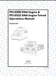
Figure 4-1 Mounting the Hot Bonnet. A, Rear view of MiniCycler showing correct cable orientation for
the Hot Bonnet. B, Hot Bonnet side view, showing mounting lever. C, Correctly mounted Hot Bonnet.
A
C
Hot Bonnet™
heated lid for the
PTC-150
MiniCyc ler
xxxxxxxxxxxxxxx xxxxxxxxxxxxxxx
xxxxxxxxxxx
Select
1
MiniCycler™
4
MJ RESEARCH
7
,
Pause
2
5
8
0
3
6
9
Proceed
Cancel
—
STOP
B
Mounting pin
4-3
MiniCycler Operations Manual
3. Plug the Hot Bonnet into its port at the back of the machine, so that
the cable is to the left of the connector as you face the back of the
machine (fig. 4-1A).
4. Raise the Hot Bonnet lever, and set the lid into the block with the
lever pointing to the right as you face the machine’s front.
5. Lower the lever as far as possible, which locks the Hot Bonnet into
place and lowers the heated lid onto the loaded tubes. Figure 4-1C
shows a correctly mounted Hot Bonnet.
Note: Intermittent beeping is an indication that the heated lid is not
being used correctly.
If a PTC 150 is beeping, it is likely there are not four tubes of the appropriate height in each of the four corners of the sample block. Placing a
tube in each of the four corners of the sample block will allow the lid to
seat squarely atop the block and the beeping will stop. The Minicycler
heated lid is unadjustable and designed to fit over standard sized flatcapped 0.5 mL tubes (on the 16 well cycler) or standard sized 0.2 mL
dome-capped tubes (on the 25 well cycler). If you would like to use a
non-standard tube height, or a flat-capped 0.2 mL tube, use the ADR–
0153 adapter plate provided.
If the unit is programmed and plugged in correctly, carefully try to determine if the heated lid is getting hot (do not touch the inside of the lid,
because if it is working, it will be extremely hot!). If the lid is cool, it may
be in need of repair. Please call customer service at (888) MJCYCLE.
Selecting the Correct Sample Vessel
MJ RESEARCH offers a full range of tubes and microplates, manufactured
to the specifications of each type of block to ensure a precise fit. See chapter appendix 4-A for a complete list. Keep in mind that differences in
tube and plate composition and wall thickness among the many brands
available can affect reaction results. Protocols may require some adjustment to ensure optimum results when using a new vessel type.
Note: certain tube and sealing options require the use of the Microseal
Adapter: see page 4–7.
0.5mL tubes
The 16-well block accepts either thick- or thin-walled tubes. Make sure
thick-walled 0.5mL tubes fit the wells snugly. Since these tubes were originally designed for centrifuges, some brands may not fit tightly in thermal cycler wells. Thin-walled 0.5mL tubes were specifically designed for
4-4
Operation
thermal cycling, and the higher quality brands provide a good and consistent fit. MJ RESEARCH provides thin- and thick-walled 0.5mL tubes designed for precise block fit.
0.2mL tubes
All types of thin-walled 0.2mL tubes may be used in the 25-well block.
MJ RESEARCH sells high-quality 0.2mL tubes in a number of styles, including individual tubes and strips.
Microplates
V-bottom polycarbonate or polypropylene microplates may be used in
the 25-well block as long as they fit the wells snugly. Polypropylene
microplates are usually preferred because they exhibit very low protein
binding and, unlike polycarbonate microplates, do not lose water vapor
through the vessel walls. This allows smaller sample volumes to be used—
as little as 5–10µL. Polypropylene microplates and compatible Microseal
‘A’ film, mats, or strip caps for sealing are available from MJ RESEARCH.
(See “Sealing with the Hot Bonnet and Caps or Film Sheets,” p. 4–7, for a
description of Microseal ‘A’.)
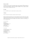
Ramp rate enhancement with thin-walled tubes. To compare ramp rates of sample temperature, 50µL samples of water were cycled in 0.5mL thin- and thick-walled tubes in a PTC-200
thermal cycler with a 60-well block. Thermal profile: 94°C, 120 sec; 62°C, 120 sec. Data
are shown for the third cycle. The cycler was run under Block Control, and the Hot Bonnet
was heated to 105°C and tightened to a half-turn past the touch point. The samples in thinwalled tubes reached the target temperature more quickly. In this example, over 30 seconds could be saved per cycle by using thin-walled tubes. A comparable ramp rate enhancement can be expected when using thin-walled tubes in the PTC-150 MiniCycler.
{
17-sec
difference
Block
Thin wall
Thick wall
{
Figure 4-2
15-sec difference
4-5
MiniCycler Operations Manual
Thin- vs. thick-walled tubes
The thickness of sample tubes directly affects the speed of sample heating and thus the amount of time required for incubations (see fig. 4–2).
Thick-walled tubes delay sample heating since heat transfers more slowly
through the tubes’ walls. For the earliest types of thermal cyclers this
delay mattered little. These machines’ ramp rates were so slow (below
1°C/sec) that there was plenty of time for heat to transfer through the
tube wall to the sample during a given incubation.
Modern thermal cyclers have much faster ramp rates, so the faster heat
transfer provided by thin-walled tubes allows protocols to be significantly
shortened. For example, in the reaction illustrated in figure 4-2, over 30
seconds can be saved per cycle by using thin-walled tubes, for an overall
savings of 15 minutes in a 30-cycle run.
Sealing Sample Vessels
Water can evaporate from reaction mixtures during thermal cycling,
changing the concentration of reagents. A layer of oil or wax will completely prevent evaporation from tubes and microplates, but Microseal
film, mats, or caps, in conjunction with the Hot Bonnet Heated lid, are
also effective and far less messy and inconvenient.
Sealing with oil or wax
Mineral oil, silicone oil, paraffin wax, or Chill-out™ liquid wax may be
used to seal tubes or plate wells. Use only a small amount of oil or wax;
1–3 drops (15-50µL) are usually sufficient. Use the same amount of oil or
wax in all sample vessels to ensure a uniform thermal profile.
Some paraffin waxes solidify at room temperature. The wax can then be
pierced with a micropipette and the samples drawn off. Silicone oil and
mineral oil can be poured off or aspirated from tubes if the samples are
first frozen (–15° to –20°C). The samples are usually pure enough for analysis without an extraction.
Chill-out™ liquid wax (available from MJ RESEARCH) is an easy-to-use
alternative to oil. This purified paraffinic oil solidifies at 14°C and is liquid at room temperature. By programming a hold step at low temperature, the wax can be solidified at the end of a run. A pipette can then be
used to pierce the wax in the tubes and remove the samples. The wax is
dyed red to assist in monitoring its use (clear Chill–out wax is also available). The dye has no adverse effects on fluorescent gel analysis of reaction products.
4-6
Operation
Sealing with the Hot Bonnet and caps or film sheets
The inner lid of the Hot Bonnet heats to 108°C during a 99-second preheat. When heated, the lid maintains a higher temperature in the upper
part of the reaction vessels, which prevents condensation, refluxing, and
changes in reaction concentrations. The lid also exerts pressure on the
tops of vessels loaded into the sample block, helping to maintain a vapor-tight seal and to firmly seat the vessels in the block.
Caps, film, or mats must be used along with the Hot Bonnet to prevent
evaporative losses. Tight-fitting caps are recommended for minimal vapor loss (and for long-term storage of reaction products). For optimal
sealing, use the Easy Cap Tool (ECT–1000) to firmly seat the caps in the
tubes. Microseal ‘A’ film may be used when a pristine sealing surface is
required for each run. When a reusable sealer is appropriate, the 96-well
Microseal ‘M’ rubber sealing mats are easy to use and effective. Microseal
‘A’ and ‘M’ sealers are sized for an array of 96 0.2mL tubes and must be
cut to fit the 25-well block. Follow the manufacturer’s instructions when
applying caps, films, and mats.
Note: After a hold at below-ambient temperatures, a ring of condensation may form in tubes above the liquid level but below the top of the
sample block. This is not a cause for concern since it occurs only at the
final cool-down step, when thermal cycling is finished.
The Microseal Adapter
Certain tube and sealing options require the use of the Microseal Adapter
(ADR–0153). This device is to be used in conjunction with flat–cap tubes,
an array of capless 2mL tubes, or a 25–well Multiplate sealed with
Microseal A. The adapter is essentially a heat–conducting metal spacer:
it raises the clearance of lower–profile sample tubes that would otherwise not engage the MiniCycler lid’s safety interlock, and it provides the
lid-pressure the Microseal film requires for proper sealing.
Loading Sample Vessels
Loading tubes and plates
If you will be using the Hot Bonnet with a small number of tubes, load at
least one empty tube in each corner of the block (see “Mounting the Hot
Bonnet,” p. 4–3).
To ensure uniform heating and cooling of samples, tubes and plates must
make good thermal contact with the block. Adequate contact is ensured
4-7
MiniCycler Operations Manual
by always following these recommendations:
•
Check that the block is clean before loading samples (see chapter 8
for instructions on cleaning block wells).
•
Firmly press the tubes or microplate into the wells, and use the heated
lid or the sponge rubber pad to ensure that tubes are firmly pressed
into the block. (Do not use the sponge rubber pad with heated block.)
Using the sponge rubber pad to improve tube contact with the block
When using the MiniCycler without the Hot Bonnet, a magnetic sponge–
rubber pad may be attached to the lid to help press loaded tubes into the
block wells. Two sizes of pad are available:
•
A 1cm pad for use with 0.5mL tubes in the 16-well block
•
A 2cm pad for use with 0.2mL tubes or 25-well microplates
Attach the magnetic backing of the pad to the metal plate under the lid.
When the lid is closed, the pad will firmly seat tubes or microplates.
Using the Probe
An in-sample temperature probe is available for MiniCyclers with the
16- or 25-well block. The probe consists of a precision thermistor mounted
in a thin-walled plastic tube (see fig. 2-5). A thin wire, encased in a small
plastic tube, runs from the thermistor to the probe’s plug, which is inserted into a jack at the side of the block. A specific amount of oil is added
to the probe tube (see “Adding the oil,” below), to serve as the representative sample. The tube is loaded into the block, where it can serve as the
control reference for any programmed target temperature between 0 and
100°C.
When a probe-control protocol is run, the MiniCycler controls the block’s
temperature to keep the probe at the programmed temperature, using
feedback information from the thermistor. Protocols must be tailored to
fit this control mechanism (see chapter 6).
Customizing the probe vessel
For the most precise control of sample temperatures, install the probe’s
wire and thermistor in the same type of tube that the samples will be
placed in.
Follow these steps to customize the probe vessel:
1. Cut the hinge to the probe tube’s lid. Gently remove the thermistor
from the probe tube; the lid will come off with it.
4-8
Operation
2. Remove the lid from the new probe tube. Add the amount of oil
speficied under “Adding the Oil.”
3. Gently place the thermistor into the new tube, and snap the lid closed.
Make sure that the lid from the original probe tube (attached to the
thermistor) fits on the new tube and that the tube is long enough to
accommodate the probe wire. The sensor should rest on the tube’s
bottom.
Caution:
The thermistor is extremely fragile. Handle it with great
care.
Adding the oil
Viscous oils (not water!) are the best choice for the probe tube’s representative sample. They closely mimic the thermal characteristics of buffer
solution, which changes temperature sluggishly due to the high specific
heat of water.
Light and heavy mineral oil and silicone oil may be used (table 4-1). MJ
RESEARCH recommends using heavy mineral oil because the formula for
determining the correct volume of oil to use is easy to remember, and it is
widely available and inexpensive. But whichever type of oil you use, be
careful to add the correct amount of oil.
Loading and connecting the probe
Seat the probe tube in the center of the block.
Plug the probe into its jack (see fig. 4-3). One of the pin holes in the probe
jack has been blocked off so that the probe cannot be plugged in incorrectly.
Running a protocol under probe control
To run a protocol under probe control, load and connect the probe as
described above. Select a protocol that has been designed for probe control and press «Proceed». The following screen will be displayed:
In-sample Probe
Control? _NO Yes
Select Yes and press «Proceed». The protocol will begin running under
probe control.
4-9
MiniCycler Operations Manual
Figure 4-3 Correctly installed probe.
Table 4-1 Calculating the correct amount of oil
Type of oil
Sigma number
Amount to use
Heavy mineral oil
400-5
1 x volume of buffer in individual sample tube
+ 1 x volume of oil overlay
Light mineral oil
M5904
1.4 x volume of buffer in individual sample tube
+ 1 x volume of oil overlay
Silicone oil
DMPS-5X
1.7 x volume of buffer in individual sample tube
+ 1 x volume of oil overlay
Silicone oil
DMPS-V
2.7 x volume of buffer in individual sample tube
+ 1 x volume of oil overlay
4-10
Operation
Tube, Microplate, and Sealing
System Selection Chart
Key
●
❍
Reaction vessel or sealer fits block without modification.
Reaction vessel or sealer must be cut to fit.
MJ R ESEARCH Reaction Vessels
Thermal
Cycler
Blocks
Sealing Options for Oil-Free
Cycling
Description
MJ RESEARCH
Catalog #
●
0.5ml tubes w/caps, thin wall
TBI-0501
●
0.5ml tubes w/caps, thick wall TBI-0601
16
(0.5ml)
25
(0.2ml)
Microseal
'A' film
MSA-5001
Microseal
'M' mat
MSM-1001
8-Strip
caps
TCS-0801
12-Strip
caps
TCS-1201
●
0.2ml tubes w/flat caps
TFI-0201
●
0.2ml tubes w/domed caps
TWI-0201
●
0.2ml tubes, no caps
TBI-0201
❍
❍
❍
❍
❍
8-strip 0.2-ml tubes
TBS-0201
❍
❍
❍
❍
❍
12-strip 0.2-ml tubes
TBS-1201
❍
❍
❍
❍
●
Multiplate 25-well microplates MLP-2501
❍
❍
❍
❍
❍
Multiplate 24-well microplates MLP-2401
❍
❍
❍
❍
❍
Multiplate 48-well microplates MLP-4801
❍
❍
❍
❍
❍
Multiplate 96-well microplates MLP-9601
❍
❍
❍
❍
Note: All tubes and Multiplate microplates are made from polypropylene plastic. Microseal ‘A’
sealing film and Microseal ‘M’ mats are supplied in a 96–well format and must be cut to fit the
Minicycler.
4-11
MiniCycler Operations Manual
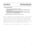
Safety Warning Regarding Use of 35S
Nucleotides
Some researchers have experienced a problem with radioactive contamination when using 35S in
thermal cyclers. This problem has occurred with all types of reaction vessels.
The Problem
When 35S nucleotides are thermally cycled, a volatile chemical breakdown product forms, probably SO2. This product can escape the vessel and contaminate the sample block of a thermal cycler,
and possibly the air in the laboratory. Contamination has been reported with microassay plates,
0.2-mL tubes, and 0.5-mL tubes.
Polycarbonate microplates
These microplates present the largest risk of contamination. Polycarbonate is somewhat permeable both to water and the 35S breakdown product. This problem is exacerbated when polycarbonate plates are held at high temperatures for long periods of time, or when the plates are sealed for
oil-free thermal cycling.
0.2mL Polypropylene tubes and 25-well polypropylene microplates
These tubes are manufactured with very thin walls to enhance thermal transfer. The thin walls are
somewhat fragile and can develop small cracks when subject to mechanical stress. Undamaged
thin polypropylene tubes may also be somewhat permeable to the 35S breakdown product. Either
way, there have been reports of 35S passing through the walls of microplates and 0.2-mL tubes of
several different brands during thermal cycling.
0.5-mL Polypropylene tubes
Contamination problems are rarer with this type of tube, but instances have been reported.
The Solution
1. Substitute the low-energy beta emitter 33P in cycle sequencing. 33P nucleotides are not subject
to the same kind of chemical breakdown as 35S nucleotides, and they have not been associated
with volatile breakdown products.
2. If 35S must be used, three things will help control contamination: an oil overlay inside the
tubes, mineral oil in the thermal cycler outside the tubes, and use of thick-walled 0.5-ml tubes.
Always run 35S thermal cycling reactions in a fume hood, and be aware that vessels may be
contaminated on the outside after thermal cycling. Please be certain that you are using the
4-12
Operation
appropriate detection methods and cleaning procedures for this isotope. Consult your radiation
safety officer for his or her recommendations.
If mild cleaning agents do not remove radioactivity, harsher cleaners may be used. Users have
suggested the detergent PCC-54 (Pierce Chemical Co., Rockford, Illinois; Pierce Eurochemie B.V.,
Holland), Micro Cleaning Solution (Cole-Parmer, Niles, Illinois), and Dow Bathroom Cleaner (available in supermarkets).
Caution:
Harsh cleaning agents are corrosive to aluminum and must never be used on bare
aluminum blocks. MJ RESEARCH blocks are anodized, so they have a protective coating
of aluminum oxide. Still, harsh agents (such as those above) must be thoroughly rinsed
away within a few minutes of application, or the anodization will degrade.
4-13
5
Running Protocols
Running a Protocol ..................................... 5-2
Running a protocol with the Hot Bonnet installed .... 5-2
Running a protocol under probe control .................. 5-3
Reading the Runtime Screen ....................... 5-3
Reading the Protocol Completion Screen .... 5-4
Manually Stepping Through a Protocol ...... 5-4
Pausing a Running Protocol ........................ 5-5
Stopping a Running Protocol ...................... 5-5
Resuming a Protocol after a Power
Outage ............................................ 5-5
Running an Instant Incubation .................... 5-6
5-1
MiniCycler Operations Manual
Running a Protocol
Either a custom-designed protocol or one of the factory-installed protocols may be run. See appendix F for descriptions of the factory-installed
protocols, which may be edited to fit your needs.
To run a protocol, select Run Program from the Run-Enter Menu, then
press «Proceed».
If protocols have been stored in the machine, they will be displayed.
Press one of the «Select» keys until the name of the protocol you wish to
run is displayed. Press «Proceed» again. The protocol will begin running.
Run
QUIKSTEP
?
Running a protocol with the Hot Bonnet installed
Select a protocol to run as described above and press «Proceed». The
following screen will be displayed:
Use Heated Lid?
_YES No
Select Yes and press «Proceed». The Hot Bonnet will begin its 99-second
preheat to 108°C. A screen showing a timer that counts down the seconds
of this preheat period will be displayed:
QUIKSTEP
Preheat time: 89
When the lid has fully preheated, the protocol will begin to run.
If the Hot Bonnet is removed when it is preheating, if tubes are not present
in all corners of the block, or if the Hot Bonnet cable is disconnected from
the machine, the MiniCycler will begin beeping, and the following message will be displayed:
Check Bonnet
Placement...
5-2
Running Protocols
When the Hot Bonnet is replaced in the well, or tubes are placed in all
corners of the block, or the cable is connected to the machine, the Hot
Bonnet will stop beeping and re-start its 99-second preheat.
Note: If the Hot Bonnet is removed when a programmed protocol is
running, the MiniCycler will begin beeping but no message will be displayed.
Running a protocol under probe control
To run a protocol under probe control, load and connect the probe (see p.
4–12). Select a protocol that has been designed for probe control. Do not
use probe control to run a protocol designed for block control. Press «Proceed». The following screen will be displayed:
In-sample Probe
Control? –NO Yes
Select Yes and press «Proceed». The protocol will begin running under
probe control.
If probe control is not desired, select No and press «Proceed». The protocol will begin running under block control.
Reading the Runtime Screen
During a protocol run, a runtime screen will be displayed:
QUIKSTEP 1
1
65.4
This screen lists the program name (Quikstep in the example above), the
protocol step that is running (1), the block temperature (65.4°C), and the
cycle number (1). If the probe is installed, the temperature of the representative sample inside the probe is displayed (62.7°C):
CUSTOM 1
1
65.4
62.7
5-3
MiniCycler Operations Manual
The runtime screen will show each step of the protocol as it executes.
When the target temperature for a given step is reached, a timer in the
middle of the second line will begin running:
QUIKSTEP 2 92.0
1
00:10
The timer shows the length of time the samples have been held at the
displayed temperature. When another step begins, the timer disappears
until the new step’s target temperature is reached. At this point the timer
begins running for the new step.
Reading the Protocol C ompletion Screen
When the protocol ends, a message is displayed:
QUIKSTEP
Complete
5 75.0
The number of the last step in the protocol (5 in the example above) and
the temperature of the block at the completion of the program (75°) are
displayed in the upper right-hand corner of the screen. The temperature
reading will change as the block cools to ambient temperature.
Press «Proceed» to remove this screen. The Run-Enter Menu will be displayed, and another protocol may be run.
Manually Stepping Through a Protocol
A running protocol can be manually advanced through its steps. As soon
as a step has reached its target temperature (i.e., when the timer begins
running for the step), press «Proceed» to progress the protocol to its next
programmed step. The next step will immediately be displayed.
5-4
Running Protocols
Note: Pressing «Proceed» while a step is ramping will have no effect.
A step must have reached its target temperature before the protocol can
be manually advanced to the next step.
Protocols can be programmed to require manual stepping (see p. 6.10).
Pausing a Running Protocol
Press «Pause» to temporarily stop a running protocol. If «Pause» is
pressed during temperature ramping, the protocol will pause as soon as
the target temperature is reached, and samples will be held at the displayed temperature. If «Pause» is pressed after a step has reached its
target temperature, the protocol will immediately begin holding samples
at the current incubation temperature. The timer will stop running, and
the word “Pause” will be displayed:
QUIKSTEP 2 92.0
9
PAUSE
To resume the protocol, press «Pause» again. The timer will begin running again, and the protocol will complete the step that was paused and
continue on to the next step.
Stopping a Running Protocol
Press «Stop» or «Cancel» to stop a running protocol. The program will
stop running, and the Run-Enter Menu will be displayed again.
Note: Turning off the machine will not stop a running protocol. Instead,
the MiniCycler will assume that a power outage has occurred and will
resume running the protocol when the machine is turned on again (see
below).
5-5
MiniCycler Operations Manual
Resuming a Protocol after a Power Outage
If a power failure occurs when a protocol is running, the MiniCycler will
hold the protocol in memory for at least 24 hours and sometimes up to 10
days. (The exact duration depends on environmental conditions.)
When power is restored, the protocol will begin running again at the
point at which it was stopped. When the protocol ends, the protocol
completion screen will be displayed, with a special notice on its last line:
QUIKSTEPCOMPLETE
Press Proceed
Press «Proceed» as instructed. A screen about the power outage will be
displayed. The screen will identify the step and the cycle that were running when the power failure occurred:
AC POWER FAILED
Cyc 3
Step 2
Press «Proceed» to remove this screen. The Run-Enter Menu will be displayed again.
Running an Instant Incubation
The MiniCycler may be used as a constant-temperature incubator by
pressing «Instant» (the zero key) while the Run-Enter Menu is displayed.
A screen allowing entry of the incubation temperature will be displayed:
TEMP:_
Type any incubation temperature from –9.0 to 105.0˚C, then press «Proceed». The MiniCycler will incubate the sample at the specified temperature.
When the sample block reaches the incubation temperature, a timer will
begin running in the lower right-hand corner of the screen. To stop and
start the timer, press «Pause». To stop an instant incubation, press «Cancel» or «Stop» (see “Stopping a Running Protocol”).
5-6
6
Programming
Designing a New Program ......................... 6-2
Translating a Protocol into a program ..................... 6-2
Using the GoTo Step to write short programs .......... 6-2
Choosing a temperature control method ................. 6-3
Block control ..................................................... 6-3
Probe control .................................................... 6-3
Entering a new program .......................................... 6-4
Initiating the program .............................................. 6-4
Naming the program ............................................... 6-5
Entering the program steps ...................................... 6-5
Entering a temperature step ............................. 6-5
Entering a GoTo step ........................................ 6-6
Entering an increment step ............................... 6-7
Entering an extend step .................................... 6-8
Entering a slope step ........................................ 6-9
Entering the End step ........................................ 6-10
Programming an indefinite Hold .............................. 6-10
Deleting an Incomplete Program ................ 6-12
Deleting a Program fromemory ................. 6-12
Listing a Program ....................................... 6-12
Printing a Program ..................................... 6-13
Creating a program that requires manual
stepping ........................................... 6-10
Editing While Entering a Program ............... 6-10
Changing the last value entered or last menu
option chosen ........................................... 6-10
Changing all the values in the step being
entered ...................................................... 6-11
Changing values in earlier steps of a program
being entered ............................................ 6-11
6-1
MiniCycler Operations Manual
MiniCycler programs consist of a series of steps encoding a protocol. These
steps are run using one of two temperature control methods: block control or probe control.
Programs may contain six types of steps. Two of the step types are mandatory, and four are optional:
1. Temperature step (mandatory): Sets a temperature for the block and the
length of time it is held at that temperature. The MiniCycler brings the
block to this temperature at its maximum rate of heating or cooling (up
to 2.4°C/sec) unless modifying instructions are added to the program.
2. GoTo step (optional): Causes the program to cycle back to an earlier
step for a specified number of times (up to 9,999 times).
3. Increment step (optional): Allows a progressive increase or decrease
of temperature (–6.0° to 6.0°C/cycle) each time a step is executed in a
GoTo cycle (useful in “touchdown” programs).
4. Extend step (optional): Allows a progressive lengthening or shortening of a temperature step hold (by 1–60 sec/cycle) each time a step is
executed in a cycle (useful for accommodating an enzyme with diminishing activity).
5. Slope step (optional): Allow a slower-than-maximum rate of heating or cooling.
6. End step (mandatory): Instructs the MiniCycler to shut down its heat
pump because the last line of the program has run.
Designing a New Program
Using the GoTo step to write short programs
The GoTo step allows programs of many repetitious steps to be shortened to just a few lines. When the program encounters a GoTo step, it
returns to the specified step, repeats that step, and repeats all steps that
follow, back to the GoTo step. When the program has returned, or cycled,
back to the step the specified number of times, the program moves on to
the step that follows the GoTo step.
For example, consider a basic cycle sequencing protocol consisting of 30
repeats of the denaturation and annealing/extension steps. Rather than
listing all 60 steps, use a GoTo step to design a short, easy-to-enter program:
6-2
Programming
Raw program:
Shortened program:
1.
2.
3.
4.
5.
6.
7.
1. 92˚ for 30 sec
2. 60˚ for 3 min
3. GoTo step 1, 29 times (i.e., cycle
back to step 1 and repeat steps
1, and 2, 29 more times )
4. End
92˚ for 30 sec
60˚ for 3 min
92˚ for 30 sec
60˚ for 3 min
92˚ for 30 sec
60˚ for 3 min
92˚ for 30 sec
[continues for total of 60 lines]
Choosing a temperature control method
The MiniCycler can control block temperature in two ways, each of which
has different implications for the speed and accuracy of sample heating:
•
Block control: The MiniCycler adjusts the block’s temperature to
maintain the block at programmed temperatures, independent of
sample temperature.
•
Probe control: The MiniCycler adjusts the block’s temperature to
maintain an in–sample probe at programmed temperatures.
Block control
Under block control, the temperature of samples always lags behind the
temperature of the block. The duration of this time lag depends on type
of sample vessel and sample volume, but typically is between 10 and 30
seconds.
Probe control
Probe control is available for MiniCyclers equipped with the 16- or 25well block. Special care must be taken to fill the probe with the correct
amount of oil and to seat the probe and the samples correctly. Otherwise,
actual sample temperatures can vary widely from the probe’s temperature. Probe control cannot be used with microplates or slides.
Under probe control, the machine will slightly overshoot its heat targets
to account for the time required for heat to transfer to the sensor within
the probe tube. Therefore, probe control protocols typically require incubations that are 15–20 seconds shorter than incubations for block control
protocols. For example, a denaturation step in a block-control protocol
calling for 92°C for 30 sec would be reduced to 92°C for 10 sec in a probecontrol protocol.
6-3
MiniCycler Operations Manual
Entering a New Program
Programming the MiniCycler occurs in three stages:
1. Initiating the program
2. Naming the program
3. Entering the program’s steps, including the End step
Each stage involves typing values from the keyboard or making selections from a menu. Programs may be edited as they are being entered or
after they have been stored. Programs are automatically saved when the
End step is entered.
Initiating the program
To initiate a new program, select Enter Program from the Run-Enter Menu,
then press «Proceed». The Main Menu will be displayed:
_NEW
Edit
List
Delete
Select New, then press «Proceed». The naming screen will be displayed:
Name
A
Naming the program
Program names may be up to eight characters long and may consist of
any combination of letters (Roman and Greek), numbers, punctuation
marks, or Japanese Katakana.
Press the right «Select» key to scroll forward and the left «Select»
key to scroll backward through the alphabets and characters available, which are presented in this order: Roman alphabet, selected
Greek letters, punctuation marks, numbers. To access the Japanese
Katakana syllabary, press the «.» key. A second press of «.» returns the
machine to Western characters.
When the character needed is displayed next to Name, press «Proceed».
6-4
Programming
The character will be accepted, and the cursor will move one space to the
right. Numbers and dashes may also be inserted by pressing the corresponding keys on the keypad.
When the name is complete, press «Proceed» once to accept the last character and again to accept the whole name. If the name is already in use
for a program, a screen saying “Name In Use” will be displayed. If this
happens, press «Proceed», then enter a different name.
Entering the program steps
When the name has been entered (CUSTOM1 is used in the following
examples), the Enter Menu will be displayed:
Step 1
_TEMP
Goto Option End
Use this menu to enter each step of the program:
•
Temp enters a temperature step.
•
GoTo enters a GoTo step.
•
Option enters an increment, extend, or slope step.
•
End enters the End step.
Entering a temperature step
To enter a temperature step, select Temp from the Enter Menu, then press
«Proceed». The first Temp screen will be displayed:
Step 1
Temperature _
The first line of this screen shows the number of the step being programmed (1 is used in the example above). The second line of the screen
allows a target temperature (in degrees Celsius) to be entered for the step.
Type any number between –9.0 and 105.0 as the target temperature (92.5
is used in the example below):
Step 1
Temperature 92.5
6-5
MiniCycler Operations Manual
Press «Proceed». The temperature will be accepted, and a screen allowing entry of an incubation time will be displayed:
Step 1
Min
Hrs _
Sec
A value must be entered for Hrs (hours), Min (minutes), and Sec (seconds). Use the «Select» keys to move the cursor to each option, and do
one of the following: type a number, or press «Proceed» to automatically
enter a value of 0.
For example, to enter an incubation time of 30 seconds, press «Proceed»
twice. The value of 0 will automatically be entered for Hrs and Min , and
the cursor will be positioned at Sec. Use the keyboard to type “30.” The
screen will look like this:
Step 1
Min 0
Hrs 0
Sec 30_
Press «Proceed». The times will be accepted, and the Enter Menu will be
displayed again. Use the Enter Menu to add another step to the program.
Entering a GoTo step
To enter a GoTo step, select GoTo from the Enter Menu and press «Proceed». The first GoTo screen will be displayed:
Step 2
Go to step _
The first line of this screen shows the number of the step being programmed (2 is used in the example above). The second line of the screen
allows entry of the number of the step the program should cycle back to.
Type the number of the step the program should cycle back to (1 is used
in the example below):
Step 2
Go to step 1
Press «Proceed». The number will be accepted, and a screen allowing
6-6
Programming
entry of an additional number of cycles will be displayed:
Step 2 Go to 1
_
more times
Type the additional number of times the program should cycle back to
the step (24 is used in the example below):
Step 2 Go to 1
24
more times
Press «Proceed». The number will be accepted, and the Enter Menu will be
displayed again. Use the Enter Menu to add another step to the program.
Entering an increment step
To enter an increment step, select Option from the Enter Menu and press
«Proceed». The Options Menu will be displayed:
Step 3
_EXTEND
Increment Slope
Select Increment and press «Proceed». A screen allowing entry of the initial incubation temperature for the step will be displayed:
Step 3
Temperature _
Type a temperature and press «Proceed». The number will be accepted,
and a screen allowing entry of an incubation time will be displayed:
Step 3
Min _
Sec
Type a number for Min and Sec. Press «Proceed» to automatically enter a
value of 0.
6-7
MiniCycler Operations Manual
When the numbers have been typed, press «Proceed». The numbers will
be accepted, and a screen allowing entry of a temperature increment or
decrement will be displayed:
Step 3
Add _
° /cycle
Type a temperature from –6.0 to 6.0°C (the maximum programmable
range) as the number of degrees by which the incubation temperature
will increase or decrease each time the step is executed in a cycle. Use a
negative number to program a progressive decrease of temperature, and
a positive number to program a progressive increase.
When the number has been typed, press «Proceed». The number will be
accepted, and the Enter Menu will be displayed again. Use the Enter Menu
to add another step to the program.
Entering an extend step
To enter an extend step, select Option from the Enter Menu and press
«Proceed». The Options Menu (see above) will be displayed. Select Extend and press «Proceed». Type the initial incubation temperature and
incubation time as for an increment step (see above), and press «Proceed». The temperature and time will be accepted, and a screen allowing
entry of a time increment or decrement will be displayed:
Step 4
Extend _
S/cyc
Type a number from –60 to 60 (the maximum programmable range) as
the number of seconds by which the incubation time will increase or decrease each time the step is executed in a cycle. Use a negative number to
program a progressive decrease of incubation time, and a positive number to program a progressive increase.
When the number has been typed, press «Proceed». The number will be
accepted, and the Enter Menu will be displayed again. Use the Enter Menu
to add another step to the program.
Entering a slope step
To enter a slope step, two values must be specified:
•
6-8
The desired temperature change for the step: This is the difference
between the temperature of the block at the beginning of the slope
step and the desired block temperature at the end of the slope step.
For example, if the final temperature of the preceding step is 92°C
Programming
and the desired final temperature of the slope step is 65°C, the desired temperature change is 27°C.
•
The slope rate for the step: This is a ratio of degrees per unit of time
(usually degrees per second). Use the smallest convenient time increment to achieve the smoothest temperature curve for the step. For
example, 0.1°C per second will give a smoother curve than 1°C per
10 seconds.
To enter a slope step, select Option from the Enter Menu and press «Proceed». The Options Menu (see above) will be displayed. Select Slope and
press «Proceed». A screen allowing entry of the magnitude of the temperature change for the step will be displayed:
Step 4
Slope _
°
Type a number for the desired temperature change and press «Proceed».
The number will be accepted, and a screen allowing entry of the rate of
heating or cooling will be displayed:
_ ° per
Hrs
Min
Sec
Type a number from 0.1 to 1.5 (the maximum programmable temperature range) for the numerator of the slope rate, and press «Proceed». The
temperature will be accepted, and the cursor will move to Hrs. Type a
time value for the denominator of the slope rate. A number must be entered for Hrs, Min, and Sec. Press «Proceed» to move the cursor to the
next time element.
When the denominator has been typed, press «Proceed». The numbers
will be accepted into the program, and the Enter Menu will be displayed
again. Use the Enter Menu to add another step to the program.
Entering the End Step
To enter the End step, select End from the Enter Menu, then press «Proceed». A confirmation screen will be displayed:
Step 6
End
Press «Proceed». The End step will be entered into the program. The
program will be stored, and the Run-Enter Menu will be displayed.
6-9
MiniCycler Operations Manual
Programming an Indefinite Hold
Programs can be designed to end in an indefinite hold at a specified temperature. This allows completed reaction products to be held at a stable
refrigeration temperature at the end of a run, until they can be conveniently removed.
To program an indefinite hold, program a temperature step immediately
before the protocol’s End step. Type the desired temperature for the indefinite hold, then give the step an incubation time of 0 hours, 0 minutes,
and 0 seconds. When this temperature step is reached, the block will heat
or cool the samples to the desired temperature and hold them there until
you press «Proceed», or manually end the program by pressing «Cancel» or «Stop».
Creating a Program That Requires Manual Stepping
To create a program that must be manually progressed to each step, program an indefinite hold for each temperature step in the protocol (see
“Programming an Indefinite Hold,” above). When the protocol runs, you
may then advance it through its steps at the time desired by pressing
«Proceed».
Editing While Entering a Program
Changing the last value entered or last menu option
chosen
To change the last value entered or last menu option chosen, press «Cancel». The choice just made will be cancelled, and another value may be
entered or another menu option chosen. Press «Proceed» after changing
a value, so that the program will accept it.
Changing all the values in the step being entered
To change all the values in the step currently being entered, repeatedly
press «Cancel». Each time you press the key, the cursor will move backward through the values for the step, deleting them as it moves. When all
values for the step have been deleted, enter new values, or press «Cancel» one more time to display the Enter Menu for the step. At this point
you can re-enter the step.
6-10
Programming
Changing values in earlier steps of a program being
entered
To change one or more values in earlier steps of the program you are
entering, repeatedly press «Cancel» until the Enter Menu for the step
you are working on is displayed. Press «Cancel» one more time to
display the last-entered step. The step will be displayed in a special
format:
CUSTOM1 3 94.0
00:00:10
In the example above, the last-entered step is a temperature step. The
step number is 3, and the temperature for the step is 94.0°C. The incubation time is displayed in the form of 00:00:00. The first two digits represent hours, the second two digits represent minutes, and the last two
digits represent seconds. The step in the example is programmed for a
10-second incubation.
At this point you may press the arrow keys to scroll through the
program’s steps. To change temperature, time, and cycling values see
chapter 7.
Note: You cannot change the program name, step number, or step type.
To change the program’s name or the order or type of its steps, delete the
program (see below) and then re-enter it.
After you have made all necessary changes, press the right «Select» key
until the Enter menu is displayed for the next step in the program. Continue entering the new program.
Deleting an Incomplete Program
To delete a program that you are in the process of entering, enter the End
step and press «Proceed», which will store the program. Then delete the
program from memory (see below).
6-11
MiniCycler Operations Manual
Deleting a Program from Memory
Any program in memory may be deleted. To delete a program, select
Enter Program from the Run-Enter Menu and press «Proceed». The Main
Menu will be displayed. Select Delete and press «Proceed». The deletion
screen will be displayed for the first program in memory:
Delete
CUSTOM1?
Press the «Select» keys until the name of the program to be deleted is
displayed. When the correct name is displayed, press «Proceed». The
program will be deleted, and the Run-Enter Menu will be displayed.
Listing a Program
Use the List option on the Main Menu to display all of a program’s steps
in the LCD window. To enter List mode, select Enter Program from the
Run-Enter Menu and press «Proceed». The Main Menu will be displayed.
Select List and press «Proceed».
Press the «Select» keys until the name of the program to be listed is displayed, then press «Proceed». The first step in the program will be displayed in the LCD window. Press the right «Select» key to scroll forward
and the left «Select» key to scroll backward through the list of steps.
To exit List mode, scroll to the last step of the program, then press the
right «Select» key once. The Run-Enter Menu will be displayed.
Note: No program values can be changed in List mode. To change program values, see chapter 7 .
6-12
Programming
Printing a Program
If your MiniCycler has the optional 8-bit, 25-pin parallel printer port, it
can print all the programs stored in the machine
To do this, follow the instructions under “Listing a Program” to enter
List mode. If a printer is connected to the printer port, the list program
screen will give you the option to print as well as list programs in the
LCD window. Select Print Programs and press «Proceed». Each program
stored in the machine will be printed.
The MiniCycler parallel printer port is compatible with Epson® LX-810
dot matrix printers and many other IBM compatibles. Only printers that
support the Epson® extended graphics set will be able to print the degree character (°). Other printers will print an x instead of the degree
character.
6-13
7
Editing Programs
Initiating Editing ......................................... 7-2
Editing the Program ................................... 7-2
Editing temperatures and cycling values .................. 7-2
Editing a time value ................................................. 7-3
Editing a slope step ................................................. 7-4
7-1
MiniCycler Operations Manual
Initiating Editing
To edit an existing program the machine must be in Edit mode. To enter
Edit mode, select Enter Program from the Run-Enter Menu and press «Proceed». The Main Menu will be displayed. Select Edit from the Main Menu
and press «Proceed». A screen similar to the following will be displayed:
Edit
CUSTOM1?
The machine is now in Edit mode. Use the «Select» keys to select the
program you wish to edit. When the name of the desired program is displayed, press «Proceed». The first step in the program will be displayed:
CUSTOM1 1 94.0
00:00:20
The programmed temperature for this step is 94.0°C. The incubation time is
displayed in the form of 00:00:00. The first two digits represent hours, the
second two digits represent minutes, and the last two digits represent seconds. The step in the example is programmed for a 20-second incubation.
Editing the Program
Press the left «Select» key to scroll backward through the program steps,
and the right «Select» key to scroll forward. As the left or right «Select»
key is pressed, the cursor will progressively move backward or forward
through each value in a step, and then back to the preceding or forward
to the following step.
Editing temperatures and cycling values
To change a temperature or a cycling value, position the cursor on it and
type the new value. Press «Proceed». The new value will be accepted,
and the cursor will move forward to the next value in the step.
To cancel a change, press «Cancel». The just-typed value will disappear,
and a blank line will be displayed in its place. Type a new value and
press «Proceed».
7-2
Editing Programs
Note: Be careful when editing program values. Once a value is changed
or deleted, you cannot make it reappear.
Editing a time value
To edit any part of a time value, you must retype the number for each
element in the time value: hours, minutes, and seconds. Press «Proceed»
after typing each time element. The number just typed will be accepted,
and the cursor will move to the next time element. To enter a value of 00
for hours, type a zero, then press «Proceed». The second zero will automatically be entered. To enter a value of 00 for minutes or seconds, simply press «Proceed». Both zeros will be entered at once.
For example, to change the time value for the example above from 00:00:10
to 00:00:30, press the right arrow key to move the cursor to the first digit
of the time value:
CUSTOM1 1 94.0
00:00:30
Type a zero. The zero will become the first digit of the hours element, and
the values for minutes and seconds will disappear from the screen:
CUSTOM1 1
0 : :
94.0
Press «Proceed». A second zero will automatically be entered for the hours
element, and the cursor will move to the minutes element:
CUSTOM1 1
00:_ :
94.0
Press «Proceed». Two zeros will automatically be entered for the minutes element, and the cursor will move to the seconds element:
CUSTOM1 1
00:00:_
94.0
Type the number 30, then press «Proceed». The number will be entered
7-3
MiniCycler Operations Manual
for the seconds element, and the cursor will move back to the first digit
for the hours:
CUSTOM1 1 94.0
00:00:30
Editing a slope step
To edit a slope step you must retype both a sign (plus or minus) and a
number. Press «.» (the period key) to enter a plus sign and «-» (the hyphen) to enter a negative sign. Press «Proceed» after entering the new
slope step value.
7-4
8
Maintenance
Cleaning the Chassis and Block ................... 8-2
Cleaning the Air Vents ................................ 8-2
Cleaning Radioactive or Biohazardous
Materials Out of the Block .................... 8-2
Changing the Fuses .................................... 8-3
8-1
MiniCycler Operations Manual
Cleaning the Chassis and Block
Clean the outside of the MiniCycler with a damp, soft cloth whenever
something has been spilled on it or the chassis is dusty. A mild soap solution may be used if needed.
Clean the block’s wells whenever anything is spilled into them or when
the oil in them is discolored or contains particulate matter. It is particularly important to prevent the buildup of old, dirty oil, which will interfere with vessel seating and diminish thermal coupling of sample vessels
to the block.
Clean the wells with a swab moistened with water, 95% ethanol, or, if a
thorough cleaning is needed, a 1:100 dilution in water of 5.25% (0.7M) sodium hypochlorite (household bleach). If using sodium hypochlorite, swab
the wells with water afterward to remove all traces of it. Do not clean the
block with caustic or strongly alkaline solutions (e.g., strong soaps, ammonia, sodium hypochlorite at a higher concentration than specified above).
These can damage the block’s protective anodized coating.
Cleaning the Air Vents
Clean the air intake and exhaust vents with a soft-bristle brush, a damp
cloth, or a vacuum cleaner whenever dust is visible in them. If these vents
become clogged with dust and debris, airflow to the MiniCycler’s heat
sink is hampered, eventually causing overheating and shutdowns (see
“Air Supply Requirements,” chapter 3).
Cleaning Radioactive or Biohazardous Materials Out of
the Block
When cleaning machines that have been running radioactive or
biohazardous reactions, consult your institution’s radiation safety officer
or biosafety officer regarding methods, monitoring, and disposing of contaminated materials.
If mild cleaning agents do not remove radioactivity, harsher chemicals
may be used. Users have suggested the detergent PCC-54 (Pierce Chemical Co., Rockford, Illinois; Pierce Eurochemie B.V., Holland), Micro Cleaning Solution (Cole-Parmer, Niles, Illinois), and Dow Bathroom Cleaner
(available in supermarkets).
8-2
Maintenance
Caution:
Harsh cleaning agents are corrosive to aluminum and
must never be used on bare aluminum blocks. MJ
REASEARCH blocks are anodized, so they have a protective
coating of aluminum oxide. Still, harsh agents (such as
those above) must be thoroughly rinsed away within a few
minutes of application, or the anodization will degrade.
Changing the Fuses
The circuits in the MiniCycler are protected by two fuses (2.5TA 250V
Slo-blo). When a fuse blows, the MiniCycler immediately shuts down
and cannot be turned back on. The machine records the event as a power
loss, so if a protocol is running when a fuse blows, the machine will resume the protocol run when the fuse is replaced and power restored (see
“Resuming a Protocol after a Power Outage,” chapter 5).
Warning:
The MiniCycler incorporates neutral fusing, which means
that live power may still be available inside the unit even
when a fuse has blown or been removed. Unplug the
MiniCycler from the electrical outlet before opening its case.
Never connect a power cord to the machine when the case
is open.
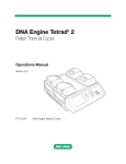
Figure 8-1 Changine a fuse.
A.
B.
8-3
MiniCycler Operations Manual
Follow this procedure to change the fuse:
1. Move the power switch to the “0” (off) position. Disconnect the power
cord from the side of the machine.
2. Insert one corner of a small flat-head screwdriver into the slot at the
left side of the fuse block (fig. 8-1A). Gently pry the block loose, and
pull it down and out. The fuses will be visible (fig. 8-1B).
3. Remove the fuses and examine them. A flat-head screwdriver may be
used to pry the fuses loose, if necessary. A broken central wire or darkened glass indicates that a fuse has blown and should be replaced.
4. Gently press the fuse block back in place, and reconnect the power cord.
8-4
9
Troubleshooting
Error Messages ........................................... 9-2
Problems Related to Protocols ..................... 9-3
Problems Related to Machine
Performance ................................... 9-5
9-1
MiniCycler Operations Manual
Error Messages
Error Message
Cause
Action
Check ADC
Analog/digital converter not
giving proper output.
Contact MJ RESEARCH or your
distributor.
Check Block Sensor
Block's temperature sensor or
sensor circuitry is
malfunctioning.
Block may need servicing. Contact
MJ RESEARCH or your distributor.
Check EEPROM
User Memory failing to store
data.
Turn machine off, then on again. If
error message appears again,
contact MJ Research or your
distributor.
Heat Pump Not
Functioning
Heat pump is not working, so
machine has shut down.
Cycler needs servicing. Contact MJ
RESEARCH or your local distributor.
HS Overheating,
Check Air Flow
Machine is not getting enough
air, or air being taken in is not
cool enough.
Ensure machine is at least 10cm
away from walls and other
equipment. Make sure air being
taken in is cool (see chap. 3). If
message persists, cycler may need
servicing; contact MJ RESEARCH or
your distributor.
9-2
Troubleshooting
Problems Related to Protocols
Problem
Cause
Action
Reaction is working
but broad low molecular weight band is
seen in gels.
Primer-dimer material often
produces a broad band in the
<100bp region of gels.
If obtaining appropriate reaction product/s, no need to
change anything.
Minimize primer-dimer
production by designing
primers with no 3' selfcomplementarity.
Reoptimize magnesium concentration and annealing temperature to maximize desired product and minimize primerdimers.
Reaction working but
unexpected extra
products or smear is
seen.
Nonspecific hybridization occurring during setup.
Program a hot start into the
protocol.
Reaction component concentration Check concentrations of compotoo high or too low.
nents. May need to reoptimize
magnesium concentration.
Annealing temperature too low.
Reoptimize annealing
temperature. It should be
within a few degrees of the
temperature for the primers
using the nearest-neighbor
method.
Template not of sufficient purity.
Check extraction and purification protocols. Add additional
purification steps if necessary.
Multiple templates or host DNA
in sequencing reactions.
Check nucleic acid preparations
by gel electrophoresis.
(Continued)
9-3
MiniCycler Operations Manual
Problem
Cause
Action
No reaction products
obtained.
Protocol contains a wrong value.
Use List to check protocol's
temperature control method,
temperatures, and times.
Reaction component omitted from Check reaction assembly protomixture.
col, ensuring that mixture contains appropriate components
in correct concentrations.
Denaturation temperature too
low.
Use 92° C for denaturation.
Annealing temperature too high
for primers.
Check for appropriate annealing temperatures of primers,
using available computer programs or empirical testing.
Probe failed, causing machine to
run protocol under block control.
Check screen for probe failure
error message. Probe may need
servicing or replacing. Call MJ
RESEARCH or your local distributor.
Probe not filled with correct
amount of oil.
Fill probe tube with correct
amount of oil (see p. 4-11).
Reaction mix contains an inhibitor "Spike" a complete reaction mix
(e.g., heme from blood).
with a control template and
primer set.
Reaction vessels not making good
thermal contact with sample
block.
9-4
Use only high-quality
tubes/plates that fit block
snugly. Ensure that wells are
free of foreign materials that
would interfere with tube/plate
seating.
Troubleshooting
Problems Related to Machine Performance
Problem
Cause
Action
Beeper sounds continuously (MiniCyclers with
Hot Bonnet only).
Hot Bonnet is not plugged into
the machine.
Cancel protocol. Plug Hot Bonnet cable into its port at back of
machine, and restart protocol.
Tubes are not in all 4 corners
of the block so lid is tilted.
Put tubes (empty if necessary) in
all 4 corners of the block.
A microplate or flat-capped
tubes are being used.
Need to use red metal adapter.
Block does not heat or
cool.
Heat pump or fans are
malfunctioning.
Contact MJ RESEARCH or your
distributor.
Machine will not power
up.
Power cable is not plugged
into machine, electrical outlet
is dead, or fuse has blown
Make sure power cord is
plugged into machine correctly.
Make sure electrical outlet is
operational. Check fuses.
Machine starts in middle Machine was turned off before
of a protocol when
protocol run had finished.
turned on.
See p. 5-5.
Strange characters
appear in LCD window,
or text in window
freezes or scrolls repetitively.
Reset the microprocessor by
turning machine off, then back
on while pressing the «Cancel»
key at the same time. If problem
persists, contact MJ RESEARCH or
your distributor.
LCD window or machine
microprocessor is malfunctioning.
9-5
10
Changing the Sample Block
Opening and Closing the MiniCycler’s
Case ..................................................... 10-2
Changing the Sample Block ........................ 10-2
10-1
MiniCycler Operations Manual
Caution:
Avoid changing the sample block frequently. The cables
and connectors are fragile and can be damaged in as few
as 50–100 uses.
Opening and Closing the MiniCycler’s Case
Follow this procedure to open and close the MiniCycler’s case:
1.
Unplug the power cord from the machine. Put the power switch in
the “0” position.
2. Using a Philips-head screwdriver, remove the large black screw on
the left side of the machine (fig. 10-1A).
3. Place the tip of a finger under the edge of the case, just beneath the
screw hole, and pull outward and upward on the case. The case latch
will release, and the case can then be lifted up and over to reveal the
interior of the machine.
Warning: Do not plug the power cord into the machine while
the case is open. You could receive a serious shock.
Caution:
The case is designed to open to a 90° angle. Do not
force the case to open wider than this, to avoid damaging the case’s hinge.
4. To close the case, push it down to cover the machine. Replace the
screw holding the case to the machine base.
Figure 10-1 Opening the MiniCycler case.
10-2
Changing the Sample Block
Changing the Sample Block
Follow this procedure to change the sample block:
1. Unplug the power cord from the machine and open the case as described above.
2. Locate the block, and identify the two white ribbon cables exiting
from it (fig. 10-2).
3. Grasp the ribbon cables just above their board connections and gently pull upward to disconnect them.
4. Locate the metal latch holding the block onto the circuit board (fig.
10-3). Press down on the latch, then pull the block toward the latch.
The block will slide out over the latch (fig. 10-4).
✓
Tip:
If you have trouble sliding the block out, insert the tip of a
flat-head screwdriver between the latch and the bottom
of the instrument. Use the screwdriver to push the latch
down while sliding out the block.
5. Slide the new block into place; firm pressure may be required.
6. Reconnect the ribbon cables to their pins on the board. Make sure to
align the pins with to the connectors correctly.
7. Close the case as described above.
Figure 10-2 Changing the sample block.
10-3
MiniCycler Operations Manual
Figure 10-3 Releasing the sample block latch.
Figure 10-4 Sliding the sample block out.
10-4
Appendix A
Appendix A
Safety Warnings
Warning: Operating the MiniCycler before reading this manual can constitute a personal
injury hazard. Only qualified laboratory personnel trained in the safe use of electrical equipment should operate this machine.
Warning: Always disconnect the power cord before opening the base of the PTC-150 MiniCycler, to avoid receiving an electrical shock.
Warning: The MiniCycler incorporates neutral fusing, which means that live power may still be
available inside the unit even if a fuse has blown or been removed. Although the
machine will not be operational, you could still receive a shock if you fail to disconnect the power cord from the machine before opening the base, after a fuse has
blown. Never open the MiniCycler’s base with the power cord connected, and
never connect the power cord to the machine when the base is open, even if a fuse
has blown.
Warning: The MiniCycler Hot Bonnet inner lid can become hot enough to inflict serious
burns during the course of normal operation. Use extreme caution if the Hot Bonnet is removed while still hot. Do not touch the inner lid when it is hot. Do not
place a hot MiniCycler Hot Bonnet on a flammable surface, to avoid starting a fire.
Warning: The MiniCycler’s block can become hot enough during the course of normal operation to cause burns or cause liquids to boil explosively. Wear safety goggles or
other eye protection at all times during operation.
Safe Use Guidelines
The MiniCycler is designed to be safe to operate under the following conditions:*
•
Indoor use
•
Ambient temperature 4–32˚C
•
Relative humidity 10–90%, noncondensing
•
Transient overvoltage per Installation Category II, IEC 664
•
Pollution degree 2, in accordance with IEC 664
*Note: operation at altitudes significantly above sea-level may affect operation, particularly heat dissipation.
A-1
MiniCycler Operations Manual
Electromagnetic Interference
The MiniCycler has been tested and found to comply with the limits for a Class A digital device,
pursuant to part 15 of the US FCC Rules. These limits are designed to provide a reasonable protection against harmful interference when the equipment is operated in a commercial environment.
This machine generates, uses, and can radiate radiofrequency energy and, if not installed and
used in accordance with the instruction manual, may cause harmful interference to radio communications. Operation of this machine in a residential area is likely to cause harmful interference, in
which case the user will be required to correct the interference at his or her own expense.
In addition, the MiniCycler design has been tested and found to comply with the EMC standards
for emissions and susceptibility established by the European Union at time of manufacture.
FCC Warning
Changes or modifications to the MiniCycler not expressly approved by the party responsible for
compliance could void the user’s authority to operate the equipment.
A-2
Appendix B
Appendix B
Warranties
U.S. Domestic Warranty, Standard
MJ RESEARCH, Inc. warrants NEW MJ RESEARCH BRAND THERMAL CYCLERS (MODELS PTC100, PTC-150, PTC-200 & PTC-225) against defects in material and workmanship for a period of
two years from the date of purchase. If a defect is discovered, MJ RESEARCH, Inc. will, at its option,
repair, replace, or refund the purchase price of the THERMAL CYCLER at no charge to the customer, provided the product is returned to MJ RESEARCH, Inc. within the warranty period. In no
event will MJ RESEARCH, Inc. be responsible for damage resulting from accident, abuse, misuses, or
inadequate packaging of returned goods.
ANY implied warranties, including implied warranties of the merchantability and fitness for a
particular purpose, are limited in duration to TWO years from the date of original retail purchase
of this product.
The warranty and remedies set forth above are exclusive and in lieu of all others, oral or written,
expressed or implied. No MJ RESEARCH dealer, agent, or employee is authorized to make any modification, addition, or extension to this warranty, except in the form of the extended warranty outlined below.
MJ RESEARCH, Inc. is not responsible for special, incidental, or consequential damages resulting
from any breach of warranty, or under any other legal theory, including downtime, lost samples or
experiments, lost reagents, lost profits, goodwill, damage to or replacement of equipment, property, and any costs of recovering or reproducing experimental results and data.
Exclusions: This warranty applies only to machines sold in the U.S.A. Under no circumstance will MJ
RESEARCH ship a repaired or replaced machine, or grant a refund of purchase price, to a user in a nation
in which there was an authorized MJ RESEARCH distributor at the time of purchase. THIS WARRANTY
IS NOT TRANSFERABLE FROM THE ORIGINAL PURCHASER TO A SUBSEQUENT OWNER. FURTHERMORE, THIS WARRANTY DOES NOT APPLY TO INSTRUMENTS USED OUTSIDE THE
U.S.A., EXCEPT WHEN EXPRESSLY AUTHORIZED IN WRITING BY MJ RESEARCH, INC.
U.S. Domestic Extended Warranty, Optional
MJ RESEARCH, Inc. will offer to each ORIGINAL PURCHASER of an MJ RESEARCH BRAND thermal
cycler the opportunity to purchase an extension of the warranty coverage explained above for an
additional two years. The coverage must be purchased through a purchase order received by MJ
RESEARCH, Inc. within 30 days of receipt of the offer of extended warranty or the offer to renew the
extended warranty. These offers apply only to machines sold and used in the U.S.A.
B-1
MiniCycler Operations Manual
Some states OF THE U.S.A. do not allow the exclusion or limitation of incidental or consequential
damages or limitations on how long an implied warranty lasts, so the above limitation or exclusion may not apply to you. This warranty gives you specific legal rights. You may also have other
rights depending upon your state of residence.
All provisions of this warranty are voided if the product is resold, repaired, or modified by anyone other than MJ RESEARCH or an authorized distributor.
B-2
Appendix C
Appendix C
Shipping Instructions for US
Residents
Users residing in the United States should follow these instructions for shipping a machine to MJ
RESEARCH for factory repair or an upgrade. Users outside of the United States should send machines to their distributor, in accordance with shipping instructions obtained from the distributor.
1. Call MJ RESEARCH to obtain a return materials authorization (RMA) number. Machines returned
without an RMA number will be refused by the Receiving Department.
2. Thoroughly clean the machine, removing oil and radioactive and other biohazardous substances. To protect the health of our employees, MJ RESEARCH will not repair or upgrade any
machine that is excessively oily or that emits ionizing radiation upon arrival at our factory.
PLEASE ELIMINATE ALL BIOHAZARDS!
3. Pack the machine in its original packaging. If this has been misplaced or discarded, call MJ
RESEARCH to request shipment of packaging materials. You can also request a loaner machine,
which will be provided if available (a rental fee may apply). You can use the loaner’s packaging to return the machine needing repair.
4. Write the RMA number on the outside of the box.
5. Ship the machine (freight prepaid) to the following address. We recommend you purchase
insurance from your shipper.
Ship to:
Repair Department
MJ Research, Inc.
590 Lincoln St.
Waltham, MA 02451
C-1
Appendix D
Appendix D
PCR Licensing table
PCR* LICENSING INFORMATION
Background: The PCR process is covered by patents owned by Hoffmann-La Roche, Inc. and F. Hoffmann-La Roche Ltd. (collectively called Roche). Roche has
granted exclusive and non-exclusive licenses for various applications of PCR, and Roche and its licensees provide end-user licenses within their designated fields.
These licenses have different terms depending on the field, and different rules may apply in different countries. In the U.S. and most other nations, the user should
always have proper license to perform PCR.
The following table reflects MJ Research’s understanding of the requirements set by Roche and its licensees for particular classes of users to purchase PCR licenses
in the United States. This table is not endorsed by Roche, and all thermal cycler users are encouraged to contact Roche for further information.
“Authorization” of thermal cyclers: The Perkin-Elmer Corporation holds the exclusive license from Roche to grant sublicenses to perform PCR in specific fields,
such as research and forensics. Since 1992, Perkin Elmer has generally issued licenses in the form of a running royalty with sale of specific licensed enzymes, which
carry a label stating that reactions must be run in an “authorized” thermal cycler.
MJ Research does not sell “authorized” thermal cyclers and believes that PE’s right to charge a thermal cycler “authorization” fee is probably legally unenforceable
in the U.S. (this matter is under review by the U.S. Federal District Court). However, Perkin Elmer will sell such an “authorization” for any individual thermal cycler.
It may be prudent in some circumstances to “authorize” an MJ cycler after purchase.
PCR* for Human & Animal Diagnostics†
TYPE OF USE
WITH DIAGNOSTIC
SERVICE LICENSES‡
WITH LICENSED
TEST KITS‡
THERMAL CYCLER Usually None (see Usually None (see
actual terms of
actual terms of license)
LICENSE*
ENZYME LICENSE*
Usually None (see
actual terms of
Usually None (see
actual terms of
OTHER PCR†
NON-PCR†
RESEARCH,
FORENSICS, ETC.
CYCLE SEQUENCING,
PRINS, ETC.*
Thermal Cycler
“authorized” for PCR
None
Enzyme with PCR
label license
None
N. B. For each column, both the indicated thermal cycler license and the indicated enzyme license are
* This table refers to PCR licenses only; other processes, and particular types of enzyme or thermal cycler, may require separate
license.
Addresses for Contacting HoffmannLaRoche:
In the United States:
Kathe Kiehn
Licensing Manager
Roche Molecular Systems, Inc.
1145 Atlantic Avenue
Alameda CA 94501 USA
(510) 814-2970 • Fax: (510) 814-2977
In other nations:
Dr. Agnieszka Junosza-Jankowski
PCR Licensing Manager
F. Hoffmann-La Roche Ltd.
Building 222/350
CH-4002 Basel, Switzerland
41 61 687 3031 • Fax: 41 61 687 2113
† For definitive information on where your application fits, please contact Roche.
Note: Please do not construe the information on this page as legal advice—for more information, please contact your institution’s legal department.
D-1
Appendix E
Appendix E
CE Conformity
DECLARATION OF CONFORMITY
MJ RESEARCH, INC. hereby declares that the MJ RESEARCH PTC-150
MiniCycler™ thermal cycler conforms to the following directives and standards:
APPLICATION OF COUNCIL DIRECTIVES: 89/336/EEC & 73/23/EEC
STANDARDS TO WHICH CONFORMITY IS DECLARED: EN55011; EN50082-1; Canadian Standards Association (CSA) Std. 1010 (EMC for industrial, scientific, medical equipment; EMC for generic immunity;
compliance to low-voltage directive respectively)
TYPE OF EQUIPMENT: Scientific Equipment (for Laboratories)
MODEL NUMBER: PTC-150
YEARS OF MANUFACTURE: 1997 and onward
MJ RESEARCH INC, as manufacturer of the equipment described above, certifies that this model has
been tested and conforms to the applicable Directives and Standards of the European Union (EU) as
described above. Test data to verify this conformity are available for inspection at the MJ RESEARCH, INC.
at the address listed below. The instrument in question carries the “CE” mark on the nameplate.
MANUFACTURER’S OFFICIAL:
Robert A Iovanni
Senior Electrical Engineer
MJ RESEARCH, INC.
590 Lincoln Street
Waltham, Massachusetts 02451
UNITED STATES OF AMERICA
Tel: (617) 923-8000
Fax: (617) 923-8080
Date:
8/5/99
E-1
Appendix F
Appendix F
Factory-Installed Protocols
Note: A programmed time of 0:00:00 means “hold at this temperature forever.”
F-1
Name
Temp. Control
Method
ICEBUKET
Step
Temp. & Time
Block
1
2
4°, 0:00:00
END
LIGATION
Block
1
2
15°, 0:00:00
END
37°–1 HR
Block
1
2
3
37°, 1:00:00
4°, 0:00:00
END
37°–6 HR
Block
1
2
3
37°, 6:00:00
4° 0:00:00
END
65°
Block
1
2
65°, 0:00:00
END
DENATURE
Block
1
2
95°, 0:05:00
END
BOIL
Block
1
2
100°, 0:05:00
END
CUT&KILL
Block
1
2
3
37°, 1:00:00
70°, 0:05:00
END
Index
A
Air supply requirements 3–3
C
Cleaning
and radioactive materials 4–16
chassis and block 4–16
solutions to use 4–16
Control panel 2–3
keys 4–2
D
Documentation conventions iv
E
Environmental requirements 3–2
Error messages 9-2
H
Hot Bonnet 2–4
mounting 4–3
I
Instant Incubation 5–6
L
Layout PTC–150
back view 2–2
control panel 2–3
front view 2–2
M
Microseal adapter 4–7
P
Packing checklist 3–2
Power outage
resuming a protocol after 5–5
Power supply requirements 3–3
Probe
adding oil to 4–12
calculating amount (table) 4–12
connecting to block 4–12
correctly installed 4–11
customizing vessel 4–11
function of 4–10
running a protocol with 4–12
thermistor 4–10
Probe 2–5
Programming
designing a program 6–2
translating a protocol into a program 6–2
using the GoTo step 6–3
editing
changing last value or option entered 6–10
changing values in a step 6–11
deleting a program from memory 6–12
deleting an incomplete program 6–12
initiating 7–2
slope steps 7–4
temperatures and cycling values 7–2
time values 7–3
entering program steps and options 6–5
end step 6–10
Extend option 6–8
GoTo step 6–6
Increment option 6–7
indefinite hold how to program 6–10
manual stepping how to program 6–10
slope step 6–9
temperature step 6–5
initiating a program 6–4
listing a program 6–12
naming a program 6–5
printing 6–13
types of programming steps 6–2
Protocols
Instant Incubation 5–6
manually stepping through 5–4
pausing while running 5–5
problems with 9-3
resuming after power outage 5–5
running
custom 5–2
protocol completion screen reading 5–4
runtime screen reading 5–3
under Probe Control 5–3
with Hot Bonnet 5–2
stopping while running 5–5
S
Safety
general instructions 1–2
warnings and cautions 4–15
Sample vessels
and Microseal adapter plate 4–7
loading into block 4–8
sealing
with Hot Bonnet and caps/film 4–7
with oil or wax 4–6
selecting 4–4
selection chart (table) 4–14
thin vs thick–walled 4–5
Sealing
sealing system selection chart (table) 4–14
Self–test 4–2
Specifications 2–6
T
Temperature control methods
block control 6–3
probe control 6–3
Terminology iv
Troubleshooting
error messages 9-2
problems with machine performance 9-5
problems with protocols 9-3
Tubes. See Sample vessels