1
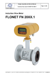
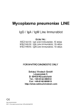
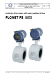
Product application, installation and service manual
FLOMIC FL 3005 – battery-powered ultrasonic flow meter
for direct installation in piping
ELIS PLZEŇ a. s.
Page 1 of 40
Battery-powered ultrasonic flow meter
for direct installation in piping
FLOMIC FL 3005
ELIS PLZEŇ a. s., Luční 15, P. O. BOX 126, 304 26 Plzeň, Czech Republic, tel.: +420/377 517 711, fax: +420/377 517 722
Es 90 398K/a
Product application, installation and service manual
ELIS PLZEŇ a. s.
FLOMIC FL 3005 – battery-powered ultrasonic flow meter
for direct installation in piping
Page 2 of 40
Contents
1. APPLICATION...........................................................................................................................................................3
2. FUNCTION PRINCIPLE ............................................................................................................................................3
3. TECHNICAL DESCRIPTION.....................................................................................................................................4
3.1. Terminology and symbols used in this manual..................................................................................................4
3.2. Meter description ...............................................................................................................................................5
3.3. Meter design......................................................................................................................................................9
3.3.1. Flow meter sensor............................................................................................................................9
3.3.2. Electronic unit UP 8.00.....................................................................................................................9
4. TECHNICAL PARAMETERS ....................................................................................................................................9
4.1. Flow velocity determination ...............................................................................................................................9
4.2. Technical specifications ..................................................................................................................................10
5. GENERAL RULES FOR FLOW METER APPLICATION .......................................................................................11
6. FLOW METER INSTALLATION .............................................................................................................................13
6.1. Meter assembly and installation principles ......................................................................................................13
6.1.1. Recommended assembly fixtures and tooling ...............................................................................14
6.1.2. Flow meter installation criteria........................................................................................................14
6.1.2.1. Measuring spot selection.......................................................................................................14
6.1.2.2. Necessary room for flow sensor installation ..........................................................................15
6.1.3. Preparatory and measuring operations on meter piping ................................................................15
6.1.3.1. Determination of OD of meter piping .....................................................................................15
6.1.3.2. Marking of top surface line ....................................................................................................16
6.1.3.3. Laying out of installation points .............................................................................................16
6.1.4. Fitting welded-on pieces into meter piping.....................................................................................18
6.1.5. Facing of seating surfaces on welded-on pieces ...........................................................................21
6.1.6. Determination of mechanical parameters of the meter sensor.......................................................22
6.1.6.1. Measuring ray angle..............................................................................................................22
6.1.6.2. Distance between the outer-end faces of welded-on pieces..................................................23
6.1.6.3. Inner diameter of meter piping...............................................................................................23
6.1.7. Flow meter sensor assembly .........................................................................................................24
6.1.8 External signal connections ............................................................................................................24
7. SETTING FLOW METER IN OPERATION .............................................................................................................25
7.1. Theoretical calibration .....................................................................................................................................25
7.2. Description of calibration procedure................................................................................................................25
7.2.1. TheoCalc program .........................................................................................................................26
7.2.2. CaliberFL program .........................................................................................................................27
7.2.3. Check on zero setting.....................................................................................................................30
8. METER OPERATION ..............................................................................................................................................30
8.1. Reading measured data from display..............................................................................................................30
8.2. Electrical outputs .............................................................................................................................................31
8.2.1. Impulse output................................................................................................................................31
8.2.2. Current output ................................................................................................................................32
8.3. Communication interface.................................................................................................................................32
8.3.1. Optical interface .............................................................................................................................32
8.3.2. RS 232 interface ............................................................................................................................33
8.3.2. M-Bus interface ..............................................................................................................................33
8.4. Communication modes....................................................................................................................................34
8.4.1. Optical probe + personal (notebook) computer..............................................................................34
8.4.2. RS 232 + personal (notebook) computer .......................................................................................34
8.4.2. RS 232 + GSM module ..................................................................................................................35
8.5. Error identification ...........................................................................................................................................35
8.6. Battery lifetime and replacement .....................................................................................................................36
9. WARRANTY AND POST-WARRANTY SERVICES ...............................................................................................37
9.1. Warranty services............................................................................................................................................37
9.2. Post-warranty services ....................................................................................................................................37
10. TESTING ...............................................................................................................................................................37
11. PACKAGING .........................................................................................................................................................37
12. PRODUCT ACCEPTANCE ...................................................................................................................................37
13. WARRANTY TERM AND CONDITIONS...............................................................................................................37
14. ORDERING PROCEDURE....................................................................................................................................38
ELIS PLZEŇ a. s., Luční 15, P. O. BOX 126, 304 26 Plzeň, Czech Republic, tel.: +420/377 517 711, fax: +420/377 517 722 Es 90 398K/a
Product application, installation and service manual
ELIS PLZEŇ a. s.
FLOMIC FL 3005 – battery-powered ultrasonic flow meter
for direct installation in piping
Page 3 of 40
1. APPLICATION
The FLOMIC battery-powered ultrasonic flow meter of the type series FL 3005 for direct installation into piping
is intended for measurements of instantaneous flow rate and of the total volume of water passed through fully
flooded piping. The flow meter includes hardware and software for communication with plant control systems.
The FLOMIC FL 3005 meter can be installed into existing steel piping with minimum modifications and
relatively low investment costs. The advantages of this solution are particularly evident in the cases of large piping
diameter where a flow meter sensor installation between flanges is far more expensive than a system using
“direct” sensor mounting.
2. FUNCTION PRINCIPLE
The FLOMIC FL 3005 meter uses a single-channel “transit-time” impulse measuring method where the flow
rate as the basic measured parameter is determined from the flight time of the ultrasonic signal between the
sensor probes.
The two ultrasonic probes installed into the fluid piping under specified angle operate in turns as a sender and
receiver (see Fig. 1).
Fig. 1 Principle of flow-rate measurement
It holds that, in the configuration shown in Fig. 1, ultrasonic ray propagates faster in the direction of the flowing fluid
that against it. Electronic converter evaluates the differences between the transit (passage) times of ultrasonic
waves sent in and against the fluid flow direction, determines the average flow velocity of the fluid and, taking into
account the parameters of the meter piping, calculates the value of instantaneous flow rate.
The above principle of flow rate measurement using ultrasonic ray can be described by the following equations:
v1 = c + v . cosα
[1]
v2 = c – v . cosα
[2]
t1 =
1
v1
[3]
t2 =
1
v2
[4]
ELIS PLZEŇ a. s., Luční 15, P. O. BOX 126, 304 26 Plzeň, Czech Republic, tel.: +420/377 517 711, fax: +420/377 517 722 Es 90 398K/a
Product application, installation and service manual
ELIS PLZEŇ a. s.
FLOMIC FL 3005 – battery-powered ultrasonic flow meter
for direct installation in piping
Page 4 of 40
where
v1
is ultrasonic ray velocity in the direction of fluid flow [m/s]
v2
is ultrasonic ray velocity against the direction of fluid flow [m/s]
t1
is passage time of ultrasonic ray sent in the fluid flow direction [s]
t2
is passage time of ultrasonic ray sent against the fluid flow direction [s]
c
is ultrasonic signal propagation velocity in the measured medium [m/s]
l
is distance between the face parts of ultrasonic probes [m]
v
is instantaneous value of the average velocity of the flowing medium [m/s]
α
is angle formed by the measuring ray and the longitudinal axis of the piping [deg]
After some modifications of equations [1] to [4], the average velocity of the fluid flowing through the piping can
be expressed as follows:
v=
1(t 2 − t1)
2.t1.t 2. cosα
[5]
For the flow rate it holds:
[6]
q = v.s.k (v)
where
2
s
is square section of the meter piping [m ]
k (v)
is correction coefficient related to the velocity profile of the fluid flowing through the meter piping
From equations [5] and [6] it follows that the flow rate of the measured medium is independent of either
sound propagation velocity in the measured medium or the medium pressure or temperature. The flow
rate only depends on the difference between the passage times of the ultrasonic signals sent between the
meter probes in and against the fluid flow direction, and on the mechanical arrangement of the flow meter
sensor, i.e. its dimensions and physical properties of the construction materials used.
For a flow meter installed directly in the existing piping it is therefore necessary to identify precisely the dimensions
and properties of the meter piping section. Upon installation of ultrasonic probes in the piping, all mechanical and
physical data on the sensor assembly need be reduced to electronic form and stored in the UP 8.00 electronic
control unit for the purposes of the so-called theoretical meter calibration.
3. TECHNICAL DESCRIPTION
3.1. Terminology and symbols used in this manual
abbreviated term or symbol
Meter piping
Meter piping is a section of technological piping system complying with the
requirements for flow meter installation
piping
Flow meter sensor
Meter piping section including ultrasonic probes
Flow-stabilising piping sections
To ensure correct functioning of the flow meter, the flow velocity profile in the
meter piping must be stable. This condition is met by locating the flow meter
sensor at a spot where there are straight piping sections of sufficient length at the
input and output sides of the meter sensor. The required stabilisation length is
given in multiples of the internal diameter (ID) of the meter piping.
Top surface line
The top surface line is defined as the section line common to a perpendicular
plane including the longitudinal axis of the piping and the outer piping surface.
sensor
Measuring ray
Measuring ray is ultrasonic signal (wave) propagating between the face parts of
ultrasonic probes along a line identical with the longitudinal axes of the probes.
pv
ray
ELIS PLZEŇ a. s., Luční 15, P. O. BOX 126, 304 26 Plzeň, Czech Republic, tel.: +420/377 517 711, fax: +420/377 517 722 Es 90 398K/a
Product application, installation and service manual
ELIS PLZEŇ a. s.
FLOMIC FL 3005 – battery-powered ultrasonic flow meter
for direct installation in piping
Page 5 of 40
Side surface line
The side surface line is defined as the section line common to a horizontal plane
including the longitudinal axis of the piping and the outer piping surface.
pb
Outer diameter (OD) of the meter piping
Do
Inner diameter (ID) of the meter piping
Di
Angle formed by the measuring ray and the longitudinal axis of the meter
piping
α
Ultrasonic probe
probe
Welded-on piece used as a holder for the ultrasonic probe
welded-on piece
Welding flange
flange
Rectification (alignment) pin
Distance between the face parts of ultrasonic probes
l
Distance between the outer-end faces of the welded-on pieces
L
Probe sealing thickness
p
Piping wall thickness
t
Length of the ultrasonic probe body
m
3.2. Meter description
The FLOMIC FL 3005 ultrasonic flow meter is an electronic device for measuring water flow rate in a fully
flooded piping. It consists of the battery-powered UP 8.00 electronic control unit and flow meter sensor including
two US 2.1 ultrasonic probes. In the standard configuration, the FL 3005 meter is suitable for application in piping
of nominal sizes DN 200 to DN 2,000; with angle α = 45° for piping sizes up to DN 800, and with angl e α = 60° for
larger sizes (see the schematic drawing below):
The meter software makes possible determination and display of the instantaneous flow rate values and those
of the total fluid volume passed through the meter sensor since the last resetting of the respective counter. The
flow meter is provided with a passive optically-isolated impulse output. The standard impulse length is 2ms. On
customer’s request, the setting can be changed to 40ms. The electronic control unit further includes the RS 232
communication interface.
ELIS PLZEŇ a. s., Luční 15, P. O. BOX 126, 304 26 Plzeň, Czech Republic, tel.: +420/377 517 711, fax: +420/377 517 722 Es 90 398K/a
Product application, installation and service manual
ELIS PLZEŇ a. s.
FLOMIC FL 3005 – battery-powered ultrasonic flow meter
for direct installation in piping
Page 6 of 40
The flow meter configuration can be extended to include optional features such as passive current output, data
archiving memory, M-Bus communication interface, GSM module and optical interface for data reading. On
special request, the ultrasonic probes can be supplied in the IP68 version.
The FLOMIC FL 3005 ultrasonic flow meter with ultrasonic probes to be fitted directly in the measured piping
consists of the following component parts:
1 pc. Electronic control unit (model UP 8.00, see Fig. 2)
2 pcs Ultrasonic probe (model US 2.1, see Fig. 3) including coaxial cable; the cable length should be specified in
the product order
2 pcs Welded-on piece (Fig. 4)
2 pcs Welding flange (Fig. 5)
2 pcs Probe sealing
Product application, installation and service manual (Es 90 398 K)
Theoretical calibration programs (Es 90 470 D and Es 90 499 D)
User program handbooks (Es 90 316 K and Es 90 318 K)
ELIS PLZEŇ a. s., Luční 15, P. O. BOX 126, 304 26 Plzeň, Czech Republic, tel.: +420/377 517 711, fax: +420/377 517 722 Es 90 398K/a
Product application, installation and service manual
ELIS PLZEŇ a. s.
FLOMIC FL 3005 – battery-powered ultrasonic flow meter
for direct installation in piping
Page 7 of 40
In the case of a meter installation by the customer, the delivery kit may include various optional measuring and
assembly fixtures, such as:
1 pc. Communication cable
1 pc. Protractor (Fig. 6)
1 pc. Protractor holder (Fig. 7)
1 pc. Strap piece (Fig. 8)
- Set of parts associated with the rectification pin:
1 pc. Protractor adaptor (Fig. 9)
1 pc. Milling adaptor I including milling tool and nut (Fig. 10)
1 pc. Milling adaptor II (Fig. 11)
- Set of connecting parts (see Fig. 12) in quantities given in the following table:
Piping size
DN 200
Connecting part, L = 250
1
Connecting part, L = 450
-
Connecting part, L = 850
-
DN 250
1
-
-
DN 300
1
-
-
DN 350
-
1
-
DN 400
-
1
-
DN 500
-
1
-
DN 600
-
-
1
DN 700
-
-
1
DN 800
-
-
1
DN 900
-
-
1
DN 1000
-
-
1
DN 1200
-
1
1
DN 1400
1
1
1
DN 1600
-
2
1
DN 1800
-
1
2
DN 2000
1
1
2
ELIS PLZEŇ a. s., Luční 15, P. O. BOX 126, 304 26 Plzeň, Czech Republic, tel.: +420/377 517 711, fax: +420/377 517 722 Es 90 398K/a
Product application, installation and service manual
ELIS PLZEŇ a. s.
FLOMIC FL 3005 – battery-powered ultrasonic flow meter
for direct installation in piping
Page 8 of 40
ELIS PLZEŇ a. s., Luční 15, P. O. BOX 126, 304 26 Plzeň, Czech Republic, tel.: +420/377 517 711, fax: +420/377 517 722 Es 90 398K/a
Product application, installation and service manual
ELIS PLZEŇ a. s.
FLOMIC FL 3005 – battery-powered ultrasonic flow meter
for direct installation in piping
Page 9 of 40
3.3. Meter design
3.3.1. Flow meter sensor
The flow meter sensor assembly consists of the meter piping and ultrasonic probes fitted into it.
3.3.2. Electronic unit UP 8.00
The flow meter control (and signal-processing) unit is accommodated in a plastic box attached to a steel plate
designed to be hung on a vertical support plate or wall. On the front panel of the box there are: flow meter name
and type designation, production series number, the manufacturer’s logo and trade name, back-lighted display
unit, membrane push button and optical probe window. At the bottom of the box under a removable lid there are
terminals for connecting cables. The bottom wall further includes four PG 7 grommets for cables of circular crosssection and diameters 3 to 6.5mm, and earthing bolt M4. Both the front panel and terminal lid are provided with
seals.
CAUTION: Prior to starting the meter operation, make sure that all grommets containing cables are properly
tightened and the unused grommets blinded.
CAUTION: When installed in the open air, the box containing electronic unit must be protected against direct
sunshine. However, the box must not be placed inside a sealed/unventilated cabinet.
Dimensional sketch of the electronic unit box
FLOMIC
E1 E2 E3 E4 E5
3
m l/s
x10 x10
ELIS PLZEN a.s.
OFFICIAL SEALS
INSTALLATION SEALS
4xO5,5
4. TECHNICAL PARAMETERS
4.1. Flow velocity determination
The basic parameter to be ascertained prior to installation of a flow meter is the range of operational flow rate
range expected in the given piping.
The flow rate is defined by the following formula:
[
q m 3 / hod
v[m / s ] = 353.
Di2 [mm]
]
Di is ID of the meter piping
q is measured flow rate
v is flow velocity
The fluid flow rate in the meter piping must be within the range of 3 to 6 m/s.
where
ELIS PLZEŇ a. s., Luční 15, P. O. BOX 126, 304 26 Plzeň, Czech Republic, tel.: +420/377 517 711, fax: +420/377 517 722 Es 90 398K/a
Product application, installation and service manual
ELIS PLZEŇ a. s.
FLOMIC FL 3005 – battery-powered ultrasonic flow meter Page 10 of 40
for direct installation in piping
4.2. Technical specifications
Piping ID DN
200 to 2,000
Measuring ray angle α
for DN 200 to DN 800 - 45
o
for DN > 800 to DN 2,000 - 60
± 2% of the measured flow rate within the range of 5 to 100% qs
o
Measurement accuracy
(qs- maximum flow rate at the flow velocity of 6 m/s)
Rated (nominal) pressure of measured fluid
PN
max. 40
Temperature of measured fluid
0 to +150 C
Ambient temperature
+5 to +55 C
Ambient humidity
max. relative humidity 80%
Storage temperature
-10 to +70 C at relative humidity not exceeding 70%
Protection class
- electronic unit UP 8.00
IP 65
- ultrasonic probe US 2.1
IP 54
Ultrasonic probes
model US 2.1, 2 pieces, manufacturer: ELIS PLZEŇ a.s.
Probe installation
direct fitting into the meter piping (see the product manual)
Connecting cable to probe US 2.1
max. length 20m
Difference in probe cable lengths
Not exceeding 0.1m
o
o
o
Electronic unit UP 8.00
- overall dimensions
- weight
- power supply
Fluid flow velocity range
230 x 217 x 85mm
1.5kg
1x Li battery 3.6V / 16.5Ah
2x (or 3x – for DN1,400 to 2,000) alkali batteries 9V / 0.5A
Battery lifetime: 4 years
3 to 6 m/s
Display unit
8-character LCD
Outputs
passive impulse output U = 3 to 30V, Imax = 10mA
Optional features/accessories
communication interface RS 232
passive current output 4 to 20mA, Umax = 24V
data archiving memory
archive data reading via GSM module
optical interface function including optical probe and ArchTerm
program
communication interface M-BUS
ultrasonic probes with protection class IP 68
Qmax and impulse constants (litres per impulse) for particular piping sizes
200
250
300
350
400
450
500
550
600
650
700
750
Qmax [m /h]
600
1000
1500
2000
2500
3500
4500
5000
6000
7000
8000
9000
Imp [l/imp]
500
500
500
1000
1000
1000
2000
2000
2000
5000
5000
5000
DN
800
900
1000
1100
1200
1300
1400
1500
1600
1800
2000
10000
12000
14000
16000
18000
20000
22000
24000
25000
30000
36000
5000
10000
10000
10000
10000
10000
10000
10000
10000
10000
10000
DN
3
3
Qmax [m /h]
Imp [l/imp]
ELIS PLZEŇ a. s., Luční 15, P. O. BOX 126, 304 26 Plzeň, Czech Republic, tel.: +420/377 517 711, fax: +420/377 517 722 Es 90 398K/a
Product application, installation and service manual
ELIS PLZEŇ a. s.
FLOMIC FL 3005 – battery-powered ultrasonic flow meter Page 11 of 40
for direct installation in piping
5. GENERAL RULES FOR FLOW METER APPLICATION
When using an ultrasonic flow meter in a piping containing a particular fluid, certain conditions need be met to
ensure correct measurements. The limiting operational parameters of the fluid (i.e. temperature, pressure and flow
velocity) as well as the mechanical design and properties of the meter sensor (flow stabilisation piping sections
before and after sensor, complete flooding of the sensor cavity at all times, elimination of cavitation effects and
fluid foaming) must comply with the requirement for steady fluid flow with no gas bubbles or foam appearing in the
piping. Such conditions are different for various types of fluid and need be correctly identified for each specific
measuring spot and/or technological piping system.
CAUTION: Ultrasonic flow meter of a specific DN must not be used in piping of lesser sizes (smaller DN).
Selection of measuring spots in piping systems must be done in observance of certain basic rules. Incorrect
placement of meter may result in deteriorated measurement stability or precision. To the extent possible, avoid
meter placement after valves or pumps in piping. The recommended minimum lengths of straight piping sections
before and after the meter are 5DN and 3DN, respectively (see Fig. 13).
5 DN
3 DN
FLOW DIRECTION
Fig. 13 Recommended fluid stabilisation piping section before and after the ultrasonic flow meter
If there is a pump in the piping, the recommended length of straight piping section between the pump and sensor
is 20DN. If there is at the sensor input side a fully open valve, the recommended length of straight piping section is
10DN. If it is a valve with fluid control function, the straight piping section should be at least 40DN long (see Fig.
14).
20 DN
FLOW DIRECTION
10÷40 DN
FLOW DIRECTION
Fig. 14 Straight piping sections to eliminate the effect of disturbances on the sensor input side
ELIS PLZEŇ a. s., Luční 15, P. O. BOX 126, 304 26 Plzeň, Czech Republic, tel.: +420/377 517 711, fax: +420/377 517 722 Es 90 398K/a
Product application, installation and service manual
FLOMIC FL 3005 – battery-powered ultrasonic flow meter Page 12 of 40
for direct installation in piping
ELIS PLZEŇ a. s.
In the cases of a disturbance after the sensor, the required minimum length of straight piping section is 3DN (see
Fig. 15).
3 DN
3 DN
FLOW DIRECTION
FLOW DIRECTION
Fig. 15 Straight piping sections to eliminate the effect of disturbances on the sensor output side
If complete flooding of the whole piping system cannot be guaranteed at all times, the flow sensor should be
located at bottom pockets in the piping where this requirement is met under all circumstances and operational
conditions (see Fig. 16).
3
DN
5 DN
5
3 DN
DN
FL
OW
CT
RE
I
D
N
IO
FLOW DIRECTION
Fig. 16 Sensor placement in bottom pockets ensuring complete flooding at all times
FLOW DIRECTION
Where the meter sensor is to be placed in a vertical piping section, the flow direction shall be upwards (see Fig.
17).
Fig. 17 Sensor fitted into a vertical piping section
ELIS PLZEŇ a. s., Luční 15, P. O. BOX 126, 304 26 Plzeň, Czech Republic, tel.: +420/377 517 711, fax: +420/377 517 722 Es 90 398K/a
Product application, installation and service manual
ELIS PLZEŇ a. s.
FLOMIC FL 3005 – battery-powered ultrasonic flow meter Page 13 of 40
for direct installation in piping
FLOW DIRECTION
To ensure correct measurement at all times, make sure that the sensor flow profile is always completely filled with
the measured fluid. Avoid sensor placement at top pockets or in vertical piping sections with the flow direction
downwards, in particular in the cases of piping sections discharging fluid to open tanks (see Fig. 18).
FLOW DIRECTION
Fig. 18 Examples of incorrect sensor placement
6. FLOW METER INSTALLATION
6.1. Meter assembly and installation principles
The flow meter assembly and installation must be done in strict observance of the rules and recommendations
in this product manual.
To minimise electromagnetic interference, make sure that the signal cables are laid at least 25cm away from
the power cables feeding other electrical equipment. Shielded conductors are recommended to use for all signal
lines. Any extension connections between signal conductors must be soldered and the soldered joints protected by
suitable installation boxes against climatic and mechanical stresses. All cables must be led outside the thermal
insulation layers on piping (if applicable). Proper earthing is required for the electronic unit. To do that, use earthing
2
conductor of cross section 4mm or larger and connect the earthing bolt on the electronic unit box with the meter
piping at the measuring location (see Fig, 19).
2
min.4mm
FLOMIC
ELIS PLZEN a.s.
Fig. 19
ELIS PLZEŇ a. s., Luční 15, P. O. BOX 126, 304 26 Plzeň, Czech Republic, tel.: +420/377 517 711, fax: +420/377 517 722 Es 90 398K/a
Product application, installation and service manual
ELIS PLZEŇ a. s.
FLOMIC FL 3005 – battery-powered ultrasonic flow meter Page 14 of 40
for direct installation in piping
6.1.1. Recommended assembly fixtures and tooling
Apart from special measurement and assembly fixtures listed in Section 3.2 above, you will need the following:
Emery cloth No 60
Water level, min. length 400mm
Flexible steel ruler, length 1,000mm
Steel measuring rule, length 3m
Steel measuring tape, flat, min. length 10m
Slide rule
Marking awl
Hammer
Centre punch
Steel angle 40 x 40mm, length 0.6Do
Sheet of paper, dimensions 1.1Do x 1.8Do
Drawing tools (setsquare, drawing pen etc.)
White chalk
Black spirit marker, ø 1mm
Rubber rope bandages
Thread cap for welded-on piece, G 1“
Half-round file
Steel pin ø 7mm, length 200mm
Side spanner, size 19mm, 2 pieces
Calculator with trigonometric and other mathematical functions Electric welding equipment, 250A including
accessories
Oxy-acetylene equipment and cutting torches
Hand-held angle grinder, grinding wheel ø 125mm
Hand-held electric drill, max. chucking diameter 12mm
6.1.2. Flow meter installation criteria
6.1.2.1. Measuring spot selection
When selecting the piping section where the flow-meter sensor is to be installed (see also Chapter 5), make
sure that the surface quality of the piping, in particular any irregularities of shape, deformations, the position and
surface finish of welding joints, whether longitudinal, helical or others, is such that it allows for accurate
determination of the angle formed by the measuring ray and the longitudinal axis of the piping.
ELIS PLZEŇ a. s., Luční 15, P. O. BOX 126, 304 26 Plzeň, Czech Republic, tel.: +420/377 517 711, fax: +420/377 517 722 Es 90 398K/a
Product application, installation and service manual
ELIS PLZEŇ a. s.
FLOMIC FL 3005 – battery-powered ultrasonic flow meter Page 15 of 40
for direct installation in piping
6.1.2.2. Necessary room for flow sensor installation
The flow sensor installation in the existing piping (using the fixtures and tooling specified in this manual)
requires free room of at least 900mm to the sides of the welded-on pieces and in the direction of the measuring
ray (see Fig. 20).
Fig. 20 Required free room in the vicinity of welded-on pieces
In the ideal case, the ultrasonic ray axis should lie in the horizontal plane. Should the spatial limitations
necessitate selection of another angle of the ultrasonic ray, the method of marking the key installation points on
the piping needs be modified accordingly. The manufacturer’s specifications require that the angle formed by the
ultrasonic ray and the horizontal plane should not exceed 30°.
The preparatory steps for the sensor installation, determination of the mechanical parameters of the measuring
spot and the installation process itself as described below have been designed for application at the customer’s
plant and operating conditions.
6.1.3. Preparatory and measuring operations on meter piping
The surface of the meter piping must be clean and smooth; any adhering dirt, rough irregularities of shape,
corrosion products and traces of paint must be removed.
6.1.3.1. Determination of OD of meter piping
Each of the two methods described below can be used:
Diameter calculation from piping circumference
This method is suitable for piping of larger sizes. Measure the piping circumference using a flat steel
measuring tape.
The outer diameter of the meter piping can then be calculated as follows:
Do =
O
π
where O is piping circumference, being the average value of two circumference measurements taken at the
locations where the welded-on pieces are to be attached.
ELIS PLZEŇ a. s., Luční 15, P. O. BOX 126, 304 26 Plzeň, Czech Republic, tel.: +420/377 517 711, fax: +420/377 517 722 Es 90 398K/a
Product application, installation and service manual
ELIS PLZEŇ a. s.
FLOMIC FL 3005 – battery-powered ultrasonic flow meter Page 16 of 40
for direct installation in piping
Direct diameter measurement using diameter gauge Take three diameter measurements, equally spaced
(120° apart) along the piping circumference, at eac h of the two intended positions of the welded-on pieces.
Calculate the outer piping diameter as the average value of the average diameter values measured at the
positions of the welded-on pieces:
D1 + D 2 + D3
3
D + Do 2
Do = o1
2
Do1 =
Do 2 =
D 4 + D5 + D 6
3
Where D1 to D6 are the measured OD values on the meter piping.
6.1.3.2. Marking of top surface line
Use water level to identify the top surface line on the meter piping (see Fig. 20). The two points of the surface top
line (a1, a2) are the points of contact between the piping and water level after the water level has been set in the
horizontal position. The distance between points a1 and a2 is recommended to be selected equal to the piping
diameter (b = D0). Use a steel ruler to draw the top surface line pv.
Fig. 20 Top surface line marking on meter piping.
6.1.3.3. Laying out of installation points
To identify and mark the key sensor installation points on the meter piping, select and use one of the following two
methods. The indirect method is less time-consuming and therefore preferred in most practical situations.
Direct method – Measurements are taken and installation points marked directly on the meter piping
Indirect method – The installation points are transferred onto the piping by means of a template drawn on a sheet
of paper.
ELIS PLZEŇ a. s., Luční 15, P. O. BOX 126, 304 26 Plzeň, Czech Republic, tel.: +420/377 517 711, fax: +420/377 517 722 Es 90 398K/a
Product application, installation and service manual
ELIS PLZEŇ a. s.
FLOMIC FL 3005 – battery-powered ultrasonic flow meter Page 17 of 40
for direct installation in piping
Direct method:
Draw two parallel surface lines pb1 and pb2 at the distance of
π .D o
4
, i.e. Do x 0.7854 left and right of the top
surface line (see Fig. 21).
Fig. 21 Laying out of key installation points
On the top surface line pv mark two points (X1 and X2) at the distance of c. Distance c is defined by the formula
c=
Do
, from which it follows:
tgα
for α = 45°
c = D o; and
for α = 60°
c = D o x 0.5774.
From points X1 and X2 on the top surface line lead perpendicular lines along the piping surface towards the
parallel lines pb1and pb2. The intersection points (M1 and M2) are the points where the ultrasonic ray is to penetrate
the surface of the meter piping. The points M1 and M2 serve the purpose of accurate setting of the mounting
positions of the welding flanges. Identify the positions of points M1 and M2 by crosses of lines of at least 100mm
each and mark the cross line ends by centre punch dots (see Fig. 21).
ELIS PLZEŇ a. s., Luční 15, P. O. BOX 126, 304 26 Plzeň, Czech Republic, tel.: +420/377 517 711, fax: +420/377 517 722 Es 90 398K/a
Product application, installation and service manual
ELIS PLZEŇ a. s.
FLOMIC FL 3005 – battery-powered ultrasonic flow meter Page 18 of 40
for direct installation in piping
Indirect method:
Prepare a template of installation points using a sheet of paper of minimum dimensions 1.1.Do x 1.8.Do.
A. Draw a centre line (pv) and mark on it points X1 and X2 at the distance of
Do
(for α = 45° it is D o, for α = 60°
tgα
the distance of Do x 0.5774).
B. At points X1 and X2 draw parallel lines perpendicular to central line pv, one on each side, and mark on them
points M1 and M2 at the distance of Do x 0.7854. Identify points M1 and M2 by crosses of lines of minimum
length 100mm (see Fig. 22).
Fig. 22 Paper template
C. Lay the paper template on the piping so that the central line pv coincides with the top surface line marked on the
meter piping. Then, using a centre punch, transfer all key installation points including the ends of the cross
lines onto the piping.
D. Using a drawing awl, mark the crosses defining points M1 and M2 on the piping surface as with the direct
method above.
6.1.4. Fitting welded-on pieces into meter piping
A. Using oxy-acetylene torch, cut circular holes in the meter piping of diameter 60mm and centres at points M1 and
M2. Prevent the cut-out section from falling inside the piping and save them; they will be needed to determine
the inner diameter of the meter piping. In the cases of pipe with the wall thickness t in excess of 5mm (for α =
45°), or t greater than 15mm (for α
= 60°), the holes of diameter 60mm need be modifie d so that the
welded-on pieces can be inserted into the piping as shown in Fig. 23. Make sure that both the inner and our
edges of the holes are smooth and clean.
B. Ground the edges of the cut-out sections without damaging the surface parts. Then use a slide rule to
determine the thickness of the pipe wall.
ELIS PLZEŇ a. s., Luční 15, P. O. BOX 126, 304 26 Plzeň, Czech Republic, tel.: +420/377 517 711, fax: +420/377 517 722 Es 90 398K/a
Product application, installation and service manual
ELIS PLZEŇ a. s.
C.
FLOMIC FL 3005 – battery-powered ultrasonic flow meter Page 19 of 40
for direct installation in piping
Slide the welding flanges onto the welded-on pieces and adjust their positions with respect to the setting
marks. The insertion depth shall be such that the bottom part of the welded-on piece is flush with the internal
surface of the meter piping (see Fig. 23). Mark on the welded-on piece the correct depth of insertion of the
same into the flange.
Fig. 23 Assembly of welded-on pieces
D. Assemble the rectification pin of the following component parts:
milling adaptor I,
connecting parts selected to fit the piping size, and
protractor adaptor.
The parts must be properly tightened to form a stable whole.
The rectification pin assembly parts and their fitting are shown in the following picture.
ELIS PLZEŇ a. s., Luční 15, P. O. BOX 126, 304 26 Plzeň, Czech Republic, tel.: +420/377 517 711, fax: +420/377 517 722 Es 90 398K/a
Product application, installation and service manual
ELIS PLZEŇ a. s.
FLOMIC FL 3005 – battery-powered ultrasonic flow meter Page 20 of 40
for direct installation in piping
Fig. 24 Rectification pin assembly parts
Insert the assembled rectification pin into the holes in the meter piping is the direction indicated by the arrow in
Fig. 24.
E.
From both sides of the meter piping, slide the welding flanges and welded-on pieces on the rectification pin.
The flange marks must be positioned against the cross marks drawn on the meter piping. The welded-on
pieces shall be set to the desired position with respect to the assembly marks. Check the ease of
movement of the rectification pin in the welded-on pieces.
F. Check the correct setting of one of the flanges with respect to the respective cross mark and fix its position by
four point welds. Repeat the procedure with the other flange.
G.
Check the play of the rectification pin in the welded-on pieces (it shall be easily rotated and moved in the
axial direction). Apply fillet welds to fix the positions of the flanges on the piping.
H.
Using the assembly marks, set the correct positions of the welded-on pieces in the flanges and fix them by
several point welds.
I. Check the play of the rectification pin in the welded-on pieces again. Apply fillet welds to secure positions of the
welded-on pieces in the respective flanges.
Comment:
When performing the welding operations with the welded-on pieces slid on the rectification pin, make sure that the
functional parts of the welded-on pieces cannot be damaged by the flying sparks and protect them by suitable
covers or nuts. Should it be found that, at any time during the welding operations, the rectification pin has lost its
desired play (free rotation and displacement in the holes in the welded-on pieces), the reason for that condition
must be established and the defect removed by slight knocking on the welded-on pieces (with the thread
protected).
It is recommended to check the rectification pin play after each welding operation.
ELIS PLZEŇ a. s., Luční 15, P. O. BOX 126, 304 26 Plzeň, Czech Republic, tel.: +420/377 517 711, fax: +420/377 517 722 Es 90 398K/a
Product application, installation and service manual
ELIS PLZEŇ a. s.
FLOMIC FL 3005 – battery-powered ultrasonic flow meter Page 21 of 40
for direct installation in piping
6.1.5. Facing of seating surfaces on welded-on pieces
To ensure a perfect alignment of the ultrasonic probes, the seating surfaces on the welded-on pieces need be
end-faced. To do that, fit a milling tool onto the milling adaptor I (fitted onto the rectification pin) and secure its
position by a nut (see Fig. 25).
Fig. 25 Facing of the seating surfaces on the welded-on pieces
Grease slightly (with vaseline) those parts of the rectification pin that will rotate in the welded-on pieces. Using
a hand-held drilling machine with controlled speed, rotate the rectification pin in the clockwise direction and face
the seating surface on the welded-on piece. Then remove the rectification pin assembly, insert it into the weldedon pieces in the opposite direction and face-mill the other seating surface.
Should there be insufficient room on the other side of the piping, do not remove the rectification pin but replace
the protractor adaptor by milling adaptor II with a milling tool attached, secure the threads against turning (using
Loctite or similar bonding agent) and face the (otherwise inaccessible) seating surface by pulling the rectification
pin out and rotating it in the counter-clockwise direction (see Fig. 26).
After the milling operation, remove the milling tool and nut and leave the rectification pin inserted in the weldedon pieces on the meter piping.
Fig. 26 Facing of the seating surface on the inaccessible welded-on piece
ELIS PLZEŇ a. s., Luční 15, P. O. BOX 126, 304 26 Plzeň, Czech Republic, tel.: +420/377 517 711, fax: +420/377 517 722 Es 90 398K/a
Product application, installation and service manual
ELIS PLZEŇ a. s.
FLOMIC FL 3005 – battery-powered ultrasonic flow meter Page 22 of 40
for direct installation in piping
6.1.6. Determination of mechanical parameters of the meter sensor
To achieve the specified measurement precision of the FLOMIC FL 3005 flow meter, the mechanical parameters
(dimensions) of the meter piping need be determined with the tolerances of ±1 ‰.
Example: For DN 500 meter piping with the measurement ray angle α = 45° and the distance between the
outer-end faces of the welded-on pieces L = 850mm, the mechanical parameters need be determined with the
dimensional errors not exceeding:
∆L =
L
= 0.85mm
1,000
∆D1 =
D1
= 0.5mm
1,000
Angle α needs be determined with the precision of ∆α = 0.1° irrespective of the meter piping size (DN).
6.1.6.1. Measuring ray angle
A.
Remove all corrosion products, traces of paint and other contamination from the piping surface where the
strap piece is to be laid.
B. Place the strap piece on the piping so that its longitudinal axis is parallel to the side surface line on the piping.
Use rubber bandages to hold the strap piece firmly in position on the piping surface (see Fig. 27).
C. Attach a protractor onto the protractor adaptor mounted at one of the rectification pin ends.
D. The angle α measurements (three measurements at each of the welded-on piece positions) shall be performed
in the plane defined by the longitudinal piping axis and the respective side surface line. Between the
measurements knock slightly on the strap piece or move it to the side and back to ensure its correct seating.
E. The value of α shall then be determined as the arithmetic average of all measurements taken:
α=
α1 + α 2 + α 3 + α 4 + α 5 + α 6
6
where α1 to α3 are measured angles formed by the rectification pin and the surface of the meter piping at one of
the welded-on pieces, and
α4 to α6 are angles formed by the rectification pin and the surface of the meter piping at the other weldedon piece.
Fig. 27 Determination of the measuring ray angle
ELIS PLZEŇ a. s., Luční 15, P. O. BOX 126, 304 26 Plzeň, Czech Republic, tel.: +420/377 517 711, fax: +420/377 517 722 Es 90 398K/a
Product application, installation and service manual
ELIS PLZEŇ a. s.
FLOMIC FL 3005 – battery-powered ultrasonic flow meter Page 23 of 40
for direct installation in piping
6.1.6.2. Distance between the outer-end faces of welded-on pieces
Depending on the given arrangement and space available (the inner diameter of the meter piping, free room in
the vicinity of the welded-on pieces etc.), the distance L between the outer-end faces of the welded-on pieces can
be determined either by direct measurement using a suitable gauge or steel rule inserted by means of an auxiliary
pin into the welded-on pieces, or indirectly, by making marks on the rectification pin and measuring the distance
between them after removal of the pin from the welded-on pieces (see Fig. 28).
The auxiliary pin used to insert a steel rule into the meter piping should be of a smaller diameter than the
rectification pin. Such pin is not included in the delivery kit.
Fig. 28 Determination of distance L
6.1.6.3. Inner diameter of meter piping
The meter piping is integral part of the piping system where flow measurements are to be performed. The ID of
meter piping can be determined by calculation as follows:
Di = Do - 2 t
where t is the pipe wall thickness.
The OD of the meter piping (D0) was determined earlier using the procedure outlined in Section 6.1.3.1 above.
The pipe wall thickness t should be determined by measurement on the cut-out sections acquired when holes
were cut in the pipe wall for fitting of the welded-on pieces. Each section shall be measured three times at spots
120° apart and the value t calculated as the averag e of the six measurements taken. Regarding conditioning of the
cut-out sections prior to measurement see Section 6.1.4 - B.
ELIS PLZEŇ a. s., Luční 15, P. O. BOX 126, 304 26 Plzeň, Czech Republic, tel.: +420/377 517 711, fax: +420/377 517 722 Es 90 398K/a
Product application, installation and service manual
FLOMIC FL 3005 – battery-powered ultrasonic flow meter Page 24 of 40
for direct installation in piping
ELIS PLZEŇ a. s.
6.1.7. Flow meter sensor assembly
The preceding assembly and measurement operations have yielded the following basic sensor parameters
necessary to perform the so-called theoretical meter calibration:
- measuring ray angle α
- distance L between the outer-end faces of the welded-on pieces;
- inner piping diameter Di
Upon finishing the measurements, the sensor assembly can be completed. Insert the ultrasonic probes including
sealing into the welded-on pieces and tighten the holding nuts using the torque of 150 Nm.
Connect coaxial cables from the probes to terminal strip X1 of the associated electronic control unit (see Fig. 29).
The meter is now ready for theoretical calibration.
6.1.8 External signal connections
Remove the lid held in position by two M4 screws at the bottom of the front panel of the UP 8.00 electronic unit
box to gain access to the terminal strip for sensor probe cables and output signals.
COMUNICATION
INTERFACE M-BUS
COMUNICATION INTERFACE RS 232
2
3
4
1
2
3
4
RS 232
PROBE 2
PROBE 1
-Rs +Rs Rx Tx
5
6
7
8
X10
9 10 11 12 13 14
1
2
3
4
5
Pulse output
power supply
1k
-Rs
÷ 1M
+ U=5÷30V
- Imax.=10mA
-IMP
PE PE 1
X10
+Rs
M-BUS
+IMP
X1
Pulse output
(ext. power supply)
XS
+I
-I
Current output power
supply U =10÷24V
+
Current output
(ext. power supply)
4÷20mA
GROUNDING
Fig. 29 Input and output signal connections of the UP 8.00 electronic unit
ELIS PLZEŇ a. s., Luční 15, P. O. BOX 126, 304 26 Plzeň, Czech Republic, tel.: +420/377 517 711, fax: +420/377 517 722 Es 90 398K/a
Product application, installation and service manual
ELIS PLZEŇ a. s.
FLOMIC FL 3005 – battery-powered ultrasonic flow meter Page 25 of 40
for direct installation in piping
To ensure correct functioning of the flow meter, ultrasonic probes 1 and 2 must be connected as shown in Fig. 30
(probe 1 must be closer to the output end of the sensor and probe 2 on the input side). The probe cables are
marked accordingly.
Fig. 30 Probe marking
7. SETTING FLOW METER IN OPERATION
7.1. Theoretical calibration
The relationship between flow rate q and flow velocity v is given by the general formula q = f (v).
Function f depends on the meter piping ID, the inner surface roughness, viscosity of the measured fluid and, to
some extent, the delay of the probe excitation signal in the coaxial cable connecting the probe and the electronic
control unit.
In practical situations, the theoretical meter calibration is done using the TheoCalc and CaliberFL programs
generating the q = f (v) function for all flow rate values.
7.2. Description of calibration procedure
The necessary equipment and data:
PC and calibration programs TheoCalc 1.0 and CaliberFL 2.3
Communication cable or optical reading probe
Meter piping data: maximum flow rate
Inner diameter
distance between the face parts of the welded-on pieces
probe length
angle formed by probes and longitudinal piping axis
length of the probe cables
multiplier (10 or 100 – shown on the front panel under the display unit)
The theoretical calibration consists of three steps:
ELIS PLZEŇ a. s., Luční 15, P. O. BOX 126, 304 26 Plzeň, Czech Republic, tel.: +420/377 517 711, fax: +420/377 517 722 Es 90 398K/a
Product application, installation and service manual
ELIS PLZEŇ a. s.
FLOMIC FL 3005 – battery-powered ultrasonic flow meter Page 26 of 40
for direct installation in piping
7.2.1. TheoCalc program
Start the TheoCalc program and fill out the table in Fig. 31. At this stage, the PC need not be connected to the
meter control unit.
Fig. 31
Table data entry instruction: enter data into blue fields; double-click the mouse to move between fields.
The following data need be entered:
Inner diameter – inner diameter of the meter piping
Qmax – maximum flow rate
Surface roughness – inner piping surface roughness; recommended value 0.2
Distance weld-on p. – distance between face parts of welded-on pieces
Probe length
Angle of probes – angle formed by probes and longitudinal piping axis
Cable length – length of coaxial cables connecting probes and el. unit
Recalculate – multiplier (shown on the electronic unit rating plate)
Upon entering all required data depress key “Generate A0 and table V-Q” to perform calculations and fill out the
bottom table. Then click on “File”, “Write” and store the data file. The file name should consist of the first five digits
of the production series number (without slash and the production year) and the “btp” suffix.
ELIS PLZEŇ a. s., Luční 15, P. O. BOX 126, 304 26 Plzeň, Czech Republic, tel.: +420/377 517 711, fax: +420/377 517 722 Es 90 398K/a
Product application, installation and service manual
ELIS PLZEŇ a. s.
FLOMIC FL 3005 – battery-powered ultrasonic flow meter Page 27 of 40
for direct installation in piping
7.2.2. CaliberFL program
Using coaxial cable or optical probe, connect your PC to the electronic control unit and start the CaliberFL
program. With the table shown in Fig. 32 displayed, check the agreement between the port number displayed in
the table and the number of the port to which communication channel is connected. Should it be necessary to
change the port number, stop and re-initialise the CaliberFL program.
Please note that:
- unless communication is in operative condition, the menu items are not accessible;
- to rewrite data in a particular field, double-click on such field
- if Qmax is changed, the program must be reset
- do not let the program run without the communication channel connected/operative
- should communication appear not to work properly, close and re-initialise the program.
Fig. 32
ELIS PLZEŇ a. s., Luční 15, P. O. BOX 126, 304 26 Plzeň, Czech Republic, tel.: +420/377 517 711, fax: +420/377 517 722 Es 90 398K/a
Product application, installation and service manual
ELIS PLZEŇ a. s.
FLOMIC FL 3005 – battery-powered ultrasonic flow meter Page 28 of 40
for direct installation in piping
Click on “Calibration” to have the following empty table displayed (see Fig. 33).
Fig. 33
Using the following procedure, copy into this table the data created by the TheoCalc program. Click on “File” and
“Open” to access the screen in Fig. 34. Select the file created by TheoCalc and click on “Open” to transfer it to the
previous table shown in Fig. 33.
Fig. 34
ELIS PLZEŇ a. s., Luční 15, P. O. BOX 126, 304 26 Plzeň, Czech Republic, tel.: +420/377 517 711, fax: +420/377 517 722 Es 90 398K/a
Product application, installation and service manual
ELIS PLZEŇ a. s.
FLOMIC FL 3005 – battery-powered ultrasonic flow meter Page 29 of 40
for direct installation in piping
In the filled-out table (see Fig. 35) select and double-click on the field “Insensivity near zero” and enter the
required insensitivity (typically 20; values less than 10 are not recommended). Then fill out the field “Pulse
number”, taking into account the given multiplier (for example: for desired impulse number 10,000 l/min and
multiplier 100 enter 100). The maximum Pulse number permitted is 110. Then click on software key “Calculate to
inner units” whereby the key “Write table to EEPROM” will be enabled. Use this key to start the programming
procedure. When this is completed, close the table.
Fig. 35
Now, provided the meter piping is fully flooded, the flow meter will start operation – the E1 field signalling error on
the display will go dark and, provided the fluid in the piping is flowing, the meter will display the actual flow rate.
ELIS PLZEŇ a. s., Luční 15, P. O. BOX 126, 304 26 Plzeň, Czech Republic, tel.: +420/377 517 711, fax: +420/377 517 722 Es 90 398K/a
Product application, installation and service manual
ELIS PLZEŇ a. s.
FLOMIC FL 3005 – battery-powered ultrasonic flow meter Page 30 of 40
for direct installation in piping
7.2.3. Check on zero setting
If you can arrange for zero flow rate (by closing the valves before and after the meter or by switching off the fluid
pump), check the flow-rate zero setting. Run the CaliberFL program again and display the table in Fig. 36.
Fig. 36
Click on the key “Clear average speed” and reset the readings “Average flow speed” and “Average counter”
(the corresponding number of the measurements taken). The reading “Flow speed” should be within the limits of 10 mm/s and +10 mm/s; should any of these limit values be exceeded, check the tightness of closed valves.
When the reading at “Average counter” reaches about 120, click on the key “Zero adjustment” to modify the
reading at “Symmetry setting”. About six seconds later, repeat the procedure of the zero setting check. Now the
reading at “Average flow speed” should not be greater than ± 2mm. The phenomenon called “rocking” can be
observed with long piping where the steady state after the valve closure may take several minutes to attain. In
such a case wait till the reading at “Flow speed” drops below 4 mm/s and then perform the zero setting check. If
the condition of zero flow rate cannot be ensured, the zero setting procedure is not performed.
8. METER OPERATION
8.1. Reading measured data from display
3
3
The 8-character display unit shows the values of flow rate in m /hour or the total fluid volume in m passed
through the meter sensor. The figures on display must be multiplied by appropriate coefficients (see the table
below). The displayed value of instantaneous flow rate has certain time delay; it is calculated as the average value
of the last six measurements taken over the last six seconds. Such floating average values are displayed and
brought to the meter outputs. The delay due to the average value calculation may become noticeable in the cases
of rapid flow-rate increase and decrease. Should an error in the meter function be detected, the corresponding
error massage is displayed. Because of the power-saving mode of the battery supply, the push-button switching
ELIS PLZEŇ a. s., Luční 15, P. O. BOX 126, 304 26 Plzeň, Czech Republic, tel.: +420/377 517 711, fax: +420/377 517 722 Es 90 398K/a
Product application, installation and service manual
ELIS PLZEŇ a. s.
FLOMIC FL 3005 – battery-powered ultrasonic flow meter Page 31 of 40
for direct installation in piping
commands changing the display modes from flow-rate to total fluid volume and back can be given no faster than
once a second. It is therefore recommended that, to ensure correct switching function, the control push-button be
held depressed for at least one second and the period between two successive switching commands be longer
than one second. The position of the decimal point on the display (see Fig. 37) depends on the measured total
fluid volume and the applicable multipliers (see the table below).
Decimal point
for 8 digit values
Decimal point
for values
up to 5 digits
Decimal point
for 7 digit values
Decimal point
for 6 digit values
Fig. 37 Decimal point positions on the display
CAUTION: The display readings and values read from the archive files must be multiplied by one of the
coefficients shown in Table 4 below. The applicable coefficient is given on the front panel under
3
3
the respective units of measurement (m , m /h; see the dimensional drawing in Section 3.3.2 above).
Piping size (DN)
200 to 450
500 to 2,000
x 10
x 100
3
Coefficient
m /h
3
m
8.2. Electrical outputs
8.2.1. Impulse output
The passive impulse output is a standard feature of all meter versions. It is an optically isolated output connected
to terminals 11 and 12 of the output terminal strip X10 (see Fig. 29, Section 6.1.8) with maximum loading capacity
of 10 mA. The impulse width preset at the manufacturing plant is 2 ms. It can be reset at any time to 40 ms using
jumper J5 (see Fig. 38).
Impulse output setting by means of jumper J5:
Jumper J5
Impulse width
Impulse level
External voltage
Loading current range
Loading resistor
1–2
2 ms
L(0V)
3 to 30 V
0.003 to 10 mA
1 kΩ to 1 MΩ
2–3
40 ms
L ( 0V )
5 to 30 V
0.1 to 10 mA
1 kΩ to 50 kΩ
The minimum loading resistance depends on the external voltage used:
Rmin [ Ω ] =
U [V ]
0.01[ A]
ELIS PLZEŇ a. s., Luční 15, P. O. BOX 126, 304 26 Plzeň, Czech Republic, tel.: +420/377 517 711, fax: +420/377 517 722 Es 90 398K/a
Product application, installation and service manual
ELIS PLZEŇ a. s.
FLOMIC FL 3005 – battery-powered ultrasonic flow meter Page 32 of 40
for direct installation in piping
X3
W5
W4
3
2 J5
1
X10
1
2 3 4
5 6
7 8
9 10 11 12 13 14
Fig. 38 Position of jumper J5
8.2.2. Current output
The passive current output 4 to 20 mA is connected to terminals 13 and 14 of the output terminal strip X10
(see Fig. 29, Section 6.1.8). Upon reaching the upper limit of the output current (20 mA corresponding to
Qmax), the output current will grow no longer and error message E4 will appear on the display (see Section
8.5). To use the current output, connect an external DC power source of 10 to 24V to the output terminal board
as shown in the schematic diagram in Section 6.1.8. The maximum permitted current-loop resistance (ohmic
resistance of the line + input resistance of the customer-specific signal-processing device) is given by the
following formula:
Usource [V] - 7
Rs [Ω] =
0.02
8.3. Communication interface
8.3.1. Optical interface
The optical interface facilitates reading of the real-time data (instantaneous flow rate and total fluid volume),
the stored data, setting of the data-archiving parameters and reading of error messages. The meter software
makes possible storage of data on instantaneous flow rate, the total fluid volume measured in specified time
intervals, and the maximum and minimum values of instantaneous flow rate over a specified period including
the times when such extreme values occurred. Recorded also are any error messages including the times of
occurrence. To use this facility, the user must have available the ArchTerm PC program and an optical probe
including a connecting cable 1.5m long provided with the RS 232 connector. On request, the optical probe can
be supplied with the USB connector.
ELIS PLZEŇ a. s., Luční 15, P. O. BOX 126, 304 26 Plzeň, Czech Republic, tel.: +420/377 517 711, fax: +420/377 517 722 Es 90 398K/a
Product application, installation and service manual
ELIS PLZEŇ a. s.
FLOMIC FL 3005 – battery-powered ultrasonic flow meter Page 33 of 40
for direct installation in piping
The optical probe shall be applied to the respective reading window below the LC display on the front panel
of the electronic control unit. The correct probe position is defined by two positioning pins. The probe is then
held in place on the front panel by means of a permanent magnet.
CAUTION: For the correct data transmission, turn the probe so that cable grommet is on the bottom side (see
Fig. 39).
FLOMIC
Optical
probe
ELIS PLZEN a.s.
Supporting
pins
Obr.39 Working position of the optical probe
8.3.2. RS 232 interface
The cable of the RS 232 communication line is connected to terminals 1 through to 4 on the terminal strip
X10 of the meter control unit (see Fig. 29). The RS 232 line makes possible data reading and storage, reading
of error messages and setting of the data archiving parameters in the same extent as described in Section
8.3.1. To use this communication facility, the personal computer connected to the meter control unit must have
the ArchTerm program installed. The RS 232 interface is also compatible with a GSM module. The meter
system configuration including the RS 232 interface as supplied from the manufacturing factory cannot be
customer-modified to M-bus communication.
8.3.3. M-Bus interface
The M-bus communication interface is connected to terminals 1 and 2 on the terminal strip X10 of the meter
control unit (see Fig. 29). The fixed communication cable facilitates reading of the measured data on
instantaneous flow rate and total fluid volume passed through the meter sensor. The M-bus interface
configuration cannot be changed at the customer’s plant to the RS 232 format.
ELIS PLZEŇ a. s., Luční 15, P. O. BOX 126, 304 26 Plzeň, Czech Republic, tel.: +420/377 517 711, fax: +420/377 517 722 Es 90 398K/a
Product application, installation and service manual
ELIS PLZEŇ a. s.
FLOMIC FL 3005 – battery-powered ultrasonic flow meter Page 34 of 40
for direct installation in piping
8.4. Communication modes
8.4.1. Optical probe + personal (notebook) computer
The optical probe cable is provided with a connector – either RS 232 or USB, depending on the customer
requirements (see Fig. 40). In the case of the USB interface, a special controller needs be installed into the
computer.
1,5m
Fig. 40 Communication via optical probe
8.4.2. RS 232 + personal (notebook) computer
At one end of the connection box sealed with a plastic compound is a fixed 5m-long cable to be connected
to terminals 1, 2, 3 and 4 on terminal strip X10 of the meter control unit. This cable can be cut shorter as need
be. The other end of the connection box is provided with a connector to accommodate another cable to connect
the co-operating personal computer. On the computer side, this cable is terminated with an RS 232 connector
(see Fig. 41).
CONNECTION
BOX
X1
X10
-
3 4
+ Rx Tx
1 2 3 4 5 6 7 8 9 10 11 12 13 14
ELECTRONIC
UNIT
GN (green)
WH (white)
BN (brown)
CONNECTION
BOX
YE (yellow)
Fig. 41 Communication via RS 232 interface
ELIS PLZEŇ a. s., Luční 15, P. O. BOX 126, 304 26 Plzeň, Czech Republic, tel.: +420/377 517 711, fax: +420/377 517 722 Es 90 398K/a
Product application, installation and service manual
FLOMIC FL 3005 – battery-powered ultrasonic flow meter Page 35 of 40
for direct installation in piping
ELIS PLZEŇ a. s.
8.4.2. RS 232 + GSM module
The meter control unit can be connected to a GSM module by means of an RS 232 communication line (see
Fig. 42). One end of the connecting cable is provided with a connector matching its counterpart on the GSM
module, the other end should be connected to terminals 1, 2, 3 and 4 of the X10 terminal strip on the meter
control unit. The cable is supplied 5 metres long and can be shortened as need be.
FLOMIC
ELIS PLZEN a.s.
GSM NETWORK
GSM MODUL
X1
X10
-
3 4
+ Rx Tx
1 2 3 4 5 6 7 8 9 10 11 12 13 14
GN
WH
BN
YE
(green)
(white)
(brown)
(yellow)
ELECTRONIC
UNIT
INTERNET
GSM UNIT
CONECTOR
PC/ CONTROL SYSTEM
SERVER
Fig. 42 Flow-meter data communication via a GSM port
8.5. Error identification
Meter errors E1 through to E5 are indicated by symbol at the bottom of the meter display unit.
Types of error indicated:
E1 - The passage of ultrasonic waves in the sensor is blocked, e.g. by air
bubbles or mechanical particles
E2 - Too great difference between the transit times of ultrasonic waves
travelling in and against the fluid flow direction; e.g. due to an air
bubble caught at one of the probes, which may be a transient
condition during filling the piping with fluid, or due to
excessive contamination of the face part of a probe
E3 - A/D converter error, e.g. due to strong electromagnetic interference
E4 - Flow rate greater than Q4
E5 - Flat battery
Should the display go completely blank, check the battery voltage – it should be higher than 3V. Replace defective
or flat battery using the procedure described in Section 8.6. Should battery replacement not help, send the meter
back to the manufacturer for repair.
ELIS PLZEŇ a. s., Luční 15, P. O. BOX 126, 304 26 Plzeň, Czech Republic, tel.: +420/377 517 711, fax: +420/377 517 722 Es 90 398K/a
Product application, installation and service manual
ELIS PLZEŇ a. s.
FLOMIC FL 3005 – battery-powered ultrasonic flow meter Page 36 of 40
for direct installation in piping
8.6. Battery lifetime and replacement
The power for the electronic control unit is supplied by two battery sources:
Batteries B3 and B4 – alkali batteries MN1604 9V / 550 mAh
Battery B2 – Li battery SAFT LITHIUM 3.6V / 16.5 Ah (type designation LS 33600)
The guaranteed battery lifetime is 4 years. After expiry of the specified lifetime, all batteries should be replaced at
the same time.
In case of need or on the customer’s request, smaller battery SAFT LITHIUM 3.6V / 3.6 Ah (type designation LSH
14 light) containing less than 1g of lithium can be used instead of battery B2 above. The manufacturer supplies
this battery with a plastic cover fitting into the holder of the original (larger) battery. The lifetime of the LSH 14
battery is 1 year counted from the day of dispatch. It can be at any time replaced by the original battery of capacity
16.5 Ah.
To access the battery compartment, pull out the locking pin in the direction indicated by arrow in Fig. 43 and
then lift off the front panel of the electronic unit from the right side. The locking pin is held in position by company
seals (see the dimensional drawing in Section 3.3.2). During the battery replacement operation the measurements
will be interrupted but all current data including those on the total fluid volume will be retained in the meter
memory. Replace batteries one at a time, starting with B2 followed by B3 and B4.
WARNING: Incorrect battery polarity may cause damage to the electronic unit circuits.
Lithium
battery
3,6V
B2
Alcalic
battery 9V
B3
Alcalic
battery 9V
B4
REMOVAL DIRECTION
SAFETY PIN
CABEL LEADING FROM ELECTRONIC BOARD
TO FRONT PANEL
Fig. 43 Battery replacement
Check the correct placement and fit of batteries in their respective holders. The meter should resume
operation with the measured values shown on the display and no errors indicated. Should error E5 be
indicated, recheck the correct fitting of all batteries and their voltage. Also check the flat-cable connection
between the PC board and the front panel of the electronic unit. Depress the push button at the front panel and
make sure that the mode-switching function works. Then push the front panel back and secure its position by
locking pin. Make sure that the electronic unit box is properly closed and sealed as required by the IP65
specifications. Replace the seals on the locking pin.
ELIS PLZEŇ a. s., Luční 15, P. O. BOX 126, 304 26 Plzeň, Czech Republic, tel.: +420/377 517 711, fax: +420/377 517 722 Es 90 398K/a
Product application, installation and service manual
ELIS PLZEŇ a. s.
FLOMIC FL 3005 – battery-powered ultrasonic flow meter Page 37 of 40
for direct installation in piping
9. WARRANTY AND POST-WARRANTY SERVICES
9.1. Warranty services
Warranty services include product repairs performed free of charge within the warranty period either by the
manufacturer or a duly authorised partner service centre.
Product repair is performed free of charge in the cases where the product defect has been identified as caused
by defective material, component part or non-standard workmanship within the specified warranty period.
Should a product be found irreparable due to the above reasons, it will be replaced free of charge.
Warranty services shall be provided either directly by the manufacturer (ELIS PLZEŇ a.s.) or a duly authorised
service centre or product distributor (provided these have been duly trained to perform such activities and can
prove their capabilities by a certificate in writing).
Warranty services are not applicable to:
- products with broken factory or metrological seals;
- products with defects caused by incorrect product assembly/installation;
- products with defects caused by non-standard product application or use;
- the cases of alienated or stolen products;
- product defects caused due to force majeure circumstances or elementary disaster.
Requirements for warranty services shall be communicated to the manufacturer in writing (by e-mail, fax or
registered letter).
Should the manufacturer not acknowledge the warranty claim, this fact will be made known to the customer in
writing whereby the product repair costs will be invoiced to the customer.
9.2. Post-warranty services
Post-warranty services include any and all product repairs where the subject defects originated after expiry
of the agreed warranty term. Such services (whether performed at the manufacturer’s premises or anywhere
else as directed by the customer) will be invoiced by the manufacturer to the customer.
In the cases of commercial (invoicing) meters, each repair action shall be followed by metrological verification
of specified meter parameters by an authorised metrological centre.
Requirements for post-warranty services shall be communicated to the manufacturer in writing (by e-mail, fax
or registered letter).
10. TESTING
While in production, each flow-meter system component is subject to quality control procedures in observance
of internal quality assurance directives of the manufacturer. Finished products are subject to checks on
completeness and final quality tests including a 15-hour burn-in operational test.
11. PACKAGING
Unless agreed otherwise with the customer, the company products are packaged in compliance with the
standard requirements regarding domestic and international transport. The packaging procedures are performed
in observance of the manufacturer’s internal directives.
12. PRODUCT ACCEPTANCE
The product acceptance procedure consists of visual inspection of the delivered product and check on its
completeness in reference to the delivery note.
As specified in to the product order, the delivery kit shall include the complete FL 3005 meter system, product
assembly and measuring fixtures and tooling (optional equipment), Product Application, Installation and Service
Manual, product compliance certificate and the respective delivery note.
13. WARRANTY TERM AND CONDITIONS
Unless agreed otherwise with the customer, the warranty term for the FL 3005 ultrasonic meter is 12 months
counted from the date of sale. Any meter failures within the warranty period due to defective materials, parts or
non-standard workmanship will be repaired free of charge. The warranty period shall be extended by the time the
meter was inoperative due to a warranty repair. Manufacturer’s warranty shall not be applicable to product failures
due to incorrect assembly and/or installation, operation, wilful damage, theft, alienation or events classified as
force majeure.
ELIS PLZEŇ a. s., Luční 15, P. O. BOX 126, 304 26 Plzeň, Czech Republic, tel.: +420/377 517 711, fax: +420/377 517 722 Es 90 398K/a
Product application, installation and service manual
ELIS PLZEŇ a. s.
FLOMIC FL 3005 – battery-powered ultrasonic flow meter Page 38 of 40
for direct installation in piping
14. ORDERING PROCEDURE
To order a FL 3005 ultrasonic flow meter, use the correct ordering code number identified in reference to the
following table.
Position within ordering code No.
ORDERING NUMBER
TECHNICAL PARAMETERS
Sensor dimension DN [mm]
1
F
2
L
3
3
4
0
5
0
6
5
200
250
300
350
400
450
500
600
700
800
900
1,000
1,200
1,400
1,600
1,800
2,000
Piping material
carbon steel
stainless steel
Probe protection class
IP 54
IP 68
Current output
yes
no
Data communication system
no communication
data archiving function
data storage + optical probe
data storage + RS 232
data storage + GSM module
Cable length [m]
3
5
10
20
another (not exceeding 20m)
Assembly fixtures/tooling
yes
no
-
7
8
0
0
0
0
0
0
0
0
0
1
1
1
1
1
1
1
1
1
2
3
4
5
6
7
8
9
0
1
2
3
4
5
6
7
9
10
11
12
13
14
1
2
1
2
1
2
1
2
3
4
5
1
2
3
4
0
1
2
ELIS PLZEŇ a. s., Luční 15, P. O. BOX 126, 304 26 Plzeň, Czech Republic, tel.: +420/377 517 711, fax: +420/377 517 722 Es 90 398K/a
Product application, installation and service manual
ELIS PLZEŇ a. s.
FLOMIC FL 3005 – battery-powered ultrasonic flow meter Page 39 of 40
for direct installation in piping
Position within ordering code No.
ORDERING NUMBER
COMMERCIAL CONDITIONS
Quantity
-
15
16
17
0
0
0
.
.
.
9
0
0
0
0
.
.
.
9
0
1
2
3
.
.
.
9
0
1 piece
2 pieces
3 pieces
.
.
.
999 pieces
1,000 pieces / more
User manual language
Czech
English
Packaging
no packaging
standard/domestic
for export
special
Delivery
collected personally
shipping agent at supplier’s costs
shipping agent at customer’s costs
special
Warranty term
12 months
18 months
24 months
36 months
special
User manual id. number to be
referred to as the background
material for determination of the
ordering number
Es 90 368 K
18
19
20
21
22
1
2
1
2
3
0
1
2
3
0
2
3
4
5
0
1
ELIS PLZEŇ a. s., Luční 15, P. O. BOX 126, 304 26 Plzeň, Czech Republic, tel.: +420/377 517 711, fax: +420/377 517 722 Es 90 398K/a
Product application, installation and service manual
ELIS PLZEŇ a. s.
FLOMIC FL 3005 – battery-powered ultrasonic flow meter Page 40 of 40
for direct installation in piping
Manufacturer’s address:
ELIS PLZEŇ a. s.
Luční 15, P. O. BOX 126
304 26 Plzeň
Czech Republic
Tel.: +420/377 517 711
Fax: +420/377 517 722
E-mail: [email protected]
http://www.elis.cz
Issue No. 2
ELIS PLZEŇ a. s., Luční 15, P. O. BOX 126, 304 26 Plzeň, Czech Republic, tel.: +420/377 517 711, fax: +420/377 517 722 Es 90 398K/a