1
7SG11 Argus User Manual
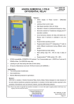
Liquid Crystal Display
A 2 line, 16 character backlit liquid crystal display (LCD) is used to present settings, instruments and fault data in
a textual format. The display backlighting is turned off to conserve power if no pushbuttons are pressed for 5
minutes. After an hour, the whole display is de-activated, except in the case of the instruments, which remain
visible permanently.
‘Protection Healthy’ LED
This green LED indicates that DC volts have been applied to the Argus and that the relay is operating correctly. If
a permanent fault is detected by the internal watchdog, then this LED will continuously flash.
‘Starter’ LED
This self-resetting yellow LED indicates that any pole is measuring current above the IDMTL/DTL current setting.
‘Trip’ LED
This latching red LED indicates that a trip, as defined by customer setting, has occurred. Such a trip may have
been issued by any of the protection functions. The user will be given more detailed information concerning the
trip from the LCD screen.
After being energised the LED can be reset by pressing the TEST/RESET key, or by energising a status input
which has been programmed to reset latched relays and the trip LED.
‘CB Open’ LED
Argus 4 and Argus 6 only.
This green LED indicates that the circuit breaker is open.
‘CB Closed’ LED
Argus 4 and Argus 6 only.
This red LED indicates that the circuit breaker is closed.
Keypad
Five keys are provided to control the functions of the Argus by moving around the menu display. They are
labelled: , , ENTER, CANCEL and . The key is also labelled TEST/RESET.
Only two push buttons are accessible when the front cover is in place. These are the and buttons which
allow the user to view all displays, including settings, but not to change setting values.
1.2.4 Current and Voltage Inputs
Current Inputs
Two types of current input are incorporated within the Argus range. One type of input is used for phase fault and
earth fault protection, while the other is used for sensitive earth fault and restricted earth fault protection. The
current inputs can be configured for operation with either 1A or 5A transformers. The appropriate connections are
required on the terminal blocks and the CT rating must be set as required.
Voltage Inputs
Argus 2 and Argus 6 only - Voltage inputs are used for setting the direction of the overcurrent elements and up to
4 voltage inputs are provided.
In most models voltage inputs for the phase voltages must be connected phase-phase, while a separate opendelta VT must provide the neutral voltage. In some models, however, the option is given to connect 3 voltage
inputs in a star configuration.
Each voltage input is capable of being connected to VTs with a nominal 63.5V or 110V secondary voltage.
1.2.5 Status Inputs and Output Relays
Four configurations of digital I/O are available:
x
x
x
1 status input, 7 output relays (3 changeover, 4 normally open)
3 status inputs, 5 output relays (3 changeover, 2 normally open)
5 status inputs, 11 output relays (3 changeover, 8 normally open)
©2010 Siemens Protection Devices Limited
P20006 Page 5 of 37