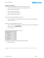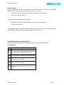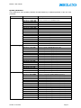
1
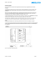
Alarm Monitor - M4200 User manual Revision: 07.02.2008 SELCO A/S ∙ P.O. Box 113 ∙ Betonvej 10 ∙ DK-4000 Roskilde ∙ Phone: +45 7026 1122 ∙ Fax: +45 7026 2522 ∙ www.selco.com M4200 - User manual Table of contents TABLE OF CONTENTS ...................................................................................................................................................... 1 INTRODUCTORY NOTES ................................................................................................................................................. 3 LAYOUT ................................................................................................................................................................................. 3 FACILITIES ON THE FRONT .................................................................................................................................................... 3 FACILITIES ON THE REAR ...................................................................................................................................................... 3 FUNCTION ............................................................................................................................................................................. 4 FUNCTION DIAGRAM ............................................................................................................................................................. 4 INSTALLATION INSTRUCTIONS .................................................................................................................................. 5 SINGLE UNIT .......................................................................................................................................................................... 5 MULTIPLE UNITS ................................................................................................................................................................... 6 Synchronisation................................................................................................................................................................ 6 RELAY OUTPUTS.................................................................................................................................................................... 7 Normally de-energized..................................................................................................................................................... 7 Normally energized .......................................................................................................................................................... 8 Load capacity ................................................................................................................................................................... 9 OPEN COLLECTOR OUTPUTS ............................................................................................................................................... 10 Normally de-energized................................................................................................................................................... 10 Normally energized ........................................................................................................................................................ 10 Load capacity ................................................................................................................................................................. 10 NC INPUT CONTACTS .......................................................................................................................................................... 11 Example .......................................................................................................................................................................... 11 CABLE MONITORING ........................................................................................................................................................... 12 Example .......................................................................................................................................................................... 12 Input reference ............................................................................................................................................................... 12 Normally open inputs ..................................................................................................................................................... 12 Normally closed inputs .................................................................................................................................................. 12 Inputs in general............................................................................................................................................................. 12 INPUT REFERENCE ............................................................................................................................................................... 13 Example .......................................................................................................................................................................... 13 PROGRAMMING BY SWITCHES................................................................................................................................. 14 ROTARY SWITCH - OPERATIONAL PRINCIPLE ..................................................................................................................... 14 DIP SWITCHES - OPERATIONAL PRINCIPLE .......................................................................................................................... 15 Factory default - dip switches........................................................................................................................................ 15 Factory default – all settings ......................................................................................................................................... 15 Set button ........................................................................................................................................................................ 16 Acknowledge LED.......................................................................................................................................................... 16 DIP SWITCH - PROGRAMMING ............................................................................................................................................. 17 Input settings .................................................................................................................................................................. 17 General settings.............................................................................................................................................................. 19 WINDOWS® SOFTWARE ................................................................................................................................................ 21 LOCATE HYPERTERMINAL ON THE PC .............................................................................................................................. 21 INSTALLING HYPERTERMINAL ........................................................................................................................................... 22 WIRING ................................................................................................................................................................................ 22 CREATE A NEW CONNECTION ............................................................................................................................................. 23 ASCI settings .................................................................................................................................................................. 24 SAVE CONNECTION ............................................................................................................................................................. 25 INTRODUCTION TO MICROSOFT® HYPERTERMINAL ......................................................................................................... 25 Icon explanation............................................................................................................................................................. 25 Revision: 07.02.2008 Page 1 M4200 - User manual PROGRAMMING BY PC.................................................................................................................................................. 26 READ CONFIG ...................................................................................................................................................................... 26 SYSTEM PARAMETERS......................................................................................................................................................... 27 Channel functions .......................................................................................................................................................... 27 Input contact type ........................................................................................................................................................... 27 Input reference ............................................................................................................................................................... 27 Cable monitoring ........................................................................................................................................................... 28 Input delay ...................................................................................................................................................................... 28 LED colour ..................................................................................................................................................................... 28 Block function 1.............................................................................................................................................................. 29 Block function 2.............................................................................................................................................................. 29 Alarm 1 (output relay 1) ................................................................................................................................................ 29 Alarm 2 (output relay 2) ................................................................................................................................................ 30 Siren (relay).................................................................................................................................................................... 30 Output 1 - 4..................................................................................................................................................................... 30 Output relay 1 (contact)*............................................................................................................................................... 31 Output relay 2 (contact)*............................................................................................................................................... 31 Siren relay (contact)*..................................................................................................................................................... 31 Output 1 – 4 (contact)* .................................................................................................................................................. 31 Output relay 1 (signal)*................................................................................................................................................. 31 Output relay 2 (signal)*................................................................................................................................................. 31 Siren relay (signal)*....................................................................................................................................................... 31 Unblock delays ............................................................................................................................................................... 32 Reset functions................................................................................................................................................................ 32 Factory default ............................................................................................................................................................... 32 SAVE SETTINGS IN A TEXT FILE ........................................................................................................................................... 33 LOAD SETTINGS FROM A TEXT FILE .................................................................................................................................... 34 Revision: 07.02.2008 Page 2 M4200 - User manual Introductory notes This manual describes installation and operating instructions together with dip switch configuration of the Alarm Monitor M4200. This manual also includes information about how to configure the product, using the included RS232 cable ® ® and a Windows PC running Microsoft HyperTerminal. Layout Below is a description of the facilities on the front and the rear of the unit. Facilities on the front 8 LEDs, one for each input terminal. By programming it is possible to change the colour individually for each LED, into red, green or yellow. Green LED. Active when power is on. When test button is pushed, all LEDs show steady light. Hold down the button and test status will change from red into green and into yellow. When reset button is pushed, all relay outputs go off and LED status change from flashing to steady mode Keep down the button and dimming of all LEDs can be done in 8 consecutive levels. Facilities on the rear Output terminals. 4 open collector outputs for remote control of external lamps or relays. Input terminals. Used for connection of potential free contacts. Both NO and NC contacts are supported. Sync. Used for synchronization of flashing LEDs on multiple M4200 units. Power. Terminal 24 is positive reference. Terminal 26 is negative reference. Terminal 25 is not in use. +REF and GND. Reference to inputs. +REF is the same as positive power reference. GND is galvanically separated from the negative power reference. Output relays. Alarm 1 is default activated when inputs are active. It is possible to set up activation mode for both alarm 1 and 2. Reset, test and block functionality for remote activation. GND is common reference. Siren relay. Default activated when inputs are active. It is possible to set up activation mode for the siren relay. RS232 interface. Used for connection with PC. 10 channel rotary switch. Used for switch configuration of the unit: 0: Operational mode 1 - 8: Set input 1 - 8 9: Set general functions Set button. Used for accept of rotary and dip switch settings. Acknowledge LED. Indicates that programming by set button is accepted. Revision: 07.02.2008 8 dip switches. Used for configuration of the unit. Named in documentation as 1-1 to 1-8. 8 dip switches. Used for configuration of the unit. Named in documentation as 2-1 to 2-8. Page 3 M4200 - User manual Function The Alarm Monitor M4200 provides the possibility of monitoring 8 individual processes. All inputs will accept any combination of NO or NC contacts. It is possible to programme each input, e.g. to activate the siren relay, the two alarm relays or the four open collector outputs. The delays for the inputs can be selected between 25 milliseconds and 60 seconds. With the default configuration on M4200, the alarm scenario will unfold as shown in Figure 1. Figure 1. Function diagram, default scenario. Function diagram When alarm input is activated, the LED goes flashing, alarm relay 1 and the siren relay goes ON. When reset button is activated, the LED goes steady and the siren goes OFF. When alarm input is de-activated, LED goes OFF, together with alarm 1. Revision: 07.02.2008 Page 4 M4200 - User manual Installation instructions This section contains information about how to install the alarm monitor. Single unit Figure 2 shows the default connection of the input and output terminals on the alarm monitor. Input terminals 1 - 8 are connected to +REF OUT (positive supply) via potential free contacts. Reset, test and block terminals are connected to GND via potential free contacts. Lamps are connected to the outputs; the lamps are supplied from same source as the unit. Terminal 26 is connected to ÷ (negative supply). Figure 2. Wiring example, single unit (default connection). Revision: 07.02.2008 Page 5 M4200 - User manual Multiple units Figure 3 shows the default connection of the input and output terminals on two M4200 units. Input terminals 1 - 8 are connected to +REF OUT (positive supply) on one of the units via potential free contacts. Test terminals are connected to GND on both units via potential free contacts (test and block terminals can be connected by the same method). Lamps are connected to the outputs; the lamps are supplied from same source as the units. Terminal 26 is connected to ÷ (negative supply). Figure 3. Wiring example, multiple units with external reset (default connection). Synchronisation If multiple units are positioned side by side it can be desirable that all LEDs, on all the units are flashing with the same speed rate. If all Sync terminals (23) on all the multiple units are connected with each other, all LEDs will operate with the same speed rate. No further configuration is needed. The Sync functionality has no other importance than providing visual continuity. Revision: 07.02.2008 Page 6 M4200 - User manual Relay outputs The alarm monitor has 3 output relays; all of them can be activated by any of the 8 alarm inputs. The relays can work as de-energized or energized, when the power is on the alarm monitor. The alarm monitor is delivered with all output relays operating in normally de-energized mode. This section contains information about the 2 principles and how and when to use them. This section only contains information about the relay outputs (terminal 27 - 35). The examples in this section are based on the siren relay, but all of the 3 output relays can be used individually with the same functionality. Normally de-energized Figure 4 shows the default connection of the output terminals on the alarm monitor. The alarm monitor is delivered with all output relays operating in normally de-energized mode. This means that the relay stays in the same position, whether the power is on or off. When an incoming alarm activates the relay, the position will change from terminal 33 to 35 (siren relay). The output relay is supplied from same source as the unit. The siren is connected to the output relay. Terminal 26 and the siren are connected to ÷ (negative supply). NOTE: Regarding load capacity for the output relays, please refer to the section Load capacity on page 9 in this manual. Figure 4. Wiring example, normally de- energized relay (default connection). Revision: 07.02.2008 Page 7 M4200 - User manual Normally energized Figure 5 shows the connection of the output terminals when the relay is programmed to be normally energized. It is possible to programme each of the output relays to operate individually as normally energized. This means that the relay changes position from terminal 33 to terminal 35 (siren relay) when the power is switched on. When an incoming alarm activates the relay, the position will change from terminal 35 to 33 (siren relay). The same scenario will appear if the supply voltage disappears from the alarm monitor. This is a big advantage when alarm is needed, if breakdown of the alarm system occurs. If supply voltage disappears from the alarm monitor and alarm is needed, it is very important to use another supply unit for the output relays, than used for the supply voltage of the alarm monitor. The output relay is supplied from another source than the alarm monitor. The siren is connected to the output relay. The siren is connected to another ÷ (negative supply) than that of the alarm monitor. NOTE: Regarding load capacity for the output relays, please refer to the section Load capacity on page 9. To use any of the three output relays as normally energized, programming is needed. For further information about programming please refer to the section Programming by switches on page 14 or Programming by PC on page 26. Figure 5. Wiring example, normally energized relay. Revision: 07.02.2008 Page 8 M4200 - User manual Load capacity The output relays are able to manage any kind of resistive load. The load capacity depends on whether AC or DC voltage is connected to the relay. Below is listed the maximum load capacity for AC and DC voltage respectively: Max. AC load: 250VAC / 4A Max. DC load: Readings of DC load capacity curve above: Revision: 07.02.2008 VDC 10 12 24 48 110 300 Ampere 4 4 4 2 0,5 0,1 Page 9 M4200 - User manual Open collector outputs The alarm monitor has 4 open collector outputs; all of them can be activated by any of the 8 alarm inputs. These outputs are able to work as energized or de- energized, similar to the output relays. This section contains information about the 2 principles and how to use them. Figure 6 shows the connection diagram of the output terminals (terminal 19 - 22) on the alarm monitor. Figure 6. Wiring example, open collector outputs. Normally de-energized The alarm monitor is delivered with all open collector outputs operating as normally de-energized. This means that the output has no reference whether power is on or off. When an incoming alarm activates the output, status is changing to negative (÷) reference. Normally energized It is possible to programme each of the open collector outputs to operate individually as normally energized. This means that the output changes to negative (÷) reference when the power is switched on. When an incoming alarm activates the output, status is changing and the negative (÷) reference disappears. Load capacity Maximum load capacity for the open collector outputs is 60VDC / 700mA. Revision: 07.02.2008 Page 10 M4200 - User manual NC input contacts IMPORTANT: It is only recommended to use the example below if the alarm monitor is still in factory default mode. If there is any possibility that the alarm monitor has been programmed previously, please refer to the section Factory default - dip switches on page 15. Example Input 1 - 8 accept any combination of NO or NC contacts. Default configuration only supports NO contacts. If NC contacts are used, please follow the example below regarding input 1, terminal 1: 1. Set rotary switch in position 1 (acknowledge LED change into red colour). 2. Set dip switch 1-1 to On (NC contact). 3. Press Set button until Acknowledge LED shortly turns into green light. 4. Release Set button. Now it is possible to connect input 1 as shown in Figure 7: Figure 7. Wiring example, NC input If NC contacts are needed on any other input channels, please select the input number on the rotary switch and follow step 3 and 4 above. Revision: 07.02.2008 Page 11 M4200 - User manual Cable monitoring Cable monitoring provides extra security to the alarm system. Cable faults are indicated with short flashing pulses on the corresponding alarm channels. Cable fault indications will be overridden by activation of input alarms and indicated with normal alarm flash or steady light indication. IMPORTANT: It is only recommended to use the example below if the alarm monitor is still in factory default mode. If there is any possibility that the alarm monitor has been programmed previously, please refer to the section Factory default - dip switches on page 15. Example The example below refer to input 1, terminal 1: 1. Set rotary switch in position 1 (acknowledge LED change into red colour). 2. Set dip switch 1-3 to On (Cable monitoring). 3. Press Set button until Acknowledge LED shortly turns into green light. 4. Release Set button. Now it is possible to connect input 1 as shown in Figure 8 and Figure 8. Wiring example, cable monitoring on input 1 If cable monitoring is needed on any other input channel, please select the input number on the rotary switch and follow step 3 and 4 above. Notice that two measuring resistors (1 in series and 1 in parallel) are needed for each of the inputs operating with cable monitoring. It is very important that both resistors are mounted close to the input contact. Input reference In the example above + REF OUT (9) is used as input reference. It is possible to use both + Ref (9) and GND Ref (10) with cable monitoring without further configuration. Normally open inputs The resistor in parallel is monitoring cable break. The resistor in serial is monitoring short circuit. Normally closed inputs The resistor in parallel is monitoring short circuit. The resistor in serial is monitoring cable break. Inputs in general However the input is operating as, normally open or normally closed, same size of resistors is used. Revision: 07.02.2008 Page 12 M4200 - User manual Input reference IMPORTANT: It is only recommended to use the programming example below if the alarm monitor is still in factory default mode. If there is any possibility that the alarm monitor has been programmed before, please refer to the section Factory default - dip switches on page 15. Example It is possible to set up input 1-8 individually to positive or negative reference. Default configuration is positive reference via the terminal +REF OUT. If negative reference is needed, please follow the example below regarding input 1, terminal 1: 1. Set rotary switch in position 1 (acknowledge LED change into red colour). 2. Set dip switch 1-2 to Off (GND reference). 3. Press Set button until Acknowledge LED shortly turns into green light. 4. Release Set button. Now it is possible to connect input 1 as shown in Figure 9: Figure 9. Wiring example, GND If GND reference is needed on any other input channel, please select the input number on the rotary switch and follow step 3 and 4 above. Revision: 07.02.2008 Page 13 M4200 - User manual Programming by switches There are two ways of programming the alarm monitor; by dip switches on the rear of the unit or by any ® standard ANSI compatible terminal application e.g. Microsoft HyperTerminal (which is supplied with the ® Windows operating system) or any other ANSI terminal. When using a standard ANSI compatible terminal application, the configuration is done through a PC, via the special RS232 cable, which is delivered with the M4200 unit. This section only contains information about programming by dip switches. Switches All switches needed for programming are located on the rear of the alarm monitor. There is 1 rotary switch with 10 channels for mode selection and 2 rows of dip switches with each 8 dip switches for choosing different programming facilities. Below is a description of the functions, both on the rotary switch and the dip switches. Rotary switch - operational principle Below is an explanation of the different modes on the rotary switch. Figure 10 illustrates the different modes schematically. Position “0” is operational mode. This mode is default selected and means that the alarm monitor is running in alarm mode. Position 1 – 8 is programming mode for each of the input channels. Programming functions into channel 1, set the rotary switch in position 1 etc. Position 9 is programming mode for general functions, such as block, delay and reset functions. Position 0 1 2 3 4 5 6 7 8 9 Mode Operational (alarm) Set input 1 Set input 2 Set input 3 Set input 4 Set input 5 Set input 6 Set input 7 Set input 8 Set general functions Figure 10. Modes on rotary switch. Revision: 07.02.2008 Page 14 M4200 - User manual Dip switches - operational principle 8 dip switches (1. row). Named in documentation as 1.1 to 1.8. 8 dip switches (2. row). Named in documentation as 2.1 to 2.8. There are 16 dip switches spread on 2 rows with 8 in each row. Each dip switch has 2 positions; ON and OFF (2 functions per dip switch). The functions of each dip switch depend on the position of the rotary. This means that 2 × 16 (on/off) different settings are available on each of the 9 positions on the rotary switch (no programming facilities are available when the rotary switch is in position 0, operational mode). When the rotary switch is in position 1 – 8, each dip switch has the same functions because the same functions are needed on each input channel. Factory default - dip switches Figure 11 shows how all the dip switches are set, when the alarm monitor leaves the SELCO factory. Before starting any programming session on the alarm monitor, it is recommended to set all dip switches as shown in Figure 11. The reason is that when saving is done by the set button, all settings will be saved even though only a few dip switch positions have been changed. Top row of dip switches (1) ON OFF X X X 1.1 1.2 X X X X X 1.3 1.4 1.5 1.6 1.7 1.8 X X X 2.6 2.7 2.8 Bottom row of dip switches (2) ON OFF X X X 2.1 2.2 X X 2.3 2.4 2.5 Figure 11. Dip switch settings (factory default). Factory default – all settings It is possible to return all settings on the alarm monitor into factory default by 1 operating cycle: 1. 2. 3. 4. 5. Set the rotary switch in position 0. Press the button “Set” (the colour of the “Ack” LED changes into red light). Hold “Set” button down in 5 seconds. The colour of the “Ack” LED changes into green light. Release the “Set” button. Now all settings are returned to factory default. It is still necessary to set up all dip switch contacts manually (please refer to the previous section in this manual). Revision: 07.02.2008 Page 15 M4200 - User manual Set button The set button is positioned on the rear of the alarm monitor, below the dip switches. This push button is used for accept of rotary and dip switch settings. Set button is related to the rotary switch, which means that all dip switch settings made, in the selected position of the rotary switch, will be saved when the set button is pushed. IMPORTANT It is very important to check the position of all 16 dip switches before set button is pushed. Acknowledge LED Acknowledge LED is positioned on the rear of the alarm monitor, beside the save button. When the rotary switch is in programming mode (Position 1 - 9) the LED gives a constant red light. When set button is pushed and held down, the LED will flash 2 times and change into green light until set button is released. Green light indicates that saving the settings done by set button is accepted. Revision: 07.02.2008 Page 16 M4200 - User manual Dip switch - programming This section lists all possible settings that can be done by the switches on the rear of the alarm monitor. Before starting the programming session please read the previous section Dip switches - operational principle on page 15. Input settings Before programming the input settings please select the position number on the rotary switch (position 1 - 8). In the table below the default settings are marked with bold type. Switch row 1 Function Input type Input reference Cable monitoring Input Delay LED Colour Revision: 07.02.2008 Switch setting SW1.1 OFF ON SW1.2 OFF ON SW1.3 OFF ON SW1.4 OFF OFF OFF OFF ON ON ON ON SW1.7 OFF OFF ON ON Switch setting Switch setting Description Normally Open Normally Closed GND +VREF OUT Inactive Active SW1.5 OFF OFF ON ON OFF OFF ON ON SW1.8 OFF ON OFF ON SW1.6 OFF ON OFF ON OFF ON OFF ON 25 ms 500 ms 1s 2s 5s 10 s 30 s 60 s No light Red Green Yellow Page 17 M4200 - User manual Switch row 2 Function Block1 Block2 Alarm1 Alarm2 Siren Out1 Out2 Out3 Revision: 07.02.2008 Switch setting SW2.1 OFF ON SW2.2 OFF ON SW2.3 OFF ON SW2.4 OFF ON SW2.5 OFF ON SW2.6 OFF ON SW2.7 OFF ON SW2.8 OFF ON Description No effect Block No effect Block No effect Activate No effect Activate No effect Activate No effect Activate No effect Activate No effect Activate Page 18 M4200 - User manual General settings Before programming the general settings please select the position number on the rotary switch (position 9). In the table below the default settings are marked with bold type. Switch row 1 Function Alarm Relay 1 Alarm Relay 2 Siren Relay Open Collector 1 Open Collector 2 Open Collector 3 Open Collector 4 Spare Revision: 07.02.2008 Switch setting SW 1.1 OFF ON SW 1.2 OFF ON SW 1.3 OFF ON SW 1.4 OFF ON SW 1.5 OFF ON SW 1.6 OFF ON SW 1.7 OFF ON SW 1.8 OFF ON Description Normally De-energized Nomally Energized Normally De-energized Nomally Energized Normally De-energized Nomally Energized Normally De-energized Normally low Normally De-energized Normally low Normally De-energized Normally low Normally De-energized Normally low No effect No effect Page 19 M4200 - User manual Switch row 2 Function UnBlock Delay Gr1 UnBlock Delay Gr2 Reset button Alarm relay 1* Alarm relay 2* Siren relay* Switch setting SW 2.1 OFF OFF ON ON SW 2.3 OFF OFF ON ON SW 2.5 OFF ON SW 2.6 OFF ON SW 2.7 OFF ON SW 2.8 OFF ON Switch setting SW 2.2 OFF ON OFF ON SW 2.4 OFF ON OFF ON Description 1 Sec 5 Sec 10 Sec 15 Sec 1 Sec 5 Sec 10 Sec 15 Sec One push: Reset all. Two push: First siren, second LEDs Steady (no pulse) New alarm: 2 second pulse Steady (no pulse) New alarm: 2 second pulse Steady (no pulse) New alarm: 2 second pulse (Relays) * These functions are available from firmware version; January 2008. Revision: 07.02.2008 Page 20 M4200 - User manual Windows® software There are two ways of programming the alarm monitor; by dip switches on the rear of the unit or by any ® standard ANSI compatible terminal application e.g. Microsoft HyperTerminal (which is supplied with the ® Windows operating system) or any other ANSI terminal. ® ® Windows NT, 2000, XP and Vista will normally install HyperTerminal by default. Windows 95, 98 and ME will in contrast not install HyperTerminal by default. ® This section describes how to locate and eventually install Microsoft HyperTerminal on a PC. All information regarding wiring and communication between a PC and the alarm monitor is also available in this section. Locate HyperTerminal on the PC ® It is important to make sure that an ANSI terminal application is installed on the PC. To find out if Microsoft HyperTerminal is already installed: ® 1. Click on the Start button (in the lower left corner of the Windows screen). ) 2. Click on the menu item All programs* . 3. Click on the menu item Accessories. 4. Click on the menu item Communication. 5. Check if there is a menu item named: HyperTerminal. ® If you have already installed Microsoft HyperTerminal, please continue in the section Wiring on page 22. *) On Windows® XP the button is named All programs. If the operating system is older than Windows® XP, the button is only named Programs. Revision: 07.02.2008 Page 21 M4200 - User manual Installing HyperTerminal ® This section describes the procedure for installing HyperTerminal, which is supplied on the Windows 9x CD-ROM. Please note that the installing procedure for HyperTerminal might be a little different depending on which ® version of Windows you have installed. It should, however, be possible to configure the system using this procedure: ® 1. Click on the Start button (in the lower left corner of the Windows screen). 2. Click on the menu item Control panel. When the Control Panel appears on the screen: 3. Double-click on the Add/Remove Programs icon. When the Add/Remove Programs Properties dialogue appears on the screen: 4. Click on the tab Windows Setup. 5. Click on Communications components. 6. Click on the button Details. 7. Enable the check box just left of the HyperTerminal application. 8. Click on the button OK. Windows will now ask for the installation CD-ROM. After inserting the CD-ROM, Windows will install the files needed for the HyperTerminal application. Wiring HyperTerminal is now fully installed and it is time for connecting the alarm monitor with the PC: 1. Plug one end of the supplied RS232 cable into the grey RJ plug (located in the lower left corner on the rear of the alarm monitor). 2. The other end of the cable (with the DB9 plug) connects to a PC COM port (COM1 is used in this manual). Revision: 07.02.2008 Page 22 M4200 - User manual Create a new connection HyperTerminal is now fully installed and it is time for creating a new connection: ® 1. Click on the Start button (in the lower left corner of the Windows screen). ) 2. Click on the menu item All programs* . 3. Click on the menu item Accessories. 4. Click on the menu item Communication. 5. Click on the menu item HyperTerminal. When the New connection dialogue appears on the screen: 6. Type in Direct COM1 (assuming that COM1 is used for the connection) in the input field Name. 7. Click on the button OK. When the Connect to dialogue appears on the screen: 8. Click on the drop down menu, opposite the input field Connect to, and choose which COM port you want to connect to, e.g. . 9. Click on the button OK. When the Port Settings dialogue appears on the screen: Please make sure that the dialog is filled out exactly like the picture above! 10. Click on the button OK. *) On Windows® XP the button is named All programs. If the operating system is older than Windows® XP, the button is only named Programs. Revision: 07.02.2008 Page 23 M4200 - User manual ASCI settings The HyperTerminal dialogue appears on the screen. ® To make sure that communication between Microsoft HyperTerminal and the alarm monitor will work properly, some settings regarding transmission of data are needed: 1. Click on the menu Files. 2. Click on the menu item Properties. When the properties dialog appears on the screen: 3. Click on the tab Settings. 4. Click on the button ASCII-settings. When the ASCII Setup dialogue appears on the screen: Please make sure that the dialog is filled out exactly like the picture above! 5. Click on the button OK. The alarm monitor is now connected to the PC through RS232. The screen dump below shows the welcome message, transmitted by the M4200 alarm monitor, which indicates that it is ready for configuration. Revision: 07.02.2008 Page 24 M4200 - User manual Save connection ® In order to avoid the starting and configuration procedure every time you start up the Microsoft HyperTerminal in the future, it is practical to save the setup. To save setup: 1. Click on the menu File (in the upper left corner of the HyperTerminal dialogue). 2. Click on the menu item Save as... The Save as… dialogue will appear on the screen: 3. Note that the name Direct COM1 is already typed into the input field Filename. 4. Click on the button Save. The configuration has been saved as a HyperTerminal shortcut icon. This icon (named Direct COM1) can be accessed directly through the start menu (same location as HyperTerminal). Introduction to Microsoft® HyperTerminal ® Below you will find an explanation for the frequently used icons in Microsoft HyperTerminal. Icon explanation Icon Description Use this icon if you need to create a new connection e.g. if you need to communicate through another COM port than your default connection does Use this icon if you need to open a new connection e.g. the connection you have saved as Direct COM1 Use this icon if you need to connect to the unit related to the pc e.g. M4200 Use this icon if you need to disconnect to the unit related to the pc e.g. M4200 Use this icon if you need to correct some of the properties for the active connection e.g. Direct COM1 Revision: 07.02.2008 Page 25 M4200 - User manual Programming by PC There are two ways of programming the alarm monitor; by dip switches on the rear of the unit or by any ® standard ANSI compatible terminal application e.g. Microsoft HyperTerminal (which is supplied with the ® Windows operating system) or any other ANSI terminal. When using a standard ANSI compatible terminal application, the configuration is done through a PC, via the special RS232 cable which is delivered with the alarm monitor. The 16 dip switches have a limited number of combinations and provide only restricted combinations for e.g. channels and delays. Otherwise the RS232 based configuration is unrestricted. In this section, all necessary information regarding programming of the alarm monitor from a PC is available. Read config It is possible to read out the present configuration of the alarm monitor, by writing a single command into the terminal window. Make sure that the RS232 port on the alarm monitor is connected to the PC serial port (COM1), and the power is turned on. ® To start up the programming window (Microsoft HyperTerminal): ® 1. Click on the Start button (in the lower left corner of the Windows screen). ) 2. Click on the menu item All programs* . 3. Click on the menu item Accessories. 4. Click on the menu item Communication. 5. Click on the menu folder HyperTerminal. 6. Click on the menu item Direct COM1. The HyperTerminal dialogue will appear on the screen: 7. Type the text read config in the terminal window. 8. Press the Enter key on the keyboard. All parameters are now listed in the terminal window. All parameters can be changed or activated according to the descriptions on every single parameter, which you are able to read about on the following pages. Please type the complete command and press ENTER. The parameter is automatically saved into the unit. *) On Windows® XP the button is named All programs. If the operating system is older than Windows® XP, the button is only named Programs. Revision: 07.02.2008 Page 26 M4200 - User manual System parameters In the table below every possible parameter is listed followed by a detailed explanation of the use of the parameter: Parameter Command Description WRITE IN1 FUNC ALR WRITE IN2 FUNC ALR WRITE IN3 FUNC ALR WRITE IN4 FUNC ALR WRITE IN5 FUNC ALR WRITE IN6 FUNC ALR WRITE IN7 FUNC ALR WRITE IN8 FUNC ALR WRITE IN1 FUNC IND WRITE IN2 FUNC IND WRITE IN3 FUNC IND WRITE IN4 FUNC IND WRITE IN5 FUNC IND WRITE IN6 FUNC IND WRITE IN7 FUNC IND WRITE IN8 FUNC IND Channel 1 will function as normal alarm channel WRITE IN1 TYPE NO WRITE IN2 TYPE NO WRITE IN3 TYPE NO WRITE IN4 TYPE NO WRITE IN5 TYPE NO WRITE IN6 TYPE NO WRITE IN7 TYPE NO WRITE IN8 TYPE NO WRITE IN1 TYPE NC WRITE IN2 TYPE NC WRITE IN3 TYPE NC WRITE IN4 TYPE NC WRITE IN5 TYPE NC WRITE IN6 TYPE NC WRITE IN7 TYPE NC WRITE IN8 TYPE NC Channel 1 supports a normally open input contact WRITE IN1 REF VREF WRITE IN2 REF VREF WRITE IN3 REF VREF WRITE IN4 REF VREF WRITE IN5 REF VREF WRITE IN6 REF VREF WRITE IN7 REF VREF WRITE IN8 REF VREF WRITE IN1 REF GND WRITE IN2 REF GND WRITE IN3 REF GND WRITE IN4 REF GND WRITE IN5 REF GND WRITE IN6 REF GND WRITE IN7 REF GND WRITE IN8 REF GND Channel 1 is configured for positive reference (terminal 9) Channel functions Channel 2 will function as normal alarm channel Channel 3 will function as normal alarm channel Channel 4 will function as normal alarm channel Channel 5 will function as normal alarm channel Channel 6 will function as normal alarm channel Channel 7 will function as normal alarm channel Channel 8 will function as normal alarm channel Channel 1 will function only as indicator channel Channel 2 will function only as indicator channel Channel 3 will function only as indicator channel Channel 4 will function only as indicator channel Channel 5 will function only as indicator channel Channel 6 will function only as indicator channel Channel 7 will function only as indicator channel Channel 8 will function only as indicator channel Input contact type Channel 2 supports a normally open input contact Channel 3 supports a normally open input contact Channel 4 supports a normally open input contact Channel 5 supports a normally open input contact Channel 6 supports a normally open input contact Channel 7 supports a normally open input contact Channel 8 supports a normally open input contact Channel 1 supports a normally closed input contact Channel 2 supports a normally closed input contact Channel 3 supports a normally closed input contact Channel 4 supports a normally closed input contact Channel 5 supports a normally closed input contact Channel 6 supports a normally closed input contact Channel 7 supports a normally closed input contact Channel 8 supports a normally closed input contact Input reference Revision: 07.02.2008 Channel 2 is configured for positive reference (terminal 9) Channel 3 is configured for positive reference (terminal 9) Channel 4 is configured for positive reference (terminal 9) Channel 5 is configured for positive reference (terminal 9) Channel 6 is configured for positive reference (terminal 9) Channel 7 is configured for positive reference (terminal 9) Channel 8 is configured for positive reference (terminal 9) Channel 1 is configured for negative reference (terminal 10) Channel 2 is configured for negative reference (terminal 10) Channel 3 is configured for negative reference (terminal 10) Channel 4 is configured for negative reference (terminal 10) Channel 5 is configured for negative reference (terminal 10) Channel 6 is configured for negative reference (terminal 10) Channel 7 is configured for negative reference (terminal 10) Channel 8 is configured for negative reference (terminal 10) Page 27 M4200 - User manual Parameter Command Description WRITE IN1 CABLE OFF WRITE IN2 CABLE OFF WRITE IN3 CABLE OFF WRITE IN4 CABLE OFF WRITE IN5 CABLE OFF WRITE IN6 CABLE OFF WRITE IN7 CABLE OFF WRITE IN8 CABLE OFF WRITE IN1 CABLE ON WRITE IN2 CABLE ON WRITE IN3 CABLE ON WRITE IN4 CABLE ON WRITE IN5 CABLE ON WRITE IN6 CABLE ON WRITE IN7 CABLE ON WRITE IN8 CABLE ON There is no monitoring of cable faults on Channel 1 WRITE IN1 DELAY 25MS WRITE IN2 DELAY 25MS WRITE IN3 DELAY 25MS WRITE IN4 DELAY 25MS WRITE IN5 DELAY 25MS WRITE IN6 DELAY 25MS WRITE IN7 DELAY 25MS WRITE IN8 DELAY 25MS WRITE IN1 DELAY 1S WRITE IN2 DELAY 1S WRITE IN3 DELAY 1S WRITE IN4 DELAY 1S WRITE IN5 DELAY 1S WRITE IN6 DELAY 1S WRITE IN7 DELAY 1S WRITE IN8 DELAY 1S Channel 1 has a delay of 25ms. from input to respond Cable monitoring There is no monitoring of cable faults on Channel 2 There is no monitoring of cable faults on Channel 3 There is no monitoring of cable faults on Channel 4 There is no monitoring of cable faults on Channel 5 There is no monitoring of cable faults on Channel 6 There is no monitoring of cable faults on Channel 7 There is no monitoring of cable faults on Channel 8 Channel 1 gives alarm at cable fracture or short-circuit on input cable Channel 2 gives alarm at cable fracture or short-circuit on input cable Channel 3 gives alarm at cable fracture or short-circuit on input cable Channel 4 gives alarm at cable fracture or short-circuit on input cable Channel 5 gives alarm at cable fracture or short-circuit on input cable Channel 6 gives alarm at cable fracture or short-circuit on input cable Channel 7 gives alarm at cable fracture or short-circuit on input cable Channel 8 gives alarm at cable fracture or short-circuit on input cable Input delay 25ms - 999ms. are accepted values 1s - 999s are accepted values Channel 2 has a delay of 25ms. from input to respond Channel 3 has a delay of 25ms. from input to respond Channel 4 has a delay of 25ms. from input to respond Channel 5 has a delay of 25ms. from input to respond Channel 6 has a delay of 25ms. from input to respond Channel 7 has a delay of 25ms. from input to respond Channel 8 has a delay of 25ms. from input to respond Channel 1 has a delay of 1sec. from input to respond Channel 2 has a delay of 1sec. from input to respond Channel 3 has a delay of 1sec. from input to respond Channel 4 has a delay of 1sec. from input to respond Channel 5 has a delay of 1sec. from input to respond Channel 6 has a delay of 1sec. from input to respond Channel 7 has a delay of 1sec. from input to respond Channel 8 has a delay of 1sec. from input to respond LED colour WRITE LED1 COLOR RED WRITE LED2 COLOR RED WRITE LED3 COLOR RED WRITE LED4 COLOR RED WRITE LED5 COLOR RED RED, GREEN and WRITE LED6 COLOR RED YELL are accepted WRITE LED7 COLOR RED WRITE LED8 COLOR RED values Red, green and Yellow is possible colours Revision: 07.02.2008 The colour of the LED of channel 1 gives a red light The colour of the LED of channel 2 gives a red light The colour of the LED of channel 3 gives a red light The colour of the LED of channel 4 gives a red light The colour of the LED of channel 5 gives a red light The colour of the LED of channel 6 gives a red light The colour of the LED of channel 7 gives a red light The colour of the LED of channel 8 gives a red light Page 28 M4200 - User manual Parameter Command Description WRITE ALM1 BLOCK1 OFF WRITE ALM2 BLOCK1 OFF WRITE ALM3 BLOCK1 OFF WRITE ALM4 BLOCK1 OFF WRITE ALM5 BLOCK1 OFF WRITE ALM6 BLOCK1 OFF WRITE ALM7 BLOCK1 OFF WRITE ALM8 BLOCK1 OFF WRITE ALM1 BLOCK1 ON WRITE ALM2 BLOCK1 ON WRITE ALM3 BLOCK1 ON WRITE ALM4 BLOCK1 ON WRITE ALM5 BLOCK1 ON WRITE ALM6 BLOCK1 ON WRITE ALM7 BLOCK1 ON WRITE ALM8 BLOCK1 ON Blocking alarm input 1 is not possible (by block function 1) WRITE ALM1 BLOCK2 OFF WRITE ALM2 BLOCK2 OFF WRITE ALM3 BLOCK2 OFF WRITE ALM4 BLOCK2 OFF WRITE ALM5 BLOCK2 OFF WRITE ALM6 BLOCK2 OFF WRITE ALM7 BLOCK2 OFF WRITE ALM8 BLOCK2 OFF WRITE ALM1 BLOCK2 ON WRITE ALM2 BLOCK2 ON WRITE ALM3 BLOCK2 ON WRITE ALM4 BLOCK2 ON WRITE ALM5 BLOCK2 ON WRITE ALM6 BLOCK2 ON WRITE ALM7 BLOCK2 ON WRITE ALM8 BLOCK2 ON Blocking alarm input 1 is not possible (by block function 2) WRITE ALM1 RELAY1 ON WRITE ALM2 RELAY1 ON WRITE ALM3 RELAY1 ON WRITE ALM4 RELAY1 ON WRITE ALM5 RELAY1 ON WRITE ALM6 RELAY1 ON WRITE ALM7 RELAY1 ON WRITE ALM8 RELAY1 ON WRITE ALM1 RELAY1 OFF WRITE ALM2 RELAY1 OFF WRITE ALM3 RELAY1 OFF WRITE ALM4 RELAY1 OFF WRITE ALM5 RELAY1 OFF WRITE ALM6 RELAY1 OFF WRITE ALM7 RELAY1 OFF WRITE ALM8 RELAY1 OFF Alarm 1 (output relay 1) is active when alarm on input 1 is ON Block function 1 Blocking alarm input 2 is not possible (by block function 1) Blocking alarm input 3 is not possible (by block function 1) Blocking alarm input 4 is not possible (by block function 1) Blocking alarm input 5 is not possible (by block function 1) Blocking alarm input 6 is not possible (by block function 1) Blocking alarm input 7 is not possible (by block function 1) Blocking alarm input 8 is not possible (by block function 1) Blocking alarm input 1 is possible via external button (terminal 13) Blocking alarm input 2 is possible via external button (terminal 13) Blocking alarm input 3 is possible via external button (terminal 13) Blocking alarm input 4 is possible via external button (terminal 13) Blocking alarm input 5 is possible via external button (terminal 13) Blocking alarm input 6 is possible via external button (terminal 13) Blocking alarm input 7 is possible via external button (terminal 13) Blocking alarm input 8 is possible via external button (terminal 13) Block function 2 Blocking alarm input 2 is not possible (by block function 2) Blocking alarm input 3 is not possible (by block function 2) Blocking alarm input 4 is not possible (by block function 2) Blocking alarm input 5 is not possible (by block function 2) Blocking alarm input 6 is not possible (by block function 2) Blocking alarm input 7 is not possible (by block function 2) Blocking alarm input 8 is not possible (by block function 2) Blocking alarm input 1 is possible via external button (terminal 14) Blocking alarm input 2 is possible via external button (terminal 14) Blocking alarm input 3 is possible via external button (terminal 14) Blocking alarm input 4 is possible via external button (terminal 14) Blocking alarm input 5 is possible via external button (terminal 14) Blocking alarm input 6 is possible via external button (terminal 14) Blocking alarm input 7 is possible via external button (terminal 14) Blocking alarm input 8 is possible via external button (terminal 14) Alarm 1 (output relay 1) Revision: 07.02.2008 Alarm 1 (output relay 1) is active when alarm on input 2 is ON Alarm 1 (output relay 1) is active when alarm on input 3 is ON Alarm 1 (output relay 1) is active when alarm on input 4 is ON Alarm 1 (output relay 1) is active when alarm on input 5 is ON Alarm 1 (output relay 1) is active when alarm on input 6 is ON Alarm 1 (output relay 1) is active when alarm on input 7 is ON Alarm 1 (output relay 1) is active when alarm on input 8 is ON Alarm 1 (output relay 1) is NOT active when alarm on input 1 is ON Alarm 1 (output relay 1) is NOT active when alarm on input 2 is ON Alarm 1 (output relay 1) is NOT active when alarm on input 3 is ON Alarm 1 (output relay 1) is NOT active when alarm on input 4 is ON Alarm 1 (output relay 1) is NOT active when alarm on input 5 is ON Alarm 1 (output relay 1) is NOT active when alarm on input 6 is ON Alarm 1 (output relay 1) is NOT active when alarm on input 7 is ON Alarm 1 (output relay 1) is NOT active when alarm on input 8 is ON Page 29 M4200 - User manual Parameter Command Description WRITE ALM1 RELAY2 OFF WRITE ALM2 RELAY2 OFF WRITE ALM3 RELAY2 OFF WRITE ALM4 RELAY2 OFF WRITE ALM5 RELAY2 OFF WRITE ALM6 RELAY2 OFF WRITE ALM7 RELAY2 OFF WRITE ALM8 RELAY2 OFF WRITE ALM1 RELAY2 ON WRITE ALM2 RELAY2 ON WRITE ALM3 RELAY2 ON WRITE ALM4 RELAY2 ON WRITE ALM5 RELAY2 ON WRITE ALM6 RELAY2 ON WRITE ALM7 RELAY2 ON WRITE ALM8 RELAY2 ON Alarm 2 (output relay 2) is NOT active when alarm on input 1 is ON WRITE ALM1 SIREN ON WRITE ALM2 SIREN ON WRITE ALM3 SIREN ON WRITE ALM4 SIREN ON WRITE ALM5 SIREN ON WRITE ALM6 SIREN ON WRITE ALM7 SIREN ON WRITE ALM8 SIREN ON WRITE ALM1 SIREN OFF WRITE ALM2 SIREN OFF WRITE ALM3 SIREN OFF WRITE ALM4 SIREN OFF WRITE ALM5 SIREN OFF WRITE ALM6 SIREN OFF WRITE ALM7 SIREN OFF WRITE ALM8 SIREN OFF Siren is active when alarm on input 1 is ON WRITE ALM1 OUTPUT1 OFF WRITE ALM2 OUTPUT1 OFF WRITE ALM3 OUTPUT1 OFF WRITE ALM4 OUTPUT1 OFF WRITE ALM5 OUTPUT1 OFF WRITE ALM6 OUTPUT1 OFF WRITE ALM7 OUTPUT1 OFF WRITE ALM8 OUTPUT1 OFF WRITE ALM1 OUTPUT1 ON WRITE ALM2 OUTPUT1 ON WRITE ALM3 OUTPUT1 ON WRITE ALM4 OUTPUT1 ON WRITE ALM5 OUTPUT1 ON WRITE ALM6 OUTPUT1 ON WRITE ALM7 OUTPUT1 ON WRITE ALM8 OUTPUT1 ON Open collector output 1 is NOT active when alarm on input 1 is ON Alarm 2 (output relay 2) Alarm 2 (output relay 2) is NOT active when alarm on input 2 is ON Alarm 2 (output relay 2) is NOT active when alarm on input 3 is ON Alarm 2 (output relay 2) is NOT active when alarm on input 4 is ON Alarm 2 (output relay 2) is NOT active when alarm on input 5 is ON Alarm 2 (output relay 2) is NOT active when alarm on input 6 is ON Alarm 2 (output relay 2) is NOT active when alarm on input 7 is ON Alarm 2 (output relay 2) is NOT active when alarm on input 8 is ON Alarm 2 (output relay 2) is active when alarm on input 1 is ON Alarm 2 (output relay 2) is active when alarm on input 2 is ON Alarm 2 (output relay 2) is active when alarm on input 3 is ON Alarm 2 (output relay 2) is active when alarm on input 4 is ON Alarm 2 (output relay 2) is active when alarm on input 5 is ON Alarm 2 (output relay 2) is active when alarm on input 6 is ON Alarm 2 (output relay 2) is active when alarm on input 7 is ON Alarm 2 (output relay 2) is active when alarm on input 8 is ON Siren (relay) Siren is active when alarm on input 2 is ON Siren is active when alarm on input 3 is ON Siren is active when alarm on input 4 is ON Siren is active when alarm on input 5 is ON Siren is active when alarm on input 6 is ON Siren is active when alarm on input 7 is ON Siren is active when alarm on input 8 is ON Siren is NOT active when alarm on input 1 is ON Siren is NOT active when alarm on input 2 is ON Siren is NOT active when alarm on input 3 is ON Siren is NOT active when alarm on input 4 is ON Siren is NOT active when alarm on input 5 is ON Siren is NOT active when alarm on input 6 is ON Siren is NOT active when alarm on input 7 is ON Siren is NOT active when alarm on input 8 is ON Output 1 - 4 It is possible to replace “OUTPUT1” with “OUTPUT2”, “OUTPUT3” or “OUTPUT4” Revision: 07.02.2008 Open collector output 1 is NOT active when alarm on input 2 is ON Open collector output 1 is NOT active when alarm on input 3 is ON Open collector output 1 is NOT active when alarm on input 4 is ON Open collector output 1 is NOT active when alarm on input 5 is ON Open collector output 1 is NOT active when alarm on input 6 is ON Open collector output 1 is NOT active when alarm on input 7 is ON Open collector output 1 is NOT active when alarm on input 8 is ON Open collector output 1 is active when alarm on input 1 is ON Open collector output 1 is active when alarm on input 2 is ON Open collector output 1 is active when alarm on input 3 is ON Open collector output 1 is active when alarm on input 4 is ON Open collector output 1 is active when alarm on input 5 is ON Open collector output 1 is active when alarm on input 6 is ON Open collector output 1 is active when alarm on input 7 is ON Open collector output 1 is active when alarm on input 8 is ON Page 30 M4200 - User manual Parameter Command Output relay 1 (contact)* WRITE IORELAYS RELAY1 CONTACT ND WRITE IORELAYS RELAY1 CONTACT NE Output relay 2 (contact)* WRITE IORELAYS RELAY2 CONTACT ND WRITE IORELAYS RELAY2 CONTACT NE Description Alarm 1 (output relay 1) operates as normally deenergized Alarm 1 (output relay 1) operates as normally energized Alarm 2 (output relay 2) operates as normally deenergized Alarm 2 (output relay 2) operates as normally energized Siren relay (contact)* WRITE IORELAYS SIREN CONTACT ND WRITE IORELAYS SIREN CONTACT NE Output 1 – 4 (contact)* WRITE IORELAYS OUTPUT1 ND WRITE IORELAYS OUTPUT1 NE WRITE IORELAYS OUTPUT2 ND WRITE IORELAYS OUTPUT2 NE WRITE IORELAYS OUTPUT3 ND WRITE IORELAYS OUTPUT3 NE WRITE IORELAYS OUTPUT4 ND WRITE IORELAYS OUTPUT4 NE Output relay 1 (signal)* WRITE IORELAYS RELAY1 SIGNAL STEADY WRITE IORELAYS RELAY1 SIGNAL PULSE Output relay 2 (signal)* WRITE IORELAYS RELAY2 SIGNAL STEADY WRITE IORELAYS RELAY2 SIGNAL PULSE Siren relay (signal)* WRITE IORELAYS SIREN SIGNAL STEADY WRITE IORELAYS SIREN SIGNAL PULSE Siren (siren relay) operates as normally de-energized Siren (siren relay) operates as normally energized Open collector output 1 operates as normally deenergized Open collector output 1 operates as normally energized Open collector output 2 operates as normally deenergized Open collector output 2 operates as normally energized Open collector output 3 operates as normally deenergized Open collector output 3 operates as normally energized Open collector output 4 operates as normally deenergized Open collector output 4 operates as normally energized Alarm 1 (output relay 1) operates in steady mode (new incoming alarms is not registered) Alarm 1 (output relay 1) operates in pulse mode If another alarm input is activated (meanwhile an existing alarm input is still active), output relay 1 will become silent in about 2 seconds and start again. This scenario will occur every time a new input is activated. Alarm 2 (output relay 2) operates in steady mode (new incoming alarms is not registered) Alarm 2 (output relay 2) operates in pulse mode If another alarm input is activated (meanwhile an existing alarm input is still active), output relay 2 will become silent in about 2 seconds and start again. This scenario will occur every time a new input is activated. Siren (siren relay) operates in steady mode (new incoming alarms is not registered) Siren (siren relay) operates in pulse mode If another alarm input is activated (meanwhile an existing alarm input is still active), the siren relay will become silent in about 2 seconds and start again. This scenario will occur every time a new input is activated as long as the unit has not been reset. (contact)* If the firmware is dated before January 2008, leave out CONTACT from the command line. (signal)* Available from firmware version; January 2008. Revision: 07.02.2008 Page 31 M4200 - User manual Parameter Command Unblock delays WRITE SYS BLOCK1 UBDELAY 1S 1s – 999s are accepted values WRITE SYS BLOCK2 UBDELAY 1S Description Block function 1 has a delay on 1sec. from unblock to respond (unblocked) Block function 2 has a delay on 1sec. from unblock to respond (unblocked) Reset functions WRITE SYS RESET PUSH 1 WRITE SYS RESET PUSH 2 Factory default WRITE SYS SETUPDEFAULT NO WRITE SYS SETUPDEFAULT YES 1 push on reset button: Resets all 2 push on reset button: First reset siren Second reset LEDs This command is used to undo the command: WRITE SYS SETUPDEFAULT YES (before the power supply has been disconnected) Cancels all settings. The complete configuration will return to factory default (the factory default setting will take effect, when power supply has been disconnected) NOTE The first set of commands in each parameter group in the table above is always the factory default settings of the alarm monitor. Revision: 07.02.2008 Page 32 M4200 - User manual Save settings in a text file It is often practical to make a backup copy of the module configuration. The copy can be used for safe keeping and documentation, or it can be sent to colleagues for evaluation and trouble shooting. It can also be edited and changed in Notepad for later upload in the M4200. ® The procedure below describes how to transfer the configuration from Microsoft HyperTerminal: 1. Click on the menu Transfer. 2. Click on the menu item Capture Text. 3. Click on the button Browse. Select a location and filename for the text file containing the configuration. 4. Click on the button Save. When the Capture Text dialog appears on the screen: 5. Click on the button Start. When the Capture Text dialog disappears from the screen: 6. Type the text read config in the terminal window 7. Press Enter on the keyboard and wait 5 seconds The current configuration is listed in the terminal window. The configuration has simultaneously been captured in the text file. To stop the transmission to the text file: 8. Click on the menu Transfer. 9. Click on the menu item Capture Text. 10. Click on the menu item Stop. The configuration is now accessible as a readable text file. The file contains all parameters necessary to reestablish the configuration of the module. Find and open the text file to check the content. It is necessary to scroll through the contents of the notepad window in order to view the full content of the file. NOTE In order to restore the configuration from the text file into the alarm monitor, please refer to the section Load settings from a text file on page 34. Revision: 07.02.2008 Page 33 M4200 - User manual Load settings from a text file ® By using an ANSI compatible terminal application e.g. Microsoft HyperTerminal (which is supplied with the ® Windows operating system) or any other ANSI terminal, it is possible to load single commands or the complete configuration from a text file. Important: There are two commands that need special attention when loading configuration from a text file: 1. READ CONFIG 2. WRITE SYS SETUPDEFAULT YES READ CONFIG is the first command in the text file. It is recommended to delete this command from the text file before loading the configuration. If it is not deleted the loading procedure will start read out the configuration instead of loading it into the alarm monitor! WRITE SYS SETUPDEFAULT YES is the last command I the text file. It is recommended to delete this command from the text file before loading the configuration. If it’s not deleted the complete configuration will be loaded into the alarm monitor but at the end of the loading procedure the loaded configuration will be deleted and replaced by the factory default configuration. Load configuration: ® The procedure below describes how to load the configuration into the alarm monitor via Microsoft HyperTerminal: 1. Click on the menu Transfer. 2. Click on the menu item Send Text File… 3. Click on the button Browse. Select the text file containing the configuration. 4. Click on the button Open. The commands in the text file will now be retransmitted to the alarm monitor. This will take several seconds or maybe even a few minutes depending on the amount of commands in the text file. Revision: 07.02.2008 Page 34