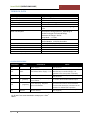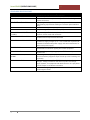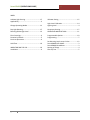
1
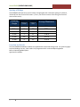
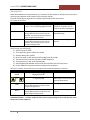
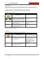
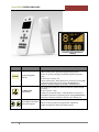
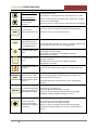
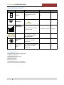
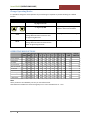
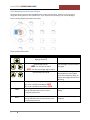
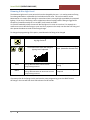
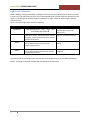
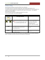
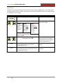
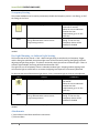
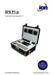
SmartSENSOR[OPERATIONS GUIDE] SmartSENSOR StandAlone OPERATIONS GUIDE Content: Operations Description Installation Guide Programming Manual 1 v2.0 SmartSENSOR[OPERATIONS GUIDE] v2.0 Contents Introduction .................................................................................................................................................. 3 Applicability............................................................................................................................................... 3 Installation .................................................................................................................................................... 4 Spacing of fittings...................................................................................................................................... 5 Function by Default ............................................................................................................................... 5 Start Up Test ............................................................................................................................................. 6 Programming ............................................................................................................................................ 7 Indicator on the LCD ........................................................................................................................... 10 Programmable Options ........................................................................................................................... 10 Change Operating Modes ................................................................................................................... 11 Set Dimming Levels across Circles ...................................................................................................... 12 Dimming & Max Light Level ................................................................................................................ 13 Light Level Calibration ......................................................................................................................... 14 IR Power Setting .................................................................................................................................. 15 Hold Time ............................................................................................................................................ 16 Occupancy Sensing.............................................................................................................................. 17 Day Light Dimming, or Ambient Light Sensing .................................................................................... 17 Attachments:........................................................................................................................................... 17 2 SmartSENSOR[OPERATIONS GUIDE] v2.0 Introduction SmartSENSOR is an Energy Efficiency Controller for LED Panels and Dimmed fittings. It uses 110v DC dimming technology to provide control to the connected fittings. SmartSENSOR utilises Occupancy Sensing and Daylight Harvesting components and programming to deliver energy Efficiency and reduced power consumption. SmartSENSOR is delivered in 2 forms: 1) SmartSENSOR LED PANEL: These fittings are JeWoo LED Panels fitted with SmartSENSOR arrays in the edge strip. They can be mounted conventionally in a TBar ceiling, or be supplied with a Pendant Mounting Kit. The fittings are typically 300mm x 1200mm, 600mm x 600mm, or 600mm x 1200mm. These units only need a 220-240Vac supply. There is no control cabling required. not be any type or style, as long as they are controlled by a 1-10v Dimming Driver or Dimmer This type of controller is ideally suited to conference rooms and managers offices. Any smaller office with reduced numbers of fittings. SmartSENSOR StandAlone is also perfect for situations where the client requires lights other than LED Panels. As long as the fittings can be supplied in 1-10V Dimmed format the SmartSENSOR StandAlone will provide all the control and energy efficiency you need. 2) SmartSENSOR StandAlone This controller can be used in smaller rooms where there may be a need for only one sensor. There may be 4 -6 fittings, though the size of the room enables one sensor to amply cover the occupancy detection function. Thereby saving a quantity of sensors, while still giving ample control of the lighting. The fittings controlled need 3 Applicability This document applies to SmartSENSOR StandAlone. SmartSENSOR LED Panels are covered by a separate document. SmartSENSOR[OPERATIONS GUIDE] v2.0 Installation SmartSENSOR StandAlone was introduced to address the need to control lights (typically already installed lights) in smaller spaces. Spaces where there were 4 or 6 fittings, and the space could be occupancy sensed by a single, centrally located, occupancy sensor. Following from that we could save the cost of 3 or 5 sensors (depending on numbers of installed fittings). While providing functional control similar to that provided by the SmartSENSOR system, along with similar savings in energy consumption. The Central sensor module performs the same occupancy and ambient light sensing as in the LED Panel mounted version. However its centralized control is spread to the other fittings through control cabling. The Control cabling is either existing or will need to be added. The advantage of this type of system, is that all of the work for installation can be performed in the ceiling space, near the existing fittings. The Central Sensor is supplied with I/R Transmission capability. (But, you said there is only need for 1 sensor? So why would it need to communicate? ) We have found in practice that there are some instances, where smaller rooms with a small number of fittings, still need 2 sensors to get good occupancy coverage. Allowing for furniture and other I/R obstacles. Therefore we have maintained I/R transmission and receipt as integral functions of these sensors as well. There are several things to consider: The Lighting Level within the Space The plan for lighting layout should be completed by a suitably qualified person using a Lighting Design program. This program will take into account the light fitting characteristics as contained in the .ies file. Along with making allowance for wall ceiling and floor colours, ambient light contribution, and all the factors which influence the amount of light required in a given space. The program will ensure the lights are placed to deliver the required overall specified lighting level. The fittings may be existing and therefore this planning will not be required. The .ies file for any fitting available by contact with the JeWoo Marketing Staff. Floor Coverings Light colour solid surfaces will serve best the interfitting communication. Carpets must be short pile. Furniture placement Furniture placement may effect the operation of the system and will need to be tried and tested to ensure best location and system operation. 4 SmartSENSOR[OPERATIONS GUIDE] v2.0 Spacing of fittings SmartSENSORs will operate at up to 3.0metre ceiling heights and a maximum spacing of 3.6metres, measured from the centre of the sensors. (That is, not from the centre of the fitting, but from the centre of the sensor) Mounting Height Spacing Fixture to Fixture to Fixture Wall 2.5m 2.5m 3.0m 3.0m 3.5m 3.5m 2.4 3 2.4 3 2.4 3 1.2 1.5 1.2 1.5 1.2 1.5 Average Illuminance 436 lx 285lx 424 lx 278 lx 411 lx 272 lx All Measurements in Metres Function by Default The SmartSENSOR StandAlone modules are supplied with customized setting mode. For optimizing Light Level and Holding time etc., Each needs to be programmed with a selected Operating Mode. Refer to Operating Mode Option. Light Sensor is disable. 5 SmartSENSOR[OPERATIONS GUIDE] v2.0 Start Up Test When the Standalone is first powered up, it is necessary for the installer to initiate a short self test to ensure proper operation and connection of the fitting it controls. The work is best done at night when no ambient light interferes with the process. To initiate the Self Test : PRESS DISPLAY COMMENTS FUNCTION Keep Pressing (press … Press … Press …etc) until the Big Digit flashes 1 Big Digit Flashes 1 directly in case Press “Function key” for initial set up after opening box SEND BRCST SEND image flashes for 1 second Fitting’s RED LED Flashes 2 times and the indicator stay on during the test to show to show “Programming Received” SEND image flashes for 1 second Fitting’s RED LED Flashes 2 times and the indicator stay on during the test to show “Programming Received” This runs the self-test on an individual fitting Broadcast to other fittings if required Once running, the SelfTest will: 1) Take its output to 100% 2) The output then goes to off for one second 3) Switches back to On at 100% 4) Dims from 100% to 10% and from 10% to 100% over 30 seconds 5) The luminaire then resumes operation at 100% brightness 6) The Light sensor is now set up automatically. 7) Sensor Module LED Indicator will be off at the end of the Start Up Test process. 8) In case of BRCST, Intercommunication testing is also carried out. After this is complete, the unit will need to be programmed for Operating Mode by an operator. PRESS DISPLAY COMMENTS SCENE Big Digit flashes 2 or 4th Digit steps 0-9 SEND BRCST Step through to the Operating Mode required. Refer to the list of Operating Modes below SEND image flashes for 1 second Fitting’s RED LED Flashes 2 times to show “Programming Received” This programs an individual fitting SEND image flashes for 1 second Fitting’s RED LED Flashes for 60 seconds to show “Programming Received” Broadcast to other fittings if required Note : during the broadcast, it is inactivated to receive another function signal. CONGRATULATIONS ! ….You have completed all the necessary programming for the normal operation of the fitting and its nearby neighbours. 6 SmartSENSOR[OPERATIONS GUIDE] v2.0 Programming All programming of the fittings is performed with a Remote Control Handpiece. This device will allow the user to change some of the parameters of the system to tailor performance to suit the specific needs of the client. In addition to programming, the Remote Handpiece is a handy manual operating tool. The Remote enables the user to switch the fitting ON and OFF, as well as dimming. Dimming all the lights in the room is easy. PRESS DISPLAY COMMENTS Big Digit flashes 7 or SEND BRCST Display is fully lit. There is no indication of movement in dimming level other than the state of the light fitting you are adjusting. Use keys to set the light to the desired level. SEND image flashes for 1 second Fitting’s RED LED Flashes 2 times to show “Programming Received This programs an individual fitting. The dimming level is set as adjusted. SEND image flashes for 1 second Fitting’s RED LED Flashes for 60 seconds to show “Programming Received” Broadcast to other fittings if required Note : In case Photo Sensor and Motion sensor were set up as “ON”, then they become temperately disable for 1 minute after setting dimming function. ON & OFF To switch the fitting ‘ON’ and ‘OFF’ simply press the appropriate button PRESS DISPLAY COMMENTS Use keys to set the light to the Big Digit flashes 0 desired level .…. ON or OFF. SEND BRCST 7 SEND image flashes for 1 second Fitting’s RED LED Flashes 2 times to show “Programming Received SEND image flashes for 1 second Fitting’s RED LED Flashes for 60 seconds to show “Programming Received” This programs an individual fitting. Occupancy and Ambient light Sensors are disabled. They must be reset to ‘ON’ to allow the fitting to perform automatically Broadcast to other fittings if required SmartSENSOR[OPERATIONS GUIDE] v2.0 Remote Control HandPiece Display Symbol Purpose For Operating Mode selection For MAX_LEVEL programming Operation Short pressing once within one second to advance next scene and Enables selection of the appropriate programming function. Use the, , , keys to change the required programming option cycling : (up count) 0->1→2→3→…→9 or (down count)9→8→…0Once Selected it is necessary to Press SEND to upload the programming to the Fitting OR BROADCAST if necessary to send the program to all units in the defined area Short pressing once within one second to advance next percentage and cycling : (up count) 10->20…->100 or (down count) 100->90→80→…→10e Selected it is necessary to Press SEND to upload the programming to the Fitting OR BROADCAST if necessary to send the program to all units in the defined area Selects digit of the Display Used for a variety of programming parameter adjustments. that will be adjusted Changes the digit of the display that will be altered 8 SmartSENSOR[OPERATIONS GUIDE] v2.0 Non programming mode : Non programming mode : Dimmer buttons Dimmer buttons. Allowing the Dimmer to be adjusted up or down Programming Mode: Increase or Decrease set level of selected parameter Used for a variety of programming parameter adjustments. Changes the value of the selected digit. Cycling from 9 to 0 by key or from 0 to 9 by key for selected digit Use the, ►, ◄, keys to select digits to change Use the, , , keys to change the IR power level the parameter. IRPWR For increasing or decreasing Infrared power Parameter is from 1 to 31 as maximum power. For sending the programme parameter values and commands by IR to SENSOR module Pressing once this key to send The LED send display will flash for 1 second. The Fitting’s RED LED will Flash two times to show it has received programming Press once to enable if it is disable (icon appears on the LCD screen). Pressing again this key to disable. Once Selected it is necessary to Press SEND to upload the programming to the Fitting Press once to enable if it is disable (icon appears on the LCD screen). To enable/disable motion Press again to disable. sensor Once Selected it is necessary to Press SEND to upload the programming to the Fitting To enable/disable photo sensor To toggle lighting status of On / Off Lighting Fitting. Use send to turn on/off 1 fitting or BRCST on / off All fittings in the luminaire area. BRCST HOLD TIME To broadcast parameters, previously set in a single fitting, to all luminaires by transmitting from sensor to sensor Pressing causes the programming entered to a fitting to be broadcast from the receiving fitting to all other fittings in the defined area. SEND image flashes for 1 second Fitting’s RED LED Flashes for 60 seconds to show “Programming Received” To control the period of Press to enter in to holding time lights stay ON after the Use the, ►, ◄, keys to select digits to change last occupancy trigger Use the, , , keys to change the levels of the selected digits Use SEND to 1 fitting or BRCST All fittings in the area. To enter into/finish setting the percentage dimmed value to apply for a Circle level. 9 Press to enter into Circle Level setting function. Use the, ►, ◄, keys to select digits to change Use the, , , keys to change the levels of the selected digits Terminate percentage setting if no arrow key is pressed within 60 seconds. SmartSENSOR[OPERATIONS GUIDE] v2.0 INDICATORS ON THE LCD Symbol Name Function Purpose One digit display for Scene Indication Display Range 0~9 Default – Turns ON for 1 second flash after SEND IMAGE pressing LUMINOUS OUTPUT SCALE – – 10 ~ 100 (%) step by 10% 100 (%) key Ten scale line bar for Luminous Output Percentage These indicators have several uses, depending on what is being programmed Photo Sensor State This indicator will be displayed, If photo sensor is enabled. Otherwise Off. – – Motion Sensor State This indicator will be displayed, If Motion sensor is enabled. Otherwise Off – – Programmable Options The Parameters that can be changed follow: Change operating Modes Set Dimming Levels across Circles Hold Time for Full Level Maximum Light Level IR Output Power Level Dim Individual fittings (or a whole group) Ambient and Occupancy Sensing Operation 10 SmartSENSOR[OPERATIONS GUIDE] v2.0 Change Operating Modes It is possible to change the mode operation of just one fitting or if required any number of fittings in a defined location. PRESS DISPLAY SCENE Big Digit flashes 2 or 4th Digit steps 0-9 SEND BRCST COMMENTS Step through to the Operating Mode required. Refer to the list below SEND image flashes for 1 second Fitting’s RED LED Flashes 2 times to show “Programming Received This programs an individual fitting SEND image flashes for 1 second Fitting’s RED LED Flashes for 60 seconds to show “Programming Received” Broadcast to other fittings if required OPERATING MODE OPTIONS 0.User-defined 1.Open Floor 2.Corridor 3.Closed Office 4.All on all times 5.Amenities 6.super saver 7.Close&Tight 8.No windows 9. Warehouse Hold Time Max Circle Circle Circle Circle Circle Circle Circle Circle Circle Lowlight level 1 2 3 4 5 6 7 8 9 Level 10s 30s 30s 15 min 10 min 10 min 5 min 10 min 15 min 15min 100% 100% 100% 100% 100% 100% 100% 100% 100% 100% 90% 0% 0% 0% 0% 0% 0% 0% 0% 40% 10% 0% 0% 0% 0% 0% 0% 0% 10% 0% 0% 0% 0% 0% 0% 0% 0% 80% 10% 10% 10% 10% 10% 10% 10% 10% 100% 100% 100% 100% 100% 100% 100% 100% 100% 100% 50% 50% 10% 10% 10% 10% 10% 10% 100% 40% 10% 0% 0% 0% 0% 0% 0% 50% 0% 0% 0% 0% 0% 0% 0% 0% 100% 80% 80% 40% 10% 10% 10% 10% 10% 100% 70% 40% 10% 10% 10% 10% 10% 10% Note All the parameters are editable by user only in User-defined mode. ONLY Hold time and Max level can be changed by user in rest of 9 modes from no. 1 to 9. 11 7% 10% 10% 10% 100% 10% 10% 10% 10% 10% Lowlight Hold Time 5s 5s 5s 15s 10s 5s 5s 10s 15s 10s SmartSENSOR[OPERATIONS GUIDE] v2.0 Set Dimming Levels across Circles Dimming levels are set by the Operating Mode that the fitting operates within. However a User may wish to change the dimming levels to suit a specific need. Any or all of the Circle Dimming Levels can be changed. This is how the fittings work within the circles: There are 9 possible Circles. PRESS DISPLAY COMMENTS Big Digit flashes 3 or Selected digit flashes 1000 – for the circle to adjust Left and Right to Move between the digits 1000 – for the ‘percentage’ digit to adjust or Selected Digit steps 1-9 Select the leftmost digit and choose which circle to adjust. Then select each other digit, to load a percentage value of circle dimming When you have the required percentage … Eg: Circle 3 at 50% would display 3050 Or, Circle 3 at 100% would display 3100 SEND BRCST 12 SEND image flashes for 1 second Fitting’s RED LED Flashes 2 times to show “Programming Received This programs an individual fitting SEND image flashes for 1 second Fitting’s RED LED Flashes for 60 seconds to show “Programming Received” Broadcast to other fittings if required SmartSENSOR[OPERATIONS GUIDE] v2.0 Dimming & Max Light Level The Maximum Light Level is a set point which can be changed by the user. It is used to prevent a fitting from being switched on at (dimmed to) a level above the set value. This can be used for Lumen Maintenance or to ensure extra savings in areas where there is too much light provided by the powered lighting. To be clear, if the fitting is set to a Maximum value of say 40% and the fitting is triggered for Occupancy (it would normally turn on to 100%) it will switch on to 40%. It is also the method by which the user will dim the lights in his room to a set level. For example in a conference room to dim the fittings to a set level for a projector to be used, one dims the first fitting and then presses broadcast to make all the fittings change. To change the programming of this option, stand beneath the fitting to be changed PRESS DISPLAY COMMENTS Big Digit flashes 7 or SEND BRCST The Luminous Bar Graph will change as lighting level is adjusted. Select the required dimming level. (Maximum dimmed level) SEND image flashes for 1 second Fitting’s RED LED Flashes 2 times to show “Programming Received This programs an individual fitting SEND image flashes for 1 second Fitting’s RED LED Flashes for 60 seconds to show “Programming Received” Broadcast to other fittings if required If necessary that all the fittings in this area have the same programming, press the BRCST button. All fittings in the area will flash their LED indicators for 60 seconds 13 SmartSENSOR[OPERATIONS GUIDE] v2.0 Light Level Calibration When a building is being constructed, the designer will nominate the required level of Lux to be present in each area. The values may vary from area to area depending on the type of activity carried out in that space. To set this type of variable, the work is best done at night. When no ambient light interferes with the process. Go to a convenient light in the area to be adjusted. PRESS FUNCTION SEND BRCST DISPLAY Keep Pressing (press … Press … Press …etc) until the Big Digit flashes 5 The system takes the light level reading from the inbuilt photo sensor. This represents the set level for lighting, used in the calculation of the ambient light level performance SEND image flashes for 1 second Fitting’s RED LED Flashes 2 times to show “Programming Received SEND image flashes for 1 second Fitting’s RED LED Flashes for 60 seconds to show “Programming Received” COMMENTS The display will start at 1 and then step through to 9 with each button press This is a self driven process and requires no input from the user This programs an individual fitting Broadcast to other fittings if required This program stores the high level set point used later in Lumen maintenance, and Ambient light sensing. If necessary that all the fittings in this area have the same programming, press the BRCST (Broadcast) button. All fittings in the area will flash their LED indicators for 60 second 14 SmartSENSOR[OPERATIONS GUIDE] v2.0 IR Power Setting Out of the Box the fittings come with the IR Power set to maximum. The IR Power driver has a 31 position energy range. Factory Default is Max power on ‘31’. It is possible that with excellent floor and ceiling conditions the signal from the incident fitting (the one that gets “occupancy triggered”) is received across more than 1 row of fittings. 2 rows might be performing the same function. The user can alter the I/R level to adjust the sensitivity of the system Go to a convenient light in the area to be adjusted. PRESS DISPLAY COMMENTS the Big Digit flashes 6 IRPWR or SEND BRCST Selected digit flashes 00:31 – for the ‘percentage’ digit to adjust First 2 (Leftmost) digits always = 00 SEND image flashes for 1 second Fitting’s RED LED Flashes 2 times to show “Programming Received SEND image flashes for 1 second Fitting’s RED LED Flashes for 60 seconds to show “Programming Received” Use the UP and DOWN keys to increase or reduce the IR power value. The value is between 01 and 31 Default is Maximum strength, 31. This programs an individual fitting Broadcast to other fittings if required If necessary that all the fittings in this area have the same programming, press the BRCST (Broadcast) button. All fittings in the area will flash their LED indicators for 60 seconds 15 SmartSENSOR[OPERATIONS GUIDE] v2.0 Hold Time The Hold time, the period the lights stay ON after the last occupancy trigger event, is set initially by the Operating mode selected. The User may want to make the time longer of shorter to suit a specific need. To Change this value is simple. PRESS DISPLAY COMMENTS the Big Digit flashes 4 HOLD TIME Selected digit flashes or 0000 0000 LeftMost Digit does not appear equates to time value 1=Seconds 2=Minutes 3=Hours 0000 Left and Right to Move between the digits equates to time amount Maximum: S = 59 M = 59 H = 23 Example : 15 minutes Hold Time would display: 0215 or SEND BRCST 16 Selected Digit steps 0-9 SEND image flashes for 1 second Fitting’s RED LED Flashes 2 times to show “Programming Received SEND image flashes for 1 second Fitting’s RED LED Flashes for 60 seconds to show “Programming Received” Select the leftmost digit and choose which circle to adjust. Then select each other digit, to load an appropriate time This programs an individual fitting Broadcast to other fittings if required SmartSENSOR[OPERATIONS GUIDE] v2.0 Occupancy Sensing The remote Handpiece can be used to permanently disable the Occupancy sensor in one fitting, or all of the fittings in the room. PRESS DISPLAY the Big Digit flashes 9 SEND SEND image flashes for 1 second Fitting’s RED LED Flashes 2 times to show “Programming Received COMMENTS The Display will show running man Icon On and Off. When the correct Indication matches the User requirements, go on to the next step This programs an individual fitting. In this case the Occupancy Sensor will be enabled or disabled Both the Ambient light Sensor and the Occupancy sensor have to be re-enabled by the user when needed. Day Light Dimming, or Ambient Light Sensing The normal state of this control is “ON”. When the light fitting is turned on by an Occupancy Trigger, and the fitting has stabilized, the ambient light senor will be continually checking the lighting level and adjusting the light fitting output. ‘The Sensor continually checks the amount of ambient light. If there is sufficient light available, the fitting will be dimmed towards “OFF”. The Light can turn off completely if there is abundant ambient light. Dropping ambient lighting levels will cause the light to switch back on to ensure the lighting level required is continuously delivered. To alternate the state of the Ambient light Sensor, Go to a convenient light in the area to be adjusted. PRESS DISPLAY COMMENTS The Display will show sun Icon the Big Digit flashes 8 On and Off. When the correct Indication matches the User requirements, go on to the next step SEND SEND image flashes for 1 second Fitting’s RED LED Flashes 2 times to show “Programming Received This programs an individual fitting. In this case the Occupancy Sensor will be enabled or disabled Both the Ambient light Sensor and the Occupancy sensor have to be re-enabled by the user when needed. Attachments: 1 ) Smart Sensor Stand Alone Installation Instructions 2 ) Technical Data 17 SmartSENSOR[OPERATIONS GUIDE] v2.0 TECHNICAL DATA TECHNICAL ELEMENT Power Supply Ambient Temperature Degree of Protection Protection Against Contact with Live Parts Protection Class Product Environment for Use Power Consumption Load Contact Sensor Module Connection EMC Compliance Electrical Safety Compliance Field Serviceable Parts Qualified Ballast / Lamp List COMMENTS 220 – 240V AC, 50/60Hz -20oC …….+45oC IP20 when installed in Luminaire Provided by the Fitting and covers II Indoor with maximum recommended ceiling height of 3.7m Consumption during operation : Depending on Number and type of connected fittings Maximum 10 fittings 1-10v DC Sleep Mode : < 1 watt Output : Control Module: 1-10V DC 10mA Max Via 8 way cable ( Supplied ) CONTROLLER WIRING Connector Label Connects to J7 L Mains Supply J5 SWL The Ballast Mains Supply - Live J5 & J7 N Mains Supply - Neutral J2 + (positive) 1-10V Dimming. Positive input to the Ballast J2 - 1-10V Dimming. Negative input to the Ballast J1 Sensor Module (negative) 18 To control the dimmable ballast output To control the dimmable ballast output. This terminal is also a functional Earth Terminal that should be connected to the chassis for reliable EMC operation Connect this with an 8 core cable. (Cable not Supplied) Sensor Module J2, J5 and J7 are screw terminals to accept up to 1.5mm cables Notes Two connections are provided for Wiring Convenience This is the Switched Live to power the attached and controlled fittings. It is switched off to save power in Standby Two connections are provided for Wiring Convenience 2 SmartSENSOR[OPERATIONS GUIDE] v2.0 STANDARDS SPECIFICATIONS Standard EN 60598-1:2008 Description & Title Luminaires General requirements and tests EN 60598-2-1:1989 EN 62031:2008+A1:2013 Luminaires. Particular requirements Specification for fixed general purpose luminaires Photobiological safety of lamps and lamp systems Guidance on manufacturing requirements relating to non-laser optical radiation safety LED modules for general lighting. Safety specifications EN 61347-1:2008+A2:2013 Lamp control gear General and safety requirements EN 61347-2-11:2002, IEC 61347-211:2001 EN 61558-1:2005+A1:2009 Lamp controlgear Particular requirements for miscellaneous electronic circuits used with luminaires Safety of power transformers, power supplies, reactors and similar products General requirements and tests Safety of transformers, reactors, power supply units and similar products for supply voltages up to 1 100 V Particular requirements and tests for switch mode power supply units and transformers for switch mode power supply Limits and methods of measurement of radio disturbance characteristics of electrical lighting and similar equipment Equipment for general lighting purposes. EMC immunity requirements Electromagnetic compatibility (EMC) Limits. Limits for harmonic current emissions (equipment input current up to and including 16 A per phase) Electromagnetic compatibility (EMC) Limits. Limitation of voltage changes, voltage fluctuations and flicker in public low-voltage supply systems, for equipment with rated current ≤ 16 A per phase and not subject to conditional connection PD IEC/TR 62471-2:2009 EN 61558-2-16:2009+A1:2013 EN 55015:2013 EN 61547:2009 EN 61000-3-2:2001, IEC 61000-32:2000 EN 61000-3-3:2013 EN 62493:2010 19 Assessment of lighting equipment related to human exposure to electromagnetic fields SmartSENSOR[OPERATIONS GUIDE] v2.0 INDEX Ambient Light Sensing ..................................... 17 Applicability........................................................ 3 IR Power Setting .............................................. 15 Change Operating Modes ................................ 11 Light Level Calibration ..................................... 14 Lighting Level ..................................................... 4 Day Light Dimming ........................................... 17 Dimming & Max Light Level ............................. 13 Occupancy Sensing .......................................... 17 OPERATING MODE OPTIONS ........................... 11 Floor Coverings .................................................. 4 Function by Default ............................................ 5 Furniture placement .......................................... 4 Programmable Options ................................... 10 Programming ..................................................... 7 Hold Time ......................................................... 16 INDICATORS ON THE LCD ................................. 10 Installation ......................................................... 4 20 Set Dimming Levels across Circles ................... 12 SmartSENSOR LED PANEL .................................. 3 SmartSENSOR StandAlone ................................. 3 Spacing of fittings .............................................. 4 Start Up Test ...................................................... 5 SmartSENSOR[OPERATIONS GUIDE] 21 v2.0