1
SN82xx SNIC UART Serial Interface User Manual
SN82xx SNIC UART Serial
Interface User Manual
Version:
1.5
Release Date:
September 13, 2013
SyChip LLC reserves the right to make changes in specifications at anytime and without notice. The information
furnished in this user guide is believed to be accurate and reliable. However, no responsibility is assumed by SyChip
for its use, nor any infringements of patents or other rights of third parties resulting from its use. No license is
generated under any rights of SyChip or its supporters unless specifically agreed.
Murata / SyChip
Page 1 of 46
SN82xx SNIC UART Serial Interface User Manual
Release Record
Version Number
Version 0.1
Version 1.0
Version 1.1
Version 1.2
Version 1.3
Version 1.4
Version 1.5
Murata / SyChip
Release Date
12/20/2012
1/31/2013
4/5/2013
4/17/2013
5/6/2013
6/6/2013
9/13/2013
Comments
Extracted from SN82xx EVK User Guide
Initial release
Added certificate import
EVB picture and other minor changes
Soft AP control expanded for dynamic config
Added power up indication and WPS support
Added test scripts (keepalive, reset, roam config, get
client list, etc)
Page 2 of 46
SN82xx SNIC UART Serial Interface User Manual
THE TABLE OF CONTENTS
1.
1.1
1.2
2.
INTRODUCTION ................................................................................................................................. 6
ACRONYMS .......................................................................................................................................... 6
REFERENCES ........................................................................................................................................ 7
RUNNING THE SN82XX SNIC MONITOR ..................................................................................... 8
2.1
SETTING UP THE SN82XX EVK FOR WINDOWS .................................................................................... 8
2.2
ESTABLISHING UART SERIAL CONNECTION ......................................................................................... 8
2.3
DEBUG COMMAND & LOG ................................................................................................................... 9
2.4
CHECK SOFTWARE VERSIONS ............................................................................................................. 11
2.5
NETWORK CONFIG ............................................................................................................................. 11
2.5.1
WiFi On-Off panel..................................................................................................................... 12
2.5.2
Association panel ....................................................................................................................... 12
2.5.3
IP info panel .............................................................................................................................. 15
2.5.4
SNIC demo panel....................................................................................................................... 15
3.
RUNNING THE WEB SERVER DEMO HOSTED BY THE PC .................................................. 16
3.1
DEMO NETWORK CONFIGURATION ..................................................................................................... 16
3.2
WEB BROWSER CONFIGURATION ........................................................................................................ 18
3.3
WEB PAGES ........................................................................................................................................ 18
3.3.1
Server Information ..................................................................................................................... 18
3.3.2
Web Buttons with UART .......................................................................................................... 19
3.3.3
Speed Test ................................................................................................................................. 20
4.
CUSTOMIZE AND DOWNLOAD SNIC FIRMARE ..................................................................... 22
4.1
SPECIFY PRODUCT-SPECIFIC CONFIGURATIONS................................................................................... 22
4.1.1
AP mode parameters .................................................................................................................. 23
4.1.2
STA mode parameters ............................................................................................................... 23
4.2
CUSTOMIZE WEB CONTENT IN FIRMWARE ........................................................................................... 25
4.3
IMPORT TLS CERTIFICATE TO FIRMWARE ........................................................................................... 26
4.4
DOWNLOAD SNIC FIRMWARE ............................................................................................................ 28
5.
5.1
5.2
MISCELLANEOUS CONTROL ....................................................................................................... 32
RESET ................................................................................................................................................. 32
SOFT AP CONTROL ............................................................................................................................. 33
6.
READ SENSOR ................................................................................................................................... 34
7.
GPIO CONFIGURATION ................................................................................................................. 35
8.
SOFT AP FUNCTIONS ...................................................................................................................... 36
8.1
8.2
9.
CONNECTING TO THE SOFT AP ........................................................................................................... 36
WEB PAGES OF THE SOFT AP .............................................................................................................. 37
NVM FUNCTION ............................................................................................................................... 42
10.
TEST SCRIPTS ............................................................................................................................... 43
11.
THIRD PARTY LICENSING INFORMATION ......................................................................... 45
Murata / SyChip
Page 3 of 46
SN82xx SNIC UART Serial Interface User Manual
TABLE of figures
Figure 1 SN82XX EVB configuration for UART interface ............................................................................ 6
Figure 2 Main window and Preference window ............................................................................................. 9
Figure 3 Debug Command & Log Window ................................................................................................. 10
Figure 4 SNICMonitor version ...................................................................................................................... 11
Figure 5 Network configuration screen ........................................................................................................ 12
Figure 6 Get Status response ......................................................................................................................... 13
Figure 7 Scan list ........................................................................................................................................... 13
Figure 8 Association in progress ................................................................................................................... 14
Figure 9 Web server demo network configuration ........................................................................................ 16
Figure 10 Display after Web server demo has been started. .......................................................................... 17
Figure 11 Main page displayed in web browser of the demo ....................................................................... 17
Figure 12 IE Internet options ......................................................................................................................... 18
Figure 13 Demo sever information ............................................................................................................... 19
Figure 14 Web buttons ................................................................................................................................. 19
Figure 15 SNIC monitor display reception of button press ........................................................................... 20
Figure 16 Test up load speed ........................................................................................................................ 20
Figure 17 Test download speed .................................................................................................................... 21
Figure 18 Customize firmware parameters (UART) ..................................................................................... 22
Figure 19 Web configuration ......................................................................................................................... 26
Figure 20 Import TLS certificate ................................................................................................................... 28
Figure 21 Firmware download ...................................................................................................................... 29
Figure 22 Firmware download window ......................................................................................................... 30
Figure 23 Popup box if firmware download fails .......................................................................................... 30
Figure 24 Download firmware command line ............................................................................................... 31
Figure 25 Power up indication....................................................................................................................... 31
Figure 26 Miscellaneous Control .................................................................................................................. 32
Figure 27 Read Sensor................................................................................................................................... 34
Figure 28 Join the soft AP from a laptop ....................................................................................................... 36
Figure 29 Soft AP main page ........................................................................................................................ 37
Figure 30 Scan and join ................................................................................................................................. 38
Figure 31 Status page after join ..................................................................................................................... 39
Figure 32 Network indication on SNICMonitor ............................................................................................ 40
Figure 33 IP configuration ............................................................................................................................. 40
Figure 34 IP information ............................................................................................................................... 41
Murata / SyChip
Page 4 of 46
SN82xx SNIC UART Serial Interface User Manual
TABLE OF TABLES
Table 1 Test scripts........................................................................................................................................ 44
Murata / SyChip
Page 5 of 46
SN82xx SNIC UART Serial Interface User Manual
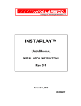
1. Introduction
SN82xx is a complete low power embedded wireless solution to address the connectivity demand in home
appliances and other applications. It integrates an ARM Cortex M3 micro-controller, WiFi BB/MAC/RF
IC, RF front end, flash memory, clock, and on-board antenna into a small form factor module. The
SN82xx Simple Network Interface Controller (SNIC) [2] is a complete platform for easy network
connectivity. The SNIC contains a firmware running onboard SN82xx to support wireless network
configuration, TCP/IP network stack, WiFi driver and I/O peripherals driver. It provides to the embedded
network application a socket interface over a serial bus, enabling the creation of wireless IP-capable nodes
in a simple and straight forward manner. This document provides an overview of the SNIC application
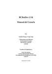
development platform for using a host microcontroller to control SN82xx over UART serial interface. See
[5] for host MCU control of SN82xx over SPI interface; see [4] for hostless web-based application
development based on SN82xx EZ Web Wizzard.
GND pins
CN10: host RXD
CN11: host TXD
CN3
(VDD_IO is middle pin)
CN8: host nCTS
CN9: host nRTS
CN4
(VDD_3V6 is closest to CN3)
Figure 1 SN82XX EVB configuration for UART interface
1.1 Acronyms
Acronym
API
EVB
EVK
FW
GPIO
PC
SNIC
SW
UART
USB
Murata / SyChip
Meaning
Application Programming Interface
Evaluation Board
Evaluation Kit
Firmware
General Purpose Input/Output
Personal Computer
Simple Network Interface Controller
Software
Universal Asynchronous Receiver/Transmitter
Universal Serial Bus
Page 6 of 46
SN82xx SNIC UART Serial Interface User Manual
1.2 References
[1]
[2]
[3]
[4]
[5]
[6]
SyChip, “SN82XX EVB schematics”
SyChip, “SN82xx SNIC Serial Interface Specification”
SyChip, “SN82xx SNIC EVK+ User Guide”
SyChip, “SN82xx SNIC EZ Web Wizzard Development Platform User Manual”
SyChip, “SN82xx SNIC SPI Sample Application User Guide”
SyChip, “SN82xx EZ Web Wizzard Simple Web Services URIs”
Murata / SyChip
Page 7 of 46
SN82xx SNIC UART Serial Interface User Manual
2. Running the SN82xx SNIC monitor
The SN82xx SNIC monitor is a PC application that provides a GUI for feature visualization and validation.
The tool provides an interface to control the SN82xx through the UART, display and log the SNIC
interface exchange, and configure the WiFi access and network connection. It also contains a web server
sample application for demonstrating internet connectivity.
2.1 Setting up the SN82xx EVK for Windows
SNIC monitor must be installed along with the drivers for the SN82xx EVK. The procedures for those
operations are detailed in SN82xx SNIC EVK+ User Guide ([3]).
2.2 Establishing UART serial connection
The following steps are used to configure the serial connection. Ensure that the UART port is not also
being used by the EZ Web Wizzard based web-interface ([4]).
Ensure the SN82xx EVK has been setup properly and the PC drivers have been installed
Press reset (white) button on the SN82XX EVB.
Find the serial port number using the PC’s Device Manager (See SN82xx SNIC EVK+ User Guide
([3])). E.g., COM29.
Double click on SNICMonitor shortcut on PC’s desktop to start the SN82xx monitor application.
Select the File->Preference dialog to configure the serial port. The port number and baud rate are
kept in Windows Registry, other parameters are not persistent. Set the proper value and click OK.
The preinstalled SN82xx FW image uses the following UART parameters. Otherwise, use the
corresponding values for any customized FW image created using the steps in Section 4.
921600 Kbps
8 data bits
no parity
1 stop bit
no flow control
Murata / SyChip
Page 8 of 46
SN82xx SNIC UART Serial Interface User Manual
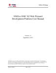
Figure 2 Main window and Preference window
Once the serial port is setup, either use the File->Connect or the Connect button on the tool bar to connect
the tool to the serial port. If the connect command is successful, the “Debug Command & Log” screen will
appear (Section 2.3).
Use File->Disconnect or the Disconnect button on the tool bar to disconnect the serial port.
2.3 Debug Command & Log
This window is useful for monitoring and debugging the serial interface. The upper part of the screen is the
console window, similar to a hyper terminal except it does not allow typing commands to it. It displays the
packets being exchanged through the serial port.
The main display area shows the UART traffic between the host PC and the SN82xx. Messages starting
with [OUT] are coming from the SNICMonitor to the SN82xx. They are encoded messages using the serial
protocol (refer to [2] for details). The messages starting with [IN] are pure payload data (decoded by
SNICMonitor), coming from the SN82xx to the SNICMonitor.
Murata / SyChip
Page 9 of 46
SN82xx SNIC UART Serial Interface User Manual
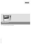
Figure 3 Debug Command & Log Window
The following functions are supported:
“Pause” button is to stop the text from scrolling if too many messages are displayed. “Clear”
button is to clear all the text on the screen.
Choice box “Serial Commands” and the “Send” button are disabled.
“Browse” button is to select a script file.
“Send File” button is to encode and send the content in the script file via UART to the SN82xx.
Script file examples are in the C:\Program Files\Murata\SNICMonitor\test_script folder. All
SNIC APIs can be tested using the scripts. The content of a script file has the following format.
The first byte is the Command ID, the rest is the payload defined by the SNIC interface document
[2]. Every line in the script file must be terminated by a carriage return. See Section 10 for details.
NOTE: Please follow the “Use Cases” section in the interface specification [2] for proper
command sequence when using the scripts. For example, a valid socket must be created before any
command that requires the socket can be used.
The “Repeat” area is mainly for stress test. It applies for both “Send” and “Send File”. It allows
user to send UART commands repeatedly with specified frequency. Default frequency is 10/10=1
transmission per second. “Total times” is the number of times the UART command or file will be
repeated when either the “Send” or “Send File” button is clicked. “Stop” button can stop any inprogress repetition.
Murata / SyChip
Page 10 of 46
SN82xx SNIC UART Serial Interface User Manual
2.4 Check software versions
Software versions include firmware version and SNICMonitor version. Versions should be in the release
note within the release package. There are also ways to check versions at run time.
-
Firmware version:
On the “Debug Command & Log” window, click on “Browse” button and select “ C:\Program
Files\Murata\SNICMonitor\test_script\getFWInfo.txt”. Click on “Send file”. The response in
the window should show the version string returned by the firmware. E.g., [IN] Command:
0x1 Length: 12 Payload:
88 33 00 08 30 32 2E 33 35 31 30 31
The response format can be found by searching GEN_FW_VER_GET_RSP in reference [2].
The ASCII code for the version string starts from the 5th byte until the end. This example
shows the firmware version of “02.35101” which has the ASCII sequence {30 32 2E 33 35 31
30 31}.
-
SNICMonitor Version:
Click on the ? button on the toolbar on the SNICMonitor. The following screen showing the
version string appears.
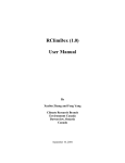
Figure 4 SNICMonitor version
2.5 Network Config
Click on the green “N” button on the tool bar to bring up the network configuration screen. This window
provides the capability to configure WiFi access parameters, IP network configuration and running the web
server demo.
When the window opens, a “Get Status” action will be called internally and the current WiFi status similar
to Figure 6 will be displayed for a couple of seconds.
Murata / SyChip
Page 11 of 46
SN82xx SNIC UART Serial Interface User Manual
Figure 5 Network configuration screen
2.5.1 WiFi On-Off panel
This panel supports the commands to power the WiFi device on and off.
Select the “On” radio button to power up and initialize the WiFi device
Select the “Off” radio button to de-initialize and power off the WiFi device
NOTE: SN82xx supports both soft AP mode and STA mode at the same time. WiFi is turned on by default
at startup. This is to start the soft AP mode for target AP selection.
2.5.2 Association panel
Once the WiFi device is on, WiFi networking can be controlled using the following steps.
Click on “Get Status” button to get the current WiFi status.
Murata / SyChip
Page 12 of 46
SN82xx SNIC UART Serial Interface User Manual
Figure 6 Get Status response
Click on “Scan” button to get a list of APs or Ad Hoc networks.
Figure 7 Scan list
Note: if RSSI shows +127dBm, it means an accurate RSSI value cannot be obtained at that time.
Highlight a SSID and click on “Select SSID”, the scan list window will disappear, the SSID and
Security info will be populated in the “Network Config” window.
To associate with an AP, enter the SSID, security type and security key for the AP and click on
“Join Network” button. If the join is successful, the button is disabled (gray out) and there should
be a “STA Network up” notification; otherwise, a failure notification should popup.
If joining is successful, the RSSI reading will be updated periodically. The SSID field will be
updated to the joined SSID. The “Security” field is not updated after the join because the “STA
Network up” indication does not contain security information.
Note: if user does not want the periodic RSSI update, do the following:
Murata / SyChip
Page 13 of 46
SN82xx SNIC UART Serial Interface User Manual
o
o
Joined the desired AP
Disconnect UART by clicking Disconnect button on SNICMonitor, or simply close and
reopen SNICMonitor program.
o Connect UART by clicking Connect button on SNICMonitor
o Reset SN82xx EVK
o Immediately click on the “N” button on SNICMonitor
o SNICMonitor should pop up a box saying “WiFi off” which is temporary. The SN82xx
will reconnect to the previous AP driven by NVM. If the pop up box already shows
connected status, it means the “N” button is clicked too late. Repeat the process.
o Click on “Get Status” to refresh the real status. RSSI will not be updated periodically.
If the SSID does not exist or if the key is wrong for WPA/WPA2, it may take about 8 seconds to
get a join failure response. A progress bar is displayed during any attempts of association.
Figure 8 Association in progress
If the WiFi link is down after association, a “STA Network Down” notification shall appear. If the
WiFi link is reconnected, a “STA Network UP” notification shall appear. But actual network
availability may delay around 15 seconds in that case depending on AP brands.
To disconnect from existing association, click on “Leave Network” button. After this button is
clicked, the “Join network” button should be enabled. The “SNIC_IP_CONFIG”,
“SNIC_GET_DHCP_INFO”, “SNIC_SEND_ARP”, “SNIC_Resolve_Name” and “Start Web
Server” should be disabled. Use it to reinitialize the screen if the SNICMonitor state is out of sync
with the SN82xx.
Murata / SyChip
Page 14 of 46
SN82xx SNIC UART Serial Interface User Manual
2.5.3 IP info panel
After joining a network, click on the “SNIC_INIT” button first, and then configure IP address using the
following steps.
If dynamic IP addressing is desired, check “DHCP”.
SN82xx will automatically use DHCP to obtain an IP address from the server. Note: even if the
operation is successful, the assigned IP address information is not shown yet. See 2.5.4.
For static IP address, uncheck “DHCP” and enter the IP address information.
Click on “SNIC_IP_CONFIG” button. If successful, the “SNIC_GET_DHCP_INFO” should be
enabled.
2.5.4 SNIC demo panel
This panel is used to show certain SNIC command and control the web server demo application.
“SNIC_INIT” button is the first button that needs to be clicked after association. The button will
change to “SNIC_CLEANUP” after the click is done.
Click on “SNIC_GET_DHCP_INFO” to verify connection is successful by checking if IP address
is shown correctly. Only after this step is done, the “SNIC_SEND_ARP”, “SNIC_Resolve_Name”
and “Start Web Server” buttons will be enabled.
Key in a valid IP address (e.g., another device on the network) and click “SNIC_SEND_ARP” to
get the MAC address of the network interface.
If Internet connection is available, click on “SNIC_Resolve_Name” button to get the IP address of
murata-ws.com or other domain names.
Click on “Start Web Server” to start the sample web server. The button will change to “Stop Web
Server” if successful. See Section 3 for details.
Note: After this point, the correct button click order to stop the demo is: “Stop Web Server”,
“SNIC_CLEANUP”, “Leave network”, “Off”.
Murata / SyChip
Page 15 of 46
SN82xx SNIC UART Serial Interface User Manual
3. Running the web server demo hosted by the PC
The demo illustrates a way to implement a web server using the SN82xx SNIC platform over UART. The
PC is the host processor which connects to the SN82xx module through a UART interface. The sample
HTTP server runs on the PC using the serial interface to communicate with the SN82xx embedded WiFi
network controller. The HTTP request and response are exchanged through the SNIC UART API between
the host and the SN82xx module. The SN82xx module in turn connects to a WiFi access point to provide
wireless connectivity to a network client running a web browser.
3.1 Demo network configuration
The demo configuration is shown in Figure 9 and requires the components listed below:
an SN82XX EVB preloaded with the SNIC FW configured for UART serial interface
SN82xx SNIC monitor running the sample web server application
a WiFi b/g/n access point
a web browser running on a network client device connected to the WiFi access point (wired or
wireless)
AP
WiFi or
Ethernet I/F
WiFi I/F
PC (HTTP server)
SN8200 (TCP/IP + WiFi)
HTTP client
Mini-USB connector
UART I/F
Network server
Network client
Figure 9 Web server demo network configuration
To run the demo, the following steps must be performed:
1.
Ensure that the EVK is setup properly (SN82xx SNIC EVK+ User Guide ([3]).)
2.
Run the SN82xx SNIC monitor (Section 2)
3.
Connect the SN82xx to the AP and obtain IP address for the web server (Section 2.5)
4.
Start the web server demo (Section 2.5.4)
5.
Connect a smart phone or laptop PC to the WiFi AP and start a web browser.
6.
On web browser, key in the IP address shown in the “IP address” field in “Network Config”
window, as illustrated in Figure 10 and Figure 11.
Murata / SyChip
Page 16 of 46
SN82xx SNIC UART Serial Interface User Manual
Figure 10 Display after Web server demo has been started.
Figure 11 Main page displayed in web browser of the demo
Murata / SyChip
Page 17 of 46
SN82xx SNIC UART Serial Interface User Manual
3.2 Web browser configuration
Set web browser options so that it sends out HTTP requests every time when a button is clicked. In another
word, the browser should not use any cached information. For example, Internet Explorer users can open
Tools->Internet Options->Browsing history->Settings, and set the “Check for newer versions of stored
pages:” to “Every time I visit the webpage”.
Figure 12 IE Internet options
3.3 Web pages
The sample web server demo serves web pages that support the following:
Retrieve information about the web server application
Web buttons to demonstrate sending button presses to the host application
Measure up-load and download speed through the UART interface.
3.3.1 Server Information
The page provides information about the web server demo, including version number, platform and IP
address.
Murata / SyChip
Page 18 of 46
SN82xx SNIC UART Serial Interface User Manual
Figure 13 Demo sever information
3.3.2 Web Buttons with UART
The page provides web buttons to demonstrate sending button presses to the host application. Click on any
button.
Figure 14 Web buttons
The SNICMonitor should pop up a message window as shown below. Click on OK to dismiss it; otherwise,
the next button click would not show.
Murata / SyChip
Page 19 of 46
SN82xx SNIC UART Serial Interface User Manual
Figure 15 SNIC monitor display reception of button press
3.3.3 Speed Test
The page can be used to measure the up-load and download speed through the UART interface. The baud
rate of the serial interface significantly restricts the end to end data rate so that the capability of the WiFi
over the air throughput is not reflected in the test.
NOTE:
-
To observe higher speed, it is recommended to disable the Debug print on the SNICMonitor by
uncheck the “Show Debug” checkbox on the Debug Command & Log window.
-
If the “Upload Speed” test result is much less than the below figure, that is possibly due to the
slowness of the host PC which cannot handle COM port fast enough. Use a newer PC in that case.
-
The web server in the SNICMonitor is for demo only. It is not guaranteed to work if multiple
speed test sessions are operating at the same time.
Click on “Test Upload Speed”. The browser will send data to the sample web server.
Figure 16 Test up load speed
Click on Test Download Speed. The sample web server will send data to the browser through
the UART to the WiFi interface.
Murata / SyChip
Page 20 of 46
SN82xx SNIC UART Serial Interface User Manual
Figure 17 Test download speed
Murata / SyChip
Page 21 of 46
SN82xx SNIC UART Serial Interface User Manual
4. Customize and download SNIC Firmare
The SNIC Monitor provides the capability to customize the serial interface, generate a new firmware and
download that firmware.
4.1 Specify product-specific configurations
Application developers can modify the firmware startup parameters to suit their needs. The default software
package released by Murata has a prebuilt binary firmware file for SN82xx. This file will be the input to
generate a new binary firmware file to include any customized parameters.
Figure 18 Customize firmware parameters (UART)
Execute the following steps to generate a new firmware suited for the customer platform.
Open SNIC monitor and click on the green “C” configuration button on the tool bar. It does not
matter if the UART Connect button has been clicked or not. The following window should appear
(with Connect button clicked previously).
Murata / SyChip
Page 22 of 46
SN82xx SNIC UART Serial Interface User Manual
Click the Browse button to select source firmware file, and click on Load button. This will
populate the above fields according to the file. After loading, the Save Firmware button should be
enabled.
The upper left area is interface configuration. Choose the tab panel for UART configuration. Set
the UART parameters used by the host for the serial interface protocol. Do not click on SPI tab,
because it is for a different host application that communicates with SN82xx via SPI interface.
Modify any parameters for the following:
o AP mode parameters (4.1.1)
o STA mode parameters (4.1.2)
Select or type in the name of the target firmware file name.
Click on Save Firmware button. A message should pop up to indicate success or failure.
Continue to the Section 4.2 to import web contents into the newly generated Firmware.
4.1.1 AP mode parameters
The Soft AP Config block specifies the startup parameters for the soft AP interface.
Soft AP on: Soft AP will be on or off at startup
DNS server: if enabled, it will return IP address for the value specified in the Domain name field
(default is sn8200.com).
DHCP server: if enabled, it will assign IP addresses to devices connected to it.
Web server: if enabled, it will serve pages for STA to select a target AP, see details in Section 8.2.
Country code: default is US.
Security: OPEN, WPA-TKIP, WPA-AES, WPA2-AES, or WPA2-MIXED
Pass phrase: 64 characters or less
Channel: WiFi channel for soft AP
SSID Prefix: this is broadcasted soft AP’s SSID prefix
Append MAC to SSID: if checked, the soft AP’s SSID will be the prefix plus the last 3 bytes of the
MAC address; otherwise, the SSID prefix will be used as the whole SSID.
Domain name: default is sn8200.com, can be modified to any name.
The edit box next to the Domain name is the HTTP port for the web server, default is 80.
IP: default is 172.31.0.1, can be customized to be any valid IP.
Subnet mask: default is 255.255.0.0.
Gateway: should be same as IP.
4.1.2 STA mode parameters
The STA Config block specifies the startup parameters for STA interface.
SSID to connect: enter SSID to connect when the module boots up (or after a reset).
Security: the target AP’s security mode which can be OPEN, WEP, WPA-TKIP, WPA-AES,
WPA2-AES, or WPA2-MIXED.
Pass phrase: the target AP’s pass phrase.
Retry itvl (T1): if the SSID specified is not on (or with wrong security settings) at the time
SN82xx boots up, the auto-joining will fail. This parameter specifies the initial retry interval. If
Murata / SyChip
Page 23 of 46
SN82xx SNIC UART Serial Interface User Manual
STA fails to connect for the first time, STA waits for T=T1. Once T expires, STA retries
connection. Failed attempt will result in next attempt at T=min(2*T, Tmax). The unit of timeout
is second(s), and the range is from 0x0000 - 0xFFFF. The value of 0 has a special meaning for T1,
which indicates no retry.
NOTE: this is only supported in SN82xx EVK+ and not SN82xx EVK.
Max itvl (Tmax): maximum retry interval SN82xx waits to retry joining. If T1=10 and
Tmax=1000, the following intervals (seconds) will be set for retries: 10, 20, 40, 80, 160, 320, 640,
1000, 1000, 1000… Either a Join request or a Leave request from other interface (e.g., web) will
stop the retry process.
NOTE: this is only supported in SN82xx EVK+ and not SN82xx EVK.
Internal web server: if enabled, it will serve pages for the STA interface. Default is enabled.
Port: HTTP (internal web server) port, default is 80.
DHCP client: if checked, the module will send DHCP request out to obtain IP after connecting to
AP.
IP, Gateway and Netmask: if DHCP client is not checked, specify the static IP info here.
Hostname prefix: this is the prefix of the hostname that will be advertised through the DHCP host
name option (12). Default value is NUL string which means no hostname is used.
Append MAC to hostname: if checked, the hostname will be the hostname prefix plus the last 3
bytes of the MAC address; otherwise, the hostname prefix will be used as the hostname.
WPS configuration
o
Murata / SyChip
Click on “WPS” button, a window will pop up for user to enter WPS parameters. Click
“Fill with default”, valid default values will populate the fields.
Page 24 of 46
SN82xx SNIC UART Serial Interface User Manual
o
Modify the parameters as needed. The Default Pin is used when Label or Display pin is
selected. If pin length is 7 digits, the 8th checksum digit will be calculated and shown
automatically after “Keep data” is clicked.
o
Click on “Keep data” button. Data will be saved in SNICMonitor’s memory, and window
will be dismissed. Click on “WPS” button again if needed to see what is saved in
memory. The “Save Firmware” button in the Firmware Config window needs to be
clicked to actually save the data to firmware file. If “Keep data” button is not clicked,
WPS parameters will not be saved to memory or the firmware.
4.2 Customize web content in firmware
The soft AP interface in SN82xx includes a built-in web server, see Section 8.2. Customers can modify the
web content to suit their needs. The software package released by Murata has a prebuilt binary firmware
file for SN82xx. This file can be the input to generate a new binary firmware file to include any customized
web content.
Execute the following steps to generate a new firmware suited for the customer platform.
Open SNICMonitor and click on the green “W” configuration button on the tool bar. It does not
matter if the UART Connect button has been clicked or not. The following window should appear.
Follow steps described in [4] to update firmware with customized web contents. Note that the
STA interface described in that document may be reserved for use by the host application using
the UART serial interface. Ensure that the UART port is not also being used by the EZ Web
Wizzard based web-interface ([6]).
Murata / SyChip
Page 25 of 46
SN82xx SNIC UART Serial Interface User Manual
Figure 19 Web configuration
4.3 Import TLS certificate to firmware
The firmware has a default certificate (generated by Broadcom) and private key for secure sockets layer
(SSL) communication. They are used when a secure socket is used or a HTTPS request is sent from the
host application. New certificate and private key can be imported to the firmware by customer using the
SNICMonitor.
The generation of TLS certificate and private key file is out of the scope of this document. Usage of secure
sockets and HTTPS request are described in the SN82xx SNIC UART Sample Application User Guide.
Here is a typical procedure of using a secure socket.
-
TLS TCP server
o
Ensure IP is valid on the interface, either STA or soft AP.
o
Create a secure TCP socket and bind to local IP and a port.
o
Start TCP connection on the socket (listening socket).
o
Accept one incoming connection.
o
Send and receive data on the connection socket.
Murata / SyChip
Page 26 of 46
SN82xx SNIC UART Serial Interface User Manual
-
o
Close the connection socket if no more data needs to exchange on this connection, this
also allows the listening socket to accept new connection.
o
Close the listening socket to terminate the TLS server.
TLS TCP client
o
Ensure IP is valid on the interface, either STA or soft AP.
o
Create a secure TCP socket
o
Connect to a TLS TCP server
o
Send and receive data on the same socket
o
Close the socket to terminate the TLS client
Click on the “T” button to open the certificate import window. Select certificate file, private key file, and
the target firmware file. Certificate and private key files are in BASE 64 format (PEM format). The max
file size of the certificate and private key are 4K and 2K bytes, respectively.
Open the certificate file in a text editor. The certificate should be enclosed between the following two lines.
-----BEGIN CERTIFICATE---------END CERTIFICATE----Similarly, open the private key file in a text editor. The private key should be enclosed between the
following two lines.
-----BEGIN RSA PRIVATE KEY-----
-----END RSA PRIVATE KEY----Click “Import certificate to firmware” button after correct files are selected.
Murata / SyChip
Page 27 of 46
SN82xx SNIC UART Serial Interface User Manual
Figure 20 Import TLS certificate
4.4 Download SNIC firmware
The SN82XX EVB is preloaded with the SNIC FW image. This section describes the procedure for
loading into SN82xx a different SNIC FW image.
1.
Ensure the SN82xx EVK has been setup properly and the PC drivers have been installed
2.
Ensure that there is no other FTDI-based USB connection besides the SN82XX EVB
3.
On SNICMonitor window, click on the green “F” button. It does not matter if the UART Connect
button has been clicked or not. The following screen should pop up (with Connect button clicked
previously).
Murata / SyChip
Page 28 of 46
SN82xx SNIC UART Serial Interface User Manual
Figure 21 Firmware download
4.
The correct SNIC root directory must be entered. By default, the C:\SNIC folder is populated in
the SNIC root directory text box. If it is indeed the SNIC root installation directory, the available
Firmware file should also be shown in Firmware file text box.
5.
If the <Install Folder> is not C:\SNIC, click on the upper Browse button to select the SNIC root
directory. If correct, the Firmware file coming from the installation should be shown; otherwise,
the Firmware file text box is empty. If a firmware file other than the installation version is
desired, click on the lower Browse button to select it.
6.
After SNIC root and Firmware file are selected, select the type of module, e.g., SN8200 or
SN8205. Click on Download button. A black Command screen should show up as below. A
normal download takes about 12 seconds. Press any key to dismiss the Command window when
prompted after firmware download is completed. If the firmware file size is bigger than the
SN82xx’s flash size, an error message is displayed.
Murata / SyChip
Page 29 of 46
SN82xx SNIC UART Serial Interface User Manual
Figure 22 Firmware download window
7.
If the black download screen disappears in a second, the download fails. A popup box should
show the error log location. Check the log for errors. The command line that is actually used to
download firmware should be shown on the Debug window. If the download failed, double check
that the correct values are entered in steps 5-6. It is also possible to do the following to capture
more detailed error messages.
Open a command window by running Start->Run->cmd on PC
Copy the command line from Debug window (see Figure 24) and paste it on the command
window
Hit Enter key to run it.
Check for any error.
Figure 23 Popup box if firmware download fails
Murata / SyChip
Page 30 of 46
SN82xx SNIC UART Serial Interface User Manual
Figure 24 Download firmware command line
8.
After download, press the white RESET button on the SN82XX EVB. Click on UART disconnect
and re-connect button on the SNIC Monitor if necessary. After a reset, there should be a Power Up
indication UART message sent from the SN8xxx to the host. The indication informs the host that
the SN8xxx is ready to receive UART commands from the host.
Note: if startup parameters in NVM have SSID record for the STA, the SN8xxx will first try to
join the SSID. The power up indication will come after the join process. If the join fails, it may
take up to 8 seconds, before the host receives a power up indication.
Figure 25 Power up indication
Murata / SyChip
Page 31 of 46
SN82xx SNIC UART Serial Interface User Manual
5. Miscellaneous Control
Miscellaneous control window has 2 control areas: Reset and Soft AP control. The function is enabled only
after UART is connected to SN82xx.
Figure 26 Miscellaneous Control
5.1 Reset
SN82xx’s firmware can be customized in the Firmware config Window to generate a new Firmware file
(for distribution to market) that has certain start up parameters. For example, SSID, may be set to TXKJ at
startup. But at run time, the SSID may be changed to wlan2007, and saved to NVM. After a reset, SN82xx
will connect to wlan2007. If user wants to revert back to the initial factory default state, i.e., connect to
TXJK at startup, he can call an UART API for this purpose.
An API is defined so that user can restore the SN82xx’s NVM to factory default state. The Reset to factory
default button is a demonstration that this can be done.
Note: this button is not simply for reset purpose, it also restores the NVM to original state.
Murata / SyChip
Page 32 of 46
SN82xx SNIC UART Serial Interface User Manual
5.2 Soft AP control
The WIFI on/off command controls both soft AP and STA at the same time. There is another API to
dynamically only turn on and off the soft AP during run time.
Click “Get AP Status” button to check the current status of the soft AP.
Select either AP on or AP off, the “Set” button will be enabled. Click the “Set” button will set the AP state
to on or off. If the “Save state to flash” is checked, the state will be written to NVM, and next time the
module reset, it will retain the specified AP on off state.
Select “AP on with params” button, the parameters fields will be enabled. This is to change the soft AP’s
parameters at run time. The soft AP will be reset with the new parameters. The parameters will be saved in
NVM if “Save state to flash” is checked, which will override the soft AP parameters shown in “FW
Config” window.
Murata / SyChip
Page 33 of 46
SN82xx SNIC UART Serial Interface User Manual
6. Read sensor
The SN82xx EVB has a SHT21 temperature and humidity sensor installed. The sensor is connected to
SN82xx using the I2C interface. Click on the “S” button to open the Read Sensor window.
Figure 27 Read Sensor
Click on Init button to initialize the sensor, then click the Poll button to refresh the Temperature and the
Humidity readings. Each Poll will update one of those values.
Murata / SyChip
Page 34 of 46
SN82xx SNIC UART Serial Interface User Manual
7. GPIO configuration
SNIC monitor provides user with some command scripts to configure and control spare GPIO pins. To
verify this feature, user needs an oscilloscope or multimeter plus a flying wiring to hook up with the
particular pin under test. Taking PB6 (P43) as an example, use the following scripts in
“test_script\GPIO\PB6” sequentially to configure it as an output pin and toggle its level.
config_output.txt
write_0.txt
write_1.txt
Use the following scripts to configure it as an input and read its level input
config_input.txt
read.txt
Or use
config_input_int.txt
to enable it as interrupt pin. In this case, interrupt indication will be received when it is toggled by an
external source.
Scripts to configure other GPIO pins can be found in folder “test_script\GPIO”.
Murata / SyChip
Page 35 of 46
SN82xx SNIC UART Serial Interface User Manual
8. Soft AP functions
SN82xx supports both soft AP mode and STA mode at the same time. Soft AP is started by default when
powered up, along with DNS server, DHCP server and web server. The web server provides user a sample
web interface to configure the STA to scan and join a target AP. This is useful for a display-less
implementation using SN82xx, i.e., if a device does not have a key pad to enter SSID and security info, it
will not be possible to use the serial command WIFI_JOIN_REQ to join any AP. The soft AP will serve as
the input device in this case.
Use the following steps to access the soft AP functions.
8.1 Connecting to the soft AP
1.
2.
3.
Reset SN82xx.
From a laptop computer with WiFi enabled, scan and join the soft AP’s default SSID: MurataWS-xxxxxxx. The xxxxxx is the last 3 bytes hex of the MAC address of the SN82xx module.
Default security is Open.
The laptop obtains an IP from the soft AP’s DHCP server after joining the soft AP.
Figure 28 Join the soft AP from a laptop
Murata / SyChip
Page 36 of 46
SN82xx SNIC UART Serial Interface User Manual
8.2 Web pages of the soft AP
Make sure web browser’s internet option is set as described in Section 3.2.
The web files used for the soft AP web pages are under <Install folder>\SNIC_UART\webroot, e.g.,
C:\SNIC\SNIC_UART\webroot.
1.
After the laptop joins the soft AP, open a web browser on the laptop. In the address bar, type in
sn8200.com. The following web page should appear. If the STA interface has not joined a
network, the SSID field should be empty.
Figure 29 Soft AP main page
The initial main page is served by index.html, which invokes wifi_sta_status.html showing STA is not
connected to any network.
2.
On the main page, click on “WiFi scan and join” tab. The user can join the WiFi network using
one of the following methods:
o
WiFi protected setup (WPS) using either the PIN or virtual Push Button method
o
Manual configuration by selecting the AP and entering security information.
Murata / SyChip
Page 37 of 46
SN82xx SNIC UART Serial Interface User Manual
Figure 30 Scan and join
3.
Manual configuration with Scan and join panel (skip if WPS is to be used)
Select SSID, enter password and click on Join. When the join is successful, the channel of the soft AP
will change to the channel of the selected AP. Wait for about 10 seconds for the new status. The delay
is due to the channel change of the soft AP, which causes the Laptop to reconnect to the soft AP in the
new channel. The result page is served by wifi_sta_status.html, but two more buttons are added for
options to leave the network or get the signal strength of the current connected AP.
Murata / SyChip
Page 38 of 46
SN82xx SNIC UART Serial Interface User Manual
Figure 31 Status page after join
4.
WPS setup panel (skip if step 3 is used)
For WPS, the SN82xx supports Push Button and Pin mode.
o
When using Push Button mode, press the WPS button on the AP, then click on “WPS Connect”
button on sn8200.com page with “Push Button” mode selected.
o
When selecting Pin mode, a message box on Pin length will appear as shown in the above screen
capture. Use a PC/tablet/smart phone and connect to the AP web page for WPS control. Enter
valid pin into the AP web page and the sn8200.com page, press the WPS button on the AP’s web
page, and then click on “WPS Connect” button on sn8200.com page with “Pin” mode selected. It
may take up to 2 minutes for WPS connection to complete. User needs to click the “WiFi STA
Status” tab to check connection status.
If connection is successful, the SNICMonitor should also receive a Network UP notification from UART
and pops up an information box.
Murata / SyChip
Page 39 of 46
SN82xx SNIC UART Serial Interface User Manual
Figure 32 Network indication on SNICMonitor
5.
At this point, the STA joins the network but has not obtained an IP. Users have two options to get
IP configured. One is to go back to the SNICMonitor and follow steps described in Section 2.5.3.
The other is to click on the “STA IP Configuration” tab on web browser and then click on
“Configure IP” with DHCP or static IP. The result page is served by ip_config.html.
Figure 33 IP configuration
The hostname field is used to specify a hostname to be embedded into DHCP request. When “Append last
3 bytes of MAC to hostname” is checked, the last 3 bytes of MAC address will be appended to the
hostname. Enter “*” if hostname does not need to be changed. Empty the field if hostname is to be erased
so that it would not be embedded into DHCP request.
Murata / SyChip
Page 40 of 46
SN82xx SNIC UART Serial Interface User Manual
Click on “Get IP Info” button to show the IP address information of the STA interface.
Figure 34 IP information
For SNIC serial interface application, the above 3 tabs are sufficient for instructing SN82xx to join/leave an
AP. If there is a need to modify the web content, follow the steps described in [4] to customize the web
pages. Also check out the SNIC EWW firmware to see the web capabilities.
Murata / SyChip
Page 41 of 46
SN82xx SNIC UART Serial Interface User Manual
9. NVM function
Flash space (NVM) is reserved to store startup parameters in SN82xx for both the soft AP and the STA.
The purpose is to allow the SN82xx to join the last SSID and preserve the IP info, if it is restarted for any
reason. Only STA’s parameters can be dynamically changed at run time.
The stored parameters for both soft AP and STA are: Soft AP on/off, Country code, SSID, Passphrase,
Channel, DHCP or static IP, etc. The parameters will be used at power up. They can be configured in the
Firmware configuration screen on the SNIC Monitor (Section 4.1). Whenever the STA tries to join an AP
or obtain IP address, the information is saved in NVM. The latest saved information is used at module
power up. The NVM configuration may be restored to the factory default in the Miscellaneous control
screen on the SNIC Monitor (Section 5.1). Please see reference [2] for details.
Murata / SyChip
Page 42 of 46
SN82xx SNIC UART Serial Interface User Manual
10. Test scripts
Table 1 is the description for the scripts in C:\Program Files\Murata\SNICMonitor\test_script. Not all
scripts are listed. For similar scripts, only one variation is described. Most scripts can be exercised using
the SNICMonitor. Following is the script format. A terminating <CR> is significant at each line of any
script. If multiple lines are specified in a script file, then the delay time between the transmissions of each
line is 1 second by default.
Byte 1
Command ID
Byte 2 … n-1
Command payload
Byte n
<CR>
Check reference [2] for corresponding command payload specification. For example, closeSock4.txt has
the following content.
70 03 33 04 <CR>
Byte 2 … n-1
0x03 0x33 0x04
Byte 1
0x70
-
Byte n
<CR>
0x70 is the command ID for CMD_ID_SNIC
0x03 is the sub-command ID for SNIC_CLOSE_SOCKET_REQ
0x33 is the request sequence number, which can be any number in script testing
0x04 is the Socket number
<CR> is the carriage return
Script
ackCfg.txt
ackNoCfg.txt
arp.txt
closeSock4.txt
connectToServer4.txt
createTCPServerConnection4.txt
getDHCP.txt
getFWInfo.txt
getHostByName.txt
getSockName_local0.txt
getSockName_peer4.txt
getSockOpt.txt
partcloseSock4.txt
sendFromSock4.txt
setSockOpt.txt
setSockOpt_keepalive.txt
setSockOpt_keepcnt.txt
setSockOpt_keepidle.txt
setSockOpt_keepInt.txt
setSockOptMulticast.txt
softReset.txt
TCPConnectToServer4.txt
TCPCreateClientSock.txt
Murata / SyChip
Description
Enable ack in data received indication
Disable ack in data received indication
Send ARP request
Close socket 4
Connect to TCP server using socket 4
Create TCP server socket, the socket number would be 4 if soft AP is
on, and no other sockets are created.
Get DHCP info
Get Firmware version info
Resolve a domain name
Get socket 0’s local IP and port info
Get socket 4’s connected peer’s IP and port info
Get socket option
Partial close socket 4
Send from socket 4 in TCP or connected UDP connection
Set socket option example (SO_REUSEADDR)
Set socket option example (SO_KEEPALIVE)
Set socket option example (TCP_KEEPCNT)
Set socket option example (TCP_KEEPIDLE)
Set socket option example (TCP_KEEPINTVL)
Set socket option for UDP multicast receive
Soft reset the module
Use socket 4 to connect to a TCP server
Create a TCP client socket
Page 43 of 46
SN82xx SNIC UART Serial Interface User Manual
TCPCreateServerSock.txt
udpCreateClientSock.txt
udpCreateRecvSock.txt
udpSendFromSock4_con.txt
udpSendFromSock4_noCon.txt
udpSimpleSend.txt
udpStartRecv4.txt
wifiGetClientList.txt
wifiGetRssi.txt
wifiGetStat.txt
wifiIpConfig_DHCP.txt
wifiIpConfig_staticIP.txt
wifiJoinNoSec.txt
wifiLeave.txt
wifiOff.txt
wifiOn.txt
wifiScanCh.txt
wifiScanSsid.txt
WifiAPOff.txt
WifiAPOnPersist.txt
wifiGetAPStat.txt
wifiSetRoam.txt
Create a TCP server socket
Create a UDP client socket
Create a bound UDP socket
Send from UDP socket 4 in connected mode
Send from UDP socket 4 in non-connected mode
Send to a remote UDP socket without creating a client socket first
Start receiving on bounded socket 4
Get client list that are connected to the soft AP
Get current RSSI
Get current STA status
Configure STA to use DHCP
Configure STA to use static IP
Join an open AP
Disconnect from an AP
Turn WiFi power off
Turn WiFi Power on
Scan by channel number
Scan a specific SSID
Turn off soft AP
Turn on soft AP and save state to NVM
Get current soft AP’s status
Set or get roaming trigger and delta
Table 1 Test scripts
Murata / SyChip
Page 44 of 46
SN82xx SNIC UART Serial Interface User Manual
11. Third party licensing information
The demo application uses the following open source and vendor-specific libraries:
FTDI (libftdi/libusb) open source driver
FreeRTOS open source RTOS
LwIP open source network stack
ARM GNU open source gcc toolchain
STM32F1x library
Cortex-M3 CMSIS
Broadcom WICED SDK
jQuery
The means for obtaining the licenses and sources for those components is located in <Install
Folder>\License & Open Source Related.
Murata / SyChip
Page 45 of 46
SN82xx SNIC UART Serial Interface User Manual
(END)
Murata / SyChip
Page 46 of 46