1
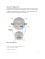
Dell Configuration Guide for the S6000
System
9.5(0.1)
Notes, Cautions, and Warnings
NOTE: A NOTE indicates important information that helps you make better use of your computer.
CAUTION: A CAUTION indicates either potential damage to hardware or loss of data and tells you
how to avoid the problem.
WARNING: A WARNING indicates a potential for property damage, personal injury, or death.
Copyright © 2014 Dell Inc. All rights reserved. This product is protected by U.S. and international copyright and
intellectual property laws. Dell™ and the Dell logo are trademarks of Dell Inc. in the United States and/or other
jurisdictions. All other marks and names mentioned herein may be trademarks of their respective companies.
2014 - 07
Rev. A00
Contents
1 About this Guide................................................................................................. 32
Audience..............................................................................................................................................32
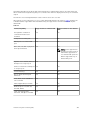
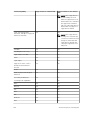
Conventions........................................................................................................................................ 32
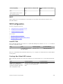
Related Documents............................................................................................................................ 32
2 Configuration Fundamentals........................................................................... 33
Accessing the Command Line............................................................................................................33
CLI Modes............................................................................................................................................33
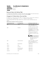
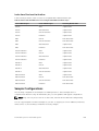
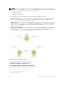
Navigating CLI Modes................................................................................................................... 34
The do Command............................................................................................................................... 37
Undoing Commands...........................................................................................................................38
Obtaining Help.................................................................................................................................... 39
Entering and Editing Commands....................................................................................................... 39
Command History.............................................................................................................................. 40
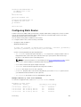
Filtering show Command Outputs.....................................................................................................40
Multiple Users in Configuration Mode............................................................................................... 42
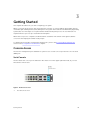
3 Getting Started....................................................................................................43
Console Access................................................................................................................................... 43
Serial Console................................................................................................................................43
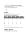
Default Configuration......................................................................................................................... 44
Configuring a Host Name...................................................................................................................44
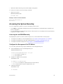
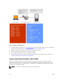
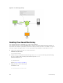
Accessing the System Remotely.........................................................................................................45
Accessing the and S6000Remotely............................................................................................. 45
Configure the Management Port IP Address............................................................................... 45
Configure a Management Route.................................................................................................. 46
Configuring a Username and Password.......................................................................................46
Configuring the Enable Password......................................................................................................46
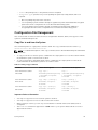
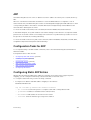
Configuration File Management.........................................................................................................47
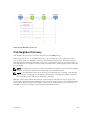
Copy Files to and from the System.............................................................................................. 47
Save the Running-Configuration..................................................................................................48
Configure the Overload Bit for a Startup Scenario......................................................................49
Viewing Files.................................................................................................................................. 49
Managing the File System................................................................................................................... 50
View Command History...................................................................................................................... 51
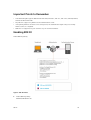
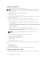
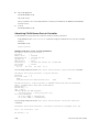
Upgrading Dell Networking OS...........................................................................................................51
Using HTTP for File Transfers..............................................................................................................51
Using Hashes to Validate Software Images........................................................................................52
4 Management....................................................................................................... 54
Configuring Privilege Levels............................................................................................................... 54
Creating a Custom Privilege Level................................................................................................54
Removing a Command from EXEC Mode................................................................................... 54
Moving a Command from EXEC Privilege Mode to EXEC Mode................................................ 54
Allowing Access to CONFIGURATION Mode Commands.......................................................... 55
Allowing Access to the Following Modes.....................................................................................55
Applying a Privilege Level to a Username.....................................................................................57
Applying a Privilege Level to a Terminal Line............................................................................... 57
Configuring Logging........................................................................................................................... 57
Audit and Security Logs.................................................................................................................58
Configuring Logging Format ...................................................................................................... 59
Setting Up a Secure Connection to a Syslog Server....................................................................60
Log Messages in the Internal Buffer................................................................................................... 61
Configuration Task List for System Log Management................................................................. 61
Disabling System Logging................................................................................................................... 61
Sending System Messages to a Syslog Server....................................................................................62
Configuring a UNIX System as a Syslog Server............................................................................ 62
Changing System Logging Settings....................................................................................................62
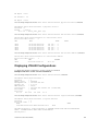
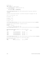
Display the Logging Buffer and the Logging Configuration............................................................. 63
Configuring a UNIX Logging Facility Level.........................................................................................64
Synchronizing Log Messages............................................................................................................. 65
Enabling Timestamp on Syslog Messages......................................................................................... 65
File Transfer Services.......................................................................................................................... 66
Configuration Task List for File Transfer Services........................................................................66
Enabling the FTP Server................................................................................................................ 66
Configuring FTP Server Parameters..............................................................................................67
Configuring FTP Client Parameters.............................................................................................. 67
Terminal Lines..................................................................................................................................... 68
Denying and Permitting Access to a Terminal Line.....................................................................68
Configuring Login Authentication for Terminal Lines................................................................. 69
Setting Time Out of EXEC Privilege Mode......................................................................................... 70
Using Telnet to get to Another Network Device............................................................................... 70
Lock CONFIGURATION Mode............................................................................................................ 71
Viewing the Configuration Lock Status.........................................................................................71
Restoring the Factory Default Settings...............................................................................................72
S6000MXL Switch..........................................................................................................................72
Important Points to Remember.................................................................................................... 72
Restoring Factory Default Environment Variables....................................................................... 73
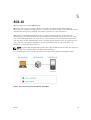
5 802.1X................................................................................................................... 75
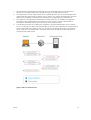
The Port-Authentication Process....................................................................................................... 76
EAP over RADIUS........................................................................................................................... 78
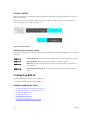
Configuring 802.1X............................................................................................................................. 78
Related Configuration Tasks......................................................................................................... 78
Important Points to Remember..........................................................................................................79
Enabling 802.1X...................................................................................................................................79
Configuring Request Identity Re-Transmissions................................................................................81
Configuring a Quiet Period after a Failed Authentication............................................................81
Forcibly Authorizing or Unauthorizing a Port.................................................................................... 82
Re-Authenticating a Port.................................................................................................................... 83
Configuring Timeouts.........................................................................................................................84
Configuring Dynamic VLAN Assignment with Port Authentication..................................................85
Guest and Authentication-Fail VLANs................................................................................................86
Configuring a Guest VLAN............................................................................................................ 87
Configuring an Authentication-Fail VLAN.................................................................................... 87
6 Access Control Lists (ACLs).............................................................................. 89
IP Access Control Lists (ACLs)............................................................................................................ 90
CAM Usage.................................................................................................................................... 90
Implementing ACLs on Dell Networking OS................................................................................92
Important Points to Remember..........................................................................................................93
Configuration Task List for Route Maps....................................................................................... 93
Configuring Match Routes............................................................................................................96
Configuring Set Conditions...........................................................................................................97
Configure a Route Map for Route Redistribution........................................................................ 98
Configure a Route Map for Route Tagging..................................................................................99
Continue Clause............................................................................................................................99
IP Fragment Handling....................................................................................................................... 100
IP Fragments ACL Examples....................................................................................................... 100
Layer 4 ACL Rules Examples....................................................................................................... 101
Configure a Standard IP ACL............................................................................................................ 102
Configuring a Standard IP ACL Filter.......................................................................................... 103
Configure an Extended IP ACL......................................................................................................... 104
Configuring Filters with a Sequence Number............................................................................104
Configuring Filters Without a Sequence Number......................................................................105
Configure Layer 2 and Layer 3 ACLs................................................................................................ 106
Assign an IP ACL to an Interface.......................................................................................................107
Applying an IP ACL............................................................................................................................ 107
Counting ACL Hits.......................................................................................................................108
Configure Ingress ACLs.................................................................................................................... 108
Configure Egress ACLs..................................................................................................................... 109
Applying Egress Layer 3 ACLs (Control-Plane)...........................................................................110
IP Prefix Lists...................................................................................................................................... 110
Implementation Information....................................................................................................... 111
Configuration Task List for Prefix Lists........................................................................................ 111
ACL Resequencing.............................................................................................................................115
Resequencing an ACL or Prefix List............................................................................................ 115
Route Maps........................................................................................................................................ 117
Implementation Information....................................................................................................... 117
Flow-Based Monitoring Support for ACLs........................................................................................117
Behavior of Flow-Based Monitoring........................................................................................... 118
Enabling Flow-Based Monitoring................................................................................................119
7 Bidirectional Forwarding Detection (BFD)................................................... 121
How BFD Works.................................................................................................................................121
BFD Packet Format......................................................................................................................122
BFD Sessions................................................................................................................................124
BFD Three-Way Handshake........................................................................................................124
Session State Changes................................................................................................................ 125
Important Points to Remember........................................................................................................126
Configure BFD...................................................................................................................................126
Configure BFD for Physical Ports................................................................................................127
Configure BFD for Static Routes.................................................................................................130
Configure BFD for OSPF............................................................................................................. 132
Configure BFD for OSPFv3..........................................................................................................135
Configure BFD for IS-IS...............................................................................................................136
Configure BFD for BGP............................................................................................................... 139
Configure BFD for VRRP............................................................................................................. 146
Configuring Protocol Liveness................................................................................................... 149
Troubleshooting BFD.................................................................................................................. 149
8 Border Gateway Protocol IPv4 (BGPv4)....................................................... 151
Autonomous Systems (AS)................................................................................................................ 151
Sessions and Peers............................................................................................................................ 153
Establish a Session.......................................................................................................................154
Route Reflectors................................................................................................................................154
BGP Attributes................................................................................................................................... 155
Best Path Selection Criteria.........................................................................................................156
Weight..........................................................................................................................................158
Local Preference......................................................................................................................... 158
Multi-Exit Discriminators (MEDs)................................................................................................ 159
Origin........................................................................................................................................... 160
AS Path......................................................................................................................................... 161
Next Hop...................................................................................................................................... 161
Multiprotocol BGP.............................................................................................................................162
Implement BGP with Dell Networking OS....................................................................................... 162
Additional Path (Add-Path) Support........................................................................................... 162
Advertise IGP Cost as MED for Redistributed Routes................................................................ 162
Ignore Router-ID for Some Best-Path Calculations.................................................................. 163
Four-Byte AS Numbers............................................................................................................... 163
AS4 Number Representation...................................................................................................... 164
AS Number Migration.................................................................................................................. 165
BGP4 Management Information Base (MIB)...............................................................................167
Important Points to Remember.................................................................................................. 167
Configuration Information................................................................................................................168
BGP Configuration............................................................................................................................ 168
Enabling BGP............................................................................................................................... 169
Configuring AS4 Number Representations................................................................................ 173
Configuring Peer Groups............................................................................................................ 175
Configuring BGP Fast Fall-Over.................................................................................................. 177
Configuring Passive Peering....................................................................................................... 179
Maintaining Existing AS Numbers During an AS Migration........................................................180
Allowing an AS Number to Appear in its Own AS Path.............................................................. 181
Enabling Graceful Restart............................................................................................................182
Enabling Neighbor Graceful Restart........................................................................................... 183
Filtering on an AS-Path Attribute................................................................................................ 183
Regular Expressions as Filters..................................................................................................... 185
Redistributing Routes.................................................................................................................. 186
Enabling Additional Paths............................................................................................................187
Configuring IP Community Lists.................................................................................................187
Configuring an IP Extended Community List.............................................................................189
Filtering Routes with Community Lists...................................................................................... 190
Manipulating the COMMUNITY Attribute...................................................................................190
Changing MED Attributes............................................................................................................192
Changing the LOCAL_PREFERENCE Attribute...........................................................................192
Changing the NEXT_HOP Attribute............................................................................................193
Changing the WEIGHT Attribute.................................................................................................194
Enabling Multipath...................................................................................................................... 194
Filtering BGP Routes................................................................................................................... 194
Filtering BGP Routes Using Route Maps.................................................................................... 196
Filtering BGP Routes Using AS-PATH Information.................................................................... 197
Configuring BGP Route Reflectors............................................................................................. 197
Aggregating Routes.....................................................................................................................198
Configuring BGP Confederations...............................................................................................199
Enabling Route Flap Dampening................................................................................................ 199
Changing BGP Timers................................................................................................................ 202
Enabling BGP Neighbor Soft-Reconfiguration..........................................................................202
Route Map Continue.................................................................................................................. 204
Enabling MBGP Configurations....................................................................................................... 204
BGP Regular Expression Optimization.............................................................................................205
Debugging BGP................................................................................................................................ 205
Storing Last and Bad PDUs.........................................................................................................206
Capturing PDUs...........................................................................................................................207
PDU Counters............................................................................................................................. 208
Sample Configurations.....................................................................................................................209
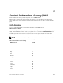
9 Content Addressable Memory (CAM)........................................................... 215
CAM Allocation..................................................................................................................................215
Test CAM Usage................................................................................................................................ 217
View CAM Profiles............................................................................................................................. 217
View CAM-ACL Settings....................................................................................................................218
View CAM Usage...............................................................................................................................220
CAM Optimization............................................................................................................................ 220
Troubleshoot CAM Profiling............................................................................................................. 221
CAM Profile Mismatches............................................................................................................. 221
QoS CAM Region Limitation....................................................................................................... 221
Syslog Error When the Table is Full............................................................................................ 221
Syslog Warning Upon 90 Percent Utilization of CAM............................................................... 222
Syslog Warning for Discrepancies Between Configured Extended Prefixes............................ 222
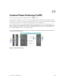
10 Control Plane Policing (CoPP)..................................................................... 223
Configure Control Plane Policing.................................................................................................... 224
Configuring CoPP for Protocols.................................................................................................225
Configuring CoPP for CPU Queues........................................................................................... 227
Show Commands....................................................................................................................... 228
11 Data Center Bridging (DCB)..........................................................................230
Ethernet Enhancements in Data Center Bridging........................................................................... 230
Priority-Based Flow Control....................................................................................................... 231
Enhanced Transmission Selection..............................................................................................233
Data Center Bridging Exchange Protocol (DCBx)..................................................................... 235
Data Center Bridging in a Traffic Flow....................................................................................... 235
Enabling Data Center Bridging.........................................................................................................236
QoS dot1p Traffic Classification and Queue Assignment............................................................... 236
SNMP Support for PFC and Buffer Statistics Tracking.....................................................................237
Configuring Priority-Based Flow Control........................................................................................ 238
Configuring Lossless Queues.....................................................................................................240
Configuring the PFC Buffer in a Switch Stack............................................................................241
Configure Enhanced Transmission Selection..................................................................................242
ETS Prerequisites and Restrictions............................................................................................. 242
Creating a QoS DCB Output Policy........................................................................................... 243
Creating an ETS Priority Group.................................................................................................. 245
Applying an ETS Output Policy for a Priority Group to an Interface........................................ 246
ETS Operation with DCBx...........................................................................................................247
Configuring Bandwidth Allocation for DCBx CIN..................................................................... 248
Applying DCB Policies in a Switch Stack......................................................................................... 248
Applying DCB Policies with an ETS Configuration..........................................................................249
Configure a DCBx Operation........................................................................................................... 249
DCBx Operation..........................................................................................................................250
DCBx Port Roles..........................................................................................................................250
DCB Configuration Exchange.................................................................................................... 252
Configuration Source Election................................................................................................... 252
Propagation of DCB Information............................................................................................... 253
Auto-Detection and Manual Configuration of the DCBx Version............................................ 253
Behavior of Tagged Packets....................................................................................................... 254
Configuration Example for DSCP and PFC Priorities.................................................................254
DCBx Example.............................................................................................................................255
DCBx Prerequisites and Restrictions.......................................................................................... 256
Configuring DCBx....................................................................................................................... 256
Verifying the DCB Configuration..................................................................................................... 260
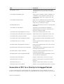
Generation of PFC for a Priority for Untagged Packets...................................................................271
Operations on Untagged Packets.................................................................................................... 272
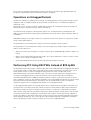
Performing PFC Using DSCP Bits Instead of 802.1p Bits.................................................................272
PFC and ETS Configuration Examples............................................................................................. 273
Using PFC and ETS to Manage Data Center Traffic.........................................................................273
PFC and ETS Configuration Command Examples.....................................................................275
Using PFC and ETS to Manage Converged Ethernet Traffic in a Switch Stack........................ 276
Hierarchical Scheduling in ETS Output Policies........................................................................ 276
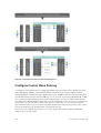
Configuring DCB Maps and its Attributes.........................................................................................277
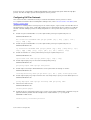
DCB Map: Configuration Procedure.......................................................................................... 277
Important Points to Remember..................................................................................................278
Applying a DCB Map on a Port................................................................................................... 278
Configuring PFC without a DCB Map........................................................................................ 279
Configuring Lossless Queues.....................................................................................................280
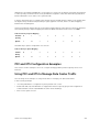
Data Center Bridging: Default Configuration.................................................................................. 281
Configuring PFC and ETS in a DCB Map.......................................................................................... 281
PFC Configuration Notes............................................................................................................ 281
PFC Prerequisites and Restrictions.............................................................................................282
ETS Configuration Notes............................................................................................................ 283
ETS Prerequisites and Restrictions............................................................................................. 283
Priority-Based Flow Control Using Dynamic Buffer Method..........................................................284
Pause and Resume of Traffic......................................................................................................284
Buffer Sizes for Lossless or PFC Packets....................................................................................285
Interworking of DCB Map With DCB Buffer Threshold Settings.....................................................285
Configuring the Dynamic Buffer Method........................................................................................ 286
Applying a DCB Map in a Switch Stack ........................................................................................... 288
12 Dynamic Host Configuration Protocol (DHCP)........................................289
DHCP Packet Format and Options.................................................................................................. 289
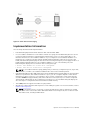
Assign an IP Address using DHCP.................................................................................................... 291
Implementation Information............................................................................................................292
Configure the System to be a DHCP Server.................................................................................... 293
Configuring the Server for Automatic Address Allocation........................................................ 293
Specifying a Default Gateway.....................................................................................................295
Configure a Method of Hostname Resolution.......................................................................... 295
Using DNS for Address Resolution............................................................................................. 295
Using NetBIOS WINS for Address Resolution............................................................................ 295
Creating Manual Binding Entries................................................................................................ 296
Debugging the DHCP Server......................................................................................................296
Using DHCP Clear Commands.................................................................................................. 296
Configure the System to be a DHCP Client.....................................................................................297
Configuring the DHCP Client System........................................................................................ 297
DHCP Client on a Management Interface................................................................................. 299
DHCP Client Operation with Other Features............................................................................ 299
Configure the System for User Port Stacking (Option 230)........................................................... 300
Configure Secure DHCP................................................................................................................... 301
Option 82.....................................................................................................................................301
DHCP Snooping..........................................................................................................................302
Drop DHCP Packets on Snooped VLANs Only..........................................................................304
Dynamic ARP Inspection............................................................................................................ 304
Configuring Dynamic ARP Inspection....................................................................................... 305
Source Address Validation................................................................................................................306
Enabling IP Source Address Validation...................................................................................... 306
DHCP MAC Source Address Validation......................................................................................307
Enabling IP+MAC Source Address Validation............................................................................ 307
13 Equal Cost Multi-Path (ECMP)..................................................................... 309
ECMP for Flow-Based Affinity..........................................................................................................309
Configuring the Hash Algorithm................................................................................................ 309
Enabling Deterministic ECMP Next Hop....................................................................................309
Configuring the Hash Algorithm Seed....................................................................................... 310
Link Bundle Monitoring.....................................................................................................................310
Managing ECMP Group Paths..................................................................................................... 311
Creating an ECMP Group Bundle............................................................................................... 312
Modifying the ECMP Group Threshold.......................................................................................312
Support for /128 IPv6 and /32 IPv4 Prefixes in Layer 3 Host Table and LPM Table................. 313
Support for ECMP in host table.................................................................................................. 313
Support for moving /128 IPv6 Prefixes and /32 IPv4 Prefixes .................................................. 314
14 FCoE Transit.....................................................................................................315
Fibre Channel over Ethernet............................................................................................................. 315
Ensure Robustness in a Converged Ethernet Network................................................................... 315
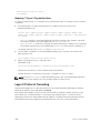
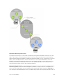
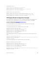
FIP Snooping on Ethernet Bridges....................................................................................................317
FIP Snooping in a Switch Stack.........................................................................................................319
Using FIP Snooping........................................................................................................................... 319
FIP Snooping Prerequisites......................................................................................................... 319
Important Points to Remember................................................................................................. 320
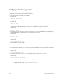
Enabling the FCoE Transit Feature............................................................................................. 320
Enable FIP Snooping on VLANs.................................................................................................. 321
Configure the FC-MAP Value......................................................................................................321
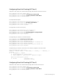
Configure a Port for a Bridge-to-Bridge Link............................................................................ 321
Configure a Port for a Bridge-to-FCF Link.................................................................................321
Impact on Other Software Features........................................................................................... 321
FIP Snooping Restrictions........................................................................................................... 322
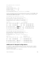
Configuring FIP Snooping...........................................................................................................322
Displaying FIP Snooping Information...............................................................................................323
FCoE Transit Configuration Example...............................................................................................329
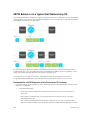
15 Flex Hash and Optimized Boot-Up..............................................................331
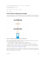
Flex Hash Capability Overview..........................................................................................................331
Configuring the Flex Hash Mechanism............................................................................................ 331
Configuring Fast Boot and LACP Fast Switchover...........................................................................332
Optimizing the Boot Time................................................................................................................ 332
Booting Process When Optimized Boot Time Mechanism is Enabled.....................................333
Guidelines for Configuring Optimized Booting Mechanism.....................................................333
Interoperation of Applications with Fast Boot and System States..................................................334
LACP and IPv4 Routing...............................................................................................................334
LACP and IPv6 Routing............................................................................................................... 335
BGP Graceful Restart.................................................................................................................. 335
Cold Boot Caused by Power Cycling the System..................................................................... 335
Unexpected Reload of the System............................................................................................. 335
Software Upgrade....................................................................................................................... 336
LACP Fast Switchover................................................................................................................. 336
Changes to BGP Multipath......................................................................................................... 336
Delayed Installation of ECMP Routes Into BGP.........................................................................336
RDMA Over Converged Ethernet (RoCE) Overview........................................................................ 337
Preserving 802.1Q VLAN Tag Value for Lite Subinterfaces............................................................. 338
16 Force10 Resilient Ring Protocol (FRRP)..................................................... 339
Protocol Overview............................................................................................................................ 339
Ring Status.................................................................................................................................. 340
Multiple FRRP Rings.....................................................................................................................341
Important FRRP Points................................................................................................................ 341
Important FRRP Concepts.......................................................................................................... 341
Implementing FRRP.......................................................................................................................... 343
FRRP Configuration.......................................................................................................................... 343
Creating the FRRP Group........................................................................................................... 343
Configuring the Control VLAN................................................................................................... 344
Configuring and Adding the Member VLANs.............................................................................345
Setting the FRRP Timers............................................................................................................. 346
Clearing the FRRP Counters....................................................................................................... 347
Viewing the FRRP Configuration................................................................................................ 347
Viewing the FRRP Information....................................................................................................347
Troubleshooting FRRP......................................................................................................................348
Configuration Checks.................................................................................................................348
Sample Configuration and Topology.............................................................................................. 348
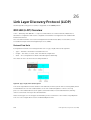
17 GARP VLAN Registration Protocol (GVRP)................................................ 350
Important Points to Remember....................................................................................................... 350
Configure GVRP................................................................................................................................ 351
Related Configuration Tasks....................................................................................................... 351
Enabling GVRP Globally....................................................................................................................352
Enabling GVRP on a Layer 2 Interface............................................................................................. 352
Configure GVRP Registration........................................................................................................... 352
Configure a GARP Timer...................................................................................................................353
18 Internet Group Management Protocol (IGMP)......................................... 355
IGMP Implementation Information.................................................................................................. 355
IGMP Protocol Overview.................................................................................................................. 355
IGMP Version 2............................................................................................................................355
IGMP Version 3............................................................................................................................ 357
Configure IGMP................................................................................................................................ 360
Related Configuration Tasks...................................................................................................... 360
Viewing IGMP Enabled Interfaces.....................................................................................................361
Selecting an IGMP Version................................................................................................................361
Viewing IGMP Groups.......................................................................................................................362
Adjusting Timers............................................................................................................................... 362
Adjusting Query and Response Timers...................................................................................... 362
Adjusting the IGMP Querier Timeout Value...............................................................................363
Configuring a Static IGMP Group.....................................................................................................363
Enabling IGMP Immediate-Leave.................................................................................................... 364
IGMP Snooping................................................................................................................................. 364
IGMP Snooping Implementation Information........................................................................... 364
Configuring IGMP Snooping...................................................................................................... 364
Removing a Group-Port Association......................................................................................... 365
Disabling Multicast Flooding...................................................................................................... 365
Specifying a Port as Connected to a Multicast Router..............................................................366
Configuring the Switch as Querier.............................................................................................366
Fast Convergence after MSTP Topology Changes..........................................................................367
Egress Interface Selection (EIS) for HTTP and IGMP Applications..................................................367
Protocol Separation.................................................................................................................... 368
Enabling and Disabling Management Egress Interface Selection.............................................369
Handling of Management Route Configuration........................................................................ 370
Handling of Switch-Initiated Traffic........................................................................................... 370
Handling of Switch-Destined Traffic.......................................................................................... 371
Handling of Transit Traffic (Traffic Separation).......................................................................... 372
Mapping of Management Applications and Traffic Type...........................................................372
Behavior of Various Applications for Switch-Initiated Traffic ...................................................373
Behavior of Various Applications for Switch-Destined Traffic ................................................. 374
Interworking of EIS With Various Applications...........................................................................375
Designating a Multicast Router Interface.........................................................................................376
19 Interfaces......................................................................................................... 377
Basic Interface Configuration........................................................................................................... 377
Advanced Interface Configuration................................................................................................... 377
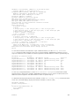
Interface Types..................................................................................................................................378
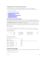
View Basic Interface Information..................................................................................................... 378
Enabling a Physical Interface........................................................................................................... 380
Physical Interfaces............................................................................................................................ 380
Configuration Task List for Physical Interfaces.......................................................................... 381
40G to 1G Breakout Cable Adaptor............................................................................................381
Overview of Layer Modes........................................................................................................... 381
Configuring Layer 2 (Data Link) Mode....................................................................................... 382
Configuring Layer 2 (Interface) Mode........................................................................................ 382
Configuring Layer 3 (Network) Mode.........................................................................................383
Configuring Layer 3 (Interface) Mode........................................................................................ 383
Egress Interface Selection (EIS)........................................................................................................384
Important Points to Remember................................................................................................. 384
Configuring EIS........................................................................................................................... 385
Management Interfaces....................................................................................................................385
Configuring Management Interfaces......................................................................................... 385
Configuring Management Interfaces on the S-Series...............................................................386
VLAN Interfaces................................................................................................................................ 386
Loopback Interfaces......................................................................................................................... 387
Null Interfaces...................................................................................................................................388
Port Channel Interfaces....................................................................................................................388
Port Channel Definition and Standards..................................................................................... 388
Port Channel Benefits.................................................................................................................389
Port Channel Implementation....................................................................................................389
10/100/1000 Mbps Interfaces in Port Channels........................................................................389
Configuration Tasks for Port Channel Interfaces......................................................................390
Creating a Port Channel............................................................................................................. 390
Adding a Physical Interface to a Port Channel...........................................................................391
Reassigning an Interface to a New Port Channel......................................................................393
Configuring the Minimum Oper Up Links in a Port Channel.................................................... 393
..................................................................................................................................................... 394
Assigning an IP Address to a Port Channel................................................................................394
Deleting or Disabling a Port Channel.........................................................................................395
Load Balancing Through Port Channels.................................................................................... 395
Load-Balancing on the S- Series................................................................................................395
Changing the Hash Algorithm....................................................................................................396
Bulk Configuration............................................................................................................................ 397
Interface Range........................................................................................................................... 397
Bulk Configuration Examples..................................................................................................... 398
Defining Interface Range Macros.................................................................................................... 399
Define the Interface Range.........................................................................................................399
Choosing an Interface-Range Macro........................................................................................ 400
Monitoring and Maintaining Interfaces........................................................................................... 400
Maintenance Using TDR............................................................................................................. 401
Splitting QSFP Ports to SFP+ Ports.................................................................................................. 402
Converting a QSFP or QSFP+ Port to an SFP or SFP+ Port............................................................402
Important Points to Remember................................................................................................. 403
Support for LM4 Optics.............................................................................................................. 404
Example Scenarios......................................................................................................................404
Link Dampening............................................................................................................................... 408
Important Points to Remember................................................................................................. 408
Enabling Link Dampening.......................................................................................................... 408
Link Bundle Monitoring.....................................................................................................................410
Using Ethernet Pause Frames for Flow Control.............................................................................. 410
Threshold Settings....................................................................................................................... 411
Enabling Pause Frames................................................................................................................411
Configure the MTU Size on an Interface..........................................................................................412
Port-Pipes..........................................................................................................................................413
Auto-Negotiation on Ethernet Interfaces........................................................................................ 413
Setting the Speed and Duplex Mode of Ethernet Interfaces..................................................... 414
Set Auto-Negotiation Options....................................................................................................415
View Advanced Interface Information..............................................................................................416
Configuring the Interface Sampling Size....................................................................................417
Dynamic Counters............................................................................................................................ 418
Clearing Interface Counters....................................................................................................... 418
Enhanced Validation of Interface Ranges........................................................................................ 419
Compressing Configuration Files..................................................................................................... 419
20 IPv4 Routing................................................................................................... 423
IP Addresses...................................................................................................................................... 423
Implementation Information...................................................................................................... 423
Configuration Tasks for IP Addresses.............................................................................................. 423
Assigning IP Addresses to an Interface............................................................................................ 424
Configuring Static Routes.................................................................................................................425
Configure Static Routes for the Management Interface.................................................................426
Using the Configured Source IP Address in ICMP Messages..........................................................427
Configuring the ICMP Source Interface.....................................................................................427
Configuring the Duration to Establish a TCP Connection.............................................................. 427
Enabling Directed Broadcast............................................................................................................428
Resolution of Host Names............................................................................................................... 428
Enabling Dynamic Resolution of Host Names................................................................................ 429
Specifying the Local System Domain and a List of Domains..........................................................429
Configuring DNS with Traceroute................................................................................................... 430
ARP.....................................................................................................................................................431
Configuration Tasks for ARP.............................................................................................................431
Configuring Static ARP Entries..........................................................................................................431
Enabling Proxy ARP...........................................................................................................................432
Clearing ARP Cache..........................................................................................................................432
ARP Learning via Gratuitous ARP..................................................................................................... 433
Enabling ARP Learning via Gratuitous ARP...................................................................................... 433
ARP Learning via ARP Request......................................................................................................... 433
Configuring ARP Retries................................................................................................................... 434
ICMP.................................................................................................................................................. 435
Configuration Tasks for ICMP.......................................................................................................... 435
Enabling ICMP Unreachable Messages............................................................................................435
UDP Helper....................................................................................................................................... 436
Configure UDP Helper................................................................................................................436
Important Points to Remember................................................................................................. 436
Enabling UDP Helper........................................................................................................................ 436
Configuring a Broadcast Address.....................................................................................................437
Configurations Using UDP Helper....................................................................................................437
UDP Helper with Broadcast-All Addresses...................................................................................... 437
UDP Helper with Subnet Broadcast Addresses............................................................................... 438
UDP Helper with Configured Broadcast Addresses........................................................................ 439
UDP Helper with No Configured Broadcast Addresses.................................................................. 439
Troubleshooting UDP Helper.......................................................................................................... 440
21 IPv6 Routing.................................................................................................... 441
Protocol Overview............................................................................................................................ 441
Extended Address Space.............................................................................................................441
Stateless Autoconfiguration........................................................................................................441
IPv6 Headers............................................................................................................................... 442
Longest Prefix Match (LPM) Table and IPv6 /65 – /128 support.............................................. 442
IPv6 Header Fields...................................................................................................................... 444
Extension Header Fields............................................................................................................. 445
Addressing...................................................................................................................................446
Implementing IPv6 with Dell Networking OS................................................................................. 448
ICMPv6..............................................................................................................................................450
Path MTU Discovery......................................................................................................................... 450
IPv6 Neighbor Discovery.................................................................................................................. 451
IPv6 Neighbor Discovery of MTU Packets................................................................................. 452
Configuring the IPv6 Recursive DNS Server.............................................................................. 452
Debugging IPv6 RDNSS Information Sent to the Host .............................................................453
Displaying IPv6 RDNSS Information...........................................................................................453
Secure Shell (SSH) Over an IPv6 Transport......................................................................................454
Configuration Tasks for IPv6............................................................................................................ 454
Adjusting Your CAM-Profile........................................................................................................455
Assigning an IPv6 Address to an Interface................................................................................. 455
Assigning a Static IPv6 Route..................................................................................................... 456
Configuring Telnet with IPv6...................................................................................................... 457
SNMP over IPv6........................................................................................................................... 457
Showing IPv6 Information.......................................................................................................... 457
Showing an IPv6 Interface..........................................................................................................458
Showing IPv6 Routes.................................................................................................................. 459
Showing the Running-Configuration for an Interface..............................................................460
Clearing IPv6 Routes.................................................................................................................. 460
22 iSCSI Optimization.........................................................................................462
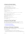
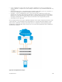
iSCSI Optimization Overview........................................................................................................... 462
Monitoring iSCSI Traffic Flows................................................................................................... 464
Application of Quality of Service to iSCSI Traffic Flows............................................................464
Information Monitored in iSCSI Traffic Flows............................................................................464
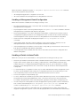
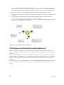
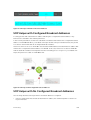
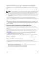
Detection and Auto-Configuration for Dell EqualLogic Arrays................................................ 465
Configuring Detection and Ports for Dell Compellent Arrays.................................................. 466
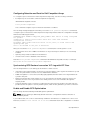
Synchronizing iSCSI Sessions Learned on VLT-Lags with VLT-Peer........................................466
Enable and Disable iSCSI Optimization..................................................................................... 466
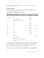
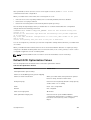
Default iSCSI Optimization Values................................................................................................... 467
iSCSI Optimization Prerequisites..................................................................................................... 468
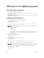
Configuring iSCSI Optimization.......................................................................................................468
Displaying iSCSI Optimization Information..................................................................................... 470
23 Intermediate System to Intermediate System.......................................... 472
IS-IS Protocol Overview................................................................................................................... 472
IS-IS Addressing................................................................................................................................ 472
Multi-Topology IS-IS.........................................................................................................................473
Transition Mode.......................................................................................................................... 474
Interface Support........................................................................................................................ 474
Adjacencies................................................................................................................................. 474
Graceful Restart................................................................................................................................ 474
Timers.......................................................................................................................................... 475
Implementation Information............................................................................................................ 475
Configuration Information............................................................................................................... 476
Configuration Tasks for IS-IS......................................................................................................476
Configuring the Distance of a Route......................................................................................... 485
Changing the IS-Type.................................................................................................................485
Redistributing IPv4 Routes......................................................................................................... 488
Redistributing IPv6 Routes......................................................................................................... 489
Configuring Authentication Passwords..................................................................................... 490
Setting the Overload Bit............................................................................................................. 490
Debugging IS-IS.......................................................................................................................... 491
IS-IS Metric Styles............................................................................................................................. 492
Configure Metric Values................................................................................................................... 492
Maximum Values in the Routing Table...................................................................................... 493
Change the IS-IS Metric Style in One Level Only...................................................................... 493
Leaks from One Level to Another.............................................................................................. 495
Sample Configurations..................................................................................................................... 495
24 Link Aggregation Control Protocol (LACP).............................................. 498
Introduction to Dynamic LAGs and LACP....................................................................................... 498
Important Points to Remember................................................................................................. 498
LACP Modes................................................................................................................................499
Configuring LACP Commands...................................................................................................499
LACP Configuration Tasks................................................................................................................500
Creating a LAG............................................................................................................................500
Configuring the LAG Interfaces as Dynamic..............................................................................501
Setting the LACP Long Timeout................................................................................................. 501
Monitoring and Debugging LACP.............................................................................................. 502
Shared LAG State Tracking............................................................................................................... 502
Configuring Shared LAG State Tracking.................................................................................... 503
Important Points about Shared LAG State Tracking..................................................................504
LACP Basic Configuration Example................................................................................................. 505
Configure a LAG on ALPHA........................................................................................................ 505
25 Layer 2...............................................................................................................513
Manage the MAC Address Table.......................................................................................................513
Clearing the MAC Address Table................................................................................................ 513
Setting the Aging Time for Dynamic Entries.............................................................................. 513
Configuring a Static MAC Address..............................................................................................514
Displaying the MAC Address Table............................................................................................. 514
MAC Learning Limit........................................................................................................................... 514
Setting the MAC Learning Limit.................................................................................................. 515
mac learning-limit Dynamic....................................................................................................... 515
mac learning-limit mac-address-sticky..................................................................................... 516
mac learning-limit station-move................................................................................................516
mac learning-limit no-station-move......................................................................................... 516
Learning Limit Violation Actions................................................................................................. 517
Setting Station Move Violation Actions.......................................................................................517
Recovering from Learning Limit and Station Move Violations.................................................. 518
NIC Teaming..................................................................................................................................... 518
Configure Redundant Pairs...............................................................................................................519
Important Points about Configuring Redundant Pairs...............................................................521
Far-End Failure Detection.................................................................................................................522
FEFD State Changes....................................................................................................................523
Configuring FEFD........................................................................................................................524
Enabling FEFD on an Interface................................................................................................... 525
Debugging FEFD......................................................................................................................... 526
26 Link Layer Discovery Protocol (LLDP)........................................................ 528
802.1AB (LLDP) Overview................................................................................................................. 528
Protocol Data Units.....................................................................................................................528
Optional TLVs....................................................................................................................................529
Management TLVs...................................................................................................................... 529
TIA-1057 (LLDP-MED) Overview...................................................................................................... 531
TIA Organizationally Specific TLVs............................................................................................. 532
Configure LLDP.................................................................................................................................536
Related Configuration Tasks.......................................................................................................536
Important Points to Remember..................................................................................................537
LLDP Compatibility......................................................................................................................537
CONFIGURATION versus INTERFACE Configurations.................................................................... 537
Enabling LLDP................................................................................................................................... 538
Disabling and Undoing LLDP......................................................................................................538
Enabling LLDP on Management Ports............................................................................................. 538
Disabling and Undoing LLDP on Management Ports................................................................ 538
Advertising TLVs................................................................................................................................539
Viewing the LLDP Configuration......................................................................................................540
Viewing Information Advertised by Adjacent LLDP Agents............................................................. 541
Configuring LLDPDU Intervals......................................................................................................... 542
Configuring Transmit and Receive Mode........................................................................................ 542
Configuring a Time to Live............................................................................................................... 543
Debugging LLDP...............................................................................................................................544
Relevant Management Objects........................................................................................................ 545
27 Microsoft Network Load Balancing............................................................ 551
NLB Unicast Mode Scenario............................................................................................................. 551
NLB Multicast Mode Scenario.......................................................................................................... 552
Limitations With Enabling NLB on Switches.................................................................................... 552
Benefits and Working of Microsoft Clustering.................................................................................552
Enable and Disable VLAN Flooding ................................................................................................. 553
Configuring a Switch for NLB ..........................................................................................................553
..................................................................................................................................................... 553
28 Multicast Source Discovery Protocol (MSDP)...........................................554
Protocol Overview............................................................................................................................ 554
Anycast RP.........................................................................................................................................556
Implementation Information............................................................................................................ 556
Configure Multicast Source Discovery Protocol............................................................................. 556
Related Configuration Tasks.......................................................................................................556
Enable MSDP.....................................................................................................................................560
Manage the Source-Active Cache....................................................................................................561
Viewing the Source-Active Cache..............................................................................................561
Limiting the Source-Active Cache............................................................................................. 562
Clearing the Source-Active Cache.............................................................................................562
Enabling the Rejected Source-Active Cache.............................................................................562
Accept Source-Active Messages that Fail the RFP Check...............................................................562
Specifying Source-Active Messages................................................................................................ 566
Limiting the Source-Active Messages from a Peer..........................................................................567
Preventing MSDP from Caching a Local Source............................................................................. 567
Preventing MSDP from Caching a Remote Source.........................................................................568
Preventing MSDP from Advertising a Local Source........................................................................ 569
Logging Changes in Peership States................................................................................................570
Terminating a Peership.....................................................................................................................570
Clearing Peer Statistics..................................................................................................................... 570
Debugging MSDP.............................................................................................................................. 571
MSDP with Anycast RP...................................................................................................................... 571
Configuring Anycast RP.................................................................................................................... 573
Reducing Source-Active Message Flooding.............................................................................. 573
Specifying the RP Address Used in SA Messages....................................................................... 573
MSDP Sample Configurations.......................................................................................................... 576
29 Multiple Spanning Tree Protocol (MSTP).................................................. 579
Protocol Overview............................................................................................................................ 579
Spanning Tree Variations..................................................................................................................580
Implementation Information......................................................................................................580
Configure Multiple Spanning Tree Protocol....................................................................................580
Related Configuration Tasks...................................................................................................... 580
Enable Multiple Spanning Tree Globally.......................................................................................... 581
Adding and Removing Interfaces..................................................................................................... 581
Creating Multiple Spanning Tree Instances..................................................................................... 581
Influencing MSTP Root Selection.....................................................................................................583
Interoperate with Non-Dell Networking OS Bridges...................................................................... 583
Changing the Region Name or Revision......................................................................................... 584
Modifying Global Parameters...........................................................................................................584
Modifying the Interface Parameters.................................................................................................585
Configuring an EdgePort..................................................................................................................586
Flush MAC Addresses after a Topology Change............................................................................. 587
MSTP Sample Configurations...........................................................................................................587
Router 1 Running-ConfigurationRouter 2 Running-ConfigurationRouter 3 RunningConfigurationSFTOS Example Running-Configuration............................................................ 588
Debugging and Verifying MSTP Configurations.............................................................................. 591
30 Multicast Features..........................................................................................594
Enabling IP Multicast........................................................................................................................ 594
Multicast with ECMP.........................................................................................................................594
Implementation Information............................................................................................................ 595
First Packet Forwarding for Lossless Multicast................................................................................ 596
Multicast Policies.............................................................................................................................. 596
IPv4 Multicast Policies................................................................................................................ 596
31 Open Shortest Path First (OSPFv2 and OSPFv3).......................................605
Protocol Overview............................................................................................................................605
Autonomous System (AS) Areas................................................................................................. 605
Area Types...................................................................................................................................606
Networks and Neighbors............................................................................................................607
Router Types............................................................................................................................... 607
Designated and Backup Designated Routers............................................................................ 609
Link-State Advertisements (LSAs)...............................................................................................609
Router Priority and Cost.............................................................................................................. 611
OSPF with Dell Networking OS.........................................................................................................611
Graceful Restart...........................................................................................................................612
Fast Convergence (OSPFv2, IPv4 Only)......................................................................................613
Multi-Process OSPFv2 (IPv4 only).............................................................................................. 613
RFC-2328 Compliant OSPF Flooding........................................................................................ 614
OSPF ACK Packing.......................................................................................................................615
Setting OSPF Adjacency with Cisco Routers..............................................................................615
Configuration Information................................................................................................................616
Configuration Task List for OSPFv2 (OSPF for IPv4).................................................................. 616
Configuration Task List for OSPFv3 (OSPF for IPv6)........................................................................632
Enabling IPv6 Unicast Routing................................................................................................... 633
Assigning IPv6 Addresses on an Interface................................................................................. 633
Assigning Area ID on an Interface.............................................................................................. 633
Assigning OSPFv3 Process ID and Router ID Globally.............................................................. 634
Configuring Stub Areas...............................................................................................................634
Configuring Passive-Interface....................................................................................................634
Redistributing Routes..................................................................................................................635
Configuring a Default Route.......................................................................................................635
Enabling OSPFv3 Graceful Restart............................................................................................. 636
OSPFv3 Authentication Using IPsec...........................................................................................638
Troubleshooting OSPFv3............................................................................................................645
32 Policy-based Routing (PBR)......................................................................... 647
Overview........................................................................................................................................... 647
Implementing Policy-based Routing with Dell Networking OS.....................................................649
Configuration Task List for Policy-based Routing.......................................................................... 649
PBR Exceptions (Permit)............................................................................................................. 652
Sample Configuration.......................................................................................................................654
Create the Redirect-List GOLDAssign Redirect-List GOLD to Interface 2/11View
Redirect-List GOLD.....................................................................................................................655
33 PIM Sparse-Mode (PIM-SM)......................................................................... 657
Implementation Information............................................................................................................ 657
Protocol Overview............................................................................................................................ 657
Requesting Multicast Traffic....................................................................................................... 657
Refuse Multicast Traffic.............................................................................................................. 658
Send Multicast Traffic................................................................................................................. 658
Configuring PIM-SM......................................................................................................................... 659
Related Configuration Tasks...................................................................................................... 659
Enable PIM-SM..................................................................................................................................659
Configuring S,G Expiry Timers......................................................................................................... 660
Configuring a Static Rendezvous Point............................................................................................661
Overriding Bootstrap Router Updates....................................................................................... 662
Configuring a Designated Router.................................................................................................... 662
Creating Multicast Boundaries and Domains.................................................................................. 663
Enabling PIM-SM Graceful Restart...................................................................................................663
34 PIM Source-Specific Mode (PIM-SSM).......................................................664
Implementation Information............................................................................................................664
Important Points to Remember................................................................................................. 664
Configure PIM-SMM......................................................................................................................... 665
Related Configuration Tasks...................................................................................................... 665
Enabling PIM-SSM............................................................................................................................ 665
Use PIM-SSM with IGMP Version 2 Hosts....................................................................................... 665
Configuring PIM-SSM with IGMPv2........................................................................................... 666
35 Port Monitoring..............................................................................................668
Important Points to Remember....................................................................................................... 668
Port Monitoring................................................................................................................................ 669
Configuring Port Monitoring............................................................................................................ 670
Enabling Flow-Based Monitoring.....................................................................................................672
Remote Port Mirroring......................................................................................................................673
Remote Port Mirroring Example.................................................................................................673
Configuring Remote Port Mirroring........................................................................................... 674
Displaying Remote-Port Mirroring Configurations................................................................... 676
Configuring the Sample Remote Port Mirroring........................................................................676
Configuring the Encapsulated Remote Port Mirroring................................................................... 680
Configuration steps for ERPM ...................................................................................................680
ERPM Behavior on a typical Dell Networking OS ...........................................................................682
Decapsulation of ERPM packets at the Destination IP/ Analyzer............................................. 682
36 Per-VLAN Spanning Tree Plus (PVST+)......................................................684
Protocol Overview............................................................................................................................684
Implementation Information............................................................................................................685
Configure Per-VLAN Spanning Tree Plus........................................................................................ 685
Related Configuration Tasks...................................................................................................... 685
Enabling PVST+.................................................................................................................................685
Disabling PVST+............................................................................................................................... 686
Influencing PVST+ Root Selection...................................................................................................686
Modifying Global PVST+ Parameters...............................................................................................688
Modifying Interface PVST+ Parameters...........................................................................................689
Configuring an EdgePort................................................................................................................. 690
PVST+ in Multi-Vendor Networks.................................................................................................... 691
Enabling PVST+ Extend System ID................................................................................................... 691
PVST+ Sample Configurations......................................................................................................... 692
37 Quality of Service (QoS)................................................................................694
Implementation Information............................................................................................................696
Port-Based QoS Configurations...................................................................................................... 696
Setting dot1p Priorities for Incoming Traffic..............................................................................697
Honoring dot1p Priorities on Ingress Traffic..............................................................................697
Configuring Port-Based Rate Policing.......................................................................................698
Configuring Port-Based Rate Shaping.......................................................................................698
Policy-Based QoS Configurations................................................................................................... 699
Classify Traffic............................................................................................................................. 700
Dot1p to Queue Mapping Requirement.....................................................................................703
Create a QoS Policy....................................................................................................................704
DSCP Color Maps....................................................................................................................... 706
Create Policy Maps..................................................................................................................... 708
Enabling QoS Rate Adjustment.........................................................................................................712
Enabling Strict-Priority Queueing.....................................................................................................713
Queue Classification Requirements for PFC Functionality..............................................................713
Support for marking dot1p value in L3 Input Qos Policy.................................................................714
Weighted Random Early Detection.................................................................................................. 714
Creating WRED Profiles............................................................................................................... 715
Applying a WRED Profile to Traffic............................................................................................. 716
Displaying Default and Configured WRED Profiles.................................................................... 716
Displaying WRED Drop Statistics................................................................................................ 716
Pre-Calculating Available QoS CAM Space......................................................................................716
Specifying Policy-Based Rate Shaping in Packets Per Second........................................................717
Configuring Policy-Based Rate Shaping.......................................................................................... 718
Configuring Weights and ECN for WRED ........................................................................................719
Global Service Pools With WRED and ECN Settings................................................................. 720
Configuring WRED and ECN Attributes............................................................................................721
Guidelines for Configuring ECN for Classifying and Color-Marking Packets................................ 722
Sample configuration to mark non-ecn packets as “yellow” with Multiple traffic class.......... 723
Classifying Incoming Packets Using ECN and Color-Marking..................................................723
Sample configuration to mark non-ecn packets as “yellow” with single traffic class..............726
Applying Layer 2 Match Criteria on a Layer 3 Interface...................................................................727
Managing Hardware Buffer Statistics..........................................................................................727
Enabling Buffer Statistics Tracking .................................................................................................. 728
38 Routing Information Protocol (RIP)........................................................... 729
Protocol Overview............................................................................................................................ 729
RIPv1............................................................................................................................................ 729
RIPv2............................................................................................................................................ 729
Implementation Information............................................................................................................ 730
Configuration Information............................................................................................................... 730
Configuration Task List............................................................................................................... 730
RIP Configuration Example......................................................................................................... 737
39 Remote Monitoring (RMON)........................................................................ 743
Implementation Information............................................................................................................ 743
Fault Recovery...................................................................................................................................743
Setting the rmon Alarm...............................................................................................................744
Configuring an RMON Event...................................................................................................... 745
Configuring RMON Collection Statistics....................................................................................745
Configuring the RMON Collection History................................................................................ 746
40 Rapid Spanning Tree Protocol (RSTP)........................................................747
Protocol Overview............................................................................................................................ 747
Configuring Rapid Spanning Tree.................................................................................................... 747
Related Configuration Tasks....................................................................................................... 747
Important Points to Remember....................................................................................................... 748
RSTP and VLT.............................................................................................................................. 748
Configuring Interfaces for Layer 2 Mode.........................................................................................748
Enabling Rapid Spanning Tree Protocol Globally............................................................................749
Adding and Removing Interfaces......................................................................................................751
Modifying Global Parameters........................................................................................................... 752
Enabling SNMP Traps for Root Elections and Topology Changes............................................753
Modifying Interface Parameters....................................................................................................... 753
Enabling SNMP Traps for Root Elections and Topology Changes................................................. 754
Influencing RSTP Root Selection......................................................................................................754
Configuring an EdgePort.................................................................................................................. 754
Configuring Fast Hellos for Link State Detection............................................................................ 755
41 Software-Defined Networking (SDN)......................................................... 757
42 Service Provider Bridging............................................................................. 758
VLAN Stacking................................................................................................................................... 758
Important Points to Remember..................................................................................................759
Configure VLAN Stacking........................................................................................................... 760
Creating Access and Trunk Ports............................................................................................... 760
Enable VLAN-Stacking for a VLAN.............................................................................................. 761
Configuring the Protocol Type Value for the Outer VLAN Tag................................................. 761
Configuring Dell Networking OS Options for Trunk Ports........................................................ 761
Debugging VLAN Stacking..........................................................................................................762
VLAN Stacking in Multi-Vendor Networks................................................................................. 763
VLAN Stacking Packet Drop Precedence.........................................................................................766
Enabling Drop Eligibility.............................................................................................................. 766
Honoring the Incoming DEI Value............................................................................................. 767
Marking Egress Packets with a DEI Value...................................................................................768
Dynamic Mode CoS for VLAN Stacking........................................................................................... 768
Mapping C-Tag to S-Tag dot1p Values......................................................................................770
Layer 2 Protocol Tunneling.............................................................................................................. 770
Implementation Information.......................................................................................................772
Enabling Layer 2 Protocol Tunneling......................................................................................... 773
Specifying a Destination MAC Address for BPDUs.....................................................................773
Setting Rate-Limit BPDUs........................................................................................................... 773
Debugging Layer 2 Protocol Tunneling..................................................................................... 774
Provider Backbone Bridging............................................................................................................. 774
43 sFlow.................................................................................................................775
Overview............................................................................................................................................775
Implementation Information............................................................................................................ 775
Important Points to Remember..................................................................................................776
Enabling Extended sFlow.................................................................................................................. 776
Enabling and Disabling sFlow on an Interface................................................................................. 777
sFlow Show Commands................................................................................................................... 777
Displaying Show sFlow Global.................................................................................................... 777
Displaying Show sFlow on an Interface..................................................................................... 778
Displaying Show sFlow on a Stack-unit..................................................................................... 778
Configuring Specify Collectors.........................................................................................................779
Changing the Polling Intervals..........................................................................................................779
Back-Off Mechanism........................................................................................................................ 779
sFlow on LAG ports...........................................................................................................................780
Enabling Extended sFlow................................................................................................................. 780
Important Points to Remember.................................................................................................. 781
44 Simple Network Management Protocol (SNMP)......................................783
Protocol Overview............................................................................................................................ 783
Implementation Information............................................................................................................ 783
SNMPv3 Compliance With FIPS........................................................................................................783
Configuration Task List for SNMP.................................................................................................... 785
Related Configuration Tasks.......................................................................................................785
Important Points to Remember....................................................................................................... 785
Set up SNMP......................................................................................................................................785
Creating a Community............................................................................................................... 786
Setting Up User-Based Security (SNMPv3)................................................................................ 786
Reading Managed Object Values......................................................................................................787
Writing Managed Object Values.......................................................................................................788
Configuring Contact and Location Information using SNMP.........................................................789
Subscribing to Managed Object Value Updates using SNMP......................................................... 790
Enabling a Subset of SNMP Traps.....................................................................................................791
Copy Configuration Files Using SNMP.............................................................................................793
Copying a Configuration File......................................................................................................795
Copying Configuration Files via SNMP.......................................................................................795
Copying the Startup-Config Files to the Running-Config........................................................ 796
Copying the Startup-Config Files to the Server via FTP............................................................796
Copying the Startup-Config Files to the Server via TFTP.......................................................... 797
Copy a Binary File to the Startup-Configuration....................................................................... 797
Additional MIB Objects to View Copy Statistics.........................................................................798
Obtaining a Value for MIB Objects.............................................................................................798
Manage VLANs using SNMP............................................................................................................. 799
Creating a VLAN.......................................................................................................................... 799
Assigning a VLAN Alias................................................................................................................ 799
Displaying the Ports in a VLAN...................................................................................................800
Add Tagged and Untagged Ports to a VLAN............................................................................. 800
Managing Overload on Startup........................................................................................................ 801
Enabling and Disabling a Port using SNMP......................................................................................801
Fetch Dynamic MAC Entries using SNMP........................................................................................802
Deriving Interface Indices................................................................................................................ 804
Monitor Port-Channels.................................................................................................................... 805
Troubleshooting SNMP Operation.................................................................................................. 806
45 Storm Control.................................................................................................807
Configure Storm Control................................................................................................................. 807
Configuring Storm Control from INTERFACE Mode.................................................................807
Configuring Storm Control from CONFIGURATION Mode......................................................807
46 Spanning Tree Protocol (STP)..................................................................... 808
Protocol Overview............................................................................................................................808
Configure Spanning Tree................................................................................................................. 808
Related Configuration Tasks...................................................................................................... 808
Important Points to Remember.......................................................................................................809
Configuring Interfaces for Layer 2 Mode........................................................................................ 809
Enabling Spanning Tree Protocol Globally...................................................................................... 810
Adding an Interface to the Spanning Tree Group............................................................................812
Modifying Global Parameters........................................................................................................... 813
Modifying Interface STP Parameters................................................................................................ 814
Enabling PortFast.............................................................................................................................. 814
Prevent Network Disruptions with BPDU Guard........................................................................815
Selecting STP Root............................................................................................................................ 817
STP Root Guard.................................................................................................................................818
Root Guard Scenario...................................................................................................................818
Configuring Root Guard............................................................................................................. 819
Enabling SNMP Traps for Root Elections and Topology Changes.................................................820
Configuring Spanning Trees as Hitless............................................................................................ 820
STP Loop Guard................................................................................................................................ 821
Configuring Loop Guard.............................................................................................................822
Displaying STP Guard Configuration............................................................................................... 823
47 System Time and Date.................................................................................. 824
Network Time Protocol....................................................................................................................824
Protocol Overview...................................................................................................................... 825
Configure the Network Time Protocol...................................................................................... 826
Enabling NTP...............................................................................................................................826
Setting the Hardware Clock with the Time Derived from NTP.................................................826
Configuring NTP Broadcasts...................................................................................................... 827
Disabling NTP on an Interface....................................................................................................827
Configuring a Source IP Address for NTP Packets.................................................................... 827
Configuring NTP Authentication................................................................................................828
Dell Networking OS Time and Date................................................................................................. 831
Configuration Task List ...............................................................................................................831
Setting the Time and Date for the Switch Hardware Clock...................................................... 831
Setting the Time and Date for the Switch Software Clock........................................................831
Setting the Timezone..................................................................................................................832
Set Daylight Saving Time............................................................................................................ 832
Setting Daylight Saving Time Once............................................................................................832
Setting Recurring Daylight Saving Time.....................................................................................833
48 Tunneling ....................................................................................................... 835
Configuring a Tunnel........................................................................................................................835
Configuring Tunnel Keepalive Settings............................................................................................836
Configuring a Tunnel Interface........................................................................................................ 837
Configuring Tunnel allow-remote Decapsulation.......................................................................... 837
Configuring Tunnel source anylocal Decapsulation.......................................................................838
Guidelines for Configuring Multipoint Receive-Only Tunnels....................................................... 838
Multipoint Receive-Only Type and IP Unnumbered Interfaces for Tunnels..................................839
49 Upgrade Procedures..................................................................................... 840
Get Help with Upgrades...................................................................................................................840
50 Virtual LANs (VLANs)......................................................................................841
Default VLAN..................................................................................................................................... 841
Port-Based VLANs............................................................................................................................ 842
VLANs and Port Tagging...................................................................................................................842
Configuration Task List.....................................................................................................................843
Creating a Port-Based VLAN...................................................................................................... 843
Assigning Interfaces to a VLAN.................................................................................................. 844
Moving Untagged Interfaces...................................................................................................... 845
Assigning an IP Address to a VLAN.............................................................................................847
Configuring Native VLANs................................................................................................................ 847
Enabling Null VLAN as the Default VLAN.........................................................................................848
51 VLT Proxy Gateway........................................................................................ 849
Proxy Gateway in VLT Domains.......................................................................................................849
LLDP organizational TLV for proxy gateway.............................................................................. 851
Sample Configuration Scenario for VLT Proxy Gateway...........................................................852
Configuring a Static VLT Proxy Gateway......................................................................................... 854
Configuring an LLDP VLT Proxy Gateway....................................................................................... 854
52 Virtual Link Trunking (VLT)...........................................................................856
Overview........................................................................................................................................... 856
VLT on Core Switches.................................................................................................................857
Enhanced VLT............................................................................................................................. 857
VLT Terminology.............................................................................................................................. 858
Configure Virtual Link Trunking....................................................................................................... 859
Important Points to Remember................................................................................................. 859
Configuration Notes...................................................................................................................860
Primary and Secondary VLT Peers............................................................................................. 864
RSTP and VLT..............................................................................................................................864
VLT Bandwidth Monitoring.........................................................................................................864
VLT and IGMP Snooping.............................................................................................................865
VLT IPv6.......................................................................................................................................865
VLT Port Delayed Restoration.................................................................................................... 865
PIM-Sparse Mode Support on VLT.............................................................................................866
VLT Routing ................................................................................................................................867
Non-VLT ARP Sync..................................................................................................................... 870
RSTP Configuration.......................................................................................................................... 870
Preventing Forwarding Loops in a VLT Domain........................................................................ 870
Sample RSTP Configuration........................................................................................................871
Configuring VLT...........................................................................................................................871
eVLT Configuration Example........................................................................................................... 882
eVLT Configuration Step Examples............................................................................................883
PIM-Sparse Mode Configuration Example...................................................................................... 885
Verifying a VLT Configuration.......................................................................................................... 886
Additional VLT Sample Configurations............................................................................................889
Configuring Virtual Link Trunking (VLT Peer 1)Configuring Virtual Link Trunking (VLT Peer
2)Verifying a Port-Channel Connection to a VLT Domain (From an Attached Access
Switch).........................................................................................................................................890
Troubleshooting VLT........................................................................................................................ 892
Reconfiguring Stacked Switches as VLT..........................................................................................893
Specifying VLT Nodes in a PVLAN................................................................................................... 894
Association of VLTi as a Member of a PVLAN............................................................................895
MAC Synchronization for VLT Nodes in a PVLAN..................................................................... 895
PVLAN Operations When One VLT Peer is Down..................................................................... 895
PVLAN Operations When a VLT Peer is Restarted.....................................................................896
Interoperation of VLT Nodes in a PVLAN with ARP Requests...................................................896
Scenarios for VLAN Membership and MAC Synchronization With VLT Nodes in PVLAN....... 896
Configuring a VLT VLAN or LAG in a PVLAN................................................................................... 898
Creating a VLT LAG or a VLT VLAN............................................................................................898
Associating the VLT LAG or VLT VLAN in a PVLAN................................................................... 899
Proxy ARP Capability on VLT Peer Nodes....................................................................................... 900
Working of Proxy ARP for VLT Peer Nodes................................................................................901
VLT Nodes as Rendezvous Points for Multicast Resiliency.............................................................902
53 Virtual Extensible LAN (VXLAN)................................................................... 903
Overview........................................................................................................................................... 903
Components of VXLAN network......................................................................................................903
Components of VXLAN network................................................................................................903
Functional Overview of VXLAN Gateway.........................................................................................905
VXLAN Frame Format....................................................................................................................... 905
Components of VXLAN Frame Format...................................................................................... 906
Configuring and Controlling VXLAN from the NVP Controller GUI...............................................906
Configuring VxLAN Gateway........................................................................................................... 909
Connecting to an NVP Controller..............................................................................................909
Advertising VXLAN Access Ports to Controller.......................................................................... 910
Displaying VXLAN Configurations.....................................................................................................911
54 Virtual Routing and Forwarding (VRF)....................................................... 913
VRF Overview.................................................................................................................................... 913
VRF Configuration Notes.................................................................................................................. 914
DHCP........................................................................................................................................... 917
VRF Configuration............................................................................................................................. 917
Load VRF CAM............................................................................................................................. 917
Creating a Non-Default VRF Instance........................................................................................ 917
Assigning an Interface to a VRF.................................................................................................. 918
View VRF Instance Information.................................................................................................. 918
Assigning an OSPF Process to a VRF Instance...........................................................................918
Configuring VRRP on a VRF Instance......................................................................................... 918
Sample VRF Configuration................................................................................................................919
Route Leaking VRFs.......................................................................................................................... 927
55 Virtual Router Redundancy Protocol (VRRP)............................................928
VRRP Overview................................................................................................................................. 928
VRRP Benefits....................................................................................................................................929
VRRP Implementation...................................................................................................................... 929
VRRP Configuration..........................................................................................................................930
Configuration Task List...............................................................................................................930
Setting VRRP Initialization Delay................................................................................................ 940
Sample Configurations..................................................................................................................... 941
VRRP for an IPv4 Configuration..................................................................................................941
VRRP in a VRF Configuration......................................................................................................945
56 S-Series Debugging and Diagnostics......................................................... 950
Offline Diagnostics........................................................................................................................... 950
Important Points to Remember................................................................................................. 950
Running Offline Diagnostics.......................................................................................................950
Configuring 104 10GbE Ports on the S6000 Platform....................................................................955
Configuring Fanout Mode.......................................................................................................... 955
Backward Compatibility With Enhanced Fanout Configuration............................................... 956
Configuring Fanout on Disabled Ports.......................................................................................957
Trace Logs.........................................................................................................................................958
Auto Save on Crash or Rollover....................................................................................................... 958
Hardware Watchdog Timer.............................................................................................................. 959
Enabling Environmental Monitoring................................................................................................ 959
Recognize an Overtemperature Condition............................................................................... 959
Troubleshoot an Over-temperature Condition........................................................................ 960
Recognize an Under-Voltage Condition................................................................................... 960
Troubleshoot an Under-Voltage Condition.............................................................................. 960
Buffer Tuning.....................................................................................................................................961
Deciding to Tune Buffers............................................................................................................963
Using a Pre-Defined Buffer Profile.............................................................................................966
Sample Buffer Profile Configuration.......................................................................................... 966
Troubleshooting Packet Loss........................................................................................................... 967
Displaying Drop Counters.......................................................................................................... 967
Dataplane Statistics.....................................................................................................................968
Display Stack Port Statistics........................................................................................................969
Display Stack Member Counters................................................................................................ 970
Enabling Application Core Dumps...................................................................................................970
Mini Core Dumps.............................................................................................................................. 971
Enabling TCP Dumps........................................................................................................................ 972
57 Standards Compliance.................................................................................. 973
IEEE Compliance...............................................................................................................................973
RFC and I-D Compliance................................................................................................................. 974
General Internet Protocols......................................................................................................... 974
General IPv4 Protocols............................................................................................................... 975
General IPv6 Protocols............................................................................................................... 976
Border Gateway Protocol (BGP).................................................................................................976
Open Shortest Path First (OSPF)................................................................................................. 977
Intermediate System to Intermediate System (IS-IS).................................................................978
Routing Information Protocol (RIP)............................................................................................978
Multicast...................................................................................................................................... 979
Network Management................................................................................................................ 979
MIB Location.....................................................................................................................................986
1
About this Guide
This guide describes the protocols and features the Dell Networking Operating System (OS) supports and
provides configuration instructions and examples for implementing them. This guide supports the S6000
platform.
The S6000 platform is available with Dell Networking OS version 9.0 (2.0) and beyond.
Though this guide contains information on protocols, it is not intended to be a complete reference. This
guide is a reference for configuring protocols on Dell Networking systems. For complete information
about protocols, refer to related documentation, including IETF requests for comments (RFCs). The
instructions in this guide cite relevant RFCs. The Standards Compliance chapter contains a complete list
of the supported RFCs and management information base files (MIBs).
Audience
This document is intended for system administrators who are responsible for configuring and maintaining
networks and assumes knowledge in Layer 2 and Layer 3 networking technologies.
Conventions
This guide uses the following conventions to describe command syntax.
Keyword
Keywords are in Courier (a monospaced font) and must be entered in the CLI as
listed.
parameter
Parameters are in italics and require a number or word to be entered in the CLI.
{X}
Keywords and parameters within braces must be entered in the CLI.
[X]
Keywords and parameters within brackets are optional.
x|y
Keywords and parameters separated by a bar require you to choose one option.
x||y
Keywords and parameters separated by a double bar allows you to choose any or
all of the options.
Related Documents
For more information about the Dell Networking S6000 platform, refer the following documents:
•
Dell Networking OS Command Reference
•
Installing the System
•
Dell Quick Start Guide
•
Dell Networking OS Release Notes
32
About this Guide
Configuration Fundamentals
2
The Dell Networking Operating System (OS) command line interface (CLI) is a text-based interface you
can use to configure interfaces and protocols.
The CLI is largely the same for the Z9000, S6000, S4810, and S4820T except for some commands and
command outputs. The CLI is structured in modes for security and management purposes. Different sets
of commands are available in each mode, and you can limit user access to modes using privilege levels.
In Dell Networking OS, after you enable a command, it is entered into the running configuration file. You
can view the current configuration for the whole system or for a particular CLI mode. To save the current
configuration, copy the running configuration to another location.
NOTE: Due to differences in hardware architecture and continued system development, features
may occasionally differ between the platforms. Differences are noted in each CLI description and
related documentation.
Accessing the Command Line
Access the CLI through a serial console port or a Telnet session.
When the system successfully boots, enter the command line in EXEC mode.
NOTE: You must have a password configured on a virtual terminal line before you can Telnet into
the system. Therefore, you must use a console connection when connecting to the system for the
first time.
telnet 172.31.1.53
Trying 172.31.1.53...
Connected to 172.31.1.53.
Escape character is '^]'.
Login: username
Password:
Dell>
CLI Modes
Different sets of commands are available in each mode.
A command found in one mode cannot be executed from another mode (except for EXEC mode
commands with a preceding do command (refer to the do Command section).
You can set user access rights to commands and command modes using privilege levels;
The Dell Networking OS CLI is divided into three major mode levels:
•
EXEC mode is the default mode and has a privilege level of 1, which is the most restricted level. Only a
limited selection of commands is available, notably the show commands, which allow you to view
system information.
Configuration Fundamentals
33
•
EXEC Privilege mode has commands to view configurations, clear counters, manage configuration
files, run diagnostics, and enable or disable debug operations. The privilege level is 15, which is
unrestricted. You can configure a password for this mode; refer to the Configure the Enable Password
section in the Getting Started chapter.
•
CONFIGURATION mode allows you to configure security features, time settings, set logging and
SNMP functions, configure static ARP and MAC addresses, and set line cards on the system.
Beneath CONFIGURATION mode are submodes that apply to interfaces, protocols, and features. The
following example shows the submode command structure. Two sub-CONFIGURATION modes are
important when configuring the chassis for the first time:
•
INTERFACE submode is the mode in which you configure Layer 2 and Layer 3 protocols and IP
services specific to an interface. An interface can be physical (Management interface, 1 Gigabit
Ethernet, or 10 Gigabit Ethernet, or synchronous optical network technologies [SONET]) or logical
(Loopback, Null, port channel, or virtual local area network [VLAN]).
•
LINE submode is the mode in which you to configure the console and virtual terminal lines.
NOTE: At any time, entering a question mark (?) displays the available command options. For
example, when you are in CONFIGURATION mode, entering the question mark first lists all available
commands, including the possible submodes.
The CLI modes are:
Navigating CLI Modes
The Dell Networking OS prompt changes to indicate the CLI mode.
The following table lists the CLI mode, its prompt, and information about how to access and exit the CLI
mode. Move linearly through the command modes, except for the end command which takes you
directly to EXEC Privilege mode and the exit command which moves you up one command mode level.
NOTE: Sub-CONFIGURATION modes all have the letters “conf” in the prompt with more modifiers
to identify the mode and slot/port information.
Table 1. Dell Networking OS Command Modes
CLI Command Mode
Prompt
Access Command
EXEC
Dell>
Access the router through the
console or Telnet.
EXEC Privilege
Dell#
•
•
CONFIGURATION
Dell(conf)#
•
•
34
From EXEC mode, enter the
enable command.
From any other mode, use
the end command.
From EXEC privilege mode,
enter the configure
command.
From every mode except
EXEC and EXEC Privilege,
enter the exit command.
Configuration Fundamentals
CLI Command Mode
Prompt
Access Command
AS-PATH ACL
Dell(config-as-path)#
ip as-path access-list
Gigabit Ethernet Interface
Dell(conf-if-gi-0/0)#
interface (INTERFACE modes)
10 Gigabit Ethernet Interface
Dell(conf-if-te-0/1–2)#
interface (INTERFACE modes)
Interface Group
Dell(conf-if-group)#
interface(INTERFACE
modes)
Interface Range
Dell(conf-if-range)#
interface (INTERFACE modes)
Loopback Interface
Dell(conf-if-lo-0)#
interface (INTERFACE modes)
Management Ethernet Interface
Dell(conf-if-ma-0/0)#
interface (INTERFACE modes)
Null Interface
Dell(conf-if-nu-0)#
interface (INTERFACE modes)
Port-channel Interface
Dell(conf-if-po-1)#
interface (INTERFACE modes)
Tunnel Interface
Dell(conf-if-tu-1)#
interface (INTERFACE modes)
VLAN Interface
Dell(conf-if-vl-1)#
interface (INTERFACE modes)
STANDARD ACCESS-LIST
Dell(config-std-nacl)#
ip access-list standard (IP
ACCESS-LIST Modes)
EXTENDED ACCESS-LIST
Dell(config-ext-nacl)#
ip access-list extended (IP
ACCESS-LIST Modes)
IP COMMUNITY-LIST
Dell(config-communitylist)#
ip community-list
AUXILIARY
Dell(config-line-aux)#
line (LINE Modes)
CONSOLE
Dell(config-lineconsole)#
line (LINE Modes)
VIRTUAL TERMINAL
Dell(config-line-vty)#
line (LINE Modes)
STANDARD ACCESS-LIST
Dell(config-std-macl)#
mac access-list standard
(MAC ACCESS-LIST Modes)
EXTENDED ACCESS-LIST
Dell(config-ext-macl)#
mac access-list extended
(MAC ACCESS-LIST Modes)
MULTIPLE SPANNING TREE
Dell(config-mstp)#
protocol spanning-tree
mstp
Per-VLAN SPANNING TREE Plus
Dell(config-pvst)#
protocol spanning-tree
pvst
PREFIX-LIST
Dell(conf-nprefixl)#
ip prefix-list
NOTE: Access all of the
following modes from
CONFIGURATION mode.
Configuration Fundamentals
35
CLI Command Mode
Prompt
Access Command
RAPID SPANNING TREE
Dell(config-rstp)#
protocol spanning-tree
rstp
REDIRECT
Dell(conf-redirect-list)#
ip redirect-list
ROUTE-MAP
Dell(config-route-map)#
route-map
ROUTER BGP
Dell(conf-router_bgp)#
router bgp
BGP ADDRESS-FAMILY
Dell(conf-router_bgp_af)# address-family {ipv4
multicast | ipv6 unicast}
(for IPv4)
(ROUTER BGP Mode)
Dell(confrouterZ_bgpv6_af)# (for IPv6)
ROUTER ISIS
Dell(conf-router_isis)#
router isis
ISIS ADDRESS-FAMILY
Dell(conf-router_isisaf_ipv6)#
address-family ipv6
unicast (ROUTER ISIS Mode)
ROUTER OSPF
Dell(conf-router_ospf)#
router ospf
ROUTER OSPFV3
Dell(confipv6router_ospf)#
ipv6 router ospf
ROUTER RIP
Dell(conf-router_rip)#
router rip
SPANNING TREE
Dell(config-span)#
protocol spanning-tree 0
TRACE-LIST
Dell(conf-trace-acl)#
ip trace-list
CLASS-MAP
Dell(config-class-map)#
class-map
CONTROL-PLANE
Dell(conf-controlcpuqos)#
control-plane-cpuqos
DCB POLICY
Dell(conf-dcb-in)# (for input dcb-input for input policy
policy)
dcb-output for output policy
Dell(conf-dcb-out)# (for
output policy)
DHCP
Dell(config-dhcp)#
ip dhcp server
DHCP POOL
Dell(config-dhcp-poolname)#
pool (DHCP Mode)
ECMP
Dell(conf-ecmp-groupecmp-group-id)#
ecmp-group
EIS
Dell(conf-mgmt-eis)#
management egressinterface-selection
FRRP
Dell(conf-frrp-ring-id)#
protocol frrp
LLDP
Dell(conf-lldp)# or
Dell(conf-if—interfacelldp)#
protocol lldp
(CONFIGURATION or INTERFACE
Modes)
36
Configuration Fundamentals
CLI Command Mode
Prompt
Access Command
LLDP MANAGEMENT INTERFACE Dell(conf-lldp-mgmtIf)#
management-interface (LLDP
Mode)
LINE
Dell(config-line-console)
or Dell(config-line-vty)
line console orline vty
MONITOR SESSION
Dell(conf-mon-sesssessionID)#
monitor session
OPENFLOW INSTANCE
Dell(conf-of-instance-ofid)#
openflow of-instance
PORT-CHANNEL FAILOVERGROUP
Dell(conf-po-failovergrp)#
port-channel failovergroup
PRIORITY GROUP
Dell(conf-pg)#
priority-group
PROTOCOL GVRP
Dell(config-gvrp)#
protocol gvrp
QOS POLICY
Dell(conf-qos-policy-outets)#
qos-policy-output
VLT DOMAIN
Dell(conf-vlt-domain)#
vlt domain
VRRP
Dell(conf-if-interfacetype-slot/port-vrid-vrrpgroup-id)#
vrrp-group
u-Boot
Dell=>
Press any key when the following
line appears on the console
during a system boot: Hit any
key to stop autoboot:
UPLINK STATE GROUP
Dell(conf-uplink-stategroup-groupID)#
uplink-state-group
The following example shows how to change the command mode from CONFIGURATION mode to
PROTOCOL SPANNING TREE.
Example of Changing Command Modes
Dell(conf)#protocol spanning-tree 0
Dell(config-span)#
The do Command
You can enter an EXEC mode command from any CONFIGURATION mode (CONFIGURATION,
INTERFACE, SPANNING TREE, and so on.) without having to return to EXEC mode by preceding the EXEC
mode command with the do command.
The following example shows the output of the do command.
Dell(conf)#do show system brief
Stack MAC : 00:01:e8:00:66:64
Reload-Type
:
Configuration Fundamentals
normal-reload [Next boot : normal-reload]
37
-- Stack Info -Unit UnitType
Status
ReqTyp
CurTyp
Version
Ports
----------------------------------------------------------------------------------0
Management
online
S4810
S4810
9.4(0.0)
64
1
Member
not present
2
Member
not present
3
Member
not present
4
Member
not present
5
Member
not present
6
Member
not present
7
Member
not present
8
Member
not present
9
Member
not present
10
Member
not present
11
Member
not present
-- Power Supplies -Unit
Bay
Status
Type
FanStatus
--------------------------------------------------------------------------0
0
absent
absent
0
1
up
UNKNOWN up
-- Fan Status -Unit Bay
TrayStatus Fan0
Speed
Fan1
Speed
----------------------------------------------------------------------------------0
0
up
up
9120
up
9120
0
1
up
up
9120
up
9120
Speed in RPM
Dell(conf)#
Undoing Commands
When you enter a command, the command line is added to the running configuration file (runningconfig).
To disable a command and remove it from the running-config, enter the no command, then the original
command. For example, to delete an IP address configured on an interface, use the no ip address
ip-address command.
NOTE: Use the help or ? command as described in Obtaining Help.
Example of Viewing Disabled Commands
Dell(conf)#interface tengigabitethernet 4/17
Dell(conf-if-te-4/17)#ip address 192.168.10.1/24
Dell(conf-if-te-4/17)#show config
!
interface tenGigabitEthernet 4/17
ip address 192.168.10.1/24
no shutdown
Dell(conf-if-te-4/17)#no ip address
Dell(conf-if-te-4/17)#show config
!
interface tenGigabitEthernet 4/17
38
Configuration Fundamentals
no ip address
no shutdown
Layer 2 protocols are disabled by default. To enable Layer 2 protocols, use the no disable command.
For example, in PROTOCOL SPANNING TREE mode, enter no disable to enable Spanning Tree.
Obtaining Help
Obtain a list of keywords and a brief functional description of those keywords at any CLI mode using
the ? or help command:
•
To list the keywords available in the current mode, enter ? at the prompt or after a keyword.
•
Enter ? after a prompt lists all of the available keywords. The output of this command is the same for
the help command.
Dell#?
cd
Change current directory
clear
Reset functions
clock
Manage the system clock
configure
Configuring from terminal
copy
Copy from one file to another
debug
Debug functions
--More--
•
Enter ? after a partial keyword lists all of the keywords that begin with the specified letters.
Dell(conf)#cl?
class-map
clock
Dell(conf)#cl
•
Enter [space]? after a keyword lists all of the keywords that can follow the specified keyword.
Dell(conf)#clock ?
summer-time
Configure summer (daylight savings) time
timezone
Configure time zone
Dell(conf)#clock
Entering and Editing Commands
Notes for entering commands.
•
The CLI is not case-sensitive.
•
You can enter partial CLI keywords.
– Enter the minimum number of letters to uniquely identify a command. For example, you cannot
enter cl as a partial keyword because both the clock and class-map commands begin with the
letters “cl.” You can enter clo, however, as a partial keyword because only one command begins
with those three letters.
•
The TAB key auto-completes keywords in commands. Enter the minimum number of letters to
uniquely identify a command.
•
The UP and DOWN arrow keys display previously entered commands (refer to Command History).
•
The BACKSPACE and DELETE keys erase the previous letter.
•
Key combinations are available to move quickly across the command line. The following table
describes these short-cut key combinations.
Configuration Fundamentals
39
Short-Cut Key
Combination
Action
CNTL-A
Moves the cursor to the beginning of the command line.
CNTL-B
Moves the cursor back one character.
CNTL-D
Deletes character at cursor.
CNTL-E
Moves the cursor to the end of the line.
CNTL-F
Moves the cursor forward one character.
CNTL-I
Completes a keyword.
CNTL-K
Deletes all characters from the cursor to the end of the command line.
CNTL-L
Re-enters the previous command.
CNTL-N
Return to more recent commands in the history buffer after recalling commands
with CTRL-P or the UP arrow key.
CNTL-P
Recalls commands, beginning with the last command.
CNTL-R
Re-enters the previous command.
CNTL-U
Deletes the line.
CNTL-W
Deletes the previous word.
CNTL-X
Deletes the line.
CNTL-Z
Ends continuous scrolling of command outputs.
Esc B
Moves the cursor back one word.
Esc F
Moves the cursor forward one word.
Esc D
Deletes all characters from the cursor to the end of the word.
Command History
Dell Networking OS maintains a history of previously-entered commands for each mode. For example:
•
When you are in EXEC mode, the UP and DOWN arrow keys display the previously-entered EXEC
mode commands.
•
When you are in CONFIGURATION mode, the UP or DOWN arrows keys recall the previously-entered
CONFIGURATION mode commands.
Filtering show Command Outputs
Filter the output of a show command to display specific information by adding | [except | find |
grep | no-more | save] specified_text after the command.
The variable specified_text is the text for which you are filtering and it IS case sensitive unless you
use the ignore-case sub-option.
Starting with Dell Networking OS version 7.8.1.0, the grep command accepts an ignore-case suboption that forces the search to case-insensitive. For example, the commands:
40
Configuration Fundamentals
•
show run | grep Ethernet returns a search result with instances containing a capitalized
“Ethernet,” such as interface GigabitEthernet 0/0.
•
show run | grep ethernet does not return that search result because it only searches for
instances containing a non-capitalized “ethernet.”
•
show run | grep Ethernet ignore-case returns instances containing both “Ethernet” and
“ethernet.”
The grep command displays only the lines containing specified text. The following example shows this
command used in combination with the show linecard all command.
Dell(conf)#do show system brief | grep 0
0
not present
NOTE: Dell Networking OS accepts a space or no space before and after the pipe. To filter a phrase
with spaces, underscores, or ranges, enclose the phrase with double quotation marks.
The except keyword displays text that does not match the specified text. The following example shows
this command used in combination with the show linecard all command.
Example of the except Keyword
Dell#show system brief | except 0
Slot Status NxtBoot ReqTyp CurTyp Version Ports
----------------------------------------------------2
not present
3
not present
4
not present
5
not present
6
not present
The find keyword displays the output of the show command beginning from the first occurrence of
specified text. The following example shows this command used in combination with the show
linecard all command.
Example of the find Keyword
Dell(conf)#do show system brief | find 0
0 not present
1 not present
2 online
online E48TB E48TB 1-1-463
3 not present
4 not present
5 online
online E48VB E48VB 1-1-463
6 not present
7 not present
48
48
The display command displays additional configuration information.
The no-more command displays the output all at once rather than one screen at a time. This is similar to
the terminal length command except that the no-more option affects the output of the specified
command only.
The save command copies the output to a file for future reference.
Configuration Fundamentals
41
NOTE: You can filter a single command output multiple times. The save option must be the last
option entered. For example: Dell# command | grep regular-expression | except
regular-expression | grep other-regular-expression | find regular-expression
| save.
Multiple Users in Configuration Mode
Dell Networking OS notifies all users when there are multiple users logged in to CONFIGURATION mode.
A warning message indicates the username, type of connection (console or VTY), and in the case of a VTY
connection, the IP address of the terminal on which the connection was established. For example:
•
On the system that telnets into the switch, this message appears:
% Warning: The following users are currently configuring the system:
User "<username>" on line console0
•
On the system that is connected over the console, this message appears:
% Warning: User "<username>" on line vty0 "10.11.130.2" is in configuration
mode
If either of these messages appears, Dell Networking recommends coordinating with the users listed in
the message so that you do not unintentionally overwrite each other’s configuration changes.
42
Configuration Fundamentals
Getting Started
3
This chapter describes how you start configuring your system.
When you power up the chassis, the system performs a power-on self test (POST) during which the line
card status light emitting diodes (LEDs) blink green. The system then loads the Dell Networking Operating
System (OS). Boot messages scroll up the terminal window during this process. No user interaction is
required if the boot process proceeds without interruption.
When the boot process completes, the RPM and line card status LEDs remain online (green) and the
console monitor displays the EXEC mode prompt.
For details about using the command line interface (CLI), refer to the Accessing the Command Line
section in the Configuration Fundamentals chapter.
Console Access
The has two management ports available for system access: a serial console port and an out-of-bounds
(OOB) port.
Serial Console
The RJ-45/RS-232 console port is labeled on the chassis. It is in the upper right-hand side, as you face
the I/O side of the chassis.
Figure 1. RJ-45 Console Port
1.
RJ-45 Console Port
Getting Started
43
Accessing the Console Port
To access the console port, follow these steps:
For the console port pinout, refer to Accessing the RJ-45 Console Port with a DB-9 Adapter.
1.
Install an RJ-45 copper cable into the console port.Use a rollover (crossover) cable to connect the
S4810 console port to a terminal server.
2.
Connect the other end of the cable to the DTE terminal server.
3.
Terminal settings on the console port cannot be changed in the software and are set as follows:
•
9600 baud rate
•
No parity
•
8 data bits
•
1 stop bit
•
No flow control
Pin Assignments
You can connect to the console using a RJ-45 to RJ-45 rollover cable and a RJ-45 to DB-9 female DTE
adapter to a terminal server (for example, a PC).
The pin assignments between the console and a DTE terminal server are as follows:
Table 2. Pin Assignments Between the Console and a DTE Terminal Server
Console Port
RJ-45 to RJ-45
Rollover Cable
RJ-45 to RJ-45
Rollover Cable
RJ-45 to DB-9
Adapter
Terminal Server
Device
Signal
RJ-45 Pinout
RJ-45 Pinout
DB-9 Pin
Signal
RTS
1
8
8
CTS
NC
2
7
6
DSR
TxD
3
6
2
RxD
GND
4
5
5
GND
GND
5
4
5
GND
RxD
6
3
3
TxD
NC
7
2
4
DTR
CTS
8
1
7
RTS
Default Configuration
A version of Dell Networking OS is pre-loaded onto the chassis; however, the system is not configured
when you power up for the first time (except for the default hostname, which is Dell). You must
configure the system using the CLI.
Configuring a Host Name
The host name appears in the prompt. The default host name is Dell.
•
44
Host names must start with a letter and end with a letter or digit.
Getting Started
•
Characters within the string can be letters, digits, and hyphens.
To create a host name, use the following command.
•
Create a host name.
CONFIGURATION mode
hostname name
Example of the hostname Command
Dell(conf)#hostname R1
R1(conf)#
Accessing the System Remotely
You can configure the system to access it remotely by Telnet or SSH.
•
The S6000has a dedicated management port and a management routing table that is separate from
the IP routing table.
•
You can manage all Dell Networking products in-band via the front-end data ports through interfaces
assigned an IP address as well.
Accessing the and S6000Remotely
Configuring the system for Telnet is a three-step process, as described in the following topics:
1.
Configure an IP address for the management port. Configure the Management Port IP Address
2.
Configure a management route with a default gateway. Configure a Management Route
3.
Configure a username and password. Configure a Username and Password
Configure the Management Port IP Address
To access the system remotely, assign IP addresses to the management ports.
1.
Enter INTERFACE mode for the Management port.
CONFIGURATION mode
interface ManagementEthernet slot/port
2.
•
slot: the range is from 0 to 11.
•
port: the range is 0.
Assign an IP address to the interface.
INTERFACE mode
ip address ip-address/mask
3.
•
ip-address: an address in dotted-decimal format (A.B.C.D).
•
mask: a subnet mask in /prefix-length format (/ xx).
Enable the interface.
INTERFACE mode
no shutdown
Getting Started
45
Configure a Management Route
Define a path from the system to the network from which you are accessing the system remotely.
Management routes are separate from IP routes and are only used to manage the system through the
management port.
To configure a management route, use the following command.
•
Configure a management route to the network from which you are accessing the system.
CONFIGURATION mode
management route ip-address/mask gateway
– ip-address: the network address in dotted-decimal format (A.B.C.D).
– mask: a subnet mask in /prefix-length format (/ xx).
– gateway: the next hop for network traffic originating from the management port.
Configuring a Username and Password
To access the system remotely, configure a system username and password.
To configure a system username and password, use the following command.
•
Configure a username and password to access the system remotely.
CONFIGURATION mode
username username password [encryption-type] password
– encryption-type: specifies how you are inputting the password, is 0 by default, and is not
required.
*
0 is for inputting the password in clear text.
*
7 is for inputting a password that is already encrypted using a Type 7 hash. Obtaining the
encrypted password from the configuration of another Dell Networking system.
Configuring the Enable Password
Access EXEC Privilege mode using the enable command. EXEC Privilege mode is unrestricted by default.
Configure a password as a basic security measure.
There are two types of enable passwords:
•
enable password stores the password in the running/startup configuration using a DES encryption
method.
•
enable secret is stored in the running/startup configuration in using a stronger, MD5 encryption
method.
Dell Networking recommends using the enable secret password.
To configure an enable password, use the following command.
•
Create a password to access EXEC Privilege mode.
CONFIGURATION mode
enable [password | secret] [level level] [encryption-type] password
46
Getting Started
– level: is the privilege level, is 15 by default, and is not required
– encryption-type: specifies how you are inputting the password, is 0 by default, and is not
required.
*
0 is for inputting the password in clear text.
*
7 is for inputting a password that is already encrypted using a DES hash. Obtain the encrypted
password from the configuration file of another Dell Networking system.
*
5 is for inputting a password that is already encrypted using an MD5 hash. Obtain the
encrypted password from the configuration file of another Dell Networking system.
Configuration File Management
Files can be stored on and accessed from various storage media. Rename, delete, and copy files on the
system from EXEC Privilege mode.
Copy Files to and from the System
The command syntax for copying files is similar to UNIX. The copy command uses the format copy
source-file-url destination-file-url.
NOTE: For a detailed description of the copy command, refer to the Dell Networking OS Command
Reference.
•
To copy a local file to a remote system, combine the file-origin syntax for a local file location with the
file-destination syntax for a remote file location.
•
To copy a remote file to Dell Networking system, combine the file-origin syntax for a remote file
location with the file-destination syntax for a local file location.
Table 3. Forming a copy Command
Location
source-file-url Syntax
destination-file-url Syntax
For a remote file location:
copy ftp://
username:password@{hostip
| hostname}/filepath/
filename
ftp://
username:password@{hostip
| hostname}/ filepath/
filename
copy tftp://{hostip |
hostname}/filepath/
filename
tftp://{hostip |
hostname}/filepath/
filename
copy scp://{hostip |
hostname}/filepath/
filename
scp://{hostip |
hostname}/filepath/
filename
FTP server
For a remote file location:
TFTP server
For a remote file location:
SCP server
Important Points to Remember
•
You may not copy a file from one remote system to another.
•
You may not copy a file from one location to the same location.
•
When copying to a server, you can only use a hostname if a domain name server (DNS) server is
configured.
•
The usbflash command is supported on S6000. Refer to your system’s Release Notes for a list of
approved USB vendors.
Getting Started
47
Example of Copying a File to an FTP Server
Dell#copy flash://Dell-EF-8.2.1.0.bin ftp://myusername:[email protected]/
/Dell/Dell-EF-8.2.1.0
!!!!!!!!!!!!!!!!!!!!!!!!!!!!!!!!!!!!!!!!!!!!!!!!!!!!!!!!!!!!!!!!!!!!!!!!!!!!!
27952672 bytes successfully copied
Example of Importing a File to the Local System
core1#$//copy ftp://myusername:[email protected]//Dell/
Dell-EF-8.2.1.0.bin flash://
Destination file name [Dell-EF-8.2.1.0.bin.bin]:
!!!!!!!!!!!!!!!!!!!!!!!!!!!!!!!!!!!!!!!!!!!!!!!!!!!!!!!!!!!!!!!!
26292881 bytes successfully copied
Save the Running-Configuration
The running-configuration contains the current system configuration. Dell Networking recommends
coping your running-configuration to the startup-configuration.
The commands in this section follow the same format as those commands in the Copy Files to and from
the System section but use the filenames startup-configuration and running-configuration. These
commands assume that current directory is the internal flash, which is the system default.
•
Save the running-configuration to the startup-configuration on the internal flash of the primary RPM.
EXEC Privilege mode
•
copy running-config startup-config
Save the running-configuration to the internal flash on an RPM.
EXEC Privilege mode
•
copy running-config rpm{0|1}flash://filename
Save the running-configuration to an FTP server.
EXEC Privilege mode
•
copy running-config ftp:// username:password@{hostip | hostname}/filepath/
filename
Save the running-configuration to a TFTP server.
EXEC Privilege mode
•
copy running-config tftp://{hostip | hostname}/ filepath/filename
Save the running-configuration to an SCP server.
EXEC Privilege mode
copy running-config scp://{hostip | hostname}/ filepath/filename
NOTE: When copying to a server, a host name can only be used if a DNS server is configured.
48
Getting Started
Configure the Overload Bit for a Startup Scenario
For information about setting the router overload bit for a specific period of time after a switch reload is
implemented, refer to the Intermediate System to Intermediate System (IS-IS) section in the Dell
Networking OS Command Line Reference Guide.
Viewing Files
You can only view file information and content on local file systems.
To view a list of files or the contents of a file, use the following commands.
•
View a list of files on the internal flash.
EXEC Privilege mode
•
dir flash:
View the running-configuration.
EXEC Privilege mode
•
show running-config
View the startup-configuration.
EXEC Privilege mode
show startup-config
Example of the dir Command
The output of the dir command also shows the read/write privileges, size (in bytes), and date of
modification for each file.
Dell#dir
Directory of flash:
1 drw32768
2 drwx
512
3 drw8192
4 drw8192
5 drw8192
6 drw8192
7 d--8192
8 -rw- 33059550
9 -rw- 27674906
10 -rw- 27674906
11 drw8192
12 -rw7276
13 -rw7341
14 -rw- 27674906
15 -rw- 27674906
--More--
Getting Started
Jan
Jul
Mar
Mar
Mar
Mar
Mar
Jul
Jul
Jul
Jan
Jul
Jul
Jul
Jul
01
23
30
30
30
30
30
11
06
06
01
20
20
06
06
1980
2007
1919
1919
1919
1919
1919
2007
2007
2007
1980
2007
2007
2007
2007
00:00:00
00:38:44
10:31:04
10:31:04
10:31:04
10:31:04
10:31:04
17:49:46
00:20:24
19:54:52
00:18:28
01:52:40
15:34:46
19:52:22
02:23:22
.
..
TRACE_LOG_DIR
CRASH_LOG_DIR
NVTRACE_LOG_DIR
CORE_DUMP_DIR
ADMIN_DIR
FTOS-EF-7.4.2.0.bin
FTOS-EF-4.7.4.302.bin
boot-image-FILE
diag
startup-config.bak
startup-config
boot-image
boot-flash
49
View Configuration Files
Configuration files have three commented lines at the beginning of the file, as shown in the following
example, to help you track the last time any user made a change to the file, which user made the
changes, and when the file was last saved to the startup-configuration.
In the running-configuration file, if there is a difference between the timestamp on the “Last
configuration change” and “Startup-config last updated,” you have made changes that have not been
saved and are preserved after a system reboot.
Example of the show running-config Command
Dell#show running-config
Current Configuration ...
! Version 9.4(0.0)
! Last configuration change at Tue Mar 11 21:33:56 2014 by admin
! Startup-config last updated at Tue Mar 11 12:11:00 2014 by default
!
boot system stack-unit 0 primary system: B:
boot system stack-unit 0 secondary tftp://10.16.127.35/dt-maa-s4810-2
boot system stack-unit 0 default tftp://10.16.127.35/dt-maa-s4810-2
boot system gateway 10.16.130.254
!
Page 57
removed
- Under Managing the File System, the word external Flash must be
Page 57
- The output of show file-systems must be modified as follows.
Dell#show file-systems
Size(b)
2056916992
Dell#
Free(b)
2056540160
-
Feature
Type
FAT32 USERFLASH
network
network
network
Flags
rw
rw
rw
rw
Prefixes
flash:
ftp:
tftp:
scp:
Managing the File System
The Dell Networking system can use the internal Flash, external Flash, or remote devices to store files.
The system stores files on the internal Flash by default but can be configured to store files elsewhere.
To view file system information, use the following command.
•
View information about each file system.
EXEC Privilege mode
show file-systems
The output of the show file-systems command in the following example shows the total capacity,
amount of free memory, file structure, media type, read/write privileges for each storage device in use.
Dell#show file-systems
Size(b)
Free(b)
Feature Type Flags
520962048 213778432 dosFs2.0 USERFLASH
127772672 21936128 dosFs2.0 USERFLASH
- network
50
Prefixes
rw flash:
rw slot0:
rw ftp:
Getting Started
-
-
- network
- network
rw tftp:
rw scp:
You can change the default file system so that file management commands apply to a particular device
or memory.
To change the default directory, use the following command.
•
Change the default directory.
EXEC Privilege mode
cd directory
View Command History
The command-history trace feature captures all commands entered by all users of the system with a time
stamp and writes these messages to a dedicated trace log buffer.
The system generates a trace message for each executed command. No password information is saved
to the file.
To view the command-history trace, use the show command-history command.
Example of the show command-history Command
Dell#show command-history
[12/5 10:57:8]: CMD-(CLI):service password-encryption
[12/5 10:57:12]: CMD-(CLI):hostname Force10
[12/5 10:57:12]: CMD-(CLI):ip telnet server enable
[12/5 10:57:12]: CMD-(CLI):line console 0
[12/5 10:57:12]: CMD-(CLI):line vty 0 9
[12/5 10:57:13]: CMD-(CLI):boot system rpm0 primary flash://FTOSCB-1.1.1.2E2.bin
Upgrading Dell Networking OS
NOTE: To upgrade Dell Networking Operating System (OS), refer to the Release Notes for the
version you want to load on the system.
Using HTTP for File Transfers
Stating with Release 9.3(0.1), you can use HTTP to copy files or configuration details to a remote server.
Use the copy source-file-url http://host[:port]/file-path command to transfer files to an external server.
This functionality to transport files using HTTP to a remote server is supported on MXL, I/O Aggregator,
S4810, S4820, S6000, and Z9000 platforms.
Enter the following source-file-url keywords and information:
•
To copy a file from the internal FLASH, enter flash:// followed by the filename.
•
To copy the running configuration, enter the keyword running-config.
•
To copy the startup configuration, enter the keyword startup-config.
•
To copy a file on the external FLASH, enter usbflash:// followed by the filename.
Getting Started
51
Using Hashes to Validate Software Images
You can use the MD5 message-digest algorithm or SHA256 Secure Hash Algorithm to validate the
software image on the flash drive, after the image has been transferred to the system, but before the
image has been installed. The validation calculates a hash value of the downloaded image file on system’s
flash drive, and, optionally, compares it to a Dell Networking published hash for that file.
The MD5 or SHA256 hash provides a method of validating that you have downloaded the original
software. Calculating the hash on the local image file, and comparing the result to the hash published for
that file on iSupport, provides a high level of confidence that the local copy is exactly the same as the
published software image. This validation procedure, and the verify {md5 | sha256} command to support
it, can prevent the installation of corrupted or modified images.
The verify {md5 | sha256} command calculates and displays the hash of any file on the specified local
flash drive. You can compare the displayed hash against the appropriate hash published on i-Support.
Optionally, the published hash can be included in the verify {md5 | sha256} command, which will display
whether it matches the calculated hash of the indicated file.
To validate a software image:
1.
Download Dell Networking OS software image file from the iSupport page to the local (FTP or TFTP)
server. The published hash for that file is displayed next to the software image file on the iSupport
page.
2.
Go on to the Dell Networking system and copy the software image to the flash drive, using the copy
command.
3.
Run the verify {md5 | sha256} [ flash://]img-file [hash-value] command. For example, verify sha256
flash://FTOS-SE-9.5.0.0.bin
4.
Compare the generated hash value to the expected hash value published on the iSupport page.
To validate the software image on the flash drive after the image has been transferred to the system, but
before the image has been installed, use the verify {md5 | sha256} [ flash://]img-file [hash-value]
command in EXEC mode.
•
md5: MD5 message-digest algorithm
•
sha256: SHA256 Secure Hash Algorithm
•
flash: (Optional) Specifies the flash drive. The default is to use the flash drive. You can just enter the
image file name.
•
hash-value: (Optional). Specify the relevant hash published on i-Support.
•
img-file: Enter the name of the Dell Networking software image file to validate
Examples: Without Entering the Hash Value for Verification
MD5
Dell# verify md5 flash://FTOS-SE-9.5.0.0.bin
MD5 hash for FTOS-SE-9.5.0.0.bin: 275ceb73a4f3118e1d6bcf7d75753459
52
Getting Started
SHA256
Dell# verify sha256 flash://FTOS-SE-9.5.0.0.bin
SHA256 hash for FTOS-SE-9.5.0.0.bin:
e6328c06faf814e6899ceead219afbf9360e986d692988023b749e6b2093e933
Examples: Entering the Hash Value for Verification
MD5
Dell# verify md5 flash://FTOS-SE-9.5.0.0.bin 275ceb73a4f3118e1d6bcf7d75753459
MD5 hash VERIFIED for FTOS-SE-9.5.0.0.bin
SHA256
Dell# verify sha256 flash://FTOS-SE-9.5.0.0.bin
e6328c06faf814e6899ceead219afbf9360e986d692988023b749e6b2093e933
SHA256 hash VERIFIED for FTOS-SE-9.5.0.0.bin
Getting Started
53
4
Management
Management is supported on the S6000 platform.
This chapter describes the different protocols or services used to manage the Dell Networking system.
Configuring Privilege Levels
Privilege levels restrict access to commands based on user or terminal line.
There are 16 privilege levels, of which three are pre-defined. The default privilege level is 1.
Level
Description
Level 0
Access to the system begins at EXEC mode, and EXEC mode commands are
limited to enable, disable, and exit.
Level 1
Access to the system begins at EXEC mode, and all commands are available.
Level 15
Access to the system begins at EXEC Privilege mode, and all commands are
available.
Creating a Custom Privilege Level
Custom privilege levels start with the default EXEC mode command set. You can then customize privilege
levels 2-14 by:
•
restricting access to an EXEC mode command
•
moving commands from EXEC Privilege to EXEC mode
•
restricting access
A user can access all commands at his privilege level and below.
Removing a Command from EXEC Mode
To remove a command from the list of available commands in EXEC mode for a specific privilege level,
use the privilege exec command from CONFIGURATION mode.
In the command, specify a level greater than the level given to a user or terminal line, then the first
keyword of each command you wish to restrict.
Moving a Command from EXEC Privilege Mode to EXEC Mode
To move a command from EXEC Privilege to EXEC mode for a privilege level, use the privilege exec
command from CONFIGURATION mode.
In the command, specify the privilege level of the user or terminal line and specify all keywords in the
command to which you want to allow access.
54
Management
Allowing Access to CONFIGURATION Mode Commands
To allow access to CONFIGURATION mode, use the privilege exec level level configure
command from CONFIGURATION mode.
A user that enters CONFIGURATION mode remains at his privilege level and has access to only two
commands, end and exit. You must individually specify each CONFIGURATION mode command you
want to allow access to using the privilege configure level level command. In the command,
specify the privilege level of the user or terminal line and specify all the keywords in the command to
which you want to allow access.
Allowing Access to the Following Modes
This section describes how to allow access to the INTERFACE, LINE, ROUTE-MAP, and ROUTER modes.
Similar to allowing access to CONFIGURATION mode, to allow access to INTERFACE, LINE, ROUTE-MAP,
and ROUTER modes, you must first allow access to the command that enters you into the mode. For
example, to allow a user to enter INTERFACE mode, use the privilege configure level level
interface gigabitethernet command.
Next, individually identify the INTERFACE, LINE, ROUTE-MAP or ROUTER commands to which you want
to allow access using the privilege {interface | line | route-map | router} level
level command. In the command, specify the privilege level of the user or terminal line and specify all
the keywords in the command to which you want to allow access.
To remove, move or allow access, use the following commands.
The configuration in the following example creates privilege level 3. This level:
•
removes the resequence command from EXEC mode by requiring a minimum of privilege level 4
•
moves the capture bgp-pdu max-buffer-size command from EXEC Privilege to EXEC mode by
requiring a minimum privilege level 3, which is the configured level for VTY 0
•
allows access to CONFIGURATION mode with the banner command
•
allows access to INTERFACE and LINE modes are allowed with no commands
•
Remove a command from the list of available commands in EXEC mode.
CONFIGURATION mode
•
privilege exec level level {command ||...|| command}
Move a command from EXEC Privilege to EXEC mode.
CONFIGURATION mode
•
privilege exec level level {command ||...|| command}
Allow access to CONFIGURATION mode.
CONFIGURATION mode
•
privilege exec level level configure
Allow access to INTERFACE, LINE, ROUTE-MAP, and/or ROUTER mode. Specify all the keywords in
the command.
CONFIGURATION mode
privilege configure level level {interface | line | route-map | router}
{command-keyword ||...|| command-keyword}
Management
55
•
Allow access to a CONFIGURATION, INTERFACE, LINE, ROUTE-MAP, and/or ROUTER mode
command.
CONFIGURATION mode
privilege {configure |interface | line | route-map | router} level level
{command ||...|| command}
Example of EXEC Privilege Commands
Dell(conf)#do show run priv
!
privilege exec level 3 capture
privilege exec level 3 configure
privilege exec level 4 resequence
privilege exec level 3 capture bgp-pdu
privilege exec level 3 capture bgp-pdu max-buffer-size
privilege configure level 3 line
privilege configure level 3 interface
Dell(conf)#do telnet 10.11.80.201
[telnet output omitted]
Dell#show priv
Current privilege level is 3.
Dell#?
capture
Capture packet
configure
Configuring from terminal
disable
Turn off privileged commands
enable
Turn on privileged commands
exit
Exit from the EXEC
ip
Global IP subcommands
monitor
Monitoring feature
mtrace
Trace reverse multicast path from destination to source
ping
Send echo messages
quit
Exit from the EXEC
show
Show running system information
[output omitted]
Dell#config
[output omitted]
Dell(conf)#do show priv
Current privilege level is 3.
Dell(conf)#?
end
Exit from configuration mode
exit
Exit from configuration mode
interface
Select an interface to configure
line
Configure a terminal line
linecard
Set line card type
Dell(conf)#interface ?
fastethernet
Fast Ethernet interface
gigabitethernet
Gigabit Ethernet interface
loopback
Loopback interface
managementethernet Management Ethernet interface
null
Null interface
port-channel
Port-channel interface
range
Configure interface range
sonet
SONET interface
tengigabitethernet TenGigabit Ethernet interface
vlan
VLAN interface
Dell(conf)#interface gigabitethernet 1/1
Dell(conf-if-gi-1/1)#?
end
Exit from configuration mode
exit
Exit from interface configuration mode
Dell(conf-if-gi-1/1)#exit
Dell(conf)#line ?
56
Management
aux
Auxiliary line
console
Primary terminal line
vty
Virtual terminal
Dell(conf)#line vty 0
Dell(config-line-vty)#?
exit
Exit from line configuration mode
Dell(config-line-vty)#
Dell(conf)#interface group ?
fortyGigE
FortyGigabit Ethernet interface
gigabitethernet
GigabitEthernet interface IEEE 802.3z
tengigabitethernet
TenGigabit Ethernet interface
vlan
VLAN keyword
Dell(conf)# interface group vlan 1 - 2 , tengigabitethernet 0/0
Dell(conf-if-group-vl-1-2,te-0/0)# no shutdown
Dell(conf-if-group-vl-1-2,te-0/0)# end
Applying a Privilege Level to a Username
To set the user privilege level, use the following command.
•
Configure a privilege level for a user.
CONFIGURATION mode
username username privilege level
Applying a Privilege Level to a Terminal Line
To set a privilege level for a terminal line, use the following command.
•
Configure a privilege level for a user.
CONFIGURATION mode
username username privilege level
NOTE: When you assign a privilege level between 2 and 15, access to the system begins at EXEC
mode, but the prompt is hostname#, rather than hostname>.
Configuring Logging
The Dell Networking OS tracks changes in the system using event and error messages.
By default, Dell Networking OS logs these messages on:
•
the internal buffer
•
console and terminal lines
•
any configured syslog servers
To disable logging, use the following commands.
•
Disable all logging except on the console.
CONFIGURATION mode
•
no logging on
Disable logging to the logging buffer.
CONFIGURATION mode
no logging buffer
Management
57
•
Disable logging to terminal lines.
CONFIGURATION mode
•
no logging monitor
Disable console logging.
CONFIGURATION mode
no logging console
Audit and Security Logs
This section describes how to configure, display, and clear audit and security logs.
The following is the configuration task list for audit and security logs:
•
Enabling Audit and Security Logs
•
Displaying Audit and Security Logs
•
Clearing Audit Logs
Enabling Audit and Security Logs
You enable audit and security logs to monitor configuration changes or determine if these changes affect
the operation of the system in the network. You log audit and security events to a system log server,
using the logging extended command in CONFIGURATION mode.
Audit Logs
The audit log contains configuration events and information. The types of information in this log consist
of the following:
•
User logins to the switch.
•
System events for network issues or system issues.
•
Users making configuration changes. The switch logs who made the configuration changes and the
date and time of the change. However, each specific change on the configuration is not logged. Only
that the configuration was modified is logged with the user ID, date, and time of the change.
•
Uncontrolled shutdown.
Security Logs
The security log contains security events and information. RBAC restricts access to audit and security logs
based on the CLI sessions’ user roles. The types of information in this log consist of the following:
•
Establishment of secure traffic flows, such as SSH.
•
Violations on secure flows or certificate issues.
•
Adding and deleting of users.
•
User access and configuration changes to the security and crypto parameters (not the key
information but the crypto configuration)
Important Points to Remember
58
Management
When you enabled RBAC and extended logging:
•
Only the system administrator user role can execute this command.
•
The system administrator and system security administrator user roles can view security events and
system events.
•
The system administrator user roles can view audit, security, and system events.
•
Only the system administrator and security administrator user roles can view security logs.
•
The network administrator and network operator user roles can view system events.
NOTE: If extended logging is disabled, you can only view system events, regardless of RBAC user
role.
Example of Enabling Audit and Security Logs
Dell(conf)#logging extended
Displaying Audit and Security Logs
To display audit logs, use the show logging auditlog command in Exec mode. To view these logs,
you must first enable the logging extended command. Only the RBAC system administrator user role can
view the audit logs. Only the RBAC security administrator and system administrator user role can view the
security logs. If extended logging is disabled, you can only view system events, regardless of RBAC user
role. To view security logs, use the show logging command.
Example of the show logging auditlog Command
For information about the logging extended command, see Enabling Audit and Security Logs
Dell#show logging auditlog
May 12 12:20:25: Dell#: %CLI-6-logging extended by admin from vty0 (10.14.1.98)
May 12 12:20:42: Dell#: %CLI-6-configure terminal by admin from vty0
(10.14.1.98)
May 12 12:20:42: Dell#: %CLI-6-service timestamps log datetime by admin from
vty0 (10.14.1.98)
Example of the show logging Command for Security
For information about the logging extended command, see Enabling Audit and Security Logs
Dell#show logging
Jun 10 04:23:40: %STKUNIT0-M:CP %SEC-5-LOGIN_SUCCESS: Login successful for
user admin on line vty0 ( 10.14.1.91 )
Clearing Audit Logs
To clear audit logs, use the clear logging auditlog command in Exec mode. When RBAC is
enabled, only the system administrator user role can issue this command.
Example of the clear logging auditlog Command
Dell# clear logging auditlog
Configuring Logging Format
To display syslog messages in a RFC 3164 or RFC 5424 format, use the logging version [0 | 1}
command in CONFIGURATION mode. By default, the system log version is set to 0.
Management
59
The following describes the two log messages formats:
•
0 – Displays syslog messages format as described in RFC 3164, The BSD syslog Protocol
•
1 – Displays syslog message format as described in RFC 5424, The SYSLOG Protocol
Example of Configuring the Logging Message Format
Dell(conf)#logging version ?
<0-1> Select syslog version (default = 0)
Dell(conf)#logging version 1
Setting Up a Secure Connection to a Syslog Server
You can use reverse tunneling with the port forwarding to securely connect to a syslog server.
Pre-requisites
To configure a secure connection from the switch to the syslog server:
1.
On the switch, enable the SSH server
Dell(conf)#ip ssh server enable
60
Management
2.
On the syslog server, create a reverse SSH tunnel from the syslog server to FTOS switch, using
following syntax:
ssh -R <remote port>:<syslog server>:<syslog server listen port>
user@remote_host -nNf
In the following example the syslog server IP address is 10.156.166.48 and the listening port is
5141. The switch IP address is 10.16.131.141 and the listening port is 5140
ssh -R 5140:10.156.166.48:5141 [email protected] -nNf
3.
Configure logging to a local host. locahost is “127.0.0.1” or “::1”.
If you do not, the system displays an error when you attempt to enable role-based only AAA
authorization.
Dell(conf)# logging localhost tcp port
Dell(conf)#logging 127.0.0.1 tcp 5140
Log Messages in the Internal Buffer
All error messages, except those beginning with %BOOTUP (Message), are log in the internal buffer.
For example, %BOOTUP:RPM0:CP %PORTPIPE-INIT-SUCCESS: Portpipe 0 enabled
Configuration Task List for System Log Management
There are two configuration tasks for system log management:
•
Disable System Logging
•
Send System Messages to a Syslog Server
Disabling System Logging
By default, logging is enabled and log messages are sent to the logging buffer, all terminal lines, the
console, and the syslog servers.
To disable system logging, use the following commands.
•
Disable all logging except on the console.
CONFIGURATION mode
•
no logging on
Disable logging to the logging buffer.
CONFIGURATION mode
•
no logging buffer
Disable logging to terminal lines.
CONFIGURATION mode
•
no logging monitor
Disable console logging.
CONFIGURATION mode
no logging console
Management
61
Sending System Messages to a Syslog Server
To send system messages to a specified syslog server, use the following command. The following syslog
standards are supported: RFC 5424 The SYSLOG Protocol, R.Gerhards and Adiscon GmbH, March 2009,
obsoletes RFC 3164 and RFC 5426 Transmission of Syslog Messages over UDP.
•
Specify the server to which you want to send system messages. You can configure up to eight syslog
servers.
CONFIGURATION mode
logging {ip-address | ipv6-address | hostname} {{udp {port}} | {tcp {port}}}
In the release 9.4.(0.0), exporting of Syslogs to external servers that are connected through different
VRFs is supported.
Configuring a UNIX System as a Syslog Server
To configure a UNIX System as a syslog server, use the following command.
•
Configure a UNIX system as a syslog server by adding the following lines to /etc/syslog.conf on the
UNIX system and assigning write permissions to the file.
– Add line on a 4.1 BSD UNIX system. local7.debugging /var/log/ftos.log
– Add line on a 5.7 SunOS UNIX system. local7.debugging /var/adm/ftos.log
In the previous lines, local7 is the logging facility level and debugging is the severity level.
Changing System Logging Settings
You can change the default settings of the system logging by changing the severity level and the storage
location.
The default is to log all messages up to debug level, that is, all system messages. By changing the severity
level in the logging commands, you control the number of system messages logged.
To specify the system logging settings, use the following commands.
•
Specify the minimum severity level for logging to the logging buffer.
CONFIGURATION mode
•
logging buffered level
Specify the minimum severity level for logging to the console.
CONFIGURATION mode
•
logging console level
Specify the minimum severity level for logging to terminal lines.
CONFIGURATION mode
•
logging monitor level
Specify the minimum severity level for logging to a syslog server.
CONFIGURATION mode
logging trap level
62
Management
•
Specify the minimum severity level for logging to the syslog history table.
CONFIGURATION mode
•
logging history level
Specify the size of the logging buffer.
CONFIGURATION mode
logging buffered size
•
NOTE: When you decrease the buffer size, Dell Networking OS deletes all messages stored in
the buffer. Increasing the buffer size does not affect messages in the buffer.
Specify the number of messages that Dell Networking OS saves to its logging history table.
CONFIGURATION mode
logging history size size
To view the logging buffer and configuration, use the show logging command in EXEC privilege mode,
as shown in the example for Display the Logging Buffer and the Logging Configuration.
To view the logging configuration, use the show running-config logging command in privilege
mode, as shown in the example for Configure a UNIX Logging Facility Level.
Display the Logging Buffer and the Logging
Configuration
To display the current contents of the logging buffer and the logging settings for the system, use the
show logging command in EXEC privilege mode. When RBAC is enabled, the security logs are filtered
based on the user roles. Only the security administrator and system administrator can view the security
logs.
Example of the show logging Command
Dell#show logging
syslog logging: enabled
Console logging: level Debugging
Monitor logging: level Debugging
Buffer logging: level Debugging, 40 Messages Logged, Size (40960 bytes)
Trap logging: level Informational
%IRC-6-IRC_COMMUP: Link to peer RPM is up
%RAM-6-RAM_TASK: RPM1 is transitioning to Primary RPM.
%RPM-2-MSG:CP1 %POLLMGR-2-MMC_STATE: External flash disk missing in 'slot0:'
%CHMGR-5-CARDDETECTED: Line card 0 present
%CHMGR-5-CARDDETECTED: Line card 2 present
%CHMGR-5-CARDDETECTED: Line card 4 present
%CHMGR-5-CARDDETECTED: Line card 5 present
%CHMGR-5-CARDDETECTED: Line card 8 present
%CHMGR-5-CARDDETECTED: Line card 10 present
%CHMGR-5-CARDDETECTED: Line card 12 present
%TSM-6-SFM_DISCOVERY: Found SFM 0
%TSM-6-SFM_DISCOVERY: Found SFM 1
%TSM-6-SFM_DISCOVERY: Found SFM 2
%TSM-6-SFM_DISCOVERY: Found SFM 3
%TSM-6-SFM_DISCOVERY: Found SFM 4
%TSM-6-SFM_DISCOVERY: Found SFM 5
%TSM-6-SFM_DISCOVERY: Found SFM 6
%TSM-6-SFM_DISCOVERY: Found SFM 7
%TSM-6-SFM_SWITCHFAB_STATE: Switch Fabric: UP
%TSM-6-SFM_DISCOVERY: Found SFM 8
%TSM-6-SFM_DISCOVERY: Found 9 SFMs
Management
63
%CHMGR-5-CHECKIN: Checkin from line card 5 (type EX1YB, 1 ports)
%TSM-6-PORT_CONFIG: Port link status for LC 5 => portpipe 0: OK portpipe 1: N/A
%CHMGR-5-LINECARDUP: Line card 5 is up
%CHMGR-5-CHECKIN: Checkin from line card 12 (type S12YC12, 12 ports)
%TSM-6-PORT_CONFIG: Port link status for LC 12 => portpipe 0: OK portpipe 1: N/A
%CHMGR-5-LINECARDUP: Line card 12 is up
%IFMGR-5-CSTATE_UP: changed interface Physical state to up: So 12/8
%IFMGR-5-CSTATE_DN: changed interface Physical state to down: So 12/8
To view any changes made, use the show running-config logging command in EXEC privilege
mode, as shown in the example for Configure a UNIX Logging Facility Level.
Configuring a UNIX Logging Facility Level
You can save system log messages with a UNIX system logging facility.
To configure a UNIX logging facility level, use the following command.
•
Specify one of the following parameters.
CONFIGURATION mode
logging facility [facility-type]
– auth (for authorization messages)
– cron (for system scheduler messages)
– daemon (for system daemons)
– kern (for kernel messages)
– local0 (for local use)
– local1 (for local use)
– local2 (for local use)
– local3 (for local use)
– local4 (for local use)
– local5 (for local use)
– local6 (for local use)
– local7 (for local use)
– lpr (for line printer system messages)
– mail (for mail system messages)
– news (for USENET news messages)
– sys9 (system use)
– sys10 (system use)
– sys11 (system use)
– sys12 (system use)
– sys13 (system use)
– sys14 (system use)
– syslog (for syslog messages)
– user (for user programs)
– uucp (UNIX to UNIX copy protocol)
64
Management
Example of the show running-config logging Command
To view nondefault settings, use the show running-config logging command in EXEC mode.
Dell#show running-config logging
!
logging buffered 524288 debugging
service timestamps log datetime msec
service timestamps debug datetime msec
!
logging trap debugging
logging facility user
logging source-interface Loopback 0
logging 10.10.10.4
Dell#
Synchronizing Log Messages
You can configure Dell Networking OS to filter and consolidate the system messages for a specific line by
synchronizing the message output.
Only the messages with a severity at or below the set level appear. This feature works on the terminal and
console connections available on the system.
1.
Enter LINE mode.
CONFIGURATION mode
line {console 0 | vty number [end-number] | aux 0}
Configure the following parameters for the virtual terminal lines:
•
number: the range is from zero (0) to 8.
•
end-number: the range is from 1 to 8.
You can configure multiple virtual terminals at one time by entering a number and an end-number.
2.
Configure a level and set the maximum number of messages to print.
LINE mode
logging synchronous [level severity-level | all] [limit]
Configure the following optional parameters:
•
level severity-level: the range is from 0 to 7. The default is 2. Use the all keyword to
include all messages.
•
limit: the range is from 20 to 300. The default is 20.
To view the logging synchronous configuration, use the show config command in LINE mode.
Enabling Timestamp on Syslog Messages
By default, syslog messages do not include a time/date stamp stating when the error or message was
created.
To enable timestamp, use the following command.
•
Add timestamp to syslog messages.
Management
65
CONFIGURATION mode
service timestamps [log | debug] [datetime [localtime] [msec] [show-timezone]
| uptime]
Specify the following optional parameters:
– You can add the keyword localtime to include the localtime, msec, and show-timezone. If
you do not add the keyword localtime, the time is UTC.
– uptime: To view time since last boot.
If you do not specify a parameter, Dell Networking OS configures uptime.
To view the configuration, use the show running-config logging command in EXEC privilege mode.
To disable time stamping on syslog messages, use the no service timestamps [log | debug]
command.
File Transfer Services
With Dell Networking OS, you can configure the system to transfer files over the network using the file
transfer protocol (FTP).
One FTP application is copying the system image files over an interface on to the system; however, FTP is
not supported on virtual local area network (VLAN) interfaces.
In the release 9.4.(0.0), FTP and TFTP services are enhanced to support the VRF-aware functionality. If
you want the FTP or TFTP server to use a VRF table that is attached to an interface, you must configure
the FTP or TFTP server to use a specific routing table. You can use the ip ftp vrf vrf-name or ip
tftp vrf vrf-name command to inform the FTP or TFTP server to use a specific routing table. After
you configure this setting, the VRF table is used to look up the destination address. However, these
changes are backward-compatible and do not affect existing behavior; meaning, you can still use the
source-interface command to communicate with a particular interface even if no VRF is configured
on that interface.
For more information about FTP, refer to RFC 959, File Transfer Protocol.
NOTE: To transmit large files, Dell Networking recommends configuring the switch as an FTP
server.
Configuration Task List for File Transfer Services
The configuration tasks for file transfer services are:
•
Enable FTP Server (mandatory)
•
Configure FTP Server Parameters (optional)
•
Configure FTP Client Parameters (optional)
Enabling the FTP Server
To enable the system as an FTP server, use the following command.
To view FTP configuration, use the show running-config ftp command in EXEC privilege mode.
•
66
Enable FTP on the system.
Management
CONFIGURATION mode
ftp-server enable
Example of Viewing FTP Configuration
Dell#show running ftp
!
ftp-server enable
ftp-server username nairobi password 0 zanzibar
Dell#
Configuring FTP Server Parameters
After you enable the FTP server on the system, you can configure different parameters.
To specify the system logging settings, use the following commands.
•
Specify the directory for users using FTP to reach the system.
CONFIGURATION mode
ftp-server topdir dir
•
The default is the internal flash directory.
Specify a user name for all FTP users and configure either a plain text or encrypted password.
CONFIGURATION mode
ftp-server username username password [encryption-type] password
Configure the following optional and required parameters:
– username: enter a text string.
– encryption-type: enter 0 for plain text or 7 for encrypted text.
– password: enter a text string.
NOTE: You cannot use the change directory (cd) command until you have configured ftpserver topdir.
To view the FTP configuration, use the show running-config ftp command in EXEC privilege mode.
Configuring FTP Client Parameters
To configure FTP client parameters, use the following commands.
•
Enter the following keywords and slot/port or number information:
– For a Gigabit Ethernet interface, enter the keyword GigabitEthernet then the slot/port
information.
– For a loopback interface, enter the keyword loopback then a number between 0 and 16383.
– For a port channel interface, enter the keywords port-channel then a number from 1 to 255 for
TeraScale and ExaScale.
– For a SONET interface, enter the keyword sonet then the slot/port information.
– For a 10-Gigabit Ethernet interface, enter the keyword TenGigabitEthernet then the slot/port
information.
Management
67
– For a VLAN interface, enter the keyword vlan then a number from 1 to 4094.
– For a 40-Gigabit Ethernet interface, enter the keyword fortyGigE then the slot/port information.
CONFIGURATION mode
•
ip ftp source-interface interface
Configure a password.
CONFIGURATION mode
•
ip ftp password password
Enter a username to use on the FTP client.
CONFIGURATION mode
ip ftp username name
To view the FTP configuration, use the show running-config ftp command in EXEC privilege mode,
as shown in the example for Enable FTP Server.
Terminal Lines
You can access the system remotely and restrict access to the system by creating user profiles.
Terminal lines on the system provide different means of accessing the system. The console line (console)
connects you through the console port in the route processor modules (RPMs). The virtual terminal lines
(VTYs) connect you through Telnet to the system. The auxiliary line (aux) connects secondary devices
such as modems.
Denying and Permitting Access to a Terminal Line
Dell Networking recommends applying only standard access control lists (ACLs) to deny and permit
access to VTY lines.
•
Layer 3 ACLs deny all traffic that is not explicitly permitted, but in the case of VTY lines, an ACL with
no rules does not deny traffic.
•
You cannot use the show ip accounting access-list command to display the contents of an
ACL that is applied only to a VTY line.
To apply an IP ACL to a line, Use the following command.
•
Apply an ACL to a VTY line.
LINE mode
ip access-class access-list
Example of an ACL that Permits Terminal Access
To view the configuration, use the show config command in LINE mode.
Dell(config-std-nacl)#show config
!
ip access-list standard myvtyacl
seq 5 permit host 10.11.0.1
Dell(config-std-nacl)#line vty 0
Dell(config-line-vty)#show config
68
Management
line vty 0
access-class myvtyacl
Dell Networking OS Behavior: Prior to Dell Networking OS version 7.4.2.0, in order to deny access on a
VTY line, apply an ACL and accounting, authentication, and authorization (AAA) to the line. Then users are
denied access only after they enter a username and password. Beginning in Dell Networking OS version
7.4.2.0, only an ACL is required, and users are denied access before they are prompted for a username
and password.
Configuring Login Authentication for Terminal Lines
You can use any combination of up to six authentication methods to authenticate a user on a terminal
line.
A combination of authentication methods is called a method list. If the user fails the first authentication
method, Dell Networking OS prompts the next method until all methods are exhausted, at which point
the connection is terminated. The available authentication methods are:
enable
Prompt for the enable password.
line
Prompt for the password you assigned to the terminal line. Configure a password
for the terminal line to which you assign a method list that contains the line
authentication method. Configure a password using the password command from
LINE mode.
local
Prompt for the system username and password.
none
Do not authenticate the user.
radius
Prompt for a username and password and use a RADIUS server to authenticate.
tacacs+
Prompt for a username and password and use a TACACS+ server to authenticate.
1.
Configure an authentication method list. You may use a mnemonic name or use the keyword
default. The default authentication method for terminal lines is local and the default method list is
empty.
CONFIGURATION mode
aaa authentication login {method-list-name | default} [method-1] [method-2]
[method-3] [method-4] [method-5] [method-6]
2.
Apply the method list from Step 1 to a terminal line.
CONFIGURATION mode
login authentication {method-list-name | default}
3.
If you used the line authentication method in the method list you applied to the terminal line,
configure a password for the terminal line.
LINE mode
password
Example of Terminal Line Authentication
In the following example, VTY lines 0-2 use a single authentication method, line.
Dell(conf)#aaa authentication login myvtymethodlist line
Dell(conf)#line vty 0 2
Dell(config-line-vty)#login authentication myvtymethodlist
Dell(config-line-vty)#password myvtypassword
Management
69
Dell(config-line-vty)#show config
line vty 0
password myvtypassword
login authentication myvtymethodlist
line vty 1
password myvtypassword
login authentication myvtymethodlist
line vty 2
password myvtypassword
login authentication myvtymethodlist
Dell(config-line-vty)#
Setting Time Out of EXEC Privilege Mode
EXEC time-out is a basic security feature that returns Dell Networking OS to EXEC mode after a period of
inactivity on the terminal lines.
To set time out, use the following commands.
•
Set the number of minutes and seconds. The default is 10 minutes on the console and 30 minutes
on VTY. Disable EXEC time out by setting the time-out period to 0.
LINE mode
•
exec-timeout minutes [seconds]
Return to the default time-out values.
LINE mode
no exec-timeout
Example of Setting the Time Out Period for EXEC Privilege Mode
The following example shows how to set the time-out period and how to view the configuration using
the show config command from LINE mode.
Dell(conf)#line con 0
Dell(config-line-console)#exec-timeout 0
Dell(config-line-console)#show config
line console 0
exec-timeout 0 0
Dell(config-line-console)#
Using Telnet to get to Another Network Device
To telnet to another device, use the following commands.
NOTE: On the platform, the system allows 120 Telnet sessions per minute, allowing the login and
logout of 10 Telnet sessions, 12 times in a minute. If the system reaches this non-practical limit, the
Telnet service is stopped for 10 minutes. You can use console and SSH service to access the system
during downtime.
•
Telnet to the peer RPM. You do not need to configure the management port on the peer RPM to be
able to telnet to it.
EXEC Privilege mode
•
70
telnet-peer-rpm
Telnet to a device with an IPv4 or IPv6 address.
Management
EXEC Privilege
telnet [ip-address]
If you do not enter an IP address, Dell Networking OS enters a Telnet dialog that prompts you for one.
Enter an IPv4 address in dotted decimal format (A.B.C.D).
Enter an IPv6 address in the format 0000:0000:0000:0000:0000:0000:0000:0000. Elision of zeros
is supported.
Example of the telnet Command for Device Access
Dell# telnet 10.11.80.203
Trying 10.11.80.203...
Connected to 10.11.80.203.
Exit character is '^]'.
Login:
Login: admin
Password:
Dell>exit
Dell#telnet 2200:2200:2200:2200:2200::2201
Trying 2200:2200:2200:2200:2200::2201...
Connected to 2200:2200:2200:2200:2200::2201.
Exit character is '^]'.
FreeBSD/i386 (freebsd2.force10networks.com) (ttyp1)
login: admin
Dell#
Lock CONFIGURATION Mode
Dell Networking OS allows multiple users to make configurations at the same time. You can lock
CONFIGURATION mode so that only one user can be in CONFIGURATION mode at any time (Message
2).
You can set two types of lockst: auto and manual.
•
Set auto-lock using the configuration mode exclusive auto command from
CONFIGURATION mode. When you set auto-lock, every time a user is in CONFIGURATION mode, all
other users are denied access. This means that you can exit to EXEC Privilege mode, and re-enter
CONFIGURATION mode without having to set the lock again.
•
Set manual lock using the configure terminal lock command from CONFIGURATION mode.
When you configure a manual lock, which is the default, you must enter this command each time you
want to enter CONFIGURATION mode and deny access to others.
Viewing the Configuration Lock Status
If you attempt to enter CONFIGURATION mode when another user has locked it, you may view which
user has control of CONFIGURATION mode using the show configuration lock command from
EXEC Privilege mode.
You can then send any user a message using the send command from EXEC Privilege mode.
Alternatively, you can clear any line using the clear command from EXEC Privilege mode. If you clear a
console session, the user is returned to EXEC mode.
Management
71
Example of Locking CONFIGURATION Mode for Single-User Access
Dell(conf)#configuration mode exclusive auto
BATMAN(conf)#exit
3d23h35m: %RPM0-P:CP %SYS-5-CONFIG_I: Configured from console by console
Dell#config
! Locks configuration mode exclusively.
Dell(conf)#
If another user attempts to enter CONFIGURATION mode while a lock is in place, the following appears
on their terminal (message 1): % Error: User "" on line console0 is in exclusive
configuration mode.
If any user is already in CONFIGURATION mode when while a lock is in place, the following appears on
their terminal (message 2): % Error: Can't lock configuration mode exclusively since
the following users are currently configuring the system: User "admin" on line
vty1 ( 10.1.1.1 ).
NOTE: The CONFIGURATION mode lock corresponds to a VTY session, not a user. Therefore, if you
configure a lock and then exit CONFIGURATION mode, and another user enters CONFIGURATION
mode, when you attempt to re-enter CONFIGURATION mode, you are denied access even though
you are the one that configured the lock.
NOTE: If your session times out and you return to EXEC mode, the CONFIGURATION mode lock is
unconfigured.
Restoring the Factory Default Settings
Restoring the factory-default settings deletes the existing NVRAM settings, startup configuration, and all
configured settings such as, stacking or fanout.
S6000MXL Switch
To restore the factory default settings, use the restore factory-defaults stack-unit {0-5 |
all} {clear-all | nvram} command in EXEC Privilege mode.
CAUTION: There is no undo for this command.
Important Points to Remember
•
When you restore all the units in a stack, these units are placed in standalone mode.
•
When you restore a single unit in a stack, only that unit is placed in standalone mode. No other units
in the stack are affected.
•
When you restore the units in standalone mode, the units remain in standalone mode after the
restoration.
•
After the restore is complete, the units power cycle immediately.
The following example illustrates the restore factory-defaults command to restore the factory default
settings.
Dell#restore factory-defaults stack-unit 0 nvram
***********************************************************************
* Warning - Restoring factory defaults will delete the existing
*
72
Management
* persistent settings (stacking, fanout, etc.)
*
* After restoration the unit(s) will be powercycled immediately.
*
* Proceed with caution !
*
***********************************************************************
Proceed with factory settings? Confirm [yes/no]:yes
-- Restore status -Unit
Nvram
Config
-----------------------0
Success
Power-cycling the unit(s).
....
Restoring Factory Default Environment Variables
The Boot line determines the location of the image that is used to boot up the chassis after restoring
factory default settings. Ideally, these locations contain valid images, using which the chassis boots up.
While restoring factory-default settings, you can either use a flash boot procedure or a network boot
procedure to boot the device.
When you use the flash boot procedure to boot the device, the boot loader checks if the primary or the
secondary partition contains a valid image. If the primary partition contains a valid image, then the
primary boot line is set to A: and the secondary and default boot lines are set to a Null String. If the
secondary partition contains a valid image, then the primary boot line is set to B: and the secondary and
default boot lines are set to a Null String. If both the partitions contain invalid images, then primary,
secondary, and default boot line values are set to a Null string.
When you use the Network boot procedure to boot the device, the boot loader checks if the primary
partition contains a valid image. If a valid image exists on the primary partition and the secondary partition
does not contain a valid image, then the primary boot line is set to A: and the secondary and default boot
lines are set to a Null string. If the secondary partition also contains a valid image, then the primary boot
line value is set to the partition that is configured to be used to boot the device in a network failure
scenario. The secondary and default boot line values are set to a Null string.
Important Points to Remember
•
The Chassis remains in boot prompt if none of the partitions contain valid images.
•
To enable TFTP boot after restoring factory default settings, you must stop the boot process in BLI.
In case the system fails to reload the image from the partition, perform the following steps:
1.
Power-cycle the chassis (pull the power cord and reinsert it).
2.
Press esc key to abort the boot process (while the system prompts to)
You enter BLI immediately, as indicated by the BOOT_USER # prompt.
press any key
3.
Assign the new location of the FTOS image to be used when the system reloads.
To boot from flash partition A:
Management
73
BOOT_USER # boot change primary
boot device : flash
file name : systema
BOOT_USER #
To boot from flash partition B:
BOOT_USER # boot change primary
boot device : flash
file name : systemb
BOOT_USER #
To boot from network:
BOOT_USER # boot change primary
boot device : tftp
file name : FTOS-SI-9-5-0-169.bin
Server IP address : 10.16.127.35
BOOT_USER #
4.
Assign an IP address and netmask to the Management Ethernet interface.
BOOT_USER # interface management ethernet ip address ip_address_with_mask
For example, 10.16.150.106/16.
5.
Assign an IP address as the default gateway for the system.
default-gateway gateway_ip_address
For example, 10.16.150.254.
6.
The environment variables are auto saved.
7.
Reload the system.
BOOT_USER # reload
74
Management
802.1X
5
802.1X is supported on the S6000 platform.
802.1X is a method of port security. A device connected to a port that is enabled with 802.1X is
disallowed from sending or receiving packets on the network until its identity can be verified (through a
username and password, for example). This feature is named for its IEEE specification.
802.1X employs extensible authentication protocol (EAP) to transfer a device’s credentials to an
authentication server (typically RADIUS) using a mandatory intermediary network access device, in this
case, a Dell Networking switch. The network access device mediates all communication between the
end-user device and the authentication server so that the network remains secure. The network access
device uses EAP-over-Ethernet (EAPOL) to communicate with the end-user device and EAP-overRADIUS to communicate with the server.
NOTE: The Dell Networking Operating System (OS) supports 802.1X with EAP-MD5, EAP-OTP, EAPTLS, EAP-TTLS, PEAPv0, PEAPv1, and MS-CHAPv2 with PEAP.
The following figures show how the EAP frames are encapsulated in Ethernet and RADIUS frames.
Figure 2. EAP Frames Encapsulated in Ethernet and RADUIS
802.1X
75
Figure 3. EAP Frames Encapsulated in Ethernet and RADUIS
The authentication process involves three devices:
•
The device attempting to access the network is the supplicant. The supplicant is not allowed to
communicate on the network until the authenticator authorizes the port. It can only communicate
with the authenticator in response to 802.1X requests.
•
The device with which the supplicant communicates is the authenticator. The authenticator is the
gate keeper of the network. It translates and forwards requests and responses between the
authentication server and the supplicant. The authenticator also changes the status of the port based
on the results of the authentication process. The Dell Networking switch is the authenticator.
•
The authentication-server selects the authentication method, verifies the information the supplicant
provides, and grants it network access privileges.
Ports can be in one of two states:
•
Ports are in an unauthorized state by default. In this state, non-802.1X traffic cannot be forwarded in
or out of the port.
•
The authenticator changes the port state to authorized if the server can authenticate the supplicant.
In this state, network traffic can be forwarded normally.
NOTE: The Dell Networking switches place 802.1X-enabled ports in the unauthorized state by
default.
The Port-Authentication Process
The authentication process begins when the authenticator senses that a link status has changed from
down to up:
1.
When the authenticator senses a link state change, it requests that the supplicant identify itself using
an EAP Identity Request frame.
2.
The supplicant responds with its identity in an EAP Response Identity frame.
76
802.1X
3.
The authenticator decapsulates the EAP response from the EAPOL frame, encapsulates it in a
RADIUS Access-Request frame and forwards the frame to the authentication server.
4.
The authentication server replies with an Access-Challenge frame. The Access-Challenge frame
requests that the supplicant prove that it is who it claims to be, using a specified method (an EAPMethod). The challenge is translated and forwarded to the supplicant by the authenticator.
5.
The supplicant can negotiate the authentication method, but if it is acceptable, the supplicant
provides the Requested Challenge information in an EAP response, which is translated and
forwarded to the authentication server as another Access-Request frame.
6.
If the identity information provided by the supplicant is valid, the authentication server sends an
Access-Accept frame in which network privileges are specified. The authenticator changes the port
state to authorized and forwards an EAP Success frame. If the identity information is invalid, the
server sends an Access-Reject frame. If the port state remains unauthorized, the authenticator
forwards an EAP Failure frame.
Figure 4. EAP Port-Authentication
802.1X
77
EAP over RADIUS
802.1X uses RADIUS to shuttle EAP packets between the authenticator and the authentication server, as
defined in RFC 3579.
EAP messages are encapsulated in RADIUS packets as a type of attribute in Type, Length, Value (TLV)
format. The Type value for EAP messages is 79.
Figure 5. EAP Over RADIUS
RADIUS Attributes for 802.1 Support
Dell Networking systems include the following RADIUS attributes in all 802.1X-triggered Access-Request
messages:
Attribute 31
Calling-station-id: relays the supplicant MAC address to the authentication server.
Attribute 41
NAS-Port-Type: NAS-port physical port type. 15 indicates Ethernet.
Attribute 61
NAS-Port: the physical port number by which the authenticator is connected to
the supplicant.
Attribute 81
Tunnel-Private-Group-ID: associate a tunneled session with a particular group of
users.
Configuring 802.1X
Configuring 802.1X on a port is a one-step process.
For more information, refer to Enabling 802.1X.
Related Configuration Tasks
•
Configuring Request Identity Re-Transmissions
•
Forcibly Authorizing or Unauthorizing a Port
•
Re-Authenticating a Port
•
Configuring Timeouts
•
Configuring a Guest VLAN
•
Configuring an Authentication-Fail VLAN
78
802.1X
Important Points to Remember
•
Dell Networking OS supports 802.1X with EAP-MD5, EAP-OTP, EAP-TLS, EAP-TTLS, PEAPv0, PEAPv1,
and MS-CHAPv2 with PEAP.
•
All platforms support only RADIUS as the authentication server.
•
If the primary RADIUS server becomes unresponsive, the authenticator begins using a secondary
RADIUS server, if configured.
•
802.1X is not supported on port-channels or port-channel members.
Enabling 802.1X
Enable 802.1X globally.
Figure 6. 802.1X Enabled
1.
Enable 802.1X globally.
CONFIGURATION mode
802.1X
79
dot1x authentication
2.
Enter INTERFACE mode on an interface or a range of interfaces.
INTERFACE mode
interface [range]
3.
Enable 802.1X on the supplicant interface only.
INTERFACE mode
dot1x authentication
Examples of Verifying that 802.1X is Enabled Globally and on an Interface
Verify that 802.1X is enabled globally and at the interface level using the show running-config |
find dot1x command from EXEC Privilege mode.
In the following example, the bold lines show that 802.1X is enabled.
Dell#show running-config | find dot1x
dot1x authentication
!
[output omitted]
!
interface TenGigabitEthernet 2/1
no ip address
dot1x authentication
no shutdown
!
Dell#
To view 802.1X configuration information for an interface, use the show dot1x interface command.
In the following example, the bold lines show that 802.1X is enabled on all ports unauthorized by default.
Dell#show dot1x interface TenGigabitEthernet 2/1
802.1x information on Te 2/1:
----------------------------Dot1x Status:
Enable
Port Control:
AUTO
Port Auth Status:
UNAUTHORIZED
Re-Authentication:
Disable
Untagged VLAN id:
None
Guest VLAN:
Disable
Guest VLAN id:
NONE
Auth-Fail VLAN:
Disable
Auth-Fail VLAN id:
NONE
Auth-Fail Max-Attempts: NONE
Mac-Auth-Bypass:
Disable
Mac-Auth-Bypass Only:
Disable
Tx Period:
30 seconds
Quiet Period:
60 seconds
ReAuth Max:
2
Supplicant Timeout:
30 seconds
Server Timeout:
30 seconds
Re-Auth Interval:
3600 seconds
Max-EAP-Req:
2
Host Mode:
SINGLE_HOST
Auth PAE State:
Initialize
Backend State:
Initialize
80
802.1X
Configuring Request Identity Re-Transmissions
If the authenticator sends a Request Identity frame, but the supplicant does not respond, the
authenticator waits 30 seconds and then re-transmits the frame.
The amount of time that the authenticator waits before re-transmitting and the maximum number of
times that the authenticator re-transmits are configurable.
NOTE: There are several reasons why the supplicant might fail to respond; for example, the
supplicant might have been booting when the request arrived or there might be a physical layer
problem.
To configure re-transmissions, use the following commands.
•
Configure the amount of time that the authenticator waits before re-transmitting an EAP Request
Identity frame.
INTERFACE mode
dot1x tx-period number
The range is from 1 to 65535 (1 year)
•
The default is 30.
Configure a maximum number of times the authenticator re-transmits a Request Identity frame.
INTERFACE mode
dot1x max-eap-req number
The range is from 1 to 10.
The default is 2.
The example in Configuring a Quiet Period after a Failed Authentication shows configuration information
for a port for which the authenticator re-transmits an EAP Request Identity frame after 90 seconds and
re-transmits a maximum of 10 times.
Configuring a Quiet Period after a Failed Authentication
If the supplicant fails the authentication process, the authenticator sends another Request Identity frame
after 30 seconds by default, but you can configure this period.
NOTE: The quiet period (dot1x quiet-period) is a transmit interval for after a failed
authentication; the Request Identity Re-transmit interval (dot1x tx-period) is for an unresponsive
supplicant.
To configure a quiet period, use the following command.
•
Configure the amount of time that the authenticator waits to re-transmit a Request Identity frame
after a failed authentication.
INTERFACE mode
dot1x quiet-period seconds
The range is from 1 to 65535.
The default is 60 seconds.
802.1X
81
Example of Configuring and Verifying Port Authentication
The following example shows configuration information for a port for which the authenticator retransmits an EAP Request Identity frame:
•
after 90 seconds and a maximum of 10 times for an unresponsive supplicant
•
re-transmits an EAP Request Identity frame
The bold lines show the new re-transmit interval, new quiet period, and new maximum re-transmissions.
FTOS(conf-if-range-Te-0/0)#dot1x tx-period 90
FTOS(conf-if-range-Te-0/0)#dot1x max-eap-req 10
FTOS(conf-if-range-Te-0/0)#dot1x quiet-period 120
FTOS#show dot1x interface TenGigabitEthernet 2/1
802.1x information on Te 2/1:
----------------------------Dot1x Status:
Enable
Port Control:
AUTO
Port Auth Status:
UNAUTHORIZED
Re-Authentication: Disable
Untagged VLAN id:
None
Tx Period:
90 seconds
Quiet Period:
120 seconds
ReAuth Max:
2
Supplicant Timeout:
30 seconds
Server Timeout:
30 seconds
Re-Auth Interval:
3600 seconds
Max-EAP-Req:
10
Auth Type:
SINGLE_HOST
Auth PAE State:
Initialize
Backend State:
Initialize
Forcibly Authorizing or Unauthorizing a Port
IEEE 802.1X requires that a port can be manually placed into any of three states:
•
ForceAuthorized — an authorized state. A device connected to this port in this state is never
subjected to the authentication process, but is allowed to communicate on the network. Placing the
port in this state is same as disabling 802.1X on the port.
•
ForceUnauthorized — an unauthorized state. A device connected to a port in this state is never
subjected to the authentication process and is not allowed to communicate on the network. Placing
the port in this state is the same as shutting down the port. Any attempt by the supplicant to initiate
authentication is ignored.
•
Auto — an unauthorized state by default. A device connected to this port in this state is subjected to
the authentication process. If the process is successful, the port is authorized and the connected
device can communicate on the network. All ports are placed in the Auto state by default.
To set the port state, use the following command.
•
Place a port in the ForceAuthorized, ForceUnauthorized, or Auto state.
INTERFACE mode
dot1x port-control {force-authorized | force-unauthorized | auto}
The default state is auto.
82
802.1X
Example of Placing a Port in Force-Authorized State and Viewing the Configuration
The example shows configuration information for a port that has been force-authorized.
The bold line shows the new port-control state.
Dell(conf-if-Te-0/0)#dot1x port-control force-authorized
Dell(conf-if-Te-0/0)#show dot1x interface TenGigabitEthernet 0/0
802.1x information on Te 0/0:
----------------------------Dot1x Status:
Enable
Port Control:
FORCE_AUTHORIZED
Port Auth Status:
UNAUTHORIZED
Re-Authentication:
Disable
Untagged VLAN id:
None
Tx Period:
90 seconds
Quiet Period:
120 seconds
ReAuth Max:
2
Supplicant Timeout:
30 seconds
Server Timeout:
30 seconds
Re-Auth Interval:
3600 seconds
Max-EAP-Req:
10
Auth Type:
SINGLE_HOST
Auth PAE State:
Initialize
Backend State:
Initialize
Auth PAE State:
Initialize
Backend State:
Initialize
Re-Authenticating a Port
You can configure the authenticator for periodic re-authentication.
After the supplicant has been authenticated, and the port has been authorized, you can configure the
authenticator to re-authenticate the supplicant periodically. If you enable re-authentication, the
supplicant is required to re-authenticate every 3600 seconds, but you can configure this interval. You can
configure a maximum number of re-authentications as well.
To configure re-authentication time settings, use the following commands.
•
Configure the authenticator to periodically re-authenticate the supplicant.
INTERFACE mode
dot1x reauthentication [interval] seconds
The range is from 1 to 65535.
•
The default is 3600.
Configure the maximum number of times that the supplicant can be re-authenticated.
INTERFACE mode
dot1x reauth-max number
The range is from 1 to 10.
The default is 2.
Example of Re-Authenticating a Port and Verifying the Configuration
802.1X
83
The bold lines show that re-authentication is enabled and the new maximum and re-authentication time
period.
Dell(conf-if-Te-0/0)#dot1x reauthentication interval 7200
Dell(conf-if-Te-0/0)#dot1x reauth-max 10
Dell(conf-if-Te-0/0)#do show dot1x interface TenGigabitEthernet 0/0
802.1x information on Te 0/0:
----------------------------Dot1x Status:
Enable
Port Control:
FORCE_AUTHORIZED
Port Auth Status: UNAUTHORIZED
Re-Authentication:
Enable
Untagged VLAN id:
None
Tx Period:
90 seconds
Quiet Period:
120 seconds
ReAuth Max:
10
Supplicant Timeout:
30 seconds
Server Timeout:
30 seconds
Re-Auth Interval: 7200 seconds
Max-EAP-Req:
10
Auth Type:
SINGLE_HOST
Auth PAE State:
Initialize
Backend State:
Initialize
Auth PAE State:
Initialize
Backend State:
Initialize
Configuring Timeouts
If the supplicant or the authentication server is unresponsive, the authenticator terminates the
authentication process after 30 seconds by default. You can configure the amount of time the
authenticator waits for a response.
To terminate the authentication process, use the following commands.
•
Terminate the authentication process due to an unresponsive supplicant.
INTERFACE mode
dot1x supplicant-timeout seconds
The range is from 1 to 300.
•
The default is 30.
Terminate the authentication process due to an unresponsive authentication server.
INTERFACE mode
dot1x server-timeout seconds
The range is from 1 to 300.
The default is 30.
Example of Viewing Configured Server Timeouts
The example shows configuration information for a port for which the authenticator terminates the
authentication process for an unresponsive supplicant or server after 15 seconds.
84
802.1X
The bold lines show the new supplicant and server timeouts.
Dell(conf-if-Te-0/0)#dot1x port-control force-authorized
Dell(conf-if-Te-0/0)#do show dot1x interface TenGigabitEthernet 0/0
802.1x information on Te 0/0:
----------------------------Dot1x Status:
Enable
Port Control:
FORCE_AUTHORIZED
Port Auth Status:
UNAUTHORIZED
Re-Authentication:
Disable
Untagged VLAN id:
None
Guest VLAN:
Disable
Guest VLAN id:
NONE
Auth-Fail VLAN:
Disable
Auth-Fail VLAN id:
NONE
Auth-Fail Max-Attempts: NONE
Tx Period:
90 seconds
Quiet Period:
120 seconds
ReAuth Max:
10
Supplicant Timeout: 15 seconds
Server Timeout:
15 seconds
Re-Auth Interval:
7200 seconds
Max-EAP-Req:
10
Auth Type:
Auth PAE State:
Backend State:
SINGLE_HOST
Initialize
Initialize
Enter the tasks the user should do after finishing this task (optional).
Configuring Dynamic VLAN Assignment with Port
Authentication
Dell Networking OS supports dynamic VLAN assignment when using 802.1X.
The basis for VLAN assignment is RADIUS attribute 81, Tunnel-Private-Group-ID. Dynamic VLAN
assignment uses the standard dot1x procedure:
1.
The host sends a dot1x packet to the Dell Networking system
2.
The system forwards a RADIUS REQEST packet containing the host MAC address and ingress port
number
3.
The RADIUS server authenticates the request and returns a RADIUS ACCEPT message with the VLAN
assignment using Tunnel-Private-Group-ID
The illustration shows the configuration on the Dell Networking system before connecting the end user
device in black and blue text, and after connecting the device in red text. The blue text corresponds to
the preceding numbered steps on dynamic VLAN assignment with 802.1X.
802.1X
85
Figure 7. Dynamic VLAN Assignment
1.
Configure 8021.x globally (refer to Enabling 802.1X) along with relevant RADIUS server configurations
(refer to the illustration inDynamic VLAN Assignment with Port Authentication).
2.
Make the interface a switchport so that it can be assigned to a VLAN.
3.
Create the VLAN to which the interface will be assigned.
4.
Connect the supplicant to the port configured for 802.1X.
5.
Verify that the port has been authorized and placed in the desired VLAN (refer to the illustration in
Dynamic VLAN Assignment with Port Authentication).
Guest and Authentication-Fail VLANs
Typically, the authenticator (the Dell system) denies the supplicant access to the network until the
supplicant is authenticated. If the supplicant is authenticated, the authenticator enables the port and
places it in either the VLAN for which the port is configured or the VLAN that the authentication server
indicates in the authentication data.
NOTE: Ports cannot be dynamically assigned to the default VLAN.
86
802.1X
If the supplicant fails authentication, the authenticator typically does not enable the port. In some cases
this behavior is not appropriate. External users of an enterprise network, for example, might not be able
to be authenticated, but still need access to the network. Also, some dumb-terminals, such as network
printers, do not have 802.1X capability and therefore cannot authenticate themselves. To be able to
connect such devices, they must be allowed access the network without compromising network security.
The Guest VLAN 802.1X extension addresses this limitation with regard to non-802.1X capable devices
and the Authentication-fail VLAN 802.1X extension addresses this limitation with regard to external users.
•
If the supplicant fails authentication a specified number of times, the authenticator places the port in
the Authentication-fail VLAN.
•
If a port is already forwarding on the Guest VLAN when 802.1X is enabled, the port is moved out of
the Guest VLAN and the authentication process begins.
Configuring a Guest VLAN
If the supplicant does not respond within a determined amount of time ([reauth-max + 1] * tx-period, the
system assumes that the host does not have 802.1X capability and the port is placed in the Guest VLAN.
NOTE: For more information about configuring timeouts, refer to Configuring Timeouts.
Configure a port to be placed in the Guest VLAN after failing to respond within the timeout period using
the dot1x guest-vlan command from INTERFACE mode. View your configuration using the show
config command from INTERFACE mode or using the show dot1x interface command from EXEC
Privilege mode.
Example of Viewing Guest VLAN Configuration
Dell(conf-if-Te-2/1)#dot1x guest-vlan 200
Dell(conf-if-Te 2/1))#show config
!
interface TenGigabitEthernet 21
switchport
dot1x guest-vlan 200
no shutdown
Dell(conf-if-Te 2/1))#
Configuring an Authentication-Fail VLAN
If the supplicant fails authentication, the authenticator re-attempts to authenticate after a specified
amount of time.
NOTE: For more information about authenticator re-attempts, refer to Configuring a Quiet Period
after a Failed Authentication.
You can configure the maximum number of times the authenticator re-attempts authentication after a
failure (3 by default), after which the port is placed in the Authentication-fail VLAN.
Configure a port to be placed in the VLAN after failing the authentication process as specified number of
times using the dot1x auth-fail-vlan command from INTERFACE mode. Configure the maximum
number of authentication attempts by the authenticator using the keyword max-attempts with this
command.
Example of Configuring Maximum Authentication Attempts
Dell(conf-if-Te-2/1)#dot1x guest-vlan 200
Dell(conf-if-Te 2/1)#show config
802.1X
87
!
interface TenGigabitEthernet 2/1
switchport
dot1x authentication
dot1x guest-vlan 200
no shutdown
Dell(conf-if-Te-2/1)#
Dell(conf-if-Te-2/1)#dot1x auth-fail-vlan 100 max-attempts 5
Dell(conf-if-Te-2/1)#show config
!
interface TenGigabitEthernet 2/1
switchport
dot1x authentication
dot1x guest-vlan 200
dot1x auth-fail-vlan 100 max-attempts 5
no shutdown
Dell(conf-if-Te-2/1)#
Example of Viewing Configured Authentication
View your configuration using the show config command from INTERFACE mode, as shown in the
example in Configuring a Guest VLAN or using the show dot1x interface command from EXEC
Privilege mode.
802.1x information on Te 2/1:
----------------------------Dot1x Status:
Enable
Port Control:
FORCE_AUTHORIZED
Port Auth Status:
UNAUTHORIZED
Re-Authentication:
Disable
Untagged VLAN id:
None
Guest VLAN:
Disabled
Guest VLAN id:
200
Auth-Fail VLAN:
Disabled
Auth-Fail VLAN id: 100
Auth-Fail Max-Attempts: 5
Tx Period:
90 seconds
Quiet Period:
120 seconds
ReAuth Max:
10
Supplicant Timeout:
15 seconds
Server Timeout:
15 seconds
Re-Auth Interval:
7200 seconds
Max-EAP-Req:
10
Auth Type:
SINGLE_HOST
Auth PAE State:
Backend State:
88
Initialize
Initialize
802.1X
Access Control Lists (ACLs)
6
This chapter describes access control lists (ACLs), prefix lists, and route-maps.
•
Access control lists (ACLs), Ingress IP and MAC ACLs , and Egress IP and MAC ACLs are supported on
the S6000 platform.
At their simplest, access control lists (ACLs), prefix lists, and route-maps permit or deny traffic based on
MAC and/or IP addresses. This chapter describes implementing IP ACLs, IP prefix lists and route-maps.
For MAC ACLS, refer to Layer 2.
An ACL is essentially a filter containing some criteria to match (examine IP, transmission control protocol
[TCP], or user datagram protocol [UDP] packets) and an action to take (permit or deny). ACLs are
processed in sequence so that if a packet does not match the criterion in the first filter, the second filter
(if configured) is applied. When a packet matches a filter, the switch drops or forwards the packet based
on the filter’s specified action. If the packet does not match any of the filters in the ACL, the packet is
dropped (implicit deny).
The number of ACLs supported on a system depends on your content addressable memory (CAM) size.
For more information, refer to User Configurable CAM Allocation and CAM Optimization. For complete
CAM profiling information, refer to Content Addressable Memory (CAM).
Starting from the release 9.4.(0.0), you can configure ACLs on VRF instances. In addition to the existing
qualifying parameters, Layer 3 ACLs also incorporate VRF ID as one of the parameters. Using this new
capability, you can also configure VRF based ACLs on interfaces.
NOTE: You can apply Layer 3 VRF-aware ACLs only at the ingress level.
You can apply VRF-aware ACLs on:
•
VRF Instances
•
Interfaces
In order to configure VRF-aware ACLs on VRF instances, you must carve out a separate CAM region. You
can use the cam-acl command for allocating CAM regions. As part of the enhancements to support
VRF-aware ACLs, the cam-acl command now includes the following new parameter that enables you to
allocate a CAM region: vrfv4acl.
The order of priority for configuring user-defined ACL CAM regions is as follows:
•
V4 ACL CAM
•
VRF V4 ACL CAM
•
L2 ACL CAM
With the inclusion of VRF based ACLs, the order of precedence of Layer 3 ACL rules is as follows:
•
Port/VLAN based PERMIT/DENY Rules
Access Control Lists (ACLs)
89
•
Port/VLAN based IMPLICIT DENY Rules
•
VRF based PERMIT/DENY Rules
•
VRF based IMPLICIT DENY Rules
NOTE: In order for the VRF ACLs to take effect, ACLs configured in the Layer 3 CAM region must
have an implicit-permit option.
You can use the ip access-group command to configure VRF-aware ACLs on interfaces. Using the ip
access-group command, in addition to a range of VLANs, you can also specify a range of VRFs as input
for configuring ACLs on interfaces. The VRF range is from 1 to 63. These ACLs use the existing V4 ACL
CAM region to populate the entries in the hardware and do not require you to carve out a separate CAM
region.
NOTE: You can configure VRF-aware ACLs on interfaces either using a range of VLANs or a range of
VRFs but not both.
IP Access Control Lists (ACLs)
In Dell Networking switch/routers, you can create two different types of IP ACLs: standard or extended.
A standard ACL filters packets based on the source IP packet. An extended ACL filters traffic based on the
following criteria:
•
IP protocol number
•
Source IP address
•
Destination IP address
•
Source TCP port number
•
Destination TCP port number
•
Source UDP port number
•
Destination UDP port number
For more information about ACL options, refer to the Dell Networking OS Command Reference Guide.
For extended ACL, TCP, and UDP filters, you can match criteria on specific or ranges of TCP or UDP
ports. For extended ACL TCP filters, you can also match criteria on established TCP sessions.
When creating an access list, the sequence of the filters is important. You have a choice of assigning
sequence numbers to the filters as you enter them, or the Dell Networking Operating System (OS) assigns
numbers in the order the filters are created. The sequence numbers are listed in the display output of the
show config and show ip accounting access-list commands.
Ingress and egress Hot Lock ACLs allow you to append or delete new rules into an existing ACL (already
written into CAM) without disrupting traffic flow. Existing entries in the CAM are shuffled to
accommodate the new entries. Hot lock ACLs are enabled by default and support both standard and
extended ACLs and on all platforms.
NOTE: Hot lock ACLs are supported for Ingress ACLs only.
CAM Usage
The following section describes CAM allocation and CAM optimization.
•
90
User Configurable CAM Allocation
Access Control Lists (ACLs)
•
CAM Optimization
User Configurable CAM Allocation
User configurable CAM allocations are supported on the S6000 platform.
Allocate space for IPV6 ACLs by using the cam-acl command in CONFIGURATION mode.
The CAM space is allotted in filter processor (FP) blocks. The total space allocated must equal 13 FP
blocks. (There are 16 FP blocks, but System Flow requires three blocks that cannot be reallocated.)
Enter the ipv6acl allocation as a factor of 2 (2, 4, 6, 8, 10). All other profile allocations can use either
even or odd numbered ranges.
If you want to configure ACL's on VRF instances, you must allocate a CAM region using the vrfv4acl
option in the cam-acl command.
Save the new CAM settings to the startup-config (use write-mem or copy run start) then reload the
system for the new settings to take effect.
CAM Optimization
The CAM optimization command is supported on the S6000 platform.
When you enable this command, if a policy map containing classification rules (ACL and/or dscp/ ipprecedence rules) is applied to more than one physical interface on the same port-pipe, only a single
copy of the policy is written (only one FP entry is used). When you disable this command, the system
behaves as described in this chapter.
Test CAM Usage
The test cam-usage command is supported on the S6000 platform.
This command applies to both IPv4 and IPv6 CAM profiles, but is best used when verifying QoS
optimization for IPv6 ACLs.
To determine whether sufficient ACL CAM space is available to enable a service-policy, use this
command. To verify the actual CAM space required, create a class map with all the required ACL rules,
then execute the test cam-usage command in Privilege mode. The following example shows the
output when executing this command. The status column indicates whether you can enable the policy.
Example of the test cam-usage Command
Dell#test cam-usage service-policy input TestPolicy linecard all
Linecard|Portpipe|CAM Partition|Available CAM|Estimated CAM per Port|Status
-------------------------------------------------------------------------2|
1|
IPv4Flow|
232|
0|Allowed
2|
1|
IPv6Flow|
0|
0|Allowed
4|
0|
IPv4Flow|
232|
0|Allowed
4|
0|
IPv6Flow|
0|
0|Allowed
Dell#
Access Control Lists (ACLs)
91
Implementing ACLs on Dell Networking OS
You can assign one IP ACL per interface with Dell Networking OS. If you do not assign an IP ACL to an
interface, it is not used by the software in any other capacity.
The number of entries allowed per ACL is hardware-dependent. For detailed specification on entries
allowed per ACL, refer to your line card documentation.
If counters are enabled on ACL rules that are already configured, those counters are reset when a new
rule which is inserted or prepended or appended requires a hardware shift in the flow table. Resetting the
counters to 0 is transient as the proginal counter values are retained after a few seconds. If there is no
need to shift the flow in the hardware, the counters are not disturbed. This is applicable to the following
features:
•
•
L2 Ingress Access list
L2 Egress Access list
NOTE: IP ACLs are supported over VLANs in Dell Networking OS version 6.2.1.1 and higher.
ACLs and VLANs
There are some differences when assigning ACLs to a VLAN rather than a physical port.
For example, when using a single port-pipe, if you apply an ACL to a VLAN, one copy of the ACL entries is
installed in the ACL CAM on the port-pipe. The entry looks for the incoming VLAN in the packet. Whereas
if you apply an ACL on individual ports of a VLAN, separate copies of the ACL entries are installed for each
port belonging to a port-pipe.
When you use the log keyword, the CP has to log the details about the packets that match. Depending
on how many packets match the log entry and at what rate, the CP might become busy as it has to log
these packets’ details. However, the other processors (RP1 and RP2) are unaffected. This option is
typically useful when debugging some problem related to control traffic. We have used this option
numerous times in the field and have not encountered problems so far.
ACL Optimization
If an access list contains duplicate entries, Dell Networking OS deletes one entry to conserve CAM space.
Standard and extended ACLs take up the same amount of CAM space. A single ACL rule uses two CAM
entries whether it is identified as a standard or extended ACL.
Determine the Order in which ACLs are Used to Classify Traffic
When you link class-maps to queues using the service-queue command, Dell Networking OS matches
the class-maps according to queue priority (queue numbers closer to 0 have lower priorities).
As shown in the following example, class-map cmap2 is matched against ingress packets before cmap1.
ACLs acl1 and acl2 have overlapping rules because the address range 20.1.1.0/24 is within 20.0.0.0/8.
Therefore (without the keyword order), packets within the range 20.1.1.0/24 match positive against
cmap1 and are buffered in queue 7, though you intended for these packets to match positive against
cmap2 and be buffered in queue 4.
In cases such as these, where class-maps with overlapping ACL rules are applied to different queues, use
the order keyword to specify the order in which you want to apply ACL rules. The order can range from
0 to 254. Dell Networking OS writes to the CAM ACL rules with lower-order numbers (order numbers
92
Access Control Lists (ACLs)
closer to 0) before rules with higher-order numbers so that packets are matched as you intended. By
default, all ACL rules have an order of 255.
Example of the order Keyword to Determine ACL Sequence
Dell(conf)#ip access-list standard acl1
Dell(config-std-nacl)#permit 20.0.0.0/8
Dell(config-std-nacl)#exit
Dell(conf)#ip access-list standard acl2
Dell(config-std-nacl)#permit 20.1.1.0/24 order 0
Dell(config-std-nacl)#exit
Dell(conf)#class-map match-all cmap1
Dell(conf-class-map)#match ip access-group acl1
Dell(conf-class-map)#exit
Dell(conf)#class-map match-all cmap2
Dell(conf-class-map)#match ip access-group acl2
Dell(conf-class-map)#exit
Dell(conf)#policy-map-input pmap
Dell(conf-policy-map-in)#service-queue 7 class-map cmap1
Dell(conf-policy-map-in)#service-queue 4 class-map cmap2
Dell(conf-policy-map-in)#exit
Dell(conf)#interface te 10/0
Dell(conf-if-te-10/0)#service-policy input pmap
Important Points to Remember
•
•
•
For route-maps with more than one match clause:
– Two or more match clauses within the same route-map sequence have the same match
commands (though the values are different), matching a packet against these clauses is a logical
OR operation.
– Two or more match clauses within the same route-map sequence have different match
commands, matching a packet against these clauses is a logical AND operation.
If no match is found in a route-map sequence, the process moves to the next route-map sequence
until a match is found, or there are no more sequences.
When a match is found, the packet is forwarded and no more route-map sequences are processed.
– If a continue clause is included in the route-map sequence, the next or a specified route-map
sequence is processed after a match is found.
Configuration Task List for Route Maps
Configure route maps in ROUTE-MAP mode and apply the maps in various commands in ROUTER RIP
and ROUTER OSPF modes.
The following list includes the configuration tasks for route maps, as described in the following sections.
•
•
•
•
Create a route map (mandatory)
Configure route map filters (optional)
Configure a route map for route redistribution (optional)
Configure a route map for route tagging (optional)
Creating a Route Map
Route maps, ACLs, and prefix lists are similar in composition because all three contain filters, but route
map filters do not contain the permit and deny actions found in ACLs and prefix lists.
Route map filters match certain routes and set or specify values.
Access Control Lists (ACLs)
93
To create a route map, use the following command.
•
Create a route map and assign it a unique name. The optional permit and deny keywords are the
action of the route map.
CONFIGURATION mode
route-map map-name [permit | deny] [sequence-number]
The default is permit.
The optional seq keyword allows you to assign a sequence number to the route map instance.
Configured Route Map Examples
The default action is permit and the default sequence number starts at 10. When you use the keyword
deny in configuring a route map, routes that meet the match filters are not redistributed.
To view the configuration, use the show config command in ROUTE-MAP mode.
Dell(config-route-map)#show config
!
route-map dilling permit 10
Dell(config-route-map)#
You can create multiple instances of this route map by using the sequence number option to place the
route maps in the correct order. Dell Networking OS processes the route maps with the lowest sequence
number first. When a configured route map is applied to a command, such as redistribute, traffic
passes through all instances of that route map until a match is found. The following is an example with
two instances of a route map.
The following example shows matching instances of a route-map.
Dell#show route-map
route-map zakho, permit, sequence 10
Match clauses:
Set clauses:
route-map zakho, permit, sequence 20
Match clauses:
interface GigabitEthernet 0/1
Set clauses:
tag 35
level stub-area
Dell#
To delete all instances of that route map, use the no route-map map-name command. To delete just
one instance, add the sequence number to the command syntax.
Dell(conf)#no route-map zakho 10
Dell(conf)#end
Dell#show route-map
route-map zakho, permit, sequence 20
Match clauses:
interface GigabitEthernet 0/1
Set clauses:
tag 35
level stub-area
Dell#
94
Access Control Lists (ACLs)
The following example shows a route map with multiple instances. The show config command displays
only the configuration of the current route map instance. To view all instances of a specific route map,
use the show route-map command.
Dell#show route-map dilling
route-map dilling, permit, sequence 10
Match clauses:
Set clauses:
route-map dilling, permit, sequence 15
Match clauses:
interface Loopback 23
Set clauses:
tag 3444
Dell#
To delete a route map, use the no route-map map-name command in CONFIGURATION mode.
Configure Route Map Filters
Within ROUTE-MAP mode, there are match and set commands.
•
match commands search for a certain criterion in the routes.
•
set commands change the characteristics of routes, either adding something or specifying a level.
When there are multiple match commands with the same parameter under one instance of route-map,
Dell Networking OS does a match between all of those match commands. If there are multiple match
commands with different parameters, Dell Networking OS does a match ONLY if there is a match among
ALL the match commands.
In the following example, there is a match if a route has any of the tag values specified in the match
commands.
Example of the match Command to Match Any of Several Values
The following example shows using the match command to match any of several values.
Dell(conf)#route-map force permit 10
Dell(config-route-map)#match tag 1000
Dell(config-route-map)#match tag 2000
Dell(config-route-map)#match tag 3000
Example of the match Command to Match All Specified Values
In the next example, there is a match only if a route has both of the specified characteristics. In this
example, there a match only if the route has a tag value of 1000 and a metric value of 2000.
Also, if there are different instances of the same route-map, then it’s sufficient if a permit match happens
in any instance of that route-map.
Dell(conf)#route-map force permit 10
Dell(config-route-map)#match tag 1000
Dell(config-route-map)#match metric 2000
In the following example, instance 10 permits the route having a tag value of 1000 and instances 20 and
30 deny the route having a tag value of 1000. In this scenario, Dell Networking OS scans all the instances
of the route-map for any permit statement. If there is a match anywhere, the route is permitted.
However, other instances of the route-map deny it.
Access Control Lists (ACLs)
95
Example of the match Command to Permit and Deny Routes
Dell(conf)#route-map force permit 10
Dell(config-route-map)#match tag 1000
Dell(conf)#route-map force deny 20
Dell(config-route-map)#match tag 1000
Dell(conf)#route-map force deny 30
Dell(config-route-map)#match tag 1000
Configuring Match Routes
To configure match criterion for a route map, use the following commands.
•
Match routes with the same AS-PATH numbers.
CONFIG-ROUTE-MAP mode
•
match as-path as-path-name
Match routes with COMMUNITY list attributes in their path.
CONFIG-ROUTE-MAP mode
•
match community community-list-name [exact]
Match routes whose next hop is a specific interface.
CONFIG-ROUTE-MAP mode
match interface interface
The parameters are:
– For a Fast Ethernet interface, enter the keyword FastEthernet then the slot/ port information.
– For a 1-Gigabit Ethernet interface, enter the keyword gigabitEthernet then the slot/port
information.
– For a loopback interface, enter the keyword loopback then a number between zero (0) and
16383.
– For a port channel interface, enter the keywords port-channel then a number.
– For a SONET interface, enter the keyword sonet then the slot/port information.
– For a 10-Gigabit Ethernet interface, enter the keyword tengigabitEthernet then the slot/port
information.
– For a VLAN, enter the keyword vlan then a number from 1 to 4094.
•
– For a 40-Gigabit Ethernet interface, enter the keyword fortyGigE then the slot/port information.
Match destination routes specified in a prefix list (IPv4).
CONFIG-ROUTE-MAP mode
•
match ip address prefix-list-name
Match destination routes specified in a prefix list (IPv6).
CONFIG-ROUTE-MAP mode
•
match ipv6 address prefix-list-name
Match next-hop routes specified in a prefix list (IPv4).
CONFIG-ROUTE-MAP mode
match ip next-hop {access-list-name | prefix-list prefix-list-name}
96
Access Control Lists (ACLs)
•
Match next-hop routes specified in a prefix list (IPv6).
CONFIG-ROUTE-MAP mode
•
match ipv6 next-hop {access-list-name | prefix-list prefix-list-name}
Match source routes specified in a prefix list (IPv4).
CONFIG-ROUTE-MAP mode
•
match ip route-source {access-list-name | prefix-list prefix-list-name}
Match source routes specified in a prefix list (IPv6).
CONFIG-ROUTE-MAP mode
•
match ipv6 route-source {access-list-name | prefix-list prefix-list-name}
Match routes with a specific value.
CONFIG-ROUTE-MAP mode
•
match metric metric-value
Match BGP routes based on the ORIGIN attribute.
CONFIG-ROUTE-MAP mode
•
match origin {egp | igp | incomplete}
Match routes specified as internal or external to OSPF, ISIS level-1, ISIS level-2, or locally generated.
CONFIG-ROUTE-MAP mode
•
match route-type {external [type-1 | type-2] | internal | level-1 | level-2 |
local }
Match routes with a specific tag.
CONFIG-ROUTE-MAP mode
match tag tag-value
To create route map instances, use these commands. There is no limit to the number of match
commands per route map, but the convention is to keep the number of match filters in a route map low.
Set commands do not require a corresponding match command.
Configuring Set Conditions
To configure a set condition, use the following commands.
•
Add an AS-PATH number to the beginning of the AS-PATH.
CONFIG-ROUTE-MAP mode
•
set as-path prepend as-number [... as-number]
Generate a tag to be added to redistributed routes.
CONFIG-ROUTE-MAP mode
•
set automatic-tag
Specify an OSPF area or ISIS level for redistributed routes.
CONFIG-ROUTE-MAP mode
•
set level {backbone | level-1 | level-1-2 | level-2 | stub-area}
Specify a value for the BGP route’s LOCAL_PREF attribute.
Access Control Lists (ACLs)
97
CONFIG-ROUTE-MAP mode
•
set local-preference value
Specify a value for redistributed routes.
CONFIG-ROUTE-MAP mode
•
set metric {+ | - | metric-value}
Specify an OSPF or ISIS type for redistributed routes.
CONFIG-ROUTE-MAP mode
•
set metric-type {external | internal | type-1 | type-2}
Assign an IP address as the route’s next hop.
CONFIG-ROUTE-MAP mode
•
set next-hop ip-address
Assign an IPv6 address as the route’s next hop.
CONFIG-ROUTE-MAP mode
•
set ipv6 next-hop ip-address
Assign an ORIGIN attribute.
CONFIG-ROUTE-MAP mode
•
set origin {egp | igp | incomplete}
Specify a tag for the redistributed routes.
CONFIG-ROUTE-MAP mode
•
set tag tag-value
Specify a value as the route’s weight.
CONFIG-ROUTE-MAP mode
set weight value
To create route map instances, use these commands. There is no limit to the number of set commands
per route map, but the convention is to keep the number of set filters in a route map low. Set commands
do not require a corresponding match command.
Configure a Route Map for Route Redistribution
Route maps on their own cannot affect traffic and must be included in different commands to affect
routing traffic.
Route redistribution occurs when Dell Networking OS learns the advertising routes from static or directly
connected routes or another routing protocol. Different protocols assign different values to redistributed
routes to identify either the routes and their origins. The metric value is the most common attribute that
is changed to properly redistribute other routes into a routing protocol. Other attributes that can be
changed include the metric type (for example, external and internal route types in OSPF) and route tag.
Use the redistribute command in OSPF, RIP, ISIS, and BGP to set some of these attributes for routes
that are redistributed into those protocols.
Route maps add to that redistribution capability by allowing you to match specific routes and set or
change more attributes when redistributing those routes.
98
Access Control Lists (ACLs)
In the following example, the redistribute command calls the route map static ospf to
redistribute only certain static routes into OSPF. According to the route map static ospf, only routes
that have a next hop of Gigabitethernet interface 0/0 and that have a metric of 255 are redistributed into
the OSPF backbone area.
NOTE: When re-distributing routes using route-maps, you must create the route-map defined in
the redistribute command under the routing protocol. If you do not create a route-map, NO
routes are redistributed.
Example of Calling a Route Map to Redistribute Specified Routes
router ospf 34
default-information originate metric-type 1
redistribute static metric 20 metric-type 2 tag 0 route-map staticospf
!
route-map staticospf permit 10
match interface GigabitEthernet 0/0
match metric 255
set level backbone
Configure a Route Map for Route Tagging
One method for identifying routes from different routing protocols is to assign a tag to routes from that
protocol.
As the route enters a different routing domain, it is tagged. The tag is passed along with the route as it
passes through different routing protocols. You can use this tag when the route leaves a routing domain
to redistribute those routes again.
In the following example, the redistribute ospf command with a route map is used in ROUTER RIP
mode to apply a tag of 34 to all internal OSPF routes that are redistributed into RIP.
Example of the redistribute Command Using a Route Tag
!
router rip
redistribute ospf 34 metric 1 route-map torip
!
route-map torip permit 10
match route-type internal
set tag 34
!
Continue Clause
Normally, when a match is found, set clauses are executed, and the packet is then forwarded; no more
route-map modules are processed.
If you configure the continue command at the end of a module, the next module (or a specified
module) is processed even after a match is found. The following example shows a continue clause at the
end of a route-map module. In this example, if a match is found in the route-map “test” module 10,
module 30 is processed.
NOTE: If you configure the continue clause without specifying a module, the next sequential
module is processed.
Access Control Lists (ACLs)
99
Example of Using the continue Clause in a Route Map
!
route-map test permit 10
match commu comm-list1
set community 1:1 1:2 1:3
set as-path prepend 1 2 3 4 5
continue 30!
IP Fragment Handling
Dell Networking OS supports a configurable option to explicitly deny IP fragmented packets, particularly
second and subsequent packets.
It extends the existing ACL command syntax with the fragments keyword for all Layer 3 rules applicable
to all Layer protocols (permit/deny ip/tcp/udp/icmp).
•
Both standard and extended ACLs support IP fragments.
•
Second and subsequent fragments are allowed because a Layer 4 rule cannot be applied to these
fragments. If the packet is to be denied eventually, the first fragment would be denied and hence the
packet as a whole cannot be reassembled.
•
Implementing the required rules uses a significant number of CAM entries per TCP/UDP entry.
•
For IP ACL, Dell Networking OS always applies implicit deny. You do not have to configure it.
•
For IP ACL, Dell Networking OS applies implicit permit for second and subsequent fragment just prior
to the implicit deny.
•
If you configure an explicit deny, the second and subsequent fragments do not hit the implicit permit
rule for fragments.
•
Loopback interfaces do not support ACLs using the IP fragment option. If you configure an ACL
with the fragments option and apply it to a Loopback interface, the command is accepted but the
ACL entries are not actually installed the offending rule in CAM.
IP Fragments ACL Examples
The following examples show how you can use ACL commands with the fragment keyword to filter
fragmented packets.
Example of Permitting All Packets on an Interface
The following configuration permits all packets (both fragmented and non-fragmented) with destination
IP 10.1.1.1. The second rule does not get hit at all.
Dell(conf)#ip access-list extended ABC
Dell(conf-ext-nacl)#permit ip any 10.1.1.1/32FTOS(conf-ext-nacl)#deny ip any
10.1.1.1./32 fragments
Dell(conf-ext-nacl)
Example of Denying Second and Subsequent Fragments
To deny the second/subsequent fragments, use the same rules in a different order. These ACLs deny all
second and subsequent fragments with destination IP 10.1.1.1 but permit the first fragment and nonfragmented packets with destination IP 10.1.1.1.
Dell(conf)#ip access-list extended ABC
Dell(conf-ext-nacl)#deny ip any 10.1.1.1/32 fragments
Dell(conf-ext-nacl)#permit ip any 10.1.1.1/32
Dell(conf-ext-nacl)
100
Access Control Lists (ACLs)
Layer 4 ACL Rules Examples
The following examples show the ACL commands for Layer 4 packet filtering.
Permit an ACL line with L3 information only, and the fragments keyword is present:
If a packet’s L3 information matches the L3 information in the ACL line, the packet's FO is checked.
•
If a packet's FO > 0, the packet is permitted.
•
If a packet's FO = 0, the next ACL entry is processed.
Deny ACL line with L3 information only, and the fragments keyword is present:
If a packet's L3 information does match the L3 information in the ACL line, the packet's FO is checked.
•
If a packet's FO > 0, the packet is denied.
•
If a packet's FO = 0, the next ACL line is processed.
Example of Permitting All Packets from a Specified Host
In this first example, TCP packets from host 10.1.1.1 with TCP destination port equal to 24 are permitted.
All others are denied.
Dell(conf)#ip access-list extended ABC
Dell(conf-ext-nacl)#permit tcp host 10.1.1.1 any eq 24
Dell(conf-ext-nacl)#deny ip any any fragment
Dell(conf-ext-nacl)
Example of Permitting Only First Fragments and Non-Fragmented Packets from a Specified Host
In the following example, the TCP packets that are first fragments or non-fragmented from host 10.1.1.1
with TCP destination port equal to 24 are permitted. Additionally, all TCP non-first fragments from host
10.1.1.1 are permitted. All other IP packets that are non-first fragments are denied.
Dell(conf)#ip access-list extended ABC
Dell(conf-ext-nacl)#permit tcp host 10.1.1.1 any eq 24
Dell(conf-ext-nacl)#permit tcp host 10.1.1.1 any fragment
Dell(conf-ext-nacl)#deny ip any any fragment
Dell(conf-ext-nacl)
Example of Logging Denied Packets
To log all the packets denied and to override the implicit deny rule and the implicit permit rule for TCP/
UDP fragments, use a configuration similar to the following.
Dell(conf)#ip access-list extended ABC
Dell(conf-ext-nacl)#permit tcp any any fragment
Dell(conf-ext-nacl)#permit udp any any fragment
Dell(conf-ext-nacl)#deny ip any any log
Dell(conf-ext-nacl)
When configuring ACLs with the fragments keyword, be aware of the following.
When an ACL filters packets, it looks at the fragment offset (FO) to determine whether it is a fragment.
•
FO = 0 means it is either the first fragment or the packet is a non-fragment.
•
FO > 0 means it is dealing with the fragments of the original packet.
Access Control Lists (ACLs)
101
Configure a Standard IP ACL
To configure an ACL, use commands in IP ACCESS LIST mode and INTERFACE mode.
For a complete list of all the commands related to IP ACLs, refer to the Dell Networking OS Command
Line Interface Reference Guide. To set up extended ACLs, refer to Configure an Extended IP ACL.
A standard IP ACL uses the source IP address as its match criterion.
1.
Enter IP ACCESS LIST mode by naming a standard IP access list.
CONFIGURATION mode
ip access-list standard access-listname
2.
Configure a drop or forward filter.
CONFIG-STD-NACL mode
seq sequence-number {deny | permit} {source [mask] | any | host ip-address}
[count [byte] [dscp] [order] [fragments]
NOTE: When assigning sequence numbers to filters, keep in mind that you might need to insert a
new filter. To prevent reconfiguring multiple filters, assign sequence numbers in multiples of five.
To view the rules of a particular ACL configured on a particular interface, use the show ip accounting
access-list ACL-name interface interface command in EXEC Privilege mode.
Example of Viewing the Rules of a Specific ACL on an Interface
The following is an example of viewing the rules of a specific ACL on an interface.
Dell#show ip accounting access-list ToOspf interface gig 1/6
Standard IP access list ToOspf
seq 5 deny any
seq 10 deny 10.2.0.0 /16
seq 15 deny 10.3.0.0 /16
seq 20 deny 10.4.0.0 /16
seq 25 deny 10.5.0.0 /16
seq 30 deny 10.6.0.0 /16
seq 35 deny 10.7.0.0 /16
seq 40 deny 10.8.0.0 /16
seq 45 deny 10.9.0.0 /16
seq 50 deny 10.10.0.0 /16
Dell#
The following example shows how the seq command orders the filters according to the sequence
number assigned. In the example, filter 25 was configured before filter 15, but the show config
command displays the filters in the correct order.
Dell(config-std-nacl)#seq 25 deny ip host 10.5.0.0 any log
Dell(config-std-nacl)#seq 15 permit tcp 10.3.0.0 /16 any
Dell(config-std-nacl)#show config
!
ip access-list standard dilling
seq 15 permit tcp 10.3.0.0/16 any
seq 25 deny ip host 10.5.0.0 any log
Dell(config-std-nacl)#
To delete a filter, use the no seq sequence-number command in IP ACCESS LIST mode.
102
Access Control Lists (ACLs)
If you are creating a standard ACL with only one or two filters, you can let Dell Networking OS assign a
sequence number based on the order in which the filters are configured. The software assigns filters in
multiples of 5.
Configuring a Standard IP ACL Filter
If you are creating a standard ACL with only one or two filters, you can let Dell Networking OS assign a
sequence number based on the order in which the filters are configured. The software assigns filters in
multiples of five.
1.
Configure a standard IP ACL and assign it a unique name.
CONFIGURATION mode
ip access-list standard access-list-name
2.
Configure a drop or forward IP ACL filter.
CONFIG-STD-NACL mode
{deny | permit} {source [mask] | any | host ip-address} [count [byte] [dscp]
[order] [fragments]
When you use the log keyword, the CP logs details about the packets that match. Depending on how
many packets match the log entry and at what rate, the CP may become busy as it has to log these
packets’ details.
The following example shows a standard IP ACL in which Dell Networking OS assigns the sequence
numbers. The filters were assigned sequence numbers based on the order in which they were configured
(for example, the first filter was given the lowest sequence number). The show config command in IP
ACCESS LIST mode displays the two filters with the sequence numbers 5 and 10.
Example of Viewing a Filter Sequence for a Specified Standard ACL and for an Interface
Dell(config-route-map)#ip access standard kigali
Dell(config-std-nacl)#permit 10.1.0.0/16
Dell(config-std-nacl)#show config
!
ip access-list standard kigali
seq 5 permit 10.1.0.0/16 seq 10 deny tcp any any eq 111
Dell(config-std-nacl)#
To view all configured IP ACLs, use the show ip accounting access-list command in EXEC
Privilege mode.
The following examples shows how to view a standard ACL filter sequence for an interface.
Dell#show ip accounting access example interface gig 4/12
Extended IP access list example
seq 15 deny udp any any eq 111
seq 20 deny udp any any eq 2049
seq 25 deny udp any any eq 31337
seq 30 deny tcp any any range 12345 12346
seq 35 permit udp host 10.21.126.225 10.4.5.0 /28
seq 40 permit udp host 10.21.126.226 10.4.5.0 /28
seq 45 permit udp 10.8.0.0 /16 10.50.188.118 /31 range 1812 1813
seq 50 permit tcp 10.8.0.0 /16 10.50.188.118 /31 eq 49
seq 55 permit udp 10.15.1.0 /24 10.50.188.118 /31 range 1812 1813
Access Control Lists (ACLs)
103
To delete a filter, enter the show config command in IP ACCESS LIST mode and locate the sequence
number of the filter you want to delete. Then use the no seq sequence-number command in IP
ACCESS LIST mode.
Configure an Extended IP ACL
Extended IP ACLs filter on source and destination IP addresses, IP host addresses, TCP addresses, TCP
host addresses, UDP addresses, and UDP host addresses.
Because traffic passes through the filter in the order of the filter’s sequence, you can configure the
extended IP ACL by first entering IP ACCESS LIST mode and then assigning a sequence number to the
filter.
Configuring Filters with a Sequence Number
To configure filters with a sequence number, use the following commands.
1.
Enter IP ACCESS LIST mode by creating an extended IP ACL.
CONFIGURATION mode
ip access-list extended access-list-name
2.
Configure a drop or forward filter.
CONFIG-EXT-NACL mode
seq sequence-number {deny | permit} {ip-protocol-number | icmp | ip | tcp |
udp} {source mask | any | host ip-address} {destination mask | any | host
ip-address} [operator port [port]] [count [byte]] [order] [fragments]
When you use the log keyword, the CP logs details about the packets that match. Depending on how
many packets match the log entry and at what rate, the CP may become busy as it has to log these
packets’ details.
Configure Filters, TCP Packets
To create a filter for TCP packets with a specified sequence number, use the following commands.
1.
Create an extended IP ACL and assign it a unique name.
CONFIGURATION mode
ip access-list extended access-list-name
2.
Configure an extended IP ACL filter for TCP packets.
CONFIG-EXT-NACL mode
seq sequence-number {deny | permit} tcp {source mask | any | host ipaddress}} [count [byte]] [order] [fragments]
Configure Filters, TCP Packets
To create a filter for UDP packets with a specified sequence number, use the following commands.
1.
Create an extended IP ACL and assign it a unique name.
CONFIGURATION mode
104
Access Control Lists (ACLs)
ip access-list extended access-list-name
2.
Configure an extended IP ACL filter for UDP packets.
CONFIG-EXT-NACL mode
seq sequence-number {deny | permit} tcp {source mask | any | host ipaddress}} [count [byte]] [order] [fragments]
Example of the seq Command
When you create the filters with a specific sequence number, you can create the filters in any order and
the filters are placed in the correct order.
NOTE: When assigning sequence numbers to filters, you may have to insert a new filter. To prevent
reconfiguring multiple filters, assign sequence numbers in multiples of five or another number.
The example below shows how the seq command orders the filters according to the sequence number
assigned. In the example, filter 15 was configured before filter 5, but the show config command
displays the filters in the correct order.
Dell(config-ext-nacl)#seq 15 deny ip host 112.45.0.0 any log
Dell(config-ext-nacl)#seq 5 permit tcp 12.1.3.45 0.0.255.255 any
Dell(config-ext-nacl)#show confi
!
ip access-list extended dilling
seq 5 permit tcp 12.1.0.0 0.0.255.255 any
seq 15 deny ip host 112.45.0.0 any log
Dell(config-ext-nacl)#
Configuring Filters Without a Sequence Number
If you are creating an extended ACL with only one or two filters, you can let Dell Networking OS assign a
sequence number based on the order in which the filters are configured. Dell Networking OS assigns
filters in multiples of five.
To configure a filter for an extended IP ACL without a specified sequence number, use any or all of the
following commands:
•
Configure a deny or permit filter to examine IP packets.
CONFIG-EXT-NACL mode
•
{deny | permit} {source mask | any | host ip-address} [count [byte]] [order]
[fragments]
Configure a deny or permit filter to examine TCP packets.
CONFIG-EXT-NACL mode
•
{deny | permit} tcp {source mask] | any | host ip-address}} [count [byte]]
[order] [fragments]
Configure a deny or permit filter to examine UDP packets.
CONFIG-EXT-NACL mode
{deny | permit} udp {source mask | any | host ip-address}} [count [byte]]
[order] [fragments]
When you use the log keyword, the CP logs details about the packets that match. Depending on how
many packets match the log entry and at what rate, the CP may become busy as it has to log these
packets’ details.
Access Control Lists (ACLs)
105
The following example shows an extended IP ACL in which the sequence numbers were assigned by the
software. The filters were assigned sequence numbers based on the order in which they were configured
(for example, the first filter was given the lowest sequence number). The show config command in IP
ACCESS LIST mode displays the two filters with the sequence numbers 5 and 10.
Example of Viewing Filter Sequence for a Specified Extended ACL
Dell(config-ext-nacl)#deny tcp host 123.55.34.0 any
Dell(config-ext-nacl)#permit udp 154.44.123.34 0.0.255.255 host 34.6.0.0
Dell(config-ext-nacl)#show config
!
ip access-list extended nimule
seq 5 deny tcp host 123.55.34.0 any
seq 10 permit udp 154.44.0.0 0.0.255.255 host 34.6.0.0
Dell(config-ext-nacl)#
To view all configured IP ACLs and the number of packets processed through the ACL, use the show ip
accounting access-list command in EXEC Privilege mode, as shown in the first example in
Configure a Standard IP ACL Filter.
Configure Layer 2 and Layer 3 ACLs
Both Layer 2 and Layer 3 ACLs may be configured on an interface in Layer 2 mode.
If both L2 and L3 ACLs are applied to an interface, the following rules apply:
•
When Dell Networking OS routes the packets, only the L3 ACL governs them because they are not
filtered against an L2 ACL.
•
When Dell Networking OS switches the packets, first the L3 ACL filters them, then the L2 ACL filters
them.
•
When Dell Networking OS switches the packets, the egress L3 ACL does not filter the packet.
For the following features, if you enable counters on rules that have already been configured and a new
rule is either inserted or prepended, all the existing counters are reset:
•
L2 ingress access list
•
L3 egress access list
•
L2 egress access list
If a rule is simply appended, existing counters are not affected.
Table 4. L2 and L3 Filtering on Switched Packets
L2 ACL Behavior
L3 ACL Behavior
Decision on Targeted Traffic
Deny
Deny
L3 ACL denies.
Deny
Permit
L3 ACL permits.
Permit
Deny
L3 ACL denies.
Permit
Permit
L3 ACL permits.
NOTE: If you configure an interface as a vlan-stack access port, only the L2 ACL filters the packets.
The L3 ACL applied to such a port does not affect traffic. That is, existing rules for other features
(such as trace-list, policy-based routing [PBR], and QoS) are applied to the permitted traffic.
106
Access Control Lists (ACLs)
For information about MAC ACLs, refer to Layer 2.
Assign an IP ACL to an Interface
To pass traffic through a configured IP ACL, assign that ACL to a physical interface, a port channel
interface, or a VLAN.
The IP ACL is applied to all traffic entering a physical or port channel interface and the traffic is either
forwarded or dropped depending on the criteria and actions specified in the ACL.
The same ACL may be applied to different interfaces and that changes its functionality. For example, you
can take ACL “ABCD” and apply it using the in keyword and it becomes an ingress access list. If you apply
the same ACL using the out keyword, it becomes an egress access list. If you apply the same ACL to the
Loopback interface, it becomes a Loopback access list.
This section describes the following:
•
Configure Ingress ACLs
•
Configure Egress ACLs
For more information about Layer-3 interfaces, refer to Interfaces.
Applying an IP ACL
To apply an IP ACL (standard or extended) to a physical or port channel interface, use the following
commands.
1.
Enter the interface number.
CONFIGURATION mode
interface interface slot/port
2.
Configure an IP address for the interface, placing it in Layer-3 mode.
INTERFACE mode
ip address ip-address
3.
Apply an IP ACL to traffic entering or exiting an interface.
INTERFACE mode
ip access-group access-list-name {in} [implicit-permit] [vlan vlan-range |
vrf vrf-range]
NOTE: The number of entries allowed per ACL is hardware-dependent. For detailed
specification about entries allowed per ACL, refer to your line card documentation.
4.
Apply rules to the new ACL.
INTERFACE mode
ip access-list [standard | extended] name
To view which IP ACL is applied to an interface, use the show config command in INTERFACE mode, or
use the show running-config command in EXEC mode.
Access Control Lists (ACLs)
107
Example of Viewing ACLs Applied to an Interface
Dell(conf-if)#show conf
!
interface GigabitEthernet 0/0
ip address 10.2.1.100 255.255.255.0
ip access-group nimule in
no shutdown
Dell(conf-if)#
To filter traffic on Telnet sessions, use only standard ACLs in the access-class command.
Counting ACL Hits
You can view the number of packets matching the ACL by using the count option when creating ACL
entries.
1.
Create an ACL that uses rules with the count option. Refer to Configure a Standard IP ACL Filter.
2.
Apply the ACL as an inbound or outbound ACL on an interface. Refer to Assign an IP ACL to an
Interface.
3.
show ip accounting access-list
EXEC Privilege mode
View the number of packets matching the ACL.
Configure Ingress ACLs
Ingress ACLs are applied to interfaces and to traffic entering the system.
These system-wide ACLs eliminate the need to apply ACLs onto each interface and achieves the same
results. By localizing target traffic, it is a simpler implementation.
To create an ingress ACL, use the ip access-group command in EXEC Privilege mode. The example
shows applying the ACL, rules to the newly created access group, and viewing the access list.
Example of Applying ACL Rules to Ingress Traffic and Viewing ACL Configuration
To specify ingress, use the in keyword. Begin applying rules to the ACL with the ip access-list
extended abcd command. To view the access-list, use the show command.
Dell(conf)#interface gige 0/0
Dell(conf-if-gige0/0)#ip access-group abcd in
Dell(conf-if-gige0/0)#show config
!
gigethernet 0/0
no ip address
ip access-group abcd in
no shutdown
Dell(conf-if-gige0/0)#end
Dell#configure terminal
Dell(conf)#ip access-list extended abcd
Dell(config-ext-nacl)#permit tcp any any
Dell(config-ext-nacl)#deny icmp any any
Dell(config-ext-nacl)#permit 1.1.1.2
Dell(config-ext-nacl)#end
Dell#show ip accounting access-list
!
Extended Ingress IP access list abcd on gigethernet 0/0
108
Access Control Lists (ACLs)
seq 5 permit tcp any any
seq 10 deny icmp any any
seq 15 permit 1.1.1.2
Configure Egress ACLs
Egress ACLs are supported on the S6000 platform.
Egress ACLs are applied to line cards and affect the traffic leaving the system. Configuring egress ACLs
onto physical interfaces protects the system infrastructure from attack — malicious and incidental — by
explicitly allowing only authorized traffic. These system-wide ACLs eliminate the need to apply ACLs onto
each interface and achieves the same results. By localizing target traffic, it is a simpler implementation.
To restrict egress traffic, use an egress ACL. For example, when a denial of service (DOS) attack traffic is
isolated to a specific interface, you can apply an egress ACL to block the flow from the exiting the box,
thus protecting downstream devices.
To create an egress ACL, use the ip access-group command in EXEC Privilege mode. The example
shows viewing the configuration, applying rules to the newly created access group, and viewing the
access list.
NOTE: VRF based ACL configurations are not supported on the egress traffic.
Example of Applying ACL Rules to Egress Traffic and Viewing ACL Configuration
To specify ingress, use the out keyword. Begin applying rules to the ACL with the ip access-list
extended abcd command. To view the access-list, use the show command.
Dell(conf)#interface gige 0/0
Dell(conf-if-gige0/0)#ip access-group abcd out
Dell(conf-if-gige0/0)#show config
!
gigethernet 0/0
no ip address
ip access-group abcd out
no shutdown
Dell(conf-if-gige0/0)#end
Dell#configure terminal
Dell(conf)#ip access-list extended abcd
Dell(config-ext-nacl)#permit tcp any any
Dell(config-ext-nacl)#deny icmp any any
Dell(config-ext-nacl)#permit 1.1.1.2
Dell(config-ext-nacl)#end
Dell#show ip accounting access-list
!
Extended Ingress IP access list abcd on gigethernet 0/0
seq 5 permit tcp any any
seq 10 deny icmp any any
seq 15 permit 1.1.1.2
Dell#configure terminal
Dell(conf)#interface te 0/0
Dell(conf-if-te-0/0)#ip vrf forwarding blue
Dell(conf-if-te-0/0)#show config
!
interface TenGigabitEthernet 0/0
ip vrf forwarding blue
no ip address
shutdown
Access Control Lists (ACLs)
109
Dell(conf-if-te-0/0)#
Dell(conf-if-te-0/0)#
Dell(conf-if-te-0/0)#end
Dell#
Applying Egress Layer 3 ACLs (Control-Plane)
By default, packets originated from the system are not filtered by egress ACLs.
For example, if you initiate a ping session from the system and apply an egress ACL to block this type of
traffic on the interface, the ACL does not affect that ping traffic. The Control Plane Egress Layer 3 ACL
feature enhances IP reachability debugging by implementing control-plane ACLs for CPU-generated and
CPU-forwarded traffic. Using permit rules with the count option, you can track on a per-flow basis
whether CPU-generated and CPU-forwarded packets were transmitted successfully.
1.
Apply Egress ACLs to IPv4 system traffic.
CONFIGURATION mode
ip control-plane [egress filter]
2.
Apply Egress ACLs to IPv6 system traffic.
CONFIGURATION mode
ipv6 control-plane [egress filter]
3.
Create a Layer 3 ACL using permit rules with the count option to describe the desired CPU traffic.
CONFIG-NACL mode
permit ip {source mask | any | host ip-address} {destination mask | any |
host ip-address} count
FTOS Behavior: Virtual router redundancy protocol (VRRP) hellos and internet group management
protocol (IGMP) packets are not affected when you enable egress ACL filtering for CPU traffic. Packets
sent by the CPU with the source address as the VRRP virtual IP address have the interface MAC address
instead of VRRP virtual MAC address.
IP Prefix Lists
Prefix lists are supported on the S6000 platform.
IP prefix lists control routing policy. An IP prefix list is a series of sequential filters that contain a matching
criterion (examine IP route prefix) and an action (permit or deny) to process routes. The filters are
processed in sequence so that if a route prefix does not match the criterion in the first filter, the second
filter (if configured) is applied. When the route prefix matches a filter, Dell Networking OS drops or
forwards the packet based on the filter’s designated action. If the route prefix does not match any of the
filters in the prefix list, the route is dropped (that is, implicit deny).
A route prefix is an IP address pattern that matches on bits within the IP address. The format of a route
prefix is A.B.C.D/X where A.B.C.D is a dotted-decimal address and /X is the number of bits that should be
matched of the dotted decimal address. For example, in 112.24.0.0/16, the first 16 bits of the address
112.24.0.0 match all addresses between 112.24.0.0 to 112.24.255.255.
The following examples show permit or deny filters for specific routes using the le and ge parameters,
where x.x.x.x/x represents a route prefix:
•
110
To deny only /8 prefixes, enter deny x.x.x.x/x ge 8 le 8.
Access Control Lists (ACLs)
•
To permit routes with the mask greater than /8 but less than /12, enter permit x.x.x.x/x ge 8.
•
To deny routes with a mask less than /24, enter deny x.x.x.x/x le 24.
•
To permit routes with a mask greater than /20, enter permit x.x.x.x/x ge 20.
The following rules apply to prefix lists:
•
A prefix list without any permit or deny filters allows all routes.
•
An “implicit deny” is assumed (that is, the route is dropped) for all route prefixes that do not match a
permit or deny filter in a configured prefix list.
•
After a route matches a filter, the filter’s action is applied. No additional filters are applied to the route.
Implementation Information
In Dell Networking OS, prefix lists are used in processing routes for routing protocols (for example, router
information protocol [RIP], open shortest path first [OSPF], and border gateway protocol [BGP]).
NOTE: It is important to know which protocol your system supports prior to implementing prefixlists.
Configuration Task List for Prefix Lists
To configure a prefix list, use commands in PREFIX LIST, ROUTER RIP, ROUTER OSPF, and ROUTER BGP
modes.
Create the prefix list in PREFIX LIST mode and assign that list to commands in ROUTER RIP, ROUTER
OSPF and ROUTER BGP modes.
The following list includes the configuration tasks for prefix lists, as described in the following sections.
•
Configuring a prefix list
•
Use a prefix list for route redistribution
For a complete listing of all commands related to prefix lists, refer to the Dell Networking OS Command
Line Interface Reference Guide.
Creating a Prefix List
To create a prefix list, use the following commands.
1.
Create a prefix list and assign it a unique name.
You are in PREFIX LIST mode.
CONFIGURATION mode
ip prefix-list prefix-name
2.
Create a prefix list with a sequence number and a deny or permit action.
CONFIG-NPREFIXL mode
seq sequence-number {deny | permit} ip-prefix [ge min-prefix-length] [le
max-prefix-length]
The optional parameters are:
•
ge min-prefix-length: the minimum prefix length to match (from 0 to 32).
Access Control Lists (ACLs)
111
•
le max-prefix-length: the maximum prefix length to match (from 0 to 32).
Example of Assigning Sequence Numbers to Filters
If you want to forward all routes that do not match the prefix list criteria, configure a prefix list filter to
permit all routes (permit 0.0.0.0/0 le 32). The “permit all” filter must be the last filter in your prefix
list. To permit the default route only, enter permit 0.0.0.0/0.
The following example shows how the seq command orders the filters according to the sequence
number assigned. In the example, filter 20 was configured before filter 15 and 12, but the show config
command displays the filters in the correct order.
Dell(conf-nprefixl)#seq 20 permit 0.0.0.0/0 le 32
Dell(conf-nprefixl)#seq 12 deny 134.23.0.0 /16
Dell(conf-nprefixl)#seq 15 deny 120.23.14.0 /8 le 16
Dell(conf-nprefixl)#show config
!
ip prefix-list juba
seq 12 deny 134.23.0.0/16
seq 15 deny 120.0.0.0/8 le 16
seq 20 permit 0.0.0.0/0 le 32
Dell(conf-nprefixl)#
NOTE: The last line in the prefix list Juba contains a “permit all” statement. By including this line in a
prefix list, you specify that all routes not matching any criteria in the prefix list are forwarded.
To delete a filter, use the no seq sequence-number command in PREFIX LIST mode.
If you are creating a standard prefix list with only one or two filters, you can let Dell Networking OS assign
a sequence number based on the order in which the filters are configured. The Dell Networking OS
assigns filters in multiples of five.
Creating a Prefix List Without a Sequence Number
To create a filter without a specified sequence number, use the following commands.
1.
Create a prefix list and assign it a unique name.
CONFIGURATION mode
ip prefix-list prefix-name
2.
Create a prefix list filter with a deny or permit action.
CONFIG-NPREFIXL mode
{deny | permit} ip-prefix [ge min-prefix-length] [le max-prefix-length]
The optional parameters are:
•
ge min-prefix-length: is the minimum prefix length to be matched (0 to 32).
•
le max-prefix-length: is the maximum prefix length to be matched (0 to 32).
Example of Creating a Filter with Dell Networking OS-Assigned Sequence Numbers
The example shows a prefix list in which the sequence numbers were assigned by the software. The filters
were assigned sequence numbers based on the order in which they were configured (for example, the
first filter was given the lowest sequence number). The show config command in PREFIX LIST mode
displays the two filters with the sequence numbers 5 and 10.
112
Access Control Lists (ACLs)
Dell(conf-nprefixl)#permit 123.23.0.0 /16
Dell(conf-nprefixl)#deny 133.24.56.0 /8
Dell(conf-nprefixl)#show conf
!
ip prefix-list awe
seq 5 permit 123.23.0.0/16
seq 10 deny 133.0.0.0/8
Dell(conf-nprefixl)#
To delete a filter, enter the show config command in PREFIX LIST mode and locate the sequence
number of the filter you want to delete, then use the no seq sequence-number command in PREFIX
LIST mode.
Viewing Prefix Lists
To view all configured prefix lists, use the following commands.
•
Show detailed information about configured prefix lists.
EXEC Privilege mode
•
show ip prefix-list detail [prefix-name]
Show a table of summarized information about configured Prefix lists.
EXEC Privilege mode
show ip prefix-list summary [prefix-name]
Examples of the show ip prefix-list detail and show ip prefix-list summary Commands
The following example shows the show ip prefix-list detail command.
Dell>show ip prefix detail
Prefix-list with the last deletion/insertion: filter_ospf
ip prefix-list filter_in:
count: 3, range entries: 3, sequences: 5 - 10
seq 5 deny 1.102.0.0/16 le 32 (hit count: 0)
seq 6 deny 2.1.0.0/16 ge 23 (hit count: 0)
seq 10 permit 0.0.0.0/0 le 32 (hit count: 0)
ip prefix-list filter_ospf:
count: 4, range entries: 1, sequences: 5 - 10
seq 5 deny 100.100.1.0/24 (hit count: 0)
seq 6 deny 200.200.1.0/24 (hit count: 0)
seq 7 deny 200.200.2.0/24 (hit count: 0)
seq 10 permit 0.0.0.0/0 le 32 (hit count: 0)
The following example shows the show ip prefix-list summary command.
Dell>
Dell>show ip prefix summary
Prefix-list with the last deletion/insertion: filter_ospf
ip prefix-list filter_in:
count: 3, range entries: 3, sequences: 5 - 10
ip prefix-list filter_ospf:
count: 4, range entries: 1, sequences: 5 - 10
Dell>
Access Control Lists (ACLs)
113
Applying a Prefix List for Route Redistribution
To pass traffic through a configured prefix list, use the prefix list in a route redistribution
command.
Apply the prefix list to all traffic redistributed into the routing process. The traffic is either forwarded or
dropped, depending on the criteria and actions specified in the prefix list.
To apply a filter to routes in RIP, use the following commands.
•
Enter RIP mode.
CONFIGURATION mode
•
router rip
Apply a configured prefix list to incoming routes. You can specify an interface.
If you enter the name of a nonexistent prefix list, all routes are forwarded.
CONFIG-ROUTER-RIP mode
•
distribute-list prefix-list-name in [interface]
Apply a configured prefix list to outgoing routes. You can specify an interface or type of route.
If you enter the name of a non-existent prefix list, all routes are forwarded.
CONFIG-ROUTER-RIP mode
distribute-list prefix-list-name out [interface | connected | static | ospf]
Example of Viewing Configured Prefix Lists (ROUTER RIP mode)
To view the configuration, use the show config command in ROUTER RIP mode, or the show
running-config rip command in EXEC mode.
Dell(conf-router_rip)#show config
!
router rip
distribute-list prefix juba out
network 10.0.0.0
Dell(conf-router_rip)#router ospf 34
Applying a Filter to a Prefix List (OSPF)
To apply a filter to routes in open shortest path first (OSPF), use the following commands.
•
Enter OSPF mode.
CONFIGURATION mode
•
router ospf
Apply a configured prefix list to incoming routes. You can specify an interface.
If you enter the name of a non-existent prefix list, all routes are forwarded.
CONFIG-ROUTER-OSPF mode
•
distribute-list prefix-list-name in [interface]
Apply a configured prefix list to incoming routes. You can specify which type of routes are affected.
If you enter the name of a non-existent prefix list, all routes are forwarded.
114
Access Control Lists (ACLs)
CONFIG-ROUTER-OSPF mode
distribute-list prefix-list-name out [connected | rip | static]
Example of Viewing Configured Prefix Lists (ROUTER OSPF mode)
To view the configuration, use the show config command in ROUTER OSPF mode, or the show
running-config ospf command in EXEC mode.
Dell(conf-router_ospf)#show config
!
router ospf 34
network 10.2.1.1 255.255.255.255 area 0.0.0.1
distribute-list prefix awe in
Dell(conf-router_ospf)#
ACL Resequencing
ACL resequencing allows you to re-number the rules and remarks in an access or prefix list.
The placement of rules within the list is critical because packets are matched against rules in sequential
order. To order new rules using the current numbering scheme, use resequencing whenever there is no
opportunity.
For example, the following table contains some rules that are numbered in increments of 1. You cannot
place new rules between these packets, so apply resequencing to create numbering space, as shown in
the second table. In the same example, apply resequencing if more than two rules must be placed
between rules 7 and 10.
You can resequence IPv4 and IPv6 ACLs, prefixes, and MAC ACLs. No CAM writes happen as a result of
resequencing, so there is no packet loss; the behavior is similar Hot-lock ACLs.
NOTE: ACL resequencing does not affect the rules, remarks, or order in which they are applied.
Resequencing merely renumbers the rules so that you can place new rules within the list as needed.
Table 5. ACL Resequencing
Rules
Resquencing
Rules Before Resequencing:
seq 5 permit any host 1.1.1.1
seq 6 permit any host 1.1.1.2
seq 7 permit any host 1.1.1.3
seq 10 permit any host 1.1.1.4
Rules After Resequencing:
seq 5 permit any host 1.1.1.1
seq 10 permit any host 1.1.1.2
seq 15 permit any host 1.1.1.3
seq 20 permit any host 1.1.1.4
Resequencing an ACL or Prefix List
Resequencing is available for IPv4 and IPv6 ACLs, prefix lists, and MAC ACLs.
To resequence an ACL or prefix list, use the following commands. You must specify the list name, starting
number, and increment when using these commands.
Access Control Lists (ACLs)
115
•
IPv4, IPv6, or MAC ACL
EXEC mode
•
resequence access-list {ipv4 | ipv6 | mac} {access-list-name StartingSeqNum
Step-to-Increment}
IPv4 or IPv6 prefix-list
EXEC mode
resequence prefix-list {ipv4 | ipv6} {prefix-list-name StartingSeqNum Stepto-Increment}
Examples of Resequencing ACLs When Remarks and Rules Have the Same Number or have Different
Numbers
Remarks and rules that originally have the same sequence number have the same sequence number after
you apply the resequence command.
The example shows the resequencing of an IPv4 access-list beginning with the number 2 and
incrementing by 2.
Dell(config-ext-nacl)# show config
!
ip access-list extended test
remark 4 XYZ
remark 5 this remark corresponds to permit any host 1.1.1.1
seq 5 permit ip any host 1.1.1.1
remark 9 ABC
remark 10 this remark corresponds to permit ip any host 1.1.1.2
seq 10 permit ip any host 1.1.1.2
seq 15 permit ip any host 1.1.1.3
seq 20 permit ip any host 1.1.1.4
Dell# end
Dell# resequence access-list ipv4 test 2 2
Dell# show running-config acl
!
ip access-list extended test
remark 2 XYZ
remark 4 this remark corresponds to permit any host 1.1.1.1
seq 4 permit ip any host 1.1.1.1
remark 6 this remark has no corresponding rule
remark 8 this remark corresponds to permit ip any host 1.1.1.2
seq 8 permit ip any host 1.1.1.2
seq 10 permit ip any host 1.1.1.3
seq 12 permit ip any host 1.1.1.4
Remarks that do not have a corresponding rule are incremented as a rule. These two mechanisms allow
remarks to retain their original position in the list. The following example shows remark 10 corresponding
to rule 10 and as such, they have the same number before and after the command is entered. Remark 4 is
incremented as a rule, and all rules have retained their original positions.
Dell(config-ext-nacl)# show config
!
ip access-list extended test
remark 4 XYZ
remark 5 this remark corresponds to permit any host 1.1.1.1
seq 5 permit ip any host 1.1.1.1
remark 9 ABC
remark 10 this remark corresponds to permit ip any host 1.1.1.2
seq 10 permit ip any host 1.1.1.2
116
Access Control Lists (ACLs)
seq 15 permit ip any host 1.1.1.3
seq 20 permit ip any host 1.1.1.4
Dell# end
Dell# resequence access-list ipv4 test 2 2
Dell# show running-config acl
!
ip access-list extended test
remark 2 XYZ
remark 4 this remark corresponds to permit any host 1.1.1.1
seq 4 permit ip any host 1.1.1.1
remark 6 this remark has no corresponding rule
remark 8 this remark corresponds to permit ip any host 1.1.1.2
seq 8 permit ip any host 1.1.1.2
seq 10 permit ip any host 1.1.1.3
seq 12 permit ip any host 1.1.1.4
Route Maps
Route maps are supported on S6000 platform.
Similar to ACLs and prefix lists, route maps are composed of a series of commands that contain a
matching criterion and an action; however, route maps can change the packets meeting the criterion.
ACLs and prefix lists can only drop or forward the packet or traffic. Route maps process routes for route
redistribution. For example, a route map can be called to filter only specific routes and to add a metric.
Route maps also have an “implicit deny.” Unlike ACLs and prefix lists; however, where the packet or traffic
is dropped, in route maps, if a route does not match any of the route map conditions, the route is not
redistributed.
Implementation Information
The Dell Networking OS implementation of route maps allows route maps with the no match or no set
commands. When there is no match command, all traffic matches the route map and the set command
applies.
Flow-Based Monitoring Support for ACLs
Flow-based monitoring is supported on the S6000 platform.
Flow-based monitoring conserves bandwidth by monitoring only the specified traffic instead of all traffic
on the interface. It is available for Layer 2 and Layer 3 ingress traffic. You can specify traffic using standard
or extended access-lists. This mechanism copies incoming packets that matches the ACL rules applied
on the ingress port and forwards (mirrors) them to another port. The source port is the monitored port
(MD) and the destination port is the monitoring port (MG).
The port mirroring application maintains and performs all the monitoring operations on the chassis. ACL
information is sent to the ACL manager, which in turn notifies the ACL agent to add entries in the CAM
area. Duplicate entries in the ACL are not saved.
When a packet arrives at a port that is being monitored, the packet is validated against the configured
ACL rules. If the packet matches an ACL rule, the system examines the corresponding flow processor to
perform the action specified for that port. If the mirroring action is set in the flow processor entry, the
destination port details, to which the mirrored information must be sent, are sent to the destination port.
Access Control Lists (ACLs)
117
When a stack unit is reset or a stack unit undergoes a failure, the ACL agent registers with the port
mirroring application. The port mirroring utility downloads the monitoring configuration to the ACL
agent. The interface manager notifies the port mirroring application about the removal of an interface
when an ACL entry associated with that interface to is deleted.
Behavior of Flow-Based Monitoring
Activate flow-based monitoring for a monitoring session by entering the flow-based enable
command in the Monitor Session mode. When you enable this capability, traffic with particular flows that
are traversing through the ingress interfaces are examined, and appropriate ACLs can be applied in the
ingress direction. By default, flow-based monitoring is not enabled.
You must specify the monitor option with the permit, deny, or seq command for ACLs that are
assigned to the source or the monitored port (MD) to enable the evaluation and replication of traffic that
is traversing to the destination port. Enter the keyword monitor with the seq, permit, or deny
command for the ACL rules to allow or drop IPv4, IPv6, ARP, UDP, EtherType, ICMP, and TCP packets.
The ACL rule describes the traffic that you want to monitor, and the ACL in which you are creating the
rule will be applied to the monitored interface. Flow monitoring is supported for standard and extended
IPv4 ACLs, standard and extended IPv6 ACLs, and standard and extended MAC ACLs.
CONFIG-STD-NACL mode
seq sequence-number {deny | permit} {source [mask] | any | host ip-address}
[count [byte]] [order] [fragments] [log [threshold-in-msgs count]] [monitor]
If the number of monitoring sessions increases, inter-process communication (IPC) bandwidth utilization
will be high. The ACL manager might require a large bandwidth when you assign an ACL, with many
entries, to an interface.
The ACL agent module saves monitoring details in its local database and also in the CAM region to
monitor packets that match the specified criterion. The ACL agent maintains data on the source port, the
destination port, and the endpoint to which the packet must be forwarded when a match occurs with the
ACL entry.
If you configure the flow-based enable command and do not apply an ACL on the source port or the
monitored port, both flow-based monitoring and port mirroring do not function. Flow-based monitoring
is supported only for ingress traffic and not for egress packets.
The port mirroring application maintains a database that contains all monitoring sessions (including port
monitor sessions). It has information regarding the sessions that are enabled for flow-based monitoring
and those sessions that are not enabled for flow-based monitoring. It downloads monitoring
configuration to the ACL agent whenever the ACL agent is registered with the port mirroring application
or when flow-based monitoring is enabled.
The show monitor session session-id command has been enhanced to display the Type field in
the output, which indicates whether a particular session is enabled for flow-monitoring.
Example Output of the show Command
Dell(conf-mon-sess-0)#do show monitor session 0
SessID
------
118
Source
------
Destination
-----------
Dir
---
Mode
----
Source IP
---------
Dest IP
--------
Access Control Lists (ACLs)
A
0
Te 0/0
Te 0/2
rx
Flow
N/A
N/
The show config command has been modified to display monitoring configuration in a particular
session.
Example Output of the show Command
(conf-mon-sess-11)#show config
!
monitor session 11
flow-based enable
source GigabitEthernet 13/0 destination GigabitEthernet 13/1 direction
both
The show ip | mac | ipv6 accounting commands have been enhanced to display whether
monitoring is enabled for traffic that matches with the rules of the specific ACL.
Example Output of the show Command
Dell# show ip accounting access-list
!
Extended Ingress IP access list kar on GigabitEthernet 10/0
Total cam count 1
seq 5 permit ip 192.168.20.0/24 173.168.20.0/24 monitor
Dell#show ipv6 accounting access-list
!
Ingress IPv6 access list kar on GigabitEthernet 10/0
Total cam count 1
seq 5 permit ipv6 22::/24 33::/24 monitor
Enabling Flow-Based Monitoring
Flow-based monitoring is supported on the S6000 platform.
Flow-based monitoring conserves bandwidth by monitoring only specified traffic instead of all traffic on
the interface. This feature is particularly useful when looking for malicious traffic. It is available for Layer 2
and Layer 3 ingress and egress traffic. You can specify traffic using standard or extended access-lists.
1.
Enable flow-based monitoring for a monitoring session.
MONITOR SESSION mode
flow-based enable
2.
Define access-list rules that include the keyword monitor. Dell Networking OS only considers port
monitoring traffic that matches rules with the keyword monitor.
CONFIGURATION mode
ip access-list
For more information, see Access Control Lists (ACLs).
3.
Apply the ACL to the monitored port.
INTERFACE mode
ip access-group access-list
Access Control Lists (ACLs)
119
Example of the flow-based enable Command
To view an access-list that you applied to an interface, use the show ip accounting access-list
command from EXEC Privilege mode.
Dell(conf)#monitor session 0
Dell(conf-mon-sess-0)#flow-based enable
Dell(conf)#ip access-list ext testflow
Dell(config-ext-nacl)#seq 5 permit icmp any any count bytes monitor
Dell(config-ext-nacl)#seq 10 permit ip 102.1.1.0/24 any count bytes monitor
Dell(config-ext-nacl)#seq 15 deny udp any any count bytes
Dell(config-ext-nacl)#seq 20 deny tcp any any count bytes
Dell(config-ext-nacl)#exit
Dell(conf)#interface gig 1/1
Dell(conf-if-gi-1/1)#ip access-group testflow in
Dell(conf-if-gi-1/1)#show config
!
interface GigabitEthernet 1/1
ip address 10.11.1.254/24
ip access-group testflow in
shutdown
Dell(conf-if-gi-1/1)#exit
Dell(conf)#do show ip accounting access-list testflow
!
Extended Ingress IP access list testflow on GigabitEthernet 1/1
Total cam count 4
seq 5 permit icmp any any monitor count bytes (0 packets 0 bytes)
seq 10 permit ip 102.1.1.0/24 any monitor count bytes (0 packets 0 bytes)
seq 15 deny udp any any count bytes (0 packets 0 bytes)
seq 20 deny tcp any any count bytes (0 packets 0 bytes)
Dell(conf)#do show monitor session 0
ct-maa-s4820-2(conf-mon-sess-0)#do show monitor session 0
SessID
-----0
A
120
Source
-----Te 0/0
Destination
----------Te 0/2
Dir
--rx
Mode Source IP
---- --------Flow
N/A
Dest IP
-------N/
Access Control Lists (ACLs)
7
Bidirectional Forwarding Detection (BFD)
Bidirectional forwarding detection (BFD) is supported only on the S6000 platform.
BFD is a protocol that is used to rapidly detect communication failures between two adjacent systems. It
is a simple and lightweight replacement for existing routing protocol link state detection mechanisms. It
also provides a failure detection solution for links on which no routing protocol is used.
BFD is a simple hello mechanism. Two neighboring systems running BFD establish a session using a
three-way handshake. After the session has been established, the systems exchange periodic control
packets at sub-second intervals. If a system does not receive a hello packet within a specified amount of
time, routing protocols are notified that the forwarding path is down.
BFD provides forwarding path failure detection times on the order of milliseconds rather than seconds as
with conventional routing protocol hellos. It is independent of routing protocols, and as such, provides a
consistent method of failure detection when used across a network. Networks converge faster because
BFD triggers link state changes in the routing protocol sooner and more consistently because BFD
eliminates the use of multiple protocol-dependent timers and methods.
BFD also carries less overhead than routing protocol hello mechanisms. Control packets can be
encapsulated in any form that is convenient, and, on Dell Networking routers, BFD agents maintain
sessions that reside on the line card, which frees resources on the route processor module (RPM). Only
session state changes are reported to the BFD Manager (on the RPM), which in turn notifies the routing
protocols that are registered with it.
BFD is an independent and generic protocol, which all media, topologies, and routing protocols can
support using any encapsulation. Dell Networking has implemented BFD at Layer 3 and with user
datagram protocol (UDP) encapsulation. BFD functionality will be implemented in phases. On the S6000
platform, BFD is supported on dynamic routing protocols such as VRRP, OSPF, OSPFv3, IS-IS, and BGP.
How BFD Works
Two neighboring systems running BFD establish a session using a three-way handshake.
After the session has been established, the systems exchange control packets at agreed upon intervals. In
addition, systems send a control packet anytime there is a state change or change in a session parameter.
These control packets are sent without regard to transmit and receive intervals.
NOTE: The Dell Networking Operating System (OS) does not support multi-hop BFD sessions.
If a system does not receive a control packet within an agreed-upon amount of time, the BFD agent
changes the session state to Down. It then notifies the BFD manager of the change and sends a control
packet to the neighbor that indicates the state change (though it might not be received if the link or
receiving interface is faulty). The BFD manager notifies the routing protocols that are registered with it
(clients) that the forwarding path is down and a link state change is triggered in all protocols.
Bidirectional Forwarding Detection (BFD)
121
NOTE: A session state change from Up to Down is the only state change that triggers a link state
change in the routing protocol client.
BFD Packet Format
Control packets are encapsulated in user datagram protocol (UDP) packets. The following illustration
shows the complete encapsulation of a BFD control packet inside an IPv4 packet.
Figure 8. BFD in IPv4 Packet Format
Field
Description
Diagnostic Code
The reason that the last session failed.
State
The current local session state. Refer to BFD Sessions.
Flag
A bit that indicates packet function. If the poll bit is set, the receiving system must
respond as soon as possible, without regard to its transmit interval. The responding
122
Bidirectional Forwarding Detection (BFD)
Field
Description
system clears the poll bit and sets the final bit in its response. The poll and final bits
are used during the handshake and in Demand mode (refer to BFD Sessions).
NOTE: Dell Networking OS does not currently support multi-point sessions,
Demand mode, authentication, or control plane independence; these bits are
always clear.
Detection
Multiplier
The number of packets that must be missed in order to declare a session down.
Length
The entire length of the BFD packet.
My Discriminator
A random number generated by the local system to identify the session.
Your Discriminator A random number generated by the remote system to identify the session.
Discriminator values are necessary to identify the session to which a control packet
belongs because there can be many sessions running on a single interface.
Desired Min TX
Interval
The minimum rate at which the local system would like to send control packets to
the remote system.
Required Min RX
Interval
The minimum rate at which the local system would like to receive control packets
from the remote system.
Required Min Echo The minimum rate at which the local system would like to receive echo packets.
RX
NOTE: Dell Networking OS does not currently support the echo function.
Authentication
Type,
Authentication
Length,
Authentication
Data
An optional method for authenticating control packets.
NOTE: Dell Networking OS does not currently support the BFD authentication
function.
Two important parameters are calculated using the values contained in the control packet.
Transmit
interval
Transmit interval is the agreed-upon rate at which a system sends control packets.
Each system has its own transmit interval, which is the greater of the last received
remote Desired TX Interval and the local Required Min RX Interval.
Detection time
Detection time is the amount of time that a system does not receive a control
packet, after which the system determines that the session has failed. Each system
has its own detection time.
•
In Asynchronous mode: Detection time is the remote Detection Multiplier
multiplied by greater of the remote Desired TX Interval and the local Required
Min RX Interval.
•
In Demand mode: Detection time is the local Detection Multiplier multiplied by
the greater of the local Desired Min TX and the remote Required Min RX
Interval.
Bidirectional Forwarding Detection (BFD)
123
BFD Sessions
BFD must be enabled on both sides of a link in order to establish a session.
The two participating systems can assume either of two roles:
Active
The active system initiates the BFD session. Both systems can be active for the
same session.
Passive
The passive system does not initiate a session. It only responds to a request for
session initialization from the active system.
A BFD session has two modes:
Asynchronous
mode
In Asynchronous mode, both systems send periodic control messages at an agreed
upon interval to indicate that their session status is Up.’
Demand mode
If one system requests Demand mode, the other system stops sending periodic
control packets; it only sends a response to status inquiries from the Demand
mode initiator. Either system (but not both) can request Demand mode at any time.
NOTE: Dell Networking OS supports Asynchronous mode only.
A session can have four states: Administratively Down, Down, Init, and Up.
Administratively
Down
The local system does not participate in a particular session.
Down
The remote system is not sending control packets or at least not within the
detection time for a particular session.
Init
The local system is communicating.
Up
Both systems are exchanging control packets.
The session is declared down if:
•
•
•
A control packet is not received within the detection time.
Sufficient echo packets are lost.
Demand mode is active and a control packet is not received in response to a poll packet.
BFD Three-Way Handshake
A three-way handshake must take place between the systems that participate in the BFD session.
The handshake shown in the following illustration assumes that there is one active and one passive
system, and that this session is the first session established on this link. The default session state on both
ports is Down.
1.
The active system sends a steady stream of control packets that indicates that its session state is
Down, until the passive system responds. These packets are sent at the desired transmit interval of
the Active system. The Your Discriminator field is set to zero.
2.
When the passive system receives any of these control packets, it changes its session state to Init
and sends a response that indicates its state change. The response includes its session ID in the My
Discriminator field and the session ID of the remote system in the Your Discriminator field.
3.
The active system receives the response from the passive system and changes its session state to
Up. It then sends a control packet indicating this state change. This is the third and final part of the
124
Bidirectional Forwarding Detection (BFD)
handshake. Now the discriminator values have been exchanged and the transmit intervals have been
negotiated.
4.
The passive system receives the control packet and changes its state to Up. Both systems agree that
a session has been established. However, because both members must send a control packet — that
requires a response — anytime there is a state change or change in a session parameter, the passive
system sends a final response indicating the state change. After this, periodic control packets are
exchanged.
Figure 9. BFD Three-Way Handshake State Changes
Session State Changes
The following illustration shows how the session state on a system changes based on the status
notification it receives from the remote system. For example, if a session on a system is down and it
Bidirectional Forwarding Detection (BFD)
125
receives a Down status notification from the remote system, the session state on the local system
changes to Init.
Figure 10. Session State Changes
Important Points to Remember
•
On the platform, Dell Networking OS supports 128 sessions per stack unit at 200 minimum transmit
and receive intervals with a multiplier of 3, and 64 sessions at 100 minimum transmit and receive
intervals with a multiplier of 4.
•
Enable BFD on both ends of a link.
•
Demand mode, authentication, and the Echo function are not supported.
•
BFD is not supported on multi-hop and virtual links.
•
Protocol Liveness is supported for routing protocols only.
Configure BFD
This section contains the following procedures.
•
Configuring BFD for Physical Ports
•
Configure BFD for Static Routes
•
Configure BFD for OSPF
•
Configure BFD for OSPFv3
126
Bidirectional Forwarding Detection (BFD)
•
Configure BFD for IS-IS
•
Configure BFD for BGP
•
Configure BFD for VRRP
•
Configuring Protocol Liveness
•
Troubleshooting BFD
Configure BFD for Physical Ports
Configuring BFD for physical ports is supported on the C-Series and E-Series platforms only.
BFD on physical ports is useful when you do not enable the routing protocol. Without BFD, if the remote
system fails, the local system does not remove the connected route until the first failed attempt to send a
packet. When you enable BFD, the local system removes the route as soon as it stops receiving periodic
control packets from the remote system.
Configuring BFD for a physical port is a two-step process:
1.
Enable BFD globally.
2.
Establish a session with a next-hop neighbor.
Related Configuration Tasks
•
Viewing Physical Port Session Parameters.
•
Disabling and Re-Enabling BFD.
Enabling BFD Globally
You must enable BFD globally on both routers.
For more information about enabling BFD globally, refer to Establishing a Session on Physical Ports.
To enable the BFD globally, use the following command.
•
Enable BFD globally.
CONFIGURATION mode
bfd enable
Example of Verifying BFD is Enabled
To verify that BFD is enabled globally, use the show running bfd command.
The bold line shows that BFD is enabled.
R1(conf)#bfd ?
enable
protocol-liveness
R1(conf)#bfd enable
Enable BFD protocol
Enable BFD protocol-liveness
R1(conf)#do show running-config bfd
!
bfd enable
R1(conf)#
Bidirectional Forwarding Detection (BFD)
127
Establishing a Session on Physical Ports
To establish a session, enable BFD at the interface level on both ends of the link, as shown in the
following illustration. The configuration parameters do not need to match.
Figure 11. Establishing a BFD Session on Physical Ports
1.
Enter interface mode.
CONFIGURATION mode
interface
2.
Assign an IP address to the interface if one is not already assigned.
INTERFACE mode
ip address ip-address
3.
Identify the neighbor that the interface participates with the BFD session.
INTERFACE mode
bfd neighbor ip-address
Examples of the show bfd neighbors command.
To verify that the session is established, use the show bfd neighbors command.
The bold line shows the BFD session.
R1(conf-if-gi-4/24)#do show bfd neighbors
* - Active session role
Ad Dn - Admin Down
C - CLI
I - ISIS
O - OSPF
R - Static Route (RTM)
LocalAddr RemoteAddr Interface State Rx-int Tx-int Mult Clients
Gi 4/24
Up
100
100
3
C
* 2.2.2.1 2.2.2.2
To view specific information about BFD sessions, use the show bfd neighbors detail command.
R1(conf-if-gi-4/24)#do show bfd neighbors detail
Session Discriminator: 1
Neighbor Discriminator: 1
Local Addr: 2.2.2.1
Local MAC Addr: 00:01:e8:09:c3:e5
128
Bidirectional Forwarding Detection (BFD)
Remote Addr: 2.2.2.2
Remote MAC Addr: 00:01:e8:06:95:a2
Int: GigabitEthernet 4/24
State: Up
Configured parameters:
TX: 100ms, RX: 100ms, Multiplier: 3
Neighbor parameters:
TX: 100ms, RX: 100ms, Multiplier: 3
Actual parameters:
TX: 100ms, RX: 100ms, Multiplier: 3
Role: Active
Delete session on Down: False
Client Registered: CLI
Uptime: 00:03:57
Statistics:
Number of packets received from neighbor: 1775
Number of packets sent to neighbor: 1775
Number of state changes: 1
Number of messages from IFA about port state change: 0
Number of messages communicated b/w Manager and Agent: 4
Log messages display when you configure both interfaces for BFD.
R1(conf-if-gi-4/24)#00:36:01: %RPM0-P:RP2 %BFDMGR-1-BFD_STATE_CHANGE:
Changed session state to
Down for neighbor 2.2.2.2 on interface Gi 4/24 (diag: 0)
00:36:02: %RPM0-P:RP2 %BFDMGR-1-BFD_STATE_CHANGE: Changed session state to
Up for neighbor
2.2.2.2 on interface Gi 4/24 (diag: 0)
Viewing Physical Port Session Parameters
BFD sessions are configured with default intervals and a default role (active). Dell Networking
recommends maintaining the default values.
To view session parameters, use the show bfd neighbors detail command.
Example of Viewing Session Parameters
R1(conf-if-gi-4/24)#bfd interval 100 min_rx 100 multiplier 4 role passive
R1(conf-if-gi-4/24)#do show bfd neighbors detail
Session Discriminator: 1
Neighbor Discriminator: 1
Local Addr: 2.2.2.1
Local MAC Addr: 00:01:e8:09:c3:e5
Remote Addr: 2.2.2.2
Remote MAC Addr: 00:01:e8:06:95:a2
Int: GigabitEthernet 4/24
State: Up
Configured parameters:
TX: 100ms, RX: 100ms, Multiplier: 4
Neighbor parameters:
TX: 100ms, RX: 100ms, Multiplier: 3
Actual parameters:
TX: 100ms, RX: 100ms, Multiplier: 4
Role: Passive
Delete session on Down: False
Client Registered: CLI
Uptime: 00:09:06
Statistics:
Number of packets received from neighbor: 4092
Number of packets sent to neighbor: 4093
Number of state changes: 1
Bidirectional Forwarding Detection (BFD)
129
Number of messages from IFA about port state change: 0
Number of messages communicated b/w Manager and Agent: 7
Disabling and Re-Enabling BFD
BFD is enabled on all interfaces by default, though sessions are not created unless explicitly configured.
If you disable BFD, all of the sessions on that interface are placed in an Administratively Down state ( the
first message example), and the remote systems are notified of the session state change (the second
message example).
To disable and re-enable BFD on an interface, use the following commands.
•
Disable BFD on an interface.
INTERFACE mode
•
no bfd enable
Enable BFD on an interface.
INTERFACE mode
bfd enable
If you disable BFD on a local interface, this message displays:
R1(conf-if-gi-4/24)#01:00:52: %RPM0-P:RP2 %BFDMGR-1-BFD_STATE_CHANGE:
Changed session state to Ad
Dn for neighbor 2.2.2.2 on interface Gi 4/24 (diag: 0)
If the remote system state changes due to the local state administration being down, this message
displays:
R2>01:32:53: %RPM0-P:RP2 %BFDMGR-1-BFD_STATE_CHANGE: Changed session state
to Down for neighbor
2.2.2.1 on interface Gi 2/1 (diag: 7)
Configure BFD for Static Routes
Configuring BFD for static routes is supported on , , , andS6000.
BFD offers systems a link state detection mechanism for static routes. With BFD, systems are notified to
remove static routes from the routing table as soon as the link state change occurs, rather than waiting
until packets fail to reach their next hop.
Configuring BFD for static routes is a three-step process:
1.
Enable BFD globally.
2.
Configure static routes on both routers on the system (either local or remote).
3.
Configure an IP route to connect BFD on the static routes using the ip route bfd command.
Related Configuration Tasks
•
Changing Static Route Session Parameters
•
Disabling BFD for Static Routes
130
Bidirectional Forwarding Detection (BFD)
Establishing Sessions for Static Routes
Sessions are established for all neighbors that are the next hop of a static route.
Figure 12. Establishing Sessions for Static Routes
To establish a BFD session, use the following command.
•
Establish BFD sessions for all neighbors that are the next hop of a static route.
CONFIGURATION mode
ip route bfd
Example of the show bfd neighbors Command to Verify Static Routes
To verify that sessions have been created for static routes, use the show bfd neighbors command.
R1(conf)#ip route 2.2.3.0/24 2.2.2.2
R1(conf)#ip route bfd
R1(conf)#do show bfd neighbors
* - Active session role
Ad Dn - Admin Down
C - CLI
I - ISIS
O - OSPF
R - Static Route (RTM)
LocalAddr RemoteAddr Interface State Rx-int Tx-int Mult Clients
2.2.2.1
2.2.2.2
Gi 4/24
Up
100
100
4
R
To view detailed session information, use the show bfd neighbors detail command, as shown in
the examples in Displaying BFD for BGP Information.
Changing Static Route Session Parameters
BFD sessions are configured with default intervals and a default role.
The parameters you can configure are: Desired TX Interval, Required Min RX Interval, Detection Multiplier,
and system role. These parameters are configured for all static routes. If you change a parameter, the
change affects all sessions for static routes.
To change parameters for static route sessions, use the following command .
Bidirectional Forwarding Detection (BFD)
131
•
Change parameters for all static route sessions.
CONFIGURATION mode
ip route bfd interval milliseconds min_rx milliseconds multiplier value role
[active | passive]
To view session parameters, use the show bfd neighbors detail command, as shown in the
examples in Displaying BFD for BGP Information.
Disabling BFD for Static Routes
If you disable BFD, all static route BFD sessions are torn down.
A final Admin Down packet is sent to all neighbors on the remote systems, and those neighbors change
to the Down state.
To disable BFD for static routes, use the following command.
•
Disable BFD for static routes.
CONFIGURATION mode
no ip route bfd
Configure BFD for OSPF
BFD for OSPF is only supported on the S6000 platform.
When using BFD with OSPF, the OSPF protocol registers with the BFD manager on the RPM. BFD sessions
are established with all neighboring interfaces participating in OSPF. If a neighboring interface fails, the
BFD agent on the line card notifies the BFD manager, which in turn notifies the OSPF protocol that a link
state change occurred.
Configuring BFD for OSPF is a two-step process:
1.
Enable BFD globally.
2.
Establish sessions with OSPF neighbors.
Related Configuration Tasks
•
Changing OSPF Session Parameters
•
Disabling BFD for OSPF
132
Bidirectional Forwarding Detection (BFD)
Establishing Sessions with OSPF Neighbors
BFD sessions can be established with all OSPF neighbors at once or sessions can be established with all
neighbors out of a specific interface. Sessions are only established when the OSPF adjacency is in the Full
state.
Figure 13. Establishing Sessions with OSPF Neighbors
To establish BFD with all OSPF neighbors or with OSPF neighbors on a single interface, use the following
commands.
•
Establish sessions with all OSPF neighbors.
ROUTER-OSPF mode
•
bfd all-neighbors
Establish sessions with OSPF neighbors on a single interface.
Bidirectional Forwarding Detection (BFD)
133
INTERFACE mode
ip ospf bfd all-neighbors
Example of Verifying Sessions with OSPF Neighbors
To view the established sessions, use the show bfd neighbors command.
The bold line shows the OSPF BFD sessions.
R2(conf-router_ospf)#bfd all-neighbors
R2(conf-router_ospf)#do show bfd neighbors
*
- Active session role
Ad Dn - Admin Down
C
- CLI
I
- ISIS
O
- OSPF
R
- Static Route (RTM)
LocalAddr RemoteAddr Interface State Rx-int Tx-int Mult Clients
* 2.2.2.2 2.2.2.1
Gi 2/1
Up
100
100
3
O
* 2.2.3.1 2.2.3.2 Gi 2/2 Up 100 100 3 O
Changing OSPF Session Parameters
Configure BFD sessions with default intervals and a default role.
The parameters that you can configure are: desired tx interval, required min rx interval,
detection multiplier, and system role. Configure these parameters for all OSPF sessions or all
OSPF sessions on a particular interface. If you change a parameter globally, the change affects all OSPF
neighbors sessions. If you change a parameter at the interface level, the change affects all OSPF sessions
on that interface.
To change parameters for all OSPF sessions or for OSPF sessions on a single interface, use the following
commands.
•
Change parameters for OSPF sessions.
ROUTER-OSPF mode
•
bfd all-neighbors interval milliseconds min_rx milliseconds multiplier value
role [active | passive]
Change parameters for all OSPF sessions on an interface.
INTERFACE mode
ip ospf bfd all-neighbors interval milliseconds min_rx milliseconds
multiplier value role [active | passive]
To view session parameters, use the show bfd neighbors detail command.
Disabling BFD for OSPF
If you disable BFD globally, all sessions are torn down and sessions on the remote system are placed in a
Down state.
If you disable BFD on an interface, sessions on the interface are torn down and sessions on the remote
system are placed in a Down state. Disabling BFD does not trigger a change in BFD clients; a final Admin
Down packet is sent before the session is terminated.
To disable BFD sessions, use the following commands.
134
Bidirectional Forwarding Detection (BFD)
•
Disable BFD sessions with all OSPF neighbors.
ROUTER-OSPF mode
•
no bfd all-neighbors
Disable BFD sessions with all OSPF neighbors on an interface.
INTERFACE mode
ip ospf bfd all-neighbors disable
Configure BFD for OSPFv3
BFD for OSPFv3 is only supported on the platform.
BFD for OSPFv3 provides support for IPV6.
Configuring BFD for OSPFv3 is a two-step process:
1.
Enable BFD globally.
2.
Establish sessions with OSPFv3 neighbors.
Related Configuration Tasks
•
Changing OSPFv3 Session Parameters
•
Disabling BFD for OSPFv3
Establishing Sessions with OSPFv3 Neighbors
You can establish BFD sessions with all OSPFv3 neighbors at once or with all neighbors out of a specific
interface. Sessions are only established when the OSPFv3 adjacency is in the Full state.
To establish BFD with all OSPFv3 neighbors or with OSPFv3 neighbors on a single interface, use the
following commands.
•
Establish sessions with all OSPFv3 neighbors.
ROUTER-OSPFv3 mode
•
bfd all-neighbors
Establish sessions with OSPFv3 neighbors on a single interface.
INTERFACE mode
ipv6 ospf bfd all-neighbors
To view the established sessions, use the show bfd neighbors command.
Changing OSPFv3 Session Parameters
Configure BFD sessions with default intervals and a default role.
The parameters that you can configure are: desired tx interval, required min rx interval,
detection multiplier, and system role. Configure these parameters for all OSPFv3 sessions or all
OSPFv3 sessions on a particular interface. If you change a parameter globally, the change affects all
OSPFv3 neighbors sessions. If you change a parameter at the interface level, the change affects all
OSPFv3 sessions on that interface.
To change parameters for all OSPFv3 sessions or for OSPFv3 sessions on a single interface, use the
following commands.
Bidirectional Forwarding Detection (BFD)
135
To view session parameters, use the show bfd neighbors detail command, as shown in the
example in Displaying BFD for BGP Information.
•
Change parameters for all OSPFv3 sessions.
ROUTER-OSPFv3 mode
•
bfd all-neighbors interval milliseconds min_rx milliseconds multiplier value
role [active | passive]
Change parameters for OSPFv3 sessions on a single interface.
INTERFACE mode
ipv6 ospf bfd all-neighbors interval milliseconds min_rx milliseconds
multiplier value role [active | passive]
Disabling BFD for OSPFv3
If you disable BFD globally, all sessions are torn down and sessions on the remote system are placed in a
Down state.
If you disable BFD on an interface, sessions on the interface are torn down and sessions on the remote
system are placed in a Down state. Disabling BFD does not trigger a change in BFD clients; a final Admin
Down packet is sent before the session is terminated.
To disable BFD sessions, use the following commands.
•
Disable BFD sessions with all OSPFv3 neighbors.
ROUTER-OSPFv3 mode
•
no bfd all-neighbors
Disable BFD sessions with OSPFv3 neighbors on a single interface.
INTERFACE mode
ipv6 ospf bfd all-neighbors disable
Configure BFD for IS-IS
BFD for IS-IS is supported on the S6000 platform.
When using BFD with IS-IS, the IS-IS protocol registers with the BFD manager on the RPM. BFD sessions
are then established with all neighboring interfaces participating in IS-IS. If a neighboring interface fails,
the BFD agent on the line card notifies the BFD manager, which in turn notifies the IS-IS protocol that a
link state change occurred.
Configuring BFD for IS-IS is a two-step process:
1.
Enable BFD globally.
2.
Establish sessions for all or particular IS-IS neighbors.
Related Configuration Tasks
•
Changing IS-IS Session Parameters
•
Disabling BFD for IS-IS
136
Bidirectional Forwarding Detection (BFD)
Establishing Sessions with IS-IS Neighbors
BFD sessions can be established for all IS-IS neighbors at once or sessions can be established for all
neighbors out of a specific interface.
Figure 14. Establishing Sessions with IS-IS Neighbors
To establish BFD with all IS-IS neighbors or with IS-IS neighbors on a single interface, use the following
commands.
•
Establish sessions with all IS-IS neighbors.
ROUTER-ISIS mode
•
bfd all-neighbors
Establish sessions with IS-IS neighbors on a single interface.
INTERFACE mode
isis bfd all-neighbors
Example of Verifying Sessions with IS-IS Neighbors
To view the established sessions, use the show bfd neighbors command.
Bidirectional Forwarding Detection (BFD)
137
The bold line shows that IS-IS BFD sessions are enabled.
R2(conf-router_isis)#bfd all-neighbors
R2(conf-router_isis)#do show bfd neighbors
*
- Active session role
Ad Dn - Admin Down
C
- CLI
I - ISIS
O
- OSPF
R
- Static Route (RTM)
LocalAddr
* 2.2.2.2
RemoteAddr Interface State Rx-int Tx-int Mult Clients
2.2.2.1
Gi 2/1
Up
100
100
3
I
Changing IS-IS Session Parameters
BFD sessions are configured with default intervals and a default role.
The parameters that you can configure are: Desired TX Interval, Required Min RX Interval, Detection
Multiplier, and system role. These parameters are configured for all IS-IS sessions or all IS-IS sessions out
of an interface. If you change a parameter globally, the change affects all IS-IS neighbors sessions. If you
change a parameter at the interface level, the change affects all IS-IS sessions on that interface.
To change parameters for all IS-IS sessions or for IS-IS sessions on a single interface, use the following
commands.
To view session parameters, use the show bfd neighbors detail command, as shown in Verifying
BFD Sessions with BGP Neighbors Using the show bfd neighbors Command in Displaying BFD for
BGP Information.
•
Change parameters for all IS-IS sessions.
ROUTER-ISIS mode
•
bfd all-neighbors interval milliseconds min_rx milliseconds multiplier value
role [active | passive]
Change parameters for IS-IS sessions on a single interface.
INTERFACE mode
isis bfd all-neighbors interval milliseconds min_rx milliseconds multiplier
value role [active | passive]
Disabling BFD for IS-IS
If you disable BFD globally, all sessions are torn down and sessions on the remote system are placed in a
Down state.
If you disable BFD on an interface, sessions on the interface are torn down and sessions on the remote
system are placed in a Down state. Disabling BFD does not trigger a change in BFD clients; a final Admin
Down packet is sent before the session is terminated.
To disable BFD sessions, use the following commands.
•
Disable BFD sessions with all IS-IS neighbors.
ROUTER-ISIS mode
•
no bfd all-neighbors
Disable BFD sessions with IS-IS neighbors on a single interface.
138
Bidirectional Forwarding Detection (BFD)
INTERFACE mose
isis bfd all-neighbors disable
Configure BFD for BGP
Bidirectional forwarding detection (BFD) for BGP is supported on the S6000 platform.
In a BGP core network, BFD provides rapid detection of communication failures in BGP fast-forwarding
paths between internal BGP (iBGP) and external BGP (eBGP) peers for faster network reconvergence. BFD
for BGP is supported on 1GE, 10GE, 40GE, port-channel, and VLAN interfaces. BFD for BGP does not
support IPv6 and the BGP multihop feature.
Prerequisites
Before configuring BFD for BGP, you must first configure the following settings:
1.
Configure BGP on the routers that you want to interconnect, as described in Border Gateway
Protocol IPv4 (BGPv4).
2.
Enable fast fall-over for BGP neighbors to reduce convergence time (the neighbor fall-over
command), as described in BGP Fast Fall-Over.
Establishing Sessions with BGP Neighbors
Before configuring BFD for BGP, you must first configure BGP on the routers that you want to
interconnect.
For more information, refer to Border Gateway Protocol IPv4 (BGPv4).
For example, the following illustration shows a sample BFD configuration on Router 1 and Router 2 that
use eBGP in a transit network to interconnect AS1 and AS2. The eBGP routers exchange information with
each other as well as with iBGP routers to maintain connectivity and accessibility within each
autonomous system.
Bidirectional Forwarding Detection (BFD)
139
Figure 15. Establishing Sessions with BGP Neighbors
The sample configuration shows alternative ways to establish a BFD session with a BGP neighbor:
•
By establishing BFD sessions with all neighbors discovered by BGP (the bfd all-neighbors
command).
•
By establishing a BFD session with a specified BGP neighbor (the neighbor {ip-address | peergroup-name} bfd command)
BFD packets originating from a router are assigned to the highest priority egress queue to minimize
transmission delays. Incoming BFD control packets received from the BGP neighbor are assigned to the
highest priority queue within the control plane policing (COPP) framework to avoid BFD packets drops
due to queue congestion.
BFD notifies BGP of any failure conditions that it detects on the link. Recovery actions are initiated by
BGP.
BFD for BGP is supported only on directly-connected BGP neighbors and only in BGP IPv4 networks. Up
to 128 simultaneous BFD sessions are supported
As long as each BFD for BGP neighbor receives a BFD control packet within the configured BFD interval
for failure detection, the BFD session remains up and BGP maintains its adjacencies. If a BFD for BGP
neighbor does not receive a control packet within the detection interval, the router informs any clients of
the BFD session (other routing protocols) about the failure. It then depends on the individual routing
protocols that uses the BGP link to determine the appropriate response to the failure condition. The
140
Bidirectional Forwarding Detection (BFD)
typical response is to terminate the peering session for the routing protocol and reconverge by bypassing
the failed neighboring router. A log message is generated whenever BFD detects a failure condition.
1.
Enable BFD globally.
CONFIGURATION mode
bfd enable
2.
Specify the AS number and enter ROUTER BGP configuration mode.
CONFIGURATION mode
router bgp as-number
3.
Add a BGP neighbor or peer group in a remote AS.
CONFIG-ROUTERBGP mode
neighbor {ip-address | peer-group name} remote-as as-number
4.
Enable the BGP neighbor.
CONFIG-ROUTERBGP mode
neighbor {ip-address | peer-group-name} no shutdown
5.
Configure parameters for a BFD session established with all neighbors discovered by BGP. OR
Establish a BFD session with a specified BGP neighbor or peer group using the default BFD session
parameters.
CONFIG-ROUTERBGP mode
bfd all-neighbors [interval millisecs min_rx millisecs multiplier value role
{active | passive}]
OR
neighbor {ip-address | peer-group-name} bfd
NOTES:
6.
•
When you establish a BFD session with a specified BGP neighbor or peer group using the
neighbor bfd command, the default BFD session parameters are used (interval: 100
milliseconds, min_rx: 100 milliseconds, multiplier: 3 packets, and role: active).
•
When you explicitly enable or disable a BGP neighbor for a BFD session with the neighbor bfd
or neighbor bfd disable commands, the neighbor does not inherit the BFD enable/disable
values configured with the bfd all-neighbors command or configured for the peer group to
which the neighbor belongs. Also, the neighbor only inherits the global timer values configured
with the bfd all-neighbors command (interval, min_rx, and multiplier).
Repeat Steps 1 to 5 on each BGP peer participating in a BFD session.
Disabling BFD for BGP
You can disable BFD for BGP.
To disable a BFD for BGP session with a specified neighbor, use the first command. To remove the
disabled state of a BFD for BGP session with a specified neighbor, use the second command.
The BGP link with the neighbor returns to normal operation and uses the BFD session parameters globally
configured with the bfd all-neighbors command or configured for the peer group to which the
neighbor belongs.
•
Disable a BFD for BGP session with a specified neighbor.
Bidirectional Forwarding Detection (BFD)
141
ROUTER BGP mode
•
neighbor {ip-address | peer-group-name} bfd disable
Remove the disabled state of a BFD for BGP session with a specified neighbor.
ROUTER BGP mode
no neighbor {ip-address | peer-group-name} bfd disable
Use BFD in a BGP Peer Group
You can establish a BFD session for the members of a peer group (the neighbor peer-group-name
bfd command in ROUTER BGP configuration mode).
Members of the peer group may have BFD:
•
Explicitly enabled (the neighbor ip-address bfd command)
•
Explicitly disabled (the neighbor ip-address bfd disable command)
•
Inherited (neither explicitly enabled or disabled) according to the current BFD configuration of the
peer group. For information about BGP peer groups, refer to Configure Peer Groups.
If you explicitly enable (or disable) a BGP neighbor for BFD that belongs to a peer group:
•
The neighbor does not inherit the BFD enable/disable values configured with the bfd allneighbors command or configured for the peer group to which the neighbor belongs.
•
The neighbor inherits only the global timer values that are configured with the bfd all-neighbors
command (interval, min_rx, and multiplier).
If you explicitly enable (or disable) a peer group for BFD that has no BFD parameters configured (for
example, advertisement interval) using the neighbor peer-group-name bfd command, the peer
group inherits any BFD settings configured with the bfd all-neighbors command.
Displaying BFD for BGP Information
You can display related information for BFD for BGP.
To display information about BFD for BGP sessions on a router, use the following commands and refer to
the following examples.
•
Verify a BFD for BGP configuration.
EXEC Privilege mode
show running-config bgp
•
Verify that a BFD for BGP session has been successfully established with a BGP neighbor. A line-byline listing of established BFD adjacencies is displayed.
EXEC Privilege mode
•
show bfd neighbors [interface] [detail]
Check to see if BFD is enabled for BGP connections.
EXEC Privilege mode
•
show ip bgp summary
Displays routing information exchanged with BGP neighbors, including BFD for BGP sessions.
EXEC Privilege mode
show ip bgp neighbors [ip-address]
142
Bidirectional Forwarding Detection (BFD)
Examples of the BFD show Commands
The following example shows verifying a BGP configuration.
R2# show running-config bgp
!
router bgp 2
neighbor 1.1.1.2 remote-as 1
neighbor 1.1.1.2 no shutdown
neighbor 2.2.2.2 remote-as 1
neighbor 2.2.2.2 no shutdown
neighbor 3.3.3.2 remote-as 1
neighbor 3.3.3.2 no shutdown
bfd all-neighbors
The following example shows viewing all BFD neighbors.
R2# show bfd neighbors
*
- Active session role
Ad Dn - Admin Down
B
- BGP
C
- CLI
I
- ISIS
O
- OSPF
R
- Static Route (RTM)
M
- MPLS
V
- VRRP
LocalAddr
* 1.1.1.3
* 2.2.2.3
* 3.3.3.3
RemoteAddr
1.1.1.2
2.2.2.2
3.3.3.2
Interface
Te 6/0
Te 6/1
Te 6/2
State
Up
Up
Up
Rx-int
100
100
100
Tx-int
100
100
100
Mult
3
3
3
Clients
B
B
B
The following example shows viewing BFD neighbors with full detail.
The bold lines show the BFD session parameters: TX (packet transmission), RX (packet reception), and
multiplier (maximum number of missed packets).
R2# show bfd neighbors detail
Session Discriminator: 9
Neighbor Discriminator: 10
Local Addr: 1.1.1.3
Local MAC Addr: 00:01:e8:66:da:33
Remote Addr: 1.1.1.2
Remote MAC Addr: 00:01:e8:8a:da:7b
Int: TenGigabitEthernet 6/0
State: Up
Configured parameters:
TX: 100ms, RX: 100ms, Multiplier: 3
Neighbor parameters:
TX: 100ms, RX: 100ms, Multiplier: 3
Actual parameters:
TX: 100ms, RX: 100ms, Multiplier: 3
Role: Active
Delete session on Down: True
Client Registered: BGP
Uptime: 00:07:55
Statistics:
Number of packets received from neighbor: 4762
Number of packets sent to neighbor: 4490
Number of state changes: 2
Bidirectional Forwarding Detection (BFD)
143
Number of messages from IFA about port state change: 0
Number of messages communicated b/w Manager and Agent: 5
Session Discriminator: 10
Neighbor Discriminator: 11
Local Addr: 2.2.2.3
Local MAC Addr: 00:01:e8:66:da:34
Remote Addr: 2.2.2.2
Remote MAC Addr: 00:01:e8:8a:da:7b
Int: TenGigabitEthernet 6/1
State: Up
Configured parameters:
TX: 100ms, RX: 100ms, Multiplier: 3
Neighbor parameters:
TX: 100ms, RX: 100ms, Multiplier: 3
Actual parameters:
TX: 100ms, RX: 100ms, Multiplier: 3
Role: Active
Delete session on Down: True
Client Registered: BGP
Uptime: 00:02:22
Statistics:
Number of packets received from neighbor: 1428
Number of packets sent to neighbor: 1428
Number of state changes: 1
Number of messages from IFA about port state change: 0
Number of messages communicated b/w Manager and Agent: 4
The following example shows viewing configured BFD counters.
R2# show bfd counters bgp
Interface TenGigabitEthernet 6/0
Protocol BGP
Messages:
Registration
De-registration
Init
Up
Down
Admin Down
:
:
:
:
:
:
5
4
0
6
0
2
Interface TenGigabitEthernet 6/1
Protocol BGP
Messages:
Registration
De-registration
Init
Up
Down
Admin Down
:
:
:
:
:
:
5
4
0
6
0
2
Interface TenGigabitEthernet 6/2
Protocol BGP
Messages:
Registration
De-registration
Init
Up
144
:
:
:
:
1
0
0
1
Bidirectional Forwarding Detection (BFD)
Down
Admin Down
: 0
: 2
The following example shows viewing BFD summary information.
The bold line shows the message displayed when you enable BFD for BGP connections.
R2# show ip bgp summary
BGP router identifier 10.0.0.1, local AS number 2
BGP table version is 0, main routing table version 0
BFD is enabled, Interval 100 Min_rx 100 Multiplier 3 Role Active
3 neighbor(s) using 24168 bytes of memory
Neighbor AS MsgRcvd MsgSent TblVer InQ OutQ Up/Down
State/Pfx
1.1.1.2
2.2.2.2
3.3.3.2
0
0
0
1
1
1
282
273
282
281
273
281
0
0
0
0
0
0
0
(0)
0
00:38:12
04:32:26
00:38:12
The following example shows viewing BFD information for a specified neighbor.
The bold lines show the message displayed when you enable a BFD session with different configurations:
•
•
•
Message displays when you enable a BFD session with a BGP neighbor that inherits the global BFD
session settings configured with the global bfd all-neighbors command.
Message displays when you enable a BFD session with a BGP neighbor using the neighbor ipaddress bfd command.
Message displays when you enable a BGP neighbor in a peer group for which you enabled a BFD
session using the neighbor peer-group-name bfd command
R2# show ip bgp neighbors 2.2.2.2
BGP neighbor is 2.2.2.2, remote AS 1, external link
BGP version 4, remote router ID 12.0.0.4
BGP state ESTABLISHED, in this state for 00:05:33
Last read 00:00:30, last write 00:00:30
Hold time is 180, keepalive interval is 60 seconds
Received 8 messages, 0 in queue
1 opens, 0 notifications, 0 updates
7 keepalives, 0 route refresh requests
Sent 9 messages, 0 in queue
2 opens, 0 notifications, 0 updates
7 keepalives, 0 route refresh requests
Minimum time between advertisement runs is 30 seconds
Minimum time before advertisements start is 0 seconds
Capabilities received from neighbor for IPv4 Unicast :
MULTIPROTO_EXT(1)
ROUTE_REFRESH(2)
CISCO_ROUTE_REFRESH(128)
Capabilities advertised to neighbor for IPv4 Unicast :
MULTIPROTO_EXT(1)
ROUTE_REFRESH(2)
CISCO_ROUTE_REFRESH(128)
Neighbor is using BGP global mode BFD configuration
For address family: IPv4 Unicast
BGP table version 0, neighbor version 0
Prefixes accepted 0 (consume 0 bytes), withdrawn 0 by peer, martian prefixes
ignored 0
Prefixes advertised 0, denied 0, withdrawn 0 from peer
Bidirectional Forwarding Detection (BFD)
145
Connections established 1; dropped 0
Last reset never
Local host: 2.2.2.3, Local port: 63805
Foreign host: 2.2.2.2, Foreign port: 179
E1200i_ExaScale#
R2# show ip bgp neighbors 2.2.2.3
BGP neighbor is 2.2.2.3, remote AS 1, external link
Member of peer-group pg1 for session parameters
BGP version 4, remote router ID 12.0.0.4
BGP state ESTABLISHED, in this state for 00:05:33
...
Neighbor is using BGP neighbor mode BFD configuration
Peer active in peer-group outbound optimization
...
R2# show ip bgp neighbors 2.2.2.4
BGP neighbor is 2.2.2.4, remote AS 1, external link
Member of peer-group pg1 for session parameters
BGP version 4, remote router ID 12.0.0.4
BGP state ESTABLISHED, in this state for 00:05:33
...
Neighbor is using BGP peer-group mode BFD configuration
Peer active in peer-group outbound optimization
...
Configure BFD for VRRP
BFD for VRRP is supported on the platform.
When using BFD with VRRP, the VRRP protocol registers with the BFD manager on the route processor
module (RPM). BFD sessions are established with all neighboring interfaces participating in VRRP. If a
neighboring interface fails, the BFD agent on the line card notifies the BFD manager, which in turn
notifies the VRRP protocol that a link state change occurred.
Configuring BFD for VRRP is a three-step process:
1.
Enable BFD globally. Refer to Enabling BFD Globally.
2.
Establish VRRP BFD sessions with all VRRP-participating neighbors.
3.
On the master router, establish a VRRP BFD sessions with the backup routers. Refer to Establishing
Sessions with All VRRP Neighbors.
Related Configuration Tasks
•
Changing VRRP Session Parameters.
•
Disabling BFD for VRRP.
146
Bidirectional Forwarding Detection (BFD)
Establishing Sessions with All VRRP Neighbors
BFD sessions can be established for all VRRP neighbors at once, or a session can be established with a
particular neighbor.
Figure 16. Establishing Sessions with All VRRP Neighbors
To establish sessions with all VRRP neighbors, use the following command.
•
Establish sessions with all VRRP neighbors.
INTERFACE mode
vrrp bfd all-neighbors
Establishing VRRP Sessions on VRRP Neighbors
The master router does not care about the state of the backup router, so it does not participate in any
VRRP BFD sessions.
VRRP BFD sessions on the backup router cannot change to the UP state. Configure the master router to
establish an individual VRRP session the backup router.
To establish a session with a particular VRRP neighbor, use the following command.
•
Establish a session with a particular VRRP neighbor.
INTERFACE mode
vrrp bfd neighbor ip-address
Examples of Viewing VRRP Sessions with Neighbors or State Information
To view the established sessions, use the show bfd neighbors command.
Bidirectional Forwarding Detection (BFD)
147
The bold line shows that VRRP BFD sessions are enabled.
Dell(conf-if-gi-4/25)#vrrp bfd all-neighbors
Dell(conf-if-gi-4/25)#do show bfd neighbor
*
- Active session role
Ad Dn - Admin Down
C
- CLI
I
- ISIS
O
- OSPF
R
- Static Route (RTM)
V
- VRRP
LocalAddr RemoteAddr Interface State Rx-int Tx-int Mult Clients
* 2.2.5.1 2.2.5.2 Gi 4/25 Down 1000 1000 3 V
To view session state information, use the show vrrp command.
The bold line shows the VRRP BFD session.
Dell(conf-if-gi-4/25)#do show vrrp
-----------------GigabitEthernet 4/1, VRID: 1, Net: 2.2.5.1
State: Backup, Priority: 1, Master: 2.2.5.2
Hold Down: 0 sec, Preempt: TRUE, AdvInt: 1 sec
Adv rcvd: 95, Bad pkts rcvd: 0, Adv sent: 933, Gratuitous ARP sent: 3
Virtual MAC address:
00:00:5e:00:01:01
Virtual IP address:
2.2.5.4
Authentication: (none)
BFD Neighbors:
RemoteAddr State
2.2.5.2
Up
Changing VRRP Session Parameters
BFD sessions are configured with default intervals and a default role.
The parameters that you can configure are: Desired TX Interval, Required Min RX Interval, Detection
Multiplier, and system role. You can change parameters for all VRRP sessions or for a particular neighbor.
To change parameters for all VRRP sessions or for a particular VRRP session, use the following
commands.
•
Change parameters for all VRRP sessions.
INTERFACE mode
•
vrrp bfd all-neighbors interval milliseconds min_rx milliseconds multiplier
value role [active | passive]
Change parameters for a particular VRRP session.
INTERFACE mode
vrrp bfd neighbor ip-address interval milliseconds min_rx milliseconds
multiplier value role [active | passive]
To view session parameters, use the show bfd neighbors detail command, as shown in the
example in Verifying BFD Sessions with BGP Neighbors Using the show bfd neighbors command
example in Displaying BFD for BGP Information.
148
Bidirectional Forwarding Detection (BFD)
Disabling BFD for VRRP
If you disable any or all VRRP sessions, the sessions are torn down.
A final Admin Down control packet is sent to all neighbors and sessions on the remote system change to
the Down state.
To disable all VRRP sessions on an interface, sessions for a particular VRRP group, or for a particular VRRP
session on an interface, use the following commands.
•
Disable all VRRP sessions on an interface.
INTERFACE mode
•
no vrrp bfd all-neighbors
Disable all VRRP sessions in a VRRP group.
VRRP mode
•
bfd disable
Disable a particular VRRP session on an interface.
INTERFACE mode
no vrrp bfd neighbor ip-address
Configuring Protocol Liveness
Protocol liveness is a feature that notifies the BFD manager when a client protocol is disabled.
When you disable a client, all BFD sessions for that protocol are torn down. Neighbors on the remote
system receive an Admin Down control packet and are placed in the Down state.
To enable protocol liveness, use the following command.
•
Enable Protocol Liveness.
CONFIGURATION mode
bfd protocol-liveness
Troubleshooting BFD
To troubleshoot BFD, use the following commands and examples.
To control packet field values or to examine the control packets in hexadecimal format, use the following
command.
•
Examine control packet field values.
CONFIGURATION mode
•
debug bfd detail
Examine the control packets in hexadecimal format.
CONFIGURATION
debug bfd packet
Examples of Output from the debug bfd Commands
The following example shows a three-way handshake using the debug bfd detail command.
R1(conf-if-gi-4/24)#00:54:38: %RPM0-P:RP2 %BFDMGR-1-BFD_STATE_CHANGE:
Changed session state to
Bidirectional Forwarding Detection (BFD)
149
Down for neighbor 2.2.2.2 on interface Gi 4/24 (diag: 0)
00:54:38 : Sent packet for session with neighbor 2.2.2.2 on Gi 4/24
TX packet dump:
Version:1, Diag code:0, State:Down, Poll bit:0, Final bit:0, Demand bit:0
myDiscrim:4, yourDiscrim:0, minTx:1000000, minRx:1000000, multiplier:3,
minEchoRx:0
00:54:38 : Received packet for session with neighbor 2.2.2.2 on Gi 4/24
RX packet dump:
Version:1, Diag code:0, State:Init, Poll bit:0, Final bit:0, Demand bit:0
myDiscrim:6, yourDiscrim:4, minTx:1000000, minRx:1000000, multiplier:3,
minEchoRx:0
00:54:38: %RPM0-P:RP2 %BFDMGR-1-BFD_STATE_CHANGE: Changed session state to Up
for neighbor 2.2.2.2
on interface Gi 4/24 (diag: 0)
The following example shows hexadecimal output from the debug bfd packet command.
RX packet dump:
20 c0 03 18 00 00 00 05 00 00 00 04 00 01 86 a0
00 01 86 a0 00 00 00 00
00:34:13 : Sent packet for session with neighbor 2.2.2.2 on Gi 4/24
TX packet dump:
20 c0 03 18 00 00 00 04 00 00 00 05 00 01 86 a0
00 01 86 a0 00 00 00 00
00:34:14 : Received packet for session with neighbor 2.2.2.2 on Gi 4/24
RX packet dump:
20 c0 03 18 00 00 00 05 00 00 00 04 00 01 86 a0
00 01 86 a0 00 00 00 00
00:34:14 : Sent packet for session with neighbor 2.2.2.2 on Gi 4/24
L
The output for the debug bfd event command is the same as the log messages that appear on the
console by default.
150
Bidirectional Forwarding Detection (BFD)
Border Gateway Protocol IPv4 (BGPv4)
8
Border gateway protocol IPv4 (BGPv4) version 4 (BGPv4) is supported on the S6000 platform.
This chapter provides a general description of BGPv4 as it is supported in the Dell Networking Operating
System (OS).
BGP protocol standards are listed in the Standards Compliance chapter.
BGP is an external gateway protocol that transmits interdomain routing information within and between
autonomous systems (AS). The primary function of the BGP is to exchange network reachability
information with other BGP systems. BGP generally operates with an internal gateway protocol (IGP) such
as open shortest path first (OSPF) or router information protocol (RIP), allowing you to communicate to
external ASs smoothly. BGP adds reliability to network connections by having multiple paths from one
router to another.
Autonomous Systems (AS)
BGP autonomous systems (ASs) are a collection of nodes under common administration with common
network routing policies.
Each AS has a number, which an internet authority already assigns. You do not assign the BGP number.
AS numbers (ASNs) are important because the ASN uniquely identifies each network on the internet. The
Internet Assigned Numbers Authority (IANA) has reserved AS numbers 64512 through 65534 to be used
for private purposes. IANA reserves ASNs 0 and 65535 and must not be used in a live environment.
You can group autonomous systems into three categories (multihomed, stub, and transit), defined by
their connections and operation.
•
multihomed AS — is one that maintains connections to more than one other AS. This group allows
the AS to remain connected to the Internet in the event of a complete failure of one of their
connections. However, this type of AS does not allow traffic from one AS to pass through on its way
to another AS. A simple example of this group is seen in the following illustration.
•
stub AS — is one that is connected to only one other AS.
•
transit AS — is one that provides connections through itself to separate networks. For example, in the
following illustration, Router 1 can use Router 2 (the transit AS) to connect to Router 4. Internet
service providers (ISPs) are always transit ASs, because they provide connections from one network to
another. The ISP is considered to be “selling transit service” to the customer network, so thus the term
Transit AS.
When BGP operates inside an AS (AS1 or AS2, as seen in the following illustration), it is referred to as
Internal BGP (IBGP Internal Border Gateway Protocol). When BGP operates between ASs (AS1 and AS2), it
is called External BGP (EBGP External Border Gateway Protocol). IBGP provides routers inside the AS with
the knowledge to reach routers external to the AS. EBGP routers exchange information with other EBGP
routers as well as IBGP routers to maintain connectivity and accessibility.
Border Gateway Protocol IPv4 (BGPv4)
151
Figure 17. Internal BGP
BGP version 4 (BGPv4) supports classless interdomain routing and aggregate routes and AS paths. BGP is
a path vector protocol — a computer network in which BGP maintains the path that updated information
takes as it diffuses through the network. Updates traveling through the network and returning to the
same node are easily detected and discarded.
BGP does not use a traditional interior gateway protocol (IGP) matrix, but makes routing decisions based
on path, network policies, and/or rulesets. Unlike most protocols, BGP uses TCP as its transport protocol.
Since each BGP router talking to another router is a session, a BGP network needs to be in “full mesh.”
This is a topology that has every router directly connected to every other router. Each BGP router within
an AS must have iBGP sessions with all other BGP routers in the AS. For example, a BGP network within
an AS needs to be in “full mesh.” As seen in the illustration below, four routers connected in a full mesh
have three peers each, six routers have five peers each, and eight routers in full mesh have seven peers
each.
152
Border Gateway Protocol IPv4 (BGPv4)
Figure 18. BGP Routers in Full Mesh
The number of BGP speakers each BGP peer must maintain increases exponentially. Network
management quickly becomes impossible.
Sessions and Peers
When two routers communicate using the BGP protocol, a BGP session is started. The two end-points of
that session are Peers. A Peer is also called a Neighbor.
Border Gateway Protocol IPv4 (BGPv4)
153
Establish a Session
Information exchange between peers is driven by events and timers. The focus in BGP is on the traffic
routing policies.
In order to make decisions in its operations with other BGP peers, a BGP process uses a simple finite state
machine that consists of six states: Idle, Connect, Active, OpenSent, OpenConfirm, and Established. For
each peer-to-peer session, a BGP implementation tracks which of these six states the session is in. The
BGP protocol defines the messages that each peer should exchange in order to change the session from
one state to another.
State
Description
Idle
BGP initializes all resources, refuses all inbound BGP connection attempts, and
initiates a TCP connection to the peer.
Connect
In this state the router waits for the TCP connection to complete, transitioning to
the OpenSent state if successful.
If that transition is not successful, BGP resets the ConnectRetry timer and
transitions to the Active state when the timer expires.
Active
The router resets the ConnectRetry timer to zero and returns to the Connect state.
OpenSent
After successful OpenSent transition, the router sends an Open message and waits
for one in return.
OpenConfirm
After the Open message parameters are agreed between peers, the neighbor
relation is established and is in the OpenConfirm state. This is when the router
receives and checks for agreement on the parameters of open messages to
establish a session.
Established
Keepalive messages are exchanged next, and after successful receipt, the router is
placed in the Established state. Keepalive messages continue to be sent at regular
periods (established by the Keepalive timer) to verify connections.
After the connection is established, the router can now send/receive Keepalive, Update, and Notification
messages to/from its peer.
Peer Groups
Peer Ggroups are neighbors grouped according to common routing policies. They enable easier system
configuration and management by allowing groups of routers to share and inherit policies.
Peer groups also aid in convergence speed. When a BGP process needs to send the same information to
a large number of peers, the BGP process needs to set up a long output queue to get that information to
all the proper peers. If the peers are members of a peer group however, the information can be sent to
one place and then passed onto the peers within the group.
Route Reflectors
Route reflectors reorganize the iBGP core into a hierarchy and allow some route advertisement rules.
NOTE: Do not use route reflectors (RRs) in the forwarding path. In iBGP, hierarchal RRs maintaining
forwarding plane RRs could create routing loops.
154
Border Gateway Protocol IPv4 (BGPv4)
Route reflection divides iBGP peers into two groups: client peers and nonclient peers. A route reflector
and its client peers form a route reflection cluster. Because BGP speakers announce only the best route
for a given prefix, route reflector rules are applied after the router makes its best path decision.
•
If a route was received from a nonclient peer, reflect the route to all client peers.
•
If the route was received from a client peer, reflect the route to all nonclient and all client peers.
To illustrate how these rules affect routing, refer to the following illustration and the following steps.
Routers B, C, D, E, and G are members of the same AS (AS100). These routers are also in the same Route
Reflection Cluster, where Router D is the Route Reflector. Router E and H are client peers of Router D;
Routers B and C and nonclient peers of Router D.
Figure 19. BGP Router Rules
1.
Router B receives an advertisement from Router A through eBGP. Because the route is learned
through eBGP, Router B advertises it to all its iBGP peers: Routers C and D.
2.
Router C receives the advertisement but does not advertise it to any peer because its only other peer
is Router D, an iBGP peer, and Router D has already learned it through iBGP from Router B.
3.
Router D does not advertise the route to Router C because Router C is a nonclient peer and the
route advertisement came from Router B who is also a nonclient peer.
4.
Router D does reflect the advertisement to Routers E and G because they are client peers of Router
D.
5.
Routers E and G then advertise this iBGP learned route to their eBGP peers Routers F and H.
BGP Attributes
Routes learned using BGP have associated properties that are used to determine the best route to a
destination when multiple paths exist to a particular destination.
These properties are referred to as BGP attributes, and an understanding of how BGP attributes influence
route selection is required for the design of robust networks. This section describes the attributes that
BGP uses in the route selection process:
•
Weight
•
Local Preference
•
Multi-Exit Discriminators (MEDs)
•
Origin
•
AS Path
Border Gateway Protocol IPv4 (BGPv4)
155
•
Next Hop
NOTE: There are no hard coded limits on the number of attributes that are supported in the BGP.
Taking into account other constraints such as the Packet Size, maximum number of attributes are
supported in BGP.
Communities
BGP communities are sets of routes with one or more common attributes. Communities are a way to
assign common attributes to multiple routes at the same time.
NOTE: Duplicate communities are not rejected.
Best Path Selection Criteria
Paths for active routes are grouped in ascending order according to their neighboring external AS
number (BGP best path selection is deterministic by default, which means the bgp nondeterministic-med command is NOT applied).
The best path in each group is selected based on specific criteria. Only one “best path” is selected at a
time. If any of the criteria results in more than one path, BGP moves on to the next option in the list. For
example, two paths may have the same weights, but different local preferences. BGP sees that the Weight
criteria results in two potential “best paths” and moves to local preference to reduce the options. If a
number of best paths is determined, this selection criteria is applied to group’s best to determine the
ultimate best path.
In non-deterministic mode (the bgp non-deterministic-med command is applied), paths are
compared in the order in which they arrive. This method can lead to Dell Networking OS choosing
different best paths from a set of paths, depending on the order in which they were received from the
neighbors because MED may or may not get compared between the adjacent paths. In deterministic
mode, Dell Networking OS compares MED between the adjacent paths within an AS group because all
paths in the AS group are from the same AS.
NOTE: The bgp bestpath as-path multipath-relax command is disabled by default,
preventing BGP from load-balancing a learned route across two or more eBGP peers. To enable
load-balancing across different eBGP peers, enable the bgp bestpath as-path multipathrelax command. A system error results if you configure the bgp bestpath as-path ignore
command and the bgp bestpath as-path multipath-relax command at the same time.
Only enable one command at a time.
The following illustration shows that the decisions BGP goes through to select the best path. The list
following the illustration details the path selection criteria.
156
Border Gateway Protocol IPv4 (BGPv4)
Figure 20. BGP Best Path Selection
Best Path Selection Details
1.
Prefer the path with the largest WEIGHT attribute.
2.
Prefer the path with the largest LOCAL_PREF attribute.
3.
Prefer the path that was locally Originated via a network command, redistribute
command or aggregate-address command.
a.
4.
Routes originated with the Originated via a network or redistribute commands are
preferred over routes originated with the aggregate-address command.
Prefer the path with the shortest AS_PATH (unless the bgp bestpath as-path ignore command
is configured, then AS_PATH is not considered). The following criteria apply:
a.
An AS_SET has a path length of 1, no matter how many ASs are in the set.
b.
A path with no AS_PATH configured has a path length of 0.
c.
AS_CONFED_SET is not included in the AS_PATH length.
d.
AS_CONFED_SEQUENCE has a path length of 1, no matter how many ASs are in the
AS_CONFED_SEQUENCE.
5.
Prefer the path with the lowest ORIGIN type (IGP is lower than EGP, and EGP is lower than
INCOMPLETE).
6.
Prefer the path with the lowest multi-exit discriminator (MED) attribute. The following criteria apply:
a.
This comparison is only done if the first (neighboring) AS is the same in the two paths; the MEDs
are compared only if the first AS in the AS_SEQUENCE is the same for both paths.
b.
If you entered the bgp always-compare-med command, MEDs are compared for all paths.
Border Gateway Protocol IPv4 (BGPv4)
157
c.
Paths with no MED are treated as “worst” and assigned a MED of 4294967295.
7.
Prefer external (EBGP) to internal (IBGP) paths or confederation EBGP paths.
8.
Prefer the path with the lowest IGP metric to the BGP if next-hop is selected when
synchronization is disabled and only an internal path remains.
9.
Dell Networking OS deems the paths as equal and does not perform steps 9 through 11, if the
following criteria is met:
a.
the IBGP multipath or EBGP multipath are configured (the maximum-path command).
b.
the paths being compared were received from the same AS with the same number of ASs in the
AS Path but with different NextHops.
c.
the paths were received from IBGP or EBGP neighbor respectively.
10. If the bgp bestpath router-id ignore command is enabled and:
11.
a.
if the Router-ID is the same for multiple paths (because the routes were received from the same
route) skip this step.
b.
if the Router-ID is NOT the same for multiple paths, prefer the path that was first received as
the Best Path. The path selection algorithm returns without performing any of the checks
detailed here.
Prefer the external path originated from the BGP router with the lowest router ID. If both paths are
external, prefer the oldest path (first received path). For paths containing a route reflector (RR)
attribute, the originator ID is substituted for the router ID.
12. If two paths have the same router ID, prefer the path with the lowest cluster ID length. Paths without
a cluster ID length are set to a 0 cluster ID length.
13. Prefer the path originated from the neighbor with the lowest address. (The neighbor address is used
in the BGP neighbor configuration and corresponds to the remote peer used in the TCP connection
with the local router.)
After a number of best paths is determined, this selection criteria is applied to group’s best to determine
the ultimate best path.
In non-deterministic mode (the bgp non-deterministic-med command is applied), paths are
compared in the order in which they arrive. This method can lead to Dell Networking OS choosing
different best paths from a set of paths, depending on the order in which they were received from the
neighbors because MED may or may not get compared between the adjacent paths. In deterministic
mode, Dell Networking OS compares MED between the adjacent paths within an AS group because all
paths in the AS group are from the same AS.
Weight
The weight attribute is local to the router and is not advertised to neighboring routers.
If the router learns about more than one route to the same destination, the route with the highest weight
is preferred. The route with the highest weight is installed in the IP routing table.
Local Preference
Local preference (LOCAL_PREF) represents the degree of preference within the entire AS. The higher the
number, the greater the preference for the route.
Local preference (LOCAL_PREF) is one of the criteria used to determine the best path, so keep in mind
that other criteria may impact selection, as shown in the illustration in Best Path Selection Criteria. For
this example, assume that thelocal preference (LOCAL_PREF) is the only attribute applied. In the
following illustration, AS100 has two possible paths to AS 200. Although the path through Router A is
shorter (one hop instead of two), the LOCAL_PREF settings have the preferred path go through Router B
158
Border Gateway Protocol IPv4 (BGPv4)
and AS300. This is advertised to all routers within AS100, causing all BGP speakers to prefer the path
through Router B.
Figure 21. BGP Local Preference
Multi-Exit Discriminators (MEDs)
If two ASs connect in more than one place, a multi-exit discriminator (MED) can be used to assign a
preference to a preferred path.
MED is one of the criteria used to determine the best path, so keep in mind that other criteria may impact
selection, as shown in the illustration in Best Path Selection Criteria.
One AS assigns the MED a value and the other AS uses that value to decide the preferred path. For this
example, assume the MED is the only attribute applied. In the following illustration, AS100 and AS200
connect in two places. Each connection is a BGP session. AS200 sets the MED for its T1 exit point to 100
and the MED for its OC3 exit point to 50. This sets up a path preference through the OC3 link. The MEDs
are advertised to AS100 routers so they know which is the preferred path.
MEDs are non-transitive attributes. If AS100 sends an MED to AS200, AS200 does not pass it on to AS300
or AS400. The MED is a locally relevant attribute to the two participating ASs (AS100 and AS200).
NOTE: The MEDs are advertised across both links, so if a link goes down, AS 1 still has connectivity
to AS300 and AS400.
Border Gateway Protocol IPv4 (BGPv4)
159
Figure 22. Multi-Exit Discriminators
NOTE: Configuring the set metric-type internal command in a route-map advertises the
IGP cost as MED to outbound EBGP peers when redistributing routes. The configured set metric
value overwrites the default IGP cost. If the outbound route-map uses MED, it overwrites IGP MED.
Origin
The origin indicates the origin of the prefix, or how the prefix came into BGP. There are three origin
codes: IGP, EGP, INCOMPLETE.
Origin Type
Description
IGP
Indicates the prefix originated from information learned through an interior
gateway protocol.
EGP
Indicates the prefix originated from information learned from an EGP protocol,
which NGP replaced.
INCOMPLETE
Indicates that the prefix originated from an unknown source.
Generally, an IGP indicator means that the route was derived inside the originating AS. EGP generally
means that a route was learned from an external gateway protocol. An INCOMPLETE origin code
generally results from aggregation, redistribution, or other indirect ways of installing routes into BGP.
In Dell Networking OS, these origin codes appear as shown in the following example. The question mark
(?) indicates an origin code of INCOMPLETE (shown in bold). The lower case letter (i) indicates an origin
code of IGP (shown in bold).
Example of Viewing Origin Codes
Dell#show ip bgp
BGP table version is 0, local router ID is 10.101.15.13
Status codes: s suppressed, d damped, h history, * valid, > best
Path source: I - internal, a - aggregate, c - confed-external, r redistributed, n - network
Origin codes: i - IGP, e - EGP, ? - incomplete
Network
*> 7.0.0.0/29
160
Next Hop
10.114.8.33
Metric
0
LocPrf
0
Weight
18508
Path
?
Border Gateway Protocol IPv4 (BGPv4)
*> 7.0.0.0/30
*> 9.2.0.0/16
10.114.8.33
10.114.8.33
0
10
0
0
18508
18508
?
701 i
AS Path
The AS path is the list of all ASs that all the prefixes listed in the update have passed through.
The local AS number is added by the BGP speaker when advertising to a eBGP neighbor.
NOTE: Any update that contains the AS path number 0 is valid.
The AS path is shown in the following example. The origin attribute is shown following the AS path
information (shown in bold).
Example of Viewing AS Paths
Dell#show ip bgp paths
Total 30655 Paths
Address
Hash Refcount Metric
0x4014154 0
3
18508
0x4013914 0
3
18508
0x5166d6c 0
3
18508
0x5e62df4 0
2
18508
0x3a1814c 0
26
18508
0x567ea9c 0
75
18508
0x6cc1294 0
2
18508
0x6cc18d4 0
1
18508
0x5982e44 0
162
18508
0x67d4a14 0
2
18508
0x559972c 0
31
18508
0x59cd3b4 0
2
18508
0x7128114 0
10
18508
0x536a914 0
3
18508
0x2ffe884 0
1
18508
Path
701 3549 19421 i
701 7018 14990 i
209 4637 1221 9249 9249 i
701 17302 i
209 22291 i
209 3356 2529 i
209 1239 19265 i
701 2914 4713 17935 i
209 i
701 19878 ?
209 18756 i
209 7018 15227 i
209 3356 13845 i
209 701 6347 7781 i
701 3561 9116 21350 i
Next Hop
The next hop is the IP address used to reach the advertising router.
For EBGP neighbors, the next-hop address is the IP address of the connection between the neighbors.
For IBGP, the EBGP next-hop address is carried into the local AS. A next hop attribute is set when a BGP
speaker advertises itself to another BGP speaker outside its local AS and when advertising routes within
an AS. The next hop attribute also serves as a way to direct traffic to another BGP speaker, rather than
waiting for a speaker to advertise. When a next-hop BGP neighbor is unreachable, then the connection to
that BGP neighbor goes down after hold down timer expiry. The connection flap can also be obtained
immediately with Fallover enabled. BGP routes that contain the next-hop as the neighbor address are not
sent to the neighbor. You can enable this feature using the neighbor sender-side-loopdetect
command.
NOTE: For EBGP neighbors, the next-hop address corresponding to a BGP route is not resolved if
the next-hop address is not the same as the neighbor IP address.
NOTE: The connection between a router and its next-hop BGP neighbor terminates immediately
only if the router has received routes from the BGP neighbor in the past.
Border Gateway Protocol IPv4 (BGPv4)
161
Multiprotocol BGP
Multiprotocol extensions for BGP (MBGP) is defined in IETF RFC 2858. MBGP allows different types of
address families to be distributed in parallel.
MBGP for IPv4 multicast is supported on the S6000 platform.
MBGP allows information about the topology of the IP multicast-capable routers to be exchanged
separately from the topology of normal IPv4 and IPv6 unicast routers. It allows a multicast routing
topology different from the unicast routing topology.
MBGP uses either an IPv4 address configured on the interface (which is used to establish the IPv6
session) or a stable IPv4 address that is available in the box as the next-hop address. As a result, while
advertising an IPv6 network, exchange of IPv4 routes does not lead to martian next-hop message logs.
NOTE: It is possible to configure BGP peers that exchange both unicast and multicast network layer
reachability information (NLRI), but you cannot connect multiprotocol BGP with BGP. Therefore,
you cannot redistribute multiprotocol BGP routes into BGP.
Implement BGP with Dell Networking OS
The following sections describe how to implement BGP on Dell Networking OS.
Additional Path (Add-Path) Support
BGP add-path is supported on the platform.
The add-path feature reduces convergence times by advertising multiple paths to its peers for the same
address prefix without replacing existing paths with new ones. By default, a BGP speaker advertises only
the best path to its peers for a given address prefix. If the best path becomes unavailable, the BGP speaker
withdraws its path from its local RIB and recalculates a new best path. This situation requires both IGP
and BGP convergence and can be a lengthy process. BGP add-path also helps switchover to the next
new best path when the current best path is unavailable.
Advertise IGP Cost as MED for Redistributed Routes
When using multipath connectivity to an external AS, you can advertise the MED value selectively to each
peer for redistributed routes. For some peers you can set the internal/IGP cost as the MED while setting
others to a constant pre-defined metric as MED value.
Dell Networking OS supports configuring the set metric-type internal command in a route-map
to advertise the IGP cost as the MED to outbound EBGP peers when redistributing routes. The configured
set metric value overwrites the default IGP cost.
By using the redistribute command with the route-map command, you can specify whether a peer
advertises the standard MED or uses the IGP cost as the MED.
When configuring this functionality:
•
•
If the redistribute command does not have metric configured and the BGP peer outbound
route-map does have metric-type internal configured, BGP advertises the IGP cost as MED.
If the redistribute command has metric configured (route-map set metric or
redistribute route-type metric) and the BGP peer outbound route-map has metric-type
162
Border Gateway Protocol IPv4 (BGPv4)
•
internal configured, BGP advertises the metric configured in the redistribute command as
MED.
If BGP peer outbound route-map has metric configured, all other metrics are overwritten by this
configuration.
NOTE: When redistributing static, connected, or OSPF routes, there is no metric option. Simply
assign the appropriate route-map to the redistributed route.
The following table lists some examples of these rules.
Table 6. Redistributed Route Rules
Command Settings
BGP Local Routing
Information Base
MED Advertised to Peer
WITH route-map
metric-type internal
MED Advertised to Peer
WITHOUT route-map
metric-type internal
redistribute isis (IGP cost MED: IGP cost 20
= 20)
MED = 20
MED = 0
redistribute isis routemap set metric 50
MED: IGP cost 50
MED: 50 MED: 50
MED: 50 MED: 50
redistribute isis metric
100
MED: IGP cost 100
MED: 100
MED: 100
Ignore Router-ID for Some Best-Path Calculations
Dell Networking OS allows you to avoid unnecessary BGP best-path transitions between external paths
under certain conditions. The bgp bestpath router-id ignore command reduces network
disruption caused by routing and forwarding plane changes and allows for faster convergence.
Four-Byte AS Numbers
Dell Networking OS supports 4-Byte (32-bit) format when configuring autonomous system numbers
(ASNs).
The 4-Byte support is advertised as a new BGP capability (4-BYTE-AS) in the OPEN message. If a 4-Byte
BGP speaker has sent and received this capability from another speaker, all the messages will be 4-octet.
The behavior of a 4-Byte BGP speaker is different with the peer depending on whether the peer is a 4Byte or 2-Byte BGP speaker.
Where the 2-Byte format is 1-65535, the 4-Byte format is 1-4294967295. Enter AS numbers using the
traditional format. If the ASN is greater than 65535, the dot format is shown when using the show ip
bgp commands. For example, an ASN entered as 3183856184 appears in the show commands as
48581.51768; an ASN of 65123 is shown as 65123. To calculate the comparable dot format for an ASN
from a traditional format, use ASN/65536. ASN%65536.
Traditional Format
DOT Format
65001
0.65501
65536
1.0
100000
1.34464
4294967295
65535.65535
When creating Confederations, all the routers in a Confederation must be either 4-Byte or 2-Byte
identified routers. You cannot mix them.
Border Gateway Protocol IPv4 (BGPv4)
163
Configure 4-byte AS numbers with the four-octet-support command.
AS4 Number Representation
Dell Networking OS supports multiple representations of 4-byte AS numbers: asplain, asdot+, and asdot.
NOTE: The ASDOT and ASDOT+ representations are supported only with the 4-Byte AS numbers
feature. If 4-Byte AS numbers are not implemented, only ASPLAIN representation is supported.
ASPLAIN is the method Dell Networking OS has used for all previous Dell Networking OS versions.
ASPLAIN remains the default method with Dell Networking OS. With the ASPLAIN notation, a 32-bit
binary AS number is translated into a decimal value.
•
All AS numbers between 0 and 65535 are represented as a decimal number when entered in the CLI
and when displayed in the show commands output.
•
AS numbers larger than 65535 are represented using ASPLAIN notation. When entered in the CLI and
when displayed in the show commands output, 65546 is represented as 65546.
ASDOT+ representation splits the full binary 4-byte AS number into two words of 16 bits separated by a
decimal point (.): <high-order 16 bit value>.<low-order 16 bit value>. Some examples are shown in the
following table.
•
All AS numbers between 0 and 65535 are represented as a decimal number, when entered in the CLI
and when displayed in the show commands outputs.
•
AS Numbers larger than 65535 is represented using ASDOT notation as <higher 2 bytes in
decimal>.<lower 2 bytes in decimal>. For example: AS 65546 is represented as 1.10.
ASDOT representation combines the ASPLAIN and ASDOT+ representations. AS numbers less than 65536
appear in integer format (asplain); AS numbers equal to or greater than 65536 appear in the decimal
format (asdot+). For example, the AS number 65526 appears as 65526 and the AS number 65546 appears
as 1.10.
Dynamic AS Number Notation Application
Dell Networking OS applies the ASN notation type change dynamically to the running-config statements.
When you apply or change an asnotation, the type selected is reflected immediately in the runningconfiguration and the show commands (refer to the following two examples).
Example of Dynamic Changes in the Running Configuration When Using the bgp asnotation
Command
ASDOT
Dell(conf-router_bgp)#bgp asnotation asdot
Dell(conf-router_bgp)#show conf
!
router bgp 100
bgp asnotation asdot
bgp four-octet-as-support
neighbor 172.30.1.250 local-as 65057
<output truncated>
Dell(conf-router_bgp)#do show ip bgp
BGP table version is 24901, local router ID is 172.30.1.57
<output truncated>
ASDOT+
Dell(conf-router_bgp)#bgp asnotation asdot+
Dell(conf-router_bgp)#show conf
164
Border Gateway Protocol IPv4 (BGPv4)
!
router bgp 100
bgp asnotation asdot+
bgp four-octet-as-support
neighbor 172.30.1.250 local-as 65057
<output truncated>
Dell(conf-router_bgp)#do show ip bgp
BGP table version is 31571, local router ID is 172.30.1.57
<output truncated>
AS-PLAIN
Dell(conf-router_bgp)#bgp asnotation asplain
Dell(conf-router_bgp)#sho conf
!
router bgp 100
bgp four-octet-as-support
neighbor 172.30.1.250 local-as 65057
<output truncated>
Dell(conf-router_bgp)#do sho ip bgp
BGP table version is 34558, local router ID is 172.30.1.57
<output truncated>
Example of the Running Configuration When AS Notation is Disabled
AS NOTATION DISABLED
Dell(conf-router_bgp)#no bgp asnotation
Dell(conf-router_bgp)#sho conf
!
router bgp 100
bgp four-octet-as-support
neighbor 172.30.1.250 local-as 65057
<output truncated>
Dell(conf-router_bgp)#do sho ip bgp
BGP table version is 28093, local router ID is 172.30.1.57
AS4 SUPPORT DISABLED
Dell(conf-router_bgp)#no bgp four-octet-as-support
Dell(conf-router_bgp)#sho conf
!
router bgp 100
neighbor 172.30.1.250 local-as 65057
Dell(conf-router_bgp)#do show ip bgp
BGP table version is 28093, local router ID is 172.30.1.57
AS Number Migration
With this feature you can transparently change the AS number of an entire BGP network and ensure that
the routes are propagated throughout the network while the migration is in progress.
When migrating one AS to another, perhaps combining ASs, an eBGP network may lose its routing to an
iBGP if the ASN changes. Migration can be difficult as all the iBGP and eBGP peers of the migrating
network must be updated to maintain network reachability. Essentially, Local-AS provides a capability to
the BGP speaker to operate as if it belongs to "virtual" AS network besides its physical AS network.
The following illustration shows a scenario where Router A, Router B, and Router C belong to AS 100,
200, and 300, respectively. Router A acquired Router B; Router B has Router C as its customer. When
Router B is migrating to Router A, it must maintain the connection with Router C without immediately
updating Router C’s configuration. Local-AS allows this behavior to happen by allowing Router B to
Border Gateway Protocol IPv4 (BGPv4)
165
appear as if it still belongs to Router B’s old network (AS 200) as far as communicating with Router C is
concerned.
Figure 23. Before and After AS Number Migration with Local-AS Enabled
When you complete your migration, and you have reconfigured your network with the new information,
disable this feature.
If you use the “no prepend” option, the Local-AS does not prepend to the updates received from the
eBGP peer. If you do not select “no prepend” (the default), the Local-AS is added to the first AS segment
in the AS-PATH. If an inbound route-map is used to prepend the as-path to the update from the peer, the
Local-AS is added first. For example, consider the topology described in the previous illustration. If Router
B has an inbound route-map applied on Router C to prepend "65001 65002" to the as-path, the
following events take place on Router B:
1.
Receive and validate the update.
2.
Prepend local-as 200 to as-path.
166
Border Gateway Protocol IPv4 (BGPv4)
3.
Prepend "65001 65002" to as-path.
Local-AS is prepended before the route-map to give an impression that update passed through a router
in AS 200 before it reached Router B.
BGP4 Management Information Base (MIB)
The FORCE10-BGP4-V2-MIB enhances Dell Networking OS BGP management information base (MIB)
support with many new simple network management protocol (SNMP) objects and notifications (traps)
defined in draft-ietf-idr-bgp4-mibv2-05. To see these enhancements, download the MIB from the Dell
website.
NOTE: For the Force10-BGP4-V2-MIB and other MIB documentation, refer to the Dell iSupport web
page.
Important Points to Remember
•
Because eBGP packets are not controlled by the ACL, packets from BGP neighbors cannot be blocked
using the deny ip command.
•
The f10BgpM2AsPathTableEntry table, f10BgpM2AsPathSegmentIndex, and
f10BgpM2AsPathElementIndex are used to retrieve a particular ASN from the AS path. These indices
are assigned to the AS segments and individual ASN in each segment starting from 0. For example, an
AS path list of {200 300 400} 500 consists of two segments: {200 300 400} with segment index 0 and
500 with segment index 1. ASN 200, 300, and 400 are assigned 0, 1, and 2 element indices in that
order.
•
Unknown optional transitive attributes within a given path attribute (PA) are assigned indices in order.
These indices correspond to the f10BgpM2PathAttrUnknownIndex field in the
f10BgpM2PathAttrUnknownEntry table.
•
Negotiation of multiple instances of the same capability is not supported.
F10BgpM2PeerCapAnnouncedIndex and f10BgpM2PeerCapReceivedIndex are ignored in the peer
capability lookup.
•
Configure inbound BGP soft-reconfiguration on a peer for f10BgpM2PrefixInPrefixesRejected to
display the number of prefixes filtered due to a policy. If you do enable BGP soft-reconfig, the
denied prefixes are not accounted for.
•
F10BgpM2AdjRibsOutRoute stores the pointer to the NLRI in the peer's Adj-Rib-Out.
•
PA Index (f10BgpM2PathAttrIndex field in various tables) is used to retrieve specific attributes from the
PA table. The Next-Hop, RR Cluster-list, and Originator ID attributes are not stored in the PA Table
and cannot be retrieved using the index passed in command. These fields are not populated in
f10BgpM2PathAttrEntry, f10BgpM2PathAttrClusterEntry, and f10BgpM2PathAttrOriginatorIdEntry.
•
F10BgpM2PathAttrUnknownEntry contains the optional-transitive attribute details.
•
Query for f10BgpM2LinkLocalNextHopEntry returns the default value for Link-local Next-hop.
•
RFC 2545 and the f10BgpM2Rfc2545Group are not supported.
•
An SNMP query displays up to 89 AS paths. A query for a larger AS path count displays as "…" at the
end of the output.
•
SNMP set for BGP is not supported. For all peer configuration tables
(f10BgpM2PeerConfigurationGroup, f10BgpM2PeerRouteReflectorCfgGroup, and
f10BgpM2PeerAsConfederationCfgGroup), an SNMP set operation returns an error. Only SNMP
queries are supported. In addition, the f10BgpM2CfgPeerError, f10BgpM2CfgPeerBgpPeerEntry, and
f10BgpM2CfgPeerRowEntryStatus fields are to hold the SNMP set status and are ignored in SNMP
query.
•
The AFI/SAFI is not used as an index to the f10BgpM2PeerCountersEntry table. The BGP peer’s AFI/
SAFI (IPv4 Unicast or IPv6 Multicast) is used for various outbound counters. Counters corresponding
to IPv4 Multicast cannot be queried.
Border Gateway Protocol IPv4 (BGPv4)
167
•
The f10BgpM2[Cfg]PeerReflectorClient field is populated based on the assumption that routereflector clients are not in a full mesh if you enable BGP client-2-client reflection and that
the BGP speaker acting as reflector advertises routes learned from one client to another client. If
disabled, it is assumed that clients are in a full mesh and there is no need to advertise prefixes to the
other clients.
•
High CPU utilization may be observed during an SNMP walk of a large BGP Loc-RIB.
•
To avoid SNMP timeouts with a large-scale configuration (large number of BGP neighbors and a large
BGP Loc-RIB), Dell Networking recommends setting the timeout and retry count values to a relatively
higher number. For example, t = 60 or r = 5.
•
To return all values on an snmpwalk for the f10BgpM2Peer sub-OID, use the -C c option, such as
snmpwalk -v 2c -C c -c public<IP_address><OID>.
•
An SNMP walk may terminate pre-maturely if the index does not increment lexicographically. Dell
Networking recommends using options to ignore such errors.
•
Multiple BPG process instances are not supported. Thus, the f10BgpM2PeerInstance field in various
tables is not used to locate a peer.
•
Multiple instances of the same NLRI in the BGP RIB are not supported and are set to zero in the SNMP
query response.
•
The f10BgpM2NlriIndex and f10BgpM2AdjRibsOutIndex fields are not used.
•
Carrying MPLS labels in BGP is not supported. The f10BgpM2NlriOpaqueType and
f10BgpM2NlriOpaquePointer fields are set to zero.
•
4-byte ASN is supported. The f10BgpM2AsPath4byteEntry table contains 4-byte ASN-related
parameters based on the configuration.
•
If a received update route matches with a local prefix, then that route is discarded. This behavior
results from an incorrect BGP configuration. To overcome this issue, you can trigger a route refresh
after you properly configure BGP.
Traps (notifications) specified in the BGP4 MIB draft <draft-ietf-idr-bgp4–mibv2–05.txt> are not
supported. Such traps (bgpM2Established and bgpM2BackwardTransition) are supported as part of RFC
1657.
Configuration Information
The software supports BGPv4 as well as the following:
•
deterministic multi-exit discriminator (MED) (default)
•
a path with a missing MED is treated as worst path and assigned an MED value of (0xffffffff)
•
the community format follows RFC 1998
•
delayed configuration (the software at system boot reads the entire configuration file prior to sending
messages to start BGP peer sessions)
The following are not yet supported:
•
auto-summarization (the default is no auto-summary)
•
synchronization (the default is no synchronization)
BGP Configuration
To enable the BGP process and begin exchanging information, assign an AS number and use commands
in ROUTER BGP mode to configure a BGP neighbor.
By default, BGP is disabled.
168
Border Gateway Protocol IPv4 (BGPv4)
By default, Dell Networking OS compares the MED attribute on different paths from within the same AS
(the bgp always-compare-med command is not enabled).
NOTE: In Dell Networking OS, all newly configured neighbors and peer groups are disabled. To
enable a neighbor or peer group, enter the neighbor {ip-address | peer-group-name} no
shutdown command.
The following table displays the default values for BGP on Dell Networking OS.
Table 7. BGP Default Values
Item
Default
BGP Neighbor Adjacency changes
All BGP neighbor changes are logged.
Fast External Fallover feature
Disabled
Graceful Restart feature
Disabled
Local preference
100
MED
0
Route Flap Damping Parameters
half-life = 15 minutes
reuse = 750
suppress = 2000
max-suppress-time = 60 minutes
Distance
external distance = 20
internal distance = 200
local distance = 200
Timers
keepalive = 60 seconds
holdtime = 180 seconds
Add-path
Disabled
Enabling BGP
By default, BGP is not enabled on the system. Dell Networking OS supports one autonomous system (AS)
and assigns the AS number (ASN).
To establish BGP sessions and route traffic, configure at least one BGP neighbor or peer.
In BGP, routers with an established TCP connection are called neighbors or peers. After a connection is
established, the neighbors exchange full BGP routing tables with incremental updates afterward. In
addition, neighbors exchange KEEPALIVE messages to maintain the connection.
In BGP, neighbor routers or peers can be classified as internal or external. External BGP peers must be
connected physically to one another (unless you enable the EBGP multihop feature), while internal BGP
peers do not need to be directly connected. The IP address of an EBGP neighbor is usually the IP address
of the interface directly connected to the router. First, the BGP process determines if all internal BGP
peers are reachable, then it determines which peers outside the AS are reachable.
Border Gateway Protocol IPv4 (BGPv4)
169
NOTE: Sample Configurations for enabling BGP routers are found at the end of this chapter.
1.
Assign an AS number and enter ROUTER BGP mode.
CONFIGURATION mode
router bgp as-number
•
as-number: from 0 to 65535 (2 Byte) or from 1 to 4294967295 (4 Byte) or 0.1 to 65535.65535
(Dotted format).
Only one AS is supported per system.
NOTE: If you enter a 4-Byte AS number, 4-Byte AS support is enabled automatically.
a. Enable 4-Byte support for the BGP process.
NOTE: This command is OPTIONAL. Enable if you want to use 4-Byte AS numbers or if you
support AS4 number representation.
CONFIG-ROUTER-BGP mode
bgp four-octet-as-support
NOTE: Use it only if you support 4-Byte AS numbers or if you support AS4 number
representation. If you are supporting 4-Byte ASNs, enable this command.
Disable 4-Byte support and return to the default 2-Byte format by using the no bgp fouroctet-as-support command. You cannot disable 4-Byte support if you currently have a 4Byte ASN configured.
Disabling 4-Byte AS numbers also disables ASDOT and ASDOT+ number representation. All AS
numbers are displayed in ASPLAIN format.
b. Enable IPv4 multicast or IPv6 mode.
CONFIG-ROUTER-BGP mode
address-family [ipv4 | ipv6}
Use this command to enter BGP for IPv6 mode (CONF-ROUTER_BGPv6_AF).
2.
Add a neighbor as a remote AS.
CONFIG-ROUTER-BGP mode
neighbor {ip-address | peer-group name} remote-as as-number
•
peer-group name: 16 characters
•
as-number: from 0 to 65535 (2 Byte) or from 1 to 4294967295 (4 Byte) or 0.1 to 65535.65535
(Dotted format)
Formats: IP Address A.B.C.D
You must Configure Peer Groups before assigning it a remote AS.
3.
170
Enable the BGP neighbor.
Border Gateway Protocol IPv4 (BGPv4)
CONFIG-ROUTER-BGP mode
neighbor {ip-address | peer-group-name} no shutdown
Examples of the show ip bgp Commands
NOTE: When you change the configuration of a BGP neighbor, always reset it by entering the
clear ip bgp * command in EXEC Privilege mode.
To view the BGP configuration, enter show config in CONFIGURATION ROUTER BGP mode. To view
the BGP status, use the show ip bgp summary command in EXEC Privilege mode. The first example
shows the summary with a 2-byte AS number displayed (in bold); the second example shows that the
summary with a 4-byte AS number using the show ip bgp summary command (displays a 4–byte AS
number in bold).
The following example shows the show ip bgp summary command output (2–byte AS number
displays).
R2#show ip bgp summary
BGP router identifier 192.168.10.2, local AS number 65123
BGP table version is 1, main routing table version 1
1 network entrie(s) using 132 bytes of memory
1 paths using 72 bytes of memory
BGP-RIB over all using 73 bytes of memory
1 BGP path attribute entrie(s) using 72 bytes of memory
1 BGP AS-PATH entrie(s) using 47 bytes of memory
5 neighbor(s) using 23520 bytes of memory
Neighbor
AS
MsgRcvd MsgSent TblVer InQ OutQ Up/Down State/Pfx
10.10.21.1
10.10.32.3
100.10.92.9
192.168.10.1
192.168.12.2
R2#
65123
65123
65192
65123
65123
0
0
0
0
0
0
0
0
0
0
0
0
0
0
0
0
0
0
0
0
0
0
0
0
0
never
never
never
never
never
Active
Active
Active
Active
Active
The following example shows the show ip bgp summary command output (4–byte AS number
displays).
R2#show ip bgp summary
BGP router identifier 192.168.10.2, local AS number 48735.59224
BGP table version is 1, main routing table version 1
1 network entrie(s) using 132 bytes of memory
1 paths using 72 bytes of memory
BGP-RIB over all using 73 bytes of memory
1 BGP path attribute entrie(s) using 72 bytes of memory
1 BGP AS-PATH entrie(s) using 47 bytes of memory
5 neighbor(s) using 23520 bytes of memory
Neighbor
AS
MsgRcvd MsgSent TblVer InQ OutQ Up/Down State/Pfx
10.10.21.1
10.10.32.3
100.10.92.9
192.168.10.1
192.168.12.2
R2#
65123
65123
65192
65123
65123
0
0
0
0
0
Border Gateway Protocol IPv4 (BGPv4)
0
0
0
0
0
0
0
0
0
0
0
0
0
0
0
0
0
0
0
0
never
never
never
never
never
Active
Active
Active
Active
Active
171
For the router’s identifier, Dell Networking OS uses the highest IP address of the Loopback interfaces
configured. Because Loopback interfaces are virtual, they cannot go down, thus preventing changes in
the router ID. If you do not configure Loopback interfaces, the highest IP address of any interface is used
as the router ID.
To view the status of BGP neighbors, use the show ip bgp neighbors command in EXEC Privilege
mode as shown in the first example. For BGP neighbor configuration information, use the show
running-config bgp command in EXEC Privilege mode as shown in the second example.
NOTE: The showconfig command in CONFIGURATION ROUTER BGP mode gives the same
information as the show running-config bgp command.
The following example displays two neighbors: one is an external internal BGP neighbor and the second
one is an internal BGP neighbor. The first line of the output for each neighbor displays the AS number and
states whether the link is an external or internal (shown in bold).
The third line of the show ip bgp neighbors output contains the BGP State. If anything other than
ESTABLISHED is listed, the neighbor is not exchanging information and routes. For more information
about using the show ip bgp neighbors command, refer to the Dell Networking OS Command Line
Interface Reference Guide.
The following example shows the show ip bgp neighbors command output.
Dell#show ip bgp neighbors
BGP neighbor is 10.114.8.60, remote AS 18508, external link
BGP version 4, remote router ID 10.20.20.20
BGP state ESTABLISHED, in this state for 00:01:58
Last read 00:00:14, hold time is 90, keepalive interval is 30 seconds
Received 18552 messages, 0 notifications, 0 in queue
Sent 11568 messages, 0 notifications, 0 in queue
Received 18549 updates, Sent 11562 updates
Minimum time between advertisement runs is 30 seconds
For address family: IPv4 Unicast
BGP table version 216613, neighbor version 201190
130195 accepted prefixes consume 520780 bytes
Prefix advertised 49304, rejected 0, withdrawn 36143
Connections established 1; dropped 0
Last reset never
Local host: 10.114.8.39, Local port: 1037
Foreign host: 10.114.8.60, Foreign port: 179
BGP neighbor is 10.1.1.1, remote AS 65535, internal link
Administratively shut down
BGP version 4, remote router ID 10.0.0.0
BGP state IDLE, in this state for 17:12:40
Last read 17:12:40, hold time is 180, keepalive interval is 60 seconds
Received 0 messages, 0 notifications, 0 in queue
Sent 0 messages, 0 notifications, 0 in queue
Received 0 updates, Sent 0 updates
Minimum time between advertisement runs is 5 seconds
For address family: IPv4 Unicast
BGP table version 0, neighbor version 0
0 accepted prefixes consume 0 bytes
Prefix advertised 0, rejected 0, withdrawn 0
172
Border Gateway Protocol IPv4 (BGPv4)
Connections established 0; dropped 0
Last reset never
No active TCP connection
Dell#
The following example shows verifying the BGP configuration using the show running-config bgp
command..
Dell#show running-config bgp
!
router bgp 65123
bgp router-id 192.168.10.2
network 10.10.21.0/24
network 10.10.32.0/24
network 100.10.92.0/24
network 192.168.10.0/24
bgp four-octet-as-support
neighbor 10.10.21.1 remote-as 65123
neighbor 10.10.21.1 filter-list ISP1in
neighbor 10.10.21.1 no shutdown
neighbor 10.10.32.3 remote-as 65123
neighbor 10.10.32.3 no shutdown
neighbor 100.10.92.9 remote-as 65192
neighbor 100.10.92.9 no shutdown
neighbor 192.168.10.1 remote-as 65123
neighbor 192.168.10.1 update-source Loopback 0
neighbor 192.168.10.1 no shutdown
neighbor 192.168.12.2 remote-as 65123
neighbor 192.168.12.2 update-source Loopback 0
neighbor 192.168.12.2 no shutdown
Dell#
Configuring AS4 Number Representations
Enable one type of AS number representation: ASPLAIN, ASDOT+, or ASDOT.
Term
Description
ASPLAIN
the method Dell Networking OS used for all previous Dell Networking OS versions.
It remains the default method with Dell Networking OS. With the ASPLAIN notation,
a 32–bit binary AS number is translated into a decimal value.
ASDOT+
representation splits the full binary 4-byte AS number into two words of 16 bits
separated by a decimal point (.): <high-order 16 bit value>.<low-order 16 bit value>.
ASDOT
representation combines the ASPLAIN and ASDOT+ representations. AS numbers
less than 65536 appear in integer format (asplain); AS numbers equal to or greater
than 65536 appear using the decimal method (asdot+). For example, the AS
number 65526 appears as 65526 and the AS number 65546 appears as 1.10.
NOTE: The ASDOT and ASDOT+ representations are supported only with the 4-Byte AS numbers
feature. If you do not implement 4-Byte AS numbers, only ASPLAIN representation is supported.
Only one form of AS number representation is supported at a time. You cannot combine the types of
representations within an AS.
To configure AS4 number representations, use the following commands.
•
Enable ASPLAIN AS Number representation.
CONFIG-ROUTER-BGP mode
Border Gateway Protocol IPv4 (BGPv4)
173
bgp asnotation asplain
•
NOTE: ASPLAIN is the default method Dell Networking OS uses and does not appear in the
configuration display.
Enable ASDOT AS Number representation.
CONFIG-ROUTER-BGP mode
•
bgp asnotation asdot
Enable ASDOT+ AS Number representation.
CONFIG-ROUTER-BGP mode
bgp asnotation asdot+
Examples of the bgp asnotation Commands
The following example shows the bgp asnotation asplain command output.
Dell(conf-router_bgp)#bgp asnotation asplain
Dell(conf-router_bgp)#sho conf
!
router bgp 100
bgp four-octet-as-support
neighbor 172.30.1.250 remote-as 18508
neighbor 172.30.1.250 local-as 65057
neighbor 172.30.1.250 route-map rmap1 in
neighbor 172.30.1.250 password 7
5ab3eb9a15ed02ff4f0dfd4500d6017873cfd9a267c04957
neighbor 172.30.1.250 no shutdown
5332332 9911991 65057 18508 12182 7018 46164 i
The following example shows the bgp asnotation asdot command output.
Dell(conf-router_bgp)#bgp asnotation asdot
Dell(conf-router_bgp)#sho conf
!
router bgp 100
bgp asnotation asdot
bgp four-octet-as-support
neighbor 172.30.1.250 remote-as 18508
neighbor 172.30.1.250 local-as 65057
neighbor 172.30.1.250 route-map rmap1 in
neighbor 172.30.1.250 password 7
5ab3eb9a15ed02ff4f0dfd4500d6017873cfd9a267c04957
neighbor 172.30.1.250 no shutdown
5332332 9911991 65057 18508 12182 7018 46164 i
The following example shows the bgp asnotation asdot+ command output.
Dell(conf-router_bgp)#bgp asnotation asdot+
Dell(conf-router_bgp)#sho conf
!
router bgp 100
bgp asnotation asdot+
bgp four-octet-as-support
neighbor 172.30.1.250 remote-as 18508
neighbor 172.30.1.250 local-as 65057
neighbor 172.30.1.250 route-map rmap1 in
neighbor 172.30.1.250 password 7
5ab3eb9a15ed02ff4f0dfd4500d6017873cfd9a267c04957
neighbor 172.30.1.250 no shutdown
5332332 9911991 65057 18508 12182 7018 46164 i
174
Border Gateway Protocol IPv4 (BGPv4)
Configuring Peer Groups
To configure multiple BGP neighbors at one time, create and populate a BGP peer group.
An advantage of peer groups is that members of a peer group inherit the configuration properties of the
group and share same update policy.
A maximum of 256 peer groups are allowed on the system.
Create a peer group by assigning it a name, then adding members to the peer group. After you create a
peer group, you can configure route policies for it. For information about configuring route policies for a
peer group, refer to Filtering BGP Routes.
NOTE: Sample Configurations for enabling peer groups are found at the end of this chapter.
1.
Create a peer group by assigning a name to it.
CONFIG-ROUTERBGP mode
neighbor peer-group-name peer-group
2.
Enable the peer group.
CONFIG-ROUTERBGP mode
neighbor peer-group-name no shutdown
By default, all peer groups are disabled.
3.
Create a BGP neighbor.
CONFIG-ROUTERBGP mode
neighbor ip-address remote-as as-number
4.
Enable the neighbor.
CONFIG-ROUTERBGP mode
neighbor ip-address no shutdown
5.
Add an enabled neighbor to the peer group.
CONFIG-ROUTERBGP mode
neighbor ip-address peer-group peer-group-name
6.
Add a neighbor as a remote AS.
CONFIG-ROUTERBGP mode
neighbor {ip-address | peer-group name} remote-as as-number
Formats: IP Address A.B.C.D
•
Peer-Group Name: 16 characters.
•
as-number: the range is from 0 to 65535 (2-Byte) or 1 to 4294967295 | 0.1 to 65535.65535 (4Byte) or 0.1 to 65535.65535 (Dotted format)
To add an external BGP (EBGP) neighbor, configure the as-number parameter with a number
different from the BGP as-number configured in the router bgp as-number command.
Border Gateway Protocol IPv4 (BGPv4)
175
To add an internal BGP (IBGP) neighbor, configure the as-number parameter with the same BGP asnumber configured in the router bgp as-number command.
Examples of Viewing and Configuring Peer Groups
After you create a peer group, you can use any of the commands beginning with the keyword neighbor
to configure that peer group.
When you add a peer to a peer group, it inherits all the peer group’s configured parameters.
A neighbor cannot become part of a peer group if it has any of the following commands configured:
•
neighbor advertisement-interval
•
neighbor distribute-list out
•
neighbor filter-list out
•
neighbor next-hop-self
•
neighbor route-map out
•
neighbor route-reflector-client
•
neighbor send-community
A neighbor may keep its configuration after it was added to a peer group if the neighbor’s configuration is
more specific than the peer group’s and if the neighbor’s configuration does not affect outgoing updates.
NOTE: When you configure a new set of BGP policies for a peer group, always reset the peer group
by entering the clear ip bgp peer-group peer-group-name command in EXEC Privilege
mode.
To view the configuration, use the show config command in CONFIGURATION ROUTER BGP mode.
When you create a peer group, it is disabled (shutdown). The following example shows the creation of a
peer group (zanzibar) (in bold).
Dell(conf-router_bgp)#neighbor zanzibar peer-group
Dell(conf-router_bgp)#show conf
!
router bgp 45
bgp fast-external-fallover
bgp log-neighbor-changes
neighbor zanzibar peer-group
neighbor zanzibar shutdown
neighbor 10.1.1.1 remote-as 65535
neighbor 10.1.1.1 shutdown
neighbor 10.14.8.60 remote-as 18505
neighbor 10.14.8.60 no shutdown
Dell(conf-router_bgp)#
To enable a peer group, use the neighbor peer-group-name no shutdown command in
CONFIGURATION ROUTER BGP mode (shown in bold).
Dell(conf-router_bgp)#neighbor zanzibar no shutdown
Dell(conf-router_bgp)#show config
!
router bgp 45
bgp fast-external-fallover
bgp log-neighbor-changes
neighbor zanzibar peer-group
neighbor zanzibar no shutdown
neighbor 10.1.1.1 remote-as 65535
176
Border Gateway Protocol IPv4 (BGPv4)
neighbor 10.1.1.1 shutdown
neighbor 10.14.8.60 remote-as 18505
neighbor 10.14.8.60 no shutdown
Dell(conf-router_bgp)#
To disable a peer group, use the neighbor peer-group-name shutdown command in
CONFIGURATION ROUTER BGP mode. The configuration of the peer group is maintained, but it is not
applied to the peer group members. When you disable a peer group, all the peers within the peer group
that are in the ESTABLISHED state move to the IDLE state.
To view the status of peer groups, use the show ip bgp peer-group command in EXEC Privilege
mode, as shown in the following example.
Dell>show ip bgp peer-group
Peer-group zanzibar, remote AS 65535
BGP version 4
Minimum time between advertisement runs is 5 seconds
For address family: IPv4 Unicast
BGP neighbor is zanzibar, peer-group internal,
Number of peers in this group 26
Peer-group members (* - outbound optimized):
10.68.160.1
10.68.161.1
10.68.162.1
10.68.163.1
10.68.164.1
10.68.165.1
10.68.166.1
10.68.167.1
10.68.168.1
10.68.169.1
10.68.170.1
10.68.171.1
10.68.172.1
10.68.173.1
10.68.174.1
10.68.175.1
10.68.176.1
10.68.177.1
10.68.178.1
10.68.179.1
10.68.180.1
10.68.181.1
10.68.182.1
10.68.183.1
10.68.184.1
10.68.185.1
Dell>
Configuring BGP Fast Fall-Over
By default, a BGP session is governed by the hold time.
BGP routers typically carry large routing tables, so frequent session resets are not desirable. The BGP fast
fall-over feature reduces the convergence time while maintaining stability. The connection to a BGP peer
is immediately reset if a link to a directly connected external peer fails.
Border Gateway Protocol IPv4 (BGPv4)
177
When you enable fall-over, BGP tracks IP reachability to the peer remote address and the peer local
address. Whenever either address becomes unreachable (for example, no active route exists in the
routing table for peer IPv6 destinations/local address), BGP brings down the session with the peer.
The BGP fast fall-over feature is configured on a per-neighbor or peer-group basis and is disabled by
default.
To enable the BGP fast fall-over feature, use the following command.
To disable fast fall-over, use the [no] neighbor [neighbor | peer-group] fall-over command
in CONFIGURATION ROUTER BGP mode.
•
Enable BGP Fast fall-Over.
CONFIG-ROUTER-BGP mode
neighbor {ip-address | peer-group-name} fall-over
Examples of Verifying that Fast fall-Over is Enabled on a BGP Neighbor and a Peer-Group
To verify that you enabled fast fall-over on a particular BGP neighbor, use the show ip bgp neighbors
command. Because fast fall-over is disabled by default, it appears only if it has been enabled (shown in
bold).
Dell#sh ip bgp neighbors
BGP neighbor is 100.100.100.100, remote AS 65517, internal link
Member of peer-group test for session parameters
BGP version 4, remote router ID 30.30.30.5
BGP state ESTABLISHED, in this state for 00:19:15
Last read 00:00:15, last write 00:00:06
Hold time is 180, keepalive interval is 60 seconds
Received 52 messages, 0 notifications, 0 in queue
Sent 45 messages, 5 notifications, 0 in queue
Received 6 updates, Sent 0 updates
Route refresh request: received 0, sent 0
Minimum time between advertisement runs is 5 seconds
Minimum time before advertisements start is 0 seconds
Capabilities received from neighbor for IPv4 Unicast :
MULTIPROTO_EXT(1)
ROUTE_REFRESH(2)
CISCO_ROUTE_REFRESH(128)
Capabilities advertised to neighbor for IPv4 Unicast :
MULTIPROTO_EXT(1)
ROUTE_REFRESH(2)
CISCO_ROUTE_REFRESH(128)
fall-over enabled
Update source set to Loopback 0
Peer active in peer-group outbound optimization
For address family: IPv4 Unicast
BGP table version 52, neighbor version 52
4 accepted prefixes consume 16 bytes
Prefix advertised 0, denied 0, withdrawn 0
Connections established 6; dropped 5
Last reset 00:19:37, due to Reset by peer
178
Border Gateway Protocol IPv4 (BGPv4)
Notification History
'Connection Reset' Sent : 5 Recv: 0
Local host: 200.200.200.200, Local port: 65519
Foreign host: 100.100.100.100, Foreign port: 179
Dell#
To verify that fast fall-over is enabled on a peer-group, use the show ip bgp peer-group command
(shown in bold).
Dell#sh ip bgp peer-group
Peer-group test
fall-over enabled
BGP version 4
Minimum time between advertisement runs is 5 seconds
For address family: IPv4 Unicast
BGP neighbor is test
Number of peers in this group 1
Peer-group members (* - outbound optimized):
100.100.100.100*
Dell#
router bgp
neighbor
neighbor
neighbor
neighbor
neighbor
neighbor
neighbor
Dell#
65517
test peer-group
test fall-over
test no shutdown
100.100.100.100 remote-as 65517
100.100.100.100 fall-over
100.100.100.100 update-source Loopback 0
100.100.100.100 no shutdown
Configuring Passive Peering
When you enable a peer-group, the software sends an OPEN message to initiate a TCP connection.
If you enable passive peering for the peer group, the software does not send an OPEN message, but it
responds to an OPEN message.
When a BGP neighbor connection with authentication configured is rejected by a passive peer-group,
Dell Networking OS does not allow another passive peer-group on the same subnet to connect with the
BGP neighbor. To work around this, change the BGP configuration or change the order of the peer group
configuration.
You can constrain the number of passive sessions accepted by the neighbor. The limit keyword allows
you to set the total number of sessions the neighbor will accept, between 2 and 265. The default is 256
sessions.
1.
Configure a peer group that does not initiate TCP connections with other peers.
CONFIG-ROUTER-BGP mode
neighbor peer-group-name peer-group passive limit
Enter the limit keyword to restrict the number of sessions accepted.
2.
Assign a subnet to the peer group.
Border Gateway Protocol IPv4 (BGPv4)
179
CONFIG-ROUTER-BGP mode
neighbor peer-group-name subnet subnet-number mask
The peer group responds to OPEN messages sent on this subnet.
3.
Enable the peer group.
CONFIG-ROUTER-BGP mode
neighbor peer-group-name no shutdown
4.
Create and specify a remote peer for BGP neighbor.
CONFIG-ROUTER-BGP mode
neighbor peer-group-name remote-as as-number
Only after the peer group responds to an OPEN message sent on the subnet does its BGP state change to
ESTABLISHED. After the peer group is ESTABLISHED, the peer group is the same as any other peer group.
For more information about peer groups, refer to Configure Peer Groups.
Maintaining Existing AS Numbers During an AS Migration
The local-as feature smooths out the BGP network migration operation and allows you to maintain
existing ASNs during a BGP network migration.
When you complete your migration, be sure to reconfigure your routers with the new information and
disable this feature.
•
Allow external routes from this neighbor.
CONFIG-ROUTERBGP mode
neighbor {IP address | peer-group-name local-as as number [no prepend]
– Peer Group Name: 16 characters.
– AS-number: 0 to 65535 (2-Byte) or 1 to 4294967295 (4-Byte) or 0.1 to 65535.65535 (Dotted
format).
– No Prepend: specifies that local AS values are not prepended to announcements from the
neighbor.
Format: IP Address: A.B.C.D.
You must Configure Peer Groups before assigning it to an AS. This feature is not supported on passive
peer groups.
Example of the Verifying that Local AS Numbering is Disabled
The first line in bold shows the actual AS number. The second two lines in bold show the local AS number
(6500) maintained during migration.
To disable this feature, use the no neighbor local-as command in CONFIGURATION ROUTER BGP
mode.
R2(conf-router_bgp)#show conf
!
router bgp 65123
bgp router-id 192.168.10.2
network 10.10.21.0/24
network 10.10.32.0/24
180
Border Gateway Protocol IPv4 (BGPv4)
network 100.10.92.0/24
network 192.168.10.0/24
bgp four-octet-as-support
neighbor 10.10.21.1 remote-as 65123
neighbor 10.10.21.1 filter-list Laura in
neighbor 10.10.21.1 no shutdown
neighbor 10.10.32.3 remote-as 65123
neighbor 10.10.32.3 no shutdown
neighbor 100.10.92.9 remote-as 65192
neighbor 100.10.92.9 local-as 6500
neighbor 100.10.92.9 no shutdown
neighbor 192.168.10.1 remote-as 65123
neighbor 192.168.10.1 update-source Loopback 0
neighbor 192.168.10.1 no shutdown
neighbor 192.168.12.2 remote-as 65123
neighbor 192.168.12.2 update-source Loopback 0
neighbor 192.168.12.2 no shutdown
R2(conf-router_bgp)#
Allowing an AS Number to Appear in its Own AS Path
This command allows you to set the number of times a particular AS number can occur in the AS path.
The allow-as feature permits a BGP speaker to allow the ASN to be present for a specified number of
times in the update received from the peer, even if that ASN matches its own. The AS-PATH loop is
detected if the local ASN is present more than the specified number of times in the command.
•
Allow this neighbor ID to use the AS path the specified number of times.
CONFIG-ROUTER-BGP mode
neighbor {IP address | peer-group-name} allowas-in number
– Peer Group Name: 16 characters.
– Number: 1 through 10.
Format: IP Address: A.B.C.D.
You must Configure Peer Groups before assigning it to an AS.
Example of Viewing AS Numbers in AS Paths
The lines shown in bold are the number of times ASN 65123 can appear in the AS path (allows–in 9).
To disable this feature, use the no neighbor allow-as in number command in CONFIGURATION
ROUTER BGP mode.
R2(conf-router_bgp)#show conf
!
router bgp 65123
bgp router-id 192.168.10.2
network 10.10.21.0/24
network 10.10.32.0/24
network 100.10.92.0/24
network 192.168.10.0/24
bgp four-octet-as-support
neighbor 10.10.21.1 remote-as 65123
neighbor 10.10.21.1 filter-list Laura in
neighbor 10.10.21.1 no shutdown
neighbor 10.10.32.3 remote-as 65123
neighbor 10.10.32.3 no shutdown
neighbor 100.10.92.9 remote-as 65192
Border Gateway Protocol IPv4 (BGPv4)
181
neighbor 100.10.92.9 local-as 6500
neighbor 100.10.92.9 no shutdown
neighbor 192.168.10.1 remote-as 65123
neighbor 192.168.10.1 update-source Loopback 0
neighbor 192.168.10.1 no shutdown
neighbor 192.168.12.2 remote-as 65123
neighbor 192.168.12.2 allowas-in 9
neighbor 192.168.12.2 update-source Loopback 0
neighbor 192.168.12.2 no shutdown
R2(conf-router_bgp)#R2(conf-router_bgp)#
Enabling Graceful Restart
Use this feature to lessen the negative effects of a BGP restart.
Dell Networking OS advertises support for this feature to BGP neighbors through a capability
advertisement. You can enable graceful restart by router and/or by peer or peer group.
NOTE: By default, BGP graceful restart is disabled.
The default role for BGP is as a receiving or restarting peer. If you enable BGP, when a peer that supports
graceful restart resumes operating, Dell Networking OS performs the following tasks:
•
Continues saving routes received from the peer if the peer advertised it had graceful restart capability.
Continues forwarding traffic to the peer.
•
Flags routes from the peer as Stale and sets a timer to delete them if the peer does not perform a
graceful restart.
•
Deletes all routes from the peer if forwarding state information is not saved.
•
Speeds convergence by advertising a special update packet known as an end-of-RIB marker. This
marker indicates the peer has been updated with all routes in the local RIB.
If you configure your system to do so, Dell Networking OS can perform the following actions during a
hot failover:
•
Save all forwarding information base (FIB) and content addressable memory (CAM) entries on the line
card and continue forwarding traffic while the secondary route processor module (RPM) is coming
online.
•
Advertise to all BGP neighbors and peer-groups that the forwarding state of all routes has been saved.
This prompts all peers to continue saving the routes they receive and to continue forwarding traffic.
•
Bring the secondary RPM online as the primary and re-open sessions with all peers operating in No
Shutdown mode.
•
Defer best path selection for a certain amount of time. This helps optimize path selection and results
in fewer updates being sent out.
To enable graceful restart, use the configure router bgp graceful-restart command.
•
Enable graceful restart for the BGP node.
CONFIG-ROUTER-BGP mode
•
bgp graceful-restart
Set maximum restart time for all peers.
CONFIG-ROUTER-BGP mode
bgp graceful-restart [restart-time time-in-seconds]
The default is 120 seconds.
182
Border Gateway Protocol IPv4 (BGPv4)
•
Set maximum time to retain the restarting peer’s stale paths.
CONFIG-ROUTER-BGP mode
bgp graceful-restart [stale-path-time time-in-seconds]
•
The default is 360 seconds.
Local router supports graceful restart as a receiver only.
CONFIG-ROUTER-BGP mode
bgp graceful-restart [role receiver-only]
Enabling Neighbor Graceful Restart
BGP graceful restart is active only when the neighbor becomes established. Otherwise, it is disabled.
Graceful-restart applies to all neighbors with established adjacency.
With the graceful restart feature, Dell Networking OS enables the receiving/restarting mode by default. In
Receiver-Only mode, graceful restart saves the advertised routes of peers that support this capability
when they restart. This option provides support for remote peers for their graceful restart without
supporting the feature itself.
You can implement BGP graceful restart either by neighbor or by BGP peer-group. For more information,
refer to the Dell Networking OS Command Line Interface Reference Guide.
•
Add graceful restart to a BGP neighbor or peer-group.
CONFIG-ROUTER-BGP mode
•
neighbor {ip-address | peer-group-name} graceful-restart
Set the maximum restart time for the neighbor or peer-group.
CONFIG-ROUTER-BGP mode
neighbor {ip-address | peer-group-name} graceful-restart [restart-time timein-seconds]
•
The default is 120 seconds.
Local router supports graceful restart for this neighbor or peer-group as a receiver only.
CONFIG-ROUTER-BGP mode
•
neighbor {ip-address | peer-group-name} graceful-restart [role receiver-only]
Set the maximum time to retain the restarting neighbor’s or peer-group’s stale paths.
CONFIG-ROUTER-BGP mode
neighbor {ip-address | peer-group-name} graceful-restart [stale-path-time
time-in-seconds]
The default is 360 seconds.
Filtering on an AS-Path Attribute
You can use the BGP attribute, AS_PATH, to manipulate routing policies.
The AS_PATH attribute contains a sequence of AS numbers representing the route’s path. As the route
traverses an AS, the ASN is prepended to the route. You can manipulate routes based on their AS_PATH
Border Gateway Protocol IPv4 (BGPv4)
183
to affect interdomain routing. By identifying certain ASN in the AS_PATH, you can permit or deny routes
based on the number in its AS_PATH.
AS-PATH ACLs use regular expressions to search AS_PATH values. AS-PATH ACLs have an “implicit deny.”
This means that routes that do not meet a deny or match filter are dropped.
To configure an AS-PATH ACL to filter a specific AS_PATH value, use these commands in the following
sequence.
1.
Assign a name to a AS-PATH ACL and enter AS-PATH ACL mode.
CONFIGURATION mode
ip as-path access-list as-path-name
2.
Enter the parameter to match BGP AS-PATH for filtering.
CONFIG-AS-PATH mode
{deny | permit} filter parameter
This is the filter that is used to match the AS-path. The entries can be any format, letters, numbers, or
regular expressions.
You can enter this command multiple times if multiple filters are desired.
For accepted expressions, refer to Regular Expressions as Filters.
3.
Return to CONFIGURATION mode.
AS-PATH ACL mode
exit
4.
Enter ROUTER BGP mode.
CONFIGURATION mode
router bgp as-number
5.
Use a configured AS-PATH ACL for route filtering and manipulation.
CONFIG-ROUTER-BGP mode
neighbor {ip-address | peer-group-name} filter-list as-path-name {in | out}
If you assign an non-existent or empty AS-PATH ACL, the software allows all routes.
Example of the show ip bgp paths Command
To view all BGP path attributes in the BGP database, use the show ip bgp paths command in EXEC
Privilege mode.
Dell#show ip bgp paths
Total 30655 Paths
Address
Hash Refcount
0x4014154 0
3
0x4013914 0
3
0x5166d6c 0
3
0x5e62df4 0
2
0x3a1814c 0
26
0x567ea9c 0
75
0x6cc1294 0
2
184
Metric Path
18508 701 3549 19421 i
18508 701 7018 14990 i
18508 209 4637 1221 9249 9249 i
18508 701 17302 i
18508 209 22291 i
18508 209 3356 2529 i
18508 209 1239 19265 i
Border Gateway Protocol IPv4 (BGPv4)
0x6cc18d4
0x5982e44
0x67d4a14
0x559972c
0x59cd3b4
0x7128114
0x536a914
0x2ffe884
0x2ff7284
0x2ff7ec4
0x2ff8544
0x736c144
0x3b8d224
0x5eb1e44
0x5cd891c
--More--
0
0
0
0
0
0
0
0
0
0
0
0
0
0
0
1
162
2
31
2
10
3
1
99
4
3
1
10
1
9
18508
18508
18508
18508
18508
18508
18508
18508
18508
18508
18508
18508
18508
18508
18508
701
209
701
209
209
209
209
701
701
209
701
701
209
701
209
2914 4713 17935 i
i
19878 ?
18756 i
7018 15227 i
3356 13845 i
701 6347 7781 i
3561 9116 21350 i
1239 577 855 ?
3561 4755 17426 i
5743 2648 i
209 568 721 1494 i
701 2019 i
8584 16158 i
6453 4759 i
Regular Expressions as Filters
Regular expressions are used to filter AS paths or community lists. A regular expression is a special
character used to define a pattern that is then compared with an input string.
For an AS-path access list, as shown in the previous commands, if the AS path matches the regular
expression in the access list, the route matches the access list.
The following lists the regular expressions accepted in Dell Networking OS.
Regular Expression Definition
^ (caret)
Matches the beginning of the input string. Alternatively, when used as the first
character within brackets [^ ], this matches any number except the ones specified
within the brackets.
$ (dollar)
Matches the end of the input string.
. (period)
Matches any single character, including white space.
* (asterisk)
Matches 0 or more sequences of the immediately previous character or pattern.
+ (plus)
Matches 1 or more sequences of the immediately previous character or pattern.
? (question)
Matches 0 or 1 sequence of the immediately previous character or pattern.
( ) (parenthesis)
Specifies patterns for multiple use when one of the multiplier metacharacters
follows: asterisk *, plus sign +, or question mark ?
[ ] (brackets)
Matches any enclosed character and specifies a range of single characters.
- (hyphen)
Used within brackets to specify a range of AS or community numbers.
_ (underscore)
Matches a ^, a $, a comma, a space, or a {, or a }. Placed on either side of a string to
specify a literal and disallow substring matching. You can precede or follow
numerals enclosed by underscores by any of the characters listed.
| (pipe)
Matches characters on either side of the metacharacter; logical OR.
As seen in the following example, the expressions are displayed when using the show commands. To
view the AS-PATH ACL configuration, use the show config command in CONFIGURATION AS-PATH
ACL mode and the show ip as-path-access-list command in EXEC Privilege mode.
For more information about this command and route filtering, refer to Filtering BGP Routes.
Border Gateway Protocol IPv4 (BGPv4)
185
The following example applies access list Eagle to routes inbound from BGP peer 10.5.5.2. Access list
Eagle uses a regular expression to deny routes originating in AS 32. The first lines shown in bold create
the access list and filter. The second lines shown in bold are the regular expression shown as part of the
access list filter.
Example of Using Regular Expression to Filter AS Paths
Dell(config)#router bgp 99
Dell(conf-router_bgp)#neigh AAA peer-group
Dell(conf-router_bgp)#neigh AAA no shut
Dell(conf-router_bgp)#show conf
!
router bgp 99
neighbor AAA peer-group
neighbor AAA no shutdown
neighbor 10.155.15.2 remote-as 32
neighbor 10.155.15.2 shutdown
Dell(conf-router_bgp)#neigh 10.155.15.2 filter-list 1 in
Dell(conf-router_bgp)#ex
Dell(conf)#ip as-path access-list Eagle
Dell(config-as-path)#deny 32$
Dell(config-as-path)#ex
Dell(conf)#router bgp 99
Dell(conf-router_bgp)#neighbor AAA filter-list Eagle in
Dell(conf-router_bgp)#show conf
!
router bgp 99
neighbor AAA peer-group
neighbor AAA filter-list Eaglein
neighbor AAA no shutdown
neighbor 10.155.15.2 remote-as 32
neighbor 10.155.15.2 filter-list 1 in
neighbor 10.155.15.2 shutdown
Dell(conf-router_bgp)#ex
Dell(conf)#ex
Dell#show ip as-path-access-lists
ip as-path access-list Eagle
deny 32$
Dell#
Redistributing Routes
In addition to filtering routes, you can add routes from other routing instances or protocols to the BGP
process. With the redistribute command, you can include ISIS, OSPF, static, or directly connected
routes in the BGP process.
To add routes from other routing instances or protocols, use any of the following commands in ROUTER
BGP mode.
•
Include, directly connected or user-configured (static) routes in BGP.
ROUTER BGP or CONF-ROUTER_BGPv6_ AF mode
redistribute {connected | static} [route-map map-name]
•
Configure the map-name parameter to specify the name of a configured route map.
Include specific ISIS routes in BGP.
ROUTER BGP or CONF-ROUTER_BGPv6_ AF mode
186
Border Gateway Protocol IPv4 (BGPv4)
redistribute isis [level-1 | level-1-2 | level-2] [metric value] [route-map
map-name]
Configure the following parameters:
– level-1, level-1-2, or level-2: Assign all redistributed routes to a level. The default is level-2.
– metric value: The value is from 0 to 16777215. The default is 0.
•
– map-name: name of a configured route map.
Include specific OSPF routes in IS-IS.
ROUTER BGP or CONF-ROUTER_BGPv6_ AF mode
redistribute ospf process-id [match external {1 | 2} | match internal]
[metric-type {external | internal}] [route-map map-name]
Configure the following parameters:
– process-id: the range is from 1 to 65535.
– match external: the range is from 1 or 2.
– match internal
– metric-type: external or internal.
– map-name: name of a configured route map.
Enabling Additional Paths
The add-path feature is disabled by default.
NOTE: Dell Networking OS recommends not using multipath and add path simultaneously in a
route reflector.
To allow multiple paths sent to peers, use the following commands.
1.
Allow the advertisement of multiple paths for the same address prefix without the new paths
replacing any previous ones.
CONFIG-ROUTER-BGP mode
bgp add-path [both|received|send] path-count count
The range is from 2 to 64.
2.
Allow the specified neighbor/peer group to send/ receive multiple path advertisements.
CONFIG-ROUTER-BGP mode
neighbor add-path
NOTE: The path-count parameter controls the number of paths that are advertised, not the
number of paths that are received.
Configuring IP Community Lists
Within Dell Networking OS, you have multiple methods of manipulating routing attributes.
One attribute you can manipulate is the COMMUNITY attribute. This attribute is an optional attribute that
is defined for a group of destinations. In Dell Networking OS, you can assign a COMMUNITY attribute to
BGP routers by using an IP community list. After you create an IP community list, you can apply routing
decisions to all routers meeting the criteria in the IP community list.
Border Gateway Protocol IPv4 (BGPv4)
187
IETF RFC 1997 defines the COMMUNITY attribute and the predefined communities of INTERNET,
NO_EXPORT_SUBCONFED, NO_ADVERTISE, and NO_EXPORT. All BGP routes belong to the INTERNET
community. In the RFC, the other communities are defined as follows:
•
All routes with the NO_EXPORT_SUBCONFED (0xFFFFFF03) community attribute are not sent to
CONFED-EBGP or EBGP peers, but are sent to IBGP peers within CONFED-SUB-AS.
•
All routes with the NO_ADVERTISE (0xFFFFFF02) community attribute must not be advertised.
•
All routes with the NO_EXPORT (0xFFFFFF01) community attribute must not be advertised outside a
BGP confederation boundary, but are sent to CONFED-EBGP and IBGP peers.
Dell Networking OS also supports BGP Extended Communities as described in RFC 4360 — BGP
Extended Communities Attribute.
To configure an IP community list, use these commands.
1.
Create a community list and enter COMMUNITY-LIST mode.
CONFIGURATION mode
ip community-list community-list-name
2.
Configure a community list by denying or permitting specific community numbers or types of
community.
CONFIG-COMMUNITYLIST mode
{deny | permit} {community-number | local-AS | no-advertise | no-export |
quote-regexp regular-expression-list | regexp regular-expression}
•
community-number: use AA:NN format where AA is the AS number (2 Bytes or 4 Bytes) and NN
is a value specific to that autonomous system.
•
local-AS: routes with the COMMUNITY attribute of NO_EXPORT_SUBCONFED.
•
no-advertise: routes with the COMMUNITY attribute of NO_ADVERTISE.
•
no-export: routes with the COMMUNITY attribute of NO_EXPORT.
•
quote-regexp: then any number of regular expressions. The software applies all regular
expressions in the list.
•
regexp: then a regular expression.
Example of the show ip community-lists Command
To view the configuration, use the show config command in CONFIGURATION COMMUNITY-LIST or
CONFIGURATION EXTCOMMUNITY LIST mode or the show ip {community-lists |
extcommunity-list} command in EXEC Privilege mode.
Dell#show ip community-lists
ip community-list standard 1
deny 701:20
deny 702:20
deny 703:20
deny 704:20
deny 705:20
deny 14551:20
deny 701:112
deny 702:112
deny 703:112
deny 704:112
deny 705:112
deny 14551:112
188
Border Gateway Protocol IPv4 (BGPv4)
deny
deny
deny
deny
deny
deny
Dell#
701:667
702:667
703:667
704:666
705:666
14551:666
Configuring an IP Extended Community List
To configure an IP extended community list, use these commands.
1.
Create a extended community list and enter the EXTCOMMUNITY-LIST mode.
CONFIGURATION mode
ip extcommunity-list extcommunity-list-name
2.
Two types of extended communities are supported.
CONFIG-COMMUNITY-LIST mode
{permit | deny} {{rt | soo} {ASN:NN | IPADDR:N} | regex REGEX-LINE}
Filter routes based on the type of extended communities they carry using one of the following
keywords:
•
•
•
rt: route target.
soo: route origin or site-of-origin. Support for matching extended communities against regular
expression is also supported. Match against a regular expression using the following keyword.
regexp: regular expression.
Example of the show ip extcommunity-lists Command
To set or modify an extended community attribute, use the set extcommunity {rt | soo}
{ASN:NN | IPADDR:NN} command.
To view the configuration, use the show config command in CONFIGURATION COMMUNITY-LIST or
CONFIGURATION EXTCOMMUNITY LIST mode or the show ip {community-lists |
extcommunity-list} command in EXEC Privilege mode.
Dell#show ip community-lists
ip community-list standard 1
deny 701:20
deny 702:20
deny 703:20
deny 704:20
deny 705:20
deny 14551:20
deny 701:112
deny 702:112
deny 703:112
deny 704:112
deny 705:112
deny 14551:112
deny 701:667
deny 702:667
deny 703:667
deny 704:666
deny 705:666
deny 14551:666
Dell#
Border Gateway Protocol IPv4 (BGPv4)
189
Filtering Routes with Community Lists
To use an IP community list or IP extended community list to filter routes, you must apply a match
community filter to a route map and then apply that route map to a BGP neighbor or peer group.
1.
Enter the ROUTE-MAP mode and assign a name to a route map.
CONFIGURATION mode
route-map map-name [permit | deny] [sequence-number]
2.
Configure a match filter for all routes meeting the criteria in the IP community or IP extended
community list.
CONFIG-ROUTE-MAP mode
match {community community-list-name [exact] | extcommunity extcommunitylist-name [exact]}
3.
Return to CONFIGURATION mode.
CONFIG-ROUTE-MAP mode
exit
4.
Enter ROUTER BGP mode.
CONFIGURATION mode
router bgp as-number
AS-number: 0 to 65535 (2-Byte) or 1 to 4294967295 (4-Byte) or 0.1 to 65535.65535 (Dotted format)
5.
Apply the route map to the neighbor or peer group’s incoming or outgoing routes.
CONFIG-ROUTER-BGP mode
neighbor {ip-address | peer-group-name} route-map map-name {in | out}
To view the BGP configuration, use the show config command in CONFIGURATION ROUTER BGP
mode. To view a route map configuration, use the show route-map command in EXEC Privilege mode.
To view which BGP routes meet an IP community or IP extended community list’s criteria, use the show
ip bgp {community-list | extcommunity-list} command in EXEC Privilege mode.
Manipulating the COMMUNITY Attribute
In addition to permitting or denying routes based on the values of the COMMUNITY attributes, you can
manipulate the COMMUNITY attribute value and send the COMMUNITY attribute with the route
information.
By default, Dell Networking OS does not send the COMMUNITY attribute.
To send the COMMUNITY attribute to BGP neighbors, use the following command.
•
Enable the software to send the router’s COMMUNITY attribute to the BGP neighbor or peer group
specified.
CONFIG-ROUTER-BGP mode
neighbor {ip-address | peer-group-name} send-community
190
Border Gateway Protocol IPv4 (BGPv4)
To view the BGP configuration, use the show config command in CONFIGURATION ROUTER BGP
mode.
If you want to remove or add a specific COMMUNITY number from a BGP path, you must create a route
map with one or both of the following statements in the route map. Then apply that route map to a BGP
neighbor or peer group.
1.
Enter ROUTE-MAP mode and assign a name to a route map.
CONFIGURATION mode
route-map map-name [permit | deny] [sequence-number]
2.
Configure a set filter to delete all COMMUNITY numbers in the IP community list.
CONFIG-ROUTE-MAP mode
set comm-list community-list-name delete
OR
set community {community-number | local-as | no-advertise | no-export |
none}
Configure a community list by denying or permitting specific community numbers or types of
community.
• community-number: use AA:NN format where AA is the AS number (2 or 4 Bytes) and NN is a
value specific to that autonomous system.
• local-AS: routes with the COMMUNITY attribute of NO_EXPORT_SUBCONFED and are not sent
to EBGP peers.
• no-advertise: routes with the COMMUNITY attribute of NO_ADVERTISE and are not
advertised.
• no-export: routes with the COMMUNITY attribute of NO_EXPORT.
• none: remove the COMMUNITY attribute.
• additive: add the communities to already existing communities.
3.
Return to CONFIGURATION mode.
CONFIG-ROUTE-MAP mode
exit
4.
Enter the ROUTER BGP mode.
CONFIGURATION mode
router bgp as-number
5.
Apply the route map to the neighbor or peer group’s incoming or outgoing routes.
CONFIG-ROUTER-BGP mode
neighbor {ip-address | peer-group-name} route-map map-name {in | out}
Example of the show ip bgp community Command
To view the BGP configuration, use the show config command in CONFIGURATION ROUTER BGP
mode. To view a route map configuration, use the show route-map command in EXEC Privilege mode.
To view BGP routes matching a certain community number or a pre-defined BGP community, use the
show ip bgp community command in EXEC Privilege mode.
Border Gateway Protocol IPv4 (BGPv4)
191
Dell>show ip bgp community
BGP table version is 3762622, local router ID is 10.114.8.48
Status codes: s suppressed, d damped, h history, * valid, > best, i - internal
Origin codes: i - IGP, e - EGP, ? - incomplete
Network
* i 3.0.0.0/8
*>i 4.2.49.12/30
* i 4.21.132.0/23
*>i 4.24.118.16/30
*>i 4.24.145.0/30
*>i 4.24.187.12/30
*>i 4.24.202.0/30
*>i 4.25.88.0/30
*>i 6.1.0.0/16
*>i 6.2.0.0/22
*>i 6.3.0.0/18
*>i 6.4.0.0/16
*>i 6.5.0.0/19
*>i 6.8.0.0/20
*>i 6.9.0.0/20
*>i 6.10.0.0/15
*>i 6.14.0.0/15
*>i 6.133.0.0/21
*>i 6.151.0.0/16
--More--
Next Hop Metric
195.171.0.16
195.171.0.16
195.171.0.16
195.171.0.16
195.171.0.16
195.171.0.16
195.171.0.16
195.171.0.16
195.171.0.16
195.171.0.16
195.171.0.16
195.171.0.16
195.171.0.16
195.171.0.16
195.171.0.16
195.171.0.16
205.171.0.16
205.171.0.16
205.171.0.16
LocPrf
100
100
100
100
100
100
100
100
100
100
100
100
100
100
100
100
100
100
100
Weight
0
0
0
0
0
0
0
0
0
0
0
0
0
0
0
0
0
0
0
Path
209 701 80 i
209 i
209 6461 16422 i
209 i
209 i
209 i
209 i
209 3561 3908 i
209 7170 1455 i
209 7170 1455 i
209 7170 1455 i
209 7170 1455 i
209 7170 1455 i
209 7170 1455 i
209 7170 1455 i
209 7170 1455 i
209 7170 1455 i
209 7170 1455 i
209 7170 1455 i
Changing MED Attributes
By default, Dell Networking OS uses the MULTI_EXIT_DISC or MED attribute when comparing EBGP
paths from the same AS.
To change how the MED attribute is used, enter any or all of the following commands.
•
Enable MED comparison in the paths from neighbors with different ASs.
CONFIG-ROUTER-BGP mode
bgp always-compare-med
•
By default, this comparison is not performed.
Change the bestpath MED selection.
CONFIG-ROUTER-BGP mode
bgp bestpath med {confed | missing-as-best}
– confed: Chooses the bestpath MED comparison of paths learned from BGP confederations.
– missing-as-best: Treat a path missing an MED as the most preferred one.
To view the nondefault values, use the show config command in CONFIGURATION ROUTER BGP
mode.
Changing the LOCAL_PREFERENCE Attribute
In Dell Networking OS, you can change the value of the LOCAL_PREFERENCE attribute.
To change the default values of this attribute for all routes received by the router, use the following
command.
•
Change the LOCAL_PREF value.
192
Border Gateway Protocol IPv4 (BGPv4)
CONFIG-ROUTER-BGP mode
bgp default local-preference value
– value: the range is from 0 to 4294967295.
The default is 100.
To view the BGP configuration, use the show config command in CONFIGURATION ROUTER BGP
mode or the show running-config bgp command in EXEC Privilege mode.
A more flexible method for manipulating the LOCAL_PREF attribute value is to use a route map.
1.
Enter the ROUTE-MAP mode and assign a name to a route map.
CONFIGURATION mode
route-map map-name [permit | deny] [sequence-number]
2.
Change LOCAL_PREF value for routes meeting the criteria of this route map.
CONFIG-ROUTE-MAP mode
set local-preference value
3.
Return to CONFIGURATION mode.
CONFIG-ROUTE-MAP mode
exit
4.
Enter ROUTER BGP mode.
CONFIGURATION mode
router bgp as-number
5.
Apply the route map to the neighbor or peer group’s incoming or outgoing routes.
CONFIG-ROUTER-BGP mode
neighbor {ip-address | peer-group-name} route-map map-name {in | out}
To view the BGP configuration, use the show config command in CONFIGURATION ROUTER BGP
mode. To view a route map configuration, use the show route-map command in EXEC Privilege mode.
Changing the NEXT_HOP Attribute
You can change how the NEXT_HOP attribute is used.
To change how the NEXT_HOP attribute is used, enter the first command. To view the BGP
configuration, use the show config command in CONFIGURATION ROUTER BGP mode or the show
running-config bgp command in EXEC Privilege mode.
You can also use route maps to change this and other BGP attributes. For example, you can include the
second command in a route map to specify the next hop address.
•
Disable next hop processing and configure the router as the next hop for a BGP neighbor.
CONFIG-ROUTER-BGP mode
•
neighbor {ip-address | peer-group-name} next-hop-self
Sets the next hop address.
CONFIG-ROUTE-MAP mode
Border Gateway Protocol IPv4 (BGPv4)
193
set next-hop ip-address
Changing the WEIGHT Attribute
To change how the WEIGHT attribute is used, enter the first command. You can also use route maps to
change this and other BGP attributes. For example, you can include the second command in a route map
to specify the next hop address.
•
Assign a weight to the neighbor connection.
CONFIG-ROUTER-BGP mode
neighbor {ip-address | peer-group-name} weight weight
– weight: the range is from 0 to 65535.
•
The default is 0.
Sets weight for the route.
CONFIG-ROUTE-MAP mode
set weight weight
– weight: the range is from 0 to 65535.
To view BGP configuration, use the show config command in CONFIGURATION ROUTER BGP mode
or the show running-config bgp command in EXEC Privilege mode.
Enabling Multipath
By default, the software allows one path to a destination. You can enable multipath to allow up to 64
parallel paths to a destination.
NOTE: Dell Networking recommends not using multipath and add path simultaneously in a route
reflector.
To allow more than one path, use the following command.
The show ip bgp network command includes multipath information for that network.
•
Enable multiple parallel paths.
CONFIG-ROUTER-BGP mode
maximum-paths {ebgp | ibgp} number
Filtering BGP Routes
Filtering routes allows you to implement BGP policies.
You can use either IP prefix lists, route maps, AS-PATH ACLs or IP community lists (using a route map) to
control which routes the BGP neighbor or peer group accepts and advertises. Prefix lists filter routes
based on route and prefix length, while AS-Path ACLs filter routes based on the ASN. Route maps can
filter and set conditions, change attributes, and assign update policies.
NOTE: Dell Networking OS supports up to 255 characters in a set community statement inside a
route map.
NOTE: With Dell Networking OS, you can create inbound and outbound policies. Each of the
commands used for filtering has in and out parameters that you must apply. In Dell Networking
OS, the order of preference varies depending on whether the attributes are applied for inbound
updates or outbound updates.
194
Border Gateway Protocol IPv4 (BGPv4)
For inbound and outbound updates the order of preference is:
•
prefix lists (using the neighbor distribute-list command)
•
AS-PATH ACLs (using the neighbor filter-list command)
•
route maps (using the neighbor route-map command)
Prior to filtering BGP routes, create the prefix list, AS-PATH ACL, or route map.
For configuration information about prefix lists, AS-PATH ACLs, and route maps, refer to Access Control
Lists (ACLs).
NOTE: When you configure a new set of BGP policies, to ensure the changes are made, always
reset the neighbor or peer group by using the clear ip bgp command in EXEC Privilege mode.
To filter routes using prefix lists, use the following commands.
1.
Create a prefix list and assign it a name.
CONFIGURATION mode
ip prefix-list prefix-name
2.
Create multiple prefix list filters with a deny or permit action.
CONFIG-PREFIX LIST mode
seq sequence-number {deny | permit} {any | ip-prefix [ge | le] }
•
ge: minimum prefix length to be matched.
•
le: maximum prefix length to me matched.
For information about configuring prefix lists, refer to Access Control Lists (ACLs).
3.
Return to CONFIGURATION mode.
CONFIG-PREFIX LIST mode
exit
4.
Enter ROUTER BGP mode.
CONFIGURATION mode
router bgp as-number
5.
Filter routes based on the criteria in the configured prefix list.
CONFIG-ROUTER-BGP mode
neighbor {ip-address | peer-group-name} distribute-list prefix-list-name {in
| out}
Configure the following parameters:
•
ip-address or peer-group-name: enter the neighbor’s IP address or the peer group’s name.
•
prefix-list-name: enter the name of a configured prefix list.
•
in: apply the prefix list to inbound routes.
•
out: apply the prefix list to outbound routes.
As a reminder, the following are rules concerning prefix lists:
Border Gateway Protocol IPv4 (BGPv4)
195
•
If the prefix list contains no filters, all routes are permitted.
•
If none of the routes match any of the filters in the prefix list, the route is denied. This action is called
an implicit deny. (If you want to forward all routes that do not match the prefix list criteria, you must
configure a prefix list filter to permit all routes. For example, you could have the following filter as the
last filter in your prefix list permit 0.0.0.0/0 le 32).
•
After a route matches a filter, the filter’s action is applied. No additional filters are applied to the route.
To view the BGP configuration, use the show config command in ROUTER BGP mode. To view a prefix
list configuration, use the show ip prefix-list detail or show ip prefix-list summary
commands in EXEC Privilege mode.
Filtering BGP Routes Using Route Maps
To filter routes using a route map, use these commands.
1.
Create a route map and assign it a name.
CONFIGURATION mode
route-map map-name [permit | deny] [sequence-number]
2.
Create multiple route map filters with a match or set action.
CONFIG-ROUTE-MAP mode
{match | set}
For information about configuring route maps, refer to Access Control Lists (ACLs).
3.
Return to CONFIGURATION mode.
CONFIG-ROUTE-MAP mode
exit
4.
Enter ROUTER BGP mode.
CONFIGURATION mode
router bgp as-number
5.
Filter routes based on the criteria in the configured route map.
CONFIG-ROUTER-BGP mode
neighbor {ip-address | peer-group-name} route-map map-name {in | out}
Configure the following parameters:
•
ip-address or peer-group-name: enter the neighbor’s IP address or the peer group’s name.
•
map-name: enter the name of a configured route map.
•
in: apply the route map to inbound routes.
•
out: apply the route map to outbound routes.
To view the BGP configuration, use the show config command in CONFIGURATION ROUTER BGP
mode. To view a route map configuration, use the show route-map command in EXEC Privilege mode.
196
Border Gateway Protocol IPv4 (BGPv4)
Filtering BGP Routes Using AS-PATH Information
To filter routes based on AS-PATH information, use these commands.
1.
Create a AS-PATH ACL and assign it a name.
CONFIGURATION mode
ip as-path access-list as-path-name
2.
Create a AS-PATH ACL filter with a deny or permit action.
AS-PATH ACL mode
{deny | permit} as-regular-expression
3.
Return to CONFIGURATION mode.
AS-PATH ACL
exit
4.
Enter ROUTER BGP mode.
CONFIGURATION mode
router bgp as-number
5.
Filter routes based on the criteria in the configured route map.
CONFIG-ROUTER-BGP mode
neighbor {ip-address | peer-group-name} filter-list as-path-name {in | out}
Configure the following parameters:
• ip-address or peer-group-name: enter the neighbor’s IP address or the peer group’s name.
• as-path-name: enter the name of a configured AS-PATH ACL.
• in: apply the AS-PATH ACL map to inbound routes.
• out: apply the AS-PATH ACL to outbound routes.
To view which commands are configured, use the show config command in CONFIGURATION
ROUTER BGP mode and the show ip as-path-access-list command in EXEC Privilege mode.
To forward all routes not meeting the AS-PATH ACL criteria, include the permit .* filter in your AS-PATH
ACL.
Configuring BGP Route Reflectors
BGP route reflectors are intended for ASs with a large mesh; they reduce the amount of BGP control
traffic.
NOTE: Dell Networking recommends not using multipath and add path simultaneously in a route
reflector.
With route reflection configured properly, IBGP routers are not fully meshed within a cluster but all
receive routing information.
Configure clusters of routers where one router is a concentration router and the others are clients who
receive their updates from the concentration router.
To configure a route reflector, use the following commands.
Border Gateway Protocol IPv4 (BGPv4)
197
•
Assign an ID to a router reflector cluster.
CONFIG-ROUTER-BGP mode
bgp cluster-id cluster-id
•
You can have multiple clusters in an AS.
Configure the local router as a route reflector and the neighbor or peer group identified is the route
reflector client.
CONFIG-ROUTER-BGP mode
neighbor {ip-address | peer-group-name} route-reflector-client
When you enable a route reflector, Dell Networking OS automatically enables route reflection to all
clients. To disable route reflection between all clients in this reflector, use the no bgp client-toclient reflection command in CONFIGURATION ROUTER BGP mode. All clients must be fully
meshed before you disable route reflection.
To view a route reflector configuration, use the show config command in CONFIGURATION ROUTER
BGP mode or the show running-config bgp in EXEC Privilege mode.
Aggregating Routes
Dell Networking OS provides multiple ways to aggregate routes in the BGP routing table. At least one
specific route of the aggregate must be in the routing table for the configured aggregate to become
active.
To aggregate routes, use the following command.
AS_SET includes AS_PATH and community information from the routes included in the aggregated route.
•
Assign the IP address and mask of the prefix to be aggregated.
CONFIG-ROUTER-BGP mode
aggregate-address ip-address mask [advertise-map map-name] [as-set]
[attribute-map map-name] [summary-only] [suppress-map map-name]
Example of Viewing Aggregated Routes
In the show ip bgp command, aggregates contain an ‘a’ in the first column (shown in bold) and routes
suppressed by the aggregate contain an ‘s’ in the first column.
Dell#show ip bgp
BGP table version is 0, local router ID is 10.101.15.13
Status codes: s suppressed, d damped, h history, * valid, > best
Path source: I - internal, a - aggregate, c - confed-external, r - redistributed,
n - network
Origin codes: i - IGP, e - EGP, ? - incomplete
Network
*> 7.0.0.0/29
*> 7.0.0.0/30
*>a 9.0.0.0/8
*> 9.2.0.0/16
*> 9.141.128.0/24
Dell#
198
Next Hop
10.114.8.33
10.114.8.33
192.0.0.0
10.114.8.33
10.114.8.33
Metric LocPrf Weight Path
0
0 18508 ?
0
0 18508 ?
32768 18508 701 {7018 2686 3786} ?
0 18508 701 i
0 18508 701 7018 2686 ?
Border Gateway Protocol IPv4 (BGPv4)
Configuring BGP Confederations
Another way to organize routers within an AS and reduce the mesh for IBGP peers is to configure BGP
confederations.
As with route reflectors, BGP confederations are recommended only for IBGP peering involving many
IBGP peering sessions per router. Basically, when you configure BGP confederations, you break the AS
into smaller sub-AS, and to those outside your network, the confederations appear as one AS. Within the
confederation sub-AS, the IBGP neighbors are fully meshed and the MED, NEXT_HOP, and LOCAL_PREF
attributes are maintained between confederations.
To configure BGP confederations, use the following commands.
•
Specifies the confederation ID.
CONFIG-ROUTER-BGP mode
bgp confederation identifier as-number
•
– as-number: from 0 to 65535 (2 Byte) or from 1 to 4294967295 (4 Byte).
Specifies which confederation sub-AS are peers.
CONFIG-ROUTER-BGP mode
bgp confederation peers as-number [... as-number]
– as-number: from 0 to 65535 (2 Byte) or from 1 to 4294967295 (4 Byte).
All Confederation routers must be either 4 Byte or 2 Byte. You cannot have a mix of router ASN
support.
To view the configuration, use the show config command in CONFIGURATION ROUTER BGP mode.
Enabling Route Flap Dampening
When EBGP routes become unavailable, they “flap” and the router issues both WITHDRAWN and UPDATE
notices.
A flap is when a route:
•
is withdrawn
•
is readvertised after being withdrawn
•
has an attribute change
The constant router reaction to the WITHDRAWN and UPDATE notices causes instability in the BGP
process. To minimize this instability, you may configure penalties (a numeric value) for routes that flap.
When that penalty value reaches a configured limit, the route is not advertised, even if the route is up. In
Dell Networking OS, that penalty value is 1024. As time passes and the route does not flap, the penalty
value decrements or is decayed. However, if the route flaps again, it is assigned another penalty.
The penalty value is cumulative and penalty is added under following cases:
•
Withdraw
•
Readvertise
•
Attribute change
When dampening is applied to a route, its path is described by one of the following terms:
Border Gateway Protocol IPv4 (BGPv4)
199
•
history entry — an entry that stores information on a downed route
•
dampened path — a path that is no longer advertised
•
penalized path — a path that is assigned a penalty
To configure route flap dampening parameters, set dampening parameters using a route map, clear
information on route dampening and return suppressed routes to active state, view statistics on route
flapping, or change the path selection from the default mode (deterministic) to non-deterministic, use
the following commands.
•
Enable route dampening.
CONFIG-ROUTER-BGP mode
bgp dampening [half-life | reuse | suppress max-suppress-time] [route-map
map-name]
Enter the following optional parameters to configure route dampening parameters:
– half-life: the range is from 1 to 45. Number of minutes after which the Penalty is decreased.
After the router assigns a Penalty of 1024 to a route, the Penalty is decreased by half after the halflife period expires. The default is 15 minutes.
– reuse: the range is from 1 to 20000. This number is compared to the flapping route’s Penalty
value. If the Penalty value is less than the reuse value, the flapping route is once again advertised
(or no longer suppressed). Withdrawn routes are removed from history state. The default is 750.
– suppress: the range is from 1 to 20000. This number is compared to the flapping route’s Penalty
value. If the Penalty value is greater than the suppress value, the flapping route is no longer
advertised (that is, it is suppressed). The default is 2000.)
– max-suppress-time: the range is from 1 to 255. The maximum number of minutes a route can
be suppressed. The default is four times the half-life value. The default is 60 minutes.
•
– route-map map-name: name of a configured route map. Only match commands in the
configured route map are supported. Use this parameter to apply route dampening to selective
routes.
Enter the following optional parameters to configure route dampening.
CONFIG-ROUTE-MAP mode
set dampening half-life reuse suppress max-suppress-time
– half-life: the range is from 1 to 45. Number of minutes after which the Penalty is decreased.
After the router assigns a Penalty of 1024 to a route, the Penalty is decreased by half after the halflife period expires. The default is 15 minutes.
– reuse: the range is from 1 to 20000. This number is compared to the flapping route’s Penalty
value. If the Penalty value is less than the reuse value, the flapping route is once again advertised
(or no longer suppressed). The default is 750.
– suppress: the range is from 1 to 20000. This number is compared to the flapping route’s Penalty
value. If the Penalty value is greater than the suppress value, the flapping route is no longer
advertised (that is, it is suppressed). The default is 2000.
•
– max-suppress-time: the range is from 1 to 255. The maximum number of minutes a route can
be suppressed. The default is four times the half-life value. The default is 60 minutes.
Clear all information or only information on a specific route.
EXEC Privilege
•
clear ip bgp dampening [ip-address mask]
View all flap statistics or for specific routes meeting the following criteria.
EXEC or EXEC Privilege mode
200
Border Gateway Protocol IPv4 (BGPv4)
show ip bgp flap-statistics [ip-address [mask]] [filter-list as-path-name]
[regexp regular-expression]
– ip-address [mask]: enter the IP address and mask.
– filter-list as-path-name: enter the name of an AS-PATH ACL.
– regexp regular-expression: enter a regular express to match on.
•
By default, the path selection in Dell Networking OS is deterministic, that is, paths are compared
irrespective of the order of their arrival. You can change the path selection method to nondeterministic, that is, paths are compared in the order in which they arrived (starting with the most
recent). Furthermore, in non-deterministic mode, the software may not compare MED attributes
though the paths are from the same AS.
Change the best path selection method to non-deterministic.
Change the best path selection method to non-deterministic.
CONFIG-ROUTER-BGP mode
bgp non-deterministic-med
NOTE: When you change the best path selection method, path selection for existing paths
remains unchanged until you reset it by entering the clear ip bgp command in EXEC
Privilege mode.
Examples of Configuring a Route and Viewing the Number of Dampened Routes
To view the BGP configuration, use the show config command in CONFIGURATION ROUTER BGP
mode or the show running-config bgp command in EXEC Privilege mode.
The following example shows how to configure values to reuse or restart a route. In the following
example, default = 15 is the set time before the value decrements, bgp dampening 2 ? is the set
re-advertise value, bgp dampening 2 2000 ? is the suppress value, and bgp dampening 2 2000
3000 ? is the time to suppress a route. Default values are also shown.
Dell(conf-router_bgp)#bgp dampening ?
<1-45> Half-life time for the penalty (default = 15)
route-map Route-map to specify criteria for dampening
<cr>
Dell(conf-router_bgp)#bgp dampening 2 ?
<1-20000>
Value to start reusing a route (default = 750)
Dell(conf-router_bgp)#bgp dampening 2 2000 ?
<1-20000>
Value to start suppressing a route (default = 2000)
Dell(conf-router_bgp)#bgp dampening 2 2000 3000 ?
<1-255>
Maximum duration to suppress a stable route (default = 60)
Dell(conf-router_bgp)#bgp dampening 2 2000 3000 10 ?
route-map
Route-map to specify criteria for dampening
<cr>
To view a count of dampened routes, history routes, and penalized routes when you enable route
dampening, look at the seventh line of the show ip bgp summary command output, as shown in the
following example (bold).
Dell>show ip bgp summary
BGP router identifier 10.114.8.131, local AS number 65515
BGP table version is 855562, main routing table version 780266
122836 network entrie(s) and 221664 paths using 29697640 bytes of memory
34298 BGP path attribute entrie(s) using 1920688 bytes of memory
29577 BGP AS-PATH entrie(s) using 1384403 bytes of memory
184 BGP community entrie(s) using 7616 bytes of memory
Border Gateway Protocol IPv4 (BGPv4)
201
Dampening enabled. 0 history paths, 0 dampened paths, 0 penalized paths
Neighbor
AS
MsgRcvd MsgSent TblVer
10.114.8.34 18508 82883
79977
780266
10.114.8.33 18508 117265 25069
780266
Dell>
InQ OutQ Up/Down State/PfxRcd
0
2 00:38:51
118904
0
20 00:38:50 102759
To view which routes are dampened (non-active), use the show ip bgp dampened-routes command
in EXEC Privilege mode.
Changing BGP Timers
To configure BGP timers, use either or both of the following commands.
Timer values configured with the neighbor timers command override the timer values configured
with the timers bgp command.
When two neighbors, configured with different keepalive and holdtime values, negotiate for new
values, the resulting values are as follows:
•
the lower of the holdtime values is the new holdtime value, and
•
whichever is the lower value; one-third of the new holdtime value, or the configured keepalive
value is the new keepalive value.
•
Configure timer values for a BGP neighbor or peer group.
CONFIG-ROUTER-BGP mode
neighbors {ip-address | peer-group-name} timers keepalive holdtime
– keepalive: the range is from 1 to 65535. Time interval, in seconds, between keepalive messages
sent to the neighbor routers. The default is 60 seconds.
•
– holdtime: the range is from 3 to 65536. Time interval, in seconds, between the last keepalive
message and declaring the router dead. The default is 180 seconds.
Configure timer values for all neighbors.
CONFIG-ROUTER-BGP mode
timers bgp keepalive holdtime
– keepalive: the range is from 1 to 65535. Time interval, in seconds, between keepalive messages
sent to the neighbor routers. The default is 60 seconds.
– holdtime: the range is from 3 to 65536. Time interval, in seconds, between the last keepalive
message and declaring the router dead. The default is 180 seconds.
To view non-default values, use the show config command in CONFIGURATION ROUTER BGP mode
or the show running-config bgp command in EXEC Privilege mode.
Enabling BGP Neighbor Soft-Reconfiguration
BGP soft-reconfiguration allows for faster and easier route changing.
Changing routing policies typically requires a reset of BGP sessions (the TCP connection) for the policies
to take effect. Such resets cause undue interruption to traffic due to hard reset of the BGP cache and the
time it takes to re-establish the session. BGP soft reconfig allows for policies to be applied to a session
without clearing the BGP Session. Soft-reconfig can be done on a per-neighbor basis and can either be
inbound or outbound.
BGP soft-reconfiguration clears the policies without resetting the TCP connection.
202
Border Gateway Protocol IPv4 (BGPv4)
To reset a BGP connection using BGP soft reconfiguration, use the clear ip bgp command in EXEC
Privilege mode at the system prompt.
When you enable soft-reconfiguration for a neighbor and you execute the clear ip bgp soft in
command, the update database stored in the router is replayed and updates are reevaluated. With this
command, the replay and update process is triggered only if a route-refresh request is not negotiated
with the peer. If the request is indeed negotiated (after execution of clear ip bgp soft in), BGP
sends a route-refresh request to the neighbor and receives all of the peer’s updates.
To use soft reconfiguration (or soft reset) without preconfiguration, both BGP peers must support the soft
route refresh capability, which is advertised in the open message sent when the peers establish a TCP
session.
To determine whether a BGP router supports this capability, use the show ip bgp neighbors
command. If a router supports the route refresh capability, the following message displays: Received
route refresh capability from peer.
If you specify a BGP peer group by using the peer-group-name argument, all members of the peer
group inherit the characteristic configured with this command.
•
Clear all information or only specific details.
EXEC Privilege mode
clear ip bgp {* | neighbor-address | AS Numbers | ipv4 | peer-group-name}
[soft [in | out]]
– *: Clears all peers.
– neighbor-address: Clears the neighbor with this IP address.
– AS Numbers: Peers’ AS numbers to be cleared.
– ipv4: Clears information for the IPv4 address family.
•
– peer-group-name: Clears all members of the specified peer group.
Enable soft-reconfiguration for the BGP neighbor specified.
CONFIG-ROUTER-BGP mode
neighbor {ip-address | peer-group-name} soft-reconfiguration inbound
BGP stores all the updates received by the neighbor but does not reset the peer-session.
Entering this command starts the storage of updates, which is required to do inbound soft
reconfiguration. Outbound BGP soft reconfiguration does not require inbound soft reconfiguration to
be enabled.
Example of Soft-Reconfigration of a BGP Neighbor
The example enables inbound soft reconfiguration for the neighbor 10.108.1.1. All updates received from
this neighbor are stored unmodified, regardless of the inbound policy. When inbound soft reconfiguration
is done later, the stored information is used to generate a new set of inbound updates.
Dell>router bgp 100
neighbor 10.108.1.1 remote-as 200
neighbor 10.108.1.1 soft-reconfiguration inbound
Border Gateway Protocol IPv4 (BGPv4)
203
Route Map Continue
The BGP route map continue feature, continue [sequence-number], (in ROUTE-MAP mode) allows
movement from one route-map entry to a specific route-map entry (the sequence number).
If you do not specify a sequence number, the continue feature moves to the next sequence number (also
known as an “implied continue”). If a match clause exists, the continue feature executes only after a
successful match occurs. If there are no successful matches, continue is ignored.
Match a Clause with a Continue Clause
The continue feature can exist without a match clause.
Without a match clause, the continue clause executes and jumps to the specified route-map entry. With
a match clause and a continue clause, the match clause executes first and the continue clause next in a
specified route map entry. The continue clause launches only after a successful match. The behavior is:
•
A successful match with a continue clause—the route map executes the set clauses and then goes to
the specified route map entry after execution of the continue clause.
•
If the next route map entry contains a continue clause, the route map executes the continue clause if
a successful match occurs.
•
If the next route map entry does not contain a continue clause, the route map evaluates normally. If a
match does not occur, the route map does not continue and falls-through to the next sequence
number, if one exists
Set a Clause with a Continue Clause
If the route-map entry contains sets with the continue clause, the set actions operation is performed first
followed by the continue clause jump to the specified route map entry.
•
If a set actions operation occurs in the first route map entry and then the same set action occurs with
a different value in a subsequent route map entry, the last set of actions overrides the previous set of
actions with the same set command.
•
If the set community additive and set as-path prepend commands are configured, the
communities and AS numbers are prepended.
Enabling MBGP Configurations
Multiprotocol BGP (MBGP) is an enhanced BGP that carries IP multicast routes. BGP carries two sets of
routes: one set for unicast routing and one set for multicast routing. The routes associated with multicast
routing are used by the protocol independent multicast (PIM) to build data distribution trees.
MBGP for IPv4 multicast is supported on the S6000 platform.
Dell Networking OS MBGP is implemented per RFC 1858. You can enable the MBGP feature per router
and/or per peer/peer-group.
The default is IPv4 Unicast routes.
When you configure a peer to support IPv4 multicast, Dell Networking OS takes the following actions:
•
Send a capacity advertisement to the peer in the BGP Open message specifying IPv4 multicast as a
supported AFI/SAFI (Subsequent Address Family Identifier).
•
If the corresponding capability is received in the peer’s Open message, BGP marks the peer as
supporting the AFI/SAFI.
204
Border Gateway Protocol IPv4 (BGPv4)
•
When exchanging updates with the peer, BGP sends and receives IPv4 multicast routes if the peer is
marked as supporting that AFI/SAFI.
•
Exchange of IPv4 multicast route information occurs through the use of two new attributes called
MP_REACH_NLRI and MP_UNREACH_NLRI, for feasible and withdrawn routes, respectively.
•
If the peer has not been activated in any AFI/SAFI, the peer remains in Idle state.
Most Dell Networking OS BGP IPv4 unicast commands are extended to support the IPv4 multicast RIB
using extra options to the command. For a detailed description of the MBGP commands, refer to the Dell
Networking OS Command Line Interface Reference Guide.
•
Enables support for the IPv4 multicast family on the BGP node.
CONFIG-ROUTER-BGP mode
•
address family ipv4 multicast
Enable IPv4 multicast support on a BGP neighbor/peer group.
CONFIG-ROUTER-BGP-AF (Address Family) mode
neighbor [ip-address | peer-group-name] activate
BGP Regular Expression Optimization
Dell Networking OS optimizes processing time when using regular expressions by caching and re-using
regular expression evaluated results, at the expense of some memory in RP1 processor.
BGP policies that contain regular expressions to match against as-paths and communities might take a
lot of CPU processing time, thus affect BGP routing convergence. Also, show bgp commands that get
filtered through regular expressions can to take a lot of CPU cycles, especially when the database is large.
This feature is turned on by default. If necessary, use the bgp regex-eval-optz-disable command in
CONFIGURATION ROUTER BGP mode to disable it.
Debugging BGP
To enable BGP debugging, use any of the following commands.
•
View all information about BGP, including BGP events, keepalives, notifications, and updates.
EXEC Privilege mode
•
debug ip bgp [ip-address | peer-group peer-group-name] [in | out]
View information about BGP route being dampened.
EXEC Privilege mode
•
debug ip bgp dampening [in | out]
View information about local BGP state changes and other BGP events.
EXEC Privilege mode
•
debug ip bgp [ip-address | peer-group peer-group-name] events [in | out]
View information about BGP KEEPALIVE messages.
EXEC Privilege mode
•
debug ip bgp [ip-address | peer-group peer-group-name] keepalive [in | out]
View information about BGP notifications received from or sent to neighbors.
Border Gateway Protocol IPv4 (BGPv4)
205
EXEC Privilege mode
•
debug ip bgp [ip-address | peer-group peer-group-name] notifications [in |
out]
View information about BGP updates and filter by prefix name.
EXEC Privilege mode
•
debug ip bgp [ip-address | peer-group peer-group-name] updates [in | out]
[prefix-list name]
Enable soft-reconfiguration debug.
EXEC Privilege mode
debug ip bgp {ip-address | peer-group-name} soft-reconfiguration
To enhance debugging of soft reconfig, use the bgp soft-reconfig-backup command only when
route-refresh is not negotiated to avoid the peer from resending messages.
In-BGP is shown using the show ip protocols command.
Dell Networking OS displays debug messages on the console. To view which debugging commands are
enabled, use the show debugging command in EXEC Privilege mode.
To disable a specific debug command, use the keyword no then the debug command. For example, to
disable debugging of BGP updates, use no debug ip bgp updates command.
To disable all BGP debugging, use the no debug ip bgp command.
To disable all debugging, use the undebug all command.
Storing Last and Bad PDUs
Dell Networking OS stores the last notification sent/received and the last bad protocol data unit (PDU)
received on a per peer basis. The last bad PDU is the one that causes a notification to be issued.
In the following example, the last seven lines shown in bold are the last PDUs.
Example of the show ip bgp neighbor Command to View Last and Bad PDUs
Dell(conf-router_bgp)#do show ip bgp neighbors 1.1.1.2
BGP neighbor is 1.1.1.2, remote AS 2, external link
BGP version 4, remote router ID 2.4.0.1
BGP state ESTABLISHED, in this state for 00:00:01
Last read 00:00:00, last write 00:00:01
Hold time is 90, keepalive interval is 30 seconds
Received 1404 messages, 0 in queue
3 opens, 1 notifications, 1394 updates
6 keepalives, 0 route refresh requests
Sent 48 messages, 0 in queue
3 opens, 2 notifications, 0 updates
43 keepalives, 0 route refresh requests
Minimum time between advertisement runs is 30 seconds
Minimum time before advertisements start is 0 seconds
Capabilities received from neighbor for IPv4 Unicast :
MULTIPROTO_EXT(1)
ROUTE_REFRESH(2)
CISCO_ROUTE_REFRESH(128)
206
Border Gateway Protocol IPv4 (BGPv4)
Capabilities advertised to neighbor for IPv4 Unicast :
MULTIPROTO_EXT(1)
ROUTE_REFRESH(2)
CISCO_ROUTE_REFRESH(128)
For address family: IPv4 Unicast
BGP table version 1395, neighbor version 1394
Prefixes accepted 1 (consume 4 bytes), 0 withdrawn by peer
Prefixes advertised 0, rejected 0, 0 withdrawn from peer
Connections established 3; dropped 2
Last reset 00:00:12, due to Missing well known attribute
Notification History
'UPDATE error/Missing well-known attr' Sent : 1 Recv: 0
'Connection Reset' Sent : 1 Recv: 0
Last notification (len 21) sent 00:26:02 ago
ffffffff ffffffff ffffffff ffffffff 00160303 03010000
Last notification (len 21) received 00:26:20 ago
ffffffff ffffffff ffffffff ffffffff 00150306 00000000
Last PDU (len 41) received 00:26:02 ago that caused notification to be issued
ffffffff ffffffff ffffffff ffffffff 00290200 00000e01 02040201 00024003 04141414 0218c0a8
01000000
Local host: 1.1.1.1, Local port: 179
Foreign host: 1.1.1.2, Foreign port: 41758
Capturing PDUs
To capture incoming and outgoing PDUs on a per-peer basis, use the capture bgp-pdu neighbor
direction command. To disable capturing, use the no capture bgp-pdu neighbor direction
command.
The buffer size supports a maximum value between 40 MB (the default) and 100 MB. The capture buffers
are cyclic and reaching the limit prompts the system to overwrite the oldest PDUs when new ones are
received for a given neighbor or direction. Setting the buffer size to a value lower than the current
maximum, might cause captured PDUs to be freed to set the new limit.
NOTE: Memory on RP1 is not pre-allocated and is allocated only when a PDU needs to be captured.
The buffers storing the PDU free memory when:
•
BGP is disabled.
•
A neighbor is unconfigured.
•
The clear ip bgp command is issued.
•
New PDU are captured and there is no more space to store them.
•
The max buffer size is reduced. (This may cause PDUs to be cleared depending on the buffer space
consumed and the new limit.)
Examples of the show capture bgp-pdu neighbor Command
To change the maximum buffer size, use the capture bgp-pdu max-buffer-size command. To
view the captured PDUs, use the show capture bgp-pdu neighbor command.
Dell#show capture bgp-pdu neighbor 20.20.20.2
Incoming packet capture enabled for BGP neighbor 20.20.20.2
Available buffer size 40958758, 26 packet(s) captured using 680 bytes
PDU[1] : len 101, captured 00:34:51 ago
ffffffff ffffffff ffffffff ffffffff 00650100 00000013 00000000 00000000
419ef06c 00000000
Border Gateway Protocol IPv4 (BGPv4)
207
00000000 00000000 00000000 00000000 0181a1e4 0181a25c 41af92c0 00000000
00000000 00000000
00000000 00000001 0181a1e4 0181a25c 41af9400 00000000
PDU[2] : len 19, captured 00:34:51 ago
ffffffff ffffffff ffffffff ffffffff 00130400
PDU[3] : len 19, captured 00:34:51 ago
ffffffff ffffffff ffffffff ffffffff 00130400
PDU[4] : len 19, captured 00:34:22 ago
ffffffff ffffffff ffffffff ffffffff 00130400
[. . .]
Outgoing packet capture enabled for BGP neighbor 20.20.20.2
Available buffer size 40958758, 27 packet(s) captured using 562 bytes
PDU[1] : len 41, captured 00:34:52 ago
ffffffff ffffffff ffffffff ffffffff 00290104 000100b4 14141401 0c020a01
04000100 01020080
00000000
PDU[2] : len 19, captured 00:34:51 ago
ffffffff ffffffff ffffffff ffffffff 00130400
PDU[3] : len 19, captured 00:34:50 ago
ffffffff ffffffff ffffffff ffffffff 00130400
PDU[4] : len 19, captured 00:34:20 ago
ffffffff ffffffff ffffffff ffffffff 00130400
[. . .]
The following example shows how to view space requirements for storing all the PDUs. With full internet
feed (205K) captured, approximately 11.8MB is required to store all of the PDUs.
Dell(conf-router_bgp)#do show capture bgp-pdu neighbor 172.30.1.250
Incoming packet capture enabled for BGP neighbor 172.30.1.250
Available buffer size 29165743, 192991 packet(s) captured using 11794257 bytes
[. . .]
Dell(conf-router_bgp)#do sho ip bg s
BGP router identifier 172.30.1.56, local AS number 65056
BGP table version is 313511, main routing table version 313511
207896 network entrie(s) and 207896 paths using 42364576 bytes of memory
59913 BGP path attribute entrie(s) using 2875872 bytes of memory
59910 BGP AS-PATH entrie(s) using 2679698 bytes of memory
3 BGP community entrie(s) using 81 bytes of memory
Neighbor
AS
1.1.1.2
2
172.30.1.250 18508
MsgRcvd
17
243295
MsgSent
18966
25
TblVer InQ OutQ Up/Down State/Pfx
0
0
0
00:08:19 Active
313511 0
0
00:12:46 207896
PDU Counters
Dell Networking OS supports additional counters for various types of PDUs sent and received from
neighbors.
These are seen in the output of the show ip bgp neighbor command.
208
Border Gateway Protocol IPv4 (BGPv4)
Sample Configurations
The following example configurations show how to enable BGP and set up some peer groups. These
examples are not comprehensive directions. They are intended to give you some guidance with typical
configurations.
To support your own IP addresses, interfaces, names, and so on, you can copy and paste from these
examples to your CLI. Be sure that you make the necessary changes.
The following illustration shows the configurations described on the following examples. These
configurations show how to create BGP areas using physical and virtual links. They include setting up the
interfaces and peers groups with each other.
Figure 24. Sample Configurations
Example of Enabling BGP (Router 1)
R1# conf
R1(conf)#int loop 0
R1(conf-if-lo-0)#ip address 192.168.128.1/24
R1(conf-if-lo-0)#no shutdown
R1(conf-if-lo-0)#show config
!
interface Loopback 0
ip address 192.168.128.1/24
Border Gateway Protocol IPv4 (BGPv4)
209
no shutdown
R1(conf-if-lo-0)#int te 1/21
R1(conf-if-te-1/21)#ip address 10.0.1.21/24
R1(conf-if-te-1/21)#no shutdown
R1(conf-if-te-1/21)#show config
!
interface TengigabitEthernet 1/21
ip address 10.0.1.21/24
no shutdown
R1(conf-if-te-1/21)#int te 1/31
R1(conf-if-te-1/31)#ip address 10.0.3.31/24
R1(conf-if-te-1/31)#no shutdown
R1(conf-if-te-1/31)#show config
!
interface TengigabitEthernet 1/31
ip address 10.0.3.31/24
no shutdown
R1(conf-if-te-1/31)#router bgp 99
R1(conf-router_bgp)#network 192.168.128.0/24
R1(conf-router_bgp)#neighbor 192.168.128.2 remote 99
R1(conf-router_bgp)#neighbor 192.168.128.2 no shut
R1(conf-router_bgp)#neighbor 192.168.128.2 update-source loop 0
R1(conf-router_bgp)#neighbor 192.168.128.3 remote 100
R1(conf-router_bgp)#neighbor 192.168.128.3 no shut
R1(conf-router_bgp)#neighbor 192.168.128.3 update-source loop 0
R1(conf-router_bgp)#show config
!
router bgp 99
network 192.168.128.0/24
neighbor 192.168.128.2 remote-as 99
neighbor 192.168.128.2 update-source Loopback 0
neighbor 192.168.128.2 no shutdown
neighbor 192.168.128.3 remote-as 100
neighbor 192.168.128.3 update-source Loopback 0
neighbor 192 168 128 3 no shutdown
Example of Enabling BGP (Router 2)
R2# conf
R2(conf)#int loop 0
R2(conf-if-lo-0)#ip address 192.168.128.2/24
R2(conf-if-lo-0)#no shutdown
R2(conf-if-lo-0)#show config
!
interface Loopback 0
ip address 192.168.128.2/24
no shutdown
R2(conf-if-lo-0)#int te 2/11
R2(conf-if-te-2/11)#ip address 10.0.1.22/24
R2(conf-if-te-2/11)#no shutdown
R2(conf-if-te-2/11)#show config
!
interface TengigabitEthernet 2/11
ip address 10.0.1.22/24
no shutdown
R2(conf-if-te-2/11)#int te 2/31
R2(conf-if-te-2/31)#ip address 10.0.2.2/24
R2(conf-if-te-2/31)#no shutdown
R2(conf-if-te-2/31)#show config
!
interface TengigabitEthernet 2/31
ip address 10.0.2.2/24
no shutdown
R2(conf-if-te-2/31)#
R2(conf-if-te-2/31)#router bgp 99
210
Border Gateway Protocol IPv4 (BGPv4)
R2(conf-router_bgp)#network 192.168.128.0/24
R2(conf-router_bgp)#neighbor 192.168.128.1 remote 99
R2(conf-router_bgp)#neighbor 192.168.128.1 no shut
R2(conf-router_bgp)#neighbor 192.168.128.1 update-source loop 0
R2(conf-router_bgp)#neighbor 192.168.128.3 remote 100
R2(conf-router_bgp)#neighbor 192.168.128.3 no shut
R2(conf-router_bgp)#neighbor 192.168.128.3 update loop 0
R2(conf-router_bgp)#show config
!
router bgp 99
bgp router-id 192.168.128.2
network 192.168.128.0/24
Example of Enabling BGP (Router 3)
R3# conf
R3(conf)#
R3(conf)#int loop 0
R3(conf-if-lo-0)#ip address 192.168.128.3/24
R3(conf-if-lo-0)#no shutdown
R3(conf-if-lo-0)#show config
!
interface Loopback 0
ip address 192.168.128.3/24
no shutdown
R3(conf-if-lo-0)#int te 3/11
R3(conf-if-te-3/11)#ip address 10.0.3.33/24
R3(conf-if-te-3/11)#no shutdown
R3(conf-if-te-3/11)#show config
!
interface TengigabitEthernet 3/11
ip address 10.0.3.33/24
no shutdown
R3(conf-if-lo-0)#int te 3/21
R3(conf-if-te-3/21)#ip address 10.0.2.3/24
R3(conf-if-te-3/21)#no shutdown
R3(conf-if-te-3/21)#show config
!
interface TengigabitEthernet 3/21
ip address 10.0.2.3/24
no shutdown
R3(conf-if-te-3/21)#
R3(conf-if-te-3/21)#router bgp 100
R3(conf-router_bgp)#show config
!
router bgp 100
R3(conf-router_bgp)#network 192.168.128.0/24
R3(conf-router_bgp)#neighbor 192.168.128.1 remote 99
R3(conf-router_bgp)#neighbor 192.168.128.1 no shut
R3(conf-router_bgp)#neighbor 192.168.128.1 update-source loop 0
R3(conf-router_bgp)#neighbor 192.168.128.2 remote 99
R3(conf-router_bgp)#neighbor 192.168.128.2 no shut
R3(conf-router_bgp)#neighbor 192.168.128.2 update loop 0
R3(conf-router_bgp)#show config
Example of Enabling Peer Groups (Router 1)
conf
R1(conf)#router bgp 99
R1(conf-router_bgp)# network 192.168.128.0/24
R1(conf-router_bgp)# neighbor AAA peer-group
R1(conf-router_bgp)# neighbor AAA no shutdown
R1(conf-router_bgp)# neighbor BBB peer-group
R1(conf-router_bgp)# neighbor BBB no shutdown
R1(conf-router_bgp)# neighbor 192.168.128.2 peer-group AAA
Border Gateway Protocol IPv4 (BGPv4)
211
R1(conf-router_bgp)# neighbor 192.168.128.3 peer-group BBB
R1(conf-router_bgp)#
R1(conf-router_bgp)#show config
!
router bgp 99
network 192.168.128.0/24
neighbor AAA peer-group
neighbor AAA no shutdown
neighbor BBB peer-group
neighbor BBB no shutdown
neighbor 192.168.128.2 remote-as 99
neighbor 192.168.128.2 peer-group AAA
neighbor 192.168.128.2 update-source Loopback 0
neighbor 192.168.128.2 no shutdown
neighbor 192.168.128.3 remote-as 100
neighbor 192.168.128.3 peer-group BBB
neighbor 192.168.128.3 update-source Loopback 0
neighbor 192.168.128.3 no shutdown
R1#
R1#show ip bgp summary
BGP router identifier 192.168.128.1, local AS number 99
BGP table version is 1, main routing table version 1
1 network entrie(s) using 132 bytes of memory
3 paths using 204 bytes of memory
BGP-RIB over all using 207 bytes of memory
2 BGP path attribute entrie(s) using 96 bytes of memory
2 BGP AS-PATH entrie(s) using 74 bytes of memory
2 neighbor(s) using 8672 bytes of memory
Neighbor AS MsgRcvd MsgSent TblVer InQ OutQ Up/Down State/Pfx
192.168.128.2 99 23 24 1 0 (0) 00:00:17 1Capabilities received from neighbor
for IPv4 Unicast :
MULTIPROTO_EXT(1)
ROUTE_REFRESH(2)
CISCO_ROUTE_REFRESH(128)
Capabilities advertised to neighbor for IPv4 Unicast :
MULTIPROTO_EXT(1)
ROUTE_REFRESH(2)
CISCO_ROUTE_REFRESH(128)
Update source set to Loopback 0
Peer active in peer-group outbound optimization
For address family: IPv4 Unicast
BGP table version 1, neighbor version 1
Prefixes accepted 1 (consume 4 bytes), withdrawn 0 by peer
Prefixes advertised 1, denied 0, withdrawn 0 from peer
Connections established 2; dropped 1
Last reset 00:00:57, due to user reset
Notification History
'Connection Reset' Sent : 1 Recv: 0
Last notification (len 21) sent 00:00:57 ago
ffffffff ffffffff ffffffff ffffffff 00150306 00000000
Local host: 192.168.128.1, Local port: 179
Foreign host: 192.168.128.2, Foreign port: 65464
BGP neighbor is 192.168.128.3, remote AS 100, external link
Member of peer-group BBB for session parameters
BGP version 4, remote router ID 192.168.128.3
BGP state ESTABLISHED, in this state for 00:00:37
Last read 00:00:36, last write 00:00:36
Hold time is 180, keepalive interval is 60 seconds
Received 30 messages, 0 in queue
4 opens, 2 notifications, 4 updates
20 keepalives, 0 route refresh requests
Sent 29 messages, 0 in queue
4 opens, 1 notifications, 4 updates
20 keepalives, 0 route refresh requests
212
Border Gateway Protocol IPv4 (BGPv4)
Minimum time between advertisement runs is 30 seconds
Minimum time before advertisements start is 0 seconds
Example of Enabling Peer Groups (Router 2)
R2#conf
R2(conf)#router bgp 99
R2(conf-router_bgp)# neighbor CCC peer-group
R2(conf-router_bgp)# neighbor CC no shutdown
R2(conf-router_bgp)# neighbor BBB peer-group
R2(conf-router_bgp)# neighbor BBB no shutdown
R2(conf-router_bgp)# neighbor 192.168.128.1 peer AAA
R2(conf-router_bgp)# neighbor 192.168.128.1 no shut
R2(conf-router_bgp)# neighbor 192.168.128.3 peer BBB
R2(conf-router_bgp)# neighbor 192.168.128.3 no shut
R2(conf-router_bgp)#show conf
!
router bgp 99
network 192.168.128.0/24
neighbor AAA peer-group
neighbor AAA no shutdown
neighbor BBB peer-group
neighbor BBB no shutdown
neighbor 192.168.128.1 remote-as 99
neighbor 192.168.128.1 peer-group CCC
neighbor 192.168.128.1 update-source Loopback 0
neighbor 192.168.128.1 no shutdown
neighbor 192.168.128.3 remote-as 100
neighbor 192.168.128.3 peer-group BBB
neighbor 192.168.128.3 update-source Loopback 0
neighbor 192.168.128.3 no shutdown
R2(conf-router_bgp)#end
R2#
R2#show ip bgp summary
BGP router identifier 192.168.128.2, local AS number 99
BGP table version is 2, main routing table version 2
1 network entrie(s) using 132 bytes of memory
3 paths using 204 bytes of memory
BGP-RIB over all using 207 bytes of memory
2 BGP path attribute entrie(s) using 128 bytes of memory
2 BGP AS-PATH entrie(s) using 90 bytes of memory
2 neighbor(s) using 9216 bytes of memory
Neighbor AS MsgRcvd MsgSent TblVer InQ OutQ Up/Down State/Pfx
192.168.128.1 99 140 136 2 0 (0) 00:11:24 1
192.168.128.3 100 138 140 2 0 (0) 00:18:31 1
Example of Enabling Peer Groups (Router 3)
R3#conf
R3(conf)#router bgp 100
R3(conf-router_bgp)# neighbor AAA peer-group
R3(conf-router_bgp)# neighbor AAA no shutdown
R3(conf-router_bgp)# neighbor CCC peer-group
R3(conf-router_bgp)# neighbor CCC no shutdown
R3(conf-router_bgp)# neighbor 192.168.128.2 peer-group BBB
R3(conf-router_bgp)# neighbor 192.168.128.2 no shutdown
R3(conf-router_bgp)# neighbor 192.168.128.1 peer-group BBB
R3(conf-router_bgp)# neighbor 192.168.128.1 no shutdown
R3(conf-router_bgp)#
R3(conf-router_bgp)#end
R3#show ip bgp summary
BGP router identifier 192.168.128.3, local AS number 100
BGP table version is 1, main routing table version 1
1 network entrie(s) using 132 bytes of memory
3 paths using 204 bytes of memory
Border Gateway Protocol IPv4 (BGPv4)
213
BGP-RIB over all using 207 bytes of memory
2 BGP path attribute entrie(s) using 128 bytes of memory
2 BGP AS-PATH entrie(s) using 90 bytes of memory
2 neighbor(s) using 9216 bytes of memory
Neighbor AS MsgRcvd MsgSent TblVer InQ OutQ Up/Down State/Pfx
192.168.128.1 99 93 99 1 0 (0) 00:00:15 1
192.168.128.2 99 122 120 1 0 (0) 00:00:11 1
R3#show ip bgp neighbor
BGP neighbor is 192.168.128.1, remote AS 99, external link
Member of peer-group BBB for session parameters
BGP version 4, remote router ID 192.168.128.1
BGP state ESTABLISHED, in this state for 00:00:21
Last read 00:00:09, last write 00:00:08
Hold time is 180, keepalive interval is 60 seconds
Received 93 messages, 0 in queue
5 opens, 0 notifications, 5 updates
83 keepalives, 0 route refresh requests
Sent 99 messages, 0 in queue
5 opens, 4 notifications, 5 updates
85 keepalives, 0 route refresh requestsCapabilities received from neighbor for
IPv4 Unicast :
MULTIPROTO_EXT(1)
ROUTE_REFRESH(2)
CISCO_ROUTE_REFRESH(128)
Capabilities advertised to neighbor for IPv4 Unicast :
MULTIPROTO_EXT(1)
ROUTE_REFRESH(2)
CISCO_ROUTE_REFRESH(128)
Update source set to Loopback 0
Peer active in peer-group outbound optimization
For address family: IPv4 Unicast
BGP table version 2, neighbor version 2
Prefixes accepted 1 (consume 4 bytes), withdrawn 0 by peer
Prefixes advertised 1, denied 0, withdrawn 0 from peer
Connections established 6; dropped 5
Last reset 00:12:01, due to Closed by neighbor
Notification History
'HOLD error/Timer expired' Sent : 1 Recv: 0
'Connection Reset' Sent : 2 Recv: 2
Last notification (len 21) received 00:12:01 ago
ffffffff ffffffff ffffffff ffffffff 00150306 00000000
Local host: 192.168.128.2, Local port: 65464
Foreign host: 192.168.128.1, Foreign port: 179
BGP neighbor is 192.168.128.3, remote AS 100, external link
Member of peer-group BBB for session parameters
BGP version 4, remote router ID 192.168.128.3
BGP state ESTABLISHED, in this state for 00:18:51
Last read 00:00:45, last write 00:00:44
Hold time is 180, keepalive interval is 60 seconds
Received 138 messages, 0 in queue
7 opens, 2 notifications, 7 updates
122 keepalives, 0 route refresh requests
Sent 140 messages, 0 in queue
214
Border Gateway Protocol IPv4 (BGPv4)
Content Addressable Memory (CAM)
9
Content addressable memory (CAM) is supported on the S6000 platform.
CAM is a type of memory that stores information in the form of a lookup table. On Dell Networking
systems, CAM stores Layer 2 and Layer 3 forwarding information, access-lists (ACLs), flows, and routing
policies.
CAM Allocation
The user configurable CAM allocations feature is available on the S6000 platform.
CAM Allocation for Ingress
To allocate the space for regions such has L2 ingress ACL, IPV4 ingress ACL, IPV6 ingress ACL, IPV4 QOS,
L2 QOS, PBR, VRF ACL etc on the S-Series by using the cam-acl command in CONFIGURATION mode.
The CAM space is allotted in Field Processor (FP) blocks. The total space allocated must equal 13 FP
blocks.
NOTE: There are 16 FP blocks, but the system flow requires three blocks that cannot be reallocated.
The following table lists the default CAM allocation settings.
Table 8. Default Cam Allocation Settings
CAM Allocation
Setting
L2Acl
6
IPV4Acl
4
Ipv6Acl
0
Ipv4Qos
2
L2Qos
1
L2PT
0
IpMacAcl
0
VmanQos
0
VmanDualQos
0
EcfmAcl
0
FcoeAcl
0
iscsiOptAcl
0
ipv4pbr
0
vrfv4Acl
0
Content Addressable Memory (CAM)
215
CAM Allocation
Setting
Openflow
0
fedgovacl
0
The following additional CAM allocation settings are supported on the S6000, S4810 or S4820T
platforms only.
Table 9. Additional Default CAM Allocation Settings
Additional CAM Allocation
Setting
FCoE ACL (fcoeacl)
0
ISCSI Opt ACL (iscsioptacl)
0
The ipv6acl and vman-dual-qos allocations must be entered as a factor of 2 (2, 4, 6, 8, 10). All other
profile allocations can use either even or odd numbered ranges.
You must save the new CAM settings to the startup-config (write-mem or copy run start) then
reload the system for the new settings to take effect.
CAM Allocation for Ingress
Use the cam-acl-egress command to allocate the space for egress L2, IPV4 and IPV6 ACL. The total
number of available FP blocks is 4. Allocate atleast one group of L2ACL and IPV4 ACL.
Dell(conf)#do show cam-acl-egress
-- Chassis Egress Cam ACL -Current Settings(in block sizes)
1 block = 256 entries
L2Acl
:
1
Ipv4Acl
:
1
Ipv6Acl
:
2
-- Stack unit 0 -Current Settings(in block sizes)
L2Acl
:
1
Ipv4Acl
:
1
Ipv6Acl
:
2
-- Stack unit 7 -Current Settings(in block sizes)
L2Acl
:
1
Ipv4Acl
:
1
Ipv6Acl
:
2
Dell(conf)#
1.
Select a cam-acl action.
CONFIGURATION mode
cam-acl [default | l2acl]
NOTE: Selecting default resets the CAM entries to the default settings. Select l2acl to allocate
the desired space for all other regions.
2.
216
Enter the number of FP blocks for each region.
Content Addressable Memory (CAM)
EXEC Privilege mode
cam-acl {default | l2acl number ipv4acl number ipv6acl number ipv4qos number
l2qos number l2pt number ipmacacl number vman-qos | vman-dual-qos number
ecfmacl number ipv4pbr number openflow number | fcoe number iscsioptacl
number [vrfv4acl number]
NOTE: If the allocation values are not entered for the CAM regions, the value is 0.
3.
Execute the write memory, verify that the new settings will be written to the CAM on the next boot.
EXEC Privilege mode
show cam-acl
4.
Reload the system.
EXEC Privilege mode
reload
Test CAM Usage
The test cam-usage command is supported on the S6000 platform.
Use this command to determine whether sufficient CAM space is available to enable a service-policy.
Create a Class Map with all required ACL rules, then execute the test cam-usage command in Privilege
mode to verify the actual CAM space required. The Status column in the command output indicates
whether or not the policy can be enabled.
Example of the test cam-usage Command
Dell#test cam-usage service-policy input test-cam-usage stack-unit 7 po 0
Stack-Unit | Portpipe | CAM Partition | Available CAM | Estimated CAM per Port
| Status
----------------------------------------------------------------------------------------7
|
0
| IPv4Flow
| 192
| 3
| Allowed (64)
Dell#
View CAM Profiles
To view the current CAM profile for the chassis and each component, use the show cam-profile
command.
This command also shows the profile that is loaded after the next chassis or component reload.
Example of the show cam-profile Command
Dell#show cam-profile
-- Chassis CAM Profile -CamSize
Profile Name
L2FIB
L2ACL
IPv4FIB
IPv4ACL
:
:
:
:
:
:
:
18-Meg
Current Settings
Default
32K entries
1K entries
256K entries
12K entries
Content Addressable Memory (CAM)
:
:
:
:
:
:
Next Boot
Default
32K entries
1K entries
256K entries
12K entries
217
IPv4Flow
EgL2ACL
EgIPv4ACL
Reserved
FIB
:
ACL
:
Flow
:
EgACL
:
MicroCode Name
--More--
:
:
:
:
0
0
0
0
:
24K entries
1K entries
1K entries
8K entries
entries
entries
entries
entries
Default
:
:
:
:
0
0
0
0
: 24K entries
: 1K entries
: 1K entries
: 8K entries
entries
entries
entries
entries
: Default
To view brief output of the show cam-profile command, use the summary option.
The show running-config cam-profile command shows the current profile and microcode.
NOTE: If you select the CAM profile from CONFIGURATION mode, the output of this command
does not reflect any changes until you save the running-configuration and reload the chassis.
Example of show running-config cam-profile Command
Dell#show running-config cam-profile
!
cam-profile default microcode default
Dell#
View CAM-ACL Settings
The show cam-acl command is supported on the S6000 platform.
Thisshow cam-acl command shows the cam-acl setting that will be loaded after the next reload.
Example of Viewing CAM-ACL Settings
Dell(conf)#do show cam-acl
-- Chassis Cam ACL -Current Settings(in block sizes)
Next Boot(in block sizes)
1 block = 128 entries
L2Acl
:
6
4
Ipv4Acl
:
4
2
Ipv6Acl
:
0
0
Ipv4Qos
:
2
2
L2Qos
:
1
1
L2PT
:
0
0
IpMacAcl
:
0
0
VmanQos
:
0
0
VmanDualQos :
0
0
EcfmAcl
:
0
0
FcoeAcl
:
0
0
iscsiOptAcl :
0
0
ipv4pbr
:
0
2
vrfv4Acl
:
0
2
Openflow
:
0
0
fedgovacl
:
0
0
-- Stack unit 0 -Current Settings(in block sizes) Next Boot(in block sizes)
1 block = 128 entries
L2Acl
:
6
4
Ipv4Acl
:
4
2
Ipv6Acl
:
0
0
Ipv4Qos
:
2
2
L2Qos
:
1
1
218
Content Addressable Memory (CAM)
L2PT
IpMacAcl
VmanQos
VmanDualQos
EcfmAcl
FcoeAcl
iscsiOptAcl
ipv4pbr
vrfv4Acl
Openflow
fedgovacl
:
:
:
:
:
:
:
:
:
:
:
0
0
0
0
0
0
0
0
0
0
0
0
0
0
0
0
0
0
2
2
0
0
Dell(conf)#
Example of Viewing CAM-ACL Settings (S6000)
NOTE: If you change the cam-acl setting from the CONFIGURATION mode, the output of this
command does not reflect any changes until you save the running-configuration and reload the
chassis.
The default values for the show cam-acl command for the S6000 are:
Dell#show cam-acl
-- Chassis Cam ACL -Current Settings(in block sizes)
1 block = 128 entries
L2Acl
:
6
Ipv4Acl
:
4
Ipv6Acl
:
0
Ipv4Qos
:
2
L2Qos
:
1
L2PT
:
0
IpMacAcl
:
0
VmanQos
:
0
VmanDualQos :
0
EcfmAcl
:
0
FcoeAcl
:
0
iscsiOptAcl :
0
ipv4pbr
:
0
vrfv4Acl
:
0
Openflow
:
0
fedgovacl
:
0
-- Stack unit 0 -Current Settings(in block sizes)
1 block = 128 entries
L2Acl
:
6
Ipv4Acl
:
4
Ipv6Acl
:
0
Ipv4Qos
:
2
L2Qos
:
1
L2PT
:
0
IpMacAcl
:
0
VmanQos
:
0
VmanDualQos :
0
EcfmAcl
:
0
FcoeAcl
:
0
iscsiOptAcl :
0
ipv4pbr
:
0
vrfv4Acl
:
0
Openflow
:
0
fedgovacl
:
0
Content Addressable Memory (CAM)
219
-- Stack unit 7 -Current Settings(in block sizes)
1 block = 128 entries
L2Acl
:
6
Ipv4Acl
:
4
Ipv6Acl
:
0
Ipv4Qos
:
2
L2Qos
:
1
L2PT
:
0
IpMacAcl
:
0
VmanQos
:
0
VmanDualQos :
0
EcfmAcl
:
0
FcoeAcl
:
0
iscsiOptAcl :
0
ipv4pbr
:
0
vrfv4Acl
:
0
Openflow
:
0
fedgovacl
:
0
Dell#
View CAM Usage
View the amount of CAM space available, used, and remaining in each ACL partition using the show
cam-usage command from EXEC Privilege mode.
Example of the show cam-usage Command
Dell#show cam-usage
Stackunit|Portpipe| CAM Partition
| Total CAM
| Used CAM
|Available CAM
========|========|=================|=============|=============|==============
0
0
| IN-L3 ACL
|
512
|
1
|
511
|
| IN-V6 ACL
|
0
|
0
|
0
|
| IN-L2 ACL
|
768
|
0
|
768
|
| OUT-L3 ACL
|
158
|
5
|
153
|
| OUT-V6 ACL
|
158
|
0 |
158
|
| OUT-L2 ACL
|
206
|
7 |
199
7
|
0
| IN-L3 ACL
|
512
|
1 |
511
|
| IN-V6 ACL
|
0
|
0 |
0
|
| IN-L2 ACL
|
768 |
0 |
768
|
| OUT-L3 ACL
|
158
|
5 |
153
|
| OUT-V6 ACL
|
158
|
0 |
158
|
| OUT-L2 ACL
|
206
|
7 |
199
Codes: * - cam usage is above 90%.
Dell#
CAM Optimization
CAM optimization is supported on the S6000 platform.
When you enable this command, if a Policy Map containing classification rules (ACL and/or dscp/ ipprecedence rules) is applied to more than one physical interface on the same port-pipe, only a single
copy of the policy is written (only 1 FP entry is used).
220
Content Addressable Memory (CAM)
Troubleshoot CAM Profiling
The following section describes CAM profiling troubleshooting.
CAM Profile Mismatches
The CAM profile on all cards must match the system profile. In most cases, the system corrects
mismatches by copying the correct profile to the card, and rebooting the card. If three resets do not
bring up the card, or if the system is running an Dell Networking OS version prior to version 6.3.1.1, the
system presents an error message. In this case, manually adjust the CAM configuration on the card to
match the system configuration.
Dell Networking recommends the following to prevent mismatches:
•
Use the eg-default CAM profile in a chassis that has only EG Series line cards. If this profile is used in a
chassis with non-EG line cards, the non-EG line cards enter a problem state.
•
Before moving a card to a new chassis, change the CAM profile on a card to match the new system
profile.
•
After installing a secondary RPM into a chassis, copy the running-configuration to the startupconfiguration.
•
Change to the default profile if downgrading to and Dell Networking OS version earlier than 6.3.1.1.
•
Use the CONFIGURATION mode commands so that the profile is change throughout the system.
•
Use the EXEC Privilege mode commands to match the profile of a component to the profile of the
target system.
QoS CAM Region Limitation
To store QoS service policies, the default CAM profile allocates a partition within the IPv4Flow region.
If the QoS CAM space is exceeded, a message similar to the following displays.
%EX2YD:12 %DIFFSERV-2-DSA_QOS_CAM_INSTALL_FAILED: Not enough space in L3
Cam(PolicyQos) for class 2 (Gi 12/20) entries on portpipe 1 for linecard 12
%EX2YD:12 %DIFFSERV-2DSA_QOS_CAM_INSTALL_FAILED: Not enough space in L3 Cam(PolicyQos) for
class 5 (Gi 12/
22) entries on portpipe 1 for linecard 12
If you exceed the QoS CAM space, follow these steps.
1.
Verify that you have configured a CAM profile that allocates 24 K entries to the IPv4 system flow
region.
2.
Allocate more entries in the IPv4Flow region to QoS.
Dell Networking OS supports the ability to view the actual CAM usage before applying a service-policy.
The test cam-usage service-policy command provides this test framework. For more information,
refer to Pre-Calculating Available QoS CAM Space.
Syslog Error When the Table is Full
In the Dell Networking OS, the table full condition is displayed as CAM full only for LPM. But now the LPM
is split into two tables. There are two syslog errors that are displayed:
1.
/65 to /128 Table full.
2.
0/0 – 0/64 Table full.
Content Addressable Memory (CAM)
221
A table-full error message is displayed once the number of entries is crossed the table size. Table-full
message is generated only once when it crosses the threshold. For subsequent addition of entries, the
table-full message is not recorded you clear the table-full message. The table-full message is cleared
internally when the number of entries is less than the table size.
Syslog Warning Upon 90 Percent Utilization of CAM
CAM utilization includes both the L3_DEFIP and L3_DEFIP_PAIR_128 table entries to calculate the
utilization.
Syslog Warning for Discrepancies Between Configured Extended Prefixes
An error message is displayed if the number of extended prefix entries is different from the configured
value during bootup.
222
Content Addressable Memory (CAM)
Control Plane Policing (CoPP)
10
Control plane policing (CoPP) is supported on the S6000 platform.
Control plane policing (CoPP) uses access control list (ACL) rules and quality of service (QoS) policies to
create filters for a system’s control plane. That filter prevents traffic not specifically identified as legitimate
from reaching the system control plane, rate-limits, traffic to an acceptable level.
CoPP increases security on the system by protecting the routing processor from unnecessary or DoS
traffic, giving priority to important control plane and management traffic. CoPP uses a dedicated control
plane configuration through the ACL and QoS command line interfaces (CLIs) to provide filtering and
rate-limiting capabilities for the control plane packets.
The following illustration shows an example of the difference between having CoPP implemented and
not having CoPP implemented.
Figure 25. Control Plane Policing
Control Plane Policing (CoPP)
223
Figure 26. CoPP Implemented Versus CoPP Not Implemented
Configure Control Plane Policing
For example, border gateway protocol (BGP) and internet control message protocol (ICMP) share same
queue (Q6); Q6 has 400 PPS of bandwidth by default. The desired rate of ICMP is 100 PPS and the
remaining 300 PPS is assigned to BGP. If ICMP packets come at 400 PPS, BGP packets may be dropped
though ICMP packets are rate-limited to 100 PPS. You can solve this by increasing Q6 bandwidth to 700
PPS to allow both ICMP and BGP packets and then applying per-flow CoPP for ICMP and BGP packets.
The setting of this Q6 bandwidth is dependent on the incoming traffic for the set of protocols sharing the
same queue. If you are not aware of the incoming protocol traffic rate, you cannot set the required
queue rate limit value. You must complete queue bandwidth tuning carefully because the system cannot
open up to handle any rate, including traffic coming at the line rate.
CoPP policies are assigned on a per-protocol or a per-queue basis, and are assigned in CONTROLPLANE mode to each port-pipe.
224
Control Plane Policing (CoPP)
CoPP policies are configured by creating extended ACL rules and specifying rate-limits through QoS
policies. The ACLs and QoS policies are assigned as service-policies.
Configuring CoPP for Protocols
This section lists the commands necessary to create and enable the service-policies for CoPP.
For complete information about creating ACLs and QoS rules, refer to Access Control Lists (ACLs) and
Quality of Service (QoS).
The basics for creating a CoPP service policy are to create a Layer 2, Layer 3, and/or an IPv6 ACL rule for
the desired protocol type. Then, create a QoS input policy to rate-limit the protocol traffics according to
the ACL. The ACL and QoS policies are finally assigned to a control-plane service policy for each portpipe.
1.
Create a Layer 2 extended ACL for control-plane traffic policing for a particular protocol.
CONFIGURATION mode
mac access-list extended name cpu-qos permit {arp | frrp | gvrp | isis |
lacp | lldp | stp}
2.
Create a Layer 3 extended ACL for control-plane traffic policing for a particular protocol.
CONFIGURATION mode
ip access-list extended name cpu-qos permit {bgp | dhcp | dhcp-relay | ftp |
icmp | igmp | msdp | ntp | ospf | pim | ip | ssh | telnet | vrrp}
3.
Create an IPv6 ACL for control-plane traffic policing for a particular protocol.
CONFIGURATION mode
ipv6 access-list name cpu-qos permit {bgp | icmp | vrrp}
4.
Create a QoS input policy for the router and assign the policing.
CONFIGURATION mode
qos-policy-input name cpu-qos rate-police
5.
Create a QoS class map to differentiate the control-plane traffic and assign to an ACL.
CONFIGURATION mode
class-map match-any name cpu-qos match {ip | mac | ipv6} access-group name
6.
Create a QoS input policy map to match to the class-map and qos-policy for each desired protocol.
CONFIGURATION mode
policy-map-input name cpu-qos class-map name qos-policy name
7.
Enter Control Plane mode.
CONFIGURATION mode
control-plane-cpuqos
8.
Assign the protocol based the service policy on the control plane. Enabling this command on a portpipe automatically enables the ACL and QoS rules creates with the cpu-qos keyword.
CONTROL-PLANE mode
service-policy rate-limit-protocols
Control Plane Policing (CoPP)
225
Examples of Configuring CoPP for Different Protocols
The following example shows creating the IP/IPv6/MAC extended ACL.
Dell(conf)#ip access-list extended ospf cpu-qos
Dell(conf-ip-acl-cpuqos)#permit ospf
Dell(conf-ip-acl-cpuqos)#exit
Dell(conf)#ip access-list extended bgp cpu-qos
Dell(conf-ip-acl-cpuqos)#permit bgp
Dell(conf-ip-acl-cpuqos)#exit
Dell(conf)#mac access-list extended lacp cpu-qos
Dell(conf-mac-acl-cpuqos)#permit lacp
Dell(conf-mac-acl-cpuqos)#exit
Dell(conf)#ipv6 access-list ipv6-icmp cpu-qos
Dell(conf-ipv6-acl-cpuqos)#permit icmp
Dell(conf-ipv6-acl-cpuqos)#exit
Dell(conf)#ipv6 access-list ipv6-vrrp cpu-qos
Dell(conf-ipv6-acl-cpuqos)#permit vrrp
Dell(conf-ipv6-acl-cpuqos)#exit
The following example shows creating the QoS input policy.
Dell(conf)#qos-policy-in rate_limit_200k cpu-qos
Dell(conf-in-qos-policy-cpuqos)#rate-police 200 40 peak 500 40
Dell(conf-in-qos-policy-cpuqos)#exit
Dell(conf)#qos-policy-in rate_limit_400k cpu-qos
Dell(conf-in-qos-policy-cpuqos)#rate-police 400 50 peak 600 50
Dell(conf-in-qos-policy-cpuqos)#exit
Dell(conf)#qos-policy-in rate_limit_500k cpu-qos
Dell(conf-in-qos-policy-cpuqos)#rate-police 500 50 peak 1000 50
Dell(conf-in-qos-policy-cpuqos)#exit
The following example shows creating the QoS class map.
Dell(conf)#class-map match-any class_ospf cpu-qos
Dell(conf-class-map-cpuqos)#match ip access-group ospf
Dell(conf-class-map-cpuqos)#exit
Dell(conf)#class-map match-any class_bgp cpu-qos
Dell(conf-class-map-cpuqos)#match ip access-group bgp
Dell(conf-class-map-cpuqos)#exit
Dell(conf)#class-map match-any class_lacp cpu-qos
Dell(conf-class-map-cpuqos)#match mac access-group lacp
Dell(conf-class-map-cpuqos)#exit
Dell(conf)#class-map match-any class-ipv6-icmp cpu-qos
Dell(conf-class-map-cpuqos)#match ipv6 access-group ipv6-icmp
Dell(conf-class-map-cpuqos)#exit
The following example shows matching the QoS class map to the QoS policy.
Dell(conf)#policy-map-input egressFP_rate_policy cpu-qos
Dell(conf-policy-map-in-cpuqos)#class-map class_ospf qos-policy rate_limit_500k
Dell(conf-policy-map-in-cpuqos)#class-map class_bgp qos-policy rate_limit_400k
Dell(conf-policy-map-in-cpuqos)#class-map class_lacp qos-policy rate_limit_200k
Dell(conf-policy-map-in-cpuqos)#class-map class-ipv6 qos-policy rate_limit_200k
Dell(conf-policy-map-in-cpuqos)#exit
226
Control Plane Policing (CoPP)
The following example shows creating the control plane service policy.
Dell(conf)#control-plane-cpuqos
Dell(conf-control-cpuqos)#service-policy rate-limit-protocols
egressFP_rate_policy
Dell(conf-control-cpuqos)#exit
Configuring CoPP for CPU Queues
Controlling traffic on the CPU queues does not require ACL rules, but does require QoS policies.
CoPP for CPU queues converts the input rate from kbps to pps, assuming 64 bytes is the average packet
size, and applies that rate to the corresponding queue. Consequently, 1 kbps is roughly equivalent to 2
pps.
The basics for creating a CoPP service policy is to create QoS policies for the desired CPU bound queue
and associate it with a particular rate-limit. The QoS policies are assigned to a control-plane service
policy for each port-pipe.
1.
Create a QoS input policy for the router and assign the policing.
CONFIGURATION mode
qos-policy-input name cpu-qos
2.
Create an input policy-map to assign the QoS policy to the desired service queues.l.
CONFIGURATION mode
policy-map--input name cpu-qos service-queue 0 qos-policy name
3.
Enter Control Plane mode.
CONFIGURATION mode
control-plane-cpuqos
4.
Assign a CPU queue-based service policy on the control plane in cpu-qos mode. Enabling this
command sets the queue rates according to those configured.
CONTROL-PLANE mode
service-policy rate-limit-cpu-queues name
Examples of Configuring CoPP for CPU Queues
The following example shows creating the QoS policy.
Dell#conf
Dell(conf)#qos-policy-input cpuq_1
Dell(conf-qos-policy-in)#rate-police 3000 40 peak 500 40
Dell(conf-qos-policy-in)#exit
Dell(conf)#qos-policy-input cpuq_2
Dell(conf-qos-policy-in)#rate-police 5000 80 peak 600 50
Dell(conf-qos-policy-in)#exit
The following example shows assigning the QoS policy to the queues.
Dell(conf)#policy-map-input cpuq_rate_policy cpu-qos
Dell(conf-qos-policy-in)#service-queue 5 qos-policy cpuq_1
Dell(conf-qos-policy-in)#service-queue 6 qos-policy cpuq_2
Dell(conf-qos-policy-in)#service-queue 7 qos-policy cpuq_1
Control Plane Policing (CoPP)
227
The following example shows creating the control plane service policy.
Dell#conf
Dell(conf)#control-plane
Dell(conf-control-plane)#service-policy rate-limit-cpu-queues cpuq_rate_policy
Show Commands
The following section describes the CoPP show commands.
To view the rates for each queue, use the show cpu-queue rate cp command.
Example of Viewing Queue Rates
Dell#show cpu-queue rate cp
Service-Queue Rate (PPS)
-------------- ----------Q0
1300
Q1
300
Q2
300
Q3
300
Q4
2000
Q5
400
Q6
400
Q7
1100
Dell#
Example of Viewing Queue Mapping
To view the queue mapping for each configured protocol, use the show ip protocol-queuemapping command.
Dell#show ip protocol-queue-mapping
Protocol
Src-Port Dst-Port TcpFlag
--------------- -------- ------TCP (BGP)
any/179 179/any
_
UDP (DHCP)
67/68
68/67
_
UDP (DHCP-R) 67
67
_
TCP (FTP)
any
21
_
ICMP
any
any
_
IGMP
any
any
_
TCP (MSDP)
any/639 639/any
_
UDP (NTP)
any
123
_
OSPF
any
any
_
PIM
any
any
_
UDP (RIP)
any
520
_
TCP (SSH)
any
22
_
TCP (TELNET) any
23
_
VRRP
any
any
_
Dell#
Queue
----Q6
Q6/Q5
Q6
Q6
Q6
Q7
Q6
Q6
Q7
Q7
Q7
Q6
Q6
Q7
EgPort Rate (kbps)
------ ----------CP
100
CP
_
CP
_
CP
_
CP
_
CP
_
CP
_
CP
_
CP
_
CP
_
CP
_
CP
_
CP
_
CP
_
To view the queue mapping for the MAC protocols, use the show mac protocol-queue-mapping
command.
Example of Viewing Queue Mapping for MAC Protocols
Dell#show mac protocol-queue-mapping
Protocol Destination Mac
EtherType Queue EgPort Rate (kbps)
-------- -------------------------- ----- ------ ----------ARP
any
0x0806
Q5/Q6
CP
_
FRRP
01:01:e8:00:00:10/11 any
Q7
CP
_
LACP
01:80:c2:00:00:02
0x8809
Q7
CP
_
LLDP
any
0x88cc
Q7
CP
_
228
Control Plane Policing (CoPP)
GVRP
STP
ISIS
01:80:c2:00:00:21
01:80:c2:00:00:00
01:80:c2:00:00:14/15
09:00:2b:00:00:04/05
any
any
any
any
Q7
Q7
Q7
Q7
CP
CP
CP
CP
_
_
_
Dell#
To view the queue mapping for IPv6 protocols, use the show ipv6 protocol-queue-mapping
command.
Example of Viewing Queue Mapping for IPv6 Protocols
Dell#show ipv6 protocol-queue-mapping
Protocol
Src-Port Dst-Port TcpFlag Queue EgPort Rate (kbps)
--------------- -------- ------- ----- ------ ----------TCP (BGP) any/179 179/any
_
Q6
CP
_
ICMP
any
any
_
Q6
CP
_
VRRP
any
any
_
Q7
CP
_
Dell#
Control Plane Policing (CoPP)
229
11
Data Center Bridging (DCB)
Data center bridging (DCB) is supported on the S6000 platform.
NOTE:
Ethernet Enhancements in Data Center Bridging
The following section describes DCB.
The system supports loading two DCB_Config files: FCoE_DCB_Config and iSCSI_DCB_Config.
These files are located in the root directory flash:/CONFIG_TEMPLATE. After copying the configuration
files to the startup config and reloading the system.
The S6000 supports the following DCB features:
•
•
•
Data center bridging exchange protocol (DCBx)
Priority-based flow control (PFC)
Enhanced transmission selection (ETS)
DCB refers to a set of IEEE Ethernet enhancements that provide data centers with a single, robust,
converged network to support multiple traffic types, including local area network (LAN), server, and
storage traffic. Through network consolidation, DCB results in reduced operational cost, simplified
management, and easy scalability by avoiding the need to deploy separate application-specific networks.
For example, instead of deploying an Ethernet network for LAN traffic, include additional storage area
networks (SANs) to ensure lossless Fibre Channel traffic, and a separate InfiniBand network for highperformance inter-processor computing within server clusters, only one DCB-enabled network is
required in a data center. The Dell Networking switches that support a unified fabric and consolidate
multiple network infrastructures use a single input/output (I/O) device called a converged network
adapter (CNA).
A CNA is a computer input/output device that combines the functionality of a host bus adapter (HBA)
with a network interface controller (NIC). Multiple adapters on different devices for several traffic types
are no longer required.
Data center bridging satisfies the needs of the following types of data center traffic in a unified fabric:
LAN traffic
230
LAN traffic consists of many flows that are insensitive to latency requirements,
while certain applications, such as streaming video, are more sensitive to latency.
Ethernet functions as a best-effort network that may drop packets in the case of
network congestion. IP networks rely on transport protocols (for example, TCP) for
reliable data transmission with the associated cost of greater processing overhead
and performance impact LAN traffic consists of a large number of flows that are
generally insensitive to latency requirements, while certain applications, such as
streaming video, are more sensitive to latency. Ethernet functions as a best-effort
Data Center Bridging (DCB)
network that may drop packets in case of network congestion. IP networks rely on
transport protocols (for example, TCP) for reliable data transmission with the
associated cost of greater processing overhead and performance impact.
Storage traffic
Storage traffic based on Fibre Channel media uses the Small Computer System
Interface (SCSI) protocol for data transfer. This traffic typically consists of large data
packets with a payload of 2K bytes that cannot recover from frame loss. To
successfully transport storage traffic, data center Ethernet must provide no-drop
service with lossless links.
InterProcess
Communicatio
n (IPC) traffic
InterProcess Communication (IPC) traffic within high-performance computing
clusters to share information. Server traffic is extremely sensitive to latency
requirements.
To ensure lossless delivery and latency-sensitive scheduling of storage and service traffic and I/O
convergence of LAN, storage, and server traffic over a unified fabric, IEEE data center bridging adds the
following extensions to a classical Ethernet network:
•
802.1Qbb — Priority-based Flow Control (PFC)
•
802.1Qaz — Enhanced Transmission Selection (ETS)
•
802.1Qau — Congestion Notification
•
Data Center Bridging Exchange (DCBx) protocol
NOTE: Dell Networking OS 9.0(1.2) supports only the PFC, ETS, and DCBx features in data center
bridging.
Priority-Based Flow Control
In a data center network, priority-based flow control (PFC) manages large bursts of one traffic type in
multiprotocol links so that it does not affect other traffic types and no frames are lost due to congestion.
When PFC detects congestion on a queue for a specified priority, it sends a pause frame for the 802.1p
priority traffic to the transmitting device. In this way, PFC ensures that PFC-enabled priority traffic is not
dropped by the switch.
PFC enhances the existing 802.3x pause and 802.1p priority capabilities to enable flow control based on
802.1p priorities (classes of service). Instead of stopping all traffic on a link (as performed by the
traditional Ethernet pause mechanism), PFC pauses traffic on a link according to the 802.1p priority set on
a traffic type. You can create lossless flows for storage and server traffic while allowing for loss in case of
LAN traffic congestion on the same physical interface.
The following illustration shows how PFC handles traffic congestion by pausing the transmission of
incoming traffic with dot1p priority 4.
Data Center Bridging (DCB)
231
The system supports loading two DCB_Config files:
•
FCoE converged traffic with priority 3.
•
iSCSI storage traffic with priority 4.
In the Dell Networking OS, PFC is implemented as follows:
•
PFC is supported on specified 802.1p priority traffic (dot1p 0 to 7) and is configured per interface.
However, only two lossless queues are supported on an interface: one for FCoE converged traffic
with priority 3 and one for iSCSI storage traffic with priority 4. You must configure the same lossless
queues on all ports.
•
PFC delay constraints place an upper limit on the transmit time of a queue after receiving a message
to pause a specified priority.
•
By default, PFC is enabled on an interface with no dot1p priorities configured. You can configure the
PFC priorities if the switch negotiates with a remote peer using DCBx
•
During DCBx negotiation with a remote peer:
•
DCBx communicates with the remote peer by LLDP TLV to determine current policies, such as PFC
support and ETS bandwidth allocation.
•
If the negotiation fails and PFC is enabled on the port, any user-configured PFC input policies are
applied. If no PFC input policy has been previously applied, the PFC default setting is used (no
priorities are configured). If you do not enable PFC on an interface, you can enable the 802.3x linklevel pause function. By default, the link-level flow pause is disabled when DCBx and PFC are enabled.
If no PFC input policy has been applied on the interface, the default PFC settings are used.
•
If DCBx negotiation is not successful (for example, a version or TLV mismatch), DCBx is disabled and
PFC or ETS cannot be enabled.
•
PFC supports buffering to receive data that continues to arrive on an interface while the remote
system reacts to the PFC operation.
•
PFC uses DCB MIB IEEE 802.1azd2.5 and PFC MIB IEEE 802.1bb-d2.2
•
PFC supports buffering to receive data that continues to arrive on an interface while the remote
system reacts to the PFC operation.
•
PFC uses DCB MIB IEEE 802.1azd2.5 and PFC MIB IEEE 802.1bb-d2.2.
•
PFC is supported on specified 802.1p priority traffic (dot1p 0 to 7) and is configured per interface.
However, only two lossless queues are supported on an interface: one for Fibre Channel over
Ethernet (FCoE) converged traffic and one for Internet Small Computer System Interface (iSCSI)
storage traffic. Configure the same lossless queues on all ports.
•
PFC supports buffering to receive data that continues to arrive on an interface while the remote
system reacts to the PFC operation.
232
Data Center Bridging (DCB)
•
PFC uses DCB MIB IEEE 802.1azd2.5 and PFC MIB IEEE 802.1bb-d2.2.
•
PFC is supported on specified 802.1p priority traffic (dot1p 0 to 7) and is configured per interface.
However, only two lossless queues are supported on an interface: one for Fibre Channel over
Ethernet (FCoE) converged traffic and one for Internet Small Computer System Interface (iSCSI)
storage traffic. Configure the same lossless queues on all ports.
•
A dynamic threshold handles intermittent traffic bursts and varies based on the number of PFC
priorities contending for buffers, while a static threshold places an upper limit on the transmit time of
a queue after receiving a message to pause a specified priority. PFC traffic is paused only after
surpassing both static and dynamic thresholds for the priority specified for the port.
•
By default, PFC is enabled when you enable DCB. If you have not loaded FCoE_DCB_Config and
iSCSI_DCB_Config, DCB is disabled. When you enable DCB globally, you cannot simultaneously
enable link-level flow control.
•
Buffer space is allocated and de-allocated only when you configure a PFC priority on the port.
Enhanced Transmission Selection
Enhanced transmission selection (ETS) supports optimized bandwidth allocation between traffic types in
multiprotocol (Ethernet, FCoE, SCSI) links.
ETS allows you to divide traffic according to its 802.1p priority into different priority groups (traffic
classes) and configure bandwidth allocation and queue scheduling for each group to ensure that each
traffic type is correctly prioritized and receives its required bandwidth. For example, you can prioritize
low-latency storage or server cluster traffic in a traffic class to receive more bandwidth and restrict besteffort LAN traffic assigned to a different traffic class.
Although you can configure strict-priority queue scheduling for a priority group, ETS introduces flexibility
that allows the bandwidth allocated to each priority group to be dynamically managed according to the
amount of LAN, storage, and server traffic in a flow. Unused bandwidth is dynamically allocated to
prioritized priority groups. Traffic is queued according to its 802.1p priority assignment, while flexible
bandwidth allocation and the configured queue-scheduling for a priority group is supported.
The following figure shows how ETS allows you to allocate bandwidth when different traffic types are
classed according to 802.1p priority and mapped to priority groups.
Figure 27. Enhanced Transmission Selection
The following table lists the traffic groupings ETS uses to select multiprotocol traffic for transmission.
Data Center Bridging (DCB)
233
Table 10. ETS Traffic Groupings
Traffic Groupings
Description
Priority group
A group of 802.1p priorities used for bandwidth
allocation and queue scheduling. All 802.1p priority
traffic in a group must have the same traffic
handling requirements for latency and frame loss.
Group ID
A 4-bit identifier assigned to each priority group.
The range is from 0 to 7 configurable; 8 - 14
reservation and 15.0 - 15.7 is strict priority group..
Group bandwidth
Percentage of available bandwidth allocated to a
priority group.
Group transmission selection algorithm (TSA)
Type of queue scheduling a priority group uses.
In Dell Networking OS, ETS is implemented as follows:
•
ETS supports groups of 802.1p priorities that have:
– PFC enabled or disabled
– No bandwidth limit or no ETS processing
•
Bandwidth allocated by the ETS algorithm is made available after strict-priority groups are serviced.
Bandwidth is distributed in the following ways:
– If bandwidth is not assigned to the priority groups, all available bandwidth is equally distributed
among the priority groups. For example, if there are two priority groups, each will be assigned 50%
of the available bandwidth; if there are four priority groups, each group is assigned 25% of the
available bandwidth so that bandwidth use is always 100%.
– If a priority group does not use its allocated bandwidth, the unused bandwidth is made available to
other priority groups so that the sum of the bandwidth use is 100%.
– If priority group bandwidth is less than 100%, all configured priority group bandwidth is
incremented based on the configured percentage ratio until all priority group bandwidth use is
100%.
– If priority group bandwidth use exceeds 100%, all configured priority group bandwidth is
decremented based on the configured percentage ratio until all priority group bandwidth use is
100%.
– If priority group bandwidth usage is greater than or equal to 100% and any default priority groups
exist, then a minimum of 1% bandwidth use is assigned by decreasing 1% of bandwidth from the
other priority groups until priority group bandwidth use is 100%.
NOTE: You must configure at least one ETS priority group to a DCB output policy.
•
For ETS traffic selection, an algorithm is applied to priority groups using:
– Strict priority shaping
– ETS shaping
– (Credit-based shaping is not supported.)
•
ETS uses the DCB MIB IEEE 802.1azd2.5.
234
Data Center Bridging (DCB)
Data Center Bridging Exchange Protocol (DCBx)
The data center bridging exchange (DCBx) protocol is disabled by default on the S4810; ETS is also
disabled.
DCBx allows a switch to automatically discover DCB-enabled peers and exchange configuration
information. PFC and ETS use DCBx to exchange and negotiate parameters with peer devices. DCBx
capabilities include:
•
Discovery of DCB capabilities on peer-device connections.
•
Determination of possible mismatch in DCB configuration on a peer link.
•
Configuration of a peer device over a DCB link.
DCBx requires the link layer discovery protocol (LLDP) to provide the path to exchange DCB parameters
with peer devices. Exchanged parameters are sent in organizationally specific TLVs in LLDP data units. For
more information, refer to Link Layer Discovery Protocol (LLDP). The following LLDP TLVs are supported
for DCB parameter exchange:
PFC
parameters
PFC Configuration TLV and Application Priority Configuration TLV.
ETS parameters
ETS Configuration TLV and ETS Recommendation TLV.
Data Center Bridging in a Traffic Flow
The following figure shows how DCB handles a traffic flow on an interface.
Figure 28. DCB PFC and ETS Traffic Handling
Data Center Bridging (DCB)
235
Enabling Data Center Bridging
DCB is automatically configured when you configure FCoE or iSCSI optimization.
Data center bridging supports converged enhanced Ethernet (CEE) in a data center network. DCB is
disabled by default. It must be enabled to support CEE.
•
Priority-based flow control
•
Enhanced transmission selection
•
Data center bridging exchange protocol
•
FCoE initialization protocol (FIP) snooping
DCB processes virtual local area network (VLAN)-tagged packets and dot1p priority values. Untagged
packets are treated with a dot1p priority of 0.
For DCB to operate effectively, you can classify ingress traffic according to its dot1p priority so that it
maps to different data queues. The dot1p-queue assignments used are shown in the following table.
To enable DCB, enable either the iSCSI optimization configuration or the FCoE configuration.
To enable DCB with PFC buffers on a switch, enter the following commands, save the configuration, and
reboot the system to allow the changes to take effect.
1.
Enable DCB.
CONFIGURATION mode
dcb enable
2.
Set PFC buffering on the DCB stack unit.
CONFIGURATION mode
dcb stack-unit all pfc-buffering pfc-ports 64 pfc-queues 2
NOTE: To save the pfc buffering configuration changes, save the configuration and reboot the
system.
NOTE: Dell Networking OS Behavior: DCB is not supported if you enable link-level flow control on
one or more interfaces. For more information, refer to Ethernet Pause Frames.
QoS dot1p Traffic Classification and Queue Assignment
The following section describes QoS dot1P traffic classification and assignments.
DCB supports PFC, ETS, and DCBx to handle converged Ethernet traffic that is assigned to an egress
queue according to the following QoS methods:
Honor dot1p
You can honor dot1p priorities in ingress traffic at the port or global switch level
(refer to Default dot1p to Queue Mapping) using the service-class dynamic
dot1p command in INTERFACE configuration mode.
Layer 2 class
maps
You can use dot1p priorities to classify traffic in a class map and apply a service
policy to an ingress port to map traffic to egress queues.
236
Data Center Bridging (DCB)
NOTE: Dell Networking does not recommend mapping all ingress traffic to a single queue when
using PFC and ETS. However, Dell Networking does recommend using Ingress traffic classification
using the service-class dynamic dot1p command (honor dot1p) on all DCB-enabled
interfaces. If you use L2 class maps to map dot1p priority traffic to egress queues, take into account
the default dot1p-queue assignments in the following table and the maximum number of two
lossless queues supported on a port (refer to Configuring Lossless Queues).
Although Dell Networking OS allows you to change the default dot1p priority-queue assignments
(refer to Setting dot1p Priorities for Incoming Traffic), DCB policies applied to an interface may
become invalid if you reconfigure dot1p-queue mapping. If the configured DCB policy remains
valid, the change in the dot1p-queue assignment is allowed.
dot1p Value in the
Incoming Frame
Egress Queue Assignment
0
2
1
0
2
1
3
3
4
4
5
5
6
6
7
7
SNMP Support for PFC and Buffer Statistics Tracking
Priority Flow Control (PFC) provides a link level flow control mechanism, which is controlled
independently for each frame priority. The goal of this mechanism is to ensure zero loss under
congestion in DCB networks.
The SNMP support for monitoring PFC and BST counters and statistics is introduced in Dell Networking
OS 9.3(0.1). The enhancement is made on F10-FPSTATS MIB with additional tables to display the PFC and
BST counters and statistics.
The following new tables are added in F10-FPSTATS MIB in Dell Networking OS 9.3(0.1):
•
fpEgrQBuffSnapshotTable
•
fpIngPgBuffSnapshotTable
•
fpStatsPerPgTable
•
pfcPerPrioTable
fpEgrQBuffSna
pshotTable
This table fetches the BST statistics at Egress Port with respect to the buffer used.
This table displays the Snapshot of the Buffer cells used by Unicast and Multicast
Data and Control Queues.
fpIngPgBuffSna
pshotTable
This table fetches the BST statistics at the Ingress Port with respect to the Shared
Cells and the Headroom cells used per Priority Group. The snapshot of the Ingress
Shared cells used and the Ingress Headroom cells used per Priority Group, when
PFC is enabled, will be displayed in this table. This table is indexed by stack-unit
index, port number and the priority group number.
Data Center Bridging (DCB)
237
fpStatsPerPgTa
ble
This table fetches the Allocated Min cells, Shared cells and Headroom cells per
Priority Group, the mode in which the buffer cells are allocated - Static or Dynamic
and the Used Min Cells, Shared cells and Headroom cells per Priority Group. The
table fetches a value of 0 if the mode of allocation is Static and a value of 1 if the
mode of allocation is Dynamic. This table is indexed by stack-unit number, port
number and priority group number.
pfcPerPrioTabl
e
This table fetches the number of PFC frames transmitted (PFC Requests) and the
number of PFC frames received (PFC Indications) per priority on a per port basis.
This table is indexed by the stack-unit index, port number and priority.
Configuring Priority-Based Flow Control
PFC provides a flow control mechanism based on the 802.1p priorities in converged Ethernet traffic
received on an interface and is enabled by default when you enable DCB.
As an enhancement to the existing Ethernet pause mechanism, PFC stops traffic transmission for
specified priorities (Class of Service (CoS) values) without impacting other priority classes. Different traffic
types are assigned to different priority classes.
When traffic congestion occurs, PFC sends a pause frame to a peer device with the CoS priority values of
the traffic that is to be stopped. Data Center Bridging Exchange protocol (DCBx) provides the link-level
exchange of PFC parameters between peer devices. PFC allows network administrators to create zeroloss links for Storage Area Network (SAN) traffic that requires no-drop service, while retaining packetdrop congestion management for Local Area Network (LAN) traffic.
To ensure complete no-drop service, apply the same DCB input policy with the same pause time and
dot1p priorities on all PFC-enabled peer interfaces.
To configure PFC and apply a PFC input policy to an interface, follow these steps.
1.
Create a DCB input policy to apply pause or flow control for specified priorities using a configured
delay time.
CONFIGURATION mode
dcb-input policy-name
The maximum is 32 alphanumeric characters.
2.
Configure the link delay used to pause specified priority traffic.
DCB INPUT POLICY mode
pfc link-delay value
One quantum is equal to a 512-bit transmission.
The range (in quanta) is from 712 to 65535.
The default is 45556 quantum in link delay.
3.
Configure the CoS traffic to be stopped for the specified delay.
DCB INPUT POLICY mode
pfc priority priority-range
238
Data Center Bridging (DCB)
Enter the 802.1p values of the frames to be paused.
The range is from 0 to 7.
The default is none.
Maximum number of loss less queues supported on the switch: 2.
Separate priority values with a comma. Specify a priority range with a dash, for example: pfc priority
1,3,5-7.
4.
Enable the PFC configuration on the port so that the priorities are included in DCBx negotiation with
peer PFC devices.
DCB INPUT POLICY mode
pfc mode on
The default is PFC mode is on.
5.
(Optional) Enter a text description of the input policy.
DCB INPUT POLICY mode
description text
The maximum is 32 characters.
6.
Exit DCB input policy configuration mode.
DCB INPUT POLICY mode
exit
7.
Enter interface configuration mode.
CONFIGURATION mode
interface type slot/port
8.
Apply the input policy with the PFC configuration to an ingress interface.
INTERFACE mode
dcb-policy input policy-name
9.
Repeat Steps 1 to 8 on all PFC-enabled peer interfaces to ensure lossless traffic service.
Dell Networking OS Behavior: As soon as you apply a DCB policy with PFC enabled on an interface,
DCBx starts exchanging information with PFC-enabled peers. The IEEE802.1Qbb, CEE, and CIN versions
of PFC Type, Length, Value (TLV) are supported. DCBx also validates PFC configurations that are received
in TLVs from peer devices.
By applying a DCB input policy with PFC enabled, you enable PFC operation on ingress port traffic. To
achieve complete lossless handling of traffic, also enable PFC on all DCB egress ports or configure the
dot1p priority-queue assignment of PFC priorities to lossless queues (refer to Configuring Lossless
Queues).
To remove a DCB input policy, including the PFC configuration it contains, use the no dcb-input
policy-name command in INTERFACE Configuration mode. To disable PFC operation on an interface,
use the no pfc mode on command in DCB Input Policy Configuration mode. PFC is enabled and
disabled as the global DCB operation is enabled (dcb enable) or disabled (no dcb enable).
Data Center Bridging (DCB)
239
You can enable any number of 802.1p priorities for PFC. Queues to which PFC priority traffic is mapped
are lossless by default. Traffic may be interrupted due to an interface flap (going down and coming up)
when you reconfigure the lossless queues for no-drop priorities in a PFC input policy and reapply the
policy to an interface.
To apply PFC, a PFC peer must support the configured priority traffic (as detected by DCBx).
To honor a PFC pause frame multiplied by the number of PFC-enabled ingress ports, the minimum link
delay must be greater than the round-trip transmission time the peer requires.
If you apply an input policy with PFC disabled (no pfc mode on):
•
You can enable link-level flow control on the interface (refer to Ethernet Pause Frames). To delete the
input policy, first disable link-level flow control. PFC is then automatically enabled on the interface
because an interface is by default PFC-enabled.
•
PFC still allows you to configure lossless queues on a port to ensure no-drop handling of lossless
traffic (refer to Configuring Lossless Queues).
NOTE: You cannot enable PFC and link-level flow control at the same time on an interface.
When you apply an input policy to an interface, an error message displays if:
•
The PFC dot1p priorities result in more than two lossless port queues globally on the switch.
•
Link-level flow control is already enabled. You cannot be enable PFC and link-level flow control at the
same time on an interface.
•
In a switch stack, configure all stacked ports with the same PFC configuration.
A DCB input policy for PFC applied to an interface may become invalid if you reconfigure dot1p-queue
mapping (refer to the Create Input Policy Maps section in the Quality of Service (QoS) chapter). This
situation occurs when the new dot1p-queue assignment exceeds the maximum number (2) of lossless
queues supported globally on the switch. In this case, all PFC configurations received from PFC-enabled
peers are removed and re-synchronized with the peer devices.
Traffic may be interrupted when you reconfigure PFC no-drop priorities in an input policy or reapply the
policy to an interface.
Dell Networking OS does not support MACsec Bypass Capability (MBC).
Configuring Lossless Queues
DCB also supports the manual configuration of lossless queues on an interface when PFC mode is turned
off and priority classes are disabled in a DCB input policy applied to the interface.
Prerequisite: A DCB input policy with PFC configuration is applied to the interface with the following
conditions:
•
PFC mode is off (no pfc mode on).
•
No PFC priority classes are configured (no pfc priority priority-range).
The configuration of no-drop queues provides flexibility for ports on which PFC is not needed but
lossless traffic should egress from the interface.
Lossless traffic egresses out the no-drop queues. Ingress dot1p traffic from PFC-enabled interfaces is
automatically mapped to the no-drop egress queues.
1.
Enter INTERFACE Configuration mode.
CONFIGURATION mode
240
Data Center Bridging (DCB)
interface type slot/port
2.
Configure the port queues that will still function as no-drop queues for lossless traffic.
INTERFACE mode
pfc no-drop queues queue-range
For the dot1p-queue assignments, refer to the dot1p Priority-Queue Assignment table.
The maximum number of lossless queues globally supported on the switch is two.
The range is from 0 to 7. Separate the queue values with a comma; specify a priority range with a
dash; for example, pfc no-drop queues 1,7 or pfc no-drop queues 2-7.
The range is from 0 to 3. Separate the queue values with a comma; specify a priority range with a
dash; for example, pfc no-drop queues 1,3 or pfc no-drop queues 2-3.
The default: No lossless queues are configured.
NOTE: Dell Networking OS Behavior: By default, no lossless queues are configured on a port.
A limit of two lossless queues is supported on a port. If the amount of priority traffic that you configure to
be paused exceeds the two lossless queues, an error message displays. Reconfigure the input policy
using a smaller number of PFC priorities.
If you configure lossless queues on an interface that already has a DCB input policy with PFC enabled
(pfc mode on), an error message displays.
Traffic may be interrupted due to an interface flap (going down and coming up) when you reconfigure
lossless queues on no-drop priorities in an input policy and re-apply the policy to an interface.
In S6000, any pfc-dot1p priorities configured on a given interface need not be the same across the
system. In other words, lossless queue limit is applicable on a per-port level and not on the global-config
context. For example, one of the Te/Fo interfaces can have pfc-dot1p priorities as 2 and 3. Whereas, the
other Te/Fo interface(s) can have its pfc-dot1p priorities as 4 and 5.
It is the user responsibility to have symmetric PFC configurations on the interfaces involved in a particular
PFC-enabled traffic-flow to obtain lossless behavior
Configuring the PFC Buffer in a Switch Stack
In a switch stack, you must configure all stacked ports with the same PFC configuration. In addition, you
must configure a separate buffer of memory allocated exclusively to a service pool accessed by queues
on which priority-based control flows are mapped.
These PFC-enabled queues ensure the lossless transmission of storage and server traffic. The buffer
required for the PFC service pool is calculated based on the number of ports and port queues used by
PFC traffic.
You can configure the size of the PFC buffer for all switches in a stack or all port pipes on a specified
stack unit by entering the following commands on the master switch.
•
Configure the PFC buffer for all switches in the stack.
CONFIGURATION mode
[no] dcb stack-unit all pfc-buffering pfc-port {1-64} pfc-queues {1-2}
Data Center Bridging (DCB)
241
•
By default, the PFC buffer is enabled on all ports on the stack unit.
Configure the PFC buffer for all port pipes in a specified stack unit by specifying the port-pipe
number, number of PFC-enabled ports, and number of configured lossless queues.
CONFIGURATION mode
[no] dcb stack-unit stack-unit-id [port-set port-set-id] pfc-buffering pfcports {1-64} pfc-queues {1-2}
Valid stack-unit IDs are 0 to 5.
The only valid port-set ID (port-pipe number) is 0.
Dell Networking OS Behavior: If you configure PFC on a 40GbE port, count the 40GbE port as four PFCenabled ports in the pfc-port number you enter in the command syntax.
To achieve lossless PFC operation, the PFC port count and queue number used for the reserved buffer
size that is created must be greater than or equal to the buffer size required for PFC-enabled ports and
lossless queues on the switch.
For the PFC buffer configuration to take effect, you must reload the stack or a specified stack unit (use
the reload command at EXEC Privilege level).
Configure Enhanced Transmission Selection
ETS provides a way to optimize bandwidth allocation to outbound 802.1p classes of converged Ethernet
traffic.
Different traffic types have different service needs. Using ETS, you can create groups within an 802.1p
priority class to configure different treatment for traffic with different bandwidth, latency, and best-effort
needs.
For example, storage traffic is sensitive to frame loss; interprocess communication (IPC) traffic is latencysensitive. ETS allows different traffic types to coexist without interruption in the same converged link by:
•
Allocating a guaranteed share of bandwidth to each priority group.
•
Allowing each group to exceed its minimum guaranteed bandwidth if another group is not fully using
its allotted bandwidth.
To configure ETS and apply an ETS output policy to an interface, you must:
1.
Create a Quality of Service (QoS) output policy with ETS scheduling and bandwidth allocation
settings.
2.
Create a priority group of 802.1p traffic classes.
3.
Configure a DCB output policy in which you associate a priority group with a QoS DCB output
policy.
4.
Apply the DCB output policy to an interface.
ETS Prerequisites and Restrictions
The following prerequisites and restrictions apply when you configure ETS bandwidth allocation or queue
scheduling and apply a DCB output policy on an interface.
•
Configuring ETS bandwidth allocation or a queue scheduler for dot1p priorities in a priority group is
applicable if the DCBx version used on a port is CIN (refer to Configuring DCBx).
242
Data Center Bridging (DCB)
•
When allocating bandwidth or configuring a queue scheduler for dot1p priorities in a priority group on
a DCBx CIN interface, take into account the CIN bandwidth allocation (refer to Configuring
Bandwidth Allocation for DCBx CIN) and dot1p-queue mapping.
•
Although an DCB Output policy does not support WRED, ECN, rate shaping, and rate limiting because
DCBx does not negotiate these parameters with peer devices, you can apply a QoS output policy with
WRED and/or rate shaping on a DCBx CIN-enabled interface (refer to Configuring Port-Based Rate
Shaping and Weighted Random Early Detection). In this case, the WRED or rate shaping configuration
in the QoS output policy takes into account the bandwidth allocation or queue scheduler configured
in the DCB Output policy.
•
You can only use a QoS DCB output policy in association with a priority group in a DCB output policy
and cannot be applied to an interface as a normal QoS output policy (refer to Applying an ETS Output
Policy for a Priority Group to an Interface and Creating an Output QoS Policy in the Quality of Service
(QoS) chapter.).
NOTE: The IEEE 802.1Qaz, CEE, and CIN versions of ETS are supported.
Creating a QoS DCB Output Policy
A QoS output policy that you create to optimize bandwidth on an output interface for specified priority
traffic consists of the ETS settings (the bandwidth percentage and queue schedule) used in DCBx
negotiations with peer devices.
1.
Create a QoS output policy to configure the ETS bandwidth allocation and scheduling for priority
traffic.
CONFIGURATION mode
qos-policy-output policy-name ets
The maximum is 32 characters.
2.
(Optional) Configure the method used to schedule priority traffic in port queues.
POLICY-MAP-OUT-ETS mode
scheduler value
strict — Strict priority traffic is serviced before any other queued traffic (refer to Enabling StrictPriority Queueing in the Quality of Service (QoS) chapter).
NOTE: If you configure a scheduling method, you cannot configure bandwidth allocation in
Step 3.
werr —Weighted elastic round robin provides low-latency scheduling for priority traffic on port
queues. WERR scheduling is used to queue priority traffic by default.
3.
(Optional) Configure the bandwidth percentage allocated to priority traffic in port queues.
POLICY-MAP-OUT-ETS mode
bandwidth-percentage percentage
The percentage range is from 1 to 100% in units of 1%. The sum of bandwidth percentage assigned to
dot1p priorities/queues in a priority group should be 100%.
The default is none.
NOTE: If you configure bandwidth allocation, you cannot configure a scheduling method in
Step 2.
Data Center Bridging (DCB)
243
4.
Exit DCB Output Policy Configuration mode.
POLICY-MAP-OUT-ETS mode
exit
Dell Networking OS Behavior: Traffic in priority groups is assigned to strict-queue or WERR scheduling in
an DCB output policy and is managed using the ETS bandwidth-assignment algorithm. Dell Networking
OS deqeues all frames of strict-priority traffic before servicing any other queues. A queue with strictpriority traffic can starve other queues in the same port.
ETS-assigned bandwidth allocation and scheduling apply only to data queues, not to control queues.
Dell Networking OS supports hierarchical scheduling on an interface. Dell Networking OS control traffic
is redirected to control queues as higher priority traffic with strict-priority scheduling. After control
queues drain out, the remaining data traffic is scheduled to queues according to the bandwidth and
scheduler configuration in the DCB output policy. The available bandwidth (that the ETS algorithm
calculates) is equal to the link bandwidth after scheduling non-ETS higher-priority traffic.
The configuration of bandwidth allocation and strict-queue scheduling is not supported at the same time
for a priority group. If both are configured, the configured bandwidth allocation is ignored for prioritygroup traffic when you apply the output policy on an interface (refer to Applying an ETS Output Policy for
a Priority Group to an Interface).
Bandwidth assignment in a dot.1p priority-queue: By default, equal bandwidth is assigned to each port
queue and each dot1p priority in a priority group. To configure bandwidth amounts in associated dot1p
queues, use the bandwidth-percentage command. When specified bandwidth is assigned to some
port queues and not to others, the remaining bandwidth (100% minus assigned bandwidth amount) is
equally distributed to unassigned nonstrict priority queues in the priority group. The sum of the allocated
bandwidth to all queues in a priority group should be 100% of the bandwidth on the link.
Bandwidth assignment in a priority group: By default, equal bandwidth is assigned to each priority group
in the DCB output policy applied to an egress port if you did not configure bandwidth allocation. The sum
of configured bandwidth allocation to dot1p priority traffic in all ETS priority groups must be 100%.
Allocate at least 1% of the total bandwidth to each priority group and queue. If you assign bandwidth to
some priority groups but not to others, the remaining bandwidth (100% minus assigned bandwidth
amount) is equally distributed to non strict-priority groups which have no configured scheduler.
Scheduling of priority traffic: dot1p priority traffic on the switch is scheduled to the current queue
mapping. dot1p priorities within the same queue should have the same traffic properties and scheduling
method.
DCB output-policy error: If an error occurs in an DCB output-policy configuration, the configuration is
ignored and the scheduler and bandwidth allocation settings are reset to the ETS default values (all
priorities are in the same ETS priority group and bandwidth is allocated equally to each priority). If an error
occurs when a port receives a peer’s ETS configuration, the port’s configuration is reset to the previously
configured DCB output policy. If no DCB output policy was previously applied, the port is reset to the
default ETS parameters.
244
Data Center Bridging (DCB)
Creating an ETS Priority Group
An ETS priority group specifies the range of 802.1p priority traffic to which a QoS output policy with ETS
settings is applied on an egress interface. You can associate a priority group to more than one ETS output
policy on different interfaces.
1.
Create an ETS priority group to use with an ETS output policy.
CONFIGURATION mode
priority-group group-name
The maximum is 32 characters.
2.
Configure the priority-group identifier.
PRIORITY-GROUP mode
set-pgid value
The range is from 0 to 7.
The default is none.
3.
Configure the 802.1p priorities for the traffic on which you want to apply an ETS output policy.
PRIORITY-GROUP mode
priority-list value
The range is from 0 to 7.
The default is none.
Separate priority values with a comma. Specify a priority range with a dash. For example, priority-list
3,5-7.
4.
Exit priority-group configuration mode.
PRIORITY-GROUP mode
exit
5.
Repeat Steps 1 to 4 to configure all remaining dot1p priorities in an ETS priority group.
Dell Networking OS Behavior: A priority group consists of 802.1p priority values that are grouped for
similar bandwidth allocation and scheduling, and that share latency and loss requirements. All 802.1p
priorities mapped to the same queue must be in the same priority group.
Configure all 802.1p priorities in priority groups associated with an ETS output policy (refer to Applying an
ETS Output Policy for a Priority Group to an Interface). You can assign each dot1p priority to only one
priority group.
By default, all 802.1p priorities are grouped in priority group 0 and 100% of the port bandwidth is assigned
to priority group 0. The complete bandwidth is equally assigned to each priority class so that each class
has 12 to 13%.
Data Center Bridging (DCB)
245
The maximum number of priority groups supported in ETS output policies on an interface is equal to the
number of data queues (4) on the port. The 802.1p priorities in a priority group can map to multiple
queues.
If you configure more than one priority queue as strict priority or more than one priority group as strict
priority, the higher numbered priority queue is given preference when scheduling data traffic.
Applying an ETS Output Policy for a Priority Group to an Interface
To apply ETS on egress port traffic, you must associate a priority group with an ETS output policy which
has scheduling and bandwidth configuration in a DCB output policy, and then apply the output policy to
an interface.
1.
Create a DCB output policy to associate an ETS configuration with priority traffic.
CONFIGURATION mode
dcb-output policy-name
The maximum is 32 alphanumeric characters.
2.
Enable the ETS configuration so that scheduling and bandwidth allocation configured in an ETS
output policy or received in a DCBx TLV from a peer can take effect on an interface.
DCB OUTPUT POLICY mode
ets mode on
The default: ETS mode is on.
3.
Associate the 802.1p priority traffic in a priority group with the ETS configuration in a QoS output
policy.
DCB OUTPUT POLICY mode
priority-group group-name qos-policy ets-policy-name
4.
(Optional) Enter a text description of the output policy.
DCB OUTPUT POLICY mode
description text
The maximum is 32 characters.
5.
Repeat Steps 1 to 4 to configure all remaining ETS priority groups with an ETS output policy.
6.
Exit DCB Output Policy Configuration mode.
DCB OUTPUT POLICY
exit
7.
Enter INTERFACE Configuration mode.
CONFIGURATION mode
interface type slot/port
8.
Apply the output policy with the ETS configuration to an egress interface.
INTERFACE mode
dcb-policy output policy-name
246
Data Center Bridging (DCB)
Dell Networking OS Behavior: Create a DCB output policy to associate a priority group with an ETS
output policy with scheduling and bandwidth configuration. You can apply a DCB output policy on
multiple egress ports.
The ETS configuration associated with 802.1p priority traffic in a DCB output policy is used in DCBx
negotiation with ETS peers.
When you apply an ETS output policy to an interface, ETS-configured scheduling and bandwidth
allocation take precedence over any configured settings in the QoS output policies.
To remove an ETS output policy from an interface, use the no dcb-policy output policy-name
command. DCB and ETS are both disabled by default. When DCB is enabled, ETS is enabled on all
interfaces that have the default ETS configuration applied.
If you disable ETS in an output policy applied to an interface (the no ets mode on command), any
previously configured QoS settings at the interface or global level take effect. If QoS settings are
configured at the interface or global level and in an output policy map (the service-policy output
command), the QoS configuration in the output policy take precedence.
ETS Operation with DCBx
The following section describes DCBx negotiation with peer ETS devices.
In DCBx negotiation with peer ETS devices, ETS configuration is handled as follows:
•
ETS TLVs are supported in DCBx versions CIN, CEE, and IEEE2.5.
•
The DCBx port-role configurations determine the ETS operational parameters (refer to Configure a
DCBx Operation).
•
ETS configurations received from TLVs from a peer are validated.
•
If there is a hardware limitation or TLV error:
– DCBx operation on an ETS port goes down.
– New ETS configurations are ignored and existing ETS configurations are reset to the previously
configured ETS output policy on the port or to the default ETS settings if no ETS output policy was
previously applied.
•
ETS operates with legacy DCBx versions as follows:
– In the CEE version, the priority group/traffic class group (TCG) ID 15 represents a non-ETS priority
group. Any priority group configured with a scheduler type is treated as a strict-priority group and
is given the priority-group (TCG) ID 15.
– The CIN version supports two types of strict-priority scheduling:
*
Group strict priority: Use this to increase its bandwidth usage to the bandwidth total of the
priority group and allow a single priority flow in a priority group. A single flow in a group can
use all the bandwidth allocated to the group.
*
Link strict priority: Use this to increase to the maximum link bandwidth and allow a flow in any
priority group.
CIN supports only the dot1p priority-queue assignment in a priority group. To configure a dot1p
priority flow in a priority group to operate with link strict priority, you configure: The dot1p priority for
strict-priority scheduling (strict-priority command). The priority group for strict-priority
scheduling (scheduler strict command; Creating a QoS ETS Output Policy).
If you configure only the priority group in an ETS output policy or only the dot1p priority for strictpriority scheduling, the flow is handled with group strict priority.
Data Center Bridging (DCB)
247
Configuring Bandwidth Allocation for DCBx CIN
After you apply an ETS output policy to an interface, if the DCBx version used in your data center network
is CIN, you may need to configure a QoS output policy to overwrite the default CIN bandwidth allocation.
This default setting divides the bandwidth allocated to each port queue equally between the dot1p
priority traffic assigned to the queue.
To create a QoS output policy that allocates different amounts of bandwidth to the different traffic types/
dot1p priorities assigned to a queue and apply the output policy to the interface, follow these steps.
1.
Create a QoS output policy.
CONFIGURATION mode
qos-policy-output output-policy-name
The maximum 32 alphanumeric characters.
2.
Configure the percentage of bandwidth to allocate to the dot1p priority/queue traffic in the
associated L2 class map.
QoS OUTPUT POLICY mode
bandwidth-percentage percentage
The default is none.
3.
Repeat Step 2 to configure bandwidth percentages for other priority queues on the port.
QoS OUTPUT POLICY mode
bandwidth-percentage percentage
4.
Exit QoS Output Policy Configuration mode.
QoS OUTPUT POLICY mode
exit
5.
Enter INTERFACE Configuration mode.
CONFIGURATION mode
interface type slot/port
6.
Apply the QoS output policy with the bandwidth percentage for specified priority queues to an
egress interface.
INTERFACE mode
service-policy output output-policy-name
Applying DCB Policies in a Switch Stack
You can apply a DCB input policy with PFC configuration to all stacked ports in a switch stack or on a
stacked switch. You can apply different DCB input policies to different stacked switches.
To apply DCB policies in a switch stack, use the following command.
•
Apply the specified DCB input policy on all ports of the switch stack or a single stacked switch.
CONFIGURATION mode
248
Data Center Bridging (DCB)
dcb-policy input stack-unit {all | stack-unit-id} stack-ports all dcb-inputpolicy-name
Entering this command removes all DCB input policies applied to stacked ports.
A dcb-policy input stack-unit all command overwrites any previous dcb-policy input
stack-unit stack-unit-id configurations. Similarly, a dcb-policy input stack-unit stackunit-id command overwrites any previous dcb-policy input stack-unit all configuration.
Entering the no dcb-policy input stack-unit all command removes all DCB input policies
applied to stacked ports and resets PFC to its default settings. The no dcb-policy input stackunit stack-unit-id command removes only the DCB input policy applied to the specified switch.
Applying DCB Policies with an ETS Configuration
You can apply a DCB output policy with ETS configuration to all stacked ports in a switch stack or an
individual stacked switch. In addition, you can apply different DCB output policies to different stack units.
•
Apply the specified DCB output policy on all ports of the switch stack or a stacked switch.
CONFIGURATION mode
dcb-policy output stack-unit {all | stack-unit-id} stack-ports all dcboutput-policy-name
Entering this command removes all DCB input policies applied to stacked ports.
A dcb-policy output stack-unit all command overwrites any previous dcb-policy output
stack-unit stack-unit-id configurations. Similarly, a dcb-policy output stack-unit stackunit-id command overwrites any previous dcb-policy output stack-unit all configuration.
Entering the no dcb-policy output stack-unit all command removes all DCB output policies
applied to stacked ports. The no dcb-policy output stack-unit stack-unit-id command
removes only the DCB output policy applied to the specified switch.
Configure a DCBx Operation
DCB devices use data center bridging exchange protocol (DCBx) to exchange configuration information
with directly connected peers using the link layer discovery protocol (LLDP) protocol.
DCBx can detect the misconfiguration of a peer DCB device, and optionally, configure peer DCB devices
with DCB feature settings to ensure consistent operation in a data center network.
DCBx is a prerequisite for using DCB features, such as priority-based flow control (PFC) and enhanced
traffic selection (ETS), to exchange link-level configurations in a converged Ethernet environment. DCBx
is also deployed in topologies that support lossless operation for FCoE or iSCSI traffic. In these scenarios,
all network devices are DCBx-enabled (DCBx is enabled end-to-end). For more information about how
these features are implemented and used, refer to:
•
Configure Enhanced Transmission Selection
DCBx supports the following versions: CIN, CEE, and IEEE2.5.
Prerequisite: For DCBx, enable LLDP on all DCB devices.
Data Center Bridging (DCB)
249
DCBx Operation
DCBx performs the following operations:
•
•
•
•
Discovers DCB configuration (such as PFC and ETS) in a peer device.
Detects DCB mis-configuration in a peer device; that is, when DCB features are not compatibly
configured on a peer device and the local switch. Mis-configuration detection is feature-specific
because some DCB features support asymmetric configuration.
Reconfigures a peer device with the DCB configuration from its configuration source if the peer
device is willing to accept configuration.
Accepts the DCB configuration from a peer if a DCBx port is in “willing” mode to accept a peer’s DCB
settings and then internally propagates the received DCB configuration to its peer ports.
DCBx Port Roles
To enable the auto-configuration of DCBx-enabled ports and propagate DCB configurations learned
from peer DCBx devices internally to other switch ports, use the following DCBx port roles.
Auto-upstream
The port advertises its own configuration to DCBx peers and is willing to receive
peer configuration. The port also propagates its configuration to other ports on the
switch.
The first auto-upstream that is capable of receiving a peer configuration is elected
as the configuration source. The elected configuration source then internally
propagates the configuration to other auto-upstream and auto-downstream ports.
A port that receives an internally propagated configuration overwrites its local
configuration with the new parameter values. When an auto-upstream port
(besides the configuration source) receives and overwrites its configuration with
internally propagated information, one of the following actions is taken:
•
•
If the peer configuration received is compatible with the internally propagated
port configuration, the link with the DCBx peer is enabled.
If the received peer configuration is not compatible with the currently
configured port configuration, the link with the DCBx peer port is disabled and
a syslog message for an incompatible configuration is generated. The network
administrator must then reconfigure the peer device so that it advertises a
compatible DCB configuration.
– The configuration received from a DCBx peer or from an internally
propagated configuration is not stored in the switch’s running configuration.
– On a DCBx port in an auto-upstream role, the PFC and application priority
TLVs are enabled. ETS recommend TLVs are disabled and ETS configuration
TLVs are enabled.
Autodownstream
The port advertises its own configuration to DCBx peers but is not willing to
receive remote peer configuration. The port always accepts internally propagated
configurations from a configuration source. An auto-downstream port that
receives an internally propagated configuration overwrites its local configuration
with the new parameter values.
When an auto-downstream port receives and overwrites its configuration with
internally propagated information, one of the following actions is taken:
•
250
If the peer configuration received is compatible with the internally propagated
port configuration, the link with the DCBx peer is enabled.
Data Center Bridging (DCB)
•
If the received peer configuration is not compatible with the currently
configured port configuration, the link with the DCBx peer port is disabled and
a syslog message for an incompatible configuration is generated. The network
administrator must then reconfigure the peer device so that it advertises a
compatible DCB configuration.
– The internally propagated configuration is not stored in the switch's running
configuration.
– On a DCBx port in an auto-downstream role, all PFC, application priority,
ETS recommend, and ETS configuration TLVs are enabled.
Configuration
source
The port is configured to serve as a source of configuration information on the
switch. Peer DCB configurations received on the port are propagated to other
DCBx auto-configured ports. If the peer configuration is compatible with a port
configuration, DCBx is enabled on the port.
On a configuration-source port, the link with a DCBx peer is enabled when the port
receives a DCB configuration that can be internally propagated to other autoconfigured ports. The configuration received from a DCBx peer is not stored in the
switch’s running configuration. On a DCBx port that is the configuration source, all
PFC and application priority TLVs are enabled. ETS recommend TLVs are disabled
and ETS configuration TLVs are enabled.
Manual
The port is configured to operate only with administrator-configured settings and
does not auto-configure with DCB settings received from a DCBx peer or from an
internally propagated configuration from the configuration source. If you enable
DCBx, ports in Manual mode advertise their configurations to peer devices but do
not accept or propagate internal or external configurations. Unlike other userconfigured ports, the configuration of DCBx ports in Manual mode is saved in the
running configuration.
On a DCBx port in a manual role, all PFC, application priority, ETS recommend, and
ETS configuration TLVs are enabled.
When making a configuration change to a DCBx port in a Manual role, Dell
Networking recommends shutting down the interface using the shutdown
command, change the configuration, then re-activate the interface using the no
shutdown command.
The default for the DCBx port role is manual.
Data Center Bridging (DCB)
251
NOTE: On a DCBx port, application priority TLV advertisements are handled as follows:
•
The application priority TLV is transmitted only if the priorities in the advertisement match the
configured PFC priorities on the port.
•
On auto-upstream and auto-downstream ports:
– If a configuration source is elected, the ports send an application priority TLV based on the
application priority TLV received on the configuration-source port. When an application
priority TLV is received on the configuration-source port, the auto-upstream and autodownstream ports use the internally propagated PFC priorities to match against the received
application priority. Otherwise, these ports use their locally configured PFC priorities in
application priority TLVs.
– If no configuration source is configured, auto-upstream and auto-downstream ports check
to see that the locally configured PFC priorities match the priorities in a received application
priority TLV.
•
On manual ports, an application priority TLV is advertised only if the priorities in the TLV match
the PFC priorities configured on the port.
DCB Configuration Exchange
The DCBx protocol supports the exchange and propagation of configuration information for the
enhanced transmission selection (ETS) and priority-based flow control (PFC) DCB features.
DCBx uses the following methods to exchange DCB configuration parameters:
Asymmetric
DCB parameters are exchanged between a DCBx-enabled port and a peer port
without requiring that a peer port and the local port use the same configured
values for the configurations to be compatible. For example, ETS uses an
asymmetric exchange of parameters between DCBx peers.
Symmetric
DCB parameters are exchanged between a DCBx-enabled port and a peer port but
requires that each configured parameter value be the same for the configurations
in order to be compatible. For example, PFC uses an symmetric exchange of
parameters between DCBx peers.
Configuration Source Election
When an auto-upstream or auto-downstream port receives a DCB configuration from a peer, the port
first checks to see if there is an active configuration source on the switch.
•
If a configuration source already exists, the received peer configuration is checked against the local
port configuration. If the received configuration is compatible, the DCBx marks the port as DCBxenabled. If the configuration received from the peer is not compatible, a warning message is logged
and the DCBx frame error counter is incremented. Although DCBx is operationally disabled, the port
keeps the peer link up and continues to exchange DCBx packets. If a compatible peer configuration is
later received, DCBx is enabled on the port.
•
If there is no configuration source, a port may elect itself as the configuration source. A port may
become the configuration source if the following conditions exist:
– No other port is the configuration source.
– The port role is auto-upstream.
– The port is enabled with link up and DCBx enabled.
– The port has performed a DCBx exchange with a DCBx peer.
– The switch is capable of supporting the received DCB configuration values through either a
symmetric or asymmetric parameter exchange.
252
Data Center Bridging (DCB)
A newly elected configuration source propagates configuration changes received from a peer to the
other auto-configuration ports. Ports receiving auto-configuration information from the configuration
source ignore their current settings and use the configuration source information.
Propagation of DCB Information
When an auto-upstream or auto-downstream port receives a DCB configuration from a peer, the port
acts as a DCBx client and checks if a DCBx configuration source exists on the switch.
•
If a configuration source is found, the received configuration is checked against the currently
configured values that are internally propagated by the configuration source. If the local configuration
is compatible with the received configuration, the port is enabled for DCBx operation and
synchronization.
•
If the configuration received from the peer is not compatible with the internally propagated
configuration used by the configuration source, the port is disabled as a client for DCBx operation and
synchronization and a syslog error message is generated. The port keeps the peer link up and
continues to exchange DCBx packets. If a compatible configuration is later received from the peer,
the port is enabled for DCBx operation.
NOTE: DCB configurations internally propagated from a configuration source do not overwrite the
configuration on a DCBx port in a manual role. When a configuration source is elected, all autoupstream ports other than the configuration source are marked as willing disabled. The internally
propagated DCB configuration is refreshed on all auto-configuration ports and each port may begin
configuration negotiation with a DCBx peer again.
Auto-Detection and Manual Configuration of the DCBx Version
When operating in Auto-Detection mode (the DCBx version auto command), a DCBx port
automatically detects the DCBx version on a peer port. Legacy CIN and CEE versions are supported in
addition to the standard IEEE version 2.5 DCBx.
A DCBx port detects a peer version after receiving a valid frame for that version. The local DCBx port
reconfigures to operate with the peer version and maintains the peer version on the link until one of the
following conditions occurs:
•
The switch reboots.
•
The link is reset (goes down and up).
•
User-configured CLI commands require the version negotiation to restart.
•
The peer times out.
•
Multiple peers are detected on the link.
If you configure a DCBx port to operate with a specific version (the DCBx version {cee | cin |
ieee-v2.5} command in the Configuring DCBx), DCBx operations are performed according to the
configured version, including fast and slow transmit timers and message formats. If a DCBx frame with a
different version is received, a syslog message is generated and the peer version is recorded in the peer
status table. If the frame cannot be processed, it is discarded and the discard counter is incremented.
NOTE: Because DCBx TLV processing is best effort, it is possible that CIN frames may be processed
when DCBx is configured to operate in CEE mode and vice versa. In this case, the unrecognized
TLVs cause the unrecognized TLV counter to increment, but the frame is processed and is not
discarded.
Legacy DCBx (CIN and CEE) supports the DCBx control state machine that is defined to maintain the
sequence number and acknowledge the number sent in the DCBx control TLVs.
Data Center Bridging (DCB)
253
Behavior of Tagged Packets
The below is example for enabling PFC for priority 2 for tagged packets. Priority (Packet Dot1p) 2 will be
mapped to PG6 on PRIO2PG setting. All other Priorities for which PFC is not enabled are mapped to
default PG – PG7.
Classification rules on ingress (Ingress FP CAM region) matches incoming packet-dot1p and assigns an
internal priority (to select queue as per Table 1 and Table 2).
The internal Priority assigned for the packet by Ingress FP is used by the memory management unit
(MMU) to assign the packet to right queue by indexing the internal-priority to queue map table (TABLE 1)
in hardware.
PRIO2COS setting for honoring the PFC protocol packets from the Peer switches is as per above PacketDot1p->queue table (Table 2).
The packets that come in with packet-dot1p 2 alone will be assigned to PG6 on ingress.
The packets that come in with packet-dot1p 2 alone will use Q1 (as per dot1p to Queue classification –
Table 2) on the egress port.
•
When Peer sends a PFC message for Priority 2, based on above PRIO2COS table (TABLE 2), Queue 1 is
halted.
•
Queue 1 starts buffering the packets with Dot1p 2. This causes PG6 buffer counter to increase on the
ingress, since P-dot1p 2 is mapped to PG6.
•
As the PG6 watermark threshold is reached, PFC will be generated for dot1p 2.
Configuration Example for DSCP and PFC Priorities
Consider a scenario in which the following DSCP and PFC priorities are necessary:
DSCP
0 – 5, 10 - 15
Expected PFC
Priority
1
20 – 25, 30 – 35
2
To configure the aforementioned DSCP and PFC priority values, perform the following tasks:
1.
Create class-maps to group the DSCP subsets
class-map
match ip
!
class-map
match ip
2.
254
match-any dscp-pfc-1
dscp 0-5,10-15
match-any dscp-pfc-2
dscp 20-25,30-35
Associate above class-maps to Queues Queue assignment to be based on the below table (This
internal table has been modified for S6000 platforms).
Data Center Bridging (DCB)
Table 11.
Internal- 0
priority
1
2
3
4
5
6
7
Queue
2
0
3
4
5
6
7
1
policy-map-input policy-dscp-based-pfc
service-queue 0 class-map dscp-pfc-1
service-queue 1 class-map dscp-pfc-2
3.
Dot1p->Queue Mapping Configuration is retained at the default value.
Default dot1p-queue mapping is,
Dell#show qos dot1p-queue-mapping
Dot1p Priority : 0 1 2 3 4 5 6 7
Queue :2 0 1 3 4 5 6
4.
7
Interface Configurations on server connected ports.
a.
Enable DCB globally.
Dell(conf)#dcb enable
b.
Apply Policy-map configuration. Configure the policy-map ‘policy-dscp-based-pfc’ on the
server connected untagged ports.
Dell(conf)#int te 0/0
Dell(conf-if-te-0/0)#service-policy input policy-dscp-based-pfc
c.
Apply PFC Priority configuration. Configure priorities on which PFC is enabled.
Dell(conf-if-te-0/0)#pfc priority 1,2
DCBx Example
The following figure shows how to use DCBx.
The external 40GbE ports on the base module (ports 33 and 37) of two switches are used for uplinks
configured as DCBx auto-upstream ports. The is connected to third-party, top-of-rack (ToR) switches
through 40GbE uplinks. The ToR switches are part of a Fibre Channel storage network.
The internal ports (ports 1-32) connected to the 10GbE backplane are configured as auto-downstream
ports.
On the , PFC and ETS use DCBx to exchange link-level configuration with DCBx peer devices.
Data Center Bridging (DCB)
255
Figure 29. DCBx Sample Topology
DCBx Prerequisites and Restrictions
The following prerequisites and restrictions apply when you configure DCBx operation on a port:
•
For DCBx, on a port interface, enable LLDP in both Send (TX) and Receive (RX) mode (the protocol
lldp mode command; refer to the example in CONFIGURATION versus INTERFACE Configurations
in the Link Layer Discovery Protocol (LLDP) chapter). If multiple DCBx peer ports are detected on a
local DCBx interface, LLDP is shut down.
•
The CIN version of DCBx supports only PFC, ETS, and FCOE; it does not support iSCSI, backward
congestion management (BCN), logical link down (LLDF), and network interface virtualization (NIV).
Configuring DCBx
To configure DCBx, follow these steps.
For DCBx, to advertise DCBx TLVs to peers, enable LLDP. For more information, refer to Link Layer
Discovery Protocol (LLDP).
Configure DCBx operation at the interface level on a switch or globally on the switch. To configure the
system for DCBx operation in a data center network, you must:
1.
Configure ToR- and FCF-facing interfaces as auto-upstream ports.
2.
Configure server-facing interfaces as auto-downstream ports.
3.
Configure a port to operate in a configuration-source role.
4.
Configure ports to operate in a manual role.
1.
Enter INTERFACE Configuration mode.
CONFIGURATION mode
interface type slot/port
2.
Enter LLDP Configuration mode to enable DCBx operation.
INTERFACE mode
256
Data Center Bridging (DCB)
[no] protocol lldp
3.
Configure the DCBx version used on the interface, where: auto configures the port to operate using
the DCBx version received from a peer.
PROTOCOL LLDP mode
[no] DCBx version {auto | cee | cin | ieee-v2.5}
•
cee: configures the port to use CEE (Intel 1.01).
•
cin: configures the port to use Cisco-Intel-Nuova (DCBx 1.0).
•
ieee-v2.5: configures the port to use IEEE 802.1Qaz (Draft 2.5).
The default is Auto.
4.
Configure the DCBx port role the interface uses to exchange DCB information.
PROTOCOL LLDP mode
[no] DCBx port-role {config-source | auto-downstream | auto-upstream |
manual}
•
auto-upstream: configures the port to receive a peer configuration. The configuration source is
elected from auto-upstream ports.
•
auto-downstream: configures the port to accept the internally propagated DCB configuration
from a configuration source.
•
config-source: configures the port to serve as the configuration source on the switch.
•
manual: configures the port to operate only on administer-configured DCB parameters. The port
does not accept a DCB configuration received from a peer or a local configuration source.
The default is Manual.
5.
On manual ports only: Configure the PFC and ETS TLVs advertised to DCBx peers.
PROTOCOL LLDP mode
[no] advertise DCBx-tlv {ets-conf | ets-reco | pfc} [ets-conf | ets-reco |
pfc] [ets-conf | ets-reco | pfc]
•
ets-conf: enables the advertisement of ETS Configuration TLVs.
•
ets-reco: enables the advertisement of ETS Recommend TLVs.
•
pfc enables: the advertisement of PFC TLVs.
The default is All PFC and ETS TLVs are advertised.
NOTE: You can configure the transmission of more than one TLV type at a time; for example,
advertise DCBx-tlv ets-conf ets-reco. You can enable ETS recommend TLVs (ets-reco)
only if you enable ETS configuration TLVs (ets-conf).
To disable TLV transmission, use the no form of the command; for example, no advertise DCBxtlv pfc ets-reco.
6.
On manual ports only: Configure the Application Priority TLVs advertised on the interface to DCBx
peers.
PROTOCOL LLDP mode
[no] advertise DCBx-appln-tlv {fcoe | iscsi}
Data Center Bridging (DCB)
257
•
fcoe: enables the advertisement of FCoE in Application Priority TLVs.
•
iscsi: enables the advertisement of iSCSI in Application Priority TLVs.
The default is Application Priority TLVs are enabled to advertise FCoE and iSCSI.
NOTE: To disable TLV transmission, use the no form of the command; for example, no
advertise DCBx-appln-tlv iscsi.
For information about how to use iSCSI, refer to iSCSI Optimization.
To verify the DCBx configuration on a port, use the show interface DCBx detail command.
Configuring DCBx Globally on the Switch
To globally configure the DCBx operation on a switch, follow these steps.
1.
Enter Global Configuration mode.
EXEC PRIVILEGE mode
configure
2.
Enter LLDP Configuration mode to enable DCBx operation.
CONFIGURATION mode
[no] protocol lldp
3.
Configure the DCBx version used on all interfaces not already configured to exchange DCB
information.
PROTOCL LLDP mode
[no] DCBx version {auto | cee | cin | ieee-v2.5}
•
auto: configures all ports to operate using the DCBx version received from a peer.
•
cee: configures a port to use CEE (Intel 1.01). cin configures a port to use Cisco-Intel-Nuova
(DCBx 1.0).
•
ieee-v2.5: configures a port to use IEEE 802.1Qaz (Draft 2.5).
The default is Auto.
NOTE: To configure the DCBx port role the interfaces use to exchange DCB information, use
the DCBx port-role command in INTERFACE Configuration mode (Step 3).
4.
Configure the PFC and ETS TLVs that advertise on unconfigured interfaces with a manual port-role.
PROTOCOL LLDP mode
[no] advertise DCBx-tlv {ets-conf | ets-reco | pfc} [ets-conf | ets-reco |
pfc] [ets-conf | ets-reco | pfc]
258
•
ets-conf: enables transmission of ETS Configuration TLVs.
•
ets-reco: enables transmission of ETS Recommend TLVs.
•
pfc: enables transmission of PFC TLVs.
Data Center Bridging (DCB)
NOTE: You can configure the transmission of more than one TLV type at a time. You can only
enable ETS recommend TLVs (ets-reco) if you enable ETS configuration TLVs (ets-conf). To
disable TLV transmission, use the no form of the command; for example, no advertise
DCBx-tlv pfc ets-reco.
The default is All TLV types are enabled.
5.
Configure the Application Priority TLVs that advertise on unconfigured interfaces with a manual portrole.
PROTOCOL LLDP mode
[no] advertise DCBx-appln-tlv {fcoe | iscsi}
•
fcoe: enables the advertisement of FCoE in Application Priority TLVs.
•
iscsi: enables the advertisement of iSCSI in Application Priority TLVs.
The default is Application Priority TLVs are enabled and advertise FCoE and iSCSI.
NOTE: To disable TLV transmission, use the no form of the command; for example, no
advertise DCBx-appln-tlv iscsi.
For information about how to use iSCSI, refer to iSCSI Optimization.
6.
Configure the FCoE priority advertised for the FCoE protocol in Application Priority TLVs.
PROTOCOL LLDP mode
[no] fcoe priority-bits priority-bitmap
The priority-bitmap range is from 1 to FF.
The default is 0x8.
7.
Configure the iSCSI priority advertised for the iSCSI protocol in Application Priority TLVs.
PROTOCOL LLDP mode
[no] iscsi priority-bits priority-bitmap
The priority-bitmap range is from 1 to FF.
The default is 0x10.
DCBx Error Messages
The following syslog messages appear when an error in DCBx operation occurs.
LLDP_MULTIPLE_PEER_DETECTED: DCBx is operationally disabled after detecting
more than one DCBx
peer on the port interface.
LLDP_PEER_AGE_OUT: DCBx is disabled as a result of LLDP timing out on a DCBx
peer interface.
DSM_DCBx_PEER_VERSION_CONFLICT: A local port expected to receive the IEEE, CIN,
or CEE version
Data Center Bridging (DCB)
259
in a DCBx TLV from a remote peer but received a different, conflicting DCBx
version.
DSM_DCBx_PFC_PARAMETERS_MATCH and DSM_DCBx_PFC_PARAMETERS_MISMATCH: A local
DCBx port received
a compatible (match) or incompatible (mismatch) PFC configuration from a peer.
DSM_DCBx_ETS_PARAMETERS_MATCH and DSM_DCBx_ETS_PARAMETERS_MISMATCH: A local
DCBx port received
a compatible (match) or incompatible (mismatch) ETS configuration from a peer.
LLDP_UNRECOGNISED_DCBx_TLV_RECEIVED: A local DCBx port received an unrecognized
DCBx TLV from
a peer.
Debugging DCBx on an Interface
To enable DCBx debug traces for all or a specific control paths, use the following command.
•
Enable DCBx debugging.
EXEC PRIVILEGE mode
debug DCBx {all | auto-detect-timer | config-exchng | fail | mgmt | resource
| sem | tlv}
– all: enables all DCBx debugging operations.
– auto-detect-timer: enables traces for DCBx auto-detect timers.
– config-exchng: enables traces for DCBx configuration exchanges.
– fail: enables traces for DCBx failures.
– mgmt: enables traces for DCBx management frames.
– resource: enables traces for DCBx system resource frames.
– sem: enables traces for the DCBx state machine.
– tlv: enables traces for DCBx TLVs.
Verifying the DCB Configuration
To display DCB configurations, use the following show commands.
Table 12. Displaying DCB Configurations
Command
Output
show dot1p-queue mapping
Displays the current 802.1p priority-queue
mapping.
show dcb [stack-unit unit-number]
Displays the data center bridging status, number of
PFC-enabled ports, and number of PFC-enabled
queues. On the master switch in a stack, you can
specify a stack-unit number. The range is from 0 to
5.
show qos dcb-input [pfc-profile]
Displays the PFC configuration in a DCB input
policy.
show qos dcb-output [ets-profile]
Displays the ETS configuration in a DCB output
policy.
260
Data Center Bridging (DCB)
Command
Output
show qos priority-groups
Displays the ETS priority groups configured on the
switch, including the 802.1p priority classes and ID
of each group.
show interface port-type slot/port pfc
{summary | detail}
Displays the PFC configuration applied to ingress
traffic on an interface, including priorities and link
delay.
To clear PFC TLV counters, use the clear pfc
counters interface port-type slot/port
command.
show interface port-type slot/port pfc
statistics
Displays counters for the PFC frames received and
transmitted (by dot1p priority class) on an interface.
show interface port-type slot/port ets
{summary | detail}
Displays the ETS configuration applied to egress
traffic on an interface, including priority groups
with priorities and bandwidth allocation.
To clear ETS TLV counters, enter the clear ets
counters interface port-type slot/port
command.
show interface port-type slot/port DCBx Plays the DCBx configuration on an interface.
detail
show stack-unit {0-11 | all} stack
ports all pfc details
Displays the PFC configuration applied to ingress
traffic on stack-links, including priorities and link
delay.
show stack-unit {0-11 | all} stack
ports all ets details
Displays the ETS configuration applied to ingress
traffic on stack-links, including priorities and link
delay.
Examples of the show Commands
The following example shows the show dot1p-queue mapping command.
Dell(conf)# show dot1p-queue-mapping
Dot1p Priority: 0 1 2 3 4 5 6 7
Queue
: 0 0 0 1 2 3 3 3
The following example shows the show dcb command.
Dell# show dcb
stack-unit 0 port-set 0
DCB Status : Enabled
PFC Port Count : 56 (current), 56 (configured)
PFC Queue Count : 2 (current), 2 (configured)
The following example shows the show qos dcb-input command.
Dell(conf)# show qos dcb-input
dcb-input pfc-profile
pfc link-delay 32
pfc priority 0-1
dcb-input pfc-profile1
no pfc mode on
pfc priority 6-7
Data Center Bridging (DCB)
261
The following example shows the show qos dcb-output command.
Dell# show qos dcb-output
dcb-output ets
priority-group san qos-policy san
priority-group ipc qos-policy ipc
priority-group lan qos-policy lan
The following example shows the show qos priority-groups command.
Dell#show qos priority-groups
priority-group ipc
priority-list 4
set-pgid 2
The following example shows the show interfaces pfc summary command.
Dell# show interfaces tengigabitethernet 0/49 pfc summary
Interface TenGigabitEthernet 0/49
Admin mode is on
Admin is enabled
Remote is enabled, Priority list is 4
Remote Willing Status is enabled
Local is enabled
Oper status is Recommended
PFC DCBx Oper status is Up
State Machine Type is Feature
TLV Tx Status is enabled
PFC Link Delay 45556 pause quantams
Application Priority TLV Parameters :
-------------------------------------FCOE TLV Tx Status is disabled
ISCSI TLV Tx Status is disabled
Local FCOE PriorityMap is 0x8
Local ISCSI PriorityMap is 0x10
Remote FCOE PriorityMap is 0x8
Remote ISCSI PriorityMap is 0x8
Dell# show interfaces tengigabitethernet 0/49 pfc detail
Interface TenGigabitEthernet 0/49
Admin mode is on
Admin is enabled
Remote is enabled
Remote Willing Status is enabled
Local is enabled
Oper status is recommended
PFC DCBx Oper status is Up
State Machine Type is Feature
TLV Tx Status is enabled
PFC Link Delay 45556 pause quanta
Application Priority TLV Parameters :
-------------------------------------FCOE TLV Tx Status is disabled
ISCSI TLV Tx Status is disabled
Local FCOE PriorityMap is 0x8
Local ISCSI PriorityMap is 0x10
Remote FCOE PriorityMap is 0x8
Remote ISCSI PriorityMap is 0x8
0 Input TLV pkts, 1 Output TLV pkts, 0 Error pkts, 0 Pause Tx pkts, 0 Pause Rx
pkts
262
Data Center Bridging (DCB)
The following table describes the show interface pfc summary command fields.
Table 13. show interface pfc summary Command Description
Fields
Description
Interface
Interface type with stack-unit and port number.
Admin mode is on; Admin is enabled
PFC Admin mode is on or off with a list of the
configured PFC priorities . When PFC admin mode
is on, PFC advertisements are enabled to be sent
and received from peers; received PFC
configuration takes effect. The admin operational
status for a DCBx exchange of PFC configuration is
enabled or disabled.
Remote is enabled; Priority list Remote Willing
Status is enabled
Operational status (enabled or disabled) of peer
device for DCBx exchange of PFC configuration
with a list of the configured PFC priorities. Willing
status of peer device for DCBx exchange (Willing
bit received in PFC TLV): enabled or disabled.
Local is enabled
DCBx operational status (enabled or disabled) with
a list of the configured PFC priorities
Operational status (local port)
DCBx operational status (enabled or disabled) with
a list of the configured PFC priorities.
Port state for current operational PFC
configuration:
•
•
•
Init: Local PFC configuration parameters were
exchanged with peer.
Recommend: Remote PFC configuration
parameters were received from peer.
Internally propagated: PFC configuration
parameters were received from configuration
source.
PFC DCBx Oper status
Operational status for exchange of PFC
configuration on local port: match (up) or
mismatch (down).
State Machine Type
Type of state machine used for DCBx exchanges of
PFC parameters:
•
•
Feature: for legacy DCBx versions
Symmetric: for an IEEE version
TLV Tx Status
Status of PFC TLV advertisements: enabled or
disabled.
PFC Link Delay
Link delay (in quanta) used to pause specified
priority traffic.
Application Priority TLV: FCOE TLV Tx Status
Status of FCoE advertisements in application
priority TLVs from local DCBx port: enabled or
disabled.
Data Center Bridging (DCB)
263
Fields
Description
Application Priority TLV: ISCSI TLV Tx Status
Status of ISCSI advertisements in application
priority TLVs from local DCBx port: enabled or
disabled.
Application Priority TLV: Local FCOE Priority Map
Priority bitmap used by local DCBx port in FCoE
advertisements in application priority TLVs.
Application Priority TLV: Local ISCSI Priority Map
Priority bitmap used by local DCBx port in ISCSI
advertisements in application priority TLVs.
Application Priority TLV: Remote FCOE Priority
Map
Status of FCoE advertisements in application
priority TLVs from remote peer port: enabled or
disabled.
Application Priority TLV: Remote ISCSI Priority Map Status of iSCSI advertisements in application
priority TLVs from remote peer port: enabled or
disabled.
PFC TLV Statistics: Input TLV pkts
Number of PFC TLVs received.
PFC TLV Statistics: Output TLV pkts
Number of PFC TLVs transmitted.
PFC TLV Statistics: Error pkts
Number of PFC error packets received.
PFC TLV Statistics: Pause Tx pkts
Number of PFC pause frames transmitted.
PFC TLV Statistics: Pause Rx pkts
Number of PFC pause frames received
The following example shows the show interface pfc statistics command.
Dell#show interfaces te 0/0 pfc statistics
Interface TenGigabitEthernet 0/0
Priority Received PFC Frames Transmitted PFC Frames
-------- ------------------- ---------------------0
0
0
1
0
0
2
0
0
3
0
0
4
0
0
5
0
0
6
0
0
7
0
0
The following example shows the show interface ets summary command.
Dell(conf-qos-policy-out-ets)#do sho int te 0/3 ets su
Interface TenGigabitEthernet 0/3
Max Supported TC Groups is 4
Number of Traffic Classes is 8
Admin mode is on
Admin Parameters :
-----------------Admin is enabled
TC-grp
Priority#
Bandwidth
TSA
-----------------------------------------------0
-
264
Data Center Bridging (DCB)
1
2
3
4
5
6
7
0,1,2
3
4,5,6,7
100%
0 %
0 %
-
ETS
SP
SP
-
Remote Parameters :
------------------Remote is disabled
Local Parameters :
-----------------Local is enabled
TC-grp
Priority#
Bandwidth
TSA
-----------------------------------------------0
1
0,1,2
100%
ETS
2
3
0 %
SP
3
4,5,6,7
0 %
SP
4
5
6
7
Oper status is init
ETS DCBx Oper status is Down
State Machine Type is Asymmetric
Conf TLV Tx Status is enabled
Reco TLV Tx Status is enabled
0 Input Conf TLV Pkts, 1955 Output Conf TLV Pkts, 0 Error Conf TLV Pkts
0 Input Reco TLV Pkts, 1955 Output Reco TLV Pkts, 0 Error Reco TLV Pkts
Dell(conf)# show interfaces tengigabitethernet 0/0 ets detail
Interface TenGigabitEthernet 0/0
Max Supported TC Groups is 4
Number of Traffic Classes is 8
Admin mode is on
Admin Parameters :
-----------------Admin is enabled
TC-grp Priority# Bandwidth TSA
0 0,1,2,3,4,5,6,7 100% ETS
1 0% ETS
2 0% ETS
3 0% ETS
4 0% ETS
5 0% ETS
6 0% ETS
7 0% ETS
Priority# Bandwidth TSA
0 13% ETS
1 13% ETS
2 13% ETS
3 13% ETS
4 12% ETS
5 12% ETS
6 12% ETS
7 12% ETS
Remote Parameters:
------------------Remote is disabled
Data Center Bridging (DCB)
265
Local Parameters :
-----------------Local is enabled
TC-grp Priority# Bandwidth TSA
0 0,1,2,3,4,5,6,7 100% ETS
1 0% ETS
2 0% ETS
3 0% ETS
4 0% ETS
5 0% ETS
6 0% ETS
7 0% ETS
Priority# Bandwidth TSA
0 13% ETS
1 13% ETS
2 13% ETS
3 13% ETS
4 12% ETS
5 12% ETS
6 12% ETS
7 12% ETS
Oper status is init
Conf TLV Tx Status is disabled
Traffic Class TLV Tx Status is disabled
0 Input Conf TLV Pkts, 0 Output Conf TLV Pkts, 0 Error Conf TLV Pkts
0T LIVnput Traffic Class TLV Pkts, 0 Output Traffic Class TLV Pkts, 0 Error
Traffic Class
Pkts
The following example shows the show interface ets detail command.
Dell(conf)# show interfaces tengigabitethernet 0/0 ets detail
Interface TenGigabitEthernet 0/0
Max Supported TC Groups is 4
Number of Traffic Classes is 8
Admin mode is on
Admin Parameters :
-----------------Admin is enabled
TC-grp
Priority#
Bandwidth
TSA
0
0,1,2,3,4,5,6,7
100%
ETS
1
0%
ETS
2
0%
ETS
3
0%
ETS
4
0%
ETS
5
0%
ETS
6
0%
ETS
7
0%
ETS
Priority# Bandwidth TSA
0
1
2
3
4
5
6
7
Remote Parameters:
------------------Remote is disabled
13%
13%
13%
13%
12%
12%
12%
12%
ETS
ETS
ETS
ETS
ETS
ETS
ETS
ETS
Local Parameters :
266
Data Center Bridging (DCB)
-----------------Local is enabled
TC-grp
Priority#
0
0,1,2,3,4,5,6,7
1
2
3
4
5
6
7
Bandwidth
100%
0%
0%
0%
0%
0%
0%
0%
Priority#
Bandwidth
0
13%
1
13%
2
13%
3
13%
4
12%
5
12%
6
12%
7
12%
Oper status is init
Conf TLV Tx Status is disabled
Traffic Class TLV Tx Status is disabled
0 Input Conf TLV Pkts, 0 Output Conf TLV
0 Input Traffic Class TLV Pkts, 0 Output
Traffic Class TLV
Pkts
TSA
ETS
ETS
ETS
ETS
ETS
ETS
ETS
ETS
TSA
ETS
ETS
ETS
ETS
ETS
ETS
ETS
ETS
Pkts, 0 Error Conf TLV Pkts
Traffic Class TLV Pkts, 0 Error
The following table describes the show interface ets detail command fields.
Table 14. show interface ets detail Command Description
Field
Description
Interface
Interface type with stack-unit and port number.
Max Supported TC Group
Maximum number of priority groups supported.
Number of Traffic Classes
Number of 802.1p priorities currently configured.
Admin mode
ETS mode: on or off.
When on, the scheduling and bandwidth allocation
configured in an ETS output policy or received in a
DCBx TLV from a peer can take effect on an
interface.
Admin Parameters
ETS configuration on local port, including priority
groups, assigned dot1p priorities, and bandwidth
allocation.
Remote Parameters
ETS configuration on remote peer port, including
Admin mode (enabled if a valid TLV was received
or disabled), priority groups, assigned dot1p
priorities, and bandwidth allocation. If the ETS
Admin mode is enabled on the remote port for
DCBx exchange, the Willing bit received in ETS
TLVs from the remote peer is included.
Data Center Bridging (DCB)
267
Field
Description
Local Parameters
ETS configuration on local port, including Admin
mode (enabled when a valid TLV is received from a
peer), priority groups, assigned dot1p priorities, and
bandwidth allocation.
Operational status (local port)
Port state for current operational ETS
configuration:
•
•
•
Init: Local ETS configuration parameters were
exchanged with peer.
Recommend: Remote ETS configuration
parameters were received from peer.
Internally propagated: ETS configuration
parameters were received from configuration
source.
ETS DCBx Oper status
Operational status of ETS configuration on local
port: match or mismatch.
State Machine Type
Type of state machine used for DCBx exchanges of
ETS parameters:
•
•
Feature: for legacy DCBx versions
Asymmetric: for an IEEE version
Conf TLV Tx Status
Status of ETS Configuration TLV advertisements:
enabled or disabled.
ETS TLV Statistic: Input Conf TLV pkts
Number of ETS Configuration TLVs received.
ETS TLV Statistic: Output Conf TLV pkts
Number of ETS Configuration TLVs transmitted.
ETS TLV Statistic: Error Conf TLV pkts
Number of ETS Error Configuration TLVs received.
The following example shows the show stack-unit all stack-ports all pfc details
command.
Dell(conf)# show stack-unit all stack-ports all pfc details
stack unit 0 stack-port all
Admin mode is On
Admin is enabled, Priority list is 4-5
Local is enabled, Priority list is 4-5
Link Delay 45556 pause quantum
0 Pause Tx pkts, 0 Pause Rx pkts
stack unit 1 stack-port all
Admin mode is On
Admin is enabled, Priority list is 4-5
Local is enabled, Priority list is 4-5
Link Delay 45556 pause quantum
0 Pause Tx pkts, 0 Pause Rx pkts
The following example shows the show stack-unit all stack-ports all ets details
command.
Dell(conf)# show stack-unit all stack-ports all ets details
Stack unit 0 stack port all
Max Supported TC Groups is 4
268
Data Center Bridging (DCB)
Number of Traffic Classes is 1
Admin mode is on
Admin Parameters:
-------------------Admin is enabled
TC-grp
Priority#
Bandwidth
TSA
-----------------------------------------------0
0,1,2,3,4,5,6,7 100%
ETS
1
2
3
4
5
6
7
8
Stack unit 1 stack port all
Max Supported TC Groups is 4
Number of Traffic Classes is 1
Admin mode is on
Admin Parameters:
-------------------Admin is enabled
TC-grp
Priority#
Bandwidth
TSA
-----------------------------------------------0
0,1,2,3,4,5,6,7 100%
ETS
1
2
3
4
5
6
7
8
The following example shows the show interface DCBx detail command (IEEE).
Dell(conf-if-te-0/17-lldp)#do sho int te 2/12 dc d
E-ETS Configuration TLV enabled
e-ETS Configuration TLV disabled
R-ETS Recommendation TLV enabled
r-ETS Recommendation TLV disabled
P-PFC Configuration TLV enabled
p-PFC Configuration TLV disabled
F-Application priority for FCOE enabled
f-Application Priority for FCOE
disabled
I-Application priority for iSCSI enabled
i-Application Priority for iSCSI
disabled
----------------------------------------------------------------------------------------Interface TenGigabitEthernet 2/12
Remote Mac Address 00:01:e8:8a:df:a0
Port Role is Manual
DCBx Operational Status is Enabled
Is Configuration Source? FALSE
Local DCBx Compatibility mode is IEEEv2.5
Local DCBx Configured mode is IEEEv2.5
Peer Operating version is IEEEv2.5
Local DCBx TLVs Transmitted: ERPFi
1 Input PFC TLV pkts, 2 Output PFC TLV pkts, 0 Error PFC pkts
0 PFC Pause Tx pkts, 0 Pause Rx pkts
1 Input ETS Conf TLV Pkts, 1 Output ETS Conf TLV Pkts, 0 Error ETS Conf TLV
Data Center Bridging (DCB)
269
Pkts
1 Input ETS Reco TLV pkts, 1 Output ETS Reco TLV pkts, 0 Error ETS Reco TLV
Pkts
The following example shows the show interface DCBx detail command (legacy CEE).
Dell(conf-if-te-0/17-lldp)#do sho int te 1/14 dc d
E-ETS Configuration TLV enabled
e-ETS Configuration TLV disabled
R-ETS Recommendation TLV enabled
r-ETS Recommendation TLV disabled
P-PFC Configuration TLV enabled
p-PFC Configuration TLV disabled
F-Application priority for FCOE enabled
f-Application Priority for FCOE
disabled
I-Application priority for iSCSI enabled
i-Application Priority for iSCSI
disabled
----------------------------------------------------------------------Interface TenGigabitEthernet 1/14
Remote Mac Address 00:01:e8:8a:df:a0
Port Role is Auto-Upstream
DCBx Operational Status is Enabled
Is Configuration Source? FALSE
Local DCBx Compatibility mode is CEE
Local DCBx Configured mode is CEE
Peer Operating version is CEE
Local DCBx TLVs Transmitted: ErPFi
Local DCBx Status
----------------DCBx Operational Version is 0
DCBx Max Version Supported is 0
Sequence Number: 1
Acknowledgment Number: 1
Protocol State: In-Sync
Peer DCBx Status:
---------------DCBx Operational Version is 0
DCBx Max Version Supported is 0
Sequence Number: 1
Acknowledgment Number: 1
Total DCBx Frames transmitted 994
Total DCBx Frames received 646
Total DCBx Frame errors 0
Total DCBx Frames unrecognized 0
The following table describes the show interface DCBx detail command fields.
Table 15. show interface DCBx detail Command Description
Field
Description
Interface
Interface type with chassis slot and port number.
Port-Role
Configured DCBx port role: auto-upstream, autodownstream, config-source, or manual.
DCBx Operational Status
Operational status (enabled or disabled) used to
elect a configuration source and internally
propagate a DCB configuration. The DCBx
operational status is the combination of PFC and
ETS operational status.
270
Data Center Bridging (DCB)
Field
Description
Configuration Source
Specifies whether the port serves as the DCBx
configuration source on the switch: true (yes) or
false (no).
Local DCBx Compatibility mode
DCBx version accepted in a DCB configuration as
compatible. In auto-upstream mode, a port can
only received a DCBx version supported on the
remote peer.
Local DCBx Configured mode
DCBx version configured on the port: CEE, CIN,
IEEE v2.5, or Auto (port auto-configures to use the
DCBx version received from a peer).
Peer Operating version
DCBx version that the peer uses to exchange DCB
parameters.
Local DCBx TLVs Transmitted
Transmission status (enabled or disabled) of
advertised DCB TLVs (see TLV code at the top of
the show command output).
Local DCBx Status: DCBx Operational Version
DCBx version advertised in Control TLVs.
Local DCBx Status: DCBx Max Version Supported
Highest DCBx version supported in Control TLVs.
Local DCBx Status: Sequence Number
Sequence number transmitted in Control TLVs.
Local DCBx Status: Acknowledgment Number
Acknowledgement number transmitted in Control
TLVs.
Local DCBx Status: Protocol State
Current operational state of DCBx protocol: ACK
or IN-SYNC.
Peer DCBx Status: DCBx Operational Version
DCBx version advertised in Control TLVs received
from peer device.
Peer DCBx Status: DCBx Max Version Supported
Highest DCBx version supported in Control TLVs
received from peer device.
Peer DCBx Status: Sequence Number
Sequence number transmitted in Control TLVs
received from peer device.
Peer DCBx Status: Acknowledgment Number
Acknowledgement number transmitted in Control
TLVs received from peer device.
Total DCBx Frames transmitted
Number of DCBx frames sent from local port.
Total DCBx Frames received
Number of DCBx frames received from remote
peer port.
Total DCBx Frame errors
Number of DCBx frames with errors received.
Total DCBx Frames unrecognized
Number of unrecognizable DCBx frames received.
Generation of PFC for a Priority for Untagged Packets
In order to generate PFC for a particular priority for untagged packets, and configuring PFC for that
priority, you should find the queue number associated with priority from TABLE 1 and Associate an input
Data Center Bridging (DCB)
271
policy map to forward the matched DSCP packet to that queue. PFC frames gets generated with PFC
priority associated with the queue when the queue gets congested.
Operations on Untagged Packets
The below is example for enabling PFC for priority 2 for tagged packets. Priority (Packet Dot1p) 2 will be
mapped to PG6 on PRIO2PG setting. All other Priorities for which PFC is not enabled are mapped to
default PG – PG7.
Classification rules on ingress (Ingress FP CAM region) matches incoming packet-dot1p and assigns an
internal priority (to select queue as per Table 1 and Table 2).
The internal Priority assigned for the packet by Ingress FP is used by the memory management unit
(MMU) to assign the packet to right queue by indexing the internal-priority to queue map table (TABLE 1)
in hardware.
PRIO2COS setting for honoring the PFC protocol packets from the Peer switches is as per above PacketDot1p->queue table (Table 2).
The packets that come in with packet-dot1p 2 alone will be assigned to PG6 on ingress.
The packets that come in with packet-dot1p 2 alone will use Q1 (as per dot1p to Queue classification –
Table 2) on the egress port.
•
When Peer sends a PFC message for Priority 2, based on above PRIO2COS table (TABLE 2), Queue 1 is
halted.
•
Queue 1 starts buffering the packets with Dot1p 2. This causes PG6 buffer counter to increase on the
ingress, since P-dot1p 2 is mapped to PG6.
•
As the PG6 watermark threshold is reached, PFC will be generated for dot1p 2.
Performing PFC Using DSCP Bits Instead of 802.1p Bits
Priority based Flow Control (PFC) is currently supported on Dell Networking OS for tagged packets based
on the packet Dot1p. In certain data center deployments, VLAN configuration is avoided on the servers
and all packets from the servers are untagged. These packets will carry IP header and can be
differentiated based on the DSCP fields they carry on the server facing switch ports. Requirement is to
classify these untagged packets from the server based on their DSCP and provide PFC treatment.
Dell Networking OS Releases 9.3(0.0) and earlier provide CLI support to specify the priorities for which
PFC is enabled on each port. This feature is applicable only for the tagged packets based on the incoming
packet Dot1p and Dot1p based queue classification. This document will discuss the configurations
required to support PFC for untagged packets based on incoming packet DSCP.
For the tagged packets, Queue is selected based on the incoming Packet Dot1p. When PFC frames for a
specific priority is received from the peer switch, the queue corresponding to that Dot1p is halted from
scheduling on that port, thus honoring the PFC from the peer. If a queue is congested due to packets
with a specific Dot1p and PFC is enabled for that Dot1p, switch will transit out PFC frames for that Dot1p.
The packet Dot1p to Queue mapping for classification on the ingress must be same as the mapping of
Dot1p to the Queue to be halted on the egress used for PFC honoring. Dell Networking OS ensures that
these mappings are identical. This section discusses the Dell Networking OS configurations needed for
above PFC generation and honoring mechanism to work for the untagged packets.
272
Data Center Bridging (DCB)
PRIORITY to PG mapping (PRIO2PG) is on the ingress for each port. By default, all priorities are mapped
to PG7. A priority for which PFC has to be generated is assigned to a PG other than PG7 (say PG6) and
buffer watermark is set on PG6 so as to generate PFC.
In ingress, the buffers are accounted at per PG basis and would indicate the number of the packets that
has ingress this port PG but still queued up in egress pipeline. However, there is no direct mapping
between the PG and Queue.
Packet is assigned an internal priority on the ingress pipeline based on the queue to which it is destined.
This Internal-priority to Queue mapping has been modified and enhanced as follows for S6000:
Table 16. Priority to Queue Mapping
Internalpriority
0
1
2
3
4
5
6
7
Queue
2
0
1
3
4
5
6
7
Default dot1p to queue configuration is as follows:
Table 17. Dot1p to Queue Mapping
PacketDot1p
0
1
2
3
4
5
6
7
Queue
2
0
1
3
4
5
6
7
PFC and ETS Configuration Examples
This section contains examples of how to configure and apply DCB input and output policies on an
interface.
Using PFC and ETS to Manage Data Center Traffic
The following shows examples of using PFC and ETS to manage your data center traffic.
In the following example:
•
Incoming SAN traffic is configured for priority-based flow control.
•
Outbound LAN, IPC, and SAN traffic is mapped into three ETS priority groups and configured for
enhanced traffic selection (bandwidth allocation and scheduling).
•
One lossless queue is used.
Data Center Bridging (DCB)
273
Figure 30. PFC and ETS Applied to LAN, IPC, and SAN Priority Traffic
QoS Traffic Classification: The service-class dynamic dot1p command has been used in Global
Configuration mode to map ingress dot1p frames to the queues shown in the following table. For more
information, refer to QoS dot1p Traffic Classification and Queue Assignment.
The following describes the dot1p-priority class group assignment
dot1p Value in the
Incoming Frame
Priority Group Assignment
0
LAN
1
LAN
2
LAN
274
Data Center Bridging (DCB)
dot1p Value in the
Incoming Frame
Priority Group Assignment
3
SAN
4
IPC
5
LAN
6
LAN
7
LAN
The following describes the priority group-bandwidth assignment.
Priority Group
Bandwidth Assignment
IPC
5%
SAN
50%
LAN
45%
PFC and ETS Configuration Command Examples
The following examples show PFC and ETS configuration commands to manage your data center traffic.
Example of Configuring QoS Priority-Queue Assignment to Honor Dot1p Priorities
Dell(conf)# service-class dynamic dot1p
Or
Dell(conf)# interface tengigabitethernet 0/1
Dell(conf-if-te-0/1)# service-class dynamic dot1p
Example of Configuring a DCB Input Policy to Apply PFC to Lossless SAN Priority Traffic
Dell(conf)# dcb-input ipc_san_lan
Dell(conf-qos-policy-in)# pfc mode on
Dell(conf-qos-policy-in)# pfc priority 3
Example of Configuring an ETS Priority Group
Dell(conf)# priority-group san
Dell(conf-pg)# priority-list 3
Dell(conf-pg)# set-pgid 1
Dell(conf-pg)# exit
Dell(conf)# priority-group ipc
Dell(conf-pg)# priority-list 4
Dell(conf-pg)# set-pgid 2
Dell(conf-pg)# exit
Dell(conf)# priority-group lan
Dell(conf-pg)# priority-list 0-2,5-7
Dell(conf-pg)# set-pgid 3
Dell(conf-pg)# exit
Example of Configuring an ETS Output Policy for Egress Traffic
Dell(conf)# qos-policy-output san ets
Dell(conf-qos-policy-out)# bandwidth-percentage 50
Dell(conf-qos-policy-out)# exit
Dell(conf)# qos-policy-output lan ets
Dell(conf-qos-policy-out)# bandwidth-percentage 45
Data Center Bridging (DCB)
275
Dell(conf-qos-policy-out)# exit
Dell(conf)# qos-policy-output ipc ets
Dell(conf-qos-policy-out)# bandwidth-percentage 5
Dell(conf-qos-policy-out)# exit
Example of Configuring a DCB Output Policy to Apply ETS (Bandwidth Allocation and Scheduling) to
IPC, SAN, and LAN Priority Traffic
Dell(conf)# dcb-output ets
Dell(conf-dcb-out)# priority-group san qos-policy san
Dell(conf-dcb-out)# priority-group lan qos-policy lan
Dell(conf-dcb-out)# priority-group ipc qos-policy ipc
Example of Applying DCB Input and Output Policies to an Interface
Dell(conf)# interface tengigabitethernet 0/1
Dell(conf-if-te-0/1)# dcb-policy input pfc
Dell(conf-if-te-0/1)# dcb-policy output ets
Example of Configuring a QoS Output Policy to Specify Bandwidth Allocation to Different Traffic Types
if DCBx Version is CIN
Dell(conf)# qos-policy-output lan-q0
Dell(conf-qos-policy-out)# bandwidth-percentage 20
Dell(conf-qos-policy-out)# exit
Dell(conf)#q os-policy-output lan-q3
Dell(conf-qos-policy-out)# bandwidth-percentage 70
Dell(conf-qos-policy-out)# exit
Dell(conf)#policy-map-output ets-queues
Example of Creating a QoS Policy Map for DCBx CIN Bandwidth Allocation
Dell(conf)# policy-map-output ets-queues
Dell(conf-policy-map-out)# service-queue 0 qos-policy lan-q0
Dell(conf-policy-map-out)# service-queue 3 qos-policy lan-q3
Example of Applying the QoS Policy Map for DCBx CIN Bandwidth Allocation to an Interface
Dell(conf-if-te-0/1)# service-policy output ets-queues
Using PFC and ETS to Manage Converged Ethernet Traffic in a Switch Stack
The following example shows how to apply the DCB PFC input policy (ipc_san_lan) and ETS output
policy (ets) on all ports in a switch stack.
This example references the PFC and ETS Configuration Examples section.
Example of Applying DCB PFC Input Policy and ETS Output Policy in a Switch Stack
Dell(conf)# dcb-policy output stack-unit all stack-ports all ets
Dell(conf)# dcb-policy input stack-unit all stack-ports all pfc
Hierarchical Scheduling in ETS Output Policies
ETS supports up to three levels of hierarchical scheduling.
For example, you can apply ETS output policies with the following configurations:
Priority group 1
Assigns traffic to one priority queue with 20% of the link bandwidth and strictpriority scheduling.
Priority group 2
Assigns traffic to one priority queue with 30% of the link bandwidth.
Priority group 3
Assigns traffic to two priority queues with 50% of the link bandwidth and strictpriority scheduling.
276
Data Center Bridging (DCB)
In this example, the configured ETS bandwidth allocation and scheduler behavior is as follows:
Unused
bandwidth
usage:
Strict-priority
groups:
Normally, if there is no traffic or unused bandwidth for a priority group, the
bandwidth allocated to the group is distributed to the other priority groups
according to the bandwidth percentage allocated to each group. However, when
three priority groups with different bandwidth allocations are used on an interface:
•
If priority group 3 has free bandwidth, it is distributed as follows: 20% of the free
bandwidth to priority group 1 and 30% of the free bandwidth to priority group 2.
•
If priority group 1 or 2 has free bandwidth, (20 + 30)% of the free bandwidth is
distributed to priority group 3. Priority groups 1 and 2 retain whatever free
bandwidth remains up to the (20+ 30)%.
If two priority groups have strict-priority scheduling, traffic assigned from the
priority group with the higher priority-queue number is scheduled first. However,
when three priority groups are used and two groups have strict-priority scheduling
(such as groups 1 and 3 in the example), the strict priority group whose traffic is
mapped to one queue takes precedence over the strict priority group whose traffic
is mapped to two queues.
Therefore, in this example, scheduling traffic to priority group 1 (mapped to one strict-priority queue)
takes precedence over scheduling traffic to priority group 3 (mapped to two strict-priority queues).
Configuring DCB Maps and its Attributes
This topic contains the following sections that describe how to configure a DCB map, apply the
configured DCB map to a port, configure PFC without a DCB map, and configure lossless queues. This
functionality is supported on the S6000 platform.
DCB Map: Configuration Procedure
A DCB map consists of PFC and ETS parameters. By default, PFC is not enabled on any 802.1p priority
and ETS allocates equal bandwidth to each priority. To configure user-defined PFC and ETS settings, you
must create a DCB map.
Step
Task
Command
Command Mode
1
Enter global configuration mode to create a
DCB map or edit PFC and ETS settings.
dcb-map name
CONFIGURATION
2
Configure the PFC setting (on or off) and the
ETS bandwidth percentage allocated to traffic
in each priority group, or whether the priority
group traffic should be handled with strict
priority scheduling. You can enable PFC on a
maximum of two priority queues on an
interface. Enabling PFC for dot1p priorities
makes the corresponding port queue lossless.
The sum of all allocated bandwidth
percentages in all groups in the DCB map
must be 100%. Strict-priority traffic is serviced
first. Afterwards, bandwidth allocated to other
priority-group
group_num {bandwidth
percentage | strictpriority} pfc {on | off}
DCB MAP
Data Center Bridging (DCB)
277
Step
Task
Command
Command Mode
priority-pgid
dot1p0_group_num
dot1p1_group_num
dot1p2_group_num
dot1p3_group_num
dot1p4_group_num
dot1p5_group_num
dot1p6_group_num
dot1p7_group_num
DCB MAP
priority groups is made available and allocated
according to the specified percentages. If a
priority group does not use its allocated
bandwidth, the unused bandwidth is made
available to other priority groups.
Example: priority-group 0 bandwidth 60 pfc
off priority-group 1 bandwidth 20 pfc on
priority-group 2 bandwidth 20 pfc on
priority-group 4 strict-priority pfc off
Repeat this step to configure PFC and ETS
traffic handling for each priority group.
Specify the dot1p priority-to-priority group
mapping for each priority. Priority-group
range: 0 to 7. All priorities that map to the
same queue must be in the same priority
group.
3
Leave a space between each priority group
number. For example: priority-pgid 0 0 0 1 2
4 4 4 in which priority group 0 maps to dot1p
priorities 0, 1, and 2; priority group 1 maps to
dot1p priority 3; priority group 2 maps to
dot1p priority 4; priority group 4 maps to
dot1p priorities 5, 6, and 7.
Important Points to Remember
•
•
If you remove a dot1p priority-to-priority group mapping from a DCB map (no priority pgid
command), the PFC and ETS parameters revert to their default values on the interfaces on which the
DCB map is applied. By default, PFC is not applied on specific 802.1p priorities; ETS assigns equal
bandwidth to each 802.1p priority.
As a result, PFC and lossless port queues are disabled on 802.1p priorities, and all priorities are
mapped to the same priority queue and equally share the port bandwidth.
To change the ETS bandwidth allocation configured for a priority group in a DCB map, do not modify
the existing DCB map configuration. Instead, first create a new DCB map with the desired PFC and
ETS settings, and apply the new map to the interfaces to override the previous DCB map settings.
Then, delete the original dot1p priority-priority group mapping.
If you delete the dot1p priority-priority group mapping (no priority pgid command) before you
apply the new DCB map, the default PFC and ETS parameters are applied on the interfaces. This
change may create a DCB mismatch with peer DCB devices and interrupt network operation.
Applying a DCB Map on a Port
When you apply a DCB map with PFC enabled on an S6000 interface, a memory buffer for PFC-enabled
priority traffic is automatically allocated. The buffer size is allocated according to the number of PFCenabled priorities in the assigned map.
To apply a DCB map to an Ethernet port, follow these steps:
278
Data Center Bridging (DCB)
Step
Task
Command
Command Mode
1
Enter interface configuration mode on an
Ethernet port.
CONFIGURATION
interface
{tengigabitEthernet slot/
port |
fortygigabitEthernet
slot/port}
2
Apply the DCB map on the Ethernet port to
configure it with the PFC and ETS settings in
the map; for example:
dcb-map name
INTERFACE
Dell# interface tengigabitEthernet 0/0
Dell(config-if-te-0/0)# dcb-map
SAN_A_dcb_map1 Repeat Steps 1 and 2 to
apply a DCB map to more than one port.
You cannot apply a DCB map on an interface
that has been already configured for PFC using
thepfc priority command or which is
already configured for lossless queues (pfc
no-drop queues command).
Configuring PFC without a DCB Map
In a network topology that uses the default ETS bandwidth allocation (assigns equal bandwidth to each
priority), you can also enable PFC for specific dot1p-priorities on individual interfaces without using a
DCB map. This type of DCB configuration is useful on interfaces that require PFC for lossless traffic, but
do not transmit converged Ethernet traffic.
Step
Task
Command
Command Mode
1
Enter interface configuration mode on an
Ethernet port.
interface
{tengigabitEthernet
slot/port |
fortygigabitEthernet
slot/port}
CONFIGURATION
2
Enable PFC on specified priorities. Range:
0-7. Default: None.
pfc priority
priority-range
INTERFACE
Maximum number of lossless queues
supported on an Ethernet port: 2.
Separate priority values with a comma.
Specify a priority range with a dash, for
example: pfc priority 3,5-7
1.
You cannot configure PFC using the
pfc priority command on an
interface on which a DCB map has been
applied or which is already configured
for lossless queues (pfc no-drop
queues command).
Data Center Bridging (DCB)
279
Configuring Lossless Queues
DCB also supports the manual configuration of lossless queues on an interface after you disable PFC
mode in a DCB map and apply the map on the interface. The configuration of no-drop queues provides
flexibility for ports on which PFC is not needed, but lossless traffic should egress from the interface.
Lossless traffic egresses out the no-drop queues. Ingress 802.1p traffic from PFC-enabled peers is
automatically mapped to the no-drop egress queues.
When configuring lossless queues on a port interface, consider the following points:
•
By default, no lossless queues are configured on a port.
•
A limit of two lossless queues are supported on a port. If the number of lossless queues configured
exceeds the maximum supported limit per port (two), an error message is displayed. You must reconfigure the value to a smaller number of queues.
•
If you configure lossless queues on an interface that already has a DCB map with PFC enabled (pfc
on), an error message is displayed.
Step
Task
Command
Command Mode
1
Enter INTERFACE Configuration mode.
interface{tengigabitE CONFIGURATION
thernet slot/port |
fortygigabitEthernet
slot/port}
2
Open a DCB map and enter DCB map
configuration mode.
dcb-map name
INTERFACE
3
Disable PFC.
no pfc mode on
DCB MAP
4
Return to interface configuration mode.
exit
DCB MAP
5
Apply the DCB map, created to disable the
PFC operation, on the interface
dcb-map {name |
default}
INTERFACE
6
Configure the port queues that still function
as no-drop queues for lossless traffic. For
the dot1p-queue assignments.
pfc no-drop
queuesqueue-range
INTERFACE
The maximum number of lossless queues
globally supported on a port is 2.
You cannot configure PFC no-drop queues
on an interface on which a DCB map with
PFC enabled has been applied, or which is
already configured for PFC using the pfc
priority command.
Range: 0-3. Separate queue values with a
comma; specify a priority range with a dash;
for example: pfc no-drop queues 1,3 or pfc
no-drop queues 2-3 Default: No lossless
queues are configured.
280
Data Center Bridging (DCB)
Data Center Bridging: Default Configuration
This functionality is supported on the S6000 platform.
Before you configure PFC and ETS on an S6000 switch (see Configuring DCB Maps and its Attributes),
take into account the following default settings:
DCB is enabled.
The PFC memory buffer supports up to 52 (not 64) PFC-enabled ports and two lossless queues per port.
PFC and ETS are globally enabled by default.
The default dot1p priority-queue assignments are applied as follows:
Dell(conf)#do show qos dot1p-queue-mapping
Dot1p Priority : 0 1 2 3 4 5 6 7
Queue : 2 0 1 3 4 5 6 7
Dell(conf)#
NOTE: In Egress queue assignment (8 queues in S6000, 4 against in S5000 / S4810.
PFC is not applied on specific dot1p priorities.
ETS: Equal bandwidth is assigned to each port queue and each dot1p priority in a priority group.
To configure PFC and ETS parameters on an S6000 interface, you must specify the PFC mode, the ETS
bandwidth allocation for a priority group, and the 802.1p priority-to-priority group mapping in a DCB
map. No default PFC and ETS settings are applied to Ethernet interfaces.
Configuring PFC and ETS in a DCB Map
An S6000 switch supports the use of a DCB map in which you configure priority-based flow control
(PFC) and enhanced transmission selection (ETS) settings. To configure PFC and ETS parameters, you
must apply a DCB map on an S6000 interface. This functionality is supported on the S6000 platform.
PFC Configuration Notes
PFC provides flow control based on the 802.1p priorities in a converged Ethernet traffic that is received
on an interface and is enabled by default when you enable DCB. As an enhancement to the existing
Ethernet pause functionality, PFC stops traffic transmission for specified priorities (CoS values) without
impacting other priority classes. Different traffic types are assigned to different priority classes.
When traffic congestion occurs, PFC sends a pause frame to a peer device with the CoS priority values of
the traffic that needs to be stopped. DCBx provides the link-level exchange of PFC parameters between
peer devices. PFC allows network administrators to create zero-loss links for SAN traffic that requires nodrop service, while at the same time retaining packet-drop congestion management for LAN traffic.
On an S6000 switch, PFC is enabled by default on Ethernet ports (pfc mode on command). You can
configure PFC parameters using a DCB map or the pfc priority command in Interface configuration
mode. For more information, see Configuring DCB Maps and its Attributes.
Data Center Bridging (DCB)
281
As soon as you apply a DCB map with PFC enabled on an interface, DCBx starts exchanging information
with a peer. The IEEE802.1Qbb, CEE and CIN versions of PFC TLV are supported. DCBx also validates PFC
configurations that are received in TLVs from peer devices. By applying a DCB map with PFC enabled,
you enable PFC operations on ingress port traffic. To achieve complete lossless handling of traffic,
configure PFC priorities on all DCB egress ports.
NOTE: DCB maps are supported only on physical Ethernet interfaces.
•
To remove a DCB map, including the PFC configuration it contains, use the no dcb map command
in Interface configuration mode.
•
To disable PFC operation on an interface, use the no pfc mode on command in DCB-Map
configuration mode.
•
Traffic may be interrupted when you reconfigure PFC no-drop priorities in a DCB map or re-apply the
DCB map to an interface.
•
For PFC to be applied, the configured priority traffic must be supported by a PFC peer (as detected by
DCBx).
•
If you apply a DCB map with PFC disabled (pfc off), you can enable link-level flow control on the
interface using the flowcontrol rx on tx on command. To delete the DCB map, first disable
link-level flow control. PFC is then automatically enabled on the interface because an interface is
PFC-enabled by default.
•
To ensure no-drop handling of lossless traffic, PFC allows you to configure lossless queues on a port
(see Configuring DCB Maps and its Attributes).
•
When you configure a DCB map, an error message is displayed if the PFC dot1p priorities result in
more than two lossless queues.
•
When you apply a DCB map, an error message is displayed if link-level flow control is already enabled
on an interface. You cannot enable PFC and link-level flow control at the same time on an interface.
•
In a switch stack, configure all stacked ports with the same PFC configuration.
•
Dell Networking OS allows you to change the default dot1p priority-queue assignments only if the
change satisfies the following requirements in DCB maps already applied to S6000 interfaces:
•
All 802.1p priorities mapped to the same queue must be in the same priority group.
•
A maximum of two PFC-enabled, lossless queues are supported on an interface.
Otherwise, the reconfiguration of a default dot1p-queue assignment is rejected.
•
To ensure complete no-drop service, apply the same PFC parameters on all PFC-enabled peers.
PFC Prerequisites and Restrictions
On an S6000 switch, PFC is globally enabled by default, but not applied on specific 802.1p priorities. To
enable PFC on 802.1p priorities, create a DCB map. For more information, see Configuring DCB Maps
and its Attributes.
The following prerequisites and restrictions apply when you configure PFC in a DCB map:
•
You can enable PFC on a maximum of two priority queues on an interface. Enabling PFC for dot1p
priorities configures the corresponding port queue as lossless.
•
You cannot enable PFC and link-level flow control at the same time on an interface.
282
Data Center Bridging (DCB)
ETS Configuration Notes
ETS provides a way to optimize bandwidth allocation to outbound 802.1p classes of converged Ethernet
traffic. Different traffic types have different service needs. Using ETS, you can create groups within an
802.1p priority class to configure different treatment for traffics with different bandwidth, latency, and
best-effort needs.
When you configure ETS in a DCB map:
•
The DCB map associates a priority group with a PFC operational mode (on or off) and an ETS
scheduling and bandwidth allocation. You can apply a DCB map on multiple egress ports.
•
Use the ETS configuration associated with 802.1p priority traffic in a DCB map in DCBx negotiation
with ETS peers.
•
Traffic in priority groups is assigned to strict-queue or weighted round-robin (WRR) scheduling in an
ETS configuration and is managed using the ETS bandwidth-assignment algorithm. Dell Networking
OS de-queues all frames of strict-priority traffic before servicing any other queues. A queue with
strict-priority traffic can starve other queues in the same port.
•
ETS-assigned bandwidth allocation and strict-priority scheduling apply only to data queues, not to
control queues.
•
Dell Networking OS supports hierarchical scheduling on an interface. The control traffic on Dell
Networking OS is redirected to control queues as higher priority traffic with strict priority scheduling.
After the control queues drain out, the remaining data traffic is scheduled to queues according to the
bandwidth and scheduler configuration in the DCB map. The available bandwidth calculated by the
ETS algorithm is equal to the link bandwidth after scheduling non-ETS higher-priority traffic.
•
The configuration of bandwidth allocation and strict-queue scheduling is not supported at the same
time for a priority group.
•
Bandwidth assignment: By default, equal bandwidth is assigned to each dot1p priority in a priority
group. To configure the bandwidth assigned to the port queues associated with dot1p priorities in a
priority group, use the bandwidth percentage parameter. The sum of the bandwidth allocated to all
priority groups in a DCB map must be 100% of the bandwidth on the link. You must allocate at least
1% of the total bandwidth to each priority group.
•
Scheduling of priority traffic: dot1p priority traffic on the switch is scheduled to the current queue
mapping. dot1p priorities within the same queue must have the same traffic properties and scheduling
method.
•
ETS configuration error: If an error occurs in an ETS configuration, the configuration is ignored and
the scheduler and bandwidth allocation settings are reset to the ETS default value: 100% of available
bandwidth is allocated to priority group 0 and the bandwidth is equally assigned to each dot1p
priority.
If an error occurs when a port receives a peer’s ETS configuration, the port’s configuration resets to the
ETS configuration in the previously configured DCB map. If no DCB map was previously applied, the port
resets to the default ETS parameters.
ETS Prerequisites and Restrictions
On an S6000 switch, ETS is enabled by default on Ethernet ports with equal bandwidth assigned to each
802.1p priority. You can change the default ETS configuration only by using a DCB map. For more
information, see Configuring DCB Maps and its Attributes.
Data Center Bridging (DCB)
283
The following prerequisites and restrictions apply when you configure ETS bandwidth allocation or strictpriority queuing in a DCB map:
•
When allocating bandwidth or configuring strict-priority queuing for dot1p priorities in a priority group
on a DCBx CIN interface, take into account the CIN bandwidth allocation (see Configuring Bandwidth
Allocation for DCBx CIN) and dot1p-queue mapping.
•
Although ETS bandwidth allocation or strict-priority queuing does not support weighted random early
detection (WRED), explicit congestion notification (ECN), rate shaping, and rate limiting because these
parameters are not negotiated by DCBx with peer devices, you can apply a QoS output policy with
WRED and/or rate shaping on a DCBx CIN-enabled interface. In this case, the WRED or rate shaping
configuration in the QoS output policy must take into account the bandwidth allocation or queue
scheduler configured in the DCB map.
Priority-Group Configuration Notes
When you configure priority groups in a DCB map:
•
A priority group consists of 802.1p priority values that are grouped together for similar bandwidth
allocation and scheduling, and that share the same latency and loss requirements. All 802.1p priorities
mapped to the same queue must be in the same priority group.
•
In a DCB map, each 802.1p priority must map to a priority group.
•
The maximum number of priority groups supported in a DCB map on an interface is equal to the
number of data queues (4) on the port. Each priority group can support more than one data queue.
•
You can enable PFC on a maximum of two priority queues on an interface.
•
If you configure more than one priority group as strict priority, the higher numbered priority queue is
given preference when scheduling data traffic.
Priority-Based Flow Control Using Dynamic Buffer
Method
Priority-based flow control using dynamic buffer spaces is supported on the S6000 platform.
In a data center network, priority-based flow control (PFC) manages large bursts of one traffic type in
multiprotocol links so that it does not affect other traffic types and no frames are lost due to congestion.
When PFC detects congestion on a queue for a specified priority, it sends a pause frame for the 802.1p
priority traffic to the transmitting device.
Pause and Resume of Traffic
The pause message is used by the sending device to inform the receiving device about a congested,
heavily-loaded traffic state that has been identified. When the interface of a sending device transmits a
pause frame, the recipient acknowledges this frame by temporarily halting the transmission of data
packets. The sending device requests the recipient to restart the transmission of data traffic when the
congestion eases and reduces. The time period that is specified in the pause frame defines the duration
for which the flow of data packets is halted. When the time period elapses, the transmission restarts.
When a device sends a pause frame to another device, the time for which the sending of packets from
the other device must be stopped is contained in the pause frame. The device that sent the pause frame
empties the buffer to be less than the threshold value and restarts the acceptance of data packets.
284
Data Center Bridging (DCB)
Dynamic ingress buffering enables the sending of pause frames at different thresholds based on the
number of ports that experience congestion at a time. This behavior impacts the total buffer size used by
a particular lossless priority on an interface. The pause and resume thresholds can also be configured
dynamically. You can configure a buffer size, pause threshold, ingress shared threshold weight, and
resume threshold to control and manage the total amount of buffers that are to be used in your network
environment.
All the PFC-related settings such as the DCB input and output policies or DCB maps are saved in the DCB
application and the Differentiated Services Manager (DSM) application. All of these configurations can be
modified only for interfaces that are enabled for DCB. The DCB buffer configurations are also saved in the
DCB and DSM databases.
Buffer Sizes for Lossless or PFC Packets
You can configure up to a maximum of 4 lossless (PFC) queues. By configuring 4 lossless queues, you
can configure 4 different priorities and assign a particular priority to each application that your network is
used to process. For example, you can assign a higher priority for time-sensitive applications and a lower
priority for other services, such as file transfers. You can configure the amount of buffer space to be
allocated for each priority and the pause or resume thresholds for the buffer. This method of
configuration enables you to effectively manage and administer the behavior of lossless queues.
Although the system contains 9 MB of space for shared buffers, a minimum guaranteed buffer is provided
to all the internal and external ports in the system for both unicast and multicast traffic. This minimum
guaranteed buffer reduces the total available shared buffer to 7,787 KB. This shared buffer can be used for
lossy and lossless traffic.
The default behavior causes up to a maximum of 6.6 MB to be used for PFC-related traffic. The remaining
approximate space of 1 MB can be used by lossy traffic. You can allocate all the remaining 1 MB to
lossless PFC queues. If you allocate in such a way, the performance of lossy traffic is reduced and
degraded. Although you can allocate a maximum buffer size, it is used only if a PFC priority is configured
and applied on the interface.
The number of lossless queues supported on the system is dependent on the availability of total buffers
for PFC. The default configuration in the system guarantees a minimum of 52 KB per queue if all the 128
queues are congested. However, modifying the buffer allocation per queue impacts this default behavior.
By default the total available buffer for PFC is 6.6 MB and when you configure dynamic ingress buffering,
a minimum of least 52 KB per queue is used when all ports are congested. By default, the system enables
a maximum of 1 lossless queue on the S6000 platform.
This default behavior is impacted if you modify the total buffer available for PFC or assign static buffer
configurations to the individual PFC queues.
Interworking of DCB Map With DCB Buffer Threshold
Settings
DCB map functionality is supported on the S6000 platform.
The dcb-input and dcb-output configuration commands are deprecated. You must use the dcp-map
command to create a DCB map to configure priority flow control (PFC) and enhanced transmission
selection (ETS) on Ethernet ports that support converged Ethernet traffic.
Data Center Bridging (DCB)
285
Configure the dcb-buffer-threshold command and its related parameters only on ports with either
auto configuration or dcb-map configuration. This command is not supported on existing front-panel
interfaces or stack ports that are configured with the dcb-input or dcb-output commands. Similarly, if
the dcb-buffer-threshold configuration is present on a stack port or any interface, the dcb-input or dcbouput policies cannot be applied on those interfaces.
Example: When the dcb-buffer-threshold policy is applied on interfaces or stack ports with the dcb-input
or dcb-output policies, the following error message is displayed:
%Error: dcb-buffer-threshold not supported on interfaces with deprecated
commands
Example: When the dcb-input or dcb-output policy is configured on interfaces or stack ports with the
dcb-buffer threshold policy, the following error message is displayed:
%Error: Deprecated command is not supported on interfaces with dcb-bufferthreshold configured
You must not modify the service-class dot1p mappings when any buffer-threshold-policy is configured
on the system.
S4810-1(conf)#service-class dot1p-mapping dot1p0 3
% Error: PFC buffer-threshold policies conflict with dot1p mappings. Please
remove all dcb-buffer-threshold policies to change mappings.
The show dcb command has been enhanced to display the following additional buffer-related
information:
S4810-YU-MR-Dell (conf)#do show dcb
dcb Status : Enabled
PFC Queue Count : 2 --Indicate the PFC queue configured.
Total buffer (lossy + lossless)(in KB): 7787--Total buffer space for lossy and
lossless queues
PFC total buffer (in KB): 6526 --Indicates the total buffer (configured or
default)
PFC shared buffer (in KB): 832--Indicates the shared buffer (Configured or
default)
PFC available buffer ( in KB): 5694--Indicates remaining available buffers for
PFC that are free to be allocated
Configuring the Dynamic Buffer Method
Priority-based flow control using dynamic buffer spaces is supported on the S6000 platform.
To configure the dynamic buffer capability, perform the following steps:
1.
Enable the DCB application. By default, DCB is enabled and link-level flow control is disabled on all
interfaces.
CONFIGURATION mode
S6000-109-Dell(conf)#dcb enable
2.
Configure the shared PFC buffer size and the total buffer size. A maximum of 4 lossless queues are
supported.
CONFIGURATION mode
286
Data Center Bridging (DCB)
S6000-109-Dell(conf)#dcb pfc-shared-buffer-size 4000
S6000-109-Dell(conf)#dcb pfc-total-buffer-size 5000
3.
Configure the number of PFC queues.
CONFIGURATION mode
Dell(conf)#dcb enable pfc-queues 4
The number of ports supported based on lossless queues configured will depend on the buffer. The
default number of PFC queues in the system is 2 for S4810 and 1 for S6000 platforms.
For each priority, you can specify the shared buffer threshold limit, the ingress buffer size, buffer limit
for pausing the acceptance of packets, and the buffer offset limit for resuming the acceptance of
received packets.
4.
Configure the profile name for the DCB buffer threshold
CONFIGURATION mode
S6000-109-Dell(conf)#dcb-buffer-threshold test
5.
DCB-BUFFER-THRESHOLD mode
S4810-YU-MR-Dell(conf-dcb-buffer-thr)# priority 0 buffer-size 52 pausethreshold 16 resume-offset 10 shared-threshold-weight 7
6.
Assign the DCB policy to the DCB buffer threshold profile on stack ports.
CONFIGURATION mode
S4810-YU-MR-Dell(conf)# dcb-policy buffer-threshold stack-unit all stackports all test
7.
Assign the DCB policy to the DCB buffer threshold profile on interfaces. This setting takes
precedence over the default buffer-threshold setting.
INTERFACE mode (conf-if-te)
S4810-YU-MR-Dell(conf-if-te-0/0)#dcb-policy buffer-threshold test
8.
Create a QoS policy buffer and enter the QoS Policy Buffer Configuration mode to configure the nodrop queues, ingress buffer size, buffer limit for pausing, and buffer offset limit for resuming.
CONFIGURATION mode
S4810-YU-MR-Dell(conf)# qos-policy-buffer test
S4810-YU-MR-Dell (conf-qos-policy-buffer)#queue 0 pause no-drop buffer-size
128000 pause-threshold 103360 resume-threshold 83520
S4810-YU-MR-Dell (conf-qos-policy-buffer)# queue 4 pause no-drop buffer-size
128000 pause-threshold 103360 resume-threshold 83520
Data Center Bridging (DCB)
287
Applying a DCB Map in a Switch Stack
Apply the same DCB map with PFC and ETS configuration to all stacked ports in a switch stack. You
cannot apply different DCB maps to different stacked switches. This functionality is supported on the
S6000 platform.
To remove all PFC and ETS settings applied to stacked ports from the DCB map and reset PFC and ETS to
their default settings, use the no dcb-map stack-unit all command.
Task
Command
Command Mode
Apply the specified DCB map on all
ports of the switch stack.
dcb-map stack-unit all
stack-ports all dcb-mapname
CONFIGURATION
288
Data Center Bridging (DCB)
Dynamic Host Configuration Protocol
(DHCP)
12
Dynamic host configuration protocol (DHCP) is available on the S6000 platform.
DHCP is an application layer protocol that dynamically assigns IP addresses and other configuration
parameters to network end-stations (hosts) based on configuration policies determined by network
administrators.
DHCP relieves network administrators of manually configuring hosts, which can be a tedious and errorprone process when hosts often join, leave, and change locations on the network and it reclaims IP
addresses that are no longer in use to prevent address exhaustion.
DHCP is based on a client-server model. A host discovers the DHCP server and requests an IP address,
and the server either leases or permanently assigns one. There are three types of devices that are involved
in DHCP negotiation:
DHCP Server
This is a network device offering configuration parameters to the client.
DHCP Client
This is a network device requesting configuration parameters from the server.
Relay Agent
This is an intermediary network device that passes DHCP messages between the
client and server when the server is not on the same subnet as the host.
DHCP Packet Format and Options
DHCP uses the user datagram protocol (UDP) as its transport protocol.
The server listens on port 67 and transmits to port 68; the client listens on port 68 and transmits to port
67. The configuration parameters are carried as options in the DHCP packet in Type, Length, Value (TLV)
format; many options are specified in RFC 2132. To limit the number of parameters that servers must
provide, hosts specify the parameters that they require, and the server sends only those parameters.
Some common options are shown in the following illustration.
Figure 31. DHCP packet Format
The following table lists common DHCP options.
Dynamic Host Configuration Protocol (DHCP)
289
Option
Number and Description
Subnet Mask
Option 1
Specifies the client’s subnet mask.
Router
Option 3
Specifies the router IP addresses that may serve as the client’s default gateway.
Domain Name
Server
Option 6
Domain Name
Option 15
Specifies the domain name servers (DNSs) that are available to the client.
Specifies the domain name that clients should use when resolving hostnames via
DNS.
IP Address Lease
Time
Option 51
DHCP Message
Type
Option 53
Specifies the amount of time that the client is allowed to use an assigned IP
address.
•
1: DHCPDISCOVER
•
2: DHCPOFFER
•
3: DHCPREQUEST
•
4: DHCPDECLINE
•
5: DHCPACK
•
6: DHCPNACK
•
7: DHCPRELEASE
•
8: DHCPINFORM
Parameter Request Option 55
List
Clients use this option to tell the server which parameters it requires. It is a series of
octets where each octet is DHCP option code.
Renewal Time
Option 58
Specifies the amount of time after the IP address is granted that the client attempts
to renew its lease with the original server.
Rebinding Time
Option 59
Specifies the amount of time after the IP address is granted that the client attempts
to renew its lease with any server, if the original server does not respond.
Vendor Class
Identifer
290
Option 60
Dynamic Host Configuration Protocol (DHCP)
Option
Number and Description
Identifiers a user-defined string used by the Relay Agent to forward DHCP client
packets to a specific server.
L2 DHCP
Snooping
Option 82
User Port Stacking
Option 230
Specifies IP addresses for DHCP messages received from the client that are to be
monitored to build a DHCP snooping database.
Set the stacking option variable to provide DHCP server stack-port detail when the
DHCP offer is set.
End
Option 255
Signals the last option in the DHCP packet.
Assign an IP Address using DHCP
The following section describes DHCP and the client in a network.
When a client joins a network:
1.
The client initially broadcasts a DHCPDISCOVER message on the subnet to discover available DHCP
servers. This message includes the parameters that the client requires and might include suggested
values for those parameters.
2.
Servers unicast or broadcast a DHCPOFFER message in response to the DHCPDISCOVER that offers
to the client values for the requested parameters. Multiple servers might respond to a single
DHCPDISCOVER; the client might wait a period of time and then act on the most preferred offer.
3.
The client broadcasts a DHCPREQUEST message in response to the offer, requesting the offered
values.
4.
After receiving a DHCPREQUEST, the server binds the clients’ unique identifier (the hardware address
plus IP address) to the accepted configuration parameters and stores the data in a database called a
binding table. The server then broadcasts a DHCPACK message, which signals to the client that it
may begin using the assigned parameters.
5.
When the client leaves the network, or the lease time expires, returns its IP address to the server in a
DHCPRELEASE message.
There are additional messages that are used in case the DHCP negotiation deviates from the process
previously described and shown in the illustration below.
DHCPDECLINE
A client sends this message to the server in response to a DHCPACK if the
configuration parameters are unacceptable; for example, if the offered address is
already in use. In this case, the client starts the configuration process over by
sending a DHCPDISCOVER.
DHCPINFORM
A client uses this message to request configuration parameters when it assigned an
IP address manually rather than with DHCP. The server responds by unicast.
DHCPNAK
A server sends this message to the client if it is not able to fulfill a DHCPREQUEST;
for example, if the requested address is already in use. In this case, the client starts
the configuration process over by sending a DHCPDISCOVER.
Dynamic Host Configuration Protocol (DHCP)
291
Figure 32. Client and Server Messaging
Implementation Information
The following describes DHCP implementation.
•
Dell Networking implements DHCP based on RFC 2131 and RFC 3046.
•
IP source address validation is a sub-feature of DHCP Snooping; the Dell Networking OS uses access
control lists (ACLs) internally to implement this feature and as such, you cannot apply ACLs to an
interface which has IP source address validation. If you configure IP source address validation on a
member port of a virtual local area network (VLAN) and then attempt to apply an access list to the
VLAN, Dell Networking OS displays the first line in the following message. If you first apply an ACL to a
VLAN and then attempt enable IP source address validation on one of its member ports, Dell
Networking OS displays the second line in the following message.
% Error: Vlan member has access-list configured.
% Error: Vlan has an access-list configured.
NOTE: If you enable DHCP Snooping globally and you have any configured L2 ports, any IP ACL,
MAC ACL, or DHCP source address validation ACL does not block DHCP packets.
•
Dell Networking OS provides 40K entries that can be divided between leased addresses and excluded
addresses. By extension, the maximum number of pools you can configure depends on the subnet
mask that you give to each pool. For example, if all pools were configured for a /24 mask, the total
would be 40000/253 (approximately 158). If the subnet is increased, more pools can be configured.
The maximum subnet that can be configured for a single pool is /17. Dell Networking OS displays an
error message for configurations that exceed the allocated memory.
•
The S6000 platform supports 4K DHCP Snooping entries.
•
All platforms support Dynamic ARP Inspection on 16 VLANs per system. For more information, refer to
Dynamic ARP Inspection.
NOTE: If the DHCP server is on the top of rack (ToR) and the VLTi (ICL) is down due to a failed
link, when a VLT node is rebooted in BMP (Bare Metal Provisioning) mode, it is not able to reach
the DHCP server, resulting in BMP failure.
292
Dynamic Host Configuration Protocol (DHCP)
Configure the System to be a DHCP Server
Configuring the system to be a DHCP server is supported only on the S6000 platform.
A DHCP server is a network device that has been programmed to provide network configuration
parameters to clients upon request. Servers typically serve many clients, making host management much
more organized and efficient.
The following table lists the key responsibilities of DHCP servers.
Table 18. DHCP Server Responsibilities
DHCP Server Responsibility
Description
Address Storage and Management
DHCP servers are the owners of the addresses
used by DHCP clients.The server stores the
addresses and manages their use, keeping track of
which addresses have been allocated and which
are still available.
Configuration Parameter Storage and Management DHCP servers also store and maintain other
parameters that are sent to clients when
requested. These parameters specify in detail how
a client is to operate.
Lease Management
DHCP servers use leases to allocate addresses to
clients for a limited time. The DHCP server
maintains information about each of the leases,
including lease length.
Responding To Client Requests
DHCP servers respond to different types of
requests from clients, primarily, granting, renewing,
and terminating leases.
Providing Administration Services
DHCP servers include functionality that allows an
administrator to implement policies that govern
how DHCP performs its other tasks.
Configuring the Server for Automatic Address Allocation
Automatic address allocation is an address assignment method by which the DHCP server leases an IP
address to a client from a pool of available addresses.
An address pool is a range of IP addresses that the DHCP server may assign. The subnet number indexes
the address pools.
To create an address pool, follow these steps.
1.
Access the DHCP server CLI context.
CONFIGURATION mode
ip dhcp server
2.
Create an address pool and give it a name.
DHCP mode
pool name
Dynamic Host Configuration Protocol (DHCP)
293
3.
Specify the range of IP addresses from which the DHCP server may assign addresses.
DHCP <POOL> mode
network network/prefix-length
•
network: the subnet address.
•
prefix-length: specifies the number of bits used for the network portion of the address you
specify.
The prefix-length range is from 17 to 31.
4.
Display the current pool configuration.
DHCP <POOL> mode
show config
After an IP address is leased to a client, only that client may release the address. Dell Networking OS
performs a IP + MAC source address validation to ensure that no client can release another clients
address. This validation is a default behavior and is separate from IP+MAC source address validation.
Configuration Tasks
To configure DHCP, an administrator must first set up a DHCP server and provide it with configuration
parameters and policy information including IP address ranges, lease length specifications, and
configuration data that DHCP hosts need.
Configuring the Dell system to be a DHCP server is a three-step process:
1.
Configuring the Server for Automatic Address Allocation
2.
Specifying a Default Gateway
Related Configuration Tasks
•
Configure a Method of Hostname Resolution
•
Creating Manual Binding Entries
•
Debugging the DHCP Server
•
Using DHCP Clear Commands
Excluding Addresses from the Address Pool
The DHCP server assumes that all IP addresses in a DHCP address pool are available for assigning to
DHCP clients.
You must specify the IP address that the DHCP server should not assign to clients.
To exclude an address, follow this step.
•
Exclude an address range from DHCP assignment. The exclusion applies to all configured pools.
DHCP mode
excluded-address
Specifying an Address Lease Time
To specify an address lease time, use the following command.
•
Specify an address lease time for the addresses in a pool.
DHCP <POOL>
294
Dynamic Host Configuration Protocol (DHCP)
lease {days [hours] [minutes] | infinite}
The default is 24 hours.
Specifying a Default Gateway
The IP address of the default router should be on the same subnet as the client.
To specify a default gateway, follow this step.
•
Specify default gateway(s) for the clients on the subnet, in order of preference.
DHCP <POOL>
default-router address
Configure a Method of Hostname Resolution
Dell systems are capable of providing DHCP clients with parameters for two methods of hostname
resolution—using DNS or NetBIOS WINS.
Using DNS for Address Resolution
A domain is a group of networks. DHCP clients query DNS IP servers when they need to correlate host
names to IP addresses.
1.
Create a domain.
DHCP <POOL>
domain-name name
2.
Specify in order of preference the DNS servers that are available to a DHCP client.
DHCP <POOL>
dns-server address
Using NetBIOS WINS for Address Resolution
Windows internet naming service (WINS) is a name resolution service that Microsoft DHCP clients use to
correlate host names to IP addresses within a group of networks. Microsoft DHCP clients can be one of
four types of NetBIOS nodes: broadcast, peer-to-peer, mixed, or hybrid.
1.
Specify the NetBIOS WINS name servers, in order of preference, that are available to Microsoft
Dynamic Host Configuration Protocol (DHCP) clients.
DHCP <POOL> mode
netbios-name-server address
2.
Specify the NetBIOS node type for a Microsoft DHCP client. Dell Networking recommends specifying
clients as hybrid.
DHCP <POOL> mode
netbios-node-type type
Dynamic Host Configuration Protocol (DHCP)
295
Creating Manual Binding Entries
An address binding is a mapping between the IP address and the media access control (MAC) address of a
client.
The DHCP server assigns the client an available IP address automatically, and then creates an entry in the
binding table. However, the administrator can manually create an entry for a client; manual bindings are
useful when you want to guarantee that a particular network device receives a particular IP address.
Manual bindings can be considered single-host address pools. There is no limit on the number of manual
bindings, but you can only configure one manual binding per host.
NOTE: Dell Networking OS does not prevent you from using a network IP as a host IP; be sure to
not use a network IP as a host IP.
1.
Create an address pool.
DHCP mode
pool name
2.
Specify the client IP address.
DHCP <POOL>
host address
3.
Specify the client hardware address.
DHCP <POOL>
hardware-address hardware-address type
•
hardware-address: the client MAC address.
•
type: the protocol of the hardware platform.
The default protocol is Ethernet.
Debugging the DHCP Server
To debug the DHCP server, use the following command.
•
Display debug information for DHCP server.
EXEC Privilege mode
debug ip dhcp server [events | packets]
Using DHCP Clear Commands
To clear DHCP binding entries, address conflicts, and server counters, use the following commands.
•
Clear DHCP binding entries for the entire binding table.
EXEC Privilege mode.
•
clear ip dhcp binding
Clear a DHCP binding entry for an individual IP address.
EXEC Privilege mode.
clear ip dhcp binding ip address
296
Dynamic Host Configuration Protocol (DHCP)
Configure the System to be a DHCP Client
A DHCP client is a network device that requests an IP address and configuration parameters from a DHCP
server.
Implement the DHCP client functionality as follows:
•
The switch can obtain a dynamically assigned IP address from a DHCP server. A start-up configuration
is not received. Use bare metal provisioning (BMP) to receive configuration parameters (Dell
Networking OS version and a configuration file). BMP is enabled as a factory-default setting on a
switch.
A switch cannot operate with BMP and as a DHCP client simultaneously. To disable BMP in EXEC
mode, use the stop bmp command. After BMP stops, the switch acts as a DHCP client.
•
Acquire a dynamic IP address from a DHCP client is for a limited period or until the client releases the
address.
•
A DHCP server manages and assigns IP addresses to clients from an address pool stored on the
server. For more information, refer to Configuring the Server for Automatic Address Allocation.
•
Dynamically assigned IP addresses are supported only on Ethernet interfaces: 10Gigabit, 40 Gigabit,
and 100/1000/10000 Ethernet Interfaces. The DHCP client is supported on VLAN and port-channel
interfaces.
•
The public out-of-band management interface and default VLAN 1 are configured by default as a
DHCP client to acquire a dynamic IP address from a DHCP server.
•
By default, the switch is configured to operate in Jumpstart mode as a DHCP client that sends DHCP
requests to a DHCP server to retrieve configuration information (IP address, boot-image filename, and
configuration file). All ports and management interfaces are brought up in Layer 3 mode and preconfigured with no shutdown and no ip address. For this reason, you cannot enter configuration
commands to set up the switch. To interrupt a Jumpstart process, prevent a loop from occurring, and
apply the FTOS image and startup configuration stored in the local flash, enter the stop jump-start
command from the console. To reconfigure the switch so that it boots up in normal mode using the
FTOS image and startup configuration file in local flash, enter the reload-type normal-reload
command and save it to the startup configuration:
FTOS# reload-type normal-reload
FTOS# write memory
FTOS# reload
•
To re-enable Jumpstart mode for the next reload, enter the reload-type jump-start command.
Configuring the DHCP Client System
This section describes how to configure and view an interface as a DHCP client to receive an IP address.
Dell Networking OS Behavior: The ip address dhcp command enables DHCP server-assigned
dynamic addresses on an interface. The setting persists after a switch reboot. To stop DHCP transactions
and save the dynamically acquired IP address, use the shutdown command on the interface. To display
the dynamic IP address and show DHCP as the mode of IP address assignment, use the show
interface type slot/port command. To unconfigure the IP address, use the no shutdown
command when the lease timer for the dynamic IP address is expired. The interface acquires a new
dynamic IP address from the DHCP server.
To configure a secondary (backup) IP address on an interface, use the ip address command at the
INTERFACE configuration level.
Use the no ip address dhcp command to:
Dynamic Host Configuration Protocol (DHCP)
297
•
Release the IP address dynamically acquired from a DHCP server from the interface.
•
Disable the DHCP client on the interface so it cannot acquire a dynamic IP address from a DHCP
server.
•
Stop DHCP packet transactions on the interface.
When you enter the release dhcp command, the IP address dynamically acquired from a DHCP server
is released from an interface. The ability to acquire a new DHCP server-assigned address remains in the
running configuration for the interface. To acquire a new IP address, use the renew DHCP command in
EXEC Privilege mode or the ip address dhcp command in INTERFACE Configuration mode.
To manually configure a static IP address on an interface, use the ip address command. A prompt
displays to release an existing dynamically acquired IP address. If you confirm, the ability to receive a
DHCP server-assigned IP address is removed.
To enable acquiring a dynamic IP address from a DHCP server on an interface configured with a static IP
address, use the ip address dhcp command. A prompt displays to confirm the IP address
reconfiguration. If you confirm, the statically configured IP address is released. An error message displays
if you enter the release dhcp or renew dhcp commands.
To renew the lease time of the dynamically acquired IP, use the renew dhcp command on an interface
already configured with a dynamic IP address.
NOTE: To verify the currently configured dynamic IP address on an interface, use the show ip
dhcp lease command. The show running-configuration command output only displays ip
address dhcp. The currently assigned dynamic IP address does not display.
To configure and view an interface as a DHCP client to receive an IP address, use the following
commands.
1.
Enter INTERFACE Configuration mode on an Ethernet interface.
CONFIGURATION mode
interface type slot/port
2.
Acquire the IP address for an Ethernet interface from a DHCP network server.
INTERFACE mode
ip address dhcp
Dynamically assigned IP addresses can be released without removing the DHCP client operation on
the interface on a switch configured as a DHCP client.
3.
Manually acquire a new IP address from the DHCP server by releasing a dynamically acquired IP
address while retaining the DHCP client configuration on the interface.
EXEC Privilege mode
release dhcp interface type slot/port
4.
Acquire a new IP address with renewed lease time from a DHCP server.
EXEC Privilege mode
renew dhcp interface type slot/port
To display DHCP client information, use the following show commands in EXEC Privilege mode.
298
Dynamic Host Configuration Protocol (DHCP)
•
To display statistics about DHCP client interfaces, use the show ip dhcp client statistics
interface type slot/port command.
•
To clear DHCP client statistics on a specified or on all interfaces, use the clear ip dhcp client
statistics {all | interface type slot/port} command.
•
To display dynamic IP address lease information currently assigned to a DHCP client interface, use the
show ip dhcp lease [interface type slot/port] command.
•
To display log messages for all DHCP packets sent and received on DHCP client interfaces, use the
debug ip dhcp client packets [interface type slot/port] command.
•
To display log message on DHCP client interfaces for IP address acquisition, IP address release, IP
address and lease time renewal, and release an IP address, use the [no] debug ip dhcp client
events [interface type slot/port] command.
DHCP Client on a Management Interface
These conditions apply when you enable a management interface to operate as a DHCP client.
•
The management default route is added with the gateway as the router IP address received in the
DHCP ACK packet. It is required to send and receive traffic to and from other subnets on the external
network. The route is added irrespective when the DHCP client and server are in the same or different
subnets. The management default route is deleted if the management IP address is released like other
DHCP client management routes.
•
ip route for 0.0.0.0 takes precedence if it is present or added later.
•
Management routes added by a DHCP client display with Route Source as DHCP in the show ip
management route and show ip management-route dynamic command output.
•
Management routes added by DHCP are automatically reinstalled if you configure a static IP route
with the ip route command that replaces a management route added by the DHCP client. If you
remove the statically configured IP route using the no ip route command, the management route
is reinstalled. Manually delete management routes added by the DHCP client.
•
To reinstall management routes added by the DHCP client that is removed or replaced by the same
statically configured management routes, release the DHCP IP address and renew it on the
management interface.
•
Management routes added by the DHCP client have higher precedence over the same statically
configured management route. Static routes are not removed from the running configuration if a
dynamically acquired management route added by the DHCP client overwrites a static management
route.
•
Management routes added by the DHCP client are not added to the running configuration.
NOTE: Management routes added by the DHCP client include the specific routes to reach a DHCP
server in a different subnet and the management route.
DHCP Client Operation with Other Features
The DHCP client operates with other Dell Networking OS features, as the following describes.
Stacking
The DHCP client daemon runs only on the master unit and handles all DHCP packet transactions. It
periodically synchronizes the lease file with the standby unit.
When a stack failover occurs, the new master requires the same DHCP server-assigned IP address on
DHCP client interfaces. The new master reinitiates a DHCP packet transaction by sending a DHCP
discovery packet on nonbound interfaces.
Dynamic Host Configuration Protocol (DHCP)
299
Virtual Link Trunking (VLT)
A DHCP client is not supported on VLT interfaces.
VLAN and Port Channels
DHCP client configuration and behavior are the same on Virtual LAN (VLAN) and port-channel (LAG)
interfaces as on a physical interface.
DHCP Snooping
A DHCP client can run on a switch simultaneously with the DHCP snooping feature as follows:
•
If you enable DHCP snooping globally on a switch and you enable a DHCP client on an interface, the
trust port, source MAC address, and snooping table validations are not performed on the interface by
DHCP snooping for packets destined to the DHCP client daemon.
The following criteria determine packets destined for the DHCP client:
– DHCP is enabled on the interface.
– The user data protocol (UDP) destination port in the packet is 68.
– The chaddr (change address) in the DHCP header of the packet is the same as the interface’s
MAC address.
•
An entry in the DHCP snooping table is not added for a DHCP client interface.
DHCP Server
A switch can operate as a DHCP client and a DHCP server. DHCP client interfaces cannot acquire a
dynamic IP address from the DHCP server running on the switch. Acquire a dynamic IP address from
another DHCP server.
Virtual Router Redundancy Protocol (VRRP)
Do not enable the DHCP client on an interface and set the priority to 255 or assign the same DHCP
interface IP address to a VRRP virtual group. Doing so guarantees that this router becomes the VRRP
group owner.
To use the router as the VRRP owner, if you enable a DHCP client on an interface that is added to a VRRP
group, assign a priority less than 255 but higher than any other priority assigned in the group.
Configure the System for User Port Stacking (Option 230)
Set the stacking-option variable to provide stack-port detail on the DHCP server when you set the DHCP
offer. A stack can be formed when the units are connected.
Option 230 is the option for user port stacking. Use it to create up to eight stack groups. Define the
configuration parameters on the DHCP server for each chassis based on the chassis MAC address.
Configure the following parameters:
•
unit number
•
priority
•
stack group ID
300
Dynamic Host Configuration Protocol (DHCP)
The received stacking configuration is always applied on the master stack unit.
option #230 "unit-number:3#priority:2#stack-group:14"
Configure Secure DHCP
The following feature is available on the platform, except where noted.
DHCP as defined by RFC 2131 provides no authentication or security mechanisms. Secure DHCP is a suite
of features that protects networks that use dynamic address allocation from spoofing and attacks.
•
Option 82
•
DHCP Snooping
•
Dynamic ARP Inspection
•
Source Address Validation
Option 82
RFC 3046 (the relay agent information option, or Option 82) is used for class-based IP address
assignment.
The code for the relay agent information option is 82, and is comprised of two sub-options, circuit ID and
remote ID.
Circuit ID
This is the interface on which the client-originated message is received.
Remote ID
This identifies the host from which the message is received. The value of this suboption is the MAC address of the relay agent that adds Option 82.
The DHCP relay agent inserts Option 82 before forwarding DHCP packets to the server. The server can
use this information to:
•
track the number of address requests per relay agent. Restricting the number of addresses available
per relay agent can harden a server against address exhaustion attacks.
•
associate client MAC addresses with a relay agent to prevent offering an IP address to a client
spoofing the same MAC address on a different relay agent.
•
assign IP addresses according to the relay agent. This prevents generating DHCP offers in response to
requests from an unauthorized relay agent.
The server echoes the option back to the relay agent in its response, and the relay agent can use the
information in the option to forward a reply out the interface on which the request was received rather
than flooding it on the entire VLAN.
The relay agent strips Option 82 from DHCP responses before forwarding them to the client.
To insert Option 82 into DHCP packets, follow this step.
•
Insert Option 82 into DHCP packets.
CONFIGURATION mode
ip dhcp relay information-option [trust-downstream]
•
For routers between the relay agent and the DHCP server, enter the trust-downstream option.
Manually reset the remote ID for Option 82.
CONFIGURATION mode
Dynamic Host Configuration Protocol (DHCP)
301
ip dhcp relay information-option remote-id
DHCP Snooping
DHCP snooping protects networks from spoofing. In the context of DHCP snooping, ports are either
trusted or not trusted.
By default, all ports are not trusted. Trusted ports are ports through which attackers cannot connect.
Manually configure ports connected to legitimate servers and relay agents as trusted.
When you enable DHCP snooping, the relay agent builds a binding table — using DHCPACK messages —
containing the client MAC address, IP addresses, IP address lease time, port, VLAN ID, and binding type.
Every time the relay agent receives a DHCPACK on a trusted port, it adds an entry to the table.
The relay agent checks all subsequent DHCP client-originated IP traffic (DHCPRELEASE, DHCPNACK, and
DHCPDECLINE) against the binding table to ensure that the MAC-IP address pair is legitimate and that the
packet arrived on the correct port. Packets that do not pass this check are forwarded to the server for
validation. This checkpoint prevents an attacker from spoofing a client and declining or releasing the real
client’s address. Server-originated packets (DHCPOFFER, DHCPACK, and DHCPNACK) that arrive on a not
trusted port are also dropped. This checkpoint prevents an attacker from acting as an imposter as a
DHCP server to facilitate a man-in-the-middle attack.
Binding table entries are deleted when a lease expires, or the relay agent encounters a DHCPRELEASE,
DHCPNACK, or DHCPDECLINE.
Dell Networking OS Behavior: Introduced in Dell Networking OS version 7.8.1.0, DHCP snooping was
available for Layer 3 only and dependent on DHCP relay agent (ip helper-address). Dell Networking
OS version 8.2.1.0 extends DHCP snooping to Layer 2 and you do not have to enable relay agent to
snoop on Layer 2 interfaces.
Dell Networking OS Behavior: Binding table entries are deleted when a lease expires or when the relay
agent encounters a DHCPRELEASE. Line cards maintain a list of snooped VLANs. When the binding table
is exhausted, DHCP packets are dropped on snooped VLANs, while these packets are forwarded across
non-snooped VLANs. Because DHCP packets are dropped, no new IP address assignments are made.
However, DHCPRELEASE and DHCPDECLINE packets are allowed so that the DHCP snooping table can
decrease in size. After the table usage falls below the maximum limit of 4000 entries, new IP address
assignments are allowed.
NOTE: DHCP server packets are dropped on all not trusted interfaces of a system configured for
DHCP snooping. To prevent these packets from being dropped, configure ip dhcp snooping
trust on the server-connected port.
Enabling DHCP Snooping
To enable DHCP snooping, use the following commands.
1.
Enable DHCP snooping globally.
CONFIGURATION mode
ip dhcp snooping
2.
Specify ports connected to DHCP servers as trusted.
INTERFACE mode
ip dhcp snooping trust
302
Dynamic Host Configuration Protocol (DHCP)
3.
Enable DHCP snooping on a VLAN.
CONFIGURATION mode
ip dhcp snooping vlan name
Adding a Static Entry in the Binding Table
To add a static entry in the binding table, use the following command.
•
Add a static entry in the binding table.
EXEC Privilege mode
ip dhcp snooping binding mac
Clearing the Binding Table
To clear the binding table, use the following command.
•
Delete all of the entries in the binding table.
EXEC Privilege mode
clear ip dhcp snooping binding
Displaying the Contents of the Binding Table
To display the contents of the binding table, use the following command.
•
Display the contents of the binding table.
EXEC Privilege mode
show ip dhcp snooping
Example of the show ip dhcp snooping Command
View the DHCP snooping statistics with the show ip dhcp snooping command.
Dell#show ip dhcp snooping
IP
IP
IP
IP
DHCP
DHCP
DHCP
DHCP
Snooping
Snooping Mac Verification
Relay Information-option
Relay Trust Downstream
:
:
:
:
Enabled.
Disabled.
Disabled.
Disabled.
Database write-delay (In minutes)
: 0
DHCP packets information
Relay Information-option packets
Relay Trust downstream packets
Snooping packets
: 0
: 0
: 0
Packets received on snooping disabled L3 Ports
Snooping packets processed on L2 vlans
: 0
: 142
DHCP Binding File Details
Invalid File
Invalid Binding Entry
Binding Entry lease expired
List of Trust Ports
List of DHCP Snooping Enabled Vlans
List of DAI Trust ports
: 0
: 0
: 0
:Te 0/49
:Vl 10
:Te 0/49
Dynamic Host Configuration Protocol (DHCP)
303
Drop DHCP Packets on Snooped VLANs Only
Binding table entries are deleted when a lease expires or the relay agent encounters a DHCPRELEASE.
Line cards maintain a list of snooped VLANs. When the binding table fills, DHCP packets are dropped only
on snooped VLANs, while such packets are forwarded across non-snooped VLANs. Because DHCP
packets are dropped, no new IP address assignments are made. However, DHCP release and decline
packets are allowed so that the DHCP snooping table can decrease in size. After the table usage falls
below the maximum limit of 4000 entries, new IP address assignments are allowed.
To view the number of entries in the table, use the show ip dhcp snooping binding command. This
output displays the snooping binding table created using the ACK packets from the trusted port.
Dell#show ip dhcp snooping binding
Codes : S - Static D - Dynamic
IP Address MAC Address
Expires(Sec) Type VLAN
Interface
================================================================
10.1.1.251 00:00:4d:57:f2:50
172800
D
Vl 10
Te 0/2
10.1.1.252 00:00:4d:57:e6:f6
172800
D
Vl 10
Te 0/1
10.1.1.253 00:00:4d:57:f8:e8
172740
D
Vl 10
Te 0/3
10.1.1.254 00:00:4d:69:e8:f2
172740
D
Vl 10
Te 0/50
Total number of Entries in the table : 4
Dynamic ARP Inspection
Dynamic address resolution protocol (ARP) inspection prevents ARP spoofing by forwarding only ARP
frames that have been validated against the DHCP binding table.
ARP is a stateless protocol that provides no authentication mechanism. Network devices accept ARP
requests and replies from any device. ARP replies are accepted even when no request was sent. If a client
receives an ARP message for which a relevant entry already exists in its ARP cache, it overwrites the
existing entry with the new information.
The lack of authentication in ARP makes it vulnerable to spoofing. ARP spoofing is a technique attackers
use to inject false IP-to-MAC mappings into the ARP cache of a network device. It is used to launch manin-the-middle (MITM), and denial-of-service (DoS) attacks, among others.
A spoofed ARP message is one in which the MAC address in the sender hardware address field and the IP
address in the sender protocol field are strategically chosen by the attacker. For example, in an MITM
attack, the attacker sends a client an ARP message containing the attacker’s MAC address and the
gateway’s IP address. The client then thinks that the attacker is the gateway, and sends all internet-bound
packets to it. Likewise, the attacker sends the gateway an ARP message containing the attacker’s MAC
address and the client’s IP address. The gateway then thinks that the attacker is the client and forwards all
packets addressed to the client to it. As a result, the attacker is able to sniff all packets to and from the
client.
Other attacks using ARP spoofing include:
Broadcast
304
An attacker can broadcast an ARP reply that specifies FF:FF:FF:FF:FF:FF as the
gateway’s MAC address, resulting in all clients broadcasting all internet-bound
packets.
Dynamic Host Configuration Protocol (DHCP)
MAC flooding
An attacker can send fraudulent ARP messages to the gateway until the ARP cache
is exhausted, after which, traffic from the gateway is broadcast.
Denial of
service
An attacker can send a fraudulent ARP messages to a client to associate a false
MAC address with the gateway address, which would blackhole all internet-bound
packets from the client.
NOTE: Dynamic ARP inspection (DAI) uses entries in the L2SysFlow CAM region, a sub-region of
SystemFlow. One CAM entry is required for every DAI-enabled VLAN. You can enable DAI on up to
16 VLANs on a system. However, the ExaScale default CAM profile allocates only nine entries to the
L2SysFlow region for DAI. You can configure 10 to 16 DAI-enabled VLANs by allocating more CAM
space to the L2SysFlow region before enabling DAI.
SystemFlow has 102 entries by default. This region is comprised of two sub-regions: L2Protocol and
L2SystemFlow. L2Protocol has 87 entries; L2SystemFlow has 15 entries. Six L2SystemFlow entries
are used by Layer 2 protocols, leaving nine for DAI. L2Protocol can have a maximum of 100 entries;
you must expand this region to capacity before you can increase the size of L2SystemFlow. This is
relevant when you are enabling DAI on VLANs. If, for example, you want to enable DAI on 16 VLANs,
you need seven more entries; in this case, reconfigure the SystemFlow region for 122 entries using
the layer-2 eg-acl value fib value frrp value ing-acl value learn value l2pt
value qos value system-flow 122 command.
The logic is as follows:
L2Protocol has 87 entries by default and must be expanded to its maximum capacity, 100 entries,
before L2SystemFlow can be increased; therefore, 13 more L2Protocol entries are required.
L2SystemFlow has 15 entries by default, but only nine are for DAI; to enable DAI on 16 VLANs, seven
more entries are required. 87 L2Protocol + 13 additional L2Protocol + 15 L2SystemFlow + 7
additional L2SystemFlow equals 122.
Configuring Dynamic ARP Inspection
To enable dynamic ARP inspection, use the following commands.
1.
Enable DHCP snooping.
2.
Validate ARP frames against the DHCP snooping binding table.
INTERFACE VLAN mode
arp inspection
Examples of Viewing the ARP Database and Packets
To view entries in the ARP database, use the show arp inspection database command.
Dell#show arp inspection database
Protocol Address
Age(min) Hardware Address
Interface VLAN
CPU
--------------------------------------------------------------------Internet 10.1.1.251 00:00:4d:57:f2:50 Te 0/2
Vl 10 CP
Internet 10.1.1.252 00:00:4d:57:e6:f6 Te 0/1
Vl 10 CP
Internet 10.1.1.253 00:00:4d:57:f8:e8 Te 0/3
Vl 10 CP
Internet 10.1.1.254 00:00:4d:69:e8:f2 Te 0/50
Vl 10 CP
Dell#
Dynamic Host Configuration Protocol (DHCP)
305
To see how many valid and invalid ARP packets have been processed, use the show arp inspection
statistics command.
Dell#show arp inspection statistics
Dynamic ARP Inspection (DAI) Statistics
--------------------------------------Valid ARP Requests
: 0
Valid ARP Replies
: 1000
Invalid ARP Requests
: 1000
Invalid ARP Replies
: 0
Dell#
Bypassing the ARP Inspection
You can configure a port to skip ARP inspection by defining the interface as trusted, which is useful in
multi-switch environments.
ARPs received on trusted ports bypass validation against the binding table. All ports are untrusted by
default.
To bypass the ARP inspection, use the following command.
•
Specify an interface as trusted so that ARPs are not validated against the binding table.
INTERFACE mode
arp inspection-trust
Dell Networking OS Behavior: Introduced in Dell Networking OS version 8.2.1.0, DAI was available for
Layer 3 only. However, Dell Networking OS version 8.2.1.1 extends DAI to Layer 2.
Source Address Validation
Using the DHCP binding table, Dell Networking OS can perform three types of source address validation
(SAV).
Table 19. Three Types of Source Address Validation
Source Address Validation
Description
IP Source Address Validation
Prevents IP spoofing by forwarding only IP packets
that have been validated against the DHCP binding
table.
DHCP MAC Source Address Validation
Verifies a DHCP packet’s source hardware address
matches the client hardware address field
(CHADDR) in the payload.
IP+MAC Source Address Validation
Verifies that the IP source address and MAC source
address are a legitimate pair.
Enabling IP Source Address Validation
IP source address validation (SAV) prevents IP spoofing by forwarding only IP packets that have been
validated against the DHCP binding table.
A spoofed IP packet is one in which the IP source address is strategically chosen to disguise the attacker.
For example, using ARP spoofing, an attacker can assume a legitimate client’s identity and receive traffic
addressed to it. Then the attacker can spoof the client’s IP address to interact with other clients.
306
Dynamic Host Configuration Protocol (DHCP)
The DHCP binding table associates addresses the DHCP servers assign, with the port on which the
requesting client is attached. When you enable IP source address validation on a port, the system verifies
that the source IP address is one that is associated with the incoming port. If an attacker is impostering as
a legitimate client, the source address appears on the wrong ingress port and the system drops the
packet. Likewise, if the IP address is fake, the address is not on the list of permissible addresses for the
port and the packet is dropped.
To enable IP source address validation, use the following command.
NOTE: If you enable IP source guard using the ip dhcp source-address-validation
command and there are 187 entries or more in the current DHCP snooping binding table, SAV may
not be applied to all entries. To ensure that SAV is applied correctly to all entries, enable the ip
dhcp source-address-validation command before adding entries to the binding table.
•
Enable IP source address validation.
INTERFACE mode
ip dhcp source-address-validation
DHCP MAC Source Address Validation
DHCP MAC source address validation (SAV) validates a DHCP packet’s source hardware address against
the client hardware address field (CHADDR) in the payload.
Dell Networking OS ensures that the packet’s source MAC address is checked against the CHADDR field
in the DHCP header only for packets from snooped VLANs.
•
Enable DHCP MAC SAV.
CONFIGURATION mode
ip dhcp snooping verify mac-address
Enabling IP+MAC Source Address Validation
The following feature is available on the S6000 platform.
IP source address validation (SAV) validates the IP source address of an incoming packet against the
DHCP snooping binding table. IP+MAC SAV ensures that the IP source address and MAC source address
are a legitimate pair, rather than validating each attribute individually. You cannot configure IP+MAC SAV
with IP SAV.
1.
Allocate at least one FP block to the ipmacacl CAM region.
CONFIGURATION mode
cam-acl l2acl
2.
Save the running-config to the startup-config.
EXEC Privilege mode
copy running-config startup-config
3.
Reload the system.
EXEC Privilege
reload
4.
Enable IP+MAC SAV.
INTERFACE mode
Dynamic Host Configuration Protocol (DHCP)
307
ip dhcp source-address-validation ipmac
Dell Networking OS creates an ACL entry for each IP+MAC address pair in the binding table and applies it
to the interface.
To display the IP+MAC ACL for an interface for the entire system, use the show ip dhcp snooping
source-address-validation [interface] command in EXEC Privilege mode.
308
Dynamic Host Configuration Protocol (DHCP)
Equal Cost Multi-Path (ECMP)
13
Equal cost multi-path (ECMP) is supported on theS6000 platform.
ECMP for Flow-Based Affinity
ECMP for flow-based affinity is available on theplatform.
Flow-based affinity includes the following:
•
Link Bundle Monitoring
Configuring the Hash Algorithm
TeraScale has one algorithm that is used for link aggregation groups (LAGs), ECMP, and NH-ECMP, and
ExaScale can use three different algorithms for each of these features.
To adjust the ExaScale behavior to match TeraScale, use the following command.
•
Change the ExaScale hash-algorithm for LAG, ECMP, and NH-ECMP to match TeraScale.
CONFIGURATION mode.
hash-algorithm ecmp checksum 0 lag checksum 0 nh-ecmp checksum 0
Dell Networking OS Behavior: In the Dell Networking OS versions prior to 8.2.1.2, the ExaScale default
hash-algorithm is 0. Beginning with Dell Networking OS version 8.2.1.2, the default hash-algorithm is 24.
Enabling Deterministic ECMP Next Hop
Deterministic ECMP next hop arranges all ECMPs in order before writing them into the content
addressable memory (CAM).
For example, suppose the RTM learns eight ECMPs in the order that the protocols and interfaces came
up. In this case, the forwarding information base (FIB) and CAM sort them so that the ECMPs are always
arranged. This implementation ensures that every chassis having the same prefixes orders the ECMPs the
same.
With eight or less ECMPs, the ordering is lexicographic and deterministic. With more than eight ECMPs,
ordering is deterministic, but it is not in lexicographic order.
To enable deterministic ECMP next hop, use the appropriate command.
NOTE: Packet loss might occur when you enable ip/ipv6 ecmp-deterministic for the firsttime only.
•
Enable IPv4 Deterministic ECMP Next Hop.
CONFIGURATION mode.
•
ip ecmp-deterministic
Enable IPv6 Deterministic ECMP Next Hop.
Equal Cost Multi-Path (ECMP)
309
CONFIGURATION mode.
ipv6 ecmp-deterministic
Configuring the Hash Algorithm Seed
Deterministic ECMP sorts ECMPs in order even though RTM provides them in a random order. However,
the hash algorithm uses as a seed the lower 12 bits of the chassis MAC, which yields a different hash
result for every chassis.
This behavior means that for a given flow, even though the prefixes are sorted, two unrelated chassis can
select different hops.
Dell Networking OS provides a command line interface (CLI)-based solution for modifying the hash seed
to ensure that on each configured system, the ECMP selection is same. When configured, the same seed
is set for ECMP, LAG, and NH, and is used for incoming traffic only.
NOTE: While the seed is stored separately on each port-pipe, the same seed is used across all
CAMs.
NOTE: You cannot separate LAG and ECMP, but you can use different algorithms across the chassis
with the same seed. If LAG member ports span multiple port-pipes and line cards, set the seed to
the same value on each port-pipe to achieve deterministic behavior.
NOTE: If you remove the hash algorithm configuration, the hash seed does not return to the
original factory default setting.
To configure the hash algorithm seed, use the following command.
•
Specify the hash algorithm seed.
CONFIGURATION mode.
hash-algorithm seed value [stack—unit number] [port-set number]
The range is from 0 to 4095.
Link Bundle Monitoring
Link bundle monitoring is supported on the S6000 platform.
Monitoring linked ECMP bundles allows traffic distribution amounts in a link to be monitored for unfair
distribution at any given time. A default threshold of 60% is defined as an acceptable amount of traffic on
a member link. Links are monitored in 15-second intervals for three consecutive instances. Any deviation
within that time causes a syslog to be sent and an alarm event to be generated. When the deviation
clears, another syslog is sent and a clear alarm event is generated. for example Link bundle monitoring
percent threshold %STKUNIT0-M:CP %IFMGR-5-BUNDLE_UNEVEN_DISTRIBUTION: Found uneven
distribution in LAG bundle 11..
The link bundle utilization is calculated as the total bandwidth of all links divided by the total bytes-persecond of all links. Within each ECMP group, interfaces can be specified. If monitoring is enabled for the
ECMP group, the utilization calculation is performed when the utilization of the link-bundle (not a link
within a bundle) exceeds 60%.
Enable link bundle monitoring using the ecmp-group command.
310
Equal Cost Multi-Path (ECMP)
NOTE: An ecmp-group index is generated automatically for each unique ecmp-group when the
user configures multipath routes to the same network. The system can generate a maximum of 512
unique ecmp-groups. The ecmp-group indexes are generated in even numbers (0, 2, 4, 6... 1022)
and are for information only.
For link bundle monitoring with ECMP, the ecmp-group command is used to enable the link bundle
monitoring feature. The ecmp-group with id 2, enabled for link bundle monitoring is user configured.
This is different from the ecmp-group index 2 that is created by configuring routes and is automatically
generated.
These two ecmp-groups are not related in any way.
Example of Viewing Link Bundle Monitoring
Dell# show link-bundle-distribution ecmp-group 1
Link-bundle trigger threshold - 60
ECMP bundle - 1 Utilization[In Percent] - 44 Alarm State - Active
Interface Line Protocol Utilization[In Percent]
Te 0/0
Up
36
Te 0/1
Up
52
Managing ECMP Group Paths
Managing ECMP group paths is supported only on the S6000 platform.
Configure the maximum number of paths for an ECMP route that the L3 CAM can hold to avoid path
degeneration. When you do not configure the maximum number of routes, the CAM can hold a
maximum ECMP per route.
To configure the maximum number of paths, use the following command.
NOTE: Save the new ECMP settings to the startup-config (write-mem) then reload the system for
the new settings to take effect.
•
Configure the maximum number of paths per ECMP group.
CONFIGURATION mode.
•
ip ecmp-group maximum-paths {2-64}
Enable ECMP group path management.
CONFIGURATION mode.
ip ecmp-group path-fallback
Example of the ip ecmp-group maximum-paths Command
Dell(conf)#ip ecmp-group maximum-paths 3
User configuration has been changed. Save the configuration and reload to take
effect
Dell(conf)#
Equal Cost Multi-Path (ECMP)
311
Creating an ECMP Group Bundle
Within each ECMP group, you can specify an interface.
If you enable monitoring for the ECMP group, the utilization calculation is performed when the average
utilization of the link-bundle (as opposed to a single link within the bundle) exceeds 60%.
1.
Create a user-defined ECMP group bundle.
CONFIGURATION mode
ecmp-group ecmp-group-id
The range is from 1 to 64.
2.
Add interfaces to the ECMP group bundle.
CONFIGURATION ECMP-GROUP mode
interface interface interface tengigabitethernet 0/0 interface port-channel
100
3.
Enable the monitoring for the bundle.
CONFIGURATION ECMP-GROUP mode
link-bundle-monitor enable
Modifying the ECMP Group Threshold
You can customize the threshold percentage for monitoring ECMP group bundles.
To customize the ECMP group bundle threshold and to view the changes, use the following commands.
•
Modify the threshold for monitoring ECMP group bundles.
CONFIGURATION mode
link-bundle-distribution trigger-threshold {percent}
The range is from 1 to 90%.
•
The default is 60%.
Display details for an ECMP group bundle.
EXEC mode
show link-bundle-distribution ecmp-group ecmp-group-id
The range is from 1 to 64.
Viewing an ECMP Group
NOTE: An ecmp-group index is generated automatically for each unique ecmp-group when you
configure multipath routes to the same network. The system can generate a maximum of 512
unique ecmp-groups. The ecmp-group indices are generated in even numbers (0, 2, 4, 6... 1022)
and are for information only.
You can configure ecmp-group with id 2 for link bundle monitoring. This ecmp-group is different
from the ecmp-group index 2 that is created by configuring routes and is automatically generated.
These two ecmp-groups are not related in any way.
312
Equal Cost Multi-Path (ECMP)
Dell(conf-ecmp-group-5)#show config
!
ecmp-group 5
interface tengigabitethernet 0/2
interface tengigabitethernet 0/3
link-bundle-monitor enable
Dell(conf-ecmp-group-5)#
Support for /128 IPv6 and /32 IPv4 Prefixes in Layer 3 Host Table and LPM
Table
IPv6 enhancements utilize the capability on S6000 platform to program /128 IPv6 prefixes in LPM table
and /32 IPv4 prefixes in Host table. Also host table provides ECMP support for destination prefixes in the
hardware. S6000 platform uses the hardware chip that supports this behavior and hence they can make
use of this capability.
CLI commands are introduced to move /128 IPv6 prefix route entries and /32 IPv4 prefix route entries
from Host table to LPM table and vice versa. When moving the destination prefixes from Route to Host
table, there is a possibility of getting into hash collision because the Host table on the device is a Hash
table. In this scenario, a workaround does not exist for the user having route entries programmed in host
table.
When the command is issued, you are prompted with a warning message stating that the command
configuration can take effect on existing prefixes only when “clear ip route *” command is used. When
you use the clear command, all the existing /32 IPv4 prefix route entries are reprogrammed in
appropriate table. Also, all the other existing IPv4 entries are removed and reprogrammed as a result of
the clear command.
Dell Networking OS releases earlier than Release 9.3(0.1) stores IPv6 /128 entries in Host table since it
cannot be written in LPM table, and IPv4 0/32 route entries are written in LPM table itself to support the
ECMP since ECMP was not supported in Host table. On S6000 switches, unified forwarding table (UFT) is
enabled, and the host table size is bigger compared to the LPM. When you move the IPv4 /32 route prefix
entry in host table, more space is obtained that can be utilized for other route prefix entries.
Support for ECMP in host table
ECMP support in the L3 host table is available only on S6000 platform. IPv6 /128 prefix route entries and
IPv4 /32 prefix entries which are moved to host table can have ECMP. For other platforms, only the
IPv6 /128 prefix route entries is stored in the L3 host table without ECMP support.
The software supports a command to program IPv6 /128 route prefixes in the host table.
The output of show IPv6 cam command has been enhanced to include the ECMP field in the Neighbor
table of Ipv6 CAM. The sample output is displayed as follows, which is similar to the prefix table.
The following is the portion of the example output from Release 9.3(0.1):
Neighbor
Port
VId
-----------------------------------------------[ 132] 20::1
0/116
0
Equal Cost Multi-Path (ECMP)
Mac-Addr
----------------00:00:20:d5:ec:a0
Fo
313
The following is the portion of the example output from Release 9.3(0.1):
Neighbor Mac-Addr
------------------------------------[ 132] 20::1 00:00:20:d5:ec:a0
[ 132] 20::1 00:00:20:d5:ec:a1
Port
Vid
EC
------------------------Fo 0/116
0
1
Fo 0/114
0
1
Support for moving /128 IPv6 Prefixes and /32 IPv4 Prefixes
The software supports a command to program IPv6 /128 route prefixes in the route table. You can define
IPv6 /128 route prefixes in the route table using the ipv6 unicast-host-routecommand. You can
also define IPv4 /32 route prefixes in the host table using the ipv4 unicast-host-routecommand.
314
Equal Cost Multi-Path (ECMP)
FCoE Transit
14
The Fibre Channel over Ethernet (FCoE) Transit feature is supported on the switch on Ethernet interfaces.
When you enable the switch for FCoE transit, the switch functions as a FIP snooping bridge.
NOTE: FIP snooping is not supported on Fibre Channel interfaces or in a switch stack.
Fibre Channel over Ethernet
FCoE provides a converged Ethernet network that allows the combination of storage-area network (SAN)
and LAN traffic on a Layer 2 link by encapsulating Fibre Channel data into Ethernet frames.
FCoE works with the Ethernet enhancements provided in data center bridging (DCB) to support lossless
(no-drop) SAN and LAN traffic. In addition, DCB provides flexible bandwidth sharing for different traffic
types, such as LAN and SAN, according to 802.1p priority classes of service. DCBx should be enabled on
the system before the FIP snooping feature is enabled. For more information, refer to the Data Center
Bridging (DCB) chapter.
Ensure Robustness in a Converged Ethernet Network
Fibre Channel networks used for SAN traffic employ switches that operate as trusted devices. To
communicate with other end devices attached to the Fibre Channel network, end devices log into the
switch to which they are attached.
Because Fibre Channel links are point-to-point, a Fibre Channel switch controls all storage traffic that an
end device sends and receives over the network. As a result, the switch can enforce zoning
configurations, ensure that end devices use their assigned addresses, and secure the network from
unauthorized access and denial-of-service (DoS) attacks.
To ensure similar Fibre Channel robustness and security with FCoE in an Ethernet cloud network, FIP
establishes virtual point-to-point links between FCoE end-devices (server ENodes and target storage
devices) and FCoE forwarders (FCFs) over transit FCoE-enabled bridges.
Ethernet bridges commonly provide ACLs that can emulate a point-to-point link by providing the traffic
enforcement required to create a Fibre Channel-level of robustness. You can configure ACLs to emulate
point-to-point links, providing control over the traffic received or transmitted into the switch. To
automatically generate ACLs, use FIP snooping. In addition, FIP serves as a Layer 2 protocol to:
• Operate between FCoE end-devices and FCFs over intermediate Ethernet bridges to prevent
unauthorized access to the network and achieve the required security.
• Allow transit Ethernet bridges to efficiently monitor FIP frames passing between FCoE end-devices
and an FCF. To dynamically configure ACLs on the bridge to only permit traffic authorized by the FCF,
use the FIP snooping data.
FIP enables FCoE devices to discover one another, initialize and maintain virtual links over an Ethernet
network, and access storage devices in a storage area network (SAN). FIP satisfies the Fibre Channel
requirement for point-to-point connections by creating a unique virtual link for each connection
between an FCoE end-device and an FCF via a transit switch.
FCoE Transit
315
FIP provides functionality for discovering and logging into an FCF. After discovering and logging in, FIP
allows FCoE traffic to be sent and received between FCoE end-devices (ENodes) and the FCF. FIP uses its
own EtherType and frame format. The following illustration shows the communication that occurs
between an ENode server and an FCoE switch (FCF).
The following table lists the FIP functions.
Table 20. FIP Functions
FIP Function
Description
FIP VLAN discovery
FCoE devices (ENodes) discover the FCoE VLANs
on which to transmit and receive FIP and FCoE
traffic.
FIP discovery
FCoE end-devices and FCFs are automatically
discovered.
Initialization
FCoE devices learn ENodes from the FLOGI and
FDISC to allow immediate login and create a virtual
link with an FCoE switch.
Maintenance
A valid virtual link between an FCoE device and an
FCoE switch is maintained and the LOGO
functions properly.
Logout
On receiving a FLOGI packet, FSB deletes all
existing sessions from the ENode to the FCF.
316
FCoE Transit
Figure 33. FIP Discovery and Login Between an ENode and an FCF
FIP Snooping on Ethernet Bridges
In a converged Ethernet network, intermediate Ethernet bridges can snoop on FIP packets during the
login process on an FCF. Then, using ACLs, a transit bridge can permit only authorized FCoE traffic to be
transmitted between an FCoE end-device and an FCF. An Ethernet bridge that provides these functions is
called a FIP snooping bridge (FSB).
On a FIP snooping bridge, ACLs are created dynamically as FIP login frames are processed. The ACLs are
installed on switch ports configured for ENode mode for server-facing ports and FCF mode for a trusted
port directly connected to an FCF.
Enable FIP snooping on the switch, configure the FIP snooping parameters, and configure CAM allocation
for FCoE. When you enable FIP snooping, all ports on the switch by default become ENode ports.
Dynamic ACL generation on the switch operating as a FIP snooping bridge function as follows:
Port-based
ACLs
FCoE Transit
These ACLs are applied on all three port modes: on ports directly connected to an
FCF, server-facing ENode ports, and bridge-to-bridge links. Port-based ACLs take
precedence over global ACLs.
317
FCoEgenerated
ACLs
These take precedence over user-configured ACLs. A user-configured ACL entry
cannot deny FCoE and FIP snooping frames.
The following illustration shows a switch used as a FIP snooping bridge in a converged Ethernet network.
The top-of-rack (ToR) switch operates as an FCF for FCoE traffic. Converged LAN and SAN traffic is
transmitted between the ToR switch and an switch. The switch operates as a lossless FIP snooping bridge
to transparently forward FCoE frames between the ENode servers and the FCF switch.
Figure 34. FIP Snooping on an S4810 Switch
318
FCoE Transit
The following sections describe how to configure the FIP snooping feature on a switch that functions as
a FIP snooping bridge so that it can perform the following functions:
•
Allocate CAM resources for FCoE.
•
Perform FIP snooping (allowing and parsing FIP frames) globally on all VLANs or on a per-VLAN basis.
•
To assign a MAC address to an FCoE end-device (server ENode or storage device) after a server
successfully logs in, set the FCoE MAC address prefix (FC-MAP) value an FCF uses. The FC-MAP value
is used in the ACLs installed in bridge-to-bridge links on the switch.
•
To provide more port security on ports that are directly connected to an FCF and have links to other
FIP snooping bridges, set the FCF or Bridge-to-Bridge Port modes.
•
To ensure that they are operationally active, check FIP snooping-enabled VLANs.
•
Process FIP VLAN discovery requests and responses, advertisements, solicitations, FLOGI/FDISC
requests and responses, FLOGO requests and responses, keep-alive packets, and clear virtual-link
messages.
FIP Snooping in a Switch Stack
FIP snooping supports switch stacking as follows:
•
A switch stack configuration is synchronized with the standby stack unit.
•
Dynamic population of the FCoE database (ENode, Session, and FCF tables) is synchronized with the
standby stack unit. The FCoE database is maintained by snooping FIP keep-alive messages.
•
In case of a failover, the new master switch starts the required timers for the FCoE database tables.
Timers run only on the master stack unit.
Using FIP Snooping
There are four steps to configure FCoE transit.
1.
Enable the FCoE transit feature on a switch to maintain FIP snooping information on the switch.
2.
Enable FIP snooping globally on all Virtual Local Area Networks (VLANs) or individual VLANs on a FIP
snooping bridge.
3.
Configure the FC-Map value applied globally by the switch on all VLANs or an individual VLAN.
4.
Configure FCF mode for a FIP snooping bridge-to-FCF link.
For a sample FIP snooping configuration, refer to FIP Snooping Configuration Example.
Statisical information is available for FIP Snooping-related information. For available commands, refer to
the FCoE Transit chapter in the Dell Networking OS Command Line Reference Guide.
FIP Snooping Prerequisites
Before you enable FCoE transit and configure FIP snooping on a switch, ensure that certain conditions
are met.
A FIP snooping bridge requires data center bridging exchange protocol (DCBx) and priority-based flow
control (PFC) to be enabled on the switch for lossless Ethernet connections (refer to the Data Center
Bridging (DCB) chapter). Dell Networking recommends also enabling enhanced transmission selection
(ETS); however, ETS is recommended but not required.
If you enable DCBx and PFC mode is on (PFC is operationally up) in a port configuration, FIP snooping is
operational on the port. If the PFC parameters in a DCBx exchange with a peer are not synchronized, FIP
and FCoE frames are dropped on the port after you enable the FIP snooping feature.
FCoE Transit
319
For VLAN membership, you must:
•
create the VLANs on the switch which handles FCoE traffic (use the interface vlan command).
•
configure each FIP snooping port to operate in Hybrid mode so that it accepts both tagged and
untagged VLAN frames (use the portmode hybrid command).
•
configure tagged VLAN membership on each FIP snooping port that sends and receives FCoE traffic
and has links with an FCF, ENode server, or another FIP snooping bridge (use the tagged port-type
slot/port command).
The default VLAN membership of the port must continue to operate with untagged frames. FIP snooping
is not supported on a port that is configured for non-default untagged VLAN membership.
Important Points to Remember
•
Enable DCBx on the switch before enabling the FIP Snooping feature.
•
To enable the feature on the switch, configure FIP Snooping.
•
To allow FIP frames to pass through the switch on all VLANs, enable FIP snooping globally on a
switch.
•
A switch can support a maximum eight VLANs. Configure at least one FCF/bridge-to-bridge port
mode interface for any FIP snooping-enabled VLAN.
•
You can configure multiple FCF-trusted interfaces in a VLAN.
•
When you disable FIP snooping:
– ACLs are not installed, FIP and FCoE traffic is not blocked, and FIP packets are not processed.
– The existing per-VLAN and FIP snooping configuration is stored. The configuration is re-applied
the next time you enable the FIP snooping feature.
•
You must apply the CAM-ACL space for the FCoE region before enabling the FIP-Snooping feature. If
you do not apply CAM-ACL space the following error message is displayed:
Dell(conf)#feature fip-snooping
% Error: Cannot enable fip snooping. CAM Region not allocated for Fcoe.
Dell(conf)#
NOTE: You must manually add the CAM-ACL space to the FCoE region, as it is not applied by
default.
Enabling the FCoE Transit Feature
The following sections describe how to enable FCoE transit.
NOTE: FCoE transit is disabled by default. To enable this feature, you must follow the Configuring
FIP Snooping.
As soon as you enable the FCoE transit feature on a switch-bridge, existing VLAN-specific and FIP
snooping configurations are applied. The FCoE database is populated when the switch connects to a
converged network adapter (CNA) or FCF port and compatible DCB configurations are synchronized. By
default, all FCoE and FIP frames are dropped unless specifically permitted by existing FIP snoopinggenerated ACLs. You can reconfigure any of the FIP snooping settings.
If you disable FCoE transit, FIP and FCoE traffic are handled as normal Ethernet frames and no FIP
snooping ACLs are generated. The VLAN-specific and FIP snooping configuration is disabled and stored
until you re-enable FCoE transit and the configurations are re-applied.
320
FCoE Transit
Enable FIP Snooping on VLANs
You can enable FIP snooping globally on a switch on all VLANs or on a specified VLAN.
When you enable FIP snooping on VLANs:
•
FIP frames are allowed to pass through the switch on the enabled VLANs and are processed to
generate FIP snooping ACLs.
•
FCoE traffic is allowed on VLANs only after a successful virtual-link initialization (fabric login FLOGI)
between an ENode and an FCF. All other FCoE traffic is dropped.
•
You must configure at least one interface for FCF (FIP snooping bridge-bridge) mode on a FIP
snooping-enabled VLAN. You can configure multiple FCF trusted interfaces in a VLAN.
•
A maximum of eight VLANS are supported for FIP snooping on the switch. When enabled globally, FIP
snooping processes FIP packets in traffic only from the first eight incoming VLANs. When enabled on
a per-VLAN basis, FIP snooping is supported on up to eight VLANs.
Configure the FC-MAP Value
You can configure the FC-MAP value to be applied globally by the switch on all or individual FCoE VLANs
to authorize FCoE traffic.
The configured FC-MAP value is used to check the FC-MAP value for the MAC address assigned to
ENodes in incoming FCoE frames. If the FC-MAP value does not match, FCoE frames are dropped. A
session between an ENode and an FCF is established by the switch-bridge only when the FC-MAP value
on the FCF matches the FC-MAP value on the FIP snooping bridge.
Configure a Port for a Bridge-to-Bridge Link
If a switch port is connected to another FIP snooping bridge, configure the FCoE-Trusted Port mode for
bridge-bridge links.
Initially, all FCoE traffic is blocked. Only FIP frames with the ALL_FCF_MAC and ALL_ENODE_MAC values
in their headers are allowed to pass. After the switch learns the MAC address of a connected FCF, it
allows FIP frames destined to or received from the FCF MAC address.
FCoE traffic is allowed on the port only after the switch learns the FC-MAP value associated with the
specified FCF MAC address and verifies that it matches the configured FC-MAP value for the FCoE VLAN.
Configure a Port for a Bridge-to-FCF Link
If a port is directly connected to an FCF, configure the port mode as FCF. Initially, all FCoE traffic is
blocked; only FIP frames are allowed to pass.
FCoE traffic is allowed on the port only after a successful fabric login (FLOGI) request/response and
confirmed use of the configured FC-MAP value for the VLAN.
FLOGI and fabric discovery (FDISC) request/response packets are trapped to the CPU. They are forwarded
after the necessary ACLs are installed.
Impact on Other Software Features
When you enable FIP snooping on a switch, other software features are impacted. The following table
lists the impact of FIP snooping.
FCoE Transit
321
Table 21. Impact of Enabling FIP Snooping
Impact
Description
MAC address learning
MAC address learning is not performed on FIP and
FCoE frames, which are denied by ACLs
dynamically created by FIP snooping on serverfacing ports in ENode mode.
MTU auto-configuration
MTU size is set to mini-jumbo (2500 bytes) when a
port is in Switchport mode, the FIP snooping
feature is enabled on the switch, and FIP snooping
is enabled on all or individual VLANs.
Link aggregation group (LAG)
FIP snooping is supported on port channels on
ports on which PFC mode is on (PFC is
operationally up).
STP
If you enable an STP protocol (STP, RSTP, PVSTP,
or MSTP) on the switch and ports enter a blocking
state, when the state change occurs, the
corresponding port-based ACLs are deleted. If a
port is enabled for FIP snooping in ENode or FCF
mode, the ENode/FCF MAC-based ACLs are
deleted.
FIP Snooping Restrictions
The following restrictions apply when you configure FIP snooping.
•
The maximum number of FCoE VLANs supported on the switch is eight.
•
The maximum number of FIP snooping sessions supported per ENode server is 32. To increase the
maximum number of sessions to 64, use the fip-snooping max-sessions-per-enodemac
command.
•
The maximum number of FCFs supported per FIP snooping-enabled VLAN is twelve.
•
The maximum number of FCoE VLANs supported on the switch is eight.
•
The maximum number of FIP snooping sessions (including NPIV sessions) supported per ENode
server is 16
•
In a full FCoE N_port ID virtualization (NPIV) configuration, 16 sessions (one FLOGI + fifteen NPIV
sessions) are supported per ENode. In an FCoE NPIV configuration, only one session is supported per
ENode.
•
The maximum number of FCFs supported per FIP snooping-enabled VLAN is four.
•
Links to other FIP snooping bridges on a FIP snooping-enabled port (bridge-to-bridge links) are not
supported on the S6000 Switch.
Configuring FIP Snooping
You can enable FIP snooping globally on all FCoE VLANs on a switch or on an individual FCoE VLAN.
By default, FIP snooping is disabled.
To enable FCoE transit on the switch and configure the FCoE transit parameters on ports, follow these
steps.
1.
322
Configure FCoE.
FCoE Transit
FCoE configuration:
copy flash:/ CONFIG_TEMPLATE/ FCoE_DCB_Config running-config
The configuration files are stored in the flash memory in the CONFIG_TEMPLATE file.
NOTE: DCB/DCBx is enabled when either of these configurations is applied.
2.
Save the configuration on the switch.
EXEC Privilege mode.
write memory
3.
Reload the switch to enable the configuration.
EXEC Privilege mode.
reload
After the switch is reloaded, DCB/DCBx is enabled.
4.
Enable the FCoE transit feature on a switch.
CONFIGURATION mode.
feature fip-snooping
5.
Enable FIP snooping on all VLANs or on a specified VLAN.
CONFIGURATION mode or VLAN INTERFACE mode.
fip-snooping enable
6.
Configure the port for bridge-to-FCF links.
INTERFACE mode or CONFIGURATION mode
fip-snooping port-mode fcf
NOTE: To disable the FCoE transit feature or FIP snooping on VLANs, use the no version of a
command; for example, no feature fip-snooping or no fip-snooping enable.
Displaying FIP Snooping Information
Use the following show commands to display information on FIP snooping, .
Table 22. Displaying FIP Snooping Information
Command
Output
show fip-snooping sessions [interface
vlan vlan-id]
Displays information on FIP-snooped sessions on
all VLANs or a specified VLAN, including the ENode
interface and MAC address, the FCF interface and
MAC address, VLAN ID, FCoE MAC address and
FCoE session ID number (FC-ID), worldwide node
name (WWNN) and the worldwide port name
(WWPN).
show fip-snooping config
Displays the FIP snooping status and configured
FC-MAP values.
show fip-snooping enode [enode-macaddress]
Displays information on the ENodes in FIPsnooped sessions, including the ENode interface
FCoE Transit
323
Command
Output
and MAC address, FCF MAC address, VLAN ID and
FC-ID.
show fip-snooping fcf [fcf-mac-address] Displays information on the FCFs in FIP-snooped
sessions, including the FCF interface and MAC
address, FCF interface, VLAN ID, FC-MAP value,
FKA advertisement period, and number of ENodes
connected.
clear fip-snooping database interface
Clears FIP snooping information on a VLAN for a
vlan vlan-id {fcoe-mac-address | enode- specified FCoE MAC address, ENode MAC address,
mac-address | fcf-mac-address}
or FCF MAC address, and removes the
corresponding ACLs generated by FIP snooping.
show fip-snooping statistics [interface Displays statistics on the FIP packets snooped on
vlan vlan-id| interface port-type port/ all interfaces, including VLANs, physical ports, and
slot | interface port-channel portport channels.
channel-number]
clear fip-snooping statistics
[interface vlan vlan-id | interface
port-type port/slot | interface portchannel port-channel-number]
Clears the statistics on the FIP packets snooped on
all VLANs, a specified VLAN, or a specified port
interface.
show fip-snooping system
Displays information on the status of FIP snooping
on the switch (enabled or disabled), including the
number of FCoE VLANs, FCFs, ENodes, and
currently active sessions.
show fip-snooping vlan
Displays information on the FCoE VLANs on which
FIP snooping is enabled.
Examples of the show fip-snooping Commands
The following example shows the show fip-snooping sessions command.
Dell#show fip-snooping sessions
Enode MAC
Enode Intf FCF MAC
aa:bb:cc:00:00:00 Te 0/42
aa:bb:cd:00:00:00
aa:bb:cc:00:00:00 Te 0/42
aa:bb:cd:00:00:00
aa:bb:cc:00:00:00 Te 0/42
aa:bb:cd:00:00:00
aa:bb:cc:00:00:00 Te 0/42
aa:bb:cd:00:00:00
aa:bb:cc:00:00:00 Te 0/42
aa:bb:cd:00:00:00
FCoE MAC
0e:fc:00:01:00:01
0e:fc:00:01:00:02
0e:fc:00:01:00:03
0e:fc:00:01:00:04
0e:fc:00:01:00:05
FC-ID
01:00:01
01:00:02
01:00:03
01:00:04
01:00:05
FCF Intf
Te 0/43
Te 0/43
Te 0/43
Te 0/43
Te 0/43
Port WWPN
31:00:0e:fc:00:00:00:00
41:00:0e:fc:00:00:00:00
41:00:0e:fc:00:00:00:01
41:00:0e:fc:00:00:00:02
41:00:0e:fc:00:00:00:03
VLAN
100
100
100
100
100
Port WWNN
21:00:0e:fc:00:00:00:00
21:00:0e:fc:00:00:00:00
21:00:0e:fc:00:00:00:00
21:00:0e:fc:00:00:00:00
21:00:0e:fc:00:00:00:00
The following table describes the show fip-snooping sessions command fields.
324
FCoE Transit
Table 23. show fip-snooping sessions Command Description
Field
Description
ENode MAC
MAC address of the ENode .
ENode Interface
Slot/ port number of the interface connected to
the ENode.
FCF MAC
MAC address of the FCF.
FCF Interface
Slot/ port number of the interface to which the
FCF is connected.
VLAN
VLAN ID number used by the session.
FCoE MAC
MAC address of the FCoE session assigned by the
FCF.
FC-ID
Fibre Channel ID assigned by the FCF.
Port WWPN
Worldwide port name of the CNA port.
Port WWNN
Worldwide node name of the CNA port.
The following example shows the show fip-snooping config command.
Dell# show fip-snooping config
FIP Snooping Feature enabled Status: Enabled
FIP Snooping Global enabled Status: Enabled
Global FC-MAP Value: 0X0EFC00
FIP Snooping enabled VLANs
VLAN
Enabled FC-MAP
---- -------------100
TRUE
0X0EFC00
The following example shows the show fip-snooping enode command.
Dell# show fip-snooping enode
Enode MAC
Enode Interface FCF MAC
VLAN
----------------------- ---------d4:ae:52:1b:e3:cd Te 0/11
54:7f:ee:37:34:40 100
FC-ID
----62:00:11
The following table describes the show fip-snooping enode command fields.
Table 24. show fip-snooping enode Command Description
Field
Description
ENode MAC
MAC address of the ENode.
ENode Interface
Slot/ port number of the interface connected to
the ENode.
FCF MAC
MAC address of the FCF.
VLAN
VLAN ID number used by the session.
FC-ID
Fibre Channel session ID assigned by the FCF.
FCoE Transit
325
The following example shows the show fip-snooping fcf command.
Dell# show fip-snooping fcf
FCF MAC
FCF Interface VLAN FC-MAP
FKA_ADV_PERIOD No. of Enodes
------------------- ---- ------------------- ------------54:7f:ee:37:34:40 Po 22
100 0e:fc:00 4000
2
The following table describes the show fip-snooping fcf command fields.
Table 25. show fip-snooping fcf Command Description
Field
Description
FCF MAC
MAC address of the FCF.
FCF Interface
Slot/port number of the interface to which the FCF
is connected.
VLAN
VLAN ID number used by the session.
FC-MAP
FC-Map value advertised by the FCF.
ENode Interface
Slot/number of the interface connected to the
ENode.
FKA_ADV_PERIOD
Period of time (in milliseconds) during which FIP
keep-alive advertisements are transmitted.
No of ENodes
Number of ENodes connected to the FCF.
FC-ID
Fibre Channel session ID assigned by the FCF.
The following example shows the show fip-snooping statistics interface vlan command
(VLAN and port).
Dell# show fip-snooping statistics interface vlan
Number of Vlan Requests
Number of Vlan Notifications
Number of Multicast Discovery Solicits
Number of Unicast Discovery Solicits
Number of FLOGI
Number of FDISC
Number of FLOGO
Number of Enode Keep Alive
Number of VN Port Keep Alive
Number of Multicast Discovery Advertisement
Number of Unicast Discovery Advertisement
Number of FLOGI Accepts
Number of FLOGI Rejects
Number of FDISC Accepts
Number of FDISC Rejects
Number of FLOGO Accepts
Number of FLOGO Rejects
Number of CVL
Number of FCF Discovery Timeouts
Number of VN Port Session Timeouts
Number of Session failures due to Hardware Config
Dell(conf)#
100
:0
:0
:2
:0
:2
:16
:0
:9021
:3349
:4437
:2
:2
:0
:16
:0
:0
:0
:0
:0
:0
:0
Dell# show fip-snooping statistics int tengigabitethernet 0/11
Number of Vlan Requests
:1
Number of Vlan Notifications
:0
Number of Multicast Discovery Solicits
:1
Number of Unicast Discovery Solicits
:0
326
FCoE Transit
Number
Number
Number
Number
Number
Number
Number
Number
Number
Number
Number
Number
Number
Number
Number
Number
Number
of
of
of
of
of
of
of
of
of
of
of
of
of
of
of
of
of
FLOGI
FDISC
FLOGO
Enode Keep Alive
VN Port Keep Alive
Multicast Discovery Advertisement
Unicast Discovery Advertisement
FLOGI Accepts
FLOGI Rejects
FDISC Accepts
FDISC Rejects
FLOGO Accepts
FLOGO Rejects
CVL
FCF Discovery Timeouts
VN Port Session Timeouts
Session failures due to Hardware Config
:1
:16
:0
:4416
:3136
:0
:0
:0
:0
:0
:0
:0
:0
:0
:0
:0
:0
The following example shows the show fip-snooping statistics port-channel command.
Dell# show fip-snooping statistics interface port-channel 22
Number of Vlan Requests
:0
Number of Vlan Notifications
:2
Number of Multicast Discovery Solicits
:0
Number of Unicast Discovery Solicits
:0
Number of FLOGI
:0
Number of FDISC
:0
Number of FLOGO
:0
Number of Enode Keep Alive
:0
Number of VN Port Keep Alive
:0
Number of Multicast Discovery Advertisement
:4451
Number of Unicast Discovery Advertisement
:2
Number of FLOGI Accepts
:2
Number of FLOGI Rejects
:0
Number of FDISC Accepts
:16
Number of FDISC Rejects
:0
Number of FLOGO Accepts
:0
Number of FLOGO Rejects
:0
Number of CVL
:0
Number of FCF Discovery Timeouts
:0
Number of VN Port Session Timeouts
:0
Number of Session failures due to Hardware Config :0
The following table describes the show fip-snooping statistics command fields.
Table 26. show fip-snooping statistics Command Descriptions
Field
Description
Number of VLAN Requests
Number of FIP-snooped VLAN request frames
received on the interface.
Number of VLAN Notifications
Number of FIP-snooped VLAN notification frames
received on the interface.
Number of Multicast Discovery Solicits
Number of FIP-snooped multicast discovery solicit
frames received on the interface.
Number of Unicast Discovery Solicits
Number of FIP-snooped unicast discovery solicit
frames received on the interface.
FCoE Transit
327
Field
Description
Number of FLOGI
Number of FIP-snooped FLOGI request frames
received on the interface.
Number of FDISC
Number of FIP-snooped FDISC request frames
received on the interface.
Number of FLOGO
Number of FIP-snooped FLOGO frames received
on the interface.
Number of ENode Keep Alives
Number of FIP-snooped ENode keep-alive frames
received on the interface.
Number of VN Port Keep Alives
Number of FIP-snooped VN port keep-alive frames
received on the interface.
Number of Multicast Discovery Advertisements
Number of FIP-snooped multicast discovery
advertisements received on the interface.
Number of Unicast Discovery Advertisements
Number of FIP-snooped unicast discovery
advertisements received on the interface.
Number of FLOGI Accepts
Number of FIP FLOGI accept frames received on
the interface.
Number of FLOGI Rejects
Number of FIP FLOGI reject frames received on the
interface.
Number of FDISC Accepts
Number of FIP FDISC accept frames received on
the interface.
Number of FDISC Rejects
Number of FIP FDISC reject frames received on the
interface.
Number of FLOGO Accepts
Number of FIP FLOGO accept frames received on
the interface.
Number of FLOGO Rejects
Number of FIP FLOGO reject frames received on
the interface.
Number of CVLs
Number of FIP clear virtual link frames received on
the interface.
Number of FCF Discovery Timeouts
Number of FCF discovery timeouts that occurred
on the interface.
Number of VN Port Session Timeouts
Number of VN port session timeouts that occurred
on the interface.
Number of Session failures due to Hardware
Config
Number of session failures due to hardware
configuration that occurred on the interface.
The following example shows the show fip-snooping system command.
Dell# show fip-snooping system
Global Mode
:
FCOE VLAN List (Operational) :
FCFs
:
Enodes
:
Sessions
:
328
Enabled
1, 100
1
2
17
FCoE Transit
The following example shows the show fip-snooping vlan command.
Dell# show fip-snooping vlan
* = Default VLAN
VLAN
---*1
100
FC-MAP
-----0X0EFC00
FCFs
---1
Enodes
-----2
Sessions
-------17
FCoE Transit Configuration Example
The following illustration shows an S4810 switch used as a FIP snooping bridge for FCoE traffic between
an ENode (server blade) and an FCF (ToR switch). The ToR switch operates as an FCF and FCoE gateway.
Figure 35. Configuration Example: FIP Snooping on an S4810 Switch
In this example, DCBx and PFC are enabled on the FIP snooping bridge and on the FCF ToR switch. On
the FIP snooping bridge, DCBx is configured as follows:
•
•
A server-facing port is configured for DCBx in an auto-downstream role.
An FCF-facing port is configured for DCBx in an auto-upstream or configuration-source role.
The DCBx configuration on the FCF-facing port is detected by the server-facing port and the DCB PFC
configuration on both ports is synchronized. For more information about how to configure DCBx and
PFC on a port, refer to the Data Center Bridging (DCB) chapter.
The following example shows how to configure FIP snooping on FCoE VLAN 10, on an FCF-facing port
(0/50), on an ENode server-facing port (0/1), and to configure the FIP snooping ports as tagged members
of the FCoE VLAN enabled for FIP snooping.
FCoE Transit
329
Example of Enabling the FIP Snooping Feature on the Switch (FIP Snooping Bridge)
Dell(conf)# feature fip-snooping
Example of Enabling FIP Snooping on the FCoE VLAN
Dell(conf)# interface vlan 10
Dell(conf-if-vl-10)# fip-snooping enable
Example of Enabling an FC-MAP Value on a VLAN
Dell(conf-if-vl-10)# fip-snooping fc-map 0xOEFC01
NOTE: Configuring an FC-MAP value is only required if you do not use the default FC-MAP value
(0x0EFC00).
Example of Configuring the ENode Server-Facing Port
Dell(conf)# interface tengigabitethernet 0/1
Dell(conf-if-te-0/1)# portmode hybrid
Dell(conf-if-te-0/1)# switchport
Dell(conf-if-te-0/1)# protocol lldp
Dell(conf-if-te-0/1-lldp)# dcbx port-role auto-downstream
NOTE: A port is enabled by default for bridge-ENode links.
Example of Configuring the FCF-Facing Port
Dell(conf)# interface tengigabitethernet 0/50
Dell(conf-if-te-0/50)# portmode hybrid
Dell(conf-if-te-0/50)# switchport
Dell(conf-if-te-0/50)# fip-snooping port-mode fcf
Dell(conf-if-te-0/50)# protocol lldp
Dell(conf-if-te-0/50-lldp)# dcbx port-role auto-upstream
Example of Configuring FIP Snooping Ports as Tagged Members of the FCoE VLAN
Dell(conf)# interface vlan 10
Dell(conf-if-vl-10)# tagged tengigabitethernet 0/1
Dell(conf-if-vl-10)# tagged tengigabitethernet 0/50
Dell(conf-if-te-0/1)# no shut
Dell(conf-if-te-0/50)# no shut
Dell(conf-if-vl-10)# no shut
After FIP packets are exchanged between the ENode and the switch, a FIP snooping session is
established. ACLs are dynamically generated for FIP snooping on the FIP snooping bridge/switch.
330
FCoE Transit
Flex Hash and Optimized Boot-Up
15
This chapter describes the Flex Hash and fast-boot enhancements.
Flex Hash Capability Overview
This functionality is supported on the S6000 platform.
The flex hash functionality enables you to configure a packet search key and matches packets based on
the search key. When a packet matches the search key, two 16-bit hash fields are extracted from the start
of the L4 header and provided as inputs (bins 2 and 3) for RTAG7 hash computation. You must specify the
offset of hash fields from the start of the L4 header, which contains a flow identification field.
You can configure the system to include the fields present at the offsets that you define (from the start of
the L4 header) as a part of LAG and ECMP computation. Also, you can specify whether the IPv4 or IPv6
packets must be operated with the Flex Hash mechanism.
Keep the following points in mind when you configure the flex hash capability:
•
A maximum of eight flex hash entries is supported.
•
A maximum of 4 bytes can be extracted from the start of the L4 header.
•
The offset range is 0 – 30 bytes from the start of the L4 header.
•
Flex hash uses the RTAG7 bins 2 and 3 (overlay bins). These bins must be enabled for flex hash to be
configured.
•
If you configure flex hash by using the load-balance ingress-port enable and the loadbalance flexhash commands, the show ip flow and show port-channel-flow commands
are not operational. Flex hash settings and these show commands are mutually exclusive; only one of
these capabilities can be functional at a time.
Configuring the Flex Hash Mechanism
This feature is supported on the S6000 platform.
The flex hash functionality enables you to configure a packet search key and matches packets based on
the search key. When a packet matches the search key, two 16-bit hash fields are extracted from the start
of the L4 header and provided as inputs (bins 2 and 3) for RTAG7 hash computation. You must specify the
offset of hash fields from the start of the L4 header, which contains a flow identification field.
1.
In Dell Networking OS Release 9.3(0.0), you can enable bins 2 and 3 by using the load-balance
ingress-port enable command in Global Configuration mode. To configure the flex hash
functionality, you must enable these bins.
CONFIGURATION mode
S6000-109-FTOS(conf)# load-balance ingress-port enable
Flex Hash and Optimized Boot-Up
331
When load balancing RRoCE packets using flex hash is enabled, the show ip flow command is
disabled. Similarly, when the show ip flow command is in use (ingress port-based load balancing
is disabled), the hashing of RRoCE packets is disabled.
Flex hash APIs do not mask out unwanted byte values after extraction of the data from the Layer 4
headers for the offset value.
2.
Use the load-balance flexhash command to specify whether IPv4 or IPv6 packets must be
subjected to the flex hash functionality, a unique protocol number, the offset of hash fields from the
start of the L4 header to be used for hash calculation, and a meaningful description to associate the
protocol number with the name.
CONFIGURATION mode
Dell(conf)# load-balance flexhash ipv4/ipv6 ip-proto <protocol number>
<description string> offset1 <offset1 value> [offset2 <offset2 value>]
To delete the configured flex hash setting, use the no version of the command.
Configuring Fast Boot and LACP Fast Switchover
Configure the optimized booting time functionality by performing the following steps. This procedure is
supported on the S6000 platform.
1.
Enable the system to restart with optimized booting-time functionality enabled.
CONFIGURATION mode
Dell(conf)#reload-type fastboot
2.
Configure fast boot on a port-channel on both the nodes that are members of a port-channel in
order to enable the physical ports to be aggregated faster. You can configure the optimal switchover
functionality for LACP even if you do not enable the fast boot mode on the system. This command
applies to dynamic port-channel interfaces only. When applied on a static port-channel, this
command has no effect. If you configure the optimized booting-time capability and perform a reload
of the system, the LACP application sends PDUs across all the active LACP links immediately.
INTERFACE (conf-if-po-number) mode
Dell(conf-if-po-number)#lacp fast-switchover
Optimizing the Boot Time
This functionality is supported on the S6000 platform.
You can reduce the booting time of an S6000 switch by using the fast boot feature. With the reduced
time that is taken to reboot the switch, upon a manually-initiated reload or an expected restart of the
device, there is minimal disruption in the traffic that is managed by the switch. Traffic outage is lowered
considerably (reduced to approximately 25 seconds in certain network deployments) when you enable
this optimization method while booting the device. By reducing the duration of traffic loss, the subscriber
sessions are processed and preserved in an effective and seamless way.
You can configure this capability on an S6000 switch that is deployed as a top-of-rack (ToR) switch. The
ToR switch is the single point of connection to the network for servers in that rack. This functionality of
minimized reload time is supported in a network deployment in which the servers are connected through
332
Flex Hash and Optimized Boot-Up
a ToR, leaf and spine unit or configuration setup. An exterior border gateway protocol (EBGP) session
exists between the ToR and leaf switch units, and between the leaf and spine units or nodes.
Booting Process When Optimized Boot Time Mechanism is Enabled
When an S6000 switch running Dell Networking OS earlier than Release 9.3(0.0) is reloaded, the CPU and
other components on the board are reset at the same time. Therefore, the control plane and the
forwarding plane are impacted immediately. After the system boots up and re-initializes, the interfaces
come up, control plane protocols are reestablished, and the network topology information (such as
routes, adjacency settings) is learned and installed before the traffic resumes. In a typical network
scenario, a traffic disconnection of 150 seconds or more usually occurs. When you employ the optimized
booting functionality, the traffic outage duration is reduced drastically.
Guidelines for Configuring Optimized Booting Mechanism
Keep the following points and limitations in mind when you configure the fast boot capability:
•
Fast boot is supported only when you perform an expected, stipulated reload by using the reloadtype normal-reload command in Global Configuration mode or by using the reset command in
uBoot mode on a switch that is running Dell Networking OS Release 9.3(0.0) or later, or when you
perform a planned upgrade (and not an abrupt or unexpected shutdown) from an older release of Dell
Networking OS to Release 9.3(0.0) or later. Dell recommends that you do not downgrade your system
from Release 9.3(0.0) to an earlier release that does not support the fast boot functionality because
the system behavior is unexpected and undefined.
•
Fast boot uses the Symmetric Multiprocessing (SMP) utility that is enabled on the Intel CPU on the
S6000 Switch to enhance the speed of the system startup. SMP is supported on the S6000 platform.
For the fast boot feature to reduce the traffic disruption significantly, the following conditions apply:
1.
When LACP is used between the ToR switch and the adjacent devices, LACP is configured on these
adjacent devices with a timeout value of 90 seconds or longer.
2.
BGP timers between the ToR switch and adjacent devices are set to high values (for example, a hold
timeout of 180 seconds) unless BGP graceful restart is used.
3.
Before performing the planned reload, we recommend that the IPv6 Neighbor Discovery (ND)
reachable timer is increased to a value of 300 seconds or longer on the adjacent devices to prevent
the ND cache entries from becoming stale and being removed while the ToR goes through a CPU
reset. This timer can be restored to its prior value after the ToR has completed its planned reload.
4.
The BGP protocol on the adjacent devices responds to network (link-state) changes and route
advertisements quickly and propagates these further up the network quickly. You might need to
adjust the BGP timers on these devices.
5.
Note that fast boot will operate even if some of the preceding conditions are not met. However, the
duration of traffic loss might be longer.
6.
Warm boot is supported because it enables faster convergence and reduced traffic loss.
7.
BGP graceful restart must be configured with GR time left to default (120 seconds) or higher. The
BGP hold timer should be configured as 10 seconds.
8.
You must configure the LACP long timeout, which is the amount of time that a LAG interface waits
for a PDU from the remote system before bringing the LACP session down, to be higher than the
default value.
Flex Hash and Optimized Boot-Up
333
9.
Traffic from North-South and South-North nodes are of line rate type.
10. Traffic outage for a planned reboot is less than 30 seconds for 4000 routes of IPv4 and IPv6 traffic
for all of the following traffic directions. These traffic patterns apply only to the S6000 platforms.
•
South-North
•
North-South
•
East-West
•
West-East
To the south of ToR switch, 96 servers can be linked. Up to 8 Multiprocotol BGP (MP-BGP) sessions to
the servers are established. You can configure a minimum of 2 MP-BGP sessions and a maximum of 8
MP-BGP sessions.
To the north of the ToR switch, up to 8 leaf nodes are connected. Up to 8 EBGP sessions for IPv4 and
IPv6 for each leaf node are configured. LACP is enabled between the ToR and leaf nodes, and the LACP
long timer is set to the default value. You must configure 96 ports to be 10-Gigabit Ethernet interfaces
and 8 ports as 40-Gigabit Ethernet interfaces. You must configure the switch to operate with an uplink
speed of 40 Gigabit Ethernet per second.
Interoperation of Applications with Fast Boot and System
States
This functionality is supported on the S6000 platform.
The following sections describe the application behavior when fast boot functionality is enabled:
LACP and IPv4 Routing
Prior to the system restart, the system implements the following changes when you perform a fast boot:
The system saves all dynamic ARP entries to a database on the flash drive.
A file is generated to indicate that the system is undergoing a fast boot, which is used after the system
comes up.
After the Dell Networking OS image is loaded and activated, and the appropriate software components
come up, the following additional actions are performed:
•
If a database of dynamic ARP entries is present on the flash drive, that information is read and the ARP
entries are restored; the entries are installed on the switch as soon as possible. At the same time, the
entries are changed to an initial (“aged out”) state so that they are refreshed (and flushed if not learnt
again). The database on the flash card is also deleted instantaneously.
•
The system ensures that local routes known to BGP are imported into BGP and advertised to peers as
quickly as possible. In this process, any advertisement-interval configuration is not considered (only
during the initial period when the peer comes up).
If you do not configure BGP GR, you must configure the peering with BGP keepalive and hold timers to
be as high as possible (depending on your network deployment and the scaled parameters or sessions) to
enable the connection to be active until the system re-initializes the switch, causing the links to adjacent
devices to go down. If the BGP sessions are disabled before the re-initialization of the switch occurs
334
Flex Hash and Optimized Boot-Up
because of the peer timing out, traffic disruption occurs from that point onwards, even if the system
continues to maintain valid routing information in the hardware and is capable of forwarding traffic.
LACP and IPv6 Routing
The following IPv6-related actions are performed during the reload phase:
•
The system saves all the dynamic ND cache entries to a database on the flash card. After the system
comes back online, and the Dell Networking OS image is loaded and the corresponding software
applications on the system are also activated, the following processes specific to IPv6 are performed:
•
If a database of dynamic ND entries is present on the flash, the information is read and the ND entries
are restored (to the IPv6 subsystem as well as the kernel); the entries are installed on the switch as
quickly as possible. At the same time, the entries are changed to an initial (“incomplete”) state so that
they are refreshed (and flushed, if not learnt again). The database on the flash is also deleted
immediately.
•
To ensure that the adjacent systems do not time out and purge their ND cache entries, the age-out
time or the reachable time for ND cache entries must be configured to be as high as necessary. Dell
recommends that you configure the reachable timer to be 90 seconds or longer.
BGP Graceful Restart
When the system contains one or more BGP peerings configured for BGP graceful restart, fast boot
performs the following actions:
•
A closure of the TCP sessions is performed on all sockets corresponding to BGP sessions on which
Graceful Restart has been negotiated. This behavior is to force the peer to perform the helper role so
that any routes advertised by the restarting system are retained and the peering session will not go
down due to BGP Hold timeout.
•
Termination of TCP connections is not initiated on BGP sessions without GR because such a closure
might cause the peer to immediately purge routes learnt from the restarting system.
•
When BGP is started, it sets the R-bit and F-bit in the GR capability when bringing up the session with
peers for which BGP GR has been configured. This is the standard behavior of a restarting system and
ensures that the peer continues to retain the routes previously advertised by the system.
•
The system delays sending the BGP End-of-RIB notification to peers with whom BGP GR has been
negotiated to ensure that the local routes of the system are advertised to the peers, if required by the
configuration.
•
If BGP GR is enabled on any peering session, the timeout values used for the BGP hold timer do not
take effect.
Cold Boot Caused by Power Cycling the System
When you perform a power-cycle operation on a system that is configured with the optimized booting
functionality, the system goes through its regular boot sequence even if it is configured for fast boot.
When the system comes up, it is expected that there will be no dynamic ARP or ND database to restore.
The system boot up mode will not be fast boot and
Unexpected Reload of the System
When an unexpected or unplanned reload occurs, such as a reset caused by the software, the system
performs the regular boot sequence even if it is configured for fast boot. When the system comes up,
Flex Hash and Optimized Boot-Up
335
dynamic ARP or ND database entries are not present or required to be restored. The system boot up
mode will not be fast boot and actions specific to this mode will not be performed.
Software Upgrade
When fast boot is used to upgrade the system to a release that supports fast boot, the system enables the
restoration of dynamic ARP or ND databases that were maintained in the older release from when you
performed the upgrade and the ARP and ND applications identify that the system has been booted using
fast boot.
LACP Fast Switchover
For fast boot, the operation of LACP has been optimized. These LACP optimizations are applicable even
when fast boot is not enabled when a system reload is performed. These enhancements are controlled
using the fast-switchover option that is available with the lacp command in Port Channel Interface
Configuration mode. When LACP ‘fast-switchover’ is enabled on the system, two optimizations are
performed to the LACP behavior:
•
The wait-while timer is not started in the ‘waiting’ state of the MUX state machine. The port moves
directly to the ‘attached’ state.
•
The local system moves to the ‘collecting’ and ‘distributing’ states on the port in a single step without
waiting for the partner to set the ‘collecting’ bit.
Changes to BGP Multipath
When the system becomes active after a fast-boot restart, a change has been made to the BGP multipath
and ECMP behavior. The system delays the computation and installation of additional paths to a
destination into the BGP routing information base (RIB) and forwarding table for a certain period of time.
Additional paths, if any, are automatically computed and installed without the need for any manual
intervention in any of the following conditions:
•
After 30 seconds of the system returning online after a restart
•
After all established peers have synchronized with the restarting system
•
A combination of the previous two conditions
One possible impact of this behavior change is that if the amount of traffic to a destination is higher than
the volume of traffic that can be carried over one path, a portion of that traffic might be dropped for a
short duration (30-60 seconds) after the system comes up.
Delayed Installation of ECMP Routes Into BGP
The current FIB component of Dell Networking OS has some inherent inefficiencies when handling a
large number of ECMP routes (i.e., routes with multiple equal-cost next hops). To circumvent this for the
configuration of fast boot, changes are made in BGP to delay the installation of ECMP routes. This is done
only if the system comes up through a fast boot reload. The BGP route selection algorithm only selects
one best path to each destination and delays installation of additional ECMP paths until a minimum of 30
seconds has elapsed from the time the first BGP peer is established. Once this time has elapsed, all routes
in the BGP RIB are processed for additional paths.
336
Flex Hash and Optimized Boot-Up
While the above change will ensure that at least one path to each destination gets into the FIB as quickly
as possible, it does prevent additional paths from being used even if they are available. This downside has
been deemed to be acceptable.
RDMA Over Converged Ethernet (RoCE) Overview
This functionality is supported on the S6000 platform.
Remote direct memory access (RDMA) reduces both CPU cycles and latency. RDMA over converged
Ethernet (RoCE) implements IB over Ethernet. RRoCE sends InfiniBand (IB) packets over IP. IB supports
input and output connectivity for the internet infrastructure. InfiniBand enables the expansion of network
topologies over large geographical boundaries and the creation of next-generation I/O interconnect
standards in servers. Although the endpoints or the destination servers generate such RRoCE packets,
from the switch's perspective, RRoCE is processed as an IP packet.
RRoCE packets are received and transmitted on specific interfaces called lite-subinterfaces. These
interfaces are similar to the normal Layer 3 physical interfaces except for the extra provisioning that they
offer to enable the VLAN ID for encapsulation.
You can configure a physical interface or a Layer 3 Port Channel interface as a lite subinterface. When
you configure a lite subinterface, only tagged IP packets with VLAN encapsulation are processed and
routed. All other data packets are discarded.
To provide lossless service for RRoCE, the QoS service policy must be configured in the ingress and
egress directions on lite subinterfaces.
A normal Layer 3 physical interface processes only untagged packets and makes routing decisions based
on the default Layer 3 VLAN ID (4095).
To enable routing of RRoCE packets, the VLAN ID is mapped to the default VLAN ID of 4095 using VLAN
translation. After the VLAN translation, the RRoCE packets are processed in the same way as normal IP
packets that a Layer 3 interface receives and routes in the egress direction. At the egress interface, the
VLAN ID is appended to the packet and transmitted out of the interface as a tagged packet with the
dot1Q value preserved.
RDMA is a technology that a virtual machine (VM) uses to directly transfer information to the memory of
another VM, thus enabling VMs to be connected to storage networks. With RoCE, RDMA enables data to
be forwarded without passing through the CPU and the main memory path of TCP/IP. In a deployment
that contains both the RoCE network and the normal IP network on two different networks, RRoCE
combines the RoCE and the IP networks and sends the RoCE frames over the IP network. This method of
transmission, called RRoCE, results in the encapsulation of RoCE packets to IP packets.
When a storage area network (SAN) is connected over an IP network, the following conditions must be
satisfied:
•
Faster Connectivity: QoS for RRoCE enables faster and lossless nature of disk input and output
services.
•
Lossless connectivity: VMs require the connectivity to the storage network to be lossless always.
When a planned upgrade of the network nodes happens, especially with top-of-rack (ToR) nodes
where there is a single point of failure for the VMs, disk I/O operations are expected to occur in 20
seconds. If disk in not accessible in 20 seconds, unexpected and undefined behavior of the VMs
Flex Hash and Optimized Boot-Up
337
occurs. You can optimize the booting time of the ToR nodes that experience a single point of failure
to reduce the outage in traffic-handling operations.
RoCE over a routed system is called RRoCE. RRoCE has IP headers. RRoCE is bursty and uses the entire
10-Gigabit Ethernet interface. Although RRoCE and normal data traffic are propagated in separate
network portions, it may be necessary in certain topologies to combine both the RRoCE and the data
traffic in a single network structure. RRoCE traffic is marked with dot1p priorities 3 and 4 (code points 011
and 100, respectively) and these queues are strict and lossless. DSCP code points are not tagged for
RRoCE. Both ECN and PFC are enabled for RRoCE traffic. For normal IP or data traffic that is not RRoCEenabled, the packets comprise TCP and UDP packets and they can be marked with DSCP code points.
Multicast is not supported in that network.
Preserving 802.1Q VLAN Tag Value for Lite Subinterfaces
This functionality is supported on the S6000 platform.
All the frames in a Layer 2 VLAN are identified using a tag defined in the IEEE 802.1Q standard to
determine the VLAN to which the frames or traffic are relevant or associated. Such frames are
encapsulated with the 802.1Q tags. If a single VLAN is configured in a network topology, all the traffic
packets contain the same do1q tag, which is the tag value of the 802.1Q header. If a VLAN is split into
multiple, different sub-VLANs, each VLAN is denoted by a unique 8021.Q tag to enable the nodes that
receive the traffic frames determine the VLAN for which the frames are destined.
Typically, a Layer 3 physical interface processes only untagged or priority-tagged packets. Tagged
packets that are received on Layer 3 physical interfaces are dropped. To enable the routing of tagged
packets, the port that receives such tagged packets needs to be configured as a switchport and must be
bound to a VLAN as a tagged member port.
A lite subinterface is similar to a normal Layer 3 physical interface, except that additional provisioning is
performed to set the VLAN ID for encapsulation.
A physical interface or a Layer 3 Port channel interface can be configured as a lite subinterface. Once a
lite subinterface is configured, only tagged IP packets with encapsulation VLAN ID are processed and
routed. All other data packets are discarded except the Layer 2 and Layer 3 control frames. It is not
required for a VLAN ID to be preserved (in the hardware or the OS application) when a VLAN ID, used for
encapsulation, is associated with a physical/Port-channel interface. Normal VLANs and VLAN
encapsulation can exist simultaneously and any non-unicast traffic received on a normal VLAN is not
flooded using lite subinterfaces whose encapsulation VLAN ID matches with that of the normal VLAN ID.
You can use the encapsulation dot1q vlan-id command in INTERFACE mode to configure lite
subinterfaces.
338
Flex Hash and Optimized Boot-Up
16
Force10 Resilient Ring Protocol (FRRP)
Force10 resilient ring protocol (FRRP) is supported on the S6000 platform.
FRRP provides fast network convergence to Layer 2 switches interconnected in a ring topology, such as a
metropolitan area network (MAN) or large campuses. FRRP is similar to what can be achieved with the
spanning tree protocol (STP), though even with optimizations, STP can take up to 50 seconds to
converge (depending on the size of network and node of failure) may require 4 to 5 seconds to
reconverge. FRRP can converge within 150ms to 1500ms when a link in the ring breaks (depending on
network configuration).
To operate a deterministic network, a network administrator must run a protocol that converges
independently of the network size or node of failure. FRRP is a proprietary protocol that provides this
flexibility, while preventing Layer 2 loops. FRRP provides sub-second ring-failure detection and
convergence/re-convergence in a Layer 2 network while eliminating the need for running spanning-tree
protocol. With its two-way path to destination configuration, FRRP provides protection against any single
link/switch failure and thus provides for greater network uptime.
Protocol Overview
FRRP is built on a ring topology.
You can configure up to 255 rings on a system. FRRP uses one Master node and multiple Transit nodes in
each ring. There is no limit to the number of nodes on a ring. The Master node is responsible for the
intelligence of the Ring and monitors the status of the Ring. The Master node checks the status of the
Ring by sending ring health frames (RHF) around the Ring from its Primary port and returning on its
Secondary port. If the Master node misses three consecutive RHFs, the Master node determines the ring
to be in a failed state. The Master then sends a Topology Change RHF to the Transit Nodes informing
them that the ring has changed. This causes the Transit Nodes to flush their forwarding tables, and reconverge to the new network structure.
One port of the Master node is designated the Primary port (P) to the ring; another port is designated as
the Secondary port (S) to the ring. In normal operation, the Master node blocks the Secondary port for all
non-control traffic belonging to this FRRP group, thereby avoiding a loop in the ring, like STP. Layer 2
switching and learning mechanisms operate per existing standards on this ring.
Each Transit node is also configured with a Primary port and a Secondary port on the ring, but the port
distinction is ignored as long as the node is configured as a Transit node. If the ring is complete, the
Master node logically blocks all data traffic in the transmit and receive directions on the Secondary port
to prevent a loop. If the Master node detects a break in the ring, it unblocks its Secondary port and allows
data traffic to be transmitted and received through it. Refer to the following illustration for a simple
example of this FRRP topology. Note that ring direction is determined by the Master node’s Primary and
Secondary ports.
A virtual LAN (VLAN) is configured on all node ports in the ring. All ring ports must be members of the
Member VLAN and the Control VLAN.
Force10 Resilient Ring Protocol (FRRP)
339
The Member VLAN is the VLAN used to transmit data as described earlier.
The Control VLAN is used to perform the health checks on the ring. The Control VLAN can always pass
through all ports in the ring, including the secondary port of the Master node.
Ring Status
The ring failure notification and the ring status checks provide two ways to ensure the ring remains up
and active in the event of a switch or port failure.
Ring Checking
At specified intervals, the Master node sends a ring health frame (RHF) through the ring. If the ring is
complete, the frame is received on its secondary port and the Master node resets its fail-period timer and
continues normal operation.
If the Master node does not receive the RHF before the fail-period timer expires (a configurable timer),
the Master node moves from the Normal state to the Ring-Fault state and unblocks its Secondary port.
The Master node also clears its forwarding table and sends a control frame to all other nodes, instructing
them to also clear their forwarding tables. Immediately after clearing its forwarding table, each node
starts learning the new topology.
Ring Failure
If a Transit node detects a link down on any of its ports on the FRRP ring, it immediately sends a linkdown control frame on the Control VLAN to the Master node.
When the Master node receives this control frame, the Master node moves from the Normal state to the
Ring-Fault state and unblocks its Secondary port. The Master node clears its routing table and sends a
control frame to all other ring nodes, instructing them to clear their routing tables as well. Immediately
after clearing its routing table, each node begins learning the new topology.
Ring Restoration
The Master node continues sending ring health frames out its primary port even when operating in the
Ring-Fault state.
After the ring is restored, the next status check frame is received on the Master node's Secondary port.
This causes the Master node to transition back to the Normal state. The Master node then logically blocks
non-control frames on the Secondary port, clears its own forwarding table, and sends a control frame to
the Transit nodes, instructing them to clear their forwarding tables and re-learn the topology.
During the time between the Transit node detecting that its link is restored and the Master node
detecting that the ring is restored, the Master node’s Secondary port is still forwarding traffic. This can
create a temporary loop in the topology. To prevent this, the Transit node places all the ring ports
transiting the newly restored port into a temporary blocked state. The Transit node remembers which
port has been temporarily blocked and places it into a pre- forwarding state. When the Transit node in
the pre-forwarding state receives the control frame instructing it to clear its routing table, it does so and
unblocks the previously blocked ring ports on the newly restored port. Then the Transit node returns to
the Normal state.
340
Force10 Resilient Ring Protocol (FRRP)
Multiple FRRP Rings
Up to 255 rings are allowed per system and multiple rings can be run on one system.
More than the recommended number of rings may cause interface instability. You can configure multiple
rings with a single switch connection; a single ring can have multiple FRRP groups; multiple rings can be
connected with a common link.
Member VLAN Spanning Two Rings Connected by One Switch
A member VLAN can span two rings interconnected by a common switch, in a figure-eight style
topology.
A switch can act as a Master node for one FRRP group and a Transit for another FRRP group, or it can be
a Transit node for both rings.
In the following example, FRRP 101 is a ring with its own Control VLAN, and FRRP 202 has its own Control
VLAN running on another ring. A Member VLAN that spans both rings is added as a Member VLAN to both
FRRP groups. Switch R3 has two instances of FRRP running on it: one for each ring. The example
topology that follows shows R3 assuming the role of a Transit node for both FRRP 101 and FRRP 202.
Important FRRP Points
FRRP provides a convergence time that can generally range between 150ms and 1500ms for Layer 2
networks.
The Master node originates a high-speed frame that circulates around the ring. This frame, appropriately,
sets up or breaks down the ring.
•
The Master node transmits ring status check frames at specified intervals.
•
You can run multiple physical rings on the same switch.
•
One Master node per ring — all other nodes are Transit.
•
Each node has two member interfaces — primary and secondary.
•
There is no limit to the number of nodes on a ring.
•
Master node ring port states — blocking, pre-forwarding, forwarding, and disabled.
•
Transit node ring port states — blocking, pre-forwarding, forwarding, and disabled.
•
STP disabled on ring interfaces.
•
Master node secondary port is in blocking state during Normal operation.
•
Ring health frames (RHF)
– Hello RHF: sent at 500ms (hello interval); Only the Master node transmits and processes these.
– Topology Change RHF: triggered updates; processed at all nodes.
Important FRRP Concepts
The following table lists some important FRRP concepts.
Concept
Explanation
Ring ID
Each ring has a unique 8-bit ring ID through which the ring is identified (for
example, FRRP 101 and FRRP 202, as shown in the illustration in Member VLAN
Spanning Two Rings Connected by One Switch.
Force10 Resilient Ring Protocol (FRRP)
341
Concept
Explanation
Control VLAN
Each ring has a unique Control VLAN through which tagged ring health frames
(RHF) are sent. Control VLANs are used only for sending RHF, and cannot be used
for any other purpose.
Member VLAN
Each ring maintains a list of member VLANs. Member VLANs must be consistent
across the entire ring.
Port Role
Each node has two ports for each ring: Primary and Secondary. The Master node
Primary port generates RHFs. The Master node Secondary port receives the RHFs.
On Transit nodes, there is no distinction between a Primary and Secondary
interface when operating in the Normal state.
Ring Interface
State
Each interface (port) that is part of the ring maintains one of four states”
Ring Protocol
Timers
Ring Status
•
Blocking State — Accepts ring protocol packets but blocks data packets. LLDP,
FEFD, or other Layer 2 control packets are accepted. Only the Master node
Secondary port can enter this state.
•
Pre-Forwarding State — A transition state before moving to the Forward state.
Control traffic is forwarded but data traffic is blocked. The Master node
Secondary port transitions through this state during ring bring-up. All ports
transition through this state when a port comes up.
•
Pre-Forwarding State — A transition state before moving to the Forward state.
Control traffic is forwarded but data traffic is blocked. The Master node
Secondary port transitions through this state during ring bring-up. All ports
transition through this state when a port comes up.
•
Disabled State — When the port is disabled or down, or is not on the VLAN.
•
Hello Interval — The interval when ring frames are generated from the Master
node’s Primary interface (default 500 ms). The Hello interval is configurable in
50 ms increments from 50 ms to 2000 ms.
•
Dead Interval — The interval when data traffic is blocked on a port. The default
is three times the Hello interval rate. The dead interval is configurable in 50 ms
increments from 50 ms to 6000 ms.
The state of the FRRP ring. During initialization/configuration, the default ring
status is Ring-down (disabled). The Primary and Secondary interfaces, control
VLAN, and Master and Transit node information must be configured for the ring to
be up.
•
Ring-Up — Ring is up and operational.
•
Ring-Down — Ring is broken or not set up.
Ring Health-Check The Master node generates two types of RHFs. RHFs never loop the ring because
Frame (RHF)
they terminate at the Master node’s secondary port.
342
•
Hello RHF (HRHF) — These frames are processed only on the Master node’s
Secondary port. The Transit nodes pass the HRHF through without processing
it. An HRHF is sent at every Hello interval.
•
Topology Change RHF (TCRHF) — These frames contains ring status, keepalive,
and the control and member VLAN hash. The TCRHF is processed at each node
of the ring. TCRHFs are sent out the Master Node’s Primary and Secondary
interface when the ring is declared in a Failed state with the same sequence
number, on any topology change to ensure that all Transit nodes receive it.
Force10 Resilient Ring Protocol (FRRP)
Concept
Explanation
There is no periodic transmission of TCRHFs. The TCRHFs are sent on triggered
events of ring failure or ring restoration only.
Implementing FRRP
•
FRRP is media and speed independent.
•
FRRP is a Dell proprietary protocol that does not interoperate with any other vendor.
•
You must disable the spanning tree protocol (STP) on both the Primary and Secondary interfaces
before you can enable FRRP.
•
All ring ports must be Layer 2 ports. This is required for both Master and Transit nodes.
•
A VLAN configured as a control VLAN for a ring cannot be configured as a control or member VLAN
for any other ring.
•
The control VLAN is not used to carry any data traffic; it carries only RHFs.
•
The control VLAN cannot have members that are not ring ports.
•
If multiple rings share one or more member VLANs, they cannot share any links between them.
•
Member VLANs across multiple rings are not supported in Master nodes.
•
Each ring has only one Master node; all others are transit nodes.
FRRP Configuration
These are the tasks to configure FRRP.
•
Creating the FRRP Group
•
Configuring the Control VLAN
– Configure Primary and Secondary ports
•
Configuring and Adding the Member VLANs
– Configure Primary and Secondary ports
Other FRRP related commands are:
•
Clearing the FRRP Counters
•
Viewing the FRRP Configuration
•
Viewing the FRRP Information
Creating the FRRP Group
Create the FRRP group on each switch in the ring.
To create the FRRP group, use the command.
•
Create the FRRP group with this Ring ID.
CONFIGURATION mode
protocol frrp ring-id
Ring ID: the range is from 1 to 255.
Force10 Resilient Ring Protocol (FRRP)
343
Configuring the Control VLAN
Control and member VLANS are configured normally for Layer 2. Their status as control or member is
determined at the FRRP group commands.
For more information about configuring VLANS in Layer 2 mode, refer to Layer 2.
Be sure to follow these guidelines:
•
All VLANS must be in Layer 2 mode.
•
You can only add ring nodes to the VLAN.
•
A control VLAN can belong to one FRRP group only.
•
Tag control VLAN ports.
•
All ports on the ring must use the same VLAN ID for the control VLAN.
•
You cannot configure a VLAN as both a control VLAN and member VLAN on the same ring.
•
Only two interfaces can be members of a control VLAN (the Master Primary and Secondary ports).
•
Member VLANs across multiple rings are not supported in Master nodes.
To create the control VLAN for this FRRP group, use the following commands on the switch that is to act
as the Master node.
1.
Create a VLAN with this ID number.
CONFIGURATION mode.
interface vlan vlan-id
VLAN ID: from 1 to 4094.
2.
Tag the specified interface or range of interfaces to this VLAN.
CONFIG-INT-VLAN mode.
tagged interface slot/ port {range}
Interface:
•
For a 10/100/1000 Ethernet interface, enter the keyword GigabitEthernet then the slot/port
information.
•
For a Gigabit Ethernet interface, enter the keyword GigabitEthernet then the slot/port
information.
•
For a 10-Gigabit Ethernet interface, enter the keyword TenGigabitEthernet then the slot/port
information.
•
For a 40-Gigabit Ethernet interface, enter the keyword fortyGigE then the slot/port
information.
Slot/Port, Range: Slot and Port ID for the interface. Range is entered Slot/Port-Port.
3.
Assign the Primary and Secondary ports and the control VLAN for the ports on the ring.
CONFIG-FRRP mode.
interface primary int slot/port secondary int slot/port control-vlan vlan id
Interface:
•
344
For a 10/100/1000 Ethernet interface, enter the keyword GigabitEthernet then the slot/port
information.
Force10 Resilient Ring Protocol (FRRP)
•
•
•
•
For a Gigabit Ethernet interface, enter the keyword GigabitEthernet then the slot/port
information.
For a SONET interface, enter the keyword sonet then the slot/port information.
For a 10-Gigabit Ethernet interface, enter the keyword TenGigabitEthernet then the slot/port
information.
For a 40-Gigabit Ethernet interface, enter the keyword fortyGigE then the slot/port
information.
Slot/Port, Range: Slot and Port ID for the interface. Range is entered Slot/Port-Port.
VLAN ID: The VLAN identification of the control VLAN.
4.
Configure the Master node.
CONFIG-FRRP mode.
mode master
5.
Identify the Member VLANs for this FRRP group.
CONFIG-FRRP mode.
member-vlan vlan-id {range}
VLAN-ID, Range: VLAN IDs for the ring’s member VLANS.
6.
Enable FRRP.
CONFIG-FRRP mode.
no disable
Configuring and Adding the Member VLANs
Control and member VLANS are configured normally for Layer 2. Their status as Control or Member is
determined at the FRRP group commands.
For more information about configuring VLANS in Layer 2 mode, refer to the Layer 2 chapter.
Be sure to follow these guidelines:
•
•
•
All VLANS must be in Layer 2 mode.
Tag control VLAN ports. Member VLAN ports, except the Primary/Secondary interface, can be tagged
or untagged.
The control VLAN must be the same for all nodes on the ring.
To create the Members VLANs for this FRRP group, use the following commands on all of the Transit
switches in the ring.
1.
Create a VLAN with this ID number.
CONFIGURATION mode.
interface vlan vlan-id
VLAN ID: the range is from 1 to 4094.
2.
Tag the specified interface or range of interfaces to this VLAN.
CONFIG-INT-VLAN mode.
tagged interface slot/port {range}
Interface:
Force10 Resilient Ring Protocol (FRRP)
345
•
Slot/Port, range: Slot and Port ID for the interface. The range is entered Slot/Port-Port.
•
For a 10/100/1000 Ethernet interface, enter the keyword GigabitEthernet then the slot/port
information.
•
For a Gigabit Ethernet interface, enter the keyword GigabitEthernet then the slot/port
information.
•
For a SONET interface, enter the keyword sonet then the slot/port information.
•
For a 10-Gigabit Ethernet interface, enter the keyword TenGigabitEthernet then the slot/port
information.
•
3.
For a 40-Gigabit Ethernet interface, enter the keyword fortyGigE then the slot/port
information.
Assign the Primary and Secondary ports and the Control VLAN for the ports on the ring.
CONFIG-FRRP mode.
interface primary int slot/port secondary int slot/port control-vlan vlan id
Interface:
•
For a 10/100/1000 Ethernet interface, enter the keyword GigabitEthernet then the slot/port
information.
•
For a Gigabit Ethernet interface, enter the keyword GigabitEthernet then the slot/port
information.
•
For a SONET interface, enter the keyword sonet then the slot/port information.
•
For a 10-Gigabit Ethernet interface, enter the keyword TenGigabitEthernet then the slot/port
information.
•
For a 40-Gigabit Ethernet interface, enter the keyword fortyGigE then the slot/port
information.
Slot/Port, Range: Slot and Port ID for the interface. Range is entered Slot/Port-Port.
VLAN ID: Identification number of the Control VLAN.
4.
Configure a Transit node.
CONFIG-FRRP mode.
mode transit
5.
Identify the Member VLANs for this FRRP group.
CONFIG-FRRP mode.
member-vlan vlan-id {range}
VLAN-ID, Range: VLAN IDs for the ring’s Member VLANs.
6.
Enable this FRRP group on this switch.
CONFIG-FRRP mode.
no disable
Setting the FRRP Timers
To set the FRRP timers, use the following command.
NOTE: Set the Dead-Interval time 3 times the Hello-Interval.
346
Force10 Resilient Ring Protocol (FRRP)
•
Enter the desired intervals for Hello-Interval or Dead-Interval times.
CONFIG-FRRP mode.
timer {hello-interval|dead-interval} milliseconds
– Hello-Interval: the range is from 50 to 2000, in increments of 50 (default is 500).
– Dead-Interval: the range is from 50 to 6000, in increments of 50 (default is 1500).
Clearing the FRRP Counters
To clear the FRRP counters, use one of the following commands.
•
Clear the counters associated with this Ring ID.
EXEC PRIVELEGED mode.
clear frrp ring-id
•
Ring ID: the range is from 1 to 255.
Clear the counters associated with all FRRP groups.
EXEC PRIVELEGED mode.
clear frrp
Viewing the FRRP Configuration
To view the configuration for the FRRP group, use the following command.
•
Show the configuration for this FRRP group.
CONFIG-FRRP mode.
show configuration
Viewing the FRRP Information
To view general FRRP information, use one of the following commands.
•
Show the information for the identified FRRP group.
EXEC or EXEC PRIVELEGED mode.
show frrp ring-id
•
Ring ID: the range is from 1 to 255.
Show the state of all FRRP groups.
EXEC or EXEC PRIVELEGED mode.
show frrp summary
Ring ID: the range is from 1 to 255.
Force10 Resilient Ring Protocol (FRRP)
347
Troubleshooting FRRP
To troubleshoot FRRP, use the following information.
Configuration Checks
•
Each Control Ring must use a unique VLAN ID.
•
Only two interfaces on a switch can be Members of the same control VLAN.
•
There can be only one Master node for any FRRP group.
•
You can configure FRRP on Layer 2 interfaces only.
•
Spanning Tree (if you enable it globally) must be disabled on both Primary and Secondary interfaces
when you enable FRRP.
– When the interface ceases to be a part of any FRRP process, if you enable Spanning Tree globally,
also enable it explicitly for the interface.
•
The maximum number of rings allowed on a chassis is 255.
Sample Configuration and Topology
The following example shows a basic FRRP topology.
Example of R1 MASTER
interface GigabitEthernet 1/24
no ip address
switchport
no shutdown
!
interface GigabitEthernet 1/34
no ip address
switchport
no shutdown
!
interface Vlan 101
no ip address
tagged GigabitEthernet 1/24,34
no shutdown
!
interface Vlan 201
no ip address
tagged GigabitEthernet 1/24,34
no shutdown
!
protocol frrp 101
interface primary GigabitEthernet 1/24
secondary GigabitEthernet 1/34 control-vlan 101
member-vlan 201
mode master
no disable
Example of R2 TRANSIT
interface GigabitEthernet 2/14
no ip address
switchport
no shutdown
!
interface GigabitEthernet 2/31
348
Force10 Resilient Ring Protocol (FRRP)
no ip address
switchport
no shutdown
!
interface Vlan 101
no ip address
tagged GigabitEthernet 2/14,31
no shutdown
!
interface Vlan 201
no ip address
tagged GigabitEthernet 2/14,31
no shutdown
!
protocol frrp 101
interface primary GigabitEthernet 2/14 secondary GigabitEthernet 2/31 controlvlan 101
member-vlan 201
mode transit
no disable
Example of R3 TRANSIT
interface GigabitEthernet 3/14
no ip address
switchport
no shutdown
!
interface GigabitEthernet 3/21
no ip address
switchport
no shutdown
!
interface Vlan 101
no ip address
tagged GigabitEthernet 3/14,21
no shutdown
!
interface Vlan 201
no ip address
tagged GigabitEthernet 3/14,21
no shutdown
!
protocol frrp 101
interface primary GigabitEthernet 3/21
secondary GigabitEthernet 3/14 control-vlan 101
member-vlan 201
mode transit
no disable
Force10 Resilient Ring Protocol (FRRP)
349
17
GARP VLAN Registration Protocol (GVRP)
GARP VLAN registration protocol (GVRP) is supported on the S6000 platform.
Typical virtual local area network (VLAN) implementation involves manually configuring each Layer 2
switch that participates in a given VLAN. GVRP, defined by the IEEE 802.1q specification, is a Layer 2
network protocol that provides for automatic VLAN configuration of switches. GVRP-compliant switches
use GARP to register and de-register attribute values, such as VLAN IDs, with each other.
GVRP exchanges network VLAN information to allow switches to dynamically forward frames for one or
more VLANs. Therefore, GVRP spreads this information and configures the needed VLANs on any
additional switches in the network. Data propagates via the exchange of GVRP protocol data units (PDUs).
The purpose of GVRP is to simplify (but not eliminate) static configuration. The idea is to configure
switches at the edge and have the information dynamically propagate into the core. As such, the edge
ports must still be statically configured with VLAN membership information, and they do not run GVRP. It
is this information that is propagated to create dynamic VLAN membership in the core of the network.
Important Points to Remember
•
GVRP propagates VLAN membership throughout a network. GVRP allows end stations and switches to
issue and revoke declarations relating to VLAN membership.
•
VLAN registration is made in the context of the port that receives the GARP PDU and is propagated to
the other active ports.
•
GVRP is disabled by default; enable GVRP for the switch and then for individual ports.
•
Dynamic VLANs are aged out after the LeaveAll timer expires three times without receipt of a Join
message. To display status, use the show gvrp statistics {interface interface |
summary} command.
Dell(conf)#protocol spanning-tree pvst
Dell(conf-pvst)#no disable
% Error: GVRP running. Cannot enable PVST.
.........
Dell(conf)#protocol spanning-tree mstp
Dell(conf-mstp)#no disable
% Error: GVRP running. Cannot enable MSTP.
.........
Dell(conf)#protocol gvrp
Dell(conf-gvrp)#no disable
% Error: PVST running. Cannot enable GVRP.
% Error: MSTP running. Cannot enable GVRP.
350
GARP VLAN Registration Protocol (GVRP)
Configure GVRP
To begin, enable GVRP.
To facilitate GVRP communications, enable GVRP globally on each switch. Then, GVRP configuration is
per interface on a switch-by-switch basis. Enable GVRP on each port that connects to a switch where
you want GVRP information exchanged. In the following example, that type of port is referred to as a
VLAN trunk port, but it is not necessary to specifically identify to the Dell Networking OS that the port is a
trunk port.
Figure 36. Global GVRP Configuration Example
Basic GVRP configuration is a two-step process:
1.
Enabling GVRP Globally
2.
Enabling GVRP on a Layer 2 Interface
Related Configuration Tasks
•
Configure GVRP Registration
GARP VLAN Registration Protocol (GVRP)
351
•
Configure a GARP Timer
Enabling GVRP Globally
To configure GVRP globally, use the following command.
•
Enable GVRP for the entire switch.
CONFIGURATION mode
gvrp enable
Example of Configuring GVRP
Dell(conf)#protocol gvrp
Dell(config-gvrp)#no disable
Dell(config-gvrp)#show config
!
protocol gvrp
no disable
Dell(config-gvrp)#
To inspect the global configuration, use the show gvrp brief command.
Enabling GVRP on a Layer 2 Interface
To enable GVRP on a Layer 2 interface, use the following command.
•
Enable GVRP on a Layer 2 interface.
INTERFACE mode
gvrp enable
Example of Enabling GVRP on an Interface
Dell(conf-if-gi-1/21)#switchport
Dell(conf-if-gi-1/21)#gvrp enable
Dell(conf-if-gi-1/21)#no shutdown
Dell(conf-if-gi-1/21)#show config
!
interface GigabitEthernet 1/21
no ip address
switchport
gvrp enable
no shutdown
To inspect the interface configuration, use the show config command from INTERFACE mode or use
the show gvrp interface command in EXEC or EXEC Privilege mode.
Configure GVRP Registration
Configure GVRP registration.
There are two GVRP registration modes:
•
Fixed Registration Mode — figuring a port in fixed registration mode allows for manual creation and
registration of VLANs, prevents VLAN deregistration, and registers all VLANs known on other ports on
the port. For example, if an interface is statically configured via the CLI to belong to a VLAN, it should
352
GARP VLAN Registration Protocol (GVRP)
not be unconfigured when it receives a Leave PDU. Therefore, the registration mode on that interface
is FIXED.
•
Forbidden Mode — Disables the port to dynamically register VLANs and to propagate VLAN
information except information about VLAN 1. A port with forbidden registration type thus allows only
VLAN 1 to pass through even though the PDU carries information for more VLANs. Therefore, if you
do not want the interface to advertise or learn about particular VLANS, set the interface to the
registration mode of FORBIDDEN.
Based on the configuration in the following example, the interface 1/21 is not removed from VLAN 34 or
VLAN 35 despite receiving a GVRP Leave message. Additionally, the interface is not dynamically added to
VLAN 45 or VLAN 46, even if a GVRP Join message is received.
Example of the gvrp registration Command
Dell(conf-if-gi-1/21)#gvrp registration fixed 34,35
Dell(conf-if-gi-1/21)#gvrp registration forbidden 45,46
Dell(conf-if-gi-1/21)#show conf
!
interface GigabitEthernet 1/21
no ip address
switchport
gvrp enable
gvrp registration fixed 34-35
gvrp registration forbidden 45-46
no shutdown
Dell(conf-if-gi-1/21)#
Configure a GARP Timer
Set GARP timers to the same values on all devices that are exchanging information using GVRP.
There are three GARP timer settings.
•
Join — A GARP device reliably transmits Join messages to other devices by sending each Join
message two times. To define the interval between the two sending operations of each Join message,
use this parameter. The Dell Networking OS default is 200ms.
•
Leave — When a GARP device expects to de-register a piece of attribute information, it sends out a
Leave message and starts this timer. If a Join message does not arrive before the timer expires, the
information is de-registered. The Leave timer must be greater than or equal to 3x the Join timer. The
Dell Networking OS default is 600ms.
•
LeaveAll — After startup, a GARP device globally starts a LeaveAll timer. After expiration of this interval,
it sends out a LeaveAll message so that other GARP devices can re-register all relevant attribute
information. The device then restarts the LeaveAll timer to begin a new cycle. The LeaveAll timer must
be greater than or equal to 5x of the Leave timer. The Dell Networking OS default is 10000ms.
Example of the garp timer Command
Dell(conf)#garp timer leav 1000
Dell(conf)#garp timers leave-all 5000
Dell(conf)#garp timer join 300
Verification:
Dell(conf)#do show garp timer
GARP Timers Value (milliseconds)
---------------------------------------Join Timer
300
Leave Timer
1000
GARP VLAN Registration Protocol (GVRP)
353
LeaveAll Timer
Dell(conf)#
5000
Dell Networking OS displays this message if an attempt is made to configure an invalid GARP timer:
Dell(conf)#garp timers join 300 % Error: Leave timer should be >= 3*Join timer.
354
GARP VLAN Registration Protocol (GVRP)
Internet Group Management Protocol
(IGMP)
18
Internet group management protocol (IGMP) is supported on the S6000 platform.
Multicast is premised on identifying many hosts by a single destination IP address; hosts represented by
the same IP address are a multicast group. IGMP is a Layer 3 multicast protocol that hosts use to join or
leave a multicast group. Multicast routing protocols (such as protocol-independent multicast [PIM]) use
the information in IGMP messages to discover which groups are active and to populate the multicast
routing table.
IGMP Implementation Information
•
Dell Networking Operating System (OS) supports IGMP versions 1, 2, and 3 based on RFCs 1112, 2236,
and 3376, respectively.
•
Dell Networking OS does not support IGMP version 3 and versions 1 or 2 on the same subnet.
•
Dell Networking systems cannot serve as an IGMP host or an IGMP version 1 IGMP Querier.
•
Dell Networking OS automatically enables IGMP on interfaces on which you enable a multicast
routing protocol.
IGMP Protocol Overview
IGMP has three versions. Version 3 obsoletes and is backwards-compatible with version 2; version 2
obsoletes version 1.
IGMP Version 2
IGMP version 2 improves on version 1 by specifying IGMP Leave messages, which allows hosts to notify
routers that they no longer care about traffic for a particular group.
Leave messages reduce the amount of time that the router takes to stop forwarding traffic for a group to
a subnet (leave latency) after the last host leaves the group. In version 1 hosts quietly leave groups, and
the router waits for a query response timer several times the value of the query interval to expire before it
stops forwarding traffic.
To receive multicast traffic from a particular source, a host must join the multicast group to which the
source is sending traffic. A host that is a member of a group is called a receiver. A host may join many
groups, and may join or leave any group at any time. A host joins and leaves a multicast group by sending
an IGMP message to its IGMP Querier. The querier is the router that surveys a subnet for multicast
receivers and processes survey responses to populate the multicast routing table.
IGMP messages are encapsulated in IP packets, as shown in the following illustration.
Internet Group Management Protocol (IGMP)
355
Figure 37. IGMP Messages in IP Packets
Join a Multicast Group
There are two ways that a host may join a multicast group: it may respond to a general query from its
querier or it may send an unsolicited report to its querier.
Responding to an IGMP Query
The following describes how a host can join a multicast group.
1.
One router on a subnet is elected as the querier. The querier periodically multicasts (to all-multicastsystems address 224.0.0.1) a general query to all hosts on the subnet.
2.
A host that wants to join a multicast group responds with an IGMP Membership Report that contains
the multicast address of the group it wants to join (the packet is addressed to the same group). If
multiple hosts want to join the same multicast group, only the report from the first host to respond
reaches the querier and the remaining hosts suppress their responses (For how the delay timer
mechanism works, refer to Adjusting Query and Response Timers).
3.
The querier receives the report for a group and adds the group to the list of multicast groups
associated with its outgoing port to the subnet. Multicast traffic for the group is then forwarded to
that subnet.
Sending an Unsolicited IGMP Report
A host does not have to wait for a general query to join a group. It may send an unsolicited IGMP
Membership Report, also called an IGMP Join message, to the querier.
Leaving a Multicast Group
The following describes how a host can leave a multicast group.
1.
A host sends a membership report of type 0x17 (IGMP Leave message) to the all routers multicast
address 224.0.0.2 when it no longer cares about multicast traffic for a particular group.
2.
The querier sends a Group-Specific Query to determine whether there are any remaining hosts in
the group. There must be at least one receiver in a group on a subnet for a router to forward
multicast traffic for that group to the subnet.
3.
Any remaining hosts respond to the query according to the delay timer mechanism (refer to
Adjusting Query and Response Timers). If no hosts respond (because there are none remaining in
the group), the querier waits a specified period and sends another query. If it still receives no
356
Internet Group Management Protocol (IGMP)
response, the querier removes the group from the list associated with forwarding port and stops
forwarding traffic for that group to the subnet.
IGMP Version 3
Conceptually, IGMP version 3 behaves the same as version 2. However, there are differences.
•
Version 3 adds the ability to filter by multicast source, which helps multicast routing protocols avoid
forwarding traffic to subnets where there are no interested receivers.
•
To enable filtering, routers must keep track of more state information, that is, the list of sources that
must be filtered. An additional query type, the Group-and-Source-Specific Query, keeps track of state
changes, while the Group-Specific and General queries still refresh the existing state.
•
Reporting is more efficient and robust: hosts do not suppress query responses (non-suppression
helps track state and enables the immediate-leave and IGMP snooping features), state-change reports
are retransmitted to insure delivery, and a single membership report bundles multiple statements from
a single host, rather than sending an individual packet for each statement.
The version 3 packet structure is different from version 2 to accommodate these protocol
enhancements. Queries are still sent to the all-systems address 224.0.0.1, as shown in the following
illustration, but reports are sent to the all IGMP version 3-capable multicast routers address 244.0.0.22, as
shown in the second illustration.
Figure 38. IGMP Version 3 Packet Structure
Internet Group Management Protocol (IGMP)
357
Figure 39. IGMP Version 3–Capable Multicast Routers Address Structure
Joining and Filtering Groups and Sources
The following illustration shows how multicast routers maintain the group and source information from
unsolicited reports.
1.
The first unsolicited report from the host indicates that it wants to receive traffic for group 224.1.1.1.
2.
The host’s second report indicates that it is only interested in traffic from group 224.1.1.1, source
10.11.1.1. Include messages prevents traffic from all other sources in the group from reaching the
subnet. Before recording this request, the querier sends a group-and-source query to verify that
there are no hosts interested in any other sources. The multicast router must satisfy all hosts if they
have conflicting requests. For example, if another host on the subnet is interested in traffic from
10.11.1.3, the router cannot record the include request. There are no other interested hosts, so the
request is recorded. At this point, the multicast routing protocol prunes the tree to all but the
specified sources.
3.
The host’s third message indicates that it is only interested in traffic from sources 10.11.1.1 and
10.11.1.2. Because this request again prevents all other sources from reaching the subnet, the router
sends another group-and-source query so that it can satisfy all other hosts. There are no other
interested hosts so the request is recorded.
358
Internet Group Management Protocol (IGMP)
Figure 40. Membership Reports: Joining and Filtering
Leaving and Staying in Groups
The following illustration shows how multicast routers track and refresh state changes in response to
group-and-specific and general queries.
1.
Host 1 sends a message indicating it is leaving group 224.1.1.1 and that the included filter for 10.11.1.1
and 10.11.1.2 are no longer necessary.
2.
The querier, before making any state changes, sends a group-and-source query to see if any other
host is interested in these two sources; queries for state-changes are retransmitted multiple times. If
any are, they respond with their current state information and the querier refreshes the relevant state
information.
3.
Separately in the following illustration, the querier sends a general query to 224.0.0.1.
4.
Host 2 responds to the periodic general query so the querier refreshes the state information for that
group.
Internet Group Management Protocol (IGMP)
359
Figure 41. Membership Queries: Leaving and Staying
Configure IGMP
Configuring IGMP is a two-step process.
1.
Enable multicast routing using the ip multicast-routing command.
2.
Enable a multicast routing protocol.
Related Configuration Tasks
•
Viewing IGMP Enabled Interfaces
•
Selecting an IGMP Version
•
Viewing IGMP Groups
•
Adjusting Timers
•
Configuring a Static IGMP Group
•
Preventing a Host from Joining a Group
•
Enabling IGMP Immediate-Leave
•
IGMP Snooping
360
Internet Group Management Protocol (IGMP)
•
Fast Convergence after MSTP Topology Changes
•
Designating a Multicast Router Interface
Viewing IGMP Enabled Interfaces
Interfaces that are enabled with PIM-SM are automatically enabled with IGMP.
To view IGMP-enabled interfaces, use the following command.
•
View IGMP-enabled interfaces.
EXEC Privilege mode
show ip igmp interface
Example of the show ip igmp interface Command
Dell#show ip igmp interface gig 7/16
GigabitEthernet 7/16 is up, line protocol is up
Internet address is 10.87.3.2/24
IGMP is enabled on interface
IGMP query interval is 60 seconds
IGMP querier timeout is 300 seconds
IGMP max query response time is 10 seconds
Last member query response interval is 199 ms
IGMP activity: 0 joins, 0 leaves
IGMP querying router is 10.87.3.2 (this system)
IGMP version is 2
Dell#
Selecting an IGMP Version
Dell Networking OS enables IGMP version 2 by default, which supports version 1 and 2 hosts, but is not
compatible with version 3 on the same subnet.
If hosts require IGMP version 3, you can switch to IGMP version 3.
To switch to version 3, use the following command.
•
Switch to a different IGMP version.
INTERFACE mode
ip igmp version
Example of the ip igmp version Command
Dell(conf-if-gi-1/13)#ip igmp version 3
Dell(conf-if-gi-1/13)#do show ip igmp interface
GigabitEthernet 1/13 is up, line protocol is down
Inbound IGMP access group is not set
Interface IGMP group join rate limit is not set
Internet address is 1.1.1.1/24
IGMP is enabled on interface
IGMP query interval is 60 seconds
IGMP querier timeout is 125 seconds
IGMP max query response time is 10 seconds
IGMP last member query response interval is 1000 ms
IGMP immediate-leave is disabled
IGMP activity: 0 joins, 0 leaves, 0 channel joins, 0 channel leaves
IGMP querying router is 1.1.1.1 (this system)
Internet Group Management Protocol (IGMP)
361
IGMP version is 3
Dell(conf-if-gi-1/13)#
Viewing IGMP Groups
To view both learned and statically configured IGMP groups, use the following command.
•
View both learned and statically configured IGMP groups.
EXEC Privilege mode
show ip igmp groups
Example of the show ip igmp groups Command
Dell(conf-if-gi-1/0)#do sho ip igmp groups
Total Number of Groups: 2
IGMP Connected Group Membership
Group Address Interface
Uptime
224.1.1.1
GigabitEthernet 1/0 00:00:03
224.1.2.1
GigabitEthernet 1/0 00:56:55
Expires
Never
00:01:22
Last Reporter
CLI
1.1.1.2
Adjusting Timers
The following sections describe viewing and adjusting timers.
To view the current value of all IGMP timers, use the following command.
•
View the current value of all IGMP timers.
EXEC Privilege mode
show ip igmp interface
For more information, refer to the example shown in Viewing IGMP Enabled Interfaces.
Adjusting Query and Response Timers
The querier periodically sends a general query to discover which multicast groups are active. A group
must have at least one host to be active.
When a host receives a query, it does not respond immediately, but rather starts a delay timer. The delay
time is set to a random value between 0 and the maximum response time. The host sends a response
when the timer expires; in version 2, if another host responds before the timer expires, the timer is
nullified, and no response is sent.
The maximum response time is the amount of time that the querier waits for a response to a query
before taking further action. The querier advertises this value in the query (refer to the illustration in IGMP
Version 2). Lowering this value decreases leave latency but increases response burstiness because all host
membership reports must be sent before the maximum response time expires. Inversely, increasing this
value decreases burstiness at the expense of leave latency.
When the querier receives a leave message from a host, it sends a group-specific query to the subnet. If
no response is received, it sends another. The amount of time that the querier waits to receive a response
to the initial query before sending a second one is the last member query interval (LMQI). The switch
waits one LMQI after the second query before removing the group from the state table.
•
Adjust the period between queries.
362
Internet Group Management Protocol (IGMP)
INTERFACE mode
•
ip igmp query-interval
Adjust the maximum response time.
INTERFACE mode
•
ip igmp query-max-resp-time
Adjust the last member query interval.
INTERFACE mode
ip igmp last-member-query-interval
Adjusting the IGMP Querier Timeout Value
If there is more than one multicast router on a subnet, only one is elected to be the querier, which is the
router that sends queries to the subnet.
1.
Routers send queries to the all multicast systems address, 224.0.0.1. Initially, all routers send queries.
2.
When a router receives a query, it compares the IP address of the interface on which it was received
with the source IP address given in the query. If the receiving router IP address is greater than the
source address given in the query, the router stops sending queries. By this method, the router with
the lowest IP address on the subnet is elected querier and continues to send queries.
3.
If a specified amount of time elapses during which other routers on the subnet do not receive a
query, those routers assume that the querier is down and a new querier is elected.
The amount of time that elapses before routers on a subnet assume that the querier is down is the other
querier present interval.
•
Adjust the other querier present interval.
INTERFACE mode
ip igmp querier-timeout
Configuring a Static IGMP Group
To configure and view a static IGMP group, use the following commands.
Multicast traffic for static groups is always forwarded to the subnet even if there are no members in the
group.
Static groups have an expiration value of Never and a Last Reporter value of CLI, as shown in the example
in Viewing IGMP Groups.
•
Configure a static IGMP group.
INTERFACE mode
•
ip igmp static-group
View the static groups.
EXEC Privilege mode.
show ip igmp groups
Internet Group Management Protocol (IGMP)
363
Enabling IGMP Immediate-Leave
If the querier does not receive a response to a group-specific or group-and-source query, it sends
another (querier robustness value). Then, after no response, it removes the group from the outgoing
interface for the subnet.
IGMP immediate leave reduces leave latency by enabling a router to immediately delete the group
membership on an interface after receiving a Leave message (it does not send any group-specific or
group-and-source queries before deleting the entry).
•
Configure the system for IGMP immediate leave.
•
ip igmp immediate-leave
View the enable status of the IGMP immediate leave feature.
EXEC Privilege mode
show ip igmp interface
View the enable status of this feature using the command from EXEC Privilege mode, as shown in the
example in Selecting an IGMP Version.
IGMP Snooping
IGMP snooping enables switches to use information in IGMP packets to generate a forwarding table that
associates ports with multicast groups so that when they receive multicast frames, they can forward them
only to interested receivers.
Multicast packets are addressed with multicast MAC addresses, which represent a group of devices, rather
than one unique device. Switches forward multicast frames out of all ports in a virtual local area network
(VLAN) by default, even though there may be only some interested hosts, which is a waste of bandwidth.
If you enable IGMP snooping on a VLT unit, IGMP snooping dynamically learned groups and multicast
router ports are made to learn on the peer by explicitly tunneling the received IGMP control packets.
IGMP Snooping Implementation Information
•
IGMP snooping on Dell Networking OS uses IP multicast addresses not MAC addresses.
•
IGMP snooping reacts to spanning tree protocol (STP) and multiple spanning tree protocol (MSTP)
topology changes by sending a general query on the interface that transitions to the forwarding state.
•
If IGMP snooping is enabled on a PIM-enabled VLAN interface, data packets using the router as an
Layer 2 hop may be dropped. To avoid this scenario, Dell Networking recommends that users enable
IGMP snooping on server-facing end-point VLANs only.
Configuring IGMP Snooping
Configuring IGMP snooping is a one-step process. To enable, view, or disable IGMP snooping, use the
following commands.
There is no specific configuration needed for IGMP snooping with virtual link trunking (VLT). For
information about VLT configurations, refer to Virtual Link Trunking (VLT).
•
Enable IGMP snooping on a switch.
CONFIGURATION mode
ip igmp snooping enable
364
Internet Group Management Protocol (IGMP)
•
View the configuration.
CONFIGURATION mode
•
show running-config
Disable snooping on a VLAN.
INTERFACE VLAN mode
no ip igmp snooping
Related Configuration Tasks
•
Removing a Group-Port Association
•
Disabling Multicast Flooding
•
Specifying a Port as Connected to a Multicast Router
•
Configuring the Switch as Querier
Example of ip igmp snooping enable Command
Dell(conf)#ip igmp snooping enable
Dell(conf)#do show running-config igmp
ip igmp snooping enable
Dell(conf)#
Removing a Group-Port Association
To configure or view the remove a group-port association feature, use the following commands.
•
Configure the switch to remove a group-port association after receiving an IGMP Leave message.
INTERFACE VLAN mode
•
ip igmp fast-leave
View the configuration.
INTERFACE VLAN mode
show config
Example of Configuration Output After Removing a Group-Port Association
Dell(conf-if-vl-100)#show config
!
interface Vlan 100
no ip address
ip igmp snooping fast-leave
shutdown
Dell(conf-if-vl-100)#
Disabling Multicast Flooding
If the switch receives a multicast packet that has an IP address of a group it has not learned (unregistered
frame), the switch floods that packet out of all ports on the VLAN.
When you configure the no ip igmp snooping flood command, the system drops the packets
immediately. The system does not forward the frames on mrouter ports, even if they are present. Disable
Layer 3 multicast (no ip multicast-routing) in order to disable multicast flooding.
Internet Group Management Protocol (IGMP)
365
•
Configure the switch to only forward unregistered packets to ports on a VLAN that are connected to
mrouter ports.
CONFIGURATION mode
no ip igmp snooping flood
Specifying a Port as Connected to a Multicast Router
To statically specify or view a port in a VLAN, use the following commands.
•
Statically specify a port in a VLAN as connected to a multicast router.
INTERFACE VLAN mode
•
ip igmp snooping mrouter
View the ports that are connected to multicast routers.
EXEC Privilege mode.
show ip igmp snooping mrouter
Configuring the Switch as Querier
To configure the switch as a querier, use the following command.
Hosts that do not support unsolicited reporting wait for a general query before sending a membership
report. When the multicast source and receivers are in the same VLAN, multicast traffic is not routed and
so there is no querier. Configure the switch to be the querier for a VLAN so that hosts send membership
reports and the switch can generate a forwarding table by snooping.
•
Configure the switch to be the querier for a VLAN by first assigning an IP address to the VLAN
interface.
INTERFACE VLAN mode
ip igmp snooping querier
IGMP snooping querier does not start if there is a statically configured multicast router interface in the
VLAN.
The switch may lose the querier election if it does not have the lowest IP address of all potential
queriers on the subnet.
When enabled, IGMP snooping querier starts after one query interval in case no IGMP general query
(with IP SA lower than its VLAN IP address) is received on any of its VLAN members.
Adjusting the Last Member Query Interval
To adjust the last member query interval, use the following command.
When the querier receives a Leave message from a receiver, it sends a group-specific query out of the
ports specified in the forwarding table. If no response is received, it sends another. The amount of time
that the querier waits to receive a response to the initial query before sending a second one is the last
member query interval (LMQI). The switch waits one LMQI after the second query before removing the
group-port entry from the forwarding table.
•
Adjust the last member query interval.
INTERFACE VLAN mode
366
Internet Group Management Protocol (IGMP)
ip igmp snooping last-member-query-interval
Fast Convergence after MSTP Topology Changes
The following describes the fast convergence feature.
When a port transitions to the Forwarding state as a result of an STP or MSTP topology change, Dell
Networking OS sends a general query out of all ports except the multicast router ports. The host sends a
response to the general query and the forwarding database is updated without having to wait for the
query interval to expire.
When an IGMP snooping switch is not acting as a querier, it sends out the general query in response to
the MSTP triggered link-layer topology change, with the source IP address of 0.0.0.0 to avoid triggering
querier election.
Egress Interface Selection (EIS) for HTTP and IGMP
Applications
You can use the Egress Interface Selection (EIS) feature to isolate the management and front-end port
domains for HTTP and IGMP traffic. Also, EIS enables you to configure the responses to switch-destined
traffic by using the management port IP address as the source IP address. This information is sent out of
the switch through the management port instead of the front-end port.
The management EIS feature is applicable only for the out-of-band (OOB) management port. References
in this section to the management default route or static route denote the routes configured using the
management route command. The management default route can be either configured statically or
returned dynamically by the DHCP client. A static route points to the management interface or a
forwarding router.
Transit traffic (destination IP not configured in the switch) that is received on the front-end port with
destination on the management port is dropped and received in the management port with destination
on the front-end port is dropped.
Switch-destined traffic (destination IP configured in the switch) is:
•
Received in the front-end port with destination IP equal to management port IP address or
management port subnet broadcast address is dropped.
•
Received in the management port with destination IP not equal to management IP address or
management subnet broadcast address is dropped.
Traffic (switch initiated management traffic or responses to switch-destined traffic with management port
IP address as the source IP address) for user-specified management protocols must exit out of the
management port. In this chapter, all the references to traffic indicate switch-initiated traffic and
responses to switch-destined traffic with management port IP address as the source IP address.
In customer deployment topologies, it might be required that the traffic for certain management
applications needs to exit out of the management port only. You can use EIS to control and the traffic
can exit out of any port based on the route lookup in the IP stack.
One typical example is an SSH session to an unknown destination or an SSH connection that is destined
to the management port IP address. The management default route can coexist with front-end default
Internet Group Management Protocol (IGMP)
367
routes. If SSH is specified as a management application, SSH links to and from an unknown destination
uses the management default route.
Protocol Separation
When you configure the application application-type command to configure a set of
management applications with TCP/UDP port numbers to the OS, the following table describes the
association between applications and their port numbers.
Table 27. Association Between Applications and Port Numbers
Application Name
Port Number
Client
Server
SSH
22
Supported
Supported
Sflow-Collector
6343
Supported
SNMP
162 for SNMP Traps (client),
Supported
161 for SNMP MIB response (server)
NTP
123
Supported
DNS
53
Supported
FTP
20/21
Supported
Syslog
514
Supported
Telnet
23
Supported
TFTP
69
Supported
Radius
1812,1813
Supported
Tacacs
49
Supported
HTTP
80 for httpd
Supported
Supported
Supported
443 for secure httpd
8008 HTTP server port for confd application
8888 secure HTTP server port for confd
application
If you configure a source interface is for any EIS management application, EIS might not coexist with that
interface and the behavior is undefined in such a case. You can configure the source interface for the
following applications: FTP, ICMP (ping and traceroute utilities), NTP, RADIUS, TACACS, Telnet, TFTP,
syslog, and SNMP traps. Out of these applications, EIS can coexist with only syslog and SNMP traps
because these applications do not require a response after a packet is sent.
The switch also processes user-specified port numbers for applications such as RADIUS, TACACS, SSH,
and sFlow. The OS maintains a list of configured management applications and their port numbers. You
368
Internet Group Management Protocol (IGMP)
can configure two default routes, one configured on the management port and the other on the frontend port.
Two tables, namely, Egress Interface Selection routing table and default routing table, are maintained. In
the preceding table, the columns Client and Server indicate that the applications can act as both a client
and a server within the switch. The Management Egress Interface Selection table contains all
management routes (connected, static and default route). The default routing table contains all
management routes (connected, static and default route) and all front-end port routes.
Enabling and Disabling Management Egress Interface Selection
You can enable or disable egress-interface-selection using the management egress-interfaceselection command.
NOTE: Egress Interface Selection (EIS) works only with IPv4 routing.
When the feature is enabled using the management egress-interface-selection command, the
following events are performed:
•
The CLI prompt changes to the EIS mode.
•
In this mode, you can run the application and no application commands
•
Applications can be configured or unconfigured as management applications using the application
or no application command. All configured applications are considered as management
applications and the rest of them as non-management applications.
•
All the management routes (connected, static and default) are duplicated and added to the
management EIS routing table.
•
Any new management route added is installed to both the EIS routing table and default routing table.
•
For management applications, route lookup is preferentially done in the management EIS routing
table for all traffic. management port is the preferred egress port. For example, if SSH is a
management application, an SSH session to a front-panel port IP on the peer box is initiated via
management port only, if the management port is UP and management route is available.
•
If SSH request is received on the management port destined to the management port IP address, the
response to the request is sent out of the management port by performing a route lookup in the EIS
routing table
•
If the SSH request is received on the front-end port destined for the front-end IP address, the
response traffic is sent by doing a route lookup in the default routing table only.
•
If the management port is down or route lookup fails in the management EIS routing table, packets
are dropped.
•
For all non-management applications, traffic exits out of either front-end data port or management
port based on route lookup in default routing table.
•
Ping and traceroute are always non-management applications and route lookup for these
applications is done in the default routing table only.
•
For ping and traceroute utilities that are initiated from the switch, if reachability needs to be tested
through routes in the management EIS routing table, you must configure ICMP as a management
application.
•
If ping and traceroute are destined to the management port IP address, the response traffic for these
packets is sent by doing route lookup in the EIS routing table.
Internet Group Management Protocol (IGMP)
369
When the feature is disabled using the no management egress-interface-selection command,
the following operations are performed:
•
All management application configuration is removed.
•
All routes installed in the management EIS routing table are removed.
Handling of Management Route Configuration
When the EIS feature is enabled, the following processing occurs:
•
All existing management routes (connected, static and default) are duplicated and added to the
management EIS routing table.
•
Any management static route newly added using the management route CLI is installed to both the
management EIS routing table and default routing table.
•
As per existing behavior, for routes in the default routing table, conflicting front-end port routes if
configured has higher precedence over management routes. So there can be scenarios where the
same management route is present in the EIS routing table but not in the default routing table.
•
Routes in the EIS routing table are displayed using the show ip management-eis-route
command.
•
In the netstat output, the prefix “mgmt” is added to routes in the EIS table so that the user can
distinguish between routes in the EIS Routing table and default routing table.
•
If the management port IP address is removed, the corresponding connected route is removed from
both the EIS routing table and default routing table.
•
If a management route is deleted, then the route is removed from both the EIS routing table and
default routing table.
Handling of Switch-Initiated Traffic
When the control processor (CP) initiates a control packet, the following processing occurs:
•
TCP/UDP port number is extracted from the sockaddr structure in the in_selectsrc call which is called
as part of the connect system call or in the ip_output function. If the destination TCP/UDP port
number belongs to a configured management application, then sin_port of destination sockaddr
structure is set to Management EIS ID 2 so that route lookup can be done in the management EIS
routing table.
•
To ensure that protocol separation is done only for switch initiated traffic where the application acts
as client, only the destination TCP/UDP port is compared and not the source TCP/UDP port. The
source TCP/UDP port becomes a known port number when the box acts as server.
•
TFTP is an exception to the preceding logic.
•
For TFTP, data transfer is initiated on port 69, but the data transfer ports are chosen independently by
the sender and receiver during initialization of the connection. The ports are chosen at random
according to the parameters of the networking stack, typically from the range of temporary ports.
•
If route lookup in EIS routing table succeeds, the application-specific packet count is incremented.
This counter is viewed using the show management application pkt-cntr command. This
counter is cleared using clear management application pkt-cntr command.
•
If the route lookup in the EIS routing table fails or if management port is down, then packets are
dropped. The application-specific count of the dropped packets is incremented and is viewed using
370
Internet Group Management Protocol (IGMP)
the show management application pkt-drop-cntr command. This counter is cleared using
clear management application pkt-drop-cntr command.
•
Packets whose destination TCP/UDP port does not match a configured management application, take
the regular route lookup flow in the IP stack.
•
In the ARP layer, for all ARP packets received through the management interface, a double route
lookup is done, one in the default routing table and another in the management EIS routing table. This
is because in the ARP layer, we do not have TCP/UDP port information to decide the table in which
the route lookup should be done.
•
The show arp command is enhanced to show the routing table type for the ARP entry.
•
For the clear arp-cache command, upon receiving the ARP delete request, the route
corresponding to the destination IP is identified. The ARP entries learned in the management EIS
routing table are also cleared.
•
Therefore, a separate control over clearing the ARP entries learned via routes in the EIS table is not
present. If the ARP entry for a destination is cleared in the default routing table, then if an ARP entry
for the destination exists in the EIS table, that entry is also cleared.
•
Because fallback support is removed, if the management port is down or the route lookup in EIS table
fails packets are dropped. Therefore, switch-initiated traffic sessions that used to work previously via
fallback may not work now.
Handling of Switch-Destined Traffic
•
The switch processes all traffic received on the management port destined to the management port
IP address or the front-end port destined to the front-end IP address.
•
If the source TCP/UDP port number matches a configured EIS or non-EIS management application
and the source IP address is a management Port IP address, then the EIS route lookup is done for the
response traffic and hence is sent out of the management port. In this case, the source IP address is a
management port IP address only if the traffic was originally destined to the management port IP.
•
ICMP-based applications like ping and traceroute are exceptions to the preceding logic since we do
not have TCP/UDP port number. So if source IP address of the packet matches the management port
IP address EIS route lookup is done.
•
Management application packet counter is incremented if EIS route lookup succeeds and packet is
sent out of the management port.
•
If route lookup in the EIS routing table fails or if the management port is down, then packets are
dropped. The management application drop counter is incremented.
•
Whenever IP address is assigned to the management port, it is stored in a global variable in the IP
stack, which is used for comparison with the source IP address of the packet.
•
Rest of the response traffic is handled as per existing behavior by doing route lookup in the default
routing table. So if the traffic is destined to the front-end port IP address, the response is sent out by
doing a route lookup in the default routing table, which is an existing behavior.
Consider a sample topology in which ip1 is an address assigned to the management port and ip2 is an
address assigned to any of the front panel port. A and B are end users on the management and frontpanel port networks. The OS-initiated traffic for management applications takes a preference for ip1 as
source IP and uses the management network to reach the destination. If the management port is down
or the route lookup in EIS routing table fails, ip2 is the source IP and the front-panel port is used to reach
the destination. The fallback route between the management and data networks is used in such a case. At
any given time, end users can access Dell Networking OS applications using either ip1 or ip2. Return
Internet Group Management Protocol (IGMP)
371
traffic for such end-user-originated sessions destined to management port ip1 is handled using the EIS
route lookup.
Handling of Transit Traffic (Traffic Separation)
This is forwarded traffic where destination IP is not an IP address configured in the switch.
•
Packets received on the management port with destination on the front-end port is dropped.
•
Packets received on the front-end port with destination on the management port is dropped.
•
A separate drop counter is incremented for this case. This counter is viewed using the netstat
command, like all other IP layer counters.
Consider a scenario in which ip1 is an address assigned to the management port and ip2 is an address
assigned to any of the front panel port of a switch. End users on the management and front panel port
networks are connected. In such an environment, traffic received in the management port destined on
the data port network is dropped and traffic received in the front-end port destined on the management
network is dropped.
Mapping of Management Applications and Traffic Type
The following table summarizes the behavior of applications for various types of traffic when the
management egress interface selection feature is enabled.
Table 28. Mapping of Management Applications and Traffic Type
Traffic type /
Application
type
Switch initiated traffic
Switch-destined traffic
Transit Traffic
EIS
Management
Application
Management is the
preferred egress port
selected based on route
lookup in EIS table. If the
management port is down
or the route lookup fails,
packets are dropped.
If source TCP/UDP port matches a
management application and source
IP address is management port IP
address, management port is the
preferred egress port selected based
on route lookup in EIS table. If
management port is down or route
lookup fails, packets are dropped
Traffic from
management port
to data port and
from data port to
management port
is blocked
Non-EIS
management
application
Front-end default route
will take higher
precedence over
management default route
and SSH session to an
unknown destination uses
the front-end default route
only. No change in the
existing behavior.
If source TCP/UDP port matches a
management application and the
source IP address is a management
port IP address, the management
port is the preferred egress port
selected based on route lookup in
EIS table. If the management port is
down or the route lookup fails,
packets are dropped
Traffic from
management port
to data port and
from data port to
management port
is blocked
•
EIS is enabled implies that EIS feature is enabled and the application might or might not be configured
as a management application
•
EIS is disabled implies that either EIS feature itself is disabled or that the application is not configured
as a management application
Transit Traffic
372
Internet Group Management Protocol (IGMP)
This phenomenon occurs where traffic is transiting the switch. Traffic has not originated from the switch
and is not terminating on the switch.
•
Drop the packets that are received on the front-end data port with destination on the management
port.
•
Drop the packets that received on the management port with destination as the front-end data port.
Switch-Destined Traffic
This phenomenon occurs where traffic is terminated on the switch. Traffic has not originated from the
switch and is not transiting the switch.
The switch accepts all traffic destined to the switch, which is received on management or front-end data
port. Response traffic with management port IP address as source IP address is handled in the same
manner as switch originated traffic.
Switch-Originated Traffic
This phenomenon occurs where traffic is originating from the switch.
1.
Management Applications (Applications that are configured as management applications):
The management port is an egress port for management applications. If the management port is
down or the destination is not reachable through the management port (next hop ARP is not
resolved, and so on), and if the destination is reachable through a data port, then the management
application traffic is sent out through the front-end data port. This fallback mechanism is required.
2.
Non-Management Applications (Applications that are not configured as management applications as
defined by this feature):
Non-management application traffic exits out of either front-end data port or management port
based on routing table. If there is a default route on both the management and front-end data port,
the default for the data port is preferred route.
Behavior of Various Applications for Switch-Initiated Traffic
This section describes the different system behaviors that occur when traffic is originating from the
switch:
EIS Behavior: If the destination TCP/UDP port matches a configured management application, a route
lookup is done in the EIS table and the management port gets selected as the egress port. If management
port is down or the route lookup fails, packets are dropped.
EIS Behavior for ICMP: ICMP packets do not have TCP/UDP ports. To do an EIS route lookup for ICMPbased applications (ping and traceroute) using the source ip option, the management port IP address
should be specified as the source IP address. If management port is down or route lookup fails, packets
are dropped.
Default Behavior: Route lookup is done in the default routing table and appropriate egress port is
selected.
Internet Group Management Protocol (IGMP)
373
Protocol
Behavior when EIS is Enabled
Behavior when EIS is Disabled
dns
EIS Behavior
Default Behavior
ftp
EIS Behavior
Default Behavior
ntp
EIS Behavior
Default Behavior
radius
EIS Behavior
Default Behavior
Sflow-collector
Default Behavior
Snmp (SNMP Mib response and
SNMP Traps)
EIS Behavior
Default Behavior
ssh
EIS Behavior
Default Behavior
syslog
EIS Behavior
Default Behavior
tacacs
EIS Behavior
Default Behavior
telnet
EIS Behavior
Default Behavior
tftp
EIS Behavior
Default Behavior
icmp (ping and traceroute)
EIS Behavior for ICMP
Default Behavior
Behavior of Various Applications for Switch-Destined Traffic
This section describes the different system behaviors that occur when traffic is terminated on the switch.
Traffic has not originated from the switch and is not transiting the switch. Switch-destined traffic is
applicable only for applications which act as server for the TCP session and also for ICMP-based
applications like ping and traceroute. FTP, SSH, and Telnet are the applications that can function as
servers for the TCP session.
EIS Behavior: If source TCP or UDP port matches an EIS management or a non-EIS management
application and source IP address is management port IP address, management port is the preferred
egress port selected based on route lookup in EIS table. If the management port is down or the route
lookup fails, packets are dropped.
If the source TCP/UDP port or source IP address does not match the management port IP address, a
route lookup is done in the default routing table.
EIS behavior for ICMP: ICMP packets do not have TCP/UDP ports. In this case, to perform an EIS route
lookup for ICMP-based applications (ping and traceroute), you must configure ICMP as a management
application. If the management port is down or the route lookup fails, packets are dropped.
If source IP address does not match the management port IP address route lookup is done in the default
routing table.
374
Internet Group Management Protocol (IGMP)
Default Behavior: Route lookup is done in the default routing table and appropriate egress port is
selected.
Protocol
Behavior when EIS is Enabled
Behavior when EIS is Disabled
ftp
EIS Behavior
Default Behavior
http
EIS Behavior
Default Behavior
ssh
EIS Behavior
Default Behavior
Snmp (snmp mib response)
EIS Behavior
Default Behavior
telnet
EIS Behavior
Default Behavior
icmp (ping and traceroute)
EIS Behavior for ICMP
Default Behavior
Interworking of EIS With Various Applications
Stacking
•
The management EIS is enabled on the master and the standby unit.
•
Because traffic can be initiated from the Master unit only, the preference to management EIS table for
switch-initiated traffic and all its related ARP processing is done in the Master unit only.
•
ARP-related processing for switch-destined traffic is done by both master and standby units.
VLT
VLT feature is for the front-end port only. Because this feature is specific to the management port, this
feature can coexist with VLT and nothing specific needs to be done in this feature to handle VLT scenario.
DHCP
•
If DHCP Client is enabled on the management port, a management default route is installed to the
switch.
•
If management EIS is enabled, this default route is added to the management EIS routing table and the
default routing table.
ARP learn enable
•
When ARP learn enable is enabled, the switch learns ARP entries for ARP Request packets even if the
packet is not destined to an IP configured in the box.
•
The ARP learn enable feature is not applicable to the EIS routing table. It is applicable to the default
routing table only to avoid unnecessary double ARP entries
Sflow
sFlow management application is supported only in standalone boxes and switch shall throw error
message if sFlow is configured in stacking environment
Internet Group Management Protocol (IGMP)
375
Designating a Multicast Router Interface
To designate an interface as a multicast router interface, use the following command.
Dell Networking OS also has the capability of listening in on the incoming IGMP general queries and
designate those interfaces as the multicast router interface when the frames have a non-zero IP source
address. All IGMP control packets and IP multicast data traffic originating from receivers is forwarded to
multicast router interfaces.
•
Designate an interface as a multicast router interface.
ip igmp snooping mrouter interface
376
Internet Group Management Protocol (IGMP)
Interfaces
19
This chapter describes interface types, both physical and logical, and how to configure them with Dell
Networking Operating System (OS).
•
10 Gigabit Ethernet / 40 Gigabit Ethernet interfaces are supported on the S6000 platform.
Basic Interface Configuration
•
Interface Types
•
View Basic Interface Information
•
Enabling a Physical Interface
•
Physical Interfaces
•
Management Interfaces
•
VLAN Interfaces
•
Loopback Interfaces
•
Null Interfaces
•
Port Channel Interfaces
Advanced Interface Configuration
•
Bulk Configuration
•
Defining Interface Range Macros
•
Monitoring and Maintaining Interfaces
•
Splitting QSFP Ports to SFP+ Ports
•
Link Dampening
•
Link Bundle Monitoring
•
Ethernet Pause Frames
•
Configure the MTU Size on an Interface
•
Port-pipes
•
Auto-Negotiation on Ethernet Interfaces
•
View Advanced Interface Information
Interfaces
377
Interface Types
The following table describes different interface types.
Interface Type
Modes Possible
Default Mode
Requires Creation
Default State
Physical
L2, L3
Unset
No
Shutdown
(disabled)
Management
N/A
N/A
No
No Shutdown
(enabled)
Loopback
L3
L3
Yes
No Shutdown
(enabled)
Null
N/A
N/A
No
Enabled
Port Channel
L2, L3
L3
Yes
Shutdown
(disabled)
VLAN
L2, L3
L2
Yes (except default) L2 - Shutdown
(disabled)
L3 - No Shutdown
(enabled)
View Basic Interface Information
To view basic interface information, use the following command.
You have several options for viewing interface status and configuration parameters.
•
Lists all configurable interfaces on the chassis.
EXEC mode
show interfaces
This command has options to display the interface status, IP and MAC addresses, and multiple
counters for the amount and type of traffic passing through the interface.
If you configured a port channel interface, this command lists the interfaces configured in the port
channel.
NOTE: To end output from the system, such as the output from the show interfaces
command, enter CTRL+C and Dell Networking OS returns to the command prompt.
NOTE: The CLI output may be incorrectly displayed as 0 (zero) for the Rx/Tx power values. To
obtain the correct power information, perform a simple network management protocol (SNMP)
query.
Examples of the show Commands
The following example shows the configuration and status information for one interface.
Dell#show interfaces tengigabitethernet 1/0
TenGigabitEthernet 1/0 is up, line protocol is up
378
Interfaces
Hardware is Force10Eth, address is 00:01:e8:05:f3:6a
Current address is 00:01:e8:05:f3:6a
Pluggable media present, XFP type is 10GBASE-LR.
Medium is MultiRate, Wavelength is 1310nm
XFP receive power reading is -3.7685
Interface index is 67436603
Internet address is 65.113.24.238/28
MTU 1554 bytes, IP MTU 1500 bytes
LineSpeed 10000 Mbit, Mode full duplex, Master
ARP type: ARPA, ARP Timeout 04:00:00
Last clearing of "show interface" counters 00:09:54
Queueing strategy: fifo
Input Statistics:
0 packets, 0 bytes
0 Vlans
0 64-byte pkts, 0 over 64-byte pkts, 0 over 127-byte pkts
0 over 255-byte pkts, 0 over 511-byte pkts, 0 over 1023-byte pkts
0 Multicasts, 0 Broadcasts
0 runts, 0 giants, 0 throttles
0 CRC, 0 overrun, 0 discarded
Output Statistics:
3 packets, 192 bytes, 0 underruns
3 64-byte pkts, 0 over 64-byte pkts, 0 over 127-byte pkts
0 over 255-byte pkts, 0 over 511-byte pkts, 0 over 1023-byte pkts
0 Multicasts, 3 Broadcasts, 0 Unicasts
0 Vlans, 0 throttles, 0 discarded, 0 collisions
Rate info (interval 299 seconds):
Input 00.00 Mbits/sec, 0 packets/sec, 0.00% of line-rate
Output 00.00 Mbits/sec, 0 packets/sec, 0.00% of line-rate
Time since last interface status change: 00:00:31
Dell#
To view which interfaces are enabled for Layer 3 data transmission, use the show ip interfaces
brief command in EXEC Privilege mode. In the following example, GigabitEthernet interface 1/5 is in
Layer 3 mode because an IP address has been assigned to it and the interface’s status is operationally up.
Dell#show ip interface brief
Interface
IP-Address
GigabitEthernet 1/0 unassigned
GigabitEthernet 1/1 unassigned
GigabitEthernet 1/2 unassigned
GigabitEthernet 1/3 unassigned
GigabitEthernet 1/4 unassigned
GigabitEthernet 1/5 10.10.10.1
GigabitEthernet 1/6 unassigned
GigabitEthernet 1/7 unassigned
GigabitEthernet 1/8 unassigned
OK?
NO
NO
YES
YES
YES
YES
NO
NO
NO
Method
Manual
Manual
Manual
Manual
Manual
Manual
Manual
Manual
Manual
Status
administratively
administratively
up
up
up
up
administratively
administratively
administratively
down
down
down
down
down
Protocol
down
down
up
up
up
up
down
down
down
To view only configured interfaces, use the show interfaces configured command in the EXEC
Privilege mode. In the previous example, GigabitEthernet interface 1/5 is in Layer 3 mode because an IP
address has been assigned to it and the interface’s status is operationally up.
To determine which physical interfaces are available, use the show running-config command in EXEC
mode. This command displays all physical interfaces available on the line cards.
Dell#show running
Current Configuration ...
!
interface GigabitEthernet 9/6
no ip address
shutdown
!
Interfaces
379
interface GigabitEthernet 9/7
no ip address
shutdown
!
interface GigabitEthernet 9/8
no ip address
shutdown
!
interface GigabitEthernet 9/9
no ip address
shutdown
Enabling a Physical Interface
After determining the type of physical interfaces available, to enable and configure the interfaces, enter
INTERFACE mode by using the interface interface slot/port command.
1.
Enter the keyword interface then the type of interface and slot/port information.
CONFIGURATION mode
interface interface
•
For the Management interface on the RPM, enter the keyword ManagementEthernet then the
slot/port information.
•
For a 10-Gigabit Ethernet interface, enter the keyword TenGigabitEthernet then the slot/port
information.
•
2.
For a 40-Gigabit Ethernet interface, enter the keyword fortyGigE then the slot/port
information.
Enable the interface.
INTERFACE mode
no shutdown
To confirm that the interface is enabled, use the show config command in INTERFACE mode. To leave
INTERFACE mode, use the exit command or end command. You cannot delete a physical interface.
Physical Interfaces
The Management Ethernet interface is a single RJ-45 Fast Ethernet port on each unit of the S6000
The interface provides dedicated management access to the system.
Stack—unit interfaces support Layer 2 and Layer 3 traffic over the 10/100/1000 and 10-Gigabit Ethernet
interfaces. Synchronous optical network technologies interfaces with point-to-point protocol (PPP)
encapsulation support Layer 3 traffic. These interfaces can also become part of virtual interfaces such as
virtual local area networks (VLANs) or port channels.
For more information about VLANs, refer to Bulk Configuration. For more information on port channels,
refer to Port Channel Interfaces.
Dell Networking OS Behavior: The S6000 system uses a single MAC address for all physical interfaces.
380
Interfaces
Configuration Task List for Physical Interfaces
By default, all interfaces are operationally disabled and traffic does not pass through them.
The following section includes information about optional configurations for physical interfaces:
•
•
•
•
•
•
•
Overview of Layer Modes
Configuring Layer 2 (Data Link) Mode
Configuring Layer 2 (Interface) Mode
Management Interfaces
Auto-Negotiation on Ethernet Interfaces
Adjusting the Keepalive Timer
Clearing Interface Counters
40G to 1G Breakout Cable Adaptor
As a default config command, you can see the speed CLI with options, 10M, 100M and, 1000M for all
front end interfaces. By default, the “show config” does not show the default speed. But if you change the
speed to 100 and comeback to speed 1000, it will show in “show config” or if you OIR 10G port with
speed 1000 with 40gto1g cable it will show you the default speed.
You can use speed command only to configure these on Mgmt-optic ports alone. Without any optic, if
you configure the speed, the configured will be assigned as the port speed to support Provisioning via
BMP.
User viewable Logs:
LOGS for optic insertion and removal are same as QSFP optics. You can use ‘'show inventory
media’to check the optic type, or ‘'show interface transceiver'to know the optic properties.
show inventory media
0
0
0
0
Yes
88
89
90
91
QSFP
QSFP
QSFP
QSFP
4x1000BASE-T
4x1000BASE-T
4x1000BASE-T
4x1000BASE-T
US0XJYD04162059
US0XJYD04162059
US0XJYD04162059
US0XJYD04162059
Yes
Yes
Yes
show interface transceiver
QSFP
QSFP
QSFP
QSFP
QSFP
QSFP
QSFP
QSFP
QSFP
QSFP
QSFP
QSFP
0
0
0
0
0
0
0
0
0
0
0
0
Serial ID Base Fields
Id
Ext Id
Connector
Transceiver Code
Encoding
Length(SFM)
Km
Length(OM3)
2m
Length(OM2)
1m
Length(OM1)
1m
Length(Copper) 1m
Vendor Rev
=
=
=
=
=
=
=
=
=
=
=
0x0d
0x00
0x0c
0x04 0x00 0x00 0x00 0x00 0x00 0x00 0x00
0x05
0x00
0x32
0x00
0x00
0x00
0
Overview of Layer Modes
On all systems running Dell Networking OS, you can place physical interfaces, port channels, and VLANs
in Layer 2 mode or Layer 3 mode.
By default, VLANs are in Layer 2 mode.
Interfaces
381
Type of Interface
Possible Modes
Requires Creation
Default State
10/100/1000 Ethernet,
10 Gigabit Ethernet
Layer 2
No
Shutdown (disabled)
Management
N/A
No
Shutdown (disabled)
Loopback
Layer 3
Yes
No shutdown (enabled)
Null interface
N/A
No
Enabled
Port Channel
Layer 2
Yes
Shutdown (disabled)
Yes, except for the
default VLAN.
No shutdown (disabled
for Layer 2)
Layer 3
Layer 3
VLAN
Layer 2
Layer 3
Shutdown (active for
Layer 3 )
Configuring Layer 2 (Data Link) Mode
Do not configure switching or Layer 2 protocols such as spanning tree protocol (STP) on an interface
unless the interface has been set to Layer 2 mode.
To set Layer 2 data transmissions through an individual interface, use the following command.
•
Enable Layer 2 data transmissions through an individual interface.
INTERFACE mode
switchport
Example of a Basic Layer 2 Interface Configuration
Dell(conf-if)#show config
!
interface Port-channel 1
no ip address
switchport
no shutdown
Dell(conf-if)#
Configuring Layer 2 (Interface) Mode
To configure an interface in Layer 2 mode, use the following commands.
•
Enable the interface.
INTERFACE mode
•
no shutdown
Place the interface in Layer 2 (switching) mode.
INTERFACE mode
switchport
382
Interfaces
For information about enabling and configuring the Spanning Tree Protocol, refer to Spanning Tree
Protocol (STP).
To view the interfaces in Layer 2 mode, use the show interfaces switchport command in EXEC
mode.
Configuring Layer 3 (Network) Mode
When you assign an IP address to a physical interface, you place it in Layer 3 mode.
To enable Layer 3 mode on an individual interface, use the following commands. In all interface types
except VLANs, the shutdown command prevents all traffic from passing through the interface. In VLANs,
the shutdown command prevents Layer 3 traffic from passing through the interface. Layer 2 traffic is
unaffected by the shutdown command. One of the interfaces in the system must be in Layer 3 mode
before you configure or enter a Layer 3 protocol mode (for example, OSPF).
•
Enable Layer 3 on an individual interface
INTERFACE mode
•
ip address
Enable the interface.
INTERFACE mode
no shutdown
Example of Error Due to Issuing a Layer 3 Command on a Layer 2 Interface
If an interface is in the incorrect layer mode for a given command, an error message is displayed (shown
in bold). In the following example, the ip address command triggered an error message because the
interface is in Layer 2 mode and the ip address command is a Layer 3 command only.
Dell(conf-if)#show config
!
interface TenGigabitEthernet 1/2
no ip address
switchport
no shutdown
Dell(conf-if)#ip address 10.10.1.1 /24
% Error: Port is in Layer 2 mode Gi 1/2.
Dell(conf-if)#
To determine the configuration of an interface, use the show config command in INTERFACE mode or
the various show interface commands in EXEC mode.
Configuring Layer 3 (Interface) Mode
To assign an IP address, use the following commands.
•
Enable the interface.
INTERFACE mode
•
no shutdown
Configure a primary IP address and mask on the interface.
INTERFACE mode
ip address ip-address mask [secondary]
Interfaces
383
The ip-address must be in dotted-decimal format (A.B.C.D) and the mask must be in slash format (/
xx).
Add the keyword secondary if the IP address is the interface’s backup IP address.
Example of the show ip interface Command
You can only configure one primary IP address per interface. You can configure up to 255 secondary IP
addresses on a single interface.
To view all interfaces to see with an IP address assigned, use the show ip interfaces brief
command in EXEC mode as shown in View Basic Interface Information.
To view IP information on an interface in Layer 3 mode, use the show ip interface command in
EXEC Privilege mode.
Dell>show ip int vlan 58
Vlan 58 is up, line protocol is up
Internet address is 1.1.49.1/24
Broadcast address is 1.1.49.255
Address determined by config file
MTU is 1554 bytes
Inbound access list is not set
Proxy ARP is enabled
Split Horizon is enabled
Poison Reverse is disabled
ICMP redirects are not sent
ICMP unreachables are not sent
Egress Interface Selection (EIS)
Egress Interface Selection (EIS) is available on the platform.
EIS allows you to isolate the management and front-end port domains by preventing switch-initiated
traffic routing between the two domains. This feature provides additional security by preventing flooding
attacks on front-end ports. The following protocols support EIS: DNS, FTP, NTP, RADIUS, sFlow, SNMP,
SSH, Syslog, TACACS, Telnet, and TFTP. This feature does not support sFlow on stacked units.
When you enable this feature, all management routes (connected, static, and default) are copied to the
management EIS routing table. Use the management route command to add new management routes
to the default and EIS routing tables. Use the show ip management-eis-route command to view the
EIS routes.
Important Points to Remember
•
Deleting a management route removes the route from both the EIS routing table and the default
routing table.
•
If the management port is down or route lookup fails in the management EIS routing table, the
outgoing interface is selected based on route lookup from the default routing table.
•
If a route in the EIS table conflicts with a front-end port route, the front-end port route has
precedence.
•
Due to protocol, ARP packets received through the management port create two ARP entries (one for
the lookup in the EIS table and one for the default routing table).
384
Interfaces
Configuring EIS
EIS is compatible with the following protocols: DNS, FTP, NTP, RADIUS, sFlow, SNMP, SSH, Syslog,
TACACS, Telnet, and TFTP.
To enable and configure EIS, use the following commands:
1.
Enter EIS mode.
CONFIGURATION mode
management egress-interface-selection
2.
Configure which applications uses EIS.
EIS mode
application {all | application-type}
NOTE: If you configure SNMP as the management application for EIS and you add a default
management route, when you perform an SNMP walk and check the debugging logs for the
source and destination IPs, the SNMP agent uses the destination address of incoming SNMP
packets as the source address for outgoing SNMP responses for security.
Management Interfaces
The system supports the Management Ethernet interface as well as the standard interface on any port.
You can use either method to connect to the system.
Configuring Management Interfaces
The dedicated Management interface provides management access to the system on the S6000
platform.
You can configure this interface with Dell Networking OS, but the configuration options on this interface
are limited. You cannot configure Gateway addresses and IP addresses if it appears in the main routing
table of Dell Networking OS. In addition, proxy ARP is not supported on this interface.
To configure a management interface, use the following commands.
•
Enter the slot and the port (0) to configure a Management interface.
CONFIGURATION mode
interface managementethernet interface
The slot range is 0.
•
The slot range is from 0 to 5.
Configure an IP address and mask on a Management interface.
INTERFACE mode
ip address ip-address mask
– ip-address mask: enter an address in dotted-decimal format (A.B.C.D). The mask must be in /
prefix format (/x).
Interfaces
385
Configuring Management Interfaces on the S-Series
You can manage the S-Series from any port.
To configure an IP address for the port, use the following commands. There is no separate management
routing table, so configure all routes in the IP routing table (the ip route command).
•
Configure an IP address.
INTERFACE mode
•
ip address
Enable the interface.
INTERFACE mode
•
no shutdown
The interface is the management interface.
INTEFACE mode
description
Example of the show interface and show ip route Commands
To display the configuration for a given port, use the show interface command in EXEC Privilege
mode, as shown in the following example. To display the routing table, use the show ip route
command in EXEC Privilege mode.
Dell#show int gig 0/48
GigabitEthernet 0/48 is up, line protocol is up
Description: This is the Managment Interface
Hardware is Force10Eth, address is 00:01:e8:cc:cc:ce
Current address is 00:01:e8:cc:cc:ce
Pluggable media not present
Interface index is 46449666
Internet address is 10.11.131.240/23
[output omitted]
Dell#show ip route
Codes: C - connected, S - static, R - RIP,
B - BGP, IN - internal BGP, EX - external BGP,LO - Locally Originated,
O - OSPF, IA - OSPF inter area, N1 - OSPF NSSA external type 1,
N2 - OSPF NSSA external type 2, E1 - OSPF external type 1,
E2 - OSPF external type 2, i - IS-IS, L1 - IS-IS level-1,
L2 - IS-IS level-2, IA - IS-IS inter area, * - candidate default,
> - non-active route, + - summary route
Gateway of last resort is 10.11.131.254 to network 0.0.0.0
Destination
----------*S 0.0.0.0/0
C 10.11.130.0/23
Dell#
Gateway
Dist/Metric Last Change
----------------- ----------via 10.11.131.254, Gi 0/48 1/0 1d2h
Direct, Gi 0/48
0/0 1d2h
VLAN Interfaces
VLANs are logical interfaces and are, by default, in Layer 2 mode. Physical interfaces and port channels
can be members of VLANs.
For more information about VLANs and Layer 2, refer to Layer 2 and Virtual LANs (VLANs).
386
Interfaces
NOTE: To monitor VLAN interfaces, use Management Information Base for Network Management of
TCP/IP-based internets: MIB-II (RFC 1213).
NOTE: You cannot simultaneously use egress rate shaping and ingress rate policing on the same
VLAN.
Dell Networking OS supports Inter-VLAN routing (Layer 3 routing in VLANs). You can add IP addresses to
VLANs and use them in routing protocols in the same manner that physical interfaces are used. For more
information about configuring different routing protocols, refer to the chapters on the specific protocol.
A consideration for including VLANs in routing protocols is that you must configure the no shutdown
command. (For routing traffic to flow, you must enable the VLAN.)
NOTE: You cannot assign an IP address to the default VLAN, which is VLAN 1 (by default). To assign
another VLAN ID to the default VLAN, use the default vlan-id vlan-id command.
To assign an IP address to an interface, use the following command.
•
Configure an IP address and mask on the interface.
INTERFACE mode
ip address ip-address mask [secondary]
– ip-address mask: enter an address in dotted-decimal format (A.B.C.D). The mask must be in
slash format (/24).
– secondary: the IP address is the interface’s backup IP address. You can configure up to eight
secondary IP addresses.
Example of a Configuration for a VLAN Participating in an OSPF Process
interface Vlan 10
ip address 1.1.1.2/24
tagged GigabitEthernet 2/2-13
tagged TenGigabitEthernet 5/0
ip ospf authentication-key force10
ip ospf cost 1
ip ospf dead-interval 60
ip ospf hello-interval 15
no shutdown
!
Loopback Interfaces
A Loopback interface is a virtual interface in which the software emulates an interface. Packets routed to
it are processed locally.
Because this interface is not a physical interface, you can configure routing protocols on this interface to
provide protocol stability. You can place Loopback interfaces in default Layer 3 mode.
To configure, view, or delete a Loopback interface, use the following commands.
•
Enter a number as the Loopback interface.
CONFIGURATION mode
interface loopback number
The range is from 0 to 16383.
Interfaces
387
•
View Loopback interface configurations.
EXEC mode
•
show interface loopback number
Delete a Loopback interface.
CONFIGURATION mode
no interface loopback number
Many of the same commands found in the physical interface are also found in the Loopback interfaces.
Null Interfaces
The Null interface is another virtual interface. There is only one Null interface. It is always up, but no
traffic is transmitted through this interface.
To enter INTERFACE mode of the Null interface, use the following command.
•
Enter INTERFACE mode of the Null interface.
CONFIGURATION mode
interface null 0
The only configurable command in INTERFACE mode of the Null interface is the ip unreachable
command.
Port Channel Interfaces
Port channel interfaces support link aggregation, as described in IEEE Standard 802.3ad.
This section covers the following topics:
•
Port Channel Definition and Standards
•
Port Channel Benefits
•
Port Channel Implementation
•
Configuration Tasks for Port Channel Interfaces
Port Channel Definition and Standards
Link aggregation is defined by IEEE 802.3ad as a method of grouping multiple physical interfaces into a
single logical interface—a link aggregation group (LAG) or port channel.
A LAG is “a group of links that appear to a MAC client as if they were a single link” according to IEEE
802.3ad. In Dell Networking OS, a LAG is referred to as a port channel interface.
A port channel provides redundancy by aggregating physical interfaces into one logical interface. If one
physical interface goes down in the port channel, another physical interface carries the traffic.
388
Interfaces
Port Channel Benefits
A port channel interface provides many benefits, including easy management, link redundancy, and
sharing.
Port channels are transparent to network configurations and can be modified and managed as one
interface. For example, you configure one IP address for the group and that IP address is used for all
routed traffic on the port channel.
With this feature, you can create larger-capacity interfaces by utilizing a group of lower-speed links. For
example, you can build a 5-Gigabit interface by aggregating five 1-Gigabit Ethernet interfaces together. If
one of the five interfaces fails, traffic is redistributed across the four remaining interfaces.
Port Channel Implementation
Dell Networking OS supports static and dynamic port channels.
• Static — Port channels that are statically configured.
• Dynamic — Port channels that are dynamically configured using the link aggregation control protocol
(LACP). For details, refer to Link Aggregation Control Protocol (LACP).
There are 128 port-channels with eight members per channel.
NOTE: If you are using either 10G ports or 40G ports, the S6000 supports eight members per LAG.
As soon as you configure a port channel, Dell Networking OS treats it like a physical interface. For
example, IEEE 802.1Q tagging is maintained while the physical interface is in the port channel.
Member ports of a LAG are added and programmed into the hardware in a predictable order based on
the port ID, instead of in the order in which the ports come up. With this implementation, load balancing
yields predictable results across line card resets and chassis reloads.
A physical interface can belong to only one port channel at a time.
Each port channel must contain interfaces of the same interface type/speed.
Port channels can contain a mix of 10, 100, or 1000 Mbps Ethernet interfaces and Gigabit Ethernet
interfaces. The interface speed (10, 100, or 1000 Mbps) the port channel uses is determined by the first
port channel member that is physically up. Dell Networking OS disables the interfaces that do match the
interface speed that the first channel member sets. That first interface may be the first interface that is
physically brought up or was physically operating when interfaces were added to the port channel. For
example, if the first operational interface in the port channel is a Gigabit Ethernet interface, all interfaces
at 1000 Mbps are kept up, and all 10/100/1000 interfaces that are not set to 1000 speed or auto
negotiate are disabled.
Dell Networking OS brings up 10/100/1000 interfaces that are set to auto negotiate so that their speed is
identical to the speed of the first channel member in the port channel.
10/100/1000 Mbps Interfaces in Port Channels
When both 10/100/1000 interfaces and GigE interfaces are added to a port channel, the interfaces must
share a common speed. When interfaces have a configured speed different from the port channel speed,
the software disables those interfaces.
The common speed is determined when the port channel is first enabled. At that time, the software
checks the first interface listed in the port channel configuration. If you enabled that interface, its speed
Interfaces
389
configuration becomes the common speed of the port channel. If the other interfaces configured in that
port channel are configured with a different speed, Dell Networking OS disables them.
For example, if four interfaces (TenGig 0/1, 0/2, 0/3 and 0/4) in which TenGig 0/1 and TenGig 0/2 are set
to speed 1000 Mb/s and the others(te 0/3 and 0/4) are set to 10000 Mb/s, with all interfaces enabled, and
you add them to a port channel by entering channel-member tengigabitethernet 0/1-4 while in
port channel interface mode, and Dell Networking OS determines if the first interface specified (TenGig
0/1) is up. After it is up, the common speed of the port channel is 1000 Mb/s. Dell Networking OS disables
those interfaces configured with speed 10000 Mb/s or whose speed is 10000 Mb/s as a result of autonegotiation.
In this example, you can change the common speed of the port channel by changing its configuration so
the first enabled interface referenced in the configuration is a 1000 Mb/s speed interface. You can also
change the common speed of the port channel here by setting the speed of the Gi 0/0 interface to 1000
Mb/s.
Configuration Tasks for Port Channel Interfaces
To configure a port channel (LAG), use the commands similar to those found in physical interfaces. By
default, no port channels are configured in the startup configuration.
These are the mandatory and optional configuration tasks:
•
•
•
•
•
•
•
•
Creating a Port Channel (mandatory)
Adding a Physical Interface to a Port Channel (mandatory)
Reassigning an Interface to a New Port Channel (optional)
Configuring the Minimum Oper Up Links in a Port Channel (optional)
Adding or Removing a Port Channel from a VLAN (optional)
Assigning an IP Address to a Port Channel (optional)
Deleting or Disabling a Port Channel (optional)
Load Balancing Through Port Channels (optional)
Creating a Port Channel
You can create up to 128 port channels with eight port members per group on the .
To configure a port channel, use the following commands.
1.
Create a port channel.
CONFIGURATION mode
interface port-channel id-number
2.
Ensure that the port channel is active.
INTERFACE PORT-CHANNEL mode
no shutdown
After you enable the port channel, you can place it in Layer 2 or Layer 3 mode. To place the port channel
in Layer 2 mode or configure an IP address to place the port channel in Layer 3 mode, use the
switchport command.
390
Interfaces
You can configure a port channel as you would a physical interface by enabling or configuring protocols
or assigning access control lists.
Adding a Physical Interface to a Port Channel
The physical interfaces in a port channel can be on any line card in the chassis, but must be the same
physical type.
NOTE: Port channels can contain a mix of Gigabit Ethernet and 10/100/1000 Ethernet interfaces,
but Dell Networking OS disables the interfaces that are not the same speed of the first channel
member in the port channel (refer to 10/100/1000 Mbps Interfaces in Port Channels).
You can add any physical interface to a port channel if the interface configuration is minimal. You can
configure only the following commands on an interface if it is a member of a port channel:
•
description
•
shutdown/no shutdown
•
mtu
•
ip mtu (if the interface is on a Jumbo-enabled by default)
NOTE:
A logical port channel interface cannot have flow control. Flow control can only be present on the
physical interfaces if they are part of a port channel.
NOTE: To configure the MTU, use the mtu command from INTERFACE mode.
To view the interface’s configuration, enter INTERFACE mode for that interface and use the show
config command or from EXEC Privilege mode, use the show running-config interface
interface command.
When an interface is added to a port channel, Dell Networking OS recalculates the hash algorithm.
To add a physical interface to a port, use the following commands.
1.
Add the interface to a port channel.
INTERFACE PORT-CHANNEL mode
channel-member interface
The interface variable is the physical interface type and slot/port information.
2.
Double check that the interface was added to the port channel.
INTERFACE PORT-CHANNEL mode
show config
Examples of the show interfaces port-channel Commands
To view the port channel’s status and channel members in a tabular format, use the show interfaces
port-channel brief command in EXEC Privilege mode, as shown in the following example.
Dell#show int port brief
LAG Mode Status Uptime
Ports
1 L2L3
up
00:06:03 Gi 13/6 (Up) *
Gi 13/12 (Up)
2 L2L3
up
00:06:03 Gi 13/7 (Up) *
Interfaces
391
Dell#
Gi 13/8 (Up)
Gi 13/13 (Up)
Gi 13/14 (Up)
The following example shows the port channel’s mode (L2 for Layer 2 and L3 for Layer 3 and L2L3 for a
Layer 2-port channel assigned to a routed VLAN), the status, and the number of interfaces belonging to
the port channel.
Dell>show interface port-channel 20
Port-channel 20 is up, line protocol is up
Hardware address is 00:01:e8:01:46:fa
Internet address is 1.1.120.1/24
MTU 1554 bytes, IP MTU 1500 bytes
LineSpeed 2000 Mbit
Members in this channel: Gi 9/10 Gi 9/17
ARP type: ARPA, ARP timeout 04:00:00
Last clearing of "show interface" counters 00:00:00
Queueing strategy: fifo
1212627 packets input, 1539872850 bytes
Input 1212448 IP Packets, 0 Vlans 0 MPLS
4857 64-byte pkts, 17570 over 64-byte pkts, 35209 over 127-byte pkts
69164 over 255-byte pkts, 143346 over 511-byte pkts, 942523 over 1023-byte
pkts
Received 0 input symbol errors, 0 runts, 0 giants, 0 throttles
42 CRC, 0 IP Checksum, 0 overrun, 0 discarded
2456590833 packets output, 203958235255 bytes, 0 underruns
Output 1640 Multicasts, 56612 Broadcasts, 2456532581 Unicasts
2456590654 IP Packets, 0 Vlans, 0 MPLS
0 throttles, 0 discarded
Rate info (interval 5 minutes):
Input 00.01Mbits/sec, 2 packets/sec
Output 81.60Mbits/sec, 133658 packets/sec
Time since last interface status change: 04:31:57
Dell>
When more than one interface is added to a Layer 2-port channel, Dell Networking OS selects one of the
active interfaces in the port channel to be the primary port. The primary port replies to flooding and
sends protocol data units (PDUs). An asterisk in the show interfaces port-channel brief
command indicates the primary port.
As soon as a physical interface is added to a port channel, the properties of the port channel determine
the properties of the physical interface. The configuration and status of the port channel are also applied
to the physical interfaces within the port channel. For example, if the port channel is in Layer 2 mode, you
cannot add an IP address or a static MAC address to an interface that is part of that port channel. In the
following example, interface GigabitEthernet 1/6 is part of port channel 5, which is in Layer 2 mode, and
an error message appeared when an IP address was configured.
Dell(conf-if-portch)#show config
!
interface Port-channel 5
no ip address
switchport
channel-member GigabitEthernet 1/6
Dell(conf-if-portch)#int gi 1/6
Dell(conf-if)#ip address 10.56.4.4 /24
% Error: Port is part of a LAG Gi 1/6.
Dell(conf-if)#
392
Interfaces
Reassigning an Interface to a New Port Channel
An interface can be a member of only one port channel. If the interface is a member of a port channel,
remove it from the first port channel and then add it to the second port channel.
Each time you add or remove a channel member from a port channel, Dell Networking OS recalculates
the hash algorithm for the port channel.
To reassign an interface to a new port channel, use the following commands.
1.
Remove the interface from the first port channel.
INTERFACE PORT-CHANNEL mode
no channel-member interface
2.
Change to the second port channel INTERFACE mode.
INTERFACE PORT-CHANNEL mode
interface port-channel id number
3.
Add the interface to the second port channel.
INTERFACE PORT-CHANNEL mode
channel-member interface
Example of Moving an Interface to a New Port Channel
The following example shows moving the TenGigabitEthernet 0/8 interface from port channel 4 to port
channel 3.
Dell(conf-if-po-4)#show config
!
interface Port-channel 4
no ip address
channel-member TenGigabitEthernet 0/8
no shutdown
Dell(conf-if-po-4)#no chann tengi 0/8
Dell(conf-if-po-4)#int port 3
Dell(conf-if-po-3)#channel tengi 0/8
Dell(conf-if-po-3)#sho conf
!
interface Port-channel 3
no ip address
channel-member TenGigabitEthernet 0/8
shutdown
Dell(conf-if-po-3)#
Configuring the Minimum Oper Up Links in a Port Channel
You can configure the minimum links in a port channel (LAG) that must be in “oper up” status to consider
the port channel to be in “oper up” status.
To set the “oper up” status of your links, use the following command.
•
Enter the number of links in a LAG that must be in “oper up” status.
INTERFACE mode
minimum-links number
The default is 1.
Interfaces
393
Example of Configuring the Minimum Oper Up Links in a Port Channel
Dell#config t
Dell(conf)#int po 1
Dell(conf-if-po-1)#minimum-links 5
Dell(conf-if-po-1)#
Configuring VLAN Tags for Member Interfaces
To configure and verify VLAN tags for individual members of a port channel, perform the following:
1.
Configure VLAN membership on individual ports
INTERFACE mode
Dell(conf-if-te-0/2)#vlan tagged 2,3-4
2.
Use the switchport command in INTERFACE mode to enable Layer 2 data transmissions through
an individual interface
INTERFACE mode
Dell(conf-if-te-0/2)#switchport
3.
Verify the manually configured VLAN membership (show interfaces switchport interface command).
EXEC mode
Dell(conf)# interface tengigabitethernet 0/1
Dell(conf-if-te-0/1)#switchport
Dell(conf-if-te-0/1)# vlan tagged 2-5,100,4010
Dell#show interfaces switchport te 0/1
Codes:
U x G i VLT tagged
Untagged, T - Tagged
Dot1x untagged, X - Dot1x tagged
GVRP tagged, M - Trunk, H - VSN tagged
Internal untagged, I - Internal tagged, v - VLT untagged, V -
Name: TenGigabitEthernet 0/1
802.1QTagged: True
Vlan membership:
Q
Vlans
T
2-5,100,4010
Dell#
Assigning an IP Address to a Port Channel
You can assign an IP address to a port channel and use port channels in Layer 3 routing protocols.
To assign an IP address, use the following command.
•
Configure an IP address and mask on the interface.
INTERFACE mode
ip address ip-address mask [secondary]
– ip-address mask: enter an address in dotted-decimal format (A.B.C.D). The mask must be in
slash format (/24).
394
Interfaces
– secondary: the IP address is the interface’s backup IP address. You can configure up to eight
secondary IP addresses.
Deleting or Disabling a Port Channel
To delete or disable a port channel, use the following commands.
•
Delete a port channel.
CONFIGURATION mode
•
no interface portchannel channel-number
Disable a port channel.
shutdown
When you disable a port channel, all interfaces within the port channel are operationally down also.
Load Balancing Through Port Channels
Dell Networking OS uses hash algorithms for distributing traffic evenly over channel members in a port
channel (LAG).
The hash algorithm distributes traffic among Equal Cost Multi-path (ECMP) paths and LAG members. The
distribution is based on a flow, except for packet-based hashing. A flow is identified by the hash and is
assigned to one link. In packet-based hashing, a single flow can be distributed on the LAG and uses one
link.
Packet based hashing is used to load balance traffic across a port-channel based on the IP Identifier field
within the packet. Load balancing uses source and destination packet information to get the greatest
advantage of resources by distributing traffic over multiple paths when transferring data to a destination.
Dell Networking OS allows you to modify the hashing algorithms used for flows and for fragments. The
load-balance and hash-algorithm commands are available for modifying the distribution algorithms.
NOTE: Hash-based load-balancing on multi-protocol label switching (MPLS) does not work when
you enable packet-based hashing (load-balance ip-selection packet-based).
Load-Balancing on the S- Series
For LAG hashing on the S6000 the source IP, destination IP, source transmission control protocol (TCP)/
user datagram protocol (UDP) port, and destination TCP/UDP port are used for hash computation by
default. For packets without a Layer 3 header, Dell Networking OS automatically uses load-balance
mac source-dest-mac.
Do not configure IP hashing or MAC hashing at the same time. If you configure an IP and MAC hashing
scheme at the same time, the MAC hashing scheme takes precedence over the IP hashing scheme.
To change the IP traffic load-balancing default, use the following command.
•
Replace the default IP 4-tuple method of balancing traffic over a port channel.
CONFIGURATION mode
[no] load-balance {ip-selection [dest-ip | source-ip]} | {mac [dest-mac |
source-dest-mac | source-mac]} | {tcp-udp enable} {ipv6-selection} {tunnel}|
{ingress-port}
You can select one, two, or all three of the following basic hash methods:
Interfaces
395
– ip-selection [dest-ip | source-ip] — Distribute IP traffic based on the IP destination or
source address.
– mac [dest-mac | source-dest-mac | source-mac] — Distribute IPV4 traffic based on the
destination or source MAC address, or both, along with the VLAN, Ethertype, source module ID
and source port ID.
– tcp-udp enable — Distribute traffic based on the TCP/UDP source and destination ports.
– ingress-port — Option to Source Port Id for ECMP/ LAG hashing.
– ipv6-selection— Set the IPV6 key fields to use in hash computation.
– tunnel— Set the tunnel key fields to use in hash computation.
Changing the Hash Algorithm
The load-balance command selects the hash criteria applied to port channels.
If you do not obtain even distribution with the load-balance command, you can use the hashalgorithm command to select the hash scheme for LAG, ECMP and NH-ECMP. You can rotate or shift
the 12–bit Lag Hash until the desired hash is achieved.
The nh-ecmp option allows you to change the hash value for recursive ECMP routes independently of
non-recursive ECMP routes. This option provides for better traffic distribution over available equal cost
links that involve a recursive next hop lookup.
To change to another algorithm, use the second command.
•
Change the default (0) to another algorithm and apply it to ECMP, LAG hashing, or a particular line
card.
CONFIGURATION mode
hash-algorithm | [ecmp{crc16|crc16cc|crc32LSB|crc32MSB|crc-upper|dest-ip |lsb
|xor1| xor2| xor4| xor8| xor16}|lag{crc16|crc16cc|crc32LSB|crc32MSB|xor1|
xor2|xor4|xor8|xor16}| seed ]
•
For more information about algorithm choices, refer to the command details in the IP Routing
chapter of the Dell Networking OS Command Reference Guide.
Change the Hash algorithm seed value to get better hash value
Hash seed is used to compute the hash value. By default hash seed is chassis MAC 32 bits. we can also
change the hash seed by the following command.
CONFIGURATION mode
•
hash-algorithm seed {seed value}
Change to another algorithm.
CONFIGURATION mode
hash-algorithm [ecmp{crc16|crc16cc|crc32LSB|crc32MSB|crc-upper|dest-ip|lsb|
xor1|xor2|xor4|xor8|xor16}]
Example of the hash-algorithm Command
Dell(conf)#hash-algorithm ecmp xor 26 lag crc 26 nh-ecmp checksum 26
Dell(conf)#
396
Interfaces
The hash-algorithm command is specific to ECMP group. The default ECMP hash configuration is crclower. This command takes the lower 32 bits of the hash key to compute the egress port. Other options
for ECMP hash-algorithms are:
•
crc16 — uses 16 bit CRC16-bisync polynomial
•
crc16cc — uses 16 bit CRC16 using CRC16-CCITT polynomial
•
crc32LSB — uses LSB 16 bits of computed CRC32
•
crc32MSB — uses MSB 16 bits of computed CRC32(default)
•
crc-upper — uses the upper 32 bits of the hash key to compute the egress port.
•
dest-ip — uses destination IP address as part of the hash key.
•
lsb —uses always return the LSB of the key as the hash
•
xor1 — uses Upper 8 bits of CRC16-BISYNC and lower 8 bits of xor1
•
xor2 — Upper 8 bits of CRC16-BISYNC and lower 8 bits of xor2
•
xor4 —Upper 8 bits of CRC16-BISYNC and lower 8 bits of xor4
•
xor8 — Upper 8 bits of CRC16-BISYNC and lower 8 bits of xor8
•
xor16 — uses 16 bit XOR.
Bulk Configuration
Bulk configuration allows you to determine if interfaces are present for physical interfaces or configured
for logical interfaces.
Interface Range
An interface range is a set of interfaces to which other commands may be applied and may be created if
there is at least one valid interface within the range.
Bulk configuration excludes from configuration any non-existing interfaces from an interface range. A
default VLAN may be configured only if the interface range being configured consists of only VLAN ports.
The interface range command allows you to create an interface range allowing other commands to
be applied to that range of interfaces.
The interface range prompt offers the interface (with slot and port information) for valid interfaces. The
maximum size of an interface range prompt is 32. If the prompt size exceeds this maximum, it displays (...)
at the end of the output.
NOTE: Non-existing interfaces are excluded from the interface range prompt. In the following
example, Tengigabit 3/0 and VLAN 1000 do not exist.
NOTE: When creating an interface range, interfaces appear in the order they were entered and are
not sorted.
The show range command is available under Interface Range mode. This command allows you to
display all interfaces that have been validated under the interface range context.
The show configuration command is also available under Interface Range mode. This command
allows you to display the running configuration only for interfaces that are part of interface range.
Interfaces
397
Bulk Configuration Examples
Use the interface range command for bulk configuration.
•
Create a Single-Range
•
Create a Multiple-Range
•
Exclude Duplicate Entries
•
Exclude a Smaller Port Range
•
Overlap Port Ranges
•
Commas
•
Add Ranges
Create a Single-Range
The following is an example of a single range.
Example of the interface range Command (Single Range)
Dell(config)# interface range tengigabitethernet 0/1 - 23
Dell(config-if-range-tegi-0/1-23)# no shutdown
Dell(config-if-range-tegi-0/1-23)#
Create a Multiple-Range
The following is an example of multiple range.
Example of the interface range Command (Multiple Ranges)
Dell(conf)#interface range tengigabitethernet 0/5 - 10 , tengigabitethernet
0/1 , vlan 1
Dell(conf-if-range-te-0/5-10,te-0/1,vl-1)#
Exclude Duplicate Entries
The following is an example showing how duplicate entries are omitted from the interface-range prompt.
Example of the Interface-Range Prompt for Duplicate Interfaces
Dell(conf)#interface range vlan 1 , vlan 1 , vlan 3 , vlan 3
Dell(conf-if-range-vl-1,vl-3)#
Dell(conf)#interface range tengigabitethernet 2/0 - 23 , tengigabitethernet 2/0
- 23 , tengigab 2/0 - 23
Dell(conf-if-range-te-2/0-23)#
Exclude a Smaller Port Range
The following is an example show how the smaller of two port ranges is omitted in the interface-range
prompt.
Example of the Interface-Range Prompt for Multiple Port Ranges
Dell(conf)#interface range tengigabitethernet 2/0 - 23 , tengigab 2/1 - 10
Dell(conf-if-range-te-2/0-23)#
398
Interfaces
Overlap Port Ranges
The following is an example showing how the interface-range prompt extends a port range from the
smallest start port number to the largest end port number when port ranges overlap. handles overlapping
port ranges.
Example of the Interface-Range Prompt for Overlapping Port Ranges
Dell(conf)#inte ra te 2/1 - 11 , te 2/1 - 23
Dell(conf-if-range-te-2/1-23)#
Commas
The following is an example of how to use commas to add different interface types to the range, enabling
all Ten Gigabit Ethernet interfaces in the range 5/1 to 5/23 and both Ten Gigabit Ethernet interfaces 1/1
and 1/2.
Example of Adding Interface Ranges
Dell(config-if)# interface range tengigabitethernet 5/1 - 23,
tengigabitethernet 1/1 - 2
Dell(config-if-range-te-5/1-23)# no shutdown
Dell(config-if-range-te-5/1-23)#
Add Ranges
The following example shows how to use commas to add VLAN and port-channel interfaces to the
range.
Example of Adding VLAN and Port-Channel Interface Ranges
Dell(config-if-range-te-1/1-2)# interface range Vlan 2 – 100 , Port 1 – 25
Dell(config-if-range-te-1/1-2-so-5/1-vl-2-100-po-1-25)# no shutdown
Defining Interface Range Macros
You can define an interface-range macro to automatically select a range of interfaces for configuration.
Before you can use the macro keyword in the interface-range macro command string, define the
macro.
To define an interface-range macro, use the following command.
•
Defines the interface-range macro and saves it in the running configuration file.
CONFIGURATION mode
define interface-range macro_name {vlan vlan_ID - vlan_ID} |
{{gigabitethernet | tengigabitethernet | fortyGigE} slot/interface interface} [ , {vlan vlan_ID - vlan_ID} {{gigabitethernet |
tengigabitethernet | fortyGigE} slot/interface - interface}]
Define the Interface Range
The following example shows how to define an interface-range macro named “test” to select Fast
Ethernet interfaces 5/1 through 5/4.
Example of the define interface-range Command for Macros
Dell(config)# define interface-range test gigabitethernet 5/1 - 4
Interfaces
399
Choosing an Interface-Range Macro
To use an interface-range macro, use the following command.
•
Selects the interfaces range to be configured using the values saved in a named interface-range
macro.
CONFIGURATION mode
interface range macro name
Example of Using a Macro to Change the Interface Range Configuration Mode
The following example shows how to change to the interface-range configuration mode using the
interface-range macro named “test.”
Dell(config)# interface range macro test
Dell(config-if)#
Monitoring and Maintaining Interfaces
Monitor interface statistics with the monitor interface command. This command displays an ongoing
list of the interface status (up/down), number of packets, traffic statistics, and so on.
To view the interface’s statistics, use the following command.
•
View the interface’s statistics.
EXEC Privilege mode
Enter the type of interface and slot/port information:
– For the Management interface on the stack-unit, enter the keyword ManagementEthernet then
the slot/port information.
– For a 10-Gigabit Ethernet interface, enter the keyword TenGigabitEthernet then the slot/port
information.
– For a 40-Gigabit Ethernet interface, enter the keyword fortyGigE then the slot/port information.
Example of the monitor interface Command
The information displays in a continuous run, refreshing every 2 seconds by default. To manage the
output, use the following keys.
•
m — Change mode
•
l — Page up
•
T — Increase refresh interval (by 1 second)
•
t — Decrease refresh interval (by 1 second)
•
c — Clear screen
•
a — Page down
•
q — Quit
Dell#monitor interface Te 3/1
Dell uptime is 1 day(s), 4 hour(s), 31 minute(s)
Monitor time: 00:00:00 Refresh Intvl.: 2s
Interface: TeGi 3/1, Disabled, Link is Down, Linespeed is 1000 Mbit
400
Interfaces
Traffic statistics: Current
Input bytes:
0
Output bytes:
0
Input packets:
0
Output packets:
0
64B packets:
0
Over 64B packets:
0
Over 127B packets:
0
Over 255B packets:
0
Over 511B packets:
0
Over 1023B packets:
0
Error statistics:
Input underruns:
0
Input giants:
0
Input throttles:
0
Input CRC:
0
Input IP checksum:
0
Input overrun:
0
Output underruns:
0
Output throttles:
0
m
l
T
q
-
Change mode
Page up
Increase refresh interval
Quit
Rate
0 Bps
0 Bps
0 pps
0 pps
0 pps
0 pps
0 pps
0 pps
0 pps
0 pps
0
0
0
0
0
0
0
0
pps
pps
pps
pps
pps
pps
pps
pps
Delta
0
0
0
0
0
0
0
0
0
0
0
0
0
0
0
0
0
0
c - Clear screen
a - Page down
t - Decrease refresh interval
q
Dell#
Maintenance Using TDR
The time domain reflectometer (TDR) is supported on all Dell Networking switch/routers.
TDR is an assistance tool to resolve link issues that helps detect obvious open or short conditions within
any of the four copper pairs. TDR sends a signal onto the physical cable and examines the reflection of
the signal that returns. By examining the reflection, TDR is able to indicate whether there is a cable fault
(when the cable is broken, becomes unterminated, or if a transceiver is unplugged).
TDR is useful for troubleshooting an interface that is not establishing a link; that is, when the link is
flapping or not coming up. TDR is not intended to be used on an interface that is passing traffic. When a
TDR test is run on a physical cable, it is important to shut down the port on the far end of the cable.
Otherwise, it may lead to incorrect test results.
NOTE: TDR is an intrusive test. Do not run TDR on a link that is up and passing traffic.
To test and display TDR results, use the following commands.
1.
To test for cable faults on the GigabitEthernet cable.
EXEC Privilege mode
tdr-cable-test gigabitethernet <slot>/<port>
Between two ports, do not start the test on both ends of the cable.
Enable the interface before starting the test.
Enable the port to run the test or the test prints an error message.
2.
Displays TDR test results.
Interfaces
401
EXEC Privilege mode
show tdr gigabitethernet <slot>/<port>
Splitting QSFP Ports to SFP+ Ports
Splitting QSFP ports to SFP+ ports is supported on the S6000 platform.
The S6000 platform supports splitting a single 40G QSFP port into four 10G SFP+ ports using one of the
supported breakout cables (for a list of supported cables, refer to the Installation Guide or the Release
Notes).
NOTE: When you split a 40G port (such as fo 0/4) into four 10G ports, the 40G interface
configuration is available in the startup configuration when you save the running configuration by
using the write memory command. When a reload of the system occurs, the 40G interface
configuration is not applicable because the 40G ports are split into four 10G ports after the reload
operation. While the reload is in progress, you might see error messages when the configuration file
is being loaded. You can ignore these error messages. Similarly, such error messages are displayed
during a reload after you configure the four individual 10G ports to be stacked as a single 40G port.
To split a single 40G port into four 10G ports, use the following command.
•
Split a single 40G port into 4-10G ports.
CONFIGURATION mode
stack-unit stack-unit port number portmode quad
– stack-unit: enter the stack member unit identifier of the stack member to reset. The range is
from 0 to 11.
– number: enter the port number of the 40G port to be split.
Important Points to Remember
•
Splitting a 40G port into four 10G ports is supported on standalone and stacked units.
•
You cannot use split ports as stack-link to stack a system.
•
The unit number with the split ports must be the default (stack-unit 0).
To verify port splitting, use the show system brief command. If the unit ID is different than 0, it must
be renumbered to 0 before ports are split by using the stackunit id renumber 0 command in EXEC
mode.
•
The quad port must be in a default configuration before you can split it into 4x10G ports. The 40G
port is lost in the configuration when the port is split; be sure that the port is also removed from other
L2/L3 feature configurations.
•
The system must be reloaded after issuing the CLI for the change to take effect.
Converting a QSFP or QSFP+ Port to an SFP or SFP+ Port
You can convert a QSFP or QSFP+ port to an SFP or SFP+ port using the Quad to Small Form Factor
Pluggable Adapter (QSA).
QSA provides smooth connectivity between devices that use Quad Lane Ports (such as the 40 Gigabit
Ethernet adapters) and 10 Gigabit hardware that uses SFP+ based cabling. Using this adapter, you can
effectively use a QSFP or QSFP+ module to connect to a lower-end switch or server that uses an SFP or
SFP+ based module.
402
Interfaces
When connected to a QSFP or QSFP+ port on a 40 Gigabit adapter, QSA acts as an interface for the SFP
or SFP+ cables. This interface enables you to directly plug in an SFP or SFP+ cable originating at a 10
Gigabit Ethernet port on a switch or server.
You can use QSFP optical cables (without a QSA) to split a 40 Gigabit port on a switch or a server into
four 10 Gigabit ports. You must enable the fan-out mode in order for this mechanism to work. For more
details, see Splitting QSFP Ports to SFP+ Ports.
Similarly, you can enable the fan-out mode to configure the QSFP port on a device to act as an SFP or
SFP+ port. As the QSA enables a QSFP or QSFP+ port to be used as an SFP or SFP+ port, Dell Networking
OS does not immediately detect the QSA after you insert it into a QSFP port cage.
After you insert an SFP or SFP+ cable into a QSA connected to a 40 Gigabit port, Dell Networking OS
assumes that all the four fanned-out 10 Gigabit ports have plugged-in SFP or SFP+ optical cables.
However, the link UP event happens only for the first 10 Gigabit port and you can use only that port for
data transfer. As a result, only the first fanned-out port is identified as the active 10 Gigabit port with a
speed of 10G or 1G depending on whether you insert an SFP+ or SFP cable respectively.
NOTE: Although it is possible to configure the remaining three 10 Gigabit ports, the Link UP event
does not occur for these ports leaving the lanes unusable. Dell Networking OS perceives these ports
to be in a Link Down state. You must not try to use these remaining three 10 Gigabit ports for actual
data transfer or for any other related configurations.
NOTE: Trident2 chip sets do not work at 1G speeds with auto-negotiation enabled. As a result,
when you peer any device using SFP, the link does not come up if auto-negotiation is enabled.
Therefore, you must disable auto-negotiation on platforms that currently use Trident2 chip sets
(S6000 and Z9000). This limitation applies only when you convert QSFP to SFP using the QSA. This
constraint does not apply for QSFP to SFP+ conversions using the QSA.
Important Points to Remember
•
Before using the QSA to convert a 40 Gigabit Ethernet port to a 10 Gigabit SFP or SFP+ port, you must
enable 40 G to 4*10 fan-out mode on the device.
•
When you insert a QSA into a 40 Gigabit port, you can use only the first 10 Gigabit port in the fan-out
mode to plug-in SFP or SFP+ cables. The remaining three 10 Gigabit ports are perceived to be in Link
Down state and are unusable.
•
You cannot use QSFP optical cables in a QSA setup.
•
When you remove the QSA module alone from a 40 Gigabit port, without connecting any SFP or SFP
+ cables; Dell Networking OS does not generate any event. However, when you remove a QSA
module that has SFP or SFP+ optical cables plugged in, Dell Networking OS generates a SFP or SFP+
Removed event.
•
In the S6000 platform, you can use the QSA on any of the ports. However, the existing maximum fanout restrictions apply to the ports.
•
The QSA module does not have a designated EEPROM. To recognize a QSA, Dell Networking OS
reads the EEPROM corresponding to a SFP+ or SFP module that is plugged into QSA. The access
location of this EEPROM is different from the EEPROM location of the QSFP+ module.
•
The diagnostics application is capable of detecting insertion or removal of both the QSA as well as the
SFP+ or SFP optical cables plugged into the QSA. In addition, the diagnostic application is also
capable of reading the DDS and Vendor information from the EEPROM corresponding to SFP+ or SFP
optical cables. As a result, no separate detection of QSA is required.
Interfaces
403
Support for LM4 Optics
The newly supported LM4 optics are similar in behavior to the LR4 optics that are already supported.
However, in the output of show inventory media command, an LM4 optical module is denoted as
40G-LM4. Barring this exception, the functionality and behavior of LM4 optics is similar to LR4 optics.
Example Scenarios
Consider the following scenarios:
•
QSFP port 0 is connected to a QSA with SFP+ optical cables plugged in.
•
QSFP port 4 is connected to a QSA with SFP optical cables plugged in.
•
QSFP port 8 in fanned-out mode is plugged in with QSFP optical cables.
•
QSFP port 12 in 40 G mode is plugged in with QSFP optical cables.
For these configurations, the following examples show the command output that the show interfaces
tengigbitethernet transceiver, show interfaces tengigbitethernet, and show
inventory media commands displays:
Dell#show interfaces tengigabitethernet 0/0 transceiver
SFP+ 0 Serial ID Base Fields
SFP+ 0 Id
= 0x0d
SFP+ 0 Ext Id
= 0x00
SFP+ 0 Connector
= 0x23
SFP+ 0 Transceiver Code
= 0x08 0x00 0x00 0x00 0x00 0x00 0x00 0x00
SFP+ 0 Encoding
= 0x00
………………
………………
SFP+ 0 Diagnostic Information
===================================
SFP+ 0 Rx Power measurement type
= OMA
===================================
SFP+ 0 Temp High Alarm threshold
= 0.000C
SFP+ 0 Voltage High Alarm threshold
= 0.000V
SFP+ 0 Bias High Alarm threshold
= 0.000mA
NOTE: In the following show interfaces tengigbitethernet commands, the ports 1,2, and 3
are inactive and no physical SFP or SFP+ connection actually exists on these ports. However, Dell
Networking OS still perceives these ports as valid and the output shows that pluggable media
(optical cables) is inserted into these ports. This is a software limitation for this release.
Dell#show interfaces tengigabitethernet 0/1 transceiver
SFP+ 0 Serial ID Base Fields
SFP+ 0 Id
= 0x0d
SFP+ 0 Ext Id
= 0x00
SFP+ 0 Connector
= 0x23
……………………….
Dell#show interfaces tengigabitethernet 0/2 transceiver
SFP+ 0 Serial ID Base Fields
SFP+ 0 Id
= 0x0d
SFP+ 0 Ext Id
= 0x00
SFP+ 0 Connector
= 0x23
……………………….
Dell#show interfaces tengigabitethernet 0/3 transceiver
SFP+ 0 Serial ID Base Fields
404
Interfaces
SFP+ 0 Id
SFP+ 0 Ext Id
SFP+ 0 Connector
……………………….
= 0x0d
= 0x00
= 0x23
Dell#show interfaces tengigabitethernet 0/4 transceiver
SFP 0 Serial ID Base Fields
SFP 0 Id
= 0x0d
SFP 0 Ext Id
= 0x00
SFP 0 Connector
= 0x23
SFP 0 Transceiver Code
= 0x08 0x00 0x00 0x00 0x00 0x00 0x00 0x00
SFP 0 Encoding
= 0x00
………………
………………
SFP 0 Diagnostic Information
===================================
SFP 0 Rx Power measurement type
= OMA
===================================
SFP 0 Temp High Alarm threshold
= 0.000C
SFP 0 Voltage High Alarm threshold
= 0.000V
SFP 0 Bias High Alarm threshold
= 0.000mA
NOTE: In the following show interfaces tengigbitethernet transceiver commands, the
ports 5,6, and 7 are inactive and no physical SFP or SFP+ connection actually exists on these ports.
However, Dell Networking OS still perceives these ports as valid and the output shows that
pluggable media (optical cables) is inserted into these ports. This is a software limitation for this
release.
Dell#show interfaces tengigabitethernet 0/5 transceiver
SFP 0 Serial ID Base Fields
SFP 0 Id
= 0x0d
SFP 0 Ext Id
= 0x00
SFP 0 Connector
= 0x23
SFP 0 Transceiver Code
= 0x08 0x00 0x00 0x00 0x00 0x00 0x00 0x00
SFP 0 Encoding
= 0x00
………………
Dell#show interfaces tengigabitethernet 0/6 transceiver
SFP 0 Serial ID Base Fields
SFP 0 Id
= 0x0d
SFP 0 Ext Id
= 0x00
SFP 0 Connector
= 0x23
SFP 0 Transceiver Code
= 0x08 0x00 0x00 0x00 0x00 0x00 0x00 0x00
SFP 0 Encoding
= 0x00
………………
Dell#show interfaces tengigabitethernet 0/7 transceiver
SFP 0 Serial ID Base Fields
SFP 0 Id
= 0x0d
SFP 0 Ext Id
= 0x00
SFP 0 Connector
= 0x23
SFP 0 Transceiver Code
= 0x08 0x00 0x00 0x00 0x00 0x00 0x00 0x00
SFP 0 Encoding
= 0x00
………………
Dell#show interfaces tengigabitethernet 0/8 transceiver
QSFP 0 Serial ID Base Fields
QSFP 0 Id
= 0x0d
QSFP 0 Ext Id
= 0x00
Interfaces
405
QSFP 0 Connector
= 0x23
QSFP 0 Transceiver Code
= 0x08 0x00 0x00 0x00 0x00 0x00 0x00 0x00
QSFP 0 Encoding
= 0x00
………………
………………
QSFP 0 Diagnostic Information
===================================
QSFP 0 Rx Power measurement type
= OMA
===================================
QSFP 0 Temp High Alarm threshold
= 0.000C
QSFP 0 Voltage High Alarm threshold
= 0.000V
QSFP 0 Bias High Alarm threshold
= 0.000mA
Dell#show interfaces fortyGigE 0/12 transceiver
QSFP 0 Serial ID Base Fields
QSFP 0 Id
= 0x0d
QSFP 0 Ext Id
= 0x00
QSFP 0 Connector
= 0x23
QSFP 0 Transceiver Code
= 0x08 0x00 0x00 0x00 0x00 0x00 0x00 0x00
QSFP 0 Encoding
= 0x00
………………
………………
QSFP 0 Diagnostic Information
===================================
QSFP 0 Rx Power measurement type
= OMA
===================================
QSFP 0 Temp High Alarm threshold
= 0.000C
QSFP 0 Voltage High Alarm threshold
= 0.000V
QSFP 0 Bias High Alarm threshold
= 0.000mA
$$$$$$$$$$$$$$$$$$$$$$$$$$$$$$$$$$$$$$$$$$$$$$$$$$$$$$$$$$$$$$$
Dell#show interfaces tengigabitethernet 0/0
tengigabitethernet 0/0 is up, line protocol is up
Hardware is DellEth, address is 90:b1:1c:f4:9a:fa
Current address is 90:b1:1c:f4:9a:fa
Pluggable media present, SFP+ type is 10GBASE-SX
Interface index is 35012865
Internet address is not set
Mode of IPv4 Address Assignment : NONE
DHCP Client-ID :90b11cf49afa
MTU 1554 bytes, IP MTU 1500 bytes
LineSpeed 10000 Mbit
Dell#show interfaces tengigabitethernet 0/1
tengigabitethernet 0/1 is up, line protocol is down
Hardware is DellEth, address is 90:b1:1c:f4:9a:fa
Current address is 90:b1:1c:f4:9a:fa
Pluggable media present, SFP+ type is 10GBASE-SX
……….
LineSpeed 10000 Mbit
Dell#show interfaces tengigabitethernet 0/2
tengigabitethernet 0/1 is up, line protocol is down
Hardware is DellEth, address is 90:b1:1c:f4:9a:fa
Current address is 90:b1:1c:f4:9a:fa
Pluggable media present, SFP+ type is 10GBASE-SX
……….
LineSpeed 10000 Mbit
Dell#show interfaces tengigabitethernet 0/3
tengigabitethernet 0/1 is up, line protocol is down
Hardware is DellEth, address is 90:b1:1c:f4:9a:fa
Current address is 90:b1:1c:f4:9a:fa
406
Interfaces
Pluggable media present, SFP+ type is 10GBASE-SX
……….
LineSpeed 10000 Mbit
Dell#show interfaces tengigabitethernet 0/4
gigabitethernet 0/0 is up, line protocol is up
Hardware is DellEth, address is 90:b1:1c:f4:9a:fa
Current address is 90:b1:1c:f4:9a:fa
Pluggable media present, SFP type is 1GBASE
……………………
LineSpeed 1000 Mbit
Dell#show interfaces tengigabitethernet 0/5
gigabitethernet 0/0 is up, line protocol is down
Hardware is DellEth, address is 90:b1:1c:f4:9a:fa
Current address is 90:b1:1c:f4:9a:fa
Pluggable media present, SFP type is 1GBASE
……………………
LineSpeed 1000 Mbit
Dell#show interfaces tengigabitethernet 0/6
gigabitethernet 0/0 is up, line protocol is down
Hardware is DellEth, address is 90:b1:1c:f4:9a:fa
Current address is 90:b1:1c:f4:9a:fa
Pluggable media present, SFP type is 1GBASE
……………………
LineSpeed 1000 Mbit
Dell#show interfaces tengigabitethernet 0/7
gigabitethernet 0/0 is up, line protocol is down
Hardware is DellEth, address is 90:b1:1c:f4:9a:fa
Current address is 90:b1:1c:f4:9a:fa
Pluggable media present, SFP type is 1GBASE
……………………
LineSpeed 1000 Mbit
Dell#show interfaces tengigabitethernet 0/8
TenGigabitEthernet 0/0 is up, line protocol is up
Hardware is DellEth, address is 90:b1:1c:f4:9a:fa
Current address is 90:b1:1c:f4:9a:fa
Pluggable media present, QSFP type is 4x10GBASE-CR1-3M
……..
LineSpeed 10000 Mbit
The show inventory command shows the following output:
NOTE: In the following show inventory media command output, the port numbers 1, 2, 3, 5, 6,
and 7 ports are actually inactive. However, Dell Networking OS still shows that optical cables are
inserted into these ports. This is a software limitation for this release.
Dell# show inventory media
Slot
Port
Type
Media
Serial Number
------------------------------------------------------------------0
0
SFP+
10GBASE-SX
APF12420031B3P
0
1
SFP+
10GBASE-SX
APF12420031B3P
0
2
SFP+
10GBASE-SX
APF12420031B3P
0
3
SFP+
10GBASE-SX
APF12420031B3P
0
4
SFP
10GBASE-SX
APF12420031B3P
0
5
SFP
10GBASE-SX
APF12420031B3P
0
6
SFP
10GBASE-SX
APF12420031B3P
0
7
SFP
10GBASE-SX
APF12420031B3P
0
8
QSFP
4x10GBASE-CR1-3M
APF12420031B3P
0
9
QSFP
4x10GBASE-CR1-3M
APF12420031B3P
Interfaces
407
0
0
0
10
11
12
QSFP
QSFP
QSFP
4x10GBASE-CR1-3M
4x10GBASE-CR1-3M
40GBASE-SR4
APF12420031B3P
APF12420031B3P
Link Dampening
Interface state changes occur when interfaces are administratively brought up or down or if an interface
state changes.
Every time an interface changes a state or flaps, routing protocols are notified of the status of the routes
that are affected by the change in state. These protocols go through the momentous task of reconverging. Flapping; therefore, puts the status of entire network at risk of transient loops and black
holes.
Link dampening minimizes the risk created by flapping by imposing a penalty for each interface flap and
decaying the penalty exponentially. After the penalty exceeds a certain threshold, the interface is put in an
Error-Disabled state and for all practical purposes of routing, the interface is deemed to be “down.” After
the interface becomes stable and the penalty decays below a certain threshold, the interface comes up
again and the routing protocols re-converge.
Link dampening:
•
reduces processing on the CPUs by reducing excessive interface flapping.
•
improves network stability by penalizing misbehaving interfaces and redirecting traffic.
•
improves convergence times and stability throughout the network by isolating failures so that
disturbances are not propagated.
Important Points to Remember
•
Link dampening is not supported on VLAN interfaces.
•
Link dampening is disabled when the interface is configured for port monitoring.
•
You can apply link dampening to Layer 2 and Layer 3 interfaces.
•
You can configure link dampening on individual interfaces in a LAG.
Enabling Link Dampening
To enable link dampening, use the following command.
•
Enable link dampening.
INTERFACE mode
dampening
Examples of the show interfaces dampening Commands
To view the link dampening configuration on an interface, use the show config command.
R1(conf-if-gi-1/1)#show config
!
interface GigabitEthernet 1/1
ip address 10.10.19.1/24
dampening 1 2 3 4
no shutdown
R1(conf-if-gi-1/1)#exit
408
Interfaces
To view dampening information on all or specific dampened interfaces, use the show interfaces
dampening command from EXEC Privilege mode.
Dell# show interfaces dampening
InterfaceStateFlapsPenaltyHalf-LifeReuseSuppressMax-Sup
Gi 0/0Up005750250020
Gi 0/1Up21200205001500300
Gi 0/2Down4850306002000120
To view a dampening summary for the entire system, use the show interfaces dampening summary
command from EXEC Privilege mode.
Dell# show interfaces dampening summary
20 interfaces are configured with dampening. 3 interfaces are currently
suppressed.
Following interfaces are currently suppressed:
Gi 0/2
Gi 3/1
Gi 4/2
Dell#
Clearing Dampening Counters
To clear dampening counters and accumulated penalties, use the following command.
•
Clear dampening counters.
clear dampening
Example of the clear dampening Command
Dell# clear dampening interface Gi 0/1
Dell# show interfaces dampening GigabitEthernet0/0
InterfaceStateFlapsPenaltyHalf-LifeReuseSuppressMax-Sup
Gi 0/1Up00205001500300
Link Dampening Support for XML
View the output of the following show commands in XML by adding | display xml to the end of the
command.
•
show interfaces dampening
•
show interfaces dampening summary
•
show interfaces interface x/y
Configure MTU Size on an Interface
In Dell Networking OS, Maximum Transmission Unit (MTU) is defined as the entire Ethernet packet
(Ethernet header + FCS + payload).
The link MTU is the frame size of a packet, and the IP MTU size is used for IP fragmentation. If the system
determines that the IP packet must be fragmented as it leaves the interface, Dell Networking OS divides
the packet into fragments no bigger than the size set in the ip mtu command.
NOTE: Because different networking vendors define MTU differently, check their documentation
when planning MTU sizes across a network.
The following table lists the range for each transmission media.
Interfaces
409
Transmission
Media
MTU Range (in bytes)
Ethernet
594-12000 = link MTU
576-9234 = IP MTU
Link Bundle Monitoring
Link bundle monitoring is supported only on the platform.
Monitoring linked LAG bundles allows traffic distribution amounts in a link to be monitored for unfair
distribution at any given time. A threshold of 60% is defined as an acceptable amount of traffic on a
member link. Links are monitored in 15-second intervals for three consecutive instances. Any deviation
within that time sends Syslog and an alarm event generates. When the deviation clears, another Syslog
sends and a clear alarm event generates.
The link bundle utilization is calculated as the total bandwidth of all links divided by the total bytes-persecond of all links. If you enable monitoring, the utilization calculation is performed when the utilization
of the link-bundle (not a link within a bundle) exceeds 60%.
To enable and view link bundle monitoring, use the following commands.
•
Enable link bundle monitoring.
ecmp-group
•
View all LAG link bundles being monitored.
show running-config ecmp-group
Using Ethernet Pause Frames for Flow Control
Ethernet pause frames and threshold settings are supported on the S6000 platform.
Ethernet Pause Frames allow for a temporary stop in data transmission. A situation may arise where a
sending device may transmit data faster than a destination device can accept it. The destination sends a
PAUSE frame back to the source, stopping the sender’s transmission for a period of time.
An Ethernet interface starts to send pause frames to a sending device when the transmission rate of
ingress traffic exceeds the egress port speed. The interface stops sending pause frames when the ingress
rate falls to less than or equal to egress port speed.
The globally assigned 48-bit Multicast address 01-80-C2-00-00-01 is used to send and receive pause
frames. To allow full-duplex flow control, stations implementing the pause operation instruct the MAC to
enable reception of frames with destination address equal to this multicast address.
The PAUSE frame is defined by IEEE 802.3x and uses MAC Control frames to carry the PAUSE commands.
Ethernet pause frames are supported on full duplex only.
If a port is over-subscribed, Ethernet Pause Frame flow control does not ensure no-loss behavior.
Restriction: Ethernet Pause Frame flow control is not supported if PFC is enabled on an interface.
410
Interfaces
Control how the system responds to and generates 802.3x pause frames on Ethernet interfaces. The
default is rx off tx off. INTERFACE mode. flowcontrol rx [off | on] tx [off | on]
Where:
rx on: Processes the received flow control frames on this port.
rx off: Ignores the received flow control frames on this port.
tx on: Sends control frames from this port to the connected device when a higher rate of traffic is
received.
tx off: Flow control frames are not sent from this port to the connected device when a higher rate of
traffic is received.
Changes in the flow-control values may not be reflected automatically in show interface output. To
display the change, apply the new flow-control setting, perform a shutdown followed by a no shutdown
on the interface, and then check re-display the show interface output for the port.
Threshold Settings
Threshold settings are supported on the S6000 platform.
When the transmission pause is set (tx on), you can set three thresholds to define the controls more
closely. Ethernet pause frames flow control can be triggered when either the flow control buffer
threshold or flow control packet pointer threshold is reached. The thresholds are:
•
Number of flow-control packet pointers: from 1 to 2047 (default = 75)
•
Flow-control buffer threshold in KB: from 1 to 2013 (default = 49KB)
•
Flow-control discard threshold in KB: from 1-2013 (default= 75KB)
The pause is started when either the packet pointer or the buffer threshold is met (whichever is met first).
When the discard threshold is met, packets are dropped.
The pause ends when both the packet pointer and the buffer threshold fall below 50% of the threshold
settings.
The discard threshold defines when the interface starts dropping the packet on the interface. This may be
necessary when a connected device does not honor the flow control frame sent by the .
The discard threshold should be larger than the buffer threshold so that the buffer holds at least hold at
least three packets.
Enabling Pause Frames
Enable Ethernet pause frames flow control on all ports on a chassis or a line card. If not, the system may
exhibit unpredictable behavior.
NOTE: Changes in the flow-control values may not be reflected automatically in the show
interface output. As a workaround, apply the new settings, execute shut then no shut on the
interface, and then check the running-config of the port.
NOTE: If you disable rx flow control, Dell Networking recommends rebooting the system.
Interfaces
411
The flow control sender and receiver must be on the same port-pipe. Flow control is not supported
across different port-pipes.
To enable pause frames, use the following command.
•
Control how the system responds to and generates 802.3x pause frames on 1 and 10Gig line cards.
INTERFACE mode
flowcontrol rx [off | on] tx [off | on] [threshold {<1-2047> <1-2013>
<1-2013>}]
– rx on: enter the keywords rx on to process the received flow control frames on this port.
– rx off: enter the keywords rx off to ignore the received flow control frames on this port.
– tx on: enter the keywords tx on to send control frames from this port to the connected device
when a higher rate of traffic is received.
– tx off: enter the keywords tx off so that flow control frames are not sent from this port to the
connected device when a higher rate of traffic is received.
– threshold: when you configure tx on, you can set the threshold values for:
*
Number of flow-control packet pointers: the range is from 1 to 2047 (default = 75).
*
Flow-control buffer threshold in KB: the range is from 1 to 2013 (default = 49KB).
*
Flow-control discard threshold in KB: the range is from 1 to 2013 (default= 75KB)
Pause control is triggered when either the flow control buffer threshold or flow control packet pointer
threshold is reached.
Configure the MTU Size on an Interface
If a packet includes a Layer 2 header, the difference in bytes between the link MTU and IP MTU must be
enough to include the Layer 2 header.
For example, for VLAN packets, if the IP MTU is 1400, the Link MTU must be no less than 1422:
1400-byte IP MTU + 22-byte VLAN Tag = 1422-byte link MTU
The MTU range is from 592 to 12000, with a default of 1500. IP MTU automatically configures.
The following table lists the various Layer 2 overheads found in Dell Networking OS and the number of
bytes.
Table 29. Layer 2 Overhead
Layer 2 Overhead
Difference Between Link MTU and IP MTU
Ethernet (untagged)
18 bytes
VLAN Tag
22 bytes
Untagged Packet with VLAN-Stack Header
22 bytes
Tagged Packet with VLAN-Stack Header
26 bytes
Link MTU and IP MTU considerations for port channels and VLANs are as follows.
Port Channels:
412
Interfaces
•
All members must have the same link MTU value and the same IP MTU value.
•
The port channel link MTU and IP MTU must be less than or equal to the link MTU and IP MTU values
configured on the channel members.
For example, if the members have a link MTU of 2100 and an IP MTU 2000, the port channel’s MTU
values cannot be higher than 2100 for link MTU or 2000 bytes for IP MTU.
VLANs:
•
All members of a VLAN must have the same IP MTU value.
•
Members can have different Link MTU values. Tagged members must have a link MTU 4–bytes higher
than untagged members to account for the packet tag.
•
The VLAN link MTU and IP MTU must be less than or equal to the link MTU and IP MTU values
configured on the VLAN members.
For example, the VLAN contains tagged members with Link MTU of 1522 and IP MTU of 1500 and
untagged members with Link MTU of 1518 and IP MTU of 1500. The VLAN’s Link MTU cannot be higher
than 1518 bytes and its IP MTU cannot be higher than 1500 bytes.
Port-Pipes
A port pipe is a Dell Networking-specific term for the hardware path that packets follow through a
system.
Port pipes travel through a collection of circuits (ASICs) built into line cards and RPMs on which various
processing events for the packets occur. One or two port pipes process traffic for a given set of physical
interfaces or a port-set.
Auto-Negotiation on Ethernet Interfaces
By default, auto-negotiation of speed and duplex mode is enabled on 10/100/1000 Base-T Ethernet
interfaces. Only 10GE interfaces do not support auto-negotiation.
When using 10GE interfaces, verify that the settings on the connecting devices are set to no autonegotiation.
NOTE: When you use a copper SFP2 module with catalog number GP-SFP2-1T in the S25P model,
you can manually set its speed with the speed command. When the speed is set to 10Mbps or
100Mbps, you can execute the duplex command.
The local interface and the directly connected remote interface must have the same setting, and autonegotiation is the easiest way to accomplish that, as long as the remote interface is capable of autonegotiation.
NOTE: As a best practice, Dell Networking recommends keeping auto-negotiation enabled. Only
disable auto-negotiation on switch ports that attach to devices not capable of supporting
negotiation or where connectivity issues arise from interoperability issues.
For 10/100/1000 Ethernet interfaces, the negotiation auto command is tied to the speed command.
Auto-negotiation is always enabled when the speed command is set to 1000 or auto.
Interfaces
413
Setting the Speed and Duplex Mode of Ethernet Interfaces
To discover whether the remote and local interface requires manual speed synchronization, and to
manually synchronize them if necessary, use the following command sequence.
1.
Determine the local interface status. Refer to the following example.
EXEC Privilege mode
show interfaces [interface | linecard slot-number] status
2.
Determine the remote interface status.
EXEC mode or EXEC Privilege mode
[Use the command on the remote system that is equivalent to the first command.]
3.
Access CONFIGURATION mode.
EXEC Privilege mode
config
4.
Access the port.
CONFIGURATION mode
interface interface slot/port
5.
Set the local port speed.
INTERFACE mode
speed {10 | 100 | 1000 | auto}
6.
Optionally, set full- or half-duplex.
INTERFACE mode
duplex {half | full}
7.
Disable auto-negotiation on the port.
INTERFACE mode
no negotiation auto
If the speed was set to 1000, do not disable auto-negotiation.
8.
Verify configuration changes.
INTERFACE mode
show config
Example of the show interfaces status Command to View Link Status
NOTE: The show interfaces status command displays link status, but not administrative
status. For both link and administrative status, use the show ip interface [interface |
brief | linecard slot-number] [configuration] command.
Dell#show interfaces status
Port Description Status Speed
Duplex
Gi 0/0
Up
1000 Mbit Auto
Gi 0/1
Down
Auto
Auto
Gi 0/2
Down
Auto
Auto
414
Vlan
-1
1
Interfaces
Gi 0/3
Down
Gi 0/4 Force10Port Up
Gi 0/5
Down
Gi 0/6
Down
Gi 0/7
Up
Gi 0/8
Down
Gi 0/9
Down
Gi 0/10
Down
Gi 0/11
Down
Gi 0/12
Down
[output omitted]
Auto
1000 Mbit
Auto
Auto
1000 Mbit
Auto
Auto
Auto
Auto
Auto
Auto
Auto
Auto
Auto
Auto
Auto
Auto
Auto
Auto
Auto
-30-130
--1502,1504,1506-1508,1602
------
In the previous example, several ports display “Auto” in the Speed field, including port 0/1. In the following
example, the speed of port 0/1 is set to 100Mb and then its auto-negotiation is disabled.
Dell#configure
Dell(config)#interface tengig 0/1
Dell(conf-if-te-0/1)#speed 100
Dell(conf-if-te-0/1)#duplex full
Dell(conf-if-te-0/1)#no negotiation auto
Dell(conf-if-te-0/1)#show config
!
interface GigabitEthernet 0/1
no ip address
speed 100
duplex full
no shutdown
Set Auto-Negotiation Options
The negotiation auto command provides a mode option for configuring an individual port to forced
master/ forced slave once auto-negotiation is enabled.
CAUTION: Ensure that only one end of the node is configured as forced-master and the other is
configured as forced-slave. If both are configured the same (that is, both as forced-master or
both as forced-slave), the show interface command flaps between an auto-neg-error and
forced-master/slave states.
Example of the negotiation auto Command
Dell(conf)# int tengig 0/0
Dell(conf-if-te-0/1)#neg auto
Dell(conf-if-te-0/1)# ?
end
Exit from configuration mode
exit
Exit from autoneg configuration mode
mode
Specify autoneg mode
no
Negate a command or set its defaults
show
Show autoneg configuration information
Dell(conf-if-te-0/1)#mode ?
forced-master Force port to master mode
forced-slave
Force port to slave mode
Dell(conf-if-te-0/1)#
For details about the speed, duplex, and negotiation auto commands, refer to the Interfaces
chapter of the Dell Networking OS Command Reference Guide.
Adjusting the Keepalive Timer
To change the time interval between keepalive messages on the interfaces, use the keepalive
command. The interface sends keepalive messages to itself to test network connectivity on the interface.
To change the default time interval between keepalive messages, use the following command.
Interfaces
415
•
Change the default interval between keepalive messages.
INTERFACE mode
•
keepalive [seconds]
View the new setting.
INTERFACE mode
show config
View Advanced Interface Information
The following options have been implemented for the show [ip | running-config] interfaces
commands for (only) stack-unit interfaces.
When you use the configured keyword, only interfaces that have non-default configurations are
displayed. Dummy stack-unit interfaces (created with the stack-unit command) are treated like any
other physical interface.
Examples of the show Commands
The following example lists the possible show commands that have the configured keyword available:
Dell#show
Dell#show
Dell#show
Dell#show
Dell#show
Dell#show
Dell#show
Dell#show
Dell#show
Dell#show
Dell#show
interfaces configured
interfaces stack-unit 0 configured
interfaces tengigabitEthernet 0 configured
ip interface configured
ip interface stack-unit 1 configured
ip interface tengigabitEthernet 1 configured
ip interface br configured
ip interface br stack-unit 1 configured
ip interface br tengigabitEthernet 1 configured
running-config interfaces configured
running-config interface tengigabitEthernet 1 configured
In EXEC mode, the show interfaces switchport command displays only interfaces in Layer 2 mode
and their relevant configuration information. The show interfaces switchport command displays
the interface, whether it supports IEEE 802.1Q tagging or not, and the VLANs to which the interface
belongs.
Dell#show interfaces switchport
Name: TenGigabitEthernet 13/0
802.1QTagged: True
Vlan membership:
Vlan 2
Name: TenGigabitEthernet 13/1
802.1QTagged: True
Vlan membership:
Vlan 2
Name: TenGigabitEthernet 13/2
802.1QTagged: True
Vlan membership:
Vlan 2
Name: TenGigabitEthernet 13/3
802.1QTagged: True
Vlan membership:
Vlan 2
--More--
416
Interfaces
Configuring the Interface Sampling Size
Although you can enter any value between 30 and 299 seconds (the default), software polling is done
once every 15 seconds. So, for example, if you enter “19”, you actually get a sample of the past 15
seconds.
All LAG members inherit the rate interval configuration from the LAG.
The following example shows how to configure rate interval when changing the default value.
To configure the number of seconds of traffic statistics to display in the show interfaces output, use the
following command.
•
Configure the number of seconds of traffic statistics to display in the show interfaces output.
INTERFACE mode
rate-interval
Example of the rate-interval Command
The bold lines shows the default value of 299 seconds, the change-rate interval of 100, and the new rate
interval set to 100.
Dell#show interfaces
TenGigabitEthernet 10/0 is down, line protocol is down
Hardware is Force10Eth, address is 00:01:e8:01:9e:d9
Internet address is not set
MTU 1554 bytes, IP MTU 1500 bytes
LineSpeed 10000 Mbit
ARP type: ARPA, ARP Timeout 04:00:00
Last clearing of "show interface" counters 1d23h44m
Queueing strategy: fifo
0 packets input, 0 bytes
Input 0 IP Packets, 0 Vlans 0 MPLS
0 64-byte pkts, 0 over 64-byte pkts, 0 over 127-byte pkts
0 over 255-byte pkts, 0 over 511-byte pkts, 0 over 1023-byte pkts
Received 0 input symbol errors, 0 runts, 0 giants, 0 throttles
0 CRC, 0 IP Checksum, 0 overrun, 0 discarded
0 packets output, 0 bytes, 0 underruns
Output 0 Multicasts, 0 Broadcasts, 0 Unicasts
0 IP Packets, 0 Vlans, 0 MPLS
0 throttles, 0 discarded
Rate info (interval 299 seconds):
Input 00.00 Mbits/sec, 0 packets/sec, 0.00% of line-rate
Output 00.00 Mbits/sec, 0 packets/sec, 0.00% of line-rate
Time since last interface status change: 1d23h40m
Dell(conf)#interface tengigabitethernet 10/0
Dell(conf-if-te-10/0)#rate-interval 100
Dell#show interfaces
TenGigabitEthernet 10/0 is down, line protocol is down
Hardware is Force10Eth, address is 00:01:e8:01:9e:d9
Internet address is not set
MTU 1554 bytes, IP MTU 1500 bytes
LineSpeed 10000 Mbit
ARP type: ARPA, ARP Timeout 04:00:00
Last clearing of "show interface" counters 1d23h45m
Queueing strategy: fifo
0 packets input, 0 bytes
Input 0 IP Packets, 0 Vlans 0 MPLS
Interfaces
417
0 64-byte pkts, 0 over 64-byte pkts, 0 over 127-byte pkts
0 over 255-byte pkts, 0 over 511-byte pkts, 0 over 1023-byte pkts
Received 0 input symbol errors, 0 runts, 0 giants, 0 throttles
0 CRC, 0 IP Checksum, 0 overrun, 0 discarded
0 packets output, 0 bytes, 0 underruns
Output 0 Multicasts, 0 Broadcasts, 0 Unicasts
0 IP Packets, 0 Vlans, 0 MPLS
0 throttles, 0 discarded
Rate info (interval 100 seconds):
Input 00.00 Mbits/sec, 0 packets/sec, 0.00% of line-rate
Output 00.00 Mbits/sec, 0 packets/sec, 0.00% of line-rate
Time since last interface status change: 1d23h42m
Dynamic Counters
By default, counting is enabled for IPFLOW, IPACL, L2ACL, L2FIB.
For the remaining applications, Dell Networking OS automatically turns on counting when you enable the
application, and is turned off when you disable the application.
NOTE: If you enable more than four counter-dependent applications on a port pipe, there is an
impact on line rate performance.
The following counter-dependent applications are supported by Dell Networking OS:
•
Egress VLAN
•
Ingress VLAN
•
Next Hop 2
•
Next Hop 1
•
Egress ACLs
•
ILM
•
IP FLOW
•
IP ACL
•
IP FIB
•
L2 ACL
•
L2 FIB
Clearing Interface Counters
The counters in the show interfaces command are reset by the clear counters command. This
command does not clear the counters any SNMP program captures.
To clear the counters, use the following the command.
•
Clear the counters used in the show interface commands for all VRRP groups, VLANs, and physical
interfaces or selected ones. Without an interface specified, the command clears all interface counters.
EXEC Privilege mode
clear counters [interface] [vrrp [vrid] | learning-limit]
(OPTIONAL) Enter the following interface keywords and slot/port or number information:
– For a 1-Gigabit Ethernet interface, enter the keyword GigabitEthernet then the slot/port
information.
– For a Loopback interface, enter the keyword loopback then a number from 0 to 16383.
418
Interfaces
– For a Port Channel interface, enter the keywords port-channel then a number.
– For the management interface on the RPM, enter the keyword ManagementEthernet then the
slot/port information. The slot range is from 0 to 1. The port range is 0.
– For a SONET interface, enter the keyword sonet then the slot/ port information.
– For a 10-Gigabit Ethernet interface, enter the keyword TenGigabitEthernet then the slot/port
information.
– For a 40-Gigabit Ethernet interface, enter the keyword fortyGigE then the slot/port information.
– For a VLAN, enter the keyword vlan then a number.
– (OPTIONAL) To clear statistics for all VRRP groups configured, enter the keyword vrrp. Enter a
number from 1 to 255 as the vrid.
– (OPTIONAL) To clear unknown source address (SA) drop counters when you configure the MAC
learning limit on the interface, enter the keywords learning-limit.
Example of the clear counters Command
When you enter this command, confirm that you want Dell Networking OS to clear the interface counters
for that interface.
Dell#clear counters gi 0/0
Clear counters on GigabitEthernet 0/0 [confirm]
Dell#
Enhanced Validation of Interface Ranges
This functionality is supported on the S6000 platform.
You can avoid specifying spaces between the range of interfaces, separated by commas, that you
configure by using the interface range command. For example, if you enter a list of interface ranges,
such as interface range fo 2/0-1,te 10/0,gi 3/0,fa 0/0, this configuration is considered
valid. The comma-separated list is not required to be separated by spaces in between the ranges. You
can associate multicast MAC or hardware addresses to an interface range and VLANs by using the macaddress-table static multicast-mac-address vlan vlan-id output-range interface
command.
Compressing Configuration Files
The functionality to optimize and reduce the sizes of the configuration files is supported on the S6000
platform.
You can compress the running configuration by grouping all the VLANs and the physical interfaces with
the same property. Support to store the operating configuration to the startup config in the compressed
mode and to perform an image downgrade without any configuration loss are provided.
You can create groups of VLANs using the interface group command. This command will create
non-existant VLANs specified in a range. On successful command execution, the CLI switches to the
interface group context. The configuration commands inside the group context will be the similar to that
of the existing range command.
Two existing exec mode CLIs are enhanced to display and store the running configuration in the
compressed mode.
show running-config compressed and write memory compressed
Interfaces
419
The compressed configuration will group all the similar looking configuration thereby reducing the size
of the configuration. For this release, the compression will be done only for interface related
configuration (VLAN & physical interfaces)
The following table describes how the standard and the compressed configuration differ:
int vlan 2
int vlan 3
int vlan 4
int vlan 5
int vlan 100
int vlan 1000
no ip address
tagged te 0/0
tagged te 0/0
tagged te 0/0
no ip address
no shut
no ip address
no ip address
no ip address
no shut
ip address
1.1.1.1/16
shut
shut
shut
int te 0/ 0
int te 0/2
int te 0/3
int te 0/4
int te 0/10
int te 0/34
no ip address
no ip address
no ip address
no ip address
no ip address
switchport
shut
shut
shut
shut
ip address
2.1.1.1/16
shut
no shut
shut
Dell# show running-config
Dell# show running-config compressed
<snip>
<snip>
!
!
interface TenGigabitEthernet 0/0
interface TenGigabitEthernet 0/0
no ip address
no ip address
switchport
switchport
shutdown
shutdown
!
!
interface TenGigabitEthernet 0/2
Interface group TenGigabitEthernet 0/2 – 4 ,
TenGigabitEthernet 0/10
no ip address
shutdown
!
interface TenGigabitEthernet 0/3
no ip address
shutdown
!
interface TenGigabitEthernet 0/4
no ip address
420
no ip address
shutdown
!
interface TenGigabitEthernet 0/34
ip address 2.1.1.1/16
shutdown
!
interface group Vlan 2 , Vlan 100
no ip address
Interfaces
shutdown
no shutdown
!
!
interface TenGigabitEthernet 0/10
interface group Vlan 3 – 5
no ip address
tagged te 0/0
shutdown
no ip address
!
shutdown
interface TenGigabitEthernet 0/34
!
ip address 2.1.1.1/16
interface Vlan 1000
shutdown
ip address 1.1.1.1/16
!
no shutdown
interface Vlan 2
!
no ip address
<snip>
no shutdown
Compressed config size – 27 lines.
!
interface Vlan 3
tagged te 0/0
no ip address
shutdown
!
interface Vlan 4
tagged te 0/0
no ip address
shutdown
!
interface Vlan 5
tagged te 0/0
no ip address
shutdown
!
interface Vlan 100
Interfaces
421
no ip address
no shutdown
!
interface Vlan 1000
ip address 1.1.1.1/16
no shutdown
Uncompressed config size – 52 lines
write memory compressed
The write memory compressed CLI will write the operating configuration to the startup-config file in the
compressed mode. In stacking scenario, it will also take care of syncing it to all the standby and member
units.
The following is the sample output:
Dell#write memory compressed
!
Jul 30 08:50:26: %STKUNIT0-M:CP %FILEMGR-5-FILESAVED: Copied running-config to
startup-config in flash by default
copy compressed-config
Copy one file, after optimizing and reducing the size of the configuration file, to another location. Dell
Networking OS supports IPv4 and IPv6 addressing for FTP, TFTP, and SCP (in the hostip field).
422
Interfaces
IPv4 Routing
20
IPv4 routing is supported on the S6000 platform.
The Dell Networking Operating System (OS) supports various IP addressing features. This chapter
describes the basics of domain name service (DNS), address resolution protocol (ARP), and routing
principles and their implementation in the Dell Networking OS.
IP Feature
Default
DNS
Disabled
Directed Broadcast Disabled
Proxy ARP
Enabled
ICMP Unreachable Disabled
ICMP Redirect
Disabled
IP Addresses
Dell Networking OS supports IP version 4, as described in RFC 791. Dell Networking OS also supports
classful routing and variable length subnet masks (VLSM).
With VLSM, you can configure one network with different masks. Supernetting, which increases the
number of subnets, is also supported. To subnet, you add a mask to the IP address to separate the
network and host portions of the IP address.
At its most basic level, an IP address is 32-bits composed of network and host portions and represented
in dotted decimal format. For example, 00001010110101100101011110000011 is represented as
10.214.87.131.
For more information about IP addressing, refer to RFC 791, Internet Protocol.
Implementation Information
In Dell Networking OS, you can configure any IP address as a static route except IP addresses already
assigned to interfaces.
NOTE: Dell Networking OS supports 31-bit subnet masks (/31, or 255.255.255.254) as defined by
RFC 3021. This feature allows you to save two more IP addresses on point-to-point links than 30-bit
masks. Dell Networking OS supports RFC 3021 with ARP.
Configuration Tasks for IP Addresses
The following describes the tasks associated with IP address configuration.
Configuration tasks for IP addresses includes:
IPv4 Routing
423
•
•
•
Assigning IP Addresses to an Interface (mandatory)
Configuring Static Routes (optional)
Configure Static Routes for the Management Interface (optional)
For a complete listing of all commands related to IP addressing, refer to the Dell Networking OS
Command Line Interface Reference Guide.
Assigning IP Addresses to an Interface
Assign primary and secondary IP addresses to physical or logical (for example, [virtual local area network
[VLAN] or port channel) interfaces to enable IP communication between the system and hosts connected
to that interface.
In Dell Networking OS, you can assign one primary address and up to 255 secondary IP addresses to each
interface.
1.
Enter the keyword interface then the type of interface and slot/port information.
CONFIGURATION mode
interface interface
•
2.
For a 1-Gigabit Ethernet interface, enter the keyword GigabitEthernet then the slot/port
information.
• For a Loopback interface, enter the keyword loopback then a number from 0 to 16383.
• For the Management interface on the RPM, enter the keyword ManagementEthernet then the
slot/port information. The slot range is from 0 to 1. The port range is 0.
• For a port channel interface, enter the keywords port-channel then a number.
• For a SONET interface, enter the keyword sonet then the slot/port information.
• For a 10-Gigabit Ethernet interface, enter the keyword TenGigabitEthernet then the slot/port
information.
• For a VLAN interface, enter the keyword vlan then a number from 1 to 4094.
• For a 40-Gigabit Ethernet interface, enter the keyword fortyGigE then the slot/port
information.
Enable the interface.
INTERFACE mode
no shutdown
3.
Configure a primary IP address and mask on the interface.
INTERFACE mode
ip address ip-address mask [secondary]
•
•
ip-address mask: the IP address must be in dotted decimal format (A.B.C.D). The mask must
be in slash prefix-length format (/24).
secondary: add the keyword secondary if the IP address is the interface’s backup IP address.
You can configure up to eight secondary IP addresses.
Example the show config Command
To view the configuration, use the show config command in INTERFACE mode or use the show ip
interface command in EXEC privilege mode, as shown in the second example.
Dell(conf-if)#show conf
!
424
IPv4 Routing
interface GigabitEthernet 0/0
ip address 10.11.1.1/24
no shutdown
!
Dell(conf-if)#
Dell(conf-if)#show conf
!
interface GigabitEthernet 0/0
ip address 10.11.1.1/24
no shutdown
!
Dell(conf-if)#
Configuring Static Routes
A static route is an IP address that you manually configure and that the routing protocol does not learn,
such as open shortest path first (OSPF). Often, static routes are used as backup routes in case other
dynamically learned routes are unreachable.
You can enter as many static IP addresses as necessary.
To configure a static route, use the following command.
•
Configure a static IP address.
CONFIGURATION mode
ip route [vrf vrf-name] ip-address mask {ip-address | interface [ip-address]}
[distance] [permanent] [tag tag-value] [vrf vrf-name]
Use the following required and optional parameters:
– vrf vrf-name : use the VRF option after the ip route keyword to configure a static route on
that particular VRF, use the VRF option after the next hop to specify which VRF the next hop
belongs to. This will be used in route leaking cases.
NOTE: For more information on route leaking, see the Route Leaking Between VRFs section.
– ip-address: enter an address in dotted decimal format (A.B.C.D).
– mask: enter a mask in slash prefix-length format (/X).
– interface: enter an interface type then the slot/port information.
– distance: the range is from 1 to 255. (optional)
– permanent: keep the static route in the routing table (if you use the interface option) even if
you disable the interface with the route. (optional)
– tag tag-value: the range is from 1 to 4294967295. (optional)
Example of the show ip route static Command
To view the configured routes, use the show ip route static command.
Dell#show ip route static
Destination Gateway
----------------S 2.1.2.0/24
Direct, Nu 0
S 6.1.2.0/24
via 6.1.20.2, Te 5/0
S 6.1.2.2/32
via 6.1.20.2, Te 5/0
S 6.1.2.3/32
via 6.1.20.2, Te 5/0
IPv4 Routing
Dist/Metric
----------0/0
1/0
1/0
1/0
Last Change
----------00:02:30
00:02:30
00:02:30
00:02:30
425
S 6.1.2.4/32
S 6.1.2.5/32
S 6.1.2.6/32
S 6.1.2.7/32
S 6.1.2.8/32
S 6.1.2.9/32
S 6.1.2.10/32
S 6.1.2.11/32
S 6.1.2.12/32
S 6.1.2.13/32
S 6.1.2.14/32
S 6.1.2.15/32
S 6.1.2.16/32
S 6.1.2.17/32
S 11.1.1.0/24
Direct, Lo 0
--More--
via 6.1.20.2,
via 6.1.20.2,
via 6.1.20.2,
via 6.1.20.2,
via 6.1.20.2,
via 6.1.20.2,
via 6.1.20.2,
via 6.1.20.2,
via 6.1.20.2,
via 6.1.20.2,
via 6.1.20.2,
via 6.1.20.2,
via 6.1.20.2,
via 6.1.20.2,
Direct, Nu 0
Te
Te
Te
Te
Te
Te
Te
Te
Te
Te
Te
Te
Te
Te
5/0
5/0
5/0
5/0
5/0
5/0
5/0
5/0
5/0
5/0
5/0
5/0
5/0
5/0
1/0
1/0
1/0
1/0
1/0
1/0
1/0
1/0
1/0
1/0
1/0
1/0
1/0
1/0
0/0
00:02:30
00:02:30
00:02:30
00:02:30
00:02:30
00:02:30
00:02:30
00:02:30
00:02:30
00:02:30
00:02:30
00:02:30
00:02:30
00:02:30
00:02:30
Dell Networking OS installs a next hop that is on the directly connected subnet of current IP address on
the interface (for example, if interface gig 0/0 is on 172.31.5.0 subnet, Dell Networking OS installs
the static route).
Dell Networking OS also installs a next hop that is not on the directly connected subnet but which
recursively resolves to a next hop on the interface's configured subnet. For example, if gig 0/0 has ip
address on subnet 2.2.2.0 and if 172.31.5.43 recursively resolves to 2.2.2.0, Dell Networking OS installs the
static route.
•
•
•
•
When the interface goes down, Dell Networking OS withdraws the route.
When the interface comes up, Dell Networking OS re-installs the route.
When the recursive resolution is “broken,” Dell Networking OS withdraws the route.
When the recursive resolution is satisfied, Dell Networking OS re-installs the route.
Configure Static Routes for the Management Interface
When an IP address that a protocol uses and a static management route exists for the same prefix, the
protocol route takes precedence over the static management route.
To configure a static route for the management port, use the following command.
•
Assign a static route to point to the management interface or forwarding router.
CONFIGURATION mode
management route ip-address mask {forwarding-router-address |
ManagementEthernet slot/port}
Example of the show ip route static Command
To view the configured static routes for the management port, use the show ip management-route
command in EXEC privilege mode.
Dell#show ip route static
Destination
Gateway
----------------S 2.1.2.0/24
Direct, Nu 0
S 6.1.2.0/24
via 6.1.20.2,
S 6.1.2.2/32
via 6.1.20.2,
S 6.1.2.3/32
via 6.1.20.2,
S 6.1.2.4/32
via 6.1.20.2,
S 6.1.2.5/32
via 6.1.20.2,
426
Te
Te
Te
Te
Te
Dist/Metric
----------0/0
5/0
1/0
5/0
1/0
5/0
1/0
5/0
1/0
5/0
1/0
Last Change
----------00:02:30
00:02:30
00:02:30
00:02:30
00:02:30
00:02:30
IPv4 Routing
S
S
S
S
S
S
S
S
S
S
S
S
S
6.1.2.6/32
6.1.2.7/32
6.1.2.8/32
6.1.2.9/32
6.1.2.10/32
6.1.2.11/32
6.1.2.12/32
6.1.2.13/32
6.1.2.14/32
6.1.2.15/32
6.1.2.16/32
6.1.2.17/32
11.1.1.0/24
--More--
via 6.1.20.2,
via 6.1.20.2,
via 6.1.20.2,
via 6.1.20.2,
via 6.1.20.2,
via 6.1.20.2,
via 6.1.20.2,
via 6.1.20.2,
via 6.1.20.2,
via 6.1.20.2,
via 6.1.20.2,
via 6.1.20.2,
Direct, Nu 0
Direct, Lo 0
Te
Te
Te
Te
Te
Te
Te
Te
Te
Te
Te
Te
5/0
5/0
5/0
5/0
5/0
5/0
5/0
5/0
5/0
5/0
5/0
5/0
1/0
1/0
1/0
1/0
1/0
1/0
1/0
1/0
1/0
1/0
1/0
1/0
0/0
00:02:30
00:02:30
00:02:30
00:02:30
00:02:30
00:02:30
00:02:30
00:02:30
00:02:30
00:02:30
00:02:30
00:02:30
00:02:30
Using the Configured Source IP Address in ICMP
Messages
This feature is supported on the S6000 platform.
ICMP error or unreachable messages are now sent with the configured IP address of the source interface
instead of the front-end port IP address as the source IP address. Enable the generation of ICMP
unreachable messages through the ip unreachable command in Interface mode. When a ping or
traceroute packet from an endpoint or a device arrives at the null 0 interface configured with a static
route, it is discarded. In such cases, you can configure Internet Control Message Protocol (ICMP)
unreachable messages to be sent to the transmitting device.
Configuring the ICMP Source Interface
You can enable the ICMP error and unreachable messages to contain the configured IP address of the
source device instead of the previous hop's IP address. This configuration helps identify the devices along
the path because the DNS server maps the loopback IP address to the host name, and does not translate
the IP address of every interface of the switch to the host name.
Configure the source to send the configured source interface IP address instead of using its front-end IP
address in the ICMP unreachable messages and in the traceroute command output. Use the ip icmp
source-interface interface or the ipv6 icmp source-interface interface commands in
Configuration mode to enable the ICMP error messages to be sent with the source interface IP address.
This functionality is supported on loopback, VLAN, port channel, and physical interfaces for IPv4 and IPv6
messages. feature is not supported on tunnel interfaces. ICMP error relay, PATH MTU transmission, and
fragmented packets are not supported for tunnel interfaces. The traceroute utilities for IPv4 and IPv6 list
the IP addresses of the devices in the hops of the path for which ICMP source interface is configured.
Configuring the Duration to Establish a TCP Connection
This functionality is supported on the S6000 platform.
You can configure the amount of time for which the device must wait before it attempts to establish a
TCP connection. Using this capability, you can limit the wait times for TCP connection requests. Upon
responding to the initial SYN packet that requests a connection to the router for a specific service (such
as SSH or BGP) with a SYN ACK, the router waits for a period of time for the ACK packet to be sent from
the requesting host that will establish the TCP connection.
IPv4 Routing
427
You can set this duration or interval for which the TCP connection waits to be established to a
significantly high value to prevent the device from moving into an out-of-service condition or becoming
unresponsive during a SYN flood attack that occurs on the device. You can set the wait time to be 10
seconds or lower. If the device does not contain any BGP connections with the BGP neighbors across
WAN links, you must set this interval to a higher value, depending on the complexity of your network and
the configuration attributes.
To configure the duration for which the device waits for the ACK packet to be sent from the requesting
host to establish the TCP connection, perform the following steps:
1.
Define the wait duration in seconds for the TCP connection to be established.
CONFIGURATION mode
Dell(conf)#ip tcp reduced-syn-ack-wait <9-75>
You can use the no ip tcp reduced-syn-ack-wait command to restore the default behavior,
which causes the wait period to be set as 8 seconds.
2.
View the interval that you configured for the device to wait before the TCP connection is attempted
to be established.
EXEC mode
Dell>show ip tcp reduced-syn-ack-wait
Enabling Directed Broadcast
By default, Dell Networking OS drops directed broadcast packets destined for an interface. This default
setting provides some protection against denial of service (DoS) attacks.
To enable Dell Networking OS to receive directed broadcasts, use the following command.
•
Enable directed broadcast.
INTERFACE mode
ip directed-broadcast
To view the configuration, use the show config command in INTERFACE mode.
Resolution of Host Names
Domain name service (DNS) maps host names to IP addresses. This feature simplifies such commands as
Telnet and FTP by allowing you to enter a name instead of an IP address.
Dynamic resolution of host names is disabled by default. Unless you enable the feature, the system
resolves only host names entered into the host table with the ip host command.
The following sections describe DNS and the resolution of host names.
•
Enabling Dynamic Resolution of Host Names
•
Specifying the Local System Domain and a List of Domains
•
Configuring DNS with Traceroute
In the release 9.4.(0.0), the Name server, Domain name, and Domain list are VRF specific. The maximum
number of Name servers and Domain lists per VRF is six.
428
IPv4 Routing
Enabling Dynamic Resolution of Host Names
By default, dynamic resolution of host names (DNS) is disabled.
To enable DNS, use the following commands.
•
Enable dynamic resolution of host names.
CONFIGURATION mode
•
ip domain-lookup
Specify up to six name servers.
CONFIGURATION mode
ip name-server ip-address [ip-address2 ... ip-address6]
The order you entered the servers determines the order of their use.
Example of the show hosts Command
To view current bindings, use the show hosts command.
Dell>show host
Default domain is force10networks.com
Name/address lookup uses domain service
Name servers are not set
Host
Flags TTL
Type Address
-------- ----- ------- ------ks
(perm, OK) - IP
2.2.2.2
patch1
(perm, OK) - IP
192.68.69.2
tomm-3
(perm, OK) - IP
192.68.99.2
gxr
(perm, OK) - IP
192.71.18.2
f00-3
(perm, OK) - IP
192.71.23.1
Dell>
To view the current configuration, use the show running-config resolve command.
Specifying the Local System Domain and a List of
Domains
If you enter a partial domain, Dell Networking OS can search different domains to finish or fully qualify
that partial domain.
A fully qualified domain name (FQDN) is any name that is terminated with a period/dot. Dell Networking
OS searches the host table first to resolve the partial domain. The host table contains both statically
configured and dynamically learnt host and IP addresses. If Dell Networking OS cannot resolve the
domain, it tries the domain name assigned to the local system. If that does not resolve the partial domain,
Dell Networking OS searches the list of domains configured.
To configure a domain name or a list of domain names, use the following commands.
•
Enter up to 63 characters to configure one domain name.
CONFIGURATION mode
•
ip domain-name name
Enter up to 63 characters to configure names to complete unqualified host names.
CONFIGURATION mode
IPv4 Routing
429
ip domain-list name
Configure this command up to six times to specify a list of possible domain names. Dell Networking
OS searches the domain names in the order they were configured until a match is found or the list is
exhausted.
Configuring DNS with Traceroute
To configure your switch to perform DNS with traceroute, use the following commands.
•
Enable dynamic resolution of host names.
CONFIGURATION mode
•
ip domain-lookup
Specify up to six name servers.
CONFIGURATION mode
ip name-server ip-address [ip-address2 ... ip-address6]
•
The order you entered the servers determines the order of their use.
When you enter the traceroute command without specifying an IP address (Extended
Traceroute), you are prompted for a target and source IP address, timeout in seconds (default is 5),
a probe count (default is 3), minimum TTL (default is 1), maximum TTL (default is 30), and port number
(default is 33434).
CONFIGURATION mode
traceroute [host | ip-address]
To keep the default setting for these parameters, press the ENTER key.
Example of the traceroute Command
The following text is example output of DNS using the traceroute command.
Dell#traceroute www.force10networks.com
Translating "www.force10networks.com"...domain server (10.11.0.1) [OK]
Type Ctrl-C to abort.
---------------------------------------------------------------------Tracing the route to www.force10networks.com (10.11.84.18), 30 hops max, 40
byte packets
---------------------------------------------------------------------TTL Hostname
Probe1
Probe2
Probe3
1
10.11.199.190 001.000 ms 001.000 ms 002.000 ms
2
gwegress-sjc-02.force10networks.com (10.11.30.126) 005.000 ms 001.000 ms
001.000 ms
3
fw-sjc-01.force10networks.com (10.11.127.254) 000.000 ms 000.000 ms 000.000
ms
4
www.dell.com (10.11.84.18) 000.000 ms 000.000 ms 000.000 ms
Dell#
430
IPv4 Routing
ARP
Dell Networking OS uses two forms of address resolution: address resolution protocol (ARP) and Proxy
ARP.
ARP runs over Ethernet and enables endstations to learn the MAC addresses of neighbors on an IP
network. Over time, Dell Networking OS creates a forwarding table mapping the MAC addresses to their
corresponding IP address. This table is called the ARP Cache and dynamically learned addresses are
removed after a defined period of time.
For more information about ARP, refer to RFC 826, An Ethernet Address Resolution Protocol.
In Dell Networking OS, Proxy ARP enables hosts with knowledge of the network to accept and forward
packets from hosts that contain no knowledge of the network. Proxy ARP makes it possible for hosts to
be ignorant of the network, including subnetting.
For more information about Proxy ARP, refer to RFC 925, Multi-LAN Address Resolution, and RFC 1027,
Using ARP to Implement Transparent Subnet Gateways.
Configuration Tasks for ARP
For a complete listing of all ARP-related commands, refer to the Dell Networking OS Command Line
Reference Guide.
Configuration tasks for ARP include:
•
Configuring Static ARP Entries (optional)
•
Enabling Proxy ARP (optional)
•
Clearing ARP Cache (optional)
•
ARP Learning via Gratuitous ARP
•
ARP Learning via ARP Request
•
Configuring ARP Retries
Configuring Static ARP Entries
ARP dynamically maps the MAC and IP addresses, and while most network host support dynamic
mapping, you can configure an ARP entry (called a static ARP) for the ARP cache.
To configure a static ARP entry, use the following command.
•
Configure an IP address and MAC address mapping for an interface.
CONFIGURATION mode
arp vrf vrf-name ip-address mac-address interface
– vrf vrf-name: use the VRF option to configure a static ARP on that particular VRF.
– ip-address: IP address in dotted decimal format (A.B.C.D).
– mac-address: MAC address in nnnn.nnnn.nnnn format.
– interface: enter the interface type slot/port information.
IPv4 Routing
431
Example of the show arp Command
These entries do not age and can only be removed manually. To remove a static ARP entry, use the no
arp ip-address command.
To view the static entries in the ARP cache, use the show arp static command in EXEC privilege
mode.
Dell#show arp
Protocol Address Age(min) Hardware Address
Interface VLAN CPU
-------------------------------------------------------------------------------Internet 10.1.2.4 17
08:00:20:b7:bd:32 Ma 1/0
CP
Dell#
Enabling Proxy ARP
By default, Proxy ARP is enabled. To disable Proxy ARP, use the no proxy-arp command in the interface
mode.
To re-enable Proxy ARP, use the following command.
•
Re-enable Proxy ARP.
INTERFACE mode
ip proxy-arp
To view if Proxy ARP is enabled on the interface, use the show config command in INTERFACE mode. If
it is not listed in the show config command output, it is enabled. Only non-default information is
displayed in the show config command output.
Clearing ARP Cache
To clear the ARP cache of dynamically learnt ARP information, use the following command.
•
Clear the ARP caches for all interfaces or for a specific interface by entering the following information.
EXEC privilege
clear arp-cache [interface | ip ip-address] [no-refresh]
– ip ip-address (OPTIONAL): enter the keyword ip then the IP address of the ARP entry you
wish to clear.
– no-refresh (OPTIONAL): enter the keywords no-refresh to delete the ARP entry from CAM. Or
to specify which dynamic ARP entries you want to delete, use this option with interface or ip
ip-address.
– For a 1-Gigabit Ethernet interface, enter the keyword GigabitEthernet then the slot/port
information.
– For a port channel interface, enter the keywords port-channel then a number.
– For a SONET interface, enter the keyword sonet then the slot/port information.
– For a 10-Gigabit Ethernet interface, enter the keyword TenGigabitEthernet then the slot/port
information.
– For a VLAN interface, enter the keyword vlan then a number between 1 and 4094.
432
IPv4 Routing
– For a 40-Gigabit Ethernet interface, enter the keyword fortyGigE then the slot/port information.
NOTE: Transit traffic may not be forwarded during the period when deleted ARP entries are resolved
again and re-installed in CAM. Use this option with extreme caution.
ARP Learning via Gratuitous ARP
Gratuitous ARP can mean an ARP request or reply.
In the context of ARP learning via gratuitous ARP on Dell Networking OS, the gratuitous ARP is a request.
A gratuitous ARP request is an ARP request that is not needed according to the ARP specification, but one
that hosts may send to:
•
detect IP address conflicts
•
inform switches of their presence on a port so that packets can be forwarded
•
update the ARP table of other nodes on the network in case of an address change
In the request, the host uses its own IP address in the Sender Protocol Address and Target Protocol
Address fields.
In Dell Networking OS versions prior to 8.3.1.0, if a gratuitous ARP is received some time after an ARP
request is sent, only RP2 installs the ARP information. For example:
1.
At time t=0 Dell Networking OS sends an ARP request for IP A.B.C.D
2.
At time t=1 Dell Networking OS receives an ARP request for IP A.B.C.D
3.
At time t=2 Dell Networking OS installs an ARP entry for A.B.C.D only on RP2.
Beginning with Dell Networking OS version 8.3.1.0, when a gratuitous ARP is received, Dell Networking
OS installs an ARP entry on all three CPUs.
Enabling ARP Learning via Gratuitous ARP
To enable ARP learning via gratuitous ARP, use the following command.
•
Enable ARP learning via gratuitous ARP.
CONFIGURATION mode
arp learn-enable
ARP Learning via ARP Request
In Dell Networking OS versions prior to 8.3.1.0, Dell Networking OS learns via ARP requests only if the
target IP specified in the packet matches the IP address of the receiving router interface. This is the case
when a host is attempting to resolve the gateway address.
If the target IP does not match the incoming interface, the packet is dropped. If there is an existing entry
for the requesting host, it is updated.
IPv4 Routing
433
Figure 42. ARP Learning via ARP Request
Beginning with Dell Networking OS version 8.3.1.0, when you enable ARP learning via gratuitous ARP, the
system installs a new ARP entry, or updates an existing entry for all received ARP requests.
Figure 43. ARP Learning via ARP Request with ARP Learning via Gratuitous ARP Enabled
Whether you enable or disable ARP learning via gratuitous ARP, the system does not look up the target IP.
It only updates the ARP entry for the Layer 3 interface with the source IP of the request.
Configuring ARP Retries
In Dell Networking OS versions prior to 8.3.1.0, the number of ARP retries is set to five and is not
configurable. After five retries, Dell Networking OS backs off for 20 seconds before it sends a new
request. Beginning with Dell Networking OS version 8.3.1.0, the number of ARP retries is configurable.
The default backoff interval remains at 20 seconds.
To set and display ARP retries, use the following commands.
•
Set the number of ARP retries.
CONFIGURATION mode
arp retries number
The default is 5.
434
IPv4 Routing
•
The range is from 1 to 20.
Set the exponential timer for resending unresolved ARPs.
CONFIGURATION mode
arp backoff-time
The default is 30.
•
The range is from 1 to 3600.
Display all ARP entries learned via gratuitous ARP.
EXEC Privilege mode
show arp retries
ICMP
For diagnostics, the internet control message protocol (ICMP) provides routing information to end
stations by choosing the best route (ICMP redirect messages) or determining if a router is reachable
(ICMP Echo or Echo Reply).
ICMP error messages inform the router of problems in a particular packet. These messages are sent only
on unicast traffic.
Configuration Tasks for ICMP
The following lists the configuration tasks for ICMP.
•
Enabling ICMP Unreachable Messages
For a complete listing of all commands related to ICMP, refer to the Dell Networking OS Command Line
Reference Guide.
Enabling ICMP Unreachable Messages
By default, ICMP unreachable messages are disabled.
When enabled, ICMP unreachable messages are created and sent out all interfaces.
To disable and re-enable ICMP unreachable messages, use the following commands.
•
To disable ICMP unreachable messages.
INTERFACE mode
•
no ip unreachable
Set FTOS to create and send ICMP unreachable messages on the interface.
INTERFACE mode
ip unreachable
To view if ICMP unreachable messages are sent on the interface, use the show config command in
INTERFACE mode. If it is not listed in the show config command output, it is enabled. Only non-default
information is displayed in the show config command output.
IPv4 Routing
435
UDP Helper
User datagram protocol (UDP) helper allows you to direct the forwarding IP/UDP broadcast traffic by
creating special broadcast addresses and rewriting the destination IP address of packets to match those
addresses.
Configure UDP Helper
Configuring Dell Networking OS to direct UDP broadcast is a two-step process:
1.
Enable UDP helper and specify the UDP ports for which traffic is forwarded. Refer to Enabling UDP
Helper.
2.
Configure a broadcast address on interfaces that will receive UDP broadcast traffic. Refer to
Configuring a Broadcast Address.
Important Points to Remember
•
The existing ip directed broadcast command is rendered meaningless if you enable UDP helper
on the same interface.
•
The broadcast traffic rate should not exceed 200 packets per second when you enable UDP helper.
•
You may specify a maximum of 16 UDP ports.
•
UDP helper is compatible with IP helper (ip helper-address):
– UDP broadcast traffic with port number 67 or 68 are unicast to the dynamic host configuration
protocol (DHCP) server per the ip helper-address configuration whether or not the UDP port
list contains those ports.
– If the UDP port list contains ports 67 or 68, UDP broadcast traffic is forwarded on those ports.
Enabling UDP Helper
To enable UDP helper, use the following command.
•
Enable UPD helper.
ip udp-helper udp-ports
Example of Enabling UDP Helper and Using the UDP Helper show Command
Dell(conf-if-gi-1/1)#ip udp-helper udp-port 1000
Dell(conf-if-gi-1/1)#show config
!
interface GigabitEthernet 1/1
ip address 2.1.1.1/24
ip udp-helper udp-port 1000
no shutdown
To view the interfaces and ports on which you enabled UDP helper, use the show ip udp-helper
command from EXEC Privilege mode.
Dell#show ip udp-helper
-------------------------------------------------Port UDP port list
-------------------------------------------------Gi 1/1 1000
436
IPv4 Routing
Configuring a Broadcast Address
To configure a broadcast address, use the following command.
•
Configure a broadcast address on an interface.
ip udp-broadcast-address
Examples of Configuring and Viewing a Broadcast Address
Dell(conf-if-vl-100)#ip udp-broadcast-address 1.1.255.255
Dell(conf-if-vl-100)#show config
!
interface Vlan 100
ip address 1.1.0.1/24
ip udp-broadcast-address 1.1.255.255
untagged GigabitEthernet 1/2
no shutdown
To view the configured broadcast address for an interface, use show interfaces command.
R1_E600(conf)#do show interfaces vlan 100
Vlan 100 is up, line protocol is down
Address is 00:01:e8:0d:b9:7a, Current address is 00:01:e8:0d:b9:7a
Interface index is 1107787876
Internet address is 1.1.0.1/24
IP UDP-Broadcast address is 1.1.255.255
MTU 1554 bytes, IP MTU 1500 bytes
LineSpeed auto
ARP type: ARPA, ARP Timeout 04:00:00
Last clearing of "show interface" counters 00:07:44
Queueing strategy: fifo
Input Statistics:
0 packets, 0 bytes
Time since last interface status change: 00:07:44
Configurations Using UDP Helper
When you enable UDP helper and the destination IP address of an incoming packet is a broadcast
address, Dell Networking OS suppresses the destination address of the packet.
The following sections describe various configurations that employ UDP helper to direct broadcasts.
•
•
•
•
UDP Helper with Broadcast-All Addresses
UDP Helper with Subnet Broadcast Addresses
UDP Helper with Configured Broadcast Addresses
UDP Helper with No Configured Broadcast Addresses
UDP Helper with Broadcast-All Addresses
When the destination IP address of an incoming packet is the IP broadcast address, Dell Networking OS
rewrites the address to match the configured broadcast address.
In the following illustration:
1.
Packet 1 is dropped at ingress if you did not configure UDP helper address.
2.
If you enable UDP helper (using the ip udp-helper udp-port command), and the UDP
destination port of the packet matches the UDP port configured, the system changes the destination
IPv4 Routing
437
address to the configured broadcast 1.1.255.255 and routes the packet to VLANs 100 and 101. If you
do not configure an IP broadcast address (using the ip udp-broadcast-address command) on
VLANs 100 or 101, the packet is forwarded using the original destination IP address 255.255.255.255.
Packet 2, sent from a host on VLAN 101 has a broadcast MAC address and IP address. In this case:
1.
It is flooded on VLAN 101 without changing the destination address because the forwarding process
is Layer 2.
2.
If you enabled UDP helper, the system changes the destination IP address to the configured
broadcast address 1.1.255.255 and forwards the packet to VLAN 100.
3.
Packet 2 is also forwarded to the ingress interface with an unchanged destination address because it
does not have broadcast address configured.
Figure 44. UDP Helper with Broadcast-All Addresses
UDP Helper with Subnet Broadcast Addresses
When the destination IP address of an incoming packet matches the subnet broadcast address of any
interface, the system changes the address to the configured broadcast address and sends it to matching
interface.
In the following illustration, Packet 1 has the destination IP address 1.1.1.255, which matches the subnet
broadcast address of VLAN 101. If you configured UDP helper and the packet matches the specified UDP
port, the system changes the address to the configured IP broadcast address and floods the packet on
VLAN 101.
Packet 2 is sent from the host on VLAN 101. It has a broadcast MAC address and a destination IP address
of 1.1.1.255. In this case, it is flooded on VLAN 101 in its original condition as the forwarding process is
Layer 2.
438
IPv4 Routing
Figure 45. UDP Helper with Subnet Broadcast Addresses
UDP Helper with Configured Broadcast Addresses
Incoming packets with a destination IP address matching the configured broadcast address of any
interface are forwarded to the matching interfaces.
In the following illustration, Packet 1 has a destination IP address that matches the configured broadcast
address of VLAN 100 and 101. If you enabled UDP helper and the UDP port number matches, the packet
is flooded on both VLANs with an unchanged destination address.
Packet 2 is sent from a host on VLAN 101. It has broadcast MAC address and a destination IP address that
matches the configured broadcast address on VLAN 101. In this case, Packet 2 is flooded on VLAN 101
with the destination address unchanged because the forwarding process is Layer 2. If you enabled UDP
helper, the packet is flooded on VLAN 100 as well.
Figure 46. UDP Helper with Configured Broadcast Addresses
UDP Helper with No Configured Broadcast Addresses
The following describes UDP helper with no broadcast addresses configured.
•
If the incoming packet has a broadcast destination IP address, the unaltered packet is routed to all
Layer 3 interfaces.
IPv4 Routing
439
•
If the Incoming packet has a destination IP address that matches the subnet broadcast address of any
interface, the unaltered packet is routed to the matching interfaces.
Troubleshooting UDP Helper
To display debugging information for troubleshooting, use the debug ip udp-helper command.
Example of the debug ip udp-helper Command
Dell(conf)# debug ip udp-helper
01:20:22: Pkt rcvd on Gi 5/0 with IP DA (0xffffffff) will be sent on Gi 5/1 Gi
5/2 Vlan 3
01:44:54: Pkt rcvd on Gi 7/0 is handed over for DHCP processing.
When using the IP helper and UDP helper on the same interface, use the debug ip dhcp command.
Example Output from the debug ip dhcp Command
Packet 0.0.0.0:68 -> 255.255.255.255:67 TTL 128
2005-11-05 11:59:35 %RELAY-I-PACKET, BOOTP REQUEST (Unicast) received at
interface
172.21.50.193 BOOTP Request, XID = 0x9265f901, secs = 0 hwaddr = 00:02:2D:8D:
46:DC,
giaddr = 0.0.0.0, hops = 2
2005-11-05 11:59:35 %RELAY-I-BOOTREQUEST, Forwarded BOOTREQUEST for 00:02:2D:8D:
46:DC
to 137.138.17.6
2005-11-05 11:59:36 %RELAY-I-PACKET, BOOTP REPLY (Unicast) received at interface
194.12.129.98 BOOTP Reply, XID = 0x9265f901, secs = 0 hwaddr = 00:02:2D:8D:
46:DC,
giaddr = 172.21.50.193, hops = 2
2005-07-05 11:59:36 %RELAY-I-BOOTREPLY, Forwarded BOOTREPLY for 00:02:2D:8D:
46:DC to
128.141.128.90 Packet 0.0.0.0:68 -> 255.255.255.255:67 TTL 128
440
IPv4 Routing
IPv6 Routing
21
Internet protocol version 6 (IPv6) routing is supported on the S6000 platform.
NOTE: The IPv6 basic commands are supported on all platforms. However, not all features are
supported on all platforms, nor for all releases. To determine the Dell Networking Operating System
(OS) version supporting which features and platforms, refer to Implementing IPv6 with Dell
Networking OS.
IPv6 is the successor to IPv4. Due to the rapid growth in internet users and IP addresses, IPv4 is reaching
its maximum usage. IPv6 will eventually replace IPv4 usage to allow for the constant expansion.
This chapter provides a brief description of the differences between IPv4 and IPv6, and the Dell
Networking support of IPv6. This chapter is not intended to be a comprehensive description of IPv6.
Protocol Overview
IPv6 is an evolution of IPv4. IPv6 is generally installed as an upgrade in devices and operating systems.
Most new devices and operating systems support both IPv4 and IPv6.
Some key changes in IPv6 are:
•
•
•
•
Extended address space
Stateless autoconfiguration
Header format simplification
Improved support for options and extensions
Extended Address Space
The address format is extended from 32 bits to 128 bits. This not only provides room for all anticipated
needs, it allows for the use of a hierarchical address space structure to optimize global addressing.
Stateless Autoconfiguration
When a booting device comes up in IPv6 and asks for its network prefix, the device can get the prefix (or
prefixes) from an IPv6 router on its link. It can then autoconfigure one or more global IPv6 addresses by
using either the MAC address or a private random number to build its unique IPv6 address.
Stateless autoconfiguration uses three mechanisms for IPv6 address configuration:
•
•
•
Prefix Advertisement — Routers use “Router Advertisement” messages to announce the network
prefix. Hosts then use their interface-identifier MAC address to generate their own valid IPv6 address.
Duplicate Address Detection (DAD) — Before configuring its IPv6 address, an IPv6 host node device
checks whether that address is used anywhere on the network using this mechanism.
Prefix Renumbering — Useful in transparent renumbering of hosts in the network when an
organization changes its service provider.
NOTE: As an alternative to stateless autoconfiguration, network hosts can obtain their IPv6
addresses using the dynamic host control protocol (DHCP) servers via stateful auto-configuration.
IPv6 Routing
441
NOTE: Dell Networking OS provides the flexibility to add prefixes on Router Advertisements (RA) to
advertise responses to Router Solicitations (RS). By default, RA response messages are sent when an
RS message is received.
Dell Networking OS manipulation of IPv6 stateless autoconfiguration supports the router side only.
Neighbor discovery (ND) messages are advertised so the neighbor can use this information to autoconfigure its address. However, received ND messages are not used to create an IPv6 address.
NOTE: Inconsistencies in router advertisement values between routers are logged per RFC 4861.
The values checked for consistency include:
•
Cur Hop limit
•
M and O flags
•
Reachable time
•
Retrans timer
•
MTU options
•
Preferred and valid lifetime values for the same prefix
Only management ports support stateless auto-configuration as a host.
The router redirect functionality in the neighbor discovery protocol (NDP) is similar to IPv4 router redirect
messages. NDP uses ICMPv6 redirect messages (Type 137) to inform nodes that a better router exists on
the link.
IPv6 Headers
The IPv6 header has a fixed length of 40 bytes. This fixed length provides 16 bytes each for source and
destination information and 8 bytes for general header information.
The IPv6 header includes the following fields:
•
Version (4 bits)
•
Traffic Class (8 bits)
•
Payload Length (16 bits)
•
Next Header (8 bits)
•
Hop Limit (8 bits)
•
Source Address (128 bits)
•
Destination Address (128 bits)
IPv6 provides for extension headers. Extension headers are used only if necessary. There can be no
extension headers, one extension header or more than one extension header in an IPv6 packet. Extension
headers are defined in the Next Header field of the preceding IPv6 header.
Longest Prefix Match (LPM) Table and IPv6 /65 – /128 support
Two partitions are available.
•
Partition I with IPv6 /65 – /128 route prefix. Doesn’t support IPv4 entries in the current release.
•
Partition II with IPv6 0/0 – /64 route prefix and IPv4 0/0 -0/32 route prefix entries.
•
Number of entries in Partition II will be reduced based on the number of entries configured in
Partition I.
442
IPv6 Routing
•
Partitioning will be applied well before the system initialization. This will be done using the NVRAM.
•
Dell Networking OS provides CLI for enabling the partition. Configuration will be stored in NVRAM
when the operator saves the configuration.
•
Partition will take effect only after the switch reboot. During the reboot Dell Networking OS reads the
partition configuration from NVRAM and uses the same for partitioning the LPM.
•
A command has been introduced to partition the LPM to support provisioning of IPv6 /65 to /128
route prefixes.
To support /65 – /128 IPv6 route prefix entries, Dell Networking OS needs to be programmed with /65
- /128 bit IPv6 support on S6000 platform. The number of entries as well needs to be explicitly
programmed. This number can be1K, 2K, or 3K granularity.
On the S6000 platform, for IPv6 /65 to /128 will consume the same storage banks which is used by the
L3_DEFIP table. Once the IPv6 128 bit is enabled, number of entries in L3_DEFIP will be reduced.
LPM partitioning will take effect after reboot of the box. This is because the SDK does the LPM
partitioning during the chip initialization.
The longest prefix match (LPM) table on the S6000 platform supports different types of prefixes for IPv6
and IPv4. The route table, also called the LPM table, is divided into the following three logical tables:
1.
IPv4 32-bit LPM table (Holds IPv4 Prefixes)
2.
IPv6 64-bit LPM table (Holds IPv6 Prefixes less than /65 Prefix Length)
3.
IPv6 128-bit LPM table (Holds IPv6 Prefixes greater than /64 Prefix Length)
The LPM table, which is 8K in size, is a dedicated table. It comprises eight ternary content addressable
memory (CAM) blocks, with each block being 1K in size. The table can contain 16KIPv4 route entries or
8K IPv6 route entries (less than /65 prefix-length) or 3K IPv6 route entries (greater than /64 prefix-length).
You can configure the LPM table with one of the following partitions to support the IPv4 and IPv6 prefix
route entries:
•
Partition 1: IPv6 128-bit LPM entries can be stored in this partition. IPv4 and 64-bit IPv6 entries cannot
be saved in this partition.
•
Partition 2: IPv4 LPM and 64-bit IPv6 LPM entries can be stored in this partition.
The platforms (S6000) useS presently only IPv6 /0 – 0/64 prefix route entries. Support for /0 – /128 IPv6
prefix route entries is available, although they are not utilized. A total of eight pools or regions are present
with each region containing 1024 210-bit entries (supports up to 0/64 prefix). To support up to /128
prefixes, you must use 2 banks (410-bit entries). It is necessary to partition the LPM.
The optimized booting functionality does not use Openflow and therefore SDN support is not available.
LPM partitioning might have a slight impact on the number of SDN-programmed L3 entries because the
LPM space becomes reduced.
IPv6 Routing
443
IPv6 Header Fields
The 40 bytes of the IPv6 header are ordered, as shown in the following illustration.
Figure 47. IPv6 Header Fields
Version (4 bits)
The Version field always contains the number 6, referring to the packet’s IP version.
Traffic Class (8 bits)
The Traffic Class field deals with any data that needs special handling. These bits define the packet
priority and are defined by the packet Source. Sending and forwarding routers use this field to identify
different IPv6 classes and priorities. Routers understand the priority settings and handle them
appropriately during conditions of congestion.
Flow Label (20 bits)
The Flow Label field identifies packets requiring special treatment in order to manage real-time data
traffic.
The sending router can label sequences of IPv6 packets so that forwarding routers can process packets
within the same flow without needing to reprocess each packet’s header separately.
NOTE: All packets in the flow must have the same source and destination addresses.
Payload Length (16 bits)
The Payload Length field specifies the packet payload. This is the length of the data following the IPv6
header. IPv6 Payload Length only includes the data following the header, not the header itself.
The Payload Length limit of 2 bytes requires that the maximum packet payload be 64 KB. However, the
Jumbogram option type Extension header supports larger packet sizes when required.
Next Header (8 bits)
The Next Header field identifies the next header’s type. If an Extension header is used, this field contains
the type of Extension header (as shown in the following table). If the next header is a transmission control
protocol (TCP) or user datagram protocol (UDP) header, the value in this field is the same as for IPv4. The
Extension header is located between the IP header and the TCP or UDP header.
444
IPv6 Routing
The following lists the Next Header field values.
Value
Description
0
Hop-by-Hop option header
4
IPv4
6
TCP
8
Exterior Gateway Protocol (EGP)
41
IPv6
43
Routing header
44
Fragmentation header
50
Encrypted Security
51
Authentication header
59
No Next Header
60
Destinations option header
NOTE: This table is not a comprehensive list of Next Header field values. For a complete and current
listing, refer to the Internet Assigned Numbers Authority (IANA) web page at .
Hop Limit (8 bits)
The Hop Limit field shows the number of hops remaining for packet processing. In IPv4, this is known as
the Time to Live (TTL) field and uses seconds rather than hops.
Each time the packet moves through a forwarding router, this field decrements by 1. If a router receives a
packet with a Hop Limit of 1, it decrements it to 0 (zero). The router discards the packet and sends an
ICMPv6 message back to the sending router indicating that the Hop Limit was exceeded in transit.
Source Address (128 bits)
The Source Address field contains the IPv6 address for the packet originator.
Destination Address (128 bits)
The Destination Address field contains the intended recipient’s IPv6 address. This can be either the
ultimate destination or the address of the next hop router.
Extension Header Fields
Extension headers are used only when necessary. Due to the streamlined nature of the IPv6 header,
adding extension headers do not severely impact performance. Each Extension headers’s lengths vary,
but they are always a multiple of 8 bytes.
Each extension header is identified by the Next Header field in the IPv6 header that precedes it. Extension
headers are viewed only by the destination router identified in the Destination Address field. If the
Destination Address is a multicast address, the Extension headers are examined by all the routers in that
multicast group.
IPv6 Routing
445
However, if the Destination Address is a Hop-by-Hop options header, the Extension header is examined
by every forwarding router along the packet’s route. The Hop-by-Hop options header must immediately
follow the IPv6 header, and is noted by the value 0 (zero) in the Next Header field.
Extension headers are processed in the order in which they appear in the packet header.
Hop-by-Hop Options Header
The Hop-by-Hop options header contains information that is examined by every router along the
packet’s path. It follows the IPv6 header and is designated by the Next Header value 0 (zero).
When a Hop-by-Hop Options header is not included, the router knows that it does not have to process
any router specific information and immediately processes the packet to its final destination.
When a Hop-by-Hop Options header is present, the router only needs this extension header and does
not need to take the time to view further into the packet.
The Hop-by-Hop Options header contains:
•
Next Header (1 byte)
This field identifies the type of header following the Hop-by-Hop Options header and uses the same
values.
•
Header Extension Length (1 byte)
This field identifies the length of the Hop-by-Hop Options header in 8-byte units, but does not include
the first 8 bytes. Consequently, if the header is less than 8 bytes, the value is 0 (zero).
•
Options (size varies)
This field can contain one or more options. The first byte if the field identifies the Option type, and directs
the router how to handle the option.
00
Skip and continue processing.
01
Discard the packet.
10
Discard the packet and send an ICMP Parameter Problem Code 2 message to the
packet’s Source IP Address identifying the unknown option type.
11
Discard the packet and send an ICMP Parameter Problem, Code 2 message to the
packet’s Source IP Address only if the Destination IP Address is not a multicast
address.
The second byte contains the Option Data Length.
The third byte specifies whether the information can change en route to the destination. The value is 1 if
it can change; the value is 0 if it cannot change.
Addressing
IPv6 addresses are normally written as eight groups of four hexadecimal digits, where each group is
separated by a colon (:).
For example, 2001:0db8:0000:0000:0000:0000:1428:57ab is a valid IPv6 address. If one or more fourdigit group(s) is 0000, the zeros may be omitted and replaced with two colons(::). For example,
2001:0db8:0000:0000:0000:0000:1428:57ab can be shortened to 2001:0db8::1428:57ab. Only one set
446
IPv6 Routing
of double colons is supported in a single address. Any number of consecutive 0000 groups may be
reduced to two colons, as long as there is only one double colon used in an address. Leading and/or
trailing zeros in a group can also be omitted (as in ::1 for localhost, 1:: for network addresses and :: for
unspecified addresses).
All the addresses in the following list are all valid and equivalent.
•
2001:0db8:0000:0000:0000:0000:1428:57ab
•
2001:0db8:0000:0000:0000::1428:57ab
•
2001:0db8:0:0:0:0:1428:57ab
•
2001:0db8:0:0::1428:57ab
•
2001:0db8::1428:57ab
•
2001:db8::1428:57ab
IPv6 networks are written using classless inter-domain routing (CIDR) notation. An IPv6 network (or
subnet) is a contiguous group of IPv6 addresses the size of which must be a power of two; the initial bits
of addresses, which are identical for all hosts in the network, are called the network's prefix.
A network is denoted by the first address in the network and the size in bits of the prefix (in decimal),
separated with a slash. Because a single host is seen as a network with a 128-bit prefix, host addresses
may be written with a following /128.
For example, 2001:0db8:1234::/48 stands for the network with addresses
2001:0db8:1234:0000:0000:0000:0000:0000 through 2001:0db8:1234:ffff:ffff:ffff:ffff:ffff.
Link-local Addresses
Link-local addresses, starting with fe80:, are assigned only in the local link area.
The addresses are generated usually automatically by the operating system's IP layer for each network
interface. This provides instant automatic network connectivity for any IPv6 host and means that if several
hosts connect to a common hub or switch, they have an instant communication path via their link-local
IPv6 address.
Link-local addresses cannot be routed to the public Internet.
Static and Dynamic Addressing
Static IPv6 addresses are manually assigned to a computer by an administrator.
Dynamic IPv6 addresses are assigned either randomly or by a server using dynamic host configuration
protocol (DHCP). Even though IPv6 addresses assigned using DHCP may stay the same for long periods
of time, they can change. In some cases, a network administrator may implement dynamically assigned
static IPv6 addresses. In this case, a DHCP server is used, but it is specifically configured to always assign
the same IPv6 address to a particular computer, and never to assign that IP address to another computer.
This allows static IPv6 addresses to be configured in one place, without having to specifically configure
each computer on the network in a different way.
In IPv6, every interface, whether using static or dynamic address assignments, also receives a local-link
address automatically in the fe80::/64 subnet.
IPv6 Routing
447
Implementing IPv6 with Dell Networking OS
Dell Networking OS supports both IPv4 and IPv6 and both may be used simultaneously in your system.
The following table lists the Dell Networking OS version in which an IPv6 feature became available for
each platform. The sections following the table give greater detail about the feature.
Feature and
Functionality
Documentation and
Chapter Location
S6000
Basic IPv6 Commands
S6000
IPv6 Basic Commands in
the Dell Networking OS
Command Line Interface
Reference Guide.
IPv6 address types:
Unicast
8.3.11
Extended Address Space
IPv6 neighbor discovery
8.3.11
IPv6 Neighbor Discovery
IPv6 stateless
autoconfiguration
8.3.11
Stateless
Autoconfiguration
IPv6 Basic Addressing
IPv6 MTU path discovery 8.3.11
Path MTU Discovery
IPv6 ICMPv6
8.3.11
ICMPv6
IPv6 ping
8.3.11
ICMPv6
IPv6 traceroute
8.3.11
ICMPv6
IPv6 SNMP
8.3.11
IPv6 Routing
Static routing
8.3.11
Assigning a Static IPv6
Route
Route redistribution
8.3.11
OSPF, IS-IS, and IPv6
BGP chapters in the Dell
Networking OS
Command Line
Reference Guide.
Multiprotocol BGP
extensions for IPv6
8.3.11
IPv6 BGP in the Dell
Networking OS
Command Line
Reference Guide.
IPv6 BGP MD5
Authentication
8.3.11
IPv6 BGP in the Dell
Networking OS
Command Line
Reference Guide.
448
IPv6 Routing
Feature and
Functionality
Documentation and
Chapter Location
S6000
IS-IS for IPv6
8.3.11
Intermediate System to
Intermediate System
IPv6 IS-IS in the Dell
Networking OS
Command Line
Reference Guide.
IS-IS for IPv6 support for 8.3.11
redistribution
Intermediate System to
Intermediate System
IPv6 IS-IS in the Dell
Networking OS
Command Line
Reference Guide.
ISIS for IPv6 support for
distribute lists and
administrative distance
8.3.11
OSPF for IPv6 (OSPFv3)
8.3.11
Intermediate System to
Intermediate System
IPv6 IS-IS in the Dell
Networking OS
Command Line
Reference Guide.
OSPFv3 in the Dell
Networking OS
Command Line
Reference Guide.
Equal Cost Multipath for 8.3.11
IPv6
IPv6 Services and
Management
Telnet client over IPv6
(outbound Telnet)
8.3.11
Configuring Telnet with
IPv6
Control and Monitoring
in the Dell Networking
OS Command Line
Reference Guide.
Telnet server over IPv6
(inbound Telnet)
8.3.11
Configuring Telnet with
IPv6
Control and Monitoring
in the Dell Networking
OS Command Line
Reference Guide.
Secure Shell (SSH) client 8.3.11
support over IPv6
IPv6 Routing
Secure Shell (SSH) Over
an IPv6 Transport
449
Feature and
Functionality
Documentation and
Chapter Location
S6000
(outbound SSH) Layer 3
only
Secure Shell (SSH) server 8.3.11
support over IPv6
(inbound SSH) Layer 3
only
Secure Shell (SSH) Over
an IPv6 Transport
IPv6 Access Control
Lists
8.3.11
IPv6 Access Control Lists
in the Dell Networking
OS Command Line
Reference Guide.
N/A
IPv6 PIM in the Dell
Networking OS
Command Line
Reference Guide.
IPv6 Multicast
MLDv1/v2
ICMPv6
ICMPv6 is supported on the S6000 platform.
ICMP for IPv6 combines the roles of ICMP, IGMP and ARP in IPv4. Like IPv4, it provides functions for
reporting delivery and forwarding errors, and provides a simple echo service for troubleshooting. The Dell
Networking OS implementation of ICMPv6 is based on RFC 4443.
Generally, ICMPv6 uses two message types:
•
Error reporting messages indicate when the forwarding or delivery of the packet failed at the
destination or intermediate node. These messages include Destination Unreachable, Packet Too Big,
Time Exceeded and Parameter Problem messages.
•
Informational messages provide diagnostic functions and additional host functions, such as Neighbor
Discovery and Multicast Listener Discovery. These messages also include Echo Request and Echo
Reply messages.
The Dell Networking OS ping and traceroute commands extend to support IPv6 addresses. These
commands use ICMPv6 Type-2 messages.
Path MTU Discovery
IPv6 path maximum transmission unit (MTU) discovery is supported on the S6000 platform.
Path MTU, in accordance with RFC 1981, defines the largest packet size that can traverse a transmission
path without suffering fragmentation. Path MTU for IPv6 uses ICMPv6 Type-2 messages to discover the
largest MTU along the path from source to destination and avoid the need to fragment the packet.
The recommended MTU for IPv6 is 1280. Greater MTU settings increase processing efficiency because
each packet carries more data while protocol overheads (for example, headers) or underlying per-packet
delays remain fixed.
450
IPv6 Routing
Figure 48. Path MTU Discovery Process
IPv6 Neighbor Discovery
IPv6 neighbor discovery protocol (NDP) is supported on the S6000 platform.
NDP is a top-level protocol for neighbor discovery on an IPv6 network. In lieu of address resolution
protocol (ARP), NDP uses “Neighbor Solicitation” and “Neighbor Advertisement” ICMPv6 messages for
determining relationships between neighboring nodes. Using these messages, an IPv6 device learns the
link-layer addresses for neighbors known to reside on attached links, quickly purging cached values that
become invalid.
NOTE: If a neighboring node does not have an IPv6 address assigned, it must be manually pinged to
allow the IPv6 device to determine the relationship of the neighboring node.
NOTE: To avoid problems with network discovery, Dell Networking recommends configuring the
static route last or assigning an IPv6 address to the interface and assigning an address to the peer
(the forwarding router’s address) less than 10 seconds apart.
With ARP, each node broadcasts ARP requests on the entire link. This approach causes unnecessary
processing by uninterested nodes. With NDP, each node sends a request only to the intended destination
via a multicast address with the unicast address used as the last 24 bits. Other hosts on the link do not
participate in the process, greatly increasing network bandwidth efficiency.
IPv6 Routing
451
Figure 49. NDP Router Redirect
IPv6 Neighbor Discovery of MTU Packets
You can set the MTU advertised through the RA packets to incoming routers, without altering the actual
MTU setting on the interface.
The ipv6 nd mtu command sets the value advertised to routers. It does not set the actual MTU rate. For
example, if you set ipv6 nd mtu to 1280, the interface still passes 1500-byte packets, if that is what is
set with the mtu command.
Configuring the IPv6 Recursive DNS Server
You can configure up to four Recursive DNS Server (RDNSS) addresses to be distributed via IPv6 router
advertisements to an IPv6 device, using the ipv6 nd dns-server ipv6-RDNSS-address {lifetime
| infinite} command in INTERFACE CONFIG mode.
The lifetime parameter configures the amount of time the IPv6 host can use the IPv6 RDNSS address for
name resolution. The lifetime range is 0 to 4294967295 seconds. When the maximum lifetime value,
4294967295, or the infinite keyword is specified, the lifetime to use the RDNSS address does not
expire. A value of 0 indicates to the host that the RDNSS address should not be used. You must specify a
lifetime using the lifetime or infinite parameter.
The DNS server address does not allow the following:
•
link local addresses
•
loopback addresses
•
prefix addresses
•
multicast addresses
•
invalid host addresses
If you specify this information in the IPv6 RDNSS configuration, a DNS error is displayed.
452
IPv6 Routing
Example for Configuring an IPv6 Recursive DNS Server
The following example configures a RDNNS server with an IPv6 address of 1000::1 and a lifetime of 1
second.
Dell(conf-if-te-0/1)#ipv6 nd dns-server ?
X:X:X:X::X
Recursive DNS Server's (RDNSS) IPv6 address
Dell(conf-if-te-0/1)#ipv6 nd dns-server 1000::1 ?
<0-4294967295>
Max lifetime (sec) which RDNSS address may be used for
name resolution
infinite
Infinite lifetime (sec) which RDNSS address may be used
for name resolution
Dell(conf-if-te-0/1)#ipv6 nd dns-server 1000::1 1
Debugging IPv6 RDNSS Information Sent to the Host
To verify that the IPv6 RDNSS information sent to the host is configured correctly, use the debug ipv6
nd command in EXEC Privilege mode.
Example of Debugging IPv6 RDNSS Information Sent to the Host
The following example debugs IPv6 RDNSS information sent to the host.
Dell(conf-if-te-0/1)#do debug ipv6 nd tengigabitethernet 0/1
ICMPv6 Neighbor Discovery packet debugging is on for tengigabitethernet 0/1
Dell(conf-if-te-0/1)#00:13:02 : : cp-ICMPV6-ND: Sending RA on Te 0/1
current hop limit=64, flags: M-, O-,
router lifetime=1800 sec, reachable time=0 ms, retransmit time=0 ms
SLLA=00:01:e8:8b:75:70
prefix=1212::/64 on-link autoconfig
valid lifetime=2592000 sec, preferred lifetime=604800 sec
dns-server=1000::0001, lifetime=1 sec
dns-server=3000::0001, lifetime=1 sec
dns-server=2000::0001, lifetime=0 sec
The last 3 lines indicate that the IPv6 RDNSS information was configured correctly.
dns-server=1000::0001, lifetime=1 sec
dns-server=3000::0001, lifetime=1 sec
dns-server=2000::0001, lifetime=0 sec
If the DNS server information is not displayed, verify that the IPv6 recursive DNS server configuration was
configured on the correct interface.
Displaying IPv6 RDNSS Information
To display IPv6 interface information, including IPv6 RDNSS information, use the show ipv6
interface command in EXEC or EXEC Privilege mode.
Examples of Displaying IPv6 RDNSS Information
The following example displays IPv6 RDNSS information. The output in the last 3 lines indicates that the
IPv6 RDNSS was correctly configured on interface te 0/1.
Dell#show ipv6 interface te 0/1
TenGigabitEthernet 0/1 is up, line protocol is up
IPV6 is enabled
Link Local address: fe80::201:e8ff:fe8b:7570
Global Unicast address(es):
1212::12, subnet is 1212::/64 (MANUAL)
Remaining lifetime: infinite
Global Anycast address(es):
IPv6 Routing
453
Joined Group address(es):
ff02::1
ff02::2
ff02::1:ff00:12
ff02::1:ff8b:7570
ND MTU is 0
ICMP redirects are not sent
DAD is enabled, number of DAD attempts: 3
ND reachable time is 20120 milliseconds
ND base reachable time is 30000 milliseconds
ND advertised reachable time is 0 milliseconds
ND advertised retransmit interval is 0 milliseconds
ND router advertisements are sent every 198 to 600 seconds
ND router advertisements live for 1800 seconds
ND advertised hop limit is 64
IPv6 hop limit for originated packets is 64
ND dns-server address is 1000::1 with lifetime of 1 seconds
ND dns-server address is 3000::1 with lifetime of 1 seconds
ND dns-server address is 2000::1 with lifetime of 0 seconds
To display IPv6 RDNSS information, use the show configuration command in INTERFACE CONFIG
mode.
Dell(conf-if-te-0/1)#show configuration
The following example uses the show configuration command to display IPv6 RDNSS information.
!
interface TenGigabitEthernet 0/1
no ip address
ipv6 address 1212::12/64
ipv6 nd dns-server 1000::1 1
ipv6 nd dns-server 3000::1 1
ipv6 nd dns-server 2000::1 0
no shutdown
Secure Shell (SSH) Over an IPv6 Transport
IPv6 secure shell (SSH) is supported on the S6000 platform.
Dell Networking OS supports both inbound and outbound SSH sessions using IPv6 addressing. Inbound
SSH supports accessing the system through the management interface as well as through a physical
Layer 3 interface.
For SSH configuration details, refer to the Security chapter in the Dell Networking OS Command Line
Interface Reference Guide.
Configuration Tasks for IPv6
The following are configuration tasks for the IPv6 protocol.
•
Adjusting Your CAM-Profile
•
Assigning an IPv6 Address to an Interface
•
Assigning a Static IPv6 Route
•
Configuring Telnet with IPv6
•
SNMP over IPv6
•
Showing IPv6 Information
454
IPv6 Routing
•
Clearing IPv6 Routes
Adjusting Your CAM-Profile
The cam-acl command is supported on the S6000 platform.
Although adjusting your CAM-profile is not a mandatory step, if you plan to implement IPv6 ACLs, adjust
your CAM settings.
The CAM space is allotted in FP blocks. The total space allocated must equal 13 FP blocks. There are 16
FP blocks, but the System Flow requires three blocks that cannot be reallocated.
You must enter the ipv6acl allocation as a factor of 2 (2, 4, 6, 8, 10). All other profile allocations can use
either even or odd-numbered ranges.
The default option sets the CAM Profile as follows:
•
L3 ACL (ipv4acl): 6
•
L2 ACL(l2acl): 5
•
IPv6 L3 ACL (ipv6acl): 0
•
L3 QoS (ipv4qos): 1
•
L2 QoS (l2qos): 1
To have the changes take effect, save the new CAM settings to the startup-config (write-mem or copy
run start) then reload the system for the new settings.
•
Allocate space for IPV6 ACLs. Enter the CAM profile name then the allocated amount.
CONFIGURATION mode
cam-acl { ipv6acl }
When not selecting the default option, enter all of the profiles listed and a range for each.
The total space allocated must equal 13.
•
The ipv6acl range must be a factor of 2.
Show the current CAM settings.
EXEC mode or EXEC Privilege mode
•
show cam-acl
Provides information on FP groups allocated for the egress acl.
CONFIGURATION mode
show cam-acl-egress
Allocate at least one group for L2ACL and IPv4 ACL.
The total number of groups is 4.
Assigning an IPv6 Address to an Interface
IPv6 addresses are supported on the S6000 platform.
Essentially, IPv6 is enabled in Dell Networking OS simply by assigning IPv6 addresses to individual router
interfaces. You can use IPv6 and IPv4 together on a system, but be sure to differentiate that usage
carefully. To assign an IPv6 address to an interface, use the ipv6 address command.
IPv6 Routing
455
You can configure up to two IPv6 addresses on management interfaces, allowing required default router
support on the management port that is acting as host, per RFC 4861. Data ports support more than two
IPv6 addresses.
When you configure IPv6 addresses on multiple interfaces (the ipv6 address command) and verify the
configuration (the show ipv6 interfaces command), the same link local (fe80) address is displayed
for each IPv6 interface.
•
Enter the IPv6 Address for the device.
CONFIG-INTERFACE mode
ipv6 address ipv6 address/mask
– ipv6 address: x:x:x:x::x
– mask: The prefix length is from 0 to 128
NOTE: IPv6 addresses are normally written as eight groups of four hexadecimal digits. Separate
each group by a colon (:). Omitting zeros is accepted as described in Addressing.
Assigning a Static IPv6 Route
IPv6 static routes are supported on the S6000 platform.
To configure IPv6 static routes, use the ipv6 route command.
NOTE: After you configure a static IPv6 route (the ipv6 route command) and configure the
forwarding router’s address (specified in the ipv6 route command) on a neighbor’s interface, the
IPv6 neighbor does not display in the show ipv6 route command output.
•
Set up IPv6 static routes.
CONFIGURATION mode
ipv6 route prefix type {slot/port} forwarding router tag
– prefix: IPv6 route prefix
– type {slot/port}: interface type and slot/port
– forwarding router: forwarding router’s address
– tag: route tag
Enter the keyword interface then the type of interface and slot/port information:
– For a 10/100/1000 Ethernet interface, enter the keyword GigabitEthernet then the slot/ port
information.
– For a Gigabit Ethernet interface, enter the keyword GigabitEthernet then the slot/ port
information.
– For a 10-Gigabit Ethernet interface, enter the keyword TenGigabitEthernet then the slot/port
information.
– For a 40-Gigabit Ethernet interface, enter the keyword fortyGigE then the slot/port information.
– For a loopback interface, enter the keyword loopback then the loopback number.
– For a port-channel interface, enter the keywords port-channel then the port-channel number.
– For a VLAN interface, enter the keyword vlan then the VLAN ID.
– For a Null interface, enter the keyword null then the Null interface number.
456
IPv6 Routing
Configuring Telnet with IPv6
IPv6 telnet is supported on the S6000 platform.
The Telnet client and server in Dell Networking OS supports IPv6 connections. You can establish a Telnet
session directly to the router using an IPv6 Telnet client, or you can initiate an IPv6 Telnet connection
from the router.
•
Enter the IPv6 Address for the device.
EXEC mode or EXEC Privileged mode
telnet ipv6 address
– ipv6 address: x:x:x:x::x
– mask: prefix length is from 0 to 128.
NOTE: IPv6 addresses are normally written as eight groups of four hexadecimal digits, where
each group is separated by a colon (:). Omitting zeros is accepted as described in Addressing.
SNMP over IPv6
The simple network management protocol (SNMP) is supported on the S6000 platform.
You can configure SNMP over IPv6 transport so that an IPv6 host can perform SNMP queries and receive
SNMP notifications from a device running Dell Networking OS IPv6. The Dell Networking OS SNMPserver commands for IPv6 have been extended to support IPv6. For more information regarding SNMP
commands, refer to the SNMP and SYSLOG chapters in the Dell Networking OS Command Line Interface
Reference Guide.
•
snmp-server host
•
snmp-server user ipv6
•
snmp-server community ipv6
•
snmp-server community access-list-name ipv6
•
snmp-server group ipv6
•
snmp-server group access-list-name ipv6
Showing IPv6 Information
All of the following show commands are supported on the S6000 platform.
View specific IPv6 configuration with the following commands.
•
List the IPv6 show options.
EXEC mode or EXEC Privileged mode
show ipv6 ?
Example of show ipv6 Command Options
Dell#show ipv6 ?
accounting
IPv6 accounting information
cam
IPv6 CAM Entries
fib
IPv6 FIB Entries
interface
IPv6 interface information
mbgproutes
MBGP routing table
mld
MLD information
IPv6 Routing
457
mroute
neighbors
ospf
pim
prefix-list
route
rpf
Dell#
IPv6 multicast-routing table
IPv6 neighbor information
OSPF information
PIM V6 information
List IPv6 prefix lists
IPv6 routing information
RPF table
Showing an IPv6 Interface
To view the IPv6 configuration for a specific interface, use the following command.
•
Show the currently running configuration for the specified interface.
EXEC mode
show ipv6 interface type {slot/port}
Enter the keyword interface then the type of interface and slot/port information:
– For all brief summary of IPv6 status and configuration, enter the keyword brief.
– For all IPv6 configured interfaces, enter the keyword configured.
– For a 10/100/1000 Ethernet interface, enter the keyword GigabitEthernet then the slot/ port
information.
– For a Gigabit Ethernet interface, enter the keyword GigabitEthernet then the slot/ port
information.
– For a 10-Gigabit Ethernet interface, enter the keyword TenGigabitEthernet then the slot/port
information.
– For a 40-Gigabit Ethernet interface, enter the keyword fortyGigE then the slot/port information.
– For a loopback interface, enter the keyword loopback then the loopback number.
– For a port-channel interface, enter the keywords port-channel then the port-channel number.
– For a VLAN interface, enter the keyword vlan then the VLAN ID.
Example of the show ipv6 interface Command ()
Dell#show ipv6 int man 1/0
ManagementEthernet 1/0 is up, line protocol is up
IPV6 is enabled
Stateless address autoconfiguration is enabled
Link Local address: fe80::201:e8ff:fe8b:386e
Global Unicast address(es):
Actual address is 400::201:e8ff:fe8b:386e, subnet is 400::/64
Actual address is 412::201:e8ff:fe8b:386e, subnet is 412::/64
Virtual-IP IPv6 address is not set
Received Prefix(es):
400::/64 onlink autoconfig
Valid lifetime: 2592000, Preferred lifetime: 604800
Advertised by: fe80::201:e8ff:fe8b:3166
412::/64 onlink autoconfig
Valid lifetime: 2592000, Preferred lifetime: 604800
Advertised by: fe80::201:e8ff:fe8b:3166
Global Anycast address(es):
Joined Group address(es):
ff02::1
ff02::1:ff8b:386e
ND MTU is 0
ICMP redirects are not sent
DAD is enabled, number of DAD attempts: 3
ND reachable time is 32000 milliseconds
458
IPv6 Routing
ND base reachable time is 30000 milliseconds
ND retransmit interval is 1000 milliseconds
ND hop limit is 64
Showing IPv6 Routes
To view the global IPv6 routing information, use the following command.
•
Show IPv6 routing information for the specified route type.
EXEC mode
show ipv6 route type
The following keywords are available:
– To display information about a network, enter ipv6 address (X:X:X:X::X).
– To display information about a host, enter hostname.
– To display information about all IPv6 routes (including non-active routes), enter all.
– To display information about all connected IPv6 routes, enter connected.
– To display information about brief summary of all IPv6 routes, enter summary.
– To display information about Border Gateway Protocol (BGP) routes, enter bgp.
– To display information about ISO IS-IS routes, enter isis.
– To display information about Open Shortest Path First (OSPF) routes, enter ospf.
– To display information about Routing Information Protocol (RIP), enter rip.
– To display information about static IPv6 routes, enter static.
– To display information about an IPv6 Prefix lists, enter list and the prefix-list name.
Examples of the show ipv6 route Commands
The following example shows the show ipv6 route summary command.
Dell#show ipv6 route summary
Route Source Active Routes Non-active Routes
connected 5 0
static 0 0
Total 5 0
The following example shows the show ipv6 route command.
Dell#show ipv6 route
Codes: C - connected, L - local, S - static, R - RIP,
B - BGP, IN - internal BGP, EX - external BGP,LO - Locally Originated,
O - OSPF, IA - OSPF inter area, N1 - OSPF NSSA external type 1,
N2 - OSPF NSSA external type 2, E1 - OSPF external type 1,
E2 - OSPF external type 2, i - IS-IS, L1 - IS-IS level-1,
L2 - IS-IS level-2, IA - IS-IS inter area, * - candidate default,
Gateway of last resort is not set
Destination Dist/Metric,
Gateway, Last Change
----------------------------------------------------C 600::/64 [0/0]
Direct, Te 0/24, 00:34:42
C 601::/64 [0/0]
Direct, Te 0/24, 00:34:18
IPv6 Routing
459
C
912::/64 [0/0]
Direct, Lo 2, 00:02:33
O IA 999::1/128 [110/2]
via fe80::201:e8ff:fe8b:3166, Te 0/24, 00:01:30
L fe80::/10 [0/0]
Direct, Nu 0, 00:34:42
Dell#
The following example shows the show ipv6 route static command.
Dell#show ipv6 route static
Destination Dist/Metric, Gateway, Last Change
----------------------------------------------------S
8888:9999:5555:6666:1111:2222::/96 [1/0]
via
2222:2222:3333:3333::1, Gi 9/1, 00:03:16
S
9999:9999:9999:9999::/64 [1/0]
via 8888:9999:5555:6666:1111:2222:3333:4444, 00:03:16
Showing the Running-Configuration for an Interface
To view the configuration for any interface, use the following command.
•
Show the currently running configuration for the specified interface.
EXEC mode
show running-config interface type {slot/port}
Enter the keyword interface then the type of interface and slot/port information:
– For a 10/100/1000 Ethernet interface, enter the keyword GigabitEthernet then the slot/ port
information.
– For a Gigabit Ethernet interface, enter the keyword GigabitEthernet then the slot/ port
information.
– For the Management interface on the RPM, enter the keyword ManagementEthernet then the
slot/port information.
– For a 10-Gigabit Ethernet interface, enter the keyword TenGigabitEthernet then the slot/port
information.
– For a 40-Gigabit Ethernet interface, enter the keyword fortyGigE then the slot/port information.
Example of the show running-config interface Command
Dell#show run int gi 2/2
!
interface GigabitEthernet 2/2
no ip address
ipv6 address 3:4:5:6::8/24
shutdown
Dell#
Clearing IPv6 Routes
To clear routes from the IPv6 routing table, use the following command.
•
Clear (refresh) all or a specific route from the IPv6 routing table.
EXEC mode
clear ipv6 route {* | ipv6 address prefix-length}
– *: all routes.
460
IPv6 Routing
– ipv6 address: the format is x:x:x:x::x.
– mask: the prefix length is from 0 to 128.
NOTE: IPv6 addresses are normally written as eight groups of four hexadecimal digits, where
each group is separated by a colon (:). Omitting zeros is accepted as described in Addressing.
IPv6 Routing
461
iSCSI Optimization
22
iSCSI optimization is supported on the S6000 platform.
This chapter describes how to configure internet small computer system interface (iSCSI) optimization,
which enables quality-of-service (QoS) treatment for iSCSI traffic. The topics covered in this chapter
include:
•
iSCSI Optimization Overview
•
Default iSCSI Optimization Values
•
iSCSI Optimization Prerequisites
•
Configuring iSCSI Optimization
•
Displaying iSCSI Optimization Information
iSCSI Optimization Overview
iSCSI is a TCP/IP-based protocol for establishing and managing connections between IP-based storage
devices and initiators in a storage area network (SAN).
iSCSI optimization enables the network switch to auto-detect Dell’s iSCSI storage arrays and triggers a
self-configuration of several key network configurations that enables optimization of the network for
better storage traffic throughput. iSCSI is disabled by default on the platform and is not supported on the
Z9000 platform.
iSCSI optimization also provides a means of monitoring iSCSI sessions and applying quality of service
(QoS) policies on iSCSI traffic. When enabled, iSCSI optimization allows a switch to monitor (snoop) the
establishment and termination of iSCSI connections. The switch uses the snooped information to detect
iSCSI sessions and connections established through the switch.
iSCSI optimization allows you to reduce deployment time and management complexity in data centers.
In a data center network, Dell EqualLogic and Compellent iSCSI storage arrays are connected to a
converged Ethernet network using the data center bridging exchange protocol (DCBx) through stacked
and/or non-stacked Ethernet switches.
iSCSI session monitoring over virtual link trunking (VLT) synchronizes the iSCSI session information
between the VLT peers, allowing session information to be available in both the VLT peers. You can
enable or disable iSCSI when you configure VLT.
iSCSI optimization functions as follows:
•
Auto-detection of EqualLogic storage arrays — the switch detects any active EqualLogic array directly
attached to its ports.
•
Manual configuration to detect Compellent storage arrays where auto-detection is not supported.
•
Automatic configuration of switch ports after detection of storage arrays.
462
iSCSI Optimization
•
If you configure flow-control, iSCSI uses the current configuration. If you do not configure flowcontrol, iSCSI auto-configures flow control settings so that receive-only is enabled and transmit-only
is disabled. .
•
iSCSI monitoring sessions — the switch monitors and tracks active iSCSI sessions in connections on
the switch, including port information and iSCSI session information.
•
iSCSI QoS — A user-configured iSCSI class of service (CoS) profile is applied to all iSCSI traffic.
Classifier rules are used to direct the iSCSI data traffic to queues that can be given preferential QoS
treatment over other data passing through the switch. Preferential treatment helps to avoid session
interruptions during times of congestion that would otherwise cause dropped iSCSI packets.
•
iSCSI DCBx TLVs are supported.
The following illustration shows iSCSI optimization between servers and a storage array in which a stack
of three switches connect installed servers (iSCSI initiators) to a storage array (iSCSI targets) in a SAN
network. iSCSI optimization running on the master switch is configured to use dot1p priority-queue
assignments to ensure that iSCSI traffic in these sessions receives priority treatment when forwarded on
stacked switch hardware.
Figure 50. iSCSI Optimization Example
iSCSI Optimization
463
Monitoring iSCSI Traffic Flows
The switch snoops iSCSI session-establishment and termination packets by installing classifier rules that
trap iSCSI protocol packets to the CPU for examination.
Devices that initiate iSCSI sessions usually use well-known TCP ports 3260 or 860 to contact targets.
When you enable iSCSI optimization, by default the switch identifies IP packets to or from these ports as
iSCSI traffic.
You can configure the switch to monitor traffic for additional port numbers or a combination of port
number and target IP address, and you can remove the well-known port numbers from monitoring.
Application of Quality of Service to iSCSI Traffic Flows
You can configure iSCSI CoS mode. This mode controls whether CoS (dot1p priority) queue assignment
and/or packet marking is performed on iSCSI traffic.
When you enable iSCSI CoS mode, the CoS policy is applied to iSCSI traffic. When you disable iSCSI CoS
mode, iSCSI sessions and connections are still detected and displayed in the status tables, but no CoS
policy is applied to iSCSI traffic.
You can configure whether the iSCSI optimization feature uses the VLAN priority or IP DSCP mapping to
determine the traffic class queue. By default, iSCSI flows are assigned to dot1p priority 4. To map
incoming iSCSI traffic on an interface to a dot1p priority-queue other than 4, use the CoS dot1ppriority command (refer to QoS dot1p Traffic Classification and Queue Assignment). Dell Networking
recommends setting the CoS dot1p priority-queue to 0 (zero).
You can configure whether iSCSI frames are re-marked to contain the configured VLAN priority tag or IP
DSCP when forwarded through the switch.
NOTE: On a switch in which a large proportion of traffic is iSCSI, CoS queue assignments may
interfere with other network control-plane traffic, such as ARP or LACP. Balance preferential
treatment of iSCSI traffic against the needs of other critical data in the network.
Information Monitored in iSCSI Traffic Flows
iSCSI optimization examines the following data in packets and uses the data to track the session and
create the classifier entries that enable QoS treatment.
•
Initiator’s IP Address
•
Target’s IP Address
•
ISID (Initiator defined session identifier)
•
Initiator’s IQN (iSCSI qualified name)
•
Target’s IQN
•
Initiator’s TCP Port
•
Target’s TCP Port
•
Connection ID
•
Aging
•
Up Time
If no iSCSI traffic is detected for a session during a user-configurable aging period, the session data is
cleared.
464
iSCSI Optimization
If more than 256 simultaneous sessions are logged continuously, the following message displays
indicating the queue rate limit has been reached:
%STKUNIT2-M:CP %iSCSI-5-ISCSI_OPT_MAX_SESS_EXCEEDED: New iSCSI Session Ignored:
ISID 400001370000 InitiatorName - iqn.1991-05.com.microsoft:dt-brcd-cna-2 TargetName
iqn.2001-05.com.equallogic:4-52aed6-b90d9446c-162466364804fa49-wj-v1 TSIH - 0"
NOTE: If you are using EqualLogic or Compellent storage arrays, more than 256 simultaneous iSCSI
sessions are possible. However, iSCSI session monitoring is not capable of monitoring more than
256 simultaneous iSCSI sessions. If this number is exceeded, sessions may display as unknown in
session monitoring output. Dell Networking recommends that you disable iSCSI session monitoring
for EqualLogic and Compellent storage arrays or for installations with more than 256 simultaneous
iSCSI sessions.
Only sessions the switch observes are learned; sessions flowing through an adjacent switch are not
learned. Session monitoring learns sessions that actually flow through the switch, it does not learn all
sessions in the entire topology.
After a switch is reloaded, any information exchanged during the initial handshake is not available. If the
switch picks up the communication after reloading, it would detect a session was in progress but could
not obtain complete information for it. Any incomplete information of this type would not be available in
the show commands.
Detection and Auto-Configuration for Dell EqualLogic Arrays
The iSCSI optimization feature includes auto-provisioning support with the ability to detect directly
connected Dell EqualLogic storage arrays and automatically reconfigure the switch to enhance storage
traffic flows.
The switch uses the link layer discovery protocol (LLDP) to discover Dell EqualLogic devices on the
network. LLDP is enabled by default. For more information about LLDP, refer to Link Layer Discovery
Protocol (LLDP).
The following message displays the first time a Dell EqualLogic array is detected and describes the
configuration changes that are automatically performed:
%STKUNIT0-M:CP %IFMGR-5-IFM_ISCSI_AUTO_CONFIG: This switch is being configured
for optimal
conditions to support iSCSI traffic which will cause some automatic
configuration to occur
including jumbo frames and flow-control on all ports; no storm control and
spanning-tree port
fast to be enabled on the port of detection.
The following syslog message is generated the first time an EqualLogic array is detected:
%STKUNIT0-M:CP %LLDP-5-LLDP_EQL_DETECTED: EqualLogic Storage Array detected on
interface Te 1/
43
•
At the first detection of an EqualLogic array, an MTU of 12000 is enabled on all ports and portchannels (if it has not already been enabled).
•
Spanning-tree portfast is enabled on the interface LLDP identifies.
•
Unicast storm control is disabled on the interface LLDP identifies.
iSCSI Optimization
465
Configuring Detection and Ports for Dell Compellent Arrays
To configure a port connected to a Dell Compellent storage array, use the following command.
•
Configure a port connected to a Dell Compellent storage array.
INTERFACE Configuration mode
iscsi profile-compellent
The command configures a port for the best iSCSI traffic conditions.
The following message displays the first time you use the iscsi profile-compellent command to
configure a port connected to a Dell Compellent storage array and describes the configuration changes
that are automatically performed:
%STKUNIT0-M:CP %IFMGR-5-IFM_ISCSI_AUTO_CONFIG: This switch is being configured
for optimal
conditions to support iSCSI traffic which will cause some automatic
configuration to occur
including jumbo frames and flow-control on all ports; no storm control and
spanning-tree port
fast to be enabled on the port of detection.
After you execute the iscsi profile-compellent command, the following actions occur:
•
•
•
Jumbo frame size is set to 1200 for all interfaces on all ports and port-channels, if it is not already
enabled.
Spanning-tree portfast is enabled on the interface.
Unicast storm control is disabled on the interface.
Enter the iscsi profile-compellent command in INTERFACE Configuration mode; for example:
Dell(conf-if-te-o/50# iscsi profile-compellent
Synchronizing iSCSI Sessions Learned on VLT-Lags with VLT-Peer
The following behavior occurs during synchronization of iSCSI sessions.
•
•
•
•
If the iSCSI login request packet is received on a port belonging to a VLT lag, the information is synced
to the VLT peer and the connection is associated with this interface.
Additional updates to connections (including aging updates) that are learnt on VLT lag members are
synced to the peer.
When receiving an iSCSI login request on a non-VLT interface followed by a response from a VLT
interface, the session is not synced since it is initially learnt on a non-VLT interface through the
request packet.
The peer generates a new connection log that sees the login response packet. If the login response
packet uses the ICL path, it is seen by both the peers, which in turn generate logs for this connection.
Enable and Disable iSCSI Optimization
The following describes enabling and disabling iSCSI optimizaiton.
NOTE: iSCSI monitoring is disabled by default. iSCSI auto-configuration and auto-detection is
enabled by default.
If you enable iSCSI, flow control is automatically enabled on all interfaces. To disable flow control on all
interfaces, use the no flow control rx on tx off command and save the configuration. To disable
466
iSCSI Optimization
iSCSI optimization, which can turn on flow control again on reboot, use the no iscsi enable
command and save the configuration.
When you enable iSCSI on the switch, the following actions occur:
•
Link-level flow control is globally enabled, if it is not already enabled, and PFC is disabled.
•
iSCSI session snooping is enabled.
•
iSCSI LLDP monitoring starts to automatically detect EqualLogic arrays.
The following message displays when you enable iSCSI on a switch and describes the configuration
changes that are automatically performed:
%STKUNIT0-M:CP %IFMGR-5-IFM_ISCSI_ENABLE: iSCSI has been enabled causing flow
control to be
enabled on all interfaces. EQL detection and enabling iscsi profile-compellent
on an interface
may cause some automatic configurations to occur like jumbo frames on all ports
and no storm
control and spanning tree port-fast on the port of detection.
You can reconfigure any of the auto-provisioned configuration settings that result when you enable iSCSI
on a switch.
When you disable the iSCSI feature, iSCSI resources are released and the detection of EqualLogic arrays
using LLDP is disabled. Disabling iSCSI does not remove the MTU, flow control, portfast, or storm control
configuration applied as a result of enabling iSCSI.
NOTE: By default, CAM allocation for iSCSI is set to 0. This disables session monitoring.
Default iSCSI Optimization Values
The following table lists the default values for the iSCSI optimization feature.
Table 30. iSCSI Optimization Defaults
Parameter
Default Value
iSCSI Optimization global setting
iSCSI CoS mode (802.1p priority queue mapping)
iSCSI CoS Packet classification
When you enable iSCSI, iSCSI packets are queued
based on dot1p, instead of DSCP values.
VLAN priority tag
iSCSI flows are assigned by default to dot1p priority
4 without the remark setting.
DSCP
None: user-configurable.
Remark
Not configured.
iSCSI session aging time
10 minutes
iSCSI optimization target ports
iSCSI well-known ports 3260 and 860 are
configured as default (with no IP address or name)
but can be removed as any other configured
target.
iSCSI Optimization
467
Parameter
Default Value
iSCSI session monitoring
Disabled. The CAM allocation for iSCSI is set to
zero (0).
iSCSI Optimization Prerequisites
The following are iSCSI optimization prerequisites.
•
iSCSI optimization requires LLDP on the switch. LLDP is enabled by default (refer to Link Layer
Discovery Protocol (LLDP)).
•
iSCSI optimization requires configuring two ingress ACL groups The ACL groups are allocated after
iSCSI Optimization is configured.
Configuring iSCSI Optimization
To configure iSCSI optimization, use the following commands.
1.
For a non-DCB environment: Enable session monitoring.
CONFIGURATION mode
cam-acl l2acl 4 ipv4acl 4 ipv6acl 0 ipv4qos 2 l2qos 1 l2pt 0 ipmacacl 0
vman-qos 0 ecfmacl 0 fcoeacl 0 iscsioptacl 2
NOTE: Content addressable memory (CAM) allocation is optional. If CAM is not allocated, the
following features are disabled:
•
session monitoring
•
aging
•
class of service
You can enable iSCSI even when allocated with zero (0) CAM blocks. However, if no CAM
blocks are allocated, session monitoring is disabled and this information displays in the show
iscsi command.
2.
For a non-DCB environment: Enable iSCSI.
CONFIGURATION mode
iscsi enable
3.
For a DCB environment: Configure iSCSI Optimization.
EXEC Privilege mode
iSCSI configuration: copy CONFIG_TEMPLATE/iSCSI_DCB_Config running-config.
The configuration files are stored in the flash memory in the CONFIG_TEMPLATE file.
NOTE: DCB/DCBx is enabled when you apply the iSCSI configuration in step 3. If you manually
apply the iSCSI configuration by following steps 1 and 2, enable link layer discovery protocol
(LLDP) before enabling iSCSI in step 2. You cannot disable LLDP if you enable iSCSI.
4.
Save the configuration on the switch.
EXEC Privilege mode
write memory
468
iSCSI Optimization
5.
Reload the switch.
EXEC Privilege mode
reload
After the switch is reloaded, DCB/ DCBx and iSCSI monitoring are enabled.
6.
(Optional) Configure the iSCSI target ports and optionally the IP addresses on which iSCSI
communication is monitored.
CONFIGURATION mode
[no] iscsi target port tcp-port-1 [tcp-port-2...tcp-port-16] [ip-address
address]
•
tcp-port-n is the TCP port number or a list of TCP port numbers on which the iSCSI target
listens to requests. You can configure up to 16 target TCP ports on the switch in one command
or multiple commands. The default is 860, 3260.
Separate port numbers with a comma. If multiple IP addresses are mapped to a single TCP port,
use the no iscsi target port tcp-port-n command to remove all IP addresses assigned
to the TCP number.
To delete a specific IP address from the TCP port, use the no iscsi target port tcp-portn ip-address address command to specify the address to be deleted.
•
ip-address specifies the IP address of the iSCSI target. When you enter the no form of the
command, and the TCP port you want to delete is one bound to a specific IP address, include the
IP address value in the command.
If multiple IP addresses are mapped to a single TCP port, use the no iscsi target port
command to remove all IP addresses assigned to the TCP port number.
To remove a single IP address from the TCP port, use the no iscsi target port ipaddress command.
7.
(Optional) Set the QoS policy that is applied to the iSCSI flows.
CONFIGURATION mode
[no] iscsi cos {enable | disable | dot1p vlan-priority-value [remark] | dscp
dscp-value [remark]}
•
enable: enables the application of preferential QoS treatment to iSCSI traffic so that iSCSI
packets are scheduled in the switch with a dot1p priority 4 regardless of the VLAN priority tag in
the packet. The default is: iSCSI packets are handled with dotp1 priority 4 without remark.
•
disable: disables the application of preferential QoS treatment to iSCSI frames.
•
dot1p vlan-priority-value: specifies the virtual local area network (VLAN) priority tag
assigned to incoming packets in an iSCSI session. The range is from 0 to 7. The default is: the
dot1p value in ingress iSCSI frames is not changed and the same priority is used in iSCSI TLV
advertisements if you do not enter the iscsi priority-bits command (Step 10).
•
8.
dscp dscp-value: specifies the DSCP value assigned to incoming packets in an iSCSI session.
The range is from 0 to 63. The default is: the DSCP value in ingress packets is not changed.
• remark: marks incoming iSCSI packets with the configured dot1p or DSCP value when they
egress the switch. The default is: the dot1 and DSCP values in egress packets are not changed.
(Optional) Set the aging time for iSCSI session monitoring.
CONFIGURATION mode
[no] iscsi aging time time.
iSCSI Optimization
469
The range is from 5 to 43,200 minutes.
The default is 10 minutes.
9.
(Optional) Configures DCBX to send iSCSI TLV advertisements.
LLDP CONFIGURATION mode or INTERFACE LLDP CONFIGURATION mode
[no] advertise dcbx-app-tlv iscsi.
You can send iSCSI TLVs either globally or on a specified interface. The interface configuration takes
priority over global configuration.
The default is Enabled.
10. (Optional) Configures the advertised priority bitmap in iSCSI application TLVs.
LLDP CONFIGURATION mode
[no] iscsi priority-bits.
The default is 4 (0x10 in the bitmap).
11. (Optional) Configures the auto-detection of Compellent arrays on a port.
INTERFACE mode
[no] iscsi profile-compellent.
The default is: Compellent disk arrays are not detected.
Displaying iSCSI Optimization Information
To display information on iSCSI optimization, use the following show commands.
•
Display the currently configured iSCSI settings.
•
show iscsi
Display information on active iSCSI sessions on the switch.
•
•
show iscsi sessions
Display detailed information on active iSCSI sessions on the switch . To display detailed information
on specified iSCSI session, enter the session’s iSCSI ID.
show iscsi sessions detailed [session isid]
Display all globally configured non-default iSCSI settings in the current Dell Networking OS session.
show run iscsi
Examples of the show iscsi Commands
The following example shows the show iscsi command.
Dell#show iscsi
iSCSI is enabled
iSCSI session monitoring is disabled
iSCSI COS : dot1p is 4 no-remark
Session aging time: 10
Maximum number of connections is 256
-----------------------------------------------iSCSI Targets and TCP Ports:
-----------------------------------------------TCP Port Target IP Address
470
iSCSI Optimization
3260
860
The following example shows the show iscsi session command.
VLT PEER1
Dell#show iscsi session
Session 0:
---------------------------------------------------------------------------------Target: iqn.2001-05.com.equallogic:0-8a0906-0e70c2002-10a0018426a48c94-iom010
Initiator:
iqn.1991-05.com.microsoft:win-x9l8v27yajg
ISID: 400001370000
VLT PEER2
Session 0:
----------------------------------------------------------------------------------Target: iqn.2001-05.com.equallogic:0-8a0906-0f60c2002-0360018428d48c94-iom011
iqn.1991-05.com.microsoft:win-x9l8v27yajg
ISID: 400001370000
The following example shows the show iscsi session detailed command.
VLT PEER1
Dell# show iscsi session detailed
Session 0:
-----------------------------------------------------------Target:iqn.2010-11.com.ixia:ixload:iscsi-TG1
Initiator:iqn.2010-11.com.ixia.ixload:initiator-iscsi-2c
Up Time:00:00:01:28(DD:HH:MM:SS)
Time for aging out:00:00:09:34(DD:HH:MM:SS)
ISID:806978696102
Initiator Initiator Target Target Connection
IP Address TCP Port IP Address TCPPort ID
10.10.0.44 33345 10.10.0.101 3260 0
VLT PEER2
Session 0:
------------------------------------------------------------Target:iqn.2010-11.com.ixia:ixload:iscsi-TG1
Initiator:iqn.2010-11.com.ixia.ixload:initiator-iscsi-2c
Up Time:00:00:01:28(DD:HH:MM:SS)
Time for aging out:00:00:09:34(DD:HH:MM:SS)
ISID:806978696102
Initiator
Initiator Target
Target
Connection
IP Address TCP Port
IP Address
TCPPort ID
10.10.0.53 33432
10.10.0.101 3260
0
iSCSI Optimization
471
Intermediate System to Intermediate
System
23
Intermediate system to intermediate system (Is-IS) is supported on the S6000 platform.
•
•
IS-IS is supported on the S6000 with Dell Networking OS 9.0(2.0).
•
The IS-IS protocol is an interior gateway protocol (IGP) that uses a shortest-path-first algorithm. Dell
Networking supports both IPv4 and IPv6 versions of IS-IS.
•
The IS-IS protocol standards are listed in the Standards Compliance chapter.
IS-IS Protocol Overview
The IS-IS protocol, developed by the International Organization for Standardization (ISO), is an interior
gateway protocol (IGP) that uses a shortest-path-first algorithm.
NOTE: This protocol supports routers passing both IP and OSI traffic, though the Dell Networking
implementation supports only IP traffic