1
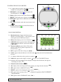
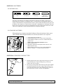
2.2 OPERATING KEYS OVERVIEW:
14. +/-: toggles between negative and positive values and
changes the counting direction
15. SEND DATA: sends data through the output ports
Serial/Digimatic or USB
16. in/mm: toggles between inches and millimeters
17. PRESET: recalls and resets a reference value
18. ZERO/ABS: toggles between ABSsolute and ZERO Mode
19. TOL: toggles tolerance mode and resets tolerance limits
20. ON/OFF: turns the indicator on and off and locks out
button functionality
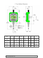
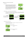
2.3 LCD DESCRIPTION
21. Directional arrows, display which direction the
indicator is measuring ( ) (i.e. value increases when
contact point moves in direction of arrow)
)
22. Battery icon, displays power level of batteries (
23. USB PWR indicator, appears when a USB connector is
plugged in and the indicator is powered by USB port
( USB PWR )
24. Tolerance Symbols, (only visible in TOL mode)
displays greater than, less than or equal to the set
tolerance limits (
)
25. DATA, appears when data is being sent ( DATA )
26. LOCK, appears when the indicator is in LOCK mode (
are active
) Only the On/Off and Send buttons
27. +/-, displays whether the value is positive or negative (
)
28. Underscore, appears when a digit is selected (
) (Used to set TOL/PRESET Values)
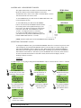
29. in, displays when measuring in inches (displays four digits after the decimal; last digit can
only display a 0 and 5) ( in )
30. Numerical values location (
)
31. mm, displays when measuring in millimeters (displays two digits after the decimal) ( mm )
32. ABS, appears when in ABSOLUTE mode ( ABS )
33. PRESET, appears when changing the preset value ( PRESET )
34. SET, appears when resetting a value ( SET ) (flashes for a portion of the TOL/PRESET
setup operations)
35. TOL, appears when in TOLERANCE mode ( TOL )
www.lmicorporation.com
6