1
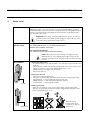
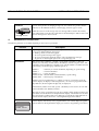
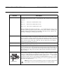
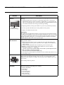
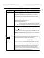
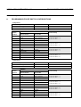
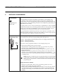
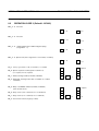
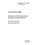
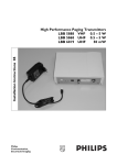
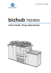
INSTALLATION
INSTRUCTION
DP 6000 DIGITAL PAGING SYSTEM
96A
9922 141 81241 en October 2003. Page 1
BOSCH DP6000
Generation IV VHF -UHF FM Paging Receivers
LBB 609x/xx - LBB 619x/xx
Table of contents
Page
Introduction ......................................................................... 1
Type Numbers ..................................................................... 3
Power supply ....................................................................... 4
Receiver built-in functions ................................................. 5
User Switch Function Tables ............................................. 15
Programmable Slide Switch Configurations .................... 17
Installer Monitor and Test Functions ................................ 20
Installer Programming ....................................................... 23
1.
INTRODUCTION
Intended for use in a Bosch DP6000 Digital paging system, the Generation IV range of receivers are fully compatible with the
existing and former range of Generation I, II, III receivers and transceivers. This extensive range of receivers gives a wide choice
of functions to cover the majority of specific paging requirements.
The receivers provide the following depending on the type number:
•
•
•
•
•
To give an LED indication when paged.
To bleep, vibrate or both when paged.
To receive spoken messages when paged.
To receive and manage displayed numeric or alphanumeric messages.
To generate an absent signal when placed in a storage/charging rack.
Security Systems
DP 6000 DIGITAL PAGING SYSTEM
INSTALLATION INSTRUCTION 96A
Octobery 2003. Page 2
Rear view
Front view
A
C
B
1
1
2
3
4
5
6
7
8
9
Bosch
(see
section 4)
2
3
4
5
7
6
8
9
Low battery indication
Out-of range indicator
Programming mode
Decimal Group call enabled
Bleep OFF/SOFT/LOUD
Speech OFF/ON
Telemetry message indicator
Message No.
Message scroll (> 24 characters)
D
E
F
(see
section 3.)
G
Battery placement/Utility switch
Side view
Top view
M
H
N
(see
section 4.)
L
Bottom view
1
2
3
Programming
dependent
(see section 4.)
J
K
II
CHARACTER SET FOR ALPHA DISPLAY
2 x LR1
(see section 3.)
O
P
I
0
1
2
3
Programming (see section 3 & 4)
Disposable batteries
Rechargeable batteries
1*
2*
Key to Symbols
A Vibrator (not applicable for EX intrinsic versions)
B Alphanumeric display with back-lighting
C Icon bar on display (user operation)
D Clip attachment (pocket)
E Battery cover lock (slide to open)
F Battery compartment
G Label placement
H 5-digit numeric display
J
K
L
M
N
O
P
Battery cover locking screw (EX versions only)
Charging/programming/absent contacts
LED indicator
RESET/RECALL/DELETE button
User switch (3-position)
Battery placement (see section 3.)
Utility 3-position sliding switch
FIGURE 1. Layout Generation IV receivers (illustrated version type LBB 6x94/xx)
INSTALLATION INSTRUCTION 96A
DP 6000 DIGITAL PAGING SYSTEM
October 2003. Page 3
2.
TYPE NUMBERS
This Installation Instruction covers the following type numbers (see Table 1):
Type Number
Description
Colour
LBB 6091/xx
UHF - FM bleep/numeric
Light
LBB 6092/xx
UHF - FM bleep/speech/numeric/vibrator
Light
LBB 6093/xx
UHF - FM bleep/numeric/alphanumeric
Light
LBB 6094/xx
UHF - FM bleep/speech/numeric/alphanumeric/vibrator
Light
LBB 6096/xx
UHF - FM bleep/numeric
Dark
LBB 6097/xx
UHF - FM bleep/speech/numeric/vibrator
Dark
LBB 6098/xx
UHF - FM bleep/numeric/alphanumeric
Dark
LBB 6099/xx
UHF - FM bleep/speech/numeric/alphanumeric/vibrator
Dark
LBB 6191/xx
VHF - FM bleep/numeric
Light
LBB 6192/xx
VHF - FM bleep/speech/numeric/vibrator
Light
LBB 6193/xx
VHF - FM bleep/numeric/alphanumeric
Light
LBB 6194/xx
VHF - FM bleep/speech/numeric/alphanumeric/vibrator
Light
LBB 6196/xx
VHF - FM bleep/numeric
Dark
LBB 6197/xx
VHF - FM bleep/speech/numeric/vibrator
Dark
LBB 6198/xx
VHF - FM bleep/numeric/alphanumeric
Dark
LBB 6199/xx
VHF - FM bleep/speech/numeric/alphanumeric/vibrator
Dark
LBB 5304/05
Leather pouch for belt attachment
n/a
LBB 5931/02
Rechargeable NiCAD batteries (set of 2)
n/a
LBB 5931/28
Rechargeable NiMH batteries (set of 28)
n/a
ACCESSORIES
NOTE: For ATEX approval please refer to Installation Instruction No. 96B.
/xx denotes the selected frequency of the receiver and its EX approval.
All receivers are available in EX-versions (class Eex ib IIc T6).
EX versions have no vibrator functions.
Light colours = Dark mushroom
Dark colours= Charcoal
DP 6000 DIGITAL PAGING SYSTEM
INSTALLATION INSTRUCTION 96A
Octobery 2003. Page 4
3.
POWER SUPPLY
INTRODUCTION
The power to the receivers is supplied by two LRI sized rechargeable or non-rechargeable batteries (figure. 1(O)) or by a single 3 V (non-rechargeable) lithium type Sanyo
CR12600 SE battery. The choice between rechargeable and non-rechargeable batteries is
made by a 3-position switch located inside the receivers battery compartment (figure.
1(P)). See Battery placement.
WARNING: Never charge non-rechargeable batteries. Always place the programming switch in the middle position (2) (figure. 1(P)) for this type of batteries. Never leave dead batteries in the receiver
RECOMMENDED
BATTERY TYPES
Rechargeable:
LR1 NiCAD (LBB 5931/02) or LR1 NiMH (LBB 5931/28) or
batteries with an identical specification.
Non-rechargeable batteries:
LR1 Alkaline or batteries with an identical specification.
NOTE: When placed in a Bosch storage or charging rack type
LBB 6150/00, /01, /02 or LBB 6152/00 (single storage rack) the
receiver is powered from the charging/storage rack and not from the
batteries.
REPLACEMENT
2 x LR1
1. Opening the battery cover
• To open the battery cover, slide the battery cover lock (figure.1 (E)) in the direction
of the clip.
• Use the special tool (EX versions only) delivered with the receiver to unscrew the
locking screw (figure. 1( J)) located underneath the battery cover.
• Slide the battery cover (figure.1(F)) downwards
• Remove the battery(s)
2. Battery type selection
• Remove the battery(s) (figure.1(O))
• Locate the 3-position utility slide switch inside the battery housing (figure.1(P)).
• Upper Position 1 = Programming/diagnostics mode only
• Middle Position 2 = Non rechargeable disposable batteries
• Lower Position 3 = Rechargeable batteries
3. Battery replacement
• Place the new battery(s) in the correct position (figure.1(O)) If rechargeable
batteries are used ensure the batteries are fully charged before using the receiver.
• Close and lock the battery cover.
1
2
3
Utility switch
When discarding
batteries follow local
regulations for disposal
instructions.
DP 6000 DIGITAL PAGING SYSTEM
INSTALLATION INSTRUCTION 96A
Octobery 2003. Page 5
BATTERY CHARGING
CONTACTS
Charging contacts
4.
The receiver has three contacts (figure.1(K)) used for charging and programming the
receiver when placed in its charging/storage rack. One contact also provides ‘Absent’
indication via the DP6000 encoder(s). The charging current is approx. 10 mA.
While the receiver is in the storage rack, new messages will be stored in the memory
stack. When taken out of the rack it will emit two attention bleeps to indicate to the user
that new messages have been received.
RECEIVER BUILT-IN FUNCTIONS
The following functions are available depending on the receiver type number.
Description
Function
INTRODUCTION
Depending on the type number, the receivers provide the following basic functions:
1. To give an LED indication when paged.
2. To bleep, vibrate or both when paged.
3. To receive spoken messages when paged.
4. To receive and manage displayed numeric and/or alphanumeric messages.
5. To generate an absent signal if placed in a storage/charging rack.
ADDRESSES
Each receiver has 8 addresses: 1 normal, 5 group (fixed or dynamic), 1 ALL-call
(CCCC) and 1 telemetry/normal address. All addresses with the exception of the ALLcall address can be included in a ‘decimal group’ call. The installer can disable the ALLcall, telemetry and decimal group addresses (opcode 1).
Address 0
Address 1
Address 2 - 6
Address CCCC
Address xFFF
= telemetry or normal call address (depending on opcode setting)
= normal call address
= group call address
= all call address (enable/disable by opcode setting)
= decimal group call addresses
Addresses can be programmed for 4 or 7-digits (opcode 1S). In stand-by mode, the
numeric display can display 4 address digits (max.). For receivers programmed with 7digit addresses, the least significant digits only are displayed.
If the telemetry address is not used (opcode 1, disabled) it can be used as an extra individual call address. See Telemetry function.
The receiver can be programmed (opcode 1U) to display (during stand-by mode) its normal address on both the numeric and alphanumeric display. The installer can also determine the number of address digits to be displayed (opcode 2R). If 7-digit addresses are
used the numeric display shows max. 4 least significant digits of the address.
USER NAME
1234567
JOHN SMITH
The receiver can be programmed to incorporate a user name (e.g. John Smith) for alphanumeric display versions only. Once programmed the user name is displayed together
with its address on the alphanumeric display (see section 6. Programming User Name).
DP 6000 DIGITAL PAGING SYSTEM
INSTALLATION INSTRUCTION 96A
Octobery 2003. Page 6
Function
Description
SYSTEM IDENTITY
System Identity
The System identity (range HEX 0 - HEX 3) is transmitted with the ‘mode word’ in the
DP6000 code to separate two neighbouring systems which are operated on the same
frequency. This feature can only be used in systems where this function has been
implemented in the central desk. The system ID digit (opcode 1Q ) at present should
be set to ‘0’. This value is of no importance to the programming calls.
NORMAL CALL
(including speech)
Normal calls are calls addressed to a receiver with an assigned address.
A Normal call to a receiver can include coded messages with different bleep patterns,
vibration and/or light signals, or messages on a numeric and/or alpha-numeric display.
One way speech messages are also possible between an encoder and the paging receiver.
Normal calls therefore can comprise:
Bleep/vibration/LED indication with 5-digit (10-digit information is possible) and 24character alphanumeric information (48-character messages are also possible). All calls
can be accompanied with speech messages.
GROUP CALL
Paging call to a group of paging receivers (programmable) by ‘Group’ call (fixed or
dynamic) (e.g. 2222), or ‘decimal group’ call (e.g. 2- - - where receiver 2000 to 2999 are
called).
When the receiver is called by one of its group call addresses, it will emit a cricketed
bleep tone corresponding to the number being entered (e.g. when entering bleep code
No.3, the bleep pattern will be 8 + 3 is call tone B (see Bleep Vibrator patterns)). The
receiver will not generate an absence signal when housed in its storage rack and when
called by one of its group call addresses.
The programmable group call addresses (2 - 6) in the receiver can be fixed or dynamic.
The address is fixed if, via address programming (see section 5.) an address has been
programmed in one of the group call addresses. If the group call address is not programmed and contains address [CCC]CCCC, this address can be used as a dynamic
group call address.
The dynamic group call function enables the system to include or remove a pager holder
from a specified group of pager holders, without having to put the receiver into the programming mode. This function is done by transmitting special calls and can be used for
special applications to create flexible groups within a system (e.g different shift working
patterns).
To remove the dynamic group addresses proceed as follows:
- placing the receiver in a rack (this function can be enabled/disabled (Opcode 1R).
- switching the receiver OFF and ON again.
- via a special call from a system encoder (e.g. alpha desk)
It is also possible to program the receivers addresses 0 to 6 (enabled/disabled by opcode
setting and/or 3-position user switch) to respond to a decimal group call. The “ - “ key on
the desk can then be used to call a group of receivers as follows:
If the character “ - “ is entered in place of a call number digit , this will replace all numbers 0 - 9 in that call number location. In 4-digit addresses, the character “- “ can be
entered in place of any of the last three digits of the call number. In 7-digit addresses, the
character “-” can be entered in place of any of the last 6-digits.
INSTALLATION INSTRUCTION 96A
DP 6000 DIGITAL PAGING SYSTEM
October 2003. Page 7
Function
GROUP CALL (contd.)
Description
Assuming that no call number digits have been pre-programmed in the desk and all 4
call number digits must be keyed in. A decimal group call can therefore be transmitted
as follows:
Key in 1 - - -calls receiver numbers1000 to 1999
Key in 14 - -calls receiver numbers1400 to 1499
Key in 159 -calls receiver numbers1590 to 1599
Bearing in mind that all digits apart from the “ - “ are variable between 0 and 9, you can
see that any selected group of 10, 100 or 1000 receivers can be called as a decimal group
call. This must be born in mind when the installer is allocating receiver addresses and
enabling or disabling the decimal group call facility.
ALL-CALL
This address is not programmable and is the same for all receivers in the system and it
would normally be used in an emergency situation where every receiver holder would
have to respond to a single call (The fixed value for this address is “CCCC”). This call
will be received even if the receiver is programmed for “don’t disturb” The receiver will
always enter the speech mode after an All Call. The use of this call can be enabled or
disabled by programming (opcode 1S).
TELEMETRY CALL
Paging calls with telemetry information to a specific telemetry address. The message is
stored in a specific location in the stack.
DISPLAY MESSAGES
Messages may consist of 5-digit numeric information, a 24 character alphanumeric message or both. The receiver will automatically show the message in the relevant display. If
a message contains only a 5-digit numeric info the alphanumeric display will also display
this information. If a call is received without 5-digit numeric information, the numeric
display will show (- - - - - ).
NUMERIC DISPLAY
The Numeric display can display the receiver’s address or 5-digit numeric information
accompanying a paging call. A 10-digit numeric message can also accompany a paging
call (i.e 2 x 5-digit messages are transmitted). In this case the message will be converted
for display on the alphanumeric display (the numeric display shows - - - - - ). For versions
with numeric display only, the user should use the RESET/RECALL button to scroll the
remainder of the message (see Message handling). If a receiver is paged without numeric
information the displays shows: - - - - - .
5-digit display
NOTE: The receiver can be programmed (opcode 1U) to display (during standby) its address or the last received information before or during standby.
DP 6000 DIGITAL PAGING SYSTEM
INSTALLATION INSTRUCTION 96A
Octobery 2003. Page 8
Function
ALPHANUMERIC
DISPLAY
Description
The 24-character LC-display with back-lighting (see back-lighting) is intended for the
following:
1. Displaying alphanumeric messages accompanying paging calls. A 48-character
alphanumeric message can also accompany a paging call (i.e 2 x 24-character messages are transmitted). In this case the user should use the RESET/RECALL button
to scroll the remainder of the message (see Message handling).
2. Displaying telemetry messages (if enabled via opcode 1T) (see Telemetry function)
Alphanumeric
24-character display
3. To view opcodes and address (See viewing addresses and opcodes)
4. Display own address and user name
Back-lighting
Back-lighting for the alphanumeric display is incorporated for use in badly lit situations.
If enabled for back-lighting (opcode 1U) the display will illuminate with every incoming
call containing alphanumeric information and when scrolling through the message stack.
The light will switch OFF approx. 8 seconds after the bleep or after 10 seconds if the
RESET/RECALL button has not been pressed again.
VIEWING ADDRESSES
AND OPCODES
To view the receiver’s address and opcodes while the receiver is in its normal operation
mode proceed as follows:
1. Remove the receiver from its rack or switch the receiver ON while keeping the
RESET/RECALL button pressed. Both the receiver displays show the firmware/
release version.
2. Using the RESET/RECALL button the following can be viewed in order:
- addresses 0 - 6 (in the numeric display 7-digit addresses are shown as follows:
alternating ( ¯AA6A5A4 to ¯A3A2A1A0)
- opcodes 1 and 2 (in the numeric display, only the last 5 opcode digits are shown
(digit 1 of opcode 1 and 2 are not used))
- user name (receivers with alpha display only)
3. If no button is pressed within 10 seconds the receiver automatically returns to it normal ‘standby’ mode.
LED INDICATION
The LED indicator (figure 1L) indicates an incoming call. The LED flashes during the
bleep and for 8 seconds after the bleep. If the receiver is set to bleep/vibrate until
‘RESET’ the LED will flash according to the same pattern until a RESET is given (max.
255 seconds).
See also Bleep/Vibration patterns.
LED indicator
BLEEP/VIBRATOR
PATTERNS
Bleep/vibration patterns
The following bleep patterns/bleeps are available:
1. Normal call patterns
2. Alert bleeps
3. Error bleeps
4. Out-of-range bleep
5. Low battery bleep
6. Shut-down bleep
7. Programming bleep
INSTALLATION INSTRUCTION 96A
DP 6000 DIGITAL PAGING SYSTEM
October 2003. Page 9
A
B
C
D
Function
Description
NORMAL CALL BLEEP
PATTERNS
The receiver can be called with 14 different bleep/vibration patterns (7 normal patterns
and 7 cricketed patterns) or with a silent call. In vibrator types the cricketed pattern is
treated as a normal pattern. Each bleep pattern is assigned a codinf (code information)
digit for use in accompanying ‘NORMAL’ calls (1 - 14). The bleep tone can be enabled
or disabled depending on the opcode programming (opcode 2U).
When a call is made to a ‘GROUP’ call address the receiver will always bleep with a
cricketed tone. Bleep tones/vibration can be stopped by pressing the ‘RESET/RECALL
L M N
J K
’ button, or on time-out. If a second call is received while the receiver is still bleeping the
bleep will cease and the new incoming bleep will takeover. The volume of the bleep
tones can be set by the installer (opcode 2U), its volume level indication shown in the
Icon bar on the display (1C(E)).
Bleep LOUD
E
F
G
Bleep SOFT
No ICON = SILENT
bleep
H
Normal call bleep patterns
0/8
1/9
2/A
3/B
4/C
5/D
6/E
7/F
Silent call
Bleep pattern 0 - 6 = normal tone
Bleep pattern 8 - E = cricketed tone
The levels of the above bleep patterns are dependent on the OPCODE set and the 3position user switch (see 3-position user switch). During an urgent call or a call with manual request, the bleep volume will always be loud.
DP 6000 DIGITAL PAGING SYSTEM
INSTALLATION INSTRUCTION 96A
Octobery 2003. Page 10
Function
Description
ATTENTION BLEEP
Attention bleep
The attention bleep is emitted to alert the attention of the user. The bleep and LED patterns are shown below:
Soft bleep
LED
8 x 33 msec.
The user is alerted with this pattern under the following conditions:
1. Switching the receiver ON/OFF
2. When set to silent bleep and a call is received
3. Placing and removing the receiver from its charging/storage rack
4. Change of user switch position
5. Acknowledge when deleting messages.
6. Reaching end of message stack when scrolling
7. Bring receiver back-in range when taken out-of-range (see out-of-range bleep)
8. Depending on the bleep pattern digit of the programming call for a dynamic group
call address the attention bleep can be generated (bleep pattern digit does not equal
F)
When a receiver is removed from its storage rack and it has received new messages
while in the rack, the receiver will emit a second attention bleep after the ‘out-of-rack’
bleep.
OUT-OF-RANGE
DETECTION
Out-of-range bleep
The out-of-range bleep (programmable opcode 1U) is emitted when the receiver has
been detected as out-of-range (see Out-of-range). See pattern and description below:
until reset
soft bleep
8 x 33 msec.
A
D
B C icon
Out-of-range
(figure 1C(B))
E
F
G
H
J
K
L
M
N
Description Out-of-range
All receivers incorporate an ‘Out-of range’ function to alert the user when the receiver
has been taken out-of-range of the system transmitters. An encoder in the DP6000 system transmits an ‘out-of-range’ signal every 30 seconds, if a receiver fails to receive any
valid DP6000 call within approx. 60 seconds, it will generate the ‘out-of-range’ bleep to
the receiver/user. Out-of-range is indicated as follows:
1. The receiver emits a bleep signal until RESET by the user. The bleep until RESET
function is used with a ‘time-out’ of 62.5 seconds.
2. Visual display: Alphanumeric display show out-of-range icon . Numeric display only
version: shows (0 - 0 - 0) alternating with (- 0 - 0 -).
To RESET the receiver in ‘Out-of-range’ state proceed as follows:
1. Bring the receiver back into range of the DP6000 system transmitters.
2. If not brought back-in range within 30 minutes the receiver switches OFF automatically after first emitting a loud continuous warning bleep (approx 1 second). Once the
receiver has been automatically switched OFF, it can be switched ON by placing the
3-position switch to ON from OFF or by placing the receiver into its charging/storage
rack (except single storage rack LBB 6152/00).
INSTALLATION INSTRUCTION 96A
DP 6000 DIGITAL PAGING SYSTEM
October 2003. Page 11
Function
LOW BATTERY
A
Low battery
icon D
B C
(figure 1C(A))
Description
Low battery bleep
In low battery state (programmable opcode 1U) the following bleep pattern is emitted:
E
F
G
H
J
8Kx 33 msec.
L
M
N
1x
soft bleep
:
The receiver in ‘low battery state’ will give an audible (low volume bleep) every 255 seconds and/or display warning by the low battery icon which will be on constantly during
low battery state. In this state the batteries must be replaced or the receiver must be
placed in its charging/storage rack. The ‘low battery state’ warning bleep can be disabled/enabled via opcode programming (see programming opcodes). The display warning is dependent on the type of receiver (i.e alphanumeric display).
In the alphanumeric display the ‘Low battery’ icon is ON and the numeric display
flashes. After 1 hour of low battery the receiver switches off automatically after first emitting the ‘shut-down’ bleep.
BATTERY SAVING
In battery saving mode (programmable opcode 1S (5F-string)), the HF section of the
receiver is switched ON/OFF periodically to reduce receiver current consumption. A
preamble string is transmitted before each call to switch the HF section ON before a call
is transmitted. The HF section remains ON for a set time to ensure that a second call is
not missed.
ERROR BLEEP
Error bleep
The receiver emits an error bleep to indicate user input error. See pattern below:
8 x 33 msec.
1x
soft bleep
Error bleep: to indicate user input error (e.g. if the user tries to delete messages while this
function is disabled by the installer).
SHUTDOWN BLEEP
Shutdown bleep
The shut-down bleep is emitted when the receiver switches itself OFF automatically. See
pattern below:
8 x 133 msec.
1x
loud bleep
The shut-down bleep is emitted after 30 seconds of continuous ‘out-of-range’ or after 1
hour of continuous low battery.
BLEEP UNTIL RESET
Reset/Recall button
Bleep until RESET
The receiver can be set by the installer to ‘bleep until RESET’ (i.e the receiver bleeps
until the ‘RESET’ button is pressed. If a ‘RESET’ is not given within 60 seconds the
bleep pattern will be repeated after 30 seconds of silence. The procedure will be
repeated until RESET for a maximum period of 255 seconds.
When the receiver is called with an urgent call or with a call with a manual request
(these functions are determined by the ‘modeword’ in the DP6000 call string) the
receiver will respond with a bleep until reset independent of the opcode setting.
DP 6000 DIGITAL PAGING SYSTEM
INSTALLATION INSTRUCTION 96A
Octobery 2003. Page 12
Function
G
VIBRATOR
Vibrator call patterns
Receiver types with vibrator are able to vibrate in unison with 7 different patterns
(depending on ‘codinf’). Cricketed vibration patterns are identical to the normal vibration patterns.
MESSAGE HANDLING
Message handling (numeric and alphanumeric)
Each call to a receiver can contain 5-digit numeric and/or max. 48-character alphanumeric messages (see Numeric and alphanumeric display). The receiver contains a
memory stack for messages and telemetry information (see Telemetry function). The
number of messages stored in the message stack is 10 + 1 Telemetry message (if enabled).
The memory stacks operate in a First-In-First-Out (FIFO) basis. If two identical messages/information are sent to a receiver, the last message only will remain in the stack.
Dependent on the modeword of the paging call, messages will be stored or not stored in
the message stack.
Stack number of
H J being
message
viewed
G
H
Description
Press the RECALL
J to view the
button
remaining part of the
alphanumeric message
The receiver can also handle 48 character messages which are sent as two calls (first call
sent with codinf F) within 4 seconds. These two parts are then combined as a single
message. In the display this is indicated with the icon blinking if the first 24 characters
of the message
( fig.1C ( J)) if the second 24 charac1 2are 3displayed
4
5
6and with the7
8 icon
9
ters are displayed.
1 2
7
3 4
5
6
8
9
If the message is not meant for storage in the stack it will be displayed until the RECALL
button is pressed (depending on standby setting).When the receiver is programmed to
display its own address during ‘standby’ this message remains in the display until timeout (8 seconds after the bleep has ended). Such a message will not have an index number
(i.e MESSAGE NUMBER icon blank).
If a message contains both numeric and alphanumeric information while scrolling, the
receiver gives a short flash of the LED to indicate that the message also contains alphanumeric information. Messages in the memory stack can be recalled/scrolled and
deleted using the RESET/RECALL/DELETE button (figure 1M).
REMARK: The DP6000 callstring can contain the following sections:
1. address (5-digit HEX) (receiver call number)
2. Numeric information (5-digit HEX) displayed on the 5-digit numeric LC-display
3. Mode word (5-digit HEX) (function control)
4. Alphanumeric message displayed on the 24-character alphanumeric LC-display
RECALLING/SCROLLING MESSAGES
The Message handling icon indicates the stack number of the message being viewed.
1. To view the messages from the message stack, press the RECALL/RESET button to
scroll. If back-lighting is enabled the RECALL/RESET button should be pressed
twice to start scrolling (the first press switches the back-light ON).
2. A bleep is emitted when the end of the message stack is reached. If the button is not
pressed for approx. 8 seconds the receiver returns to its ‘standby’ mode displaying
the last stored message (or if set the receiver’s address).
INSTALLATION INSTRUCTION 96A
DP 6000 DIGITAL PAGING SYSTEM
October 2003. Page 13
Function
Description
MESSAGE HANDLING
(contd.)
DELETING MESSAGES IN STACK
Deleting messages from the stack is an installer option (opcode 2T). If enabled messages
can be deleted as follows:
1. Scroll using the RESET/RECALL button until the message to be deleted is displayed.
Once displayed, press the RESET/RECALL button again for approx. 3 seconds to
delete the displayed message. An alert bleep indicates the message has been deleted.
DELETING ALL MESSAGES IN STACK
Deleting ALL messages in the stack is an installer option (opcode 2T). If enabled ALL
messages will be deleted as follows:
1. When the receiver is placed in the storage rack.
2. When the receiver is switched OFF
NOTE: While the receiver is in the storage rack, new messages will be
stored in the memory stack. When taken out of the rack it will emit
two attention bleeps to indicate to the user that new messages have
been received.
ERRORS IN
MESSAGES
ERROR IN MESSAGE DETECTION
The receiver can be programmed (opcode 1T) to accept or reject errors in alphanumeric or numeric messages. For versions with alphanumeric displays a max. of 3
errors in a message can be accepted (characters with errors are displayed as ‘checkboard’ signs ) or rejected.
Calls without numeric info are either accepted or rejected (programmable opcode 1T).
REMARK: In older DP6000 systems, encoders may be present, where the DP6000 callstring consists of the receiver address only (i.e. IPA coupler LBB 5940/03). For use of
these receivers in these systems, calls ‘without info’ should be accepted.
TELEMETRY
FUNCTION
G
H
J
K
L
M
The telemetry function (Mailbox) is only available for version with alphanumeric
display. This function is intended to provide users with continuous up-to-date information (e.g process control (max. 48-character)). To receive telemetry information the
receiver must be programmed for a telemetry address (see addresses).
N
If the telemetry function is enabled one memory stack place (first level) is reserved for
receiving this message (address 0 is used as the telemetry address).
The user can be alerted or not alerted depending on the bleep pattern digit (codinf) of
the telemetry call. If the telemetry call is sent as a silent call (codinf ‘F’) the message is
written directly to the top level of the message stack and not to the display. The user is
informed by a flashing telemetry icon. To view the message press the RESET/RECALL
button. If the telemetry call includes a bleep pattern ( HEX 0 - HEX E) the message is
written to the top level of the memory stack and also to the alphanumeric display. The
telemetry icon is ON. Depending on the ‘standby’ setting (opcode 1U) this message
remains in the display or it will return to displaying the normal receiver address.
The telemetry icon will be permanently ON while the telemetry message is in the
display.
The telemetry function can be enabled or disabled (opcode 1T).
DP 6000 DIGITAL PAGING SYSTEM
INSTALLATION INSTRUCTION 96A
Octobery 2003. Page 14
Function
Description
SPEECH FUNCTION
2
3
4
5
Speech (applicable for LBB 6X92, 6X94, 6X97 and 6x99 only)
The functions that can be programmed for speech can be set in opcode 2.
If ‘always speech’ after a call is enabled (opcode 2T) the receiver will switch to speech
every call that doesn’t have a “mode word”. If the call is sent with a ‘mode word’,
7after
8
9
the speech setting of the ‘mode word’ has priority over this function.
6
Speech coupled to codeinf (6 or 7) (opcode 2T) enables the receiver being switched to
speech by calls without mode word depending on the bleep pattern digit. If the codeinf
digit is 6 or 7 and this function is enabled the receiver will automatically switch to
speech. If the call is sent with a ‘mode word’, the speech setting of the ‘mode word’ has
priority over this function.
Maximum speech time can be set using opcode 2S (range 0 to 140 seconds or infinite).
Normally speech is reset by a speech reset call from the encoder.
The speech icon in alphanumeric speech receivers will be visible if the programmed
speech time does not equal ‘0’.
3-POSITION USER
SWITCH
The function of the 3-position user switch (figure 1N) is programming dependent
(opcode 1 and 2) and dependent on the type of receiver (with or without vibrator).
A combination of the following functions can be programmed:
1. Switch the receiver ON/OFF
2. Switch the volume of the bleep between silent, soft and loud
3. Enable/disable decimal group calls for this receiver
Table 3 shows the switch functions depending on the opcode settings (opcode 1T decimal group call enabled/disabled and opcode 2U user switch group or alert).
User switch
Table 4. shows the functions for position 0 of the 3-position user switch depending on the
opcode setting 1S (power OFF enabled/disabled and if the receiver includes a vibrator).
Table 5 and 6 shows the function for position I and II of the 3-position switch depending
on the opcode setting 2U (bleep volume and user switch functions (group or alert)) and if
the receiver includes a vibrator.
A
B
C
D
Bleep
E volume
F icon
G
(figure 1C(E))
H
J
K
L
M
N
See 5. USER SWITCH FUNCTION TABLES:
NOTE: Fill-in the customer specific programming of the 3-position
user switch in the user manual.
A
A
B
C
B
D
C
Decimal
group
D
E E
F call
FG
icon (figure 1C(D))
H
G
H
J
KJ
KL
L
M
M
N
N
INSTALLATION INSTRUCTION 96A
DP 6000 DIGITAL PAGING SYSTEM
October 2003. Page 15
5.
USER SWITCH FUNCTION TABLES
OPCODE
Decimal group call (enable/disable) Opcode 1T
Switch function setting
(group or alert) Opcode 2U
Switch function
(pos. I & II)
decimal group disabled (opcode bit = 0)
X (don’t care)
Alert
decimal group enabled (opcode bit = 1)
1 (bleep)
Alert
decimal group enabled (opcode bit = 1)
0 (group)
Group
Opcode 1S
Power OFF (enable/disable)
Bleep volume
Receiver without vibrator
(Switch pos. 0)
Receiver with vibrator
(Switch pos. 0)
disabled
< >11*
silent bleep
vibrator
disabled
11*
soft bleep
vibrator + soft bleep
enabled
x (don’t care)
receiver OFF
receiver OFF
*bleep volume 11: = don’t disturb is not possible, the receiver will always bleep.
SWITCH POSITION I and II (OPCODE 1T and 2U) (Function Switch set to ALERT)
OPCODE
Switch
Function
Receiver without vibrator
Receiver with vibrator
1T
Decimal
group
2U
Bleep
Volume
Position I
Position II
Position I
Position II
ALERT
0
00
grp = disabled
alert = silent
grp =disabled
alert = soft
grp = disabled
alert = vib
grp = vib
alert = silent
ALERT
0
01
grp = disabled
alert = silent
grp = disabled
alert = loud
grp = disabled
alert = vib
grp = disabled
alert = soft
ALERT
0
10
grp = disabled
alert = soft
grp = disabled
alert = loud
grp = disabled
alert = vib
grp = disabled
alert = loud
ALERT
0
11
grp = disabled
alert = loud
grp = disabled
alert = loud
grp = disabled
alert =vib + loud
grp = disabled
alert = vib + loud
ALERT
1
00
grp = enabled
alert = silent
grp = enabled
alert = soft
grp = enabled
alert = vib
grp = enabled
alert = silent
ALERT
1
01
grp = enabled
alert = silent
grp = enabled
alert = loud
grp = enabled
alert = vib
grp = enabled
alert = soft
ALERT
1
10
grp = enabled
alert = soft
grp = enabled
alert = loud
grp = enabled
alert = vib
grp = enabled
alert = loud
ALERT
1
11
grp = enabled
alert = loud
grp = enabled
alert = loud
grp = enabled
alert = vib + loud
grp = enabled
alert = vib + loud
DP 6000 DIGITAL PAGING SYSTEM
INSTALLATION INSTRUCTION 96A
Octobery 2003. Page 16
SWITCH POSITION I and II (OPCODE 1T and 2U) (Function Switch set to GROUP)
OPCODE
Switch
Function
Receiver without vibrator
Receiver with vibrator
1T
Decimal
group
2U
Bleep
Volume
Position I
Position II
Position I
Position II
GROUP
1
0X
grp = disabled
alert = silent
grp =enabled
alert = silent
grp = disabled
alert = vib
grp = enabled
alert = vib
GROUP
1
10
grp = disabled
alert = soft
grp = enabled
alert = soft
grp = disabled
alert = vib + soft
grp = enabled
alert = vib + soft
GROUP
1
11
grp = disabled
alert = loud
grp = enabled
alert = loud
grp = disabled
alert = vib + loud
grp = enabled
alert = vib + loud
*Generally the decimal group call can be enabled or disabled when the switch function is set to alert
Bleep Volume with Function switch set to I or II
OPCODE 2U (BIT 1 and 2)
Receiver without vibrator
Receiver with vibrator
00
silent/soft
vib/silent
01
silent/loud
vib/soft
10
soft/loud
vib/loud
11
loud/loud
(vib+loud)/(vib/loud)
REMARK: For ease of use refer to 6. Programmable Slide Switch Configuration, which give the possible user switch
configurations and their relevant opcode settings:
INSTALLATION INSTRUCTION 96A
DP 6000 DIGITAL PAGING SYSTEM
October 2003. Page 17
6.
PROGRAMMABLE SLIDE SWITCH CONFIGURATIONS
Configuration 1
Decimal Group Call
DISABLED
Opcode 1T: Bit 2 = 0
Power OFF Switching
ENABLED
Opcode 1S: Bit 3 = 1
Function Slide Switch
DON’T CARE
Opcode 2U: Bit 0 = 1 / 0
Volume Setting
Function
Switch
Position
Receiver
without vibrator
Receiver
with vibrator
II
Loud
Loud + vibrator
I
Loud
Loud + vibrator
0
Power OFF
Power OFF
II
Loud
Loud
I
Soft
Vibrator
0
Power OFF
Power OFF
II
Loud
Soft
I
Silent
Vibrator
0
Power OFF
Power OFF
II
Soft
Silent
I
Silent
Vibrator
0
Power OFF
Power OFF
Opcode 2U: Bit 2 = 1
Opcode 2U: Bit 1 = 1
Opcode 2U: Bit 2 = 1
Opcode 2U: Bit 1 = 0
Opcode 2U: Bit 2 = 0
Opcode 2U: Bit 1 = 1
Opcode 2U: Bit 2 = 0
Opcode 2U: Bit 2 = 0
Configuration 2
Decimal Group Call
DISABLED
Opcode 1T: Bit 2 = 0
Power OFF Switching
DISABLED
Opcode 1S: Bit 3 = 0
Function Slide Switch
DON’T CARE
Opcode 2U: Bit 0 = 1 / 0
Volume Setting
Function
Switch
Position
Receiver
without vibrator
Receiver
with vibrator
II
Loud
Loud + vibrator
I
Loud
Loud + vibrator
0
Soft
Soft + vibrator
II
Loud
Loud
I
Soft
Vibrator
0
Silent
Vibrator
II
Loud
Soft
I
Silent
Vibrator
0
Silent
Vibrator
II
Soft
Silent
I
Silent
Vibrator
0
Silent
Vibrator
Opcode 2U: Bit 2 = 1
Opcode 2U: Bit 1 = 1
Opcode 2U: Bit 2 = 1
Opcode 2U: Bit 1 = 0
Opcode 2U: Bit 2 = 0
Opcode 2U: Bit 1 = 1
Opcode 2U: Bit 2 = 0
Opcode 2U: Bit 1 = 0
DP 6000 DIGITAL PAGING SYSTEM
INSTALLATION INSTRUCTION 96A
Octobery 2003. Page 18
Configuration 3
Decimal Group Call
ENABLED
Opcode 1T: Bit 2 = 1
Power OFF Switching
ENABLED
Opcode 1S: Bit 3 = 1
Function Slide Switch
ALERT
Opcode 2U: Bit 0 = 1
Volume Setting
Function
Switch
Position
Receiver
without vibrator
Receiver
with vibrator
II
Loud
Loud + vibrator
I
Loud
Loud + vibrator
0
Power OFF
Power OFF
II
Loud
Loud
I
Soft
Vibrator
0
Power OFF
Power OFF
II
Loud
Soft
I
Silent
Vibrator
0
Power OFF
Power OFF
II
Soft
Silent
I
Silent
Vibrator
0
Power OFF
Power OFF
Opcode 2U: Bit 2 = 1
Opcode 2U: Bit 1 = 1
Opcode 2U: Bit 2 = 1
Opcode 2U: Bit 1 = 0
Opcode 2U: Bit 2 = 0
Opcode 2U: Bit 1 = 1
Opcode 2U: Bit 2 = 0
Opcode 2U: Bit 1 = 0
Configuration 4
Decimal Group Call
ENABLED
Opcode 1T: Bit 2 = 1
Power OFF Switching
DISABLED
Opcode 1S: Bit 3 = 1
Function Slide Switch
ALERT
Opcode 2U: Bit 0 = 1
Volume Setting
Function
Switch
Position
Receiver
without vibrator
Receiver
with vibrator
II
Loud
Loud + vibrator
I
Loud
Loud + vibrator
0
Soft
Soft + vibrator
II
Loud
Loud
I
Soft
Vibrator
0
Silent
Vibrator
II
Loud
Soft
I
Silent
Vibrator
0
Silent
Vibrator
II
Soft
Silent
I
Silent
Vibrator
0
Silent
Vibrator
Opcode 2U: Bit 2 = 1
Opcode 2U: Bit 1 = 1
Opcode 2U: Bit 2 = 1
Opcode 2U: Bit 1 = 0
Opcode 2U: Bit 2 = 0
Opcode 2U: Bit 1 = 1
Opcode 2U: Bit 2 = 0
Opcode 2U: Bit 1 = 0
INSTALLATION INSTRUCTION 96A
DP 6000 DIGITAL PAGING SYSTEM
October 2003. Page 19
Configuration 5
Decimal Group Call
ENABLED
Opcode 1T: Bit 2 = 1
Power OFF Switching
ENABLED
Opcode 1S: Bit 3 = 1
Function Slide Switch
GROUP
Opcode 2U: Bit 0 = 0
Volume Setting
Function
Switch
Position
Group
Bleep/Vibrator
II
Group ON
Loud + (vibrator)
I
Group OFF
Loud + (vibrator)
0
Power OFF
Power OFF
II
Group ON
Soft (+vibrator)
I
Group OFF
Soft (+vibrator)
0
Power OFF
Power OFF
II
Group ON
Silent (or vibrator)
I
Group OFF
Silent (or vibrator)
0
Power OFF
Power OFF
Opcode 2U: Bit 2 = 1
Opcode 2U: Bit 1 = 1
Opcode 2U: Bit 2 = 1
Opcode 2U: Bit 1 = 0
Opcode 2U: Bit 2 = 0
Opcode 2U: Bit 1 = don’t care
Configuration 6
Decimal Group Call
ENABLED
Opcode 1T: Bit 2 = 1
Power OFF Switching
DISABLED
Opcode 1S: Bit 3 = 0
Function Slide Switch
GROUP
Opcode 2U: Bit 0 = 0
Volume Setting
Function
Switch
Position
Group
Bleep/Vibrator
II
Group ON
Loud (+ vibrator)
I
Group OFF
Loud (+ vibrator)
0
Group OFF
Soft (+vibrator)
II
Group ON
Soft (+vibrator)
I
Group OFF
Soft (+vibrator)
0
Group OFF
Silent (or vibrator)
II
Group ON
Silent (or vibrator)
I
Group OFF
Silent (or vibrator)
0
Group OFF
Silent (or vibrator)
Opcode 2U: Bit 2 = 1
Opcode 2U: Bit 1 = 1
Opcode 2U: Bit 2 = 1
Opcode 2U: Bit 1 = 0
Opcode 2U: Bit 2 = 0
Opcode 2U: Bit 1 = don’t care
DP 6000 DIGITAL PAGING SYSTEM
INSTALLATION INSTRUCTION 96A
Octobery 2003. Page 20
7.
INSTALLER MONITOR AND TEST FUNCTIONS
MONITOR / TEST
FUNCTIONS
User switch
II
I
0
1
2
3
Programming
switch
MONITOR MODE
II
I
0
User switch
(position I)
To enter the Monitor and Test mode of the receiver proceed as follows:
1. Switch the receiver OFF (3-position user switch (fig. 1(N) in the lower position)
2. Open the battery compartment and remove the batteries.
3. Place the 3-position utility switch to its programming position (position 1 (fig. 1P)).
4. Replace the batteries.
5. Switch the receiver ON (3-position user switch to position I or II. The receiver
now enters the receiver ‘diagnostic standby mode’ showing the receiver firmware
version and type (e.g. N= numeric display, A = alphanumeric display, S= speech,
V = vibrator, X = intrinsically safe).
NOTE: While the 3-position utility switch is in the programming position the following is valid:
1. With the user switch in position 0 the receiver is always switched OFF independent of the opcode setting
2. The functions ‘low battery’ (bleep), ‘Out-of-range’ and battery saving are disabled.
3. In diagnostic standby mode the receiver is able to receive and handle calls. After a
call has been handled, the receiver returns to the diagnostic standby mode.
MONITOR MODE
With the User function switch (fig 1(N)) in the middle position the ‘Monitor’ standby
mode can be entered providing the following functions:
1. Address monitoring
2. Message monitoring
3. Speech monitoring
4. Call counter
ADDRESS MONITORING
While in the Monitor standby mode press the ‘RESET/RECALL’ button once (<2.5
seconds), the receiver enters the receiver address monitoring mode. The numeric display shows AAAAA. The alphanumeric display shows ‘CALL’. In this mode each
transmitted call in the system results in an attention bleep and the numeric display
shows the received address plus codinf. The alphanumeric display shows the address
plus codinf on the first line and the 5-digit numeric info and modeword on the second
line.
MESSAGE MONITORING
While in the address monitoring mode press the ‘RESET/RECALL’ button again
(<2.5 seconds) to enter the MESSAGE monitoring mode.
The numeric display shows ‘- - - - -’, the alphanumeric displays shows ‘MESSAGE’.
Each transmitted call in the system results in an attention bleep and the 5-digit
numeric info part of the call is displayed in the numeric display and the alphanumeric
message of each call is displayed in the alphanumeric display of the receiver.
SPEECH MONITORING
While in the MESSAGE monitoring mode press the ‘RESET/RECALL button (<2.5
seconds), to enter the SPEECH monitoring mode. The numeric display shows:
‘- - - - -’ , and the alphanumeric display shows .SPEECH’. In this mode it is possible
to switch the speech reproduction ON and OFF. To switch OFF speech press the
‘RESET/RECALL’ button for longer than 2.5 seconds. To listen to the speech in the
system press the ‘RESET/RECALL’ button again for longer than 2.5 seconds.
INSTALLATION INSTRUCTION 96A
DP 6000 DIGITAL PAGING SYSTEM
October 2003. Page 21
CALL COUNTER
While in the speech monitoring mode press the ‘RESET/RECALL’ button (<2.5 seconds) to enter the CALL counting mode. The numeric display shows: ‘ 0 0 0 0 0’ ,
and the alphanumeric display shows ‘CALL COUNTER’. Every call to the normal
call address of this receiver will be counted. Each time such a call is received the
receiver emits an attention bleep and the number of received calls is shown in both
the numeric and alphanumeric displays.
To reset the counter press the ‘RESET/RECALL’ button for longer than 2.5 seconds.
RETURN TO DIAGNOSTIC STANDBY MODE
While in the CALL COUNTING mode press the ‘RESET/RECALL’ button (<2.5
seconds) to return to the diagnostic standby mode.
TEST FUNCTIONS
II
I
0
TEST MODE
With the User switch (fig 1(N) in the upper position the ‘TEST’ mode can be entered
providing the following functions:
1. Testing bleep and vibrator functions
2. Test both numeric and alphanumeric display and LED indication
3. Show configuration (address and opcodes)
4. Adjusting the contrast of the alphanumeric display
TESTING BLEEP and VIBRATOR FUNCTIONS
While in the diagnostic standby mode press the ‘RESET/RECALL button (<2.5 seconds to enter the testing bleep and vibrator function. The receiver will bleep and if
present the vibrator will vibrate for approx. 4 seconds, or until the RESET/RECALL
button is pressed. Numeric displays shows: ‘bbbbb’. The alphanumeric display
shows: ‘Alert Test’.
TESTING LED, NUMERIC AND ALPHANUMERIC DISPLAYS + BACKLIGHT LED
While in the TESTING BLEEP AND VIBRATION mode press the ‘RESET/
RECALL button (<2.5 seconds) to enter the ‘Testing LED, numeric and alphanumeric displays’. The numeric display shows ‘88888’ (all segments ON), the alphanumeric shows test symbols from the character set. All icons are ON including three
icons which are not used in this receiver but are present for use of this display in
other products. After 10 seconds time-out the LEDs are switched OFF automatically.
SHOW CONFIGURATION (address, opcodes and user name)
While in the TESTING LED, NUMERIC AND ALPHANUMERIC DISPLAYS
mode press the ‘RESET/RECALL button (<2.5 seconds) to enter the show configuration mode. To view the receiver’s address and opcodes proceed as follows:
Using the RESET/RECALL button the following can be viewed in order:
- addresses 0 - 6 (in the numeric display 7-digit addresses are shown as follows:
alternating ( AA6A5A4 to A3A2A1A0)
- opcodes 1 and 2 (numeric display shows the last 5 opcode digits only (opcode digit
1 is not used)).
- user name
DP 6000 DIGITAL PAGING SYSTEM
INSTALLATION INSTRUCTION 96A
Octobery 2003. Page 22
TEST FUNCTIONS
(contd.)
RETURN TO DIAGNOSTIC STANDBY MODE
While the user name is displayed, press the ‘RESET/RECALL’ button (<2.5 seconds)
to return to the diagnostic standby mode.
ADJUSTING THE CONTRAST OF THE ALPHANUMERIC DISPLAY
While in the ‘TEST’ mode (not the ‘standby Test mode’) press the ‘RESET/RECALL
button for longer than 2.5 seconds to enter the CONTRAST adjustment mode. The
first line of the alphanumeric display shows ‘ADJUST VLCD’ and the second line
shows ‘value’ followed by two voltage values. The second voltage value (shown
between brackets) gives the currently programmed voltage value of the contrast. The
first voltage value is the value of the contrast being viewed. This contrast value can be
adjusted by pressing the ‘RESET/RECALL button repeatedly (<2.5 seconds).
To store the newly adjusted contrast value, press the RECALL/RESET button for
longer than 2.5 seconds. The value shown between brackets is overwritten with the
newly set value.
To leave this mode switch the 3-position user switch from position II to I and back
again. The receiver returns to the diagnostic standby mode.
INSTALLATION INSTRUCTION 96A
DP 6000 DIGITAL PAGING SYSTEM
October 2003. Page 23
8.
INSTALLER PROGRAMMING
INSTALLER
PROGRAMMING
A
B
Programming
C D icon
E
(figure 1(3))
INTRODUCTION
F
The programming of opcodes and addresses is intended for system installers only.
To program receiver opcodes (system/user settings) and receiver call addresses the
receiver must be set into its programming mode (see Utility/programming switch in the
following section). In its programming mode the receiver displays the programming icon
K only).L M N
G H Jversion
(alphanumeric
The settings of the receiver can be programmed by an alphadesk PC or other compatible
DP6000 encoder. The receiver can be programmed wireless or when placed in a storage/
charging rack connected to the DP6000 line. The receiver must be placed in the programming mode (see Utility/programming switch in the following section).
The programmed data will remain stored in the receiver until it is overwritten or set to
default. Programming should be carried out by the installer or system manager responsible for allocating receiver addresses, opcodes and user names.
3-position utility/
programming switch
The utility/programming switch located in the battery compartment behind the batteries
is used to place the receiver into its programming mode (See figure 1P).
Position 1 = Programming mode/disposable batteries (no charging current from rack)
Position 2 = Disposable batteries
Position 3 = Rechargeable batteries
Utility
switch
1
2
3
The receiver can be programmed wireless or via its charging/storage rack.
To enter the programming mode proceed as follows:
1. Switch the receiver OFF (3-position user switch (fig. 1(N) in the lower position)
2. Open the battery compartment and remove the batteries.
3. Place the 3-position utility switch to its programming position (position 1 (fig. 1P)).
4. Replace the batteries.
5. Switch the receiver ON (3-position user switch to position I or II. The receiver now
enters the receiver diagnostic standby mode showing the receivers firmware
version. The receiver is now ready for programming as long as it remains in the diagnostic ‘standby mode’.
NOTE: Each time an address/opcode is programmed wireless an attention bleep
is generated by the receiver and the opcode/address is displayed on the display.
If the receiver is programmed in a rack the LED will emit a short flash after each
programming call.
Setting the receiver to ‘Default’
1. Ensure the 3-position utility switch is in its programming position (see above).
2. Switch the receiver OFF, (user switch position 0)
3. While pressing the RESET/RECALL button switch the receiver ON (user position I
or II). The receivers emits a programming bleep (similar to ‘shut-down-bleep’ but
cricketed) and all settings are set to default (see section 6.3 Total values of opcodes
installed).
DP 6000 DIGITAL PAGING SYSTEM
INSTALLATION INSTRUCTION 96A
Octobery 2003. Page 24
PROGRAMMING
4-digit ADDRESSES
Programming 4-digit addresses via the Alphadesk
1.
2.
3.
4.
Enter the ‘Edit’ menu in the user program
Select the ‘Receiver’ menu item
Select ‘program Addresses’
Enter the receiver ‘Address’ number (0 - 6) and Address digits.
Programming the addresses via the LBB 580x desk
1. Press the program key
followed by the ‘0’ key. The desk is now in the programming mode.
1 2
7
3 4
8
5
6
9
2. The desk display shows RAD:
3. Enter the address as follows: N A3 A2 A1 A0
N = address number (0 - 6)
A3..0 = address digit
PROGRAMMING
7-digit ADDRESSES
Programming 7-digit addresses via the Alphadesk (only)
The 7-digit address is programmed via a special alphanumeric call .
To programme the address proceed as follows:
1. While in its programming mode send a call to the receiver with the following call
string: Address CCC0, codinf N (address No. 0 - 6), numeric info EA3A2A1A0, alpha
message XA6A5A4A3,A2A1A0 (X = don’t care digit)
Example: To program the address 1234567 as address number 1 send the following call
via the group call menu: CCC0 1 E4567 X1234567
PROGRAMMING
USER NAME
1234567
JOHN SMITH
The user name is programmed via a special alphanumeric call (e.g via the alphadesk).
To enter a user name proceed as follows:
1. While in its programming mode send a call to the receiver with the following call
string: Address CCC0 codinf E, numeric info X (don’t care), alpha message user
name (max.12 characters)
Example: To program the name JOHN SMITH send the following call:
CCC0 E JOHN SMITH
INSTALLATION INSTRUCTION 96A
DP 6000 DIGITAL PAGING SYSTEM
October 2003. Page 25
PROGRAMMING
OPCODES
Programming the Opcodes via the alphadesk
To program the functions of the receiver, 2 different operation codes (Opcodes) are used.
Each Opcode consists of 6 Hex digits where each digit determines one or a group of functions.
Each digit of the operation code is represented by the letters P, Q, R, S, T, U, and the
function or group of functions assigned to each digit is described further in this chapter.
1.
2.
3.
4.
Enter the ‘Edit’ menu in the user program
Select the ‘receiver’ menu item
Select ‘program opcodes’
Enter the ‘opcode’ number M
M = 5 if operation code 1 is to be programmed in the receiver
M = 6 if operation code 2 is to be programmed in the receiver
5. Enter the opcode (HEX value): P Q R S T U
Programming Opcodes via the LBB 580x desk
1. Press the program key
followed by the Opcode number M
M = 5 if operation 1code
in the7 receiver
3 is4programmed
8
2 1
5
6
9
M = 6 if operation code 2 is programmed in the receiver
2. Enter the opcode hexadecimal value: P Q R S T U
(for the description of the opcodes and their functions see below).
Description of Opcode Settings
The following describes how to read the Operation codes (opcodes) 1 and 2 mentioned in sections 6.2 and 6.3.
Both opcodes contains 6 programmable functions: P,Q,R,S,T,U. Below gives the structure of a 4_bit opcode function and an
example of how to program Opcode IS.
Example: Opcode IS
4_bit opcode
value = 8
Bit_3 (MSB)
Bit_3: Enable Power OFF (1 = enable, 0 = disable)
1
value = 4
Bit_2
Bit_2: Enable battery saving (1 = enable, 0 = disable)
0
value = 2
Bit_1
Bit_1: Enable ALL-Call (1 = enable, 0 = disable)
1
value = 1
Bit_0 (LSB)
Bit_0: Enable extended address (1=7digits, 0 = 4 digits)
0
Conclusion: Opcode IS = 10 (HEX A)
DP 6000 DIGITAL PAGING SYSTEM
INSTALLATION INSTRUCTION 96A
Octobery 2003. Page 26
8.1
OPERATION CODE 1 (Default: 008A4A)
Bits_3 - 0: Not used
0
= P
= P
0
= Q
= Q
Bits: 3 - 0: System identity (range HEX 0 - HEX 3)
Bit_3: Delete dynamic address when in rack (1 = enabled, 0 = disabled)
Bit_2: Not used
Bit_1: Not used
Bit_0: Not used
1
0
0
0
Options
=
8
= R
Bit_3: Enable Power OFF (1=enable, 0=disable)
Bit_2: Enable Battery saving (1=enable, 0=disable)
Bit_1: Enable ALL-call (1=enable, 0=disable)
Bit_0: Enable extended address (1=7-digit, 0=4-digit)
1
0
1
0
= R
Options
HEX A
=
A
= S
= S
Bit_3: Enable telemetry address (1=enable, 0=disable)
Bit_2: Enable decimal group call (1=enable, 0=disable)
Bit_1: Accept calls without numeric INFO (1=accepted, 0=not accepted)
Bit_0: Accept calls with (max.3) error(s) in message
(1=accept, 0= not accepted)
0
1
0
0
Options
=
4
= T
= T
Bit_3: Standby mode (0=address, 1=last received INFO)
Bit_2: Back-light enable (1=enable, 0=disable)
Bit_1: Low battery bleep enable (1=enable, 0 = disabled)
Bit_0: Out-of-range enable (1=enable, 0=disable)
1
0
1
0
Options
HEX A
=
A
= U
= U
INSTALLATION INSTRUCTION 96A
DP 6000 DIGITAL PAGING SYSTEM
October 2003. Page 27
8.2
OPERATION CODE 2 (Default1: 007465)
Bits_3 - 0: Not used
0
= P
= P
0
= Q
= Q
7
= R
= R
4
= S
= S
Bits_3 - 0: Not used
Bits_3 - 0: Display address (No.of address digits to diplay)
(range HEX 1 - 7)
Bits_3 - 0: Speech time (time = digit value x 10 seconds (F = infinite))
Bit_3: Always speech after a call (0 = disabled, 1 = enabled
Bit_2: Speech coupled to codinf (speech if codinf 6 or 7)
(1 = coupled, 0 = not coupled)
Bit_1: Delete message enable (1=enable, 0=disable)
0
1
1
0
Options
=
6
= T
= T
Bit_0: Delete ALL messages when OFF or in RACK (1 = enable,
0=disable)
Bit_3: Bleep until RESET enabled (1=enable, 0=disable)
(time out=255 secs))
Bit_2: bleep voume: (0+0 = silent/soft, 0+1 = silent/loud)
Bit_1: bleep voume: (1+0 = soft/loud, 0+1 = loud/loud)
Bit_0: User function switch (0=group, 1=alert)
0
1
0
1
Options
=
5
= U
= U
DP 6000 DIGITAL PAGING SYSTEM
INSTALLATION INSTRUCTION 96A
Octobery 2003. Page 28
8.3
TOTAL VALUES OF OPCODES INSTALLED
P
Q
R
S
T
U
Default:
0
0
8
A
4
A
Default:
0
0
7
4
6
5
OPCODE 1
OPCODE 2
Security Systems