1
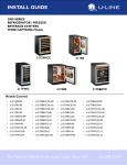
SURGICAL TECHNIQUE
Proudly distributed by
APEX Knee™ Surgical Navigation
with the PRAXIM Robotic Cutting Guide™
Independent Cuts - Measured Resection
™
APEX ROBOTIC
SURGICAL
TECHNOLOGY
TECHNIQUE
Congratulations!
You are about to embark on a computer automated (CAS) and navigated total knee
surgical technique that is truly cutting edge by integrating an automated interactive
cutting block, the Praxim Robotic Cutting Guide.
You will be performing a navigated imageless total knee replacement. The APEX
Knee™ implants will be individualized with regard to position, alignment and size
with an extreme level of CAS validated accuracy. In my experience this has led
to a well-balanced TKR with a history of no early failures due to malalignments,
improper sizing or malpositioning. CAS TKR has made me a better and more
accurate surgeon.
Jan Albert Koenig, MD
Dear User,
This guide is provided to aid in a surgical procedure and does not replace the system
and software user manual or medical and surgical judgment. Please carefully review
the full Instructions for Use before using this device, including the warnings and
recommendations contained therein.
The APEX Robotic Technology™ (A.R.T.) system includes many options that allow
the clinician to individualize the protocol based on his preferred surgical technique.
This guide includes guidelines, tips and information on one technique. Please contact
your sales representative or our customer support for more information on other
available options.
Indications for Use:
The TOTAL KNEE SURGETICS™ Navigation System with iBlock is intended for
use during stereotaxic surgery to aid the surgeon in locating anatomical structures and
aligning the endoprostheses with the anatomical structures. It is specifically indicated
for Total Knee Arthroplasty.
1
APEX ROBOTIC TECHNOLOGY™
OMNIlife science™ would like to thank Jan Albert Koenig, MD
for his assistance in editing this document.
2
TABLE OF CONTENTS
Table of Contents
3
Preoperative Planning
4
Navigation System
5
Operating Room Set-up
6
Starting the System
7
Customizing the Surgeon’s User Profile
9
Patient Information
10
Instrument Calibration
11
Praxim Robotic Cutting Guide Installation
16
Positioning of “T” and “F”
19
Anatomical Acquisitions
22
Pre-operative Pathology
32
Virtual Femoral Surgery
33
Femoral Cuts Navigation - Praxim Robotic Cutting Guide™
35
Virtual Tibial Surgery
43
Tibial Cut Navigation - NanoBlock™
44
Preparation of the Patella
47
Trial Reduction and Final Components Selection
48
Trial Alignment Validation
50
Final Bone Preparation
52
Final Component Implantation
53
Final Alignment Validation
57
Per-operative Report Recording
58
Symbols - Graphical Interface
59
Navigation Instrument List
60
APEX Knee™ Instrument List
62
3
APEX ROBOTIC TECHNOLOGY™
Pre-operative Planning
Individualized implant positioning,
size and alignment
Suggested Templating Method
High quality radiographs are extremely important for
precise preoperative planning.
Work from accurate radiographs. Full length AP and
lateral extremity roentgenograms should be obtained and
the mechanical and anatomic axes identified. The angle
of these axes is useful in establishing the plane of the
distal femoral resection and tibial resection. It is helpful
to draw the femoral and tibial resection lines on the films
as an intra-operative reference.
Radiographic templates are provided to permit
preoperative estimation of implant size. The templates
are overlaid on the x-ray films. It is recommended to
check the magnification of the radiographs in order to
choose the right size of the radiographic templates to be
used. The APEX system is also present in several digital
radiographic systems.
The size of the femoral component in the lateral view
is of particular importance since under sizing will result
in looseness in flexion as well as greater potential for
notching of the anterior femoral cortex. Over sizing can
create tightness in flexion and increase the potential for
increased excursion of the quadriceps mechanism.
The APEX Knee system permits the use of tibial inserts
one size higher or any size lower than the tibial tray
size. This allows the use of the tibial tray with the best
possible coverage of the tibial plateau with an insert that
best matches the femoral component. In all cases, the
numerical size of the tibial insert should match that of
the femoral component, including the “plus” sizes. For
example, a size 2 tibial insert should be used with a size 2
or size 2+ femoral component.
Notes: The APEX Knee system instrumentation is designed
to adapt to the surgical technique of any surgeon. To describe
this Surgical Technique, the preparation of the femur has been
chosen as the first step in the procedure.
4
SURGICAL TECHNIQUE
Navigation System
1
A.R.T.™ Station
The A.R.T. Station includes the following elements:
1. Optical camera
2. Panel PC with tactile screen
3. Praxim Robotic Cutting Guide Control Box
2
4. Drawer containing the foot pedal and power cord
3
4
Instrument Set
The Praxim Robotic Cutting Guide instrument set
contains all the instruments specific to navigation
that are required for use with the APEX Knee
Surgical Navigation application.
In addition, a portion of the OMNI APEX
standard instrument set will also be required,
including but not limited to, femur/tibia finishing
Instruments and trial implants.
Disposables and System Start Kit
The A.R.T. Disposables and System start kit
includes the following elements:
• One box of 20 disposable sterile markers
• One CD-ROM to record the navigation
report at the end of the surgery
• One software Start card
5
APEX ROBOTIC TECHNOLOGY™
Operating Room Set-up
Standard set-up
In the operating room, the navigation system can be installed on either side of the operated knee.
It is recommended that the system be set up on the opposite side of the patient from the surgeon.
The camera needs to be placed about 5 to 6 feet (1.5 to 1.8 meters) from the knee.
Set-up (A) for a Right Knee
Set-up (A) for a Left Knee
Alternative Set-up (B) with an External Screen
The system can be installed with an additional
external screen connected via VGA cable.
The addition of a second external monitor should
be in compliance with the individual hospital’s
Biomedical Department specifications.
The additional external screen is turned to the
surgeon whereas the panel pc tactile screen is
turned to the nurse for easy access to settings
during surgery.
6
SURGICAL TECHNIQUE
Starting the System
Plug the A.R.T. Station into an electrical outlet
using the power cord located on the right side,
inside the base of the system.
Start the A.R.T. Station using the green on/off
button located at the base of the system. The system
should emit audio tones to indicate that the camera
is powered and operational.
Connect the Praxim Robotic Cutting Guide
Control Box to USB port 0 of the Panel PC
using the USB cable.
Plug in the Praxim Robotic Cutting Guide Control
Box to an electrical outlet using its own power cord.
Turn on the Praxim Robotic Cutting Guide Control
Box using the on/off button located on the bottom
right. Two LED lights should illuminate to indicate
that the Control Box has powered on.
7
APEX ROBOTIC TECHNOLOGY™
Starting the System
When the PRAXIM™ Software Application screen
appears, insert the provided Total Knee Surgetics
OMNI APEX Start card in the appropriate slot
(marked SIM) on the side of the Panel PC to start
the software.
Select the flag corresponding to the desired
language and press the right arrow to start the
application.
After few seconds, the welcome step appears on the
screen.
Click on the blue arrow or step on the blue pedal to
proceed to the next step.
Notes: To move forward or backward in the workflow
touch the screen or click the pedal.
The blue arrow button or blue pedal advances
the screen.
The yellow arrow button or yellow pedal returns
to the previous screen.
8
SURGICAL TECHNIQUE
Individualizing the
Surgeon’s User Profile
Select an existing user on the touch screen then
press the blue button or blue pedal to set up the
surgical protocol.
To create a new user press the ‘ADD USER’ button
on the touch screen, type in the user name and press
‘SAVE’.
Click on the blue arrow or step on the blue
pedal to proceed to the next step.
Select the Surgical Technique corresponding to the
use of the Praxim Robotic Cutting Guide.
Select the NanoBlock™ and the Profile to be used
for this procedure:
- INDEPENDENT CUTS – The bone cuts will be
based on measured resection and leg alignment.
Click on the blue arrow or step on the blue
pedal to proceed to the next step.
Notes: It is possible to select another PROFILE and/
or to MODIFY OPTIONS. In this case please refer to
the Instruction for Use for “Total Knee Surgetics OMNI
APEX”.
9
APEX ROBOTIC TECHNOLOGY™
Patient Information
Enter the patient name, ID, and birth date
(DD/MM/YYYY) via the on-screen keyboard.
Choose the leg that is being operated on and
continue to the References and Camera set up.
The information entered on this page will be
recorded on the post-operative CD-ROM.
If you do not wish this information to appear, please
leave the fields blank.
Click on the blue arrow or step on the blue
pedal to proceed to the next step.
It may be necessary to wait a few minutes while the
system is loading the data for the surgery.
10
SURGICAL TECHNIQUE
Instrument Calibration
IMPORTANT
To improve operative efficiency these steps should be performed on the back table prior to beginning the surgery.
Attach 18 reflective markers on the navigation references:
• 3 on Femur – “F” reference (#0501-5020)
• 3 on Tibia – “T” reference (#0501-5030)
• 6 on Pointer – “P” reference (#0501-5000)
• 6 on Guide – “G” reference (#0501-5070)
The markers should ‘click’ into place to indicate proper
attachment. Take care not to damage the reflective surface
of the markers when pressing them into position.
Pointer Calibration
Calibrate the Pointer “P” (#0501-5000) by placing the tip
in the calibration cone on top of the “T” reference
(#0501-5030)and facing the markers towards the camera.
The letters “T” and “P” must appear in the field of visibility
of the camera. They also appear in green at the top of the
screen.
Step on the blue pedal to begin the calibration.
Rotate the Pointer “P” to face the other 3 markers towards
the camera. The tip of the “P” should stay in the calibration
cone of the “T”. Check the visibility of “T” and “P”.
Step on the blue pedal to finish the calibration.
Notes: To help maximize calibration accuracy of the pointer
“P”, do not apply force on the “P” and place it as shown on
pictures (perpendicular to the face). “P” and “T” should be in
the middle of the camera field of view during calibration.
11
APEX ROBOTIC TECHNOLOGY™
Instrument Calibration
Adjustment of the NanoBlock™
Screws to Zero Position
Adjust the initial position of each adjustment screw of the
NanoBlock (#4137-5000) using the provided NanoBlock
Initialization Socket (#4137-2050).
The screws are in the correct position when the machined
groove on the head of each screw appears in the center of
the window when the initialization socket is in contact with
the surface of the NanoBlock.
NanoBlock™ Calibration
Assemble the “G” reference (#0501-5070) by aligning
the three (3) holes on the Reattachable Fixation for “G”
(#4146-5000) to the three (3) pegs on the “G” reference and
tightening the thumb screw.
Use the push-release button on the “G” reference fixation to
attach it to the NanoBlock.
Note: Proper adjustment to zero position prior to Calibrating
the NanoBlock before each case will assure optimal accuracy and
cut validation. All calibration should be performed on the back
table prior to the start of surgery.
12
SURGICAL TECHNIQUE
Instrument Calibration
Calibrate the NanoBlock (#4137-5000) by placing the tip
of the Pointer “P” (#0501-5000) in each (4) calibration cone
located on the top surface.
Check the visibility of “P” and “G” references.
Step on the blue pedal to register each (4) cone.
Note: In order to aid in the calibration accuracy of the
NanoBlock, do not apply excessive force on the tip of the
“P” and use the same face of the “P” and “G” towards the
camera for all four cone acquisitions.
13
APEX ROBOTIC TECHNOLOGY™
Instrument Calibration
Cut Controller and Cut Controller /
OMNI Drill Calibration
Use the push button to attach the “G” reference (#05015070) to the Cut Controller (#4161-5100) using the
Reattachable Fixation for “G” (#4146-5000).
Calibrate the cut controller (#4161-5100) by placing the
tip of the Pointer “P” (#0501-5000) in each of four(4)
calibration cones located on its face.
Check the visibility of “P” and “G” references.
Step on the blue pedal to register each (4) cone.
14
SURGICAL TECHNIQUE
Instrument Calibration
Praxim Robotic Cutting Guide
Cutting Guide Calibration
Use the push button to attach the “G” reference (#05015070) to the Praxim Saw Guide - 1.27mm (#4146-5200)
using the Reattachable Fixation (#4146-5000).
Calibrate the cutting guide (#4146-5200) by placing the
tip of the Pointer “P” (#0501-5000) in each of four (4)
calibration cones located on its face.
Check the visibility of “P” and “G” references.
Step on the blue pedal to register each (4) cone.
INSTRUMENT CALIBRATION RECOMMENDATIONS:
- Do not push too hard on the pointer during calibration, so as not to cause deflection of
the tip of the pointer.
- Position the pointer as perpendicular as possible to the face of the
instrument where the cone is located during digitization.
- Make sure that the ball-tip of the pointer is completely seated inside the cone.
- Make sure that the instruments are in the center of the camera field of view
(depth and centering) during calibration.
- Use the same side of the pointer when digitizing each cone of one instrument.
15
APEX ROBOTIC TECHNOLOGY™
Praxim Robotic Cutting
Guide Installation
1
Motor
Insertion Guide
Enclosure Body
Insertion of the Praxim Robotic
Cutting Guide Motor Unit
To ensure sterility, the insertion of the Praxim Robotic
Cutting Guide motor unit in its sterile enclosure requires
two people, one sterile and one non sterile:
2
1. Sterile individual places the Praxim Robotic
Cutting Guide Motor Insertion Guide (#41448000) onto the Praxim Robotic Cutting Guide
Enclosure Body (#4144-7000).
Non sterile individual drops the Praxim Robotic
Cutting Guide Motor Unit (#4144-6000) into the
Praxim Robotic Cutting Guide™ Enclosure Body.
2. Non sterile individual removes the Praxim Robotic
Cutting Guide Insertion Guide.
3. Sterile individual closes the Praxim Robotic Cutting
Guide Enclosure Body with the Praxim Robotic
Cutting Guide Cover (#4144-4000) and locks it
securely with the screw.
Non sterile
Sterile
16
3
Cover
SURGICAL TECHNIQUE
Praxim Robotic Cutting
Guide Installation
Locking of the Axes
Tighten the central locking screws on both axes of the
Praxim Robotic Cutting Guide Enclosure Body (#41447000) with the H3.5 screwdriver (#9-144) until the axes
begin to turn.
Note: When tightening the locking screws discussed above, do
not overtighten the screws.
Locking of the Orientation Adjustment and
Cutting Guide Fixation Interfaces
Attach the Orientation Adjustment Interface (#4145-2000)
on the face of the dedicated axis with a H3.5 screwdriver
(#9-144).
Attach the Cutting Guide Fixation Interface (#4146-1000)
on the face of the other axis with the H3.5 screwdriver.
Note: Take care to properly align screws before tightening to
avoid stripping the threads.
17
APEX ROBOTIC TECHNOLOGY™
Praxim Robotic Cutting
Guide Installation
Connecting the Praxim Robotic Cutting
Guide to the Control Box
Keep the Praxim Robotic Cutting Guide and most of the
connecting cable on the operating table and hand off the
other end of the cable to a non-sterile person to connect
it to the Praxim Robotic Cutting Guide Control Box
attached to the A.R.T. station. The red dot on the connector
should align with the red dot on the connection port of the
Control Box.
Step on the blue pedal to proceed to the next step.
Note: Make two 30cm wide loops with the Praxim Robotic
Cutting Guide cord to prevent any accidental pulling of the
cable.
Draping Technique: Carefully place excess cable under the
sterile drape to avoid inadvertently pulling or stretching the
cable during surgery.
Step on the blue pedal to test the Praxim Robotic
Cutting Guide before proceeding to the next step.
18
SURGICAL TECHNIQUE
Positioning of “T” and “F”
Placement of the “T” reference
Place the first 3.2mm Bone Screw (#4148-1004 or
#4148-1005) approximately four fingers below the tibial
plateau using the Multi Diameter Quick Socket (#41482000).
The placement of the second screw can be done using the
Two Pin Universal Fixation (#4149-5000) as a drill guide.
For improved stability, leave at least one hole between the
two screws.
Secure the Two Pin Universal Fixation manually on the
two screws by tightening the thumbscrew. It is important
that the bone screws have solid bone fixation and the
Two Pin Universal Fixation is firmly clamped onto the
screws. Attach the “T” reference (#0501-5030) to the Two
Pin Universal Fixation using the Universal Reattachable
Joint Ø6.9mm Adaptor (#4154-5000), align the optical
markers with the sagittal plane of the tibia, and tighten the
thumbscrew on the adapter.
In the presence of soft bone, a 4.0 mm bone screw
(#4148-1001 or #4148-1002) is available to gain
additional stability.
19
APEX ROBOTIC TECHNOLOGY™
Positioning of “T” and “F”
Placement of the “F” reference and
Femur Bone Fixation Base
1. Place the Femur Bone Fixation Base (#4145-5100)
between the jaws of the Positioning Clamp for
Femur Bone Fixation Base (#4145-3100).
Close the clamp and engage the locking teeth.
2. Position the Femur Bone Fixation Base against
the medial aspect of the distal femur, with the wing
of the clamp in contact with the medial distal
condyle; the drill guide just anterior to the
attachment of the medial epicondyle.
3. Point the fixation base stem towards the femoral
head of the hip in the frontal and the sagittal plane.
4. Align the wing of the clamp in the axial plane with
the trans-epicondylar or posterior condylar axis.
This will align the pins with the femoral resections
in the sagittal plane.
5. Slide and rotate the stylus on the clamp so that
the tip is in contact with the center of the anterior
cortex, in the area of the implant apex. This will
position the screws posterior to the anterior
resection.
6. Taking into account the quality of bone and the
prosthesis to be used, select the appropriate position
and length of Praxim Cancellous Bone Screws
(#4145-5003 or #4145-5004). Using a power drill
equipped with a Multi Diameter Quick Socket
(#4148-2000), insert the Cancellous Bone Screws
by drilling them until they disengage from the
socket and are completely inserted into the Femur
Bone Fixation Base. Only a small portion of the
screw ends should be protruding out of the
fixation base.
7. Remove the clamp.
20
SURGICAL TECHNIQUE
Positioning of “T” and “F”
Tighten the fixation base with the H3.5 screwdriver
(#9-144).
Attach the “F” reference (#0501-5020) to the Fixation Base
with the 45°angled Reattachable Adaptor (#4154-5100)
and tight in position using the H3.5 screwdriver. Align the
optical markers of the femoral reference with the sagittal
plane of the femur.
Note: It is possible to replace the 45°angled Reattachable Adaptor
(#4154-5100) with the Universal Reattachable Joint Ø6.9mm
Adaptor (# 4154-5000).
IMPORTANT
Check that there will be no problem with line of sight to
the camera and ancillary instrumentation used through
range of motion of the femur and tibia.
Check visibility of “F” and “T” on the screen in maximum
flexion and in extension. Adjust the orientation of the
references as necessary and proceed.
Click on the blue arrow or step on the blue pedal
to proceed to the next step.
21
APEX ROBOTIC TECHNOLOGY™
Anatomical Acquisitions
Hip Center
Begin the hip center acquisition by stepping
on the blue pedal and then rotating the
femur. The diameter of rotation around the
femoral reference must be at least 15cm,
but the speed and direction of rotation
does not matter.
Note: Make sure the hip does not move, otherwise the
hip center will have to be reacquired.
Ankle Center
Place the Pointer “P” on the most distal point of the
medial malleolus.
Step on the blue pedal to record the
position of this point.
Place the Pointer “P” on the most distal point of the
lateral malleolus.
Step on the blue pedal to record the
position of this point.
Note: Except when Manual option is selected, the
system uses the middle of the lateral and medial
malleolus to determine the center of the ankle.
22
SURGICAL TECHNIQUE
Anatomical Acquisitions
Calibration of the Femur Bone
Fixation Base
Calibrate the Femur Bone Fixation Base (#41455100) by placing the tip of the pointer “P” in each
of three (3) calibration cones located on the top
surface.
Check the visibility of “P” and “F” references.
Step on the blue pedal to register each
(3) cone.
Note: If necessary it is possible to calibrate the Femur
Bone Fixation Base later in the procedure. To do so, hide
the pointer “P” and click on the blue pedal.
Femur Center
Place the pointer “P” on the anterior arch of the
distal femur to acquire the center of the femur.
Step on the blue pedal to record the
position of this point.
Note: The system will calculate the mechanical axis of
the femur based on the line joining the hip center and
center of the distal femur
23
APEX ROBOTIC TECHNOLOGY™
Anatomical Acquisitions
Medial Posterior Condyle –
Bone-Morphing™ Technology
Place the tip of the pointer “P” on the medial
posterior condyle.
Step on the blue pedal to start the
acquisition.
Glide or paint the tip of the “P” on the posterior
condyle until the green bar fills up. Focus on
acquiring a large surface area as opposed to
gathering many points in a small concentrated area.
It is important to keep “P” in constant contact with
the bone during morphing or point acquisition.
Note: This surface is used to determine the medial
posterior reference point.
Lateral Posterior Condyle –
Bone-Morphing Technology
Place the tip of the “P” on the lateral posterior
condyle.
Step on the blue pedal to start the
acquisition.
Glide or paint the tip of the “P” on the posterior
condyle until the green bar fills up maintaining
constant contact.
Note: This surface is used to determine the lateral
posterior reference point. Cover a surface as large as
possible in all directions.
24
SURGICAL TECHNIQUE
Anatomical Acquisitions
Medial Distal Condyle –
Bone-Morphing Technology
Place the tip of the “P” on the medial distal condyle.
Step on the blue pedal to start the
acquisition.
Glide or paint the tip of the “P” on the distal
condyle until the green bar fills up maintaining
constant contact.
Note: This surface is used to determine the medial distal
reference point which defines the distal resection height.
Cover a surface as large as possible in all directions.
Medial Side –
Bone-Morphing Technology
Place the tip of the “P” on the medial side of the
femur about 10mm from the distal medial surface
Step on the blue pedal to start the
acquisition.
Glide or paint the tip of the “P” on the side of
the femur until the green bar fills up maintaining
constant contact.
Note: This surface is used to visualize the ML size
of the femur. Cover as large a surface as possible in all
directions.
25
APEX ROBOTIC TECHNOLOGY™
Anatomical Acquisitions
Lateral Distal Condyle –
Bone-Morphing Technology
Place the tip of the “P” on the lateral distal
condyle.
Step on the blue pedal to start the
acquisition.
Glide or paint the tip of the “P” on the distal
condyle until the green bar fills up maintaining
constant contact.
Note: This surface is used to determine the lateral distal
reference point. Cover a surface as large as possible in all
directions.
Lateral Side –
Bone-Morphing Technology
Place the tip of the “P” on the lateral side of the
femur 10mm from the distal lateral surface.
Step on the blue pedal to start the
acquisition.
Glide or paint the tip of the “P” on the lateral
side of the distal femur until the green bar fills up
maintaining constant contact.
Note: This surface is used to visualize the ML size of
the femur. Paint as large a surface as possible in all
directions.
26
SURGICAL TECHNIQUE
Anatomical Acquisitions
Anterior Femoral Cortex –
Bone-Morphing Technology
Place the tip of the “P” on the anterior cortex.
Step on the blue pedal to start the
acquisition.
Glide the tip of the “P” “on the entire anterior
cortex including the area where the implant will rest
maintaining constant contact. The acquisition will
complete when the green bar fills up.
Note: This surface will allow checking for possible
notching when navigating the anterior femoral cut. The
surface that will be potentially covered by the implant
will need to be acquired, especially the most proximal
and most lateral parts, to safeguard against notching the
femur.
Bone-Morphing Validation
Place the pointer “P” on the anatomical landmarks
of the bone including the anterior cortex and distal
and posterior condyles.
The value indicated on the screen below the bone
model represents the distance between the pointer
and the bone model. Check that the distance is less
than or equal to 1mm in these key areas. (see Note:)
Step on the blue pedal to validate the
generated 3D model.
Note: This step allows checking the accuracy of the
3D model generated by the system. If the increment of
the validation measurement exceeds 1mm, step on the
yellow pedal to go back one-step in the procedure and
add points to the Bone Morphing data using the blue
pedal. Start and stop complementary acquisitions by
stepping on the blue pedal. During acquisition the “P”
must be in constant contact with the bone.
27
APEX ROBOTIC TECHNOLOGY™
Anatomical Acquisitions
Tibia Center
Place the tip of the “P” on the tibial eminence.
Step on the blue pedal to record the
position of this point.
Note: The system will calculate the tibial mechanical
axis based on the line joining the center of tibia and
ankle center.
Tibial Rotation Reference
Place the tip of the “P” on the medial 1/3 side of the
anterior tibial tuberosity.
The rotational axis of the tibia will be defined using
this point coupled with the tibial center.
Step on the blue pedal to record the
position of this point.
Hint: This reference needs to be taken carefully as
it defines the direction of the slope for positioning
the implant.
28
SURGICAL TECHNIQUE
Anatomical Acquisitions
Medial Tibial Cut Height Reference
Place the tip of the “P” on the medial cutting height
reference.
Step on the blue pedal to record the
position of this point.
Lateral Tibial Cut Height Reference
Place the tip of the “P” on the lateral cutting height
reference.
Step on the blue pedal to record the
position of this point.
Note: The highest of these two cut height references is
used by default to set the tibial resection level at 10mm.
29
APEX ROBOTIC TECHNOLOGY™
Anatomical Acquisitions
Medial Tibial Side –
Bone-Morphing Technology
Place the tip of the “P” on the medial border of the
tibial plateau.
Step on the blue pedal to start the
acquisition.
Glide or paint the tip of the “P” until the green bar
fills up maintaining constant contact.
Note: This surface is used to determine the size and
centering of the implant. Cover a surface as large as
possible in all directions.
Lateral Tibial Side –
Bone-Morphing Technology
Place the tip of the “P” on the lateral border of the
tibial plateau.
Step on the blue pedal to start the
acquisition.
Glide or paint the tip of the “P” until the green bar
fills up maintaining constant contact.
Note: This surface is used to determine the size and
centering of the implant. Cover a surface as large as
possible in all directions.
30
SURGICAL TECHNIQUE
Anatomical Acquisitions
Anterior Tibial Surface –
Bone-Morphing Technology
BONE-MORPHING RECOMMENDATIONS:
It is important not to include osteophytes during
Bone Morphing acquisitions. Removal of osteophytes
before starting the Bone Morphing surface
acquisitions process is recommended.
Place the tip of the “P” on the anterior part of the
tibial plateau.
Step on the blue pedal to start the
acquisition.
Glide or paint the tip of the “P” until the green bar
fills up maintaining constant contact.
Note: This surface is used to determine the anterior
position of the implant. Cover a surface as large as
possible in all directions.
Bone-Morphing Validation
Place the pointer “P” on the anatomical landmarks
of the bone, such as the anterior cortex and the
medial and lateral borders of the proximal tibia.
The value indicated on the screen below the bone
model represents the distance between the pointer
and the bone model. Check that the distance is less
than or equal to 1mm in these key areas. (see Note:)
Step on the blue pedal to validate the
generated 3D model.
Note: This step allows checking the accuracy of the
3D model generated by the system. If the increment of
the validation measurement exceeds 1mm, step on the
yellow pedal to go back one-step in the procedure and
add points to the Bone-Morphing data using the blue
pedal. Start and stop complementary acquisitions by
stepping on the blue pedal. During acquisition the “P”
must be in constant contact with the bone.
31
APEX ROBOTIC TECHNOLOGY™
Pre-operative Pathology
The initial pathological varus/valgus angle and the
maximum flexion and extension can be measured
at this stage prior to making any bone cuts. This
information can then be compared to post-operative
alignment results using the same test.
Flex and extend the leg to check for any initial
flexion deformity and the maximum flexion.
Optionally, the screenshot button can be pressed to
save the information for different positions.
The leg position at the time of the validation will be
automatically saved in the post-operative report.
Step on the blue pedal with the leg in
extension to record the initial alignment
and proceed to the next step.
32
SURGICAL TECHNIQUE
Virtual Femoral Surgery
1. Select the parameter
to be adjusted.
2. . Change value.
Distal Resections (mm)
Anterior Notching (mm)
Varus / Valgus (°)
Posterior Resections (mm)
Flexion (mm)
Axial Rotation (°)
33
APEX ROBOTIC TECHNOLOGY™
Virtual Femoral Surgery
Check the proposed cuts and size of the femoral
implant. The surgeon may adjust the size and
position of the implant specific to every patient
based on the Bone-Morphing model previously
generated and is now displayed on the monitor.
Use the X crossed implant button to hide
the femoral component and visualize cuts
on the 3D bone model.
The medial/lateral sizing should be carefully
checked. Often, especially in female patients, the
ideal M/L size may be smaller than the A/P size. If
the proper A/P size is too wide for a size 3 or size 4
femur, a “plus” size femoral component may be used.
For example, a 2+ femoral component has the same
A/P box cuts as a size 3 but a smaller ML width.
Therefore there is no need to downsize the femur to
compensate for potential M/L overhang.
If necessary, modify the parameters of the implant
position, using the panel on the left.
Step on the blue pedal to validate the
position of the femoral implant and
proceed to the next step.
Note: Standard cuts proposed with this software
are equal to the thickness of the femoral component
(example: 9mm on distal condyles). The preferred
method of establishing rotation is to externally rotate
the femoral component 3° with respect to the posterior
condyles. However, the surgeon has the option of
changing the default value in the surgeon profile or
adjusting the amount of rotation during this step
in the surgery.
34
SURGICAL TECHNIQUE
Femoral Cut Navigation Praxim Robotic Cutting
Guide
Installation of the Praxim Robotic
Cutting Guide
Mount the Praxim Robotic Cutting Guide onto
the Femur Bone Fixation Base (#4145-5100) by
inserting the centering post of the Orientation
Adjustment Interface (#4145-2000) piece into
the outermost hole on the base (i.e. the hole that
is the furthest away from the bone). Insert the
sliding (loose) screw into the innermost hole of
the base (i.e. the hole that is the closest to the
bone). Finger tighten the screws with the H3.5
screwdriver (#9-144).
Insert the Praxim Saw Guide - 1.27mm
(#4146-5200) mounted with the “G” reference
(#0501-5070) in the dove tail groove.
Lock the saw guide in a position just far enough
from the bone to allow movement of the Praxim
Robotic Cutting Guide around the femur.
Praxim Robotic Cutting Guide
Rotation Adjustments
Note: At this stage for increased accuracy it is advised to
place the guide in the anterior cut position.
Remember – The Tortoise Beats the Hare.
Moving the Praxim Robotic Cutting Guide slowly
in the suggested plane will make aligning the varus/
valgus position and axial rotation to acceptable
values easier.
35
APEX ROBOTIC TECHNOLOGY™
Femoral Cut Navigation Praxim Robotic Cutting
Guide
Loosen one screw and follow the direction shown
in the top third of the screen. Lock the screw when
it becomes green. Go slowly as the tendency is to
overshoot and there is a slight lag in the image
motion.
Repeat the same procedure for the second screw.
Once the two screws become green, the lines also
become green and the target alignment position is
reached.
Step on the blue pedal to record the desired
alignment and proceed to the next step.
36
SURGICAL TECHNIQUE
Femoral Cut Navigation Praxim Robotic Cutting
Guide
Praxim Robotic Cutting Guide
Calibration
Place the Praxim Saw Guide - 1.27mm
(#4146-5200) in the most posterior position
possible by rotating the two Praxim Robotic
Cutting Guide axes.
Make sure that the Praxim Saw Guide - 1.27mm is
far enough from the bone and is tightly locked into
position.
Note: The Praxim Saw Guide - 1.27mm must be
engaged over the entire length of the dove tail groove
to guarantee accuracy of the calibration.
Step and Hold down the blue pedal
throughout the entire calibration process
of the Praxim Robotic Cutting Guide.
The acquisition will complete when the
green bar fills up and the Praxim Robotic
Cutting Guide will position itself for the
first cut and then release the pedal.
Note: There is a slight lag before motion begins as the
data points are set.
During the calibration process, the Praxim Robotic
Cutting Guide will automatically move around
the femur.
IMPORTANT
The Praxim Saw Guide - 1.27mm (#4146-5200) can be slid towards the bone to reduce skiving of the saw blade.
Do not move the cutting guide all the way down into contact with the bone because this can cause deflection of the
cutting guide. After making each cut, it is strongly recommended to unlock and pull back the saw guide to avoid
contact with bone as the Praxim Robotic Cutting Guide changes position for the next cut.
Note: The “G” reference can be removed from the Praxim Saw Guide - 1.27mm after the calibration process is complete.
37
APEX ROBOTIC TECHNOLOGY™
Femoral Cut Navigation Praxim Robotic Cutting
Guide
Femoral Distal Cut
Cut the femur using a 1.27mm thick saw blade.
Note: The distal cut can be adjusted at this point. Use
the touchscreen to adjust the distal cut if desired and
then step and hold on blue pedal to move the Praxim
Robotic Cutting Guide. Recut can be required in case of
flexion contracture or to gain more knee extension.
After cutting, it is strongly recommended to unlock
and pull back the saw guide to avoid contact with
bone as the Praxim Robotic Cutting Guide changes
position for the next cut.
Step and hold down the blue pedal until
the Praxim Robotic Cutting Guide is
locked in position to move to next cut.
38
SURGICAL TECHNIQUE
Femoral Cut Navigation Praxim Robotic Cutting
Guide
Femoral Anterior Cut
Cut the femur using a 1.27mm thick saw blade.
Note: The anterior cut height can be adjusted at this
point. Use the touchscreen to adjust the anterior cut if
desired and then step and hold on blue pedal to move the
Praxim Robotic Cutting Guide. Recut can be required
to avoid trochlea over stuffing.
After cutting, it is strongly recommended to unlock
and pull back the saw guide to avoid contact with
bone as the Praxim Robotic Cutting Guide™
changes position for the next cut.
Step and hold down the blue pedal until
the Praxim Robotic Cutting Guide is
locked in position to move to next cut.
39
APEX ROBOTIC TECHNOLOGY™
Femoral Cut Navigation Praxim Robotic Cutting
Guide
Femoral Posterior Cut
Cut the femur using a 1.27mm thick saw blade.
Step and hold down the blue pedal until
the Praxim Robotic Cutting Guide is
locked in position to move to next cut.
Femoral Anterior Chamfer Cut
Cut the femur using a 1.27mm thick saw blade.
Step and hold down the blue pedal until
the Praxim Robotic Cutting Guide is
locked in position to move to next cut.
40
SURGICAL TECHNIQUE
Femoral Cut Navigation Praxim Robotic Cutting
Guide
Femoral Posterior Chamfer Cut
Cut the femur using a 1.27mm thick saw blade.
Step on the blue pedal to proceed to
the next step.
Distal Cut Validation
Place the “G” (#0501-5070) equipped with the Cut
Controller (#4161-5100) flat on the performed
distal cut to check the final position of this cut.
Step on the blue pedal to record the
distal cut and proceed to the next step.
Note: The cuts can be checked either after each cut or
when all cuts have been performed depending on the
chosen option.
41
APEX ROBOTIC TECHNOLOGY™
Femoral Cut Navigation Praxim Robotic Cutting
Guide
Anterior Cut Validation
Place the “G” (#0501-5070) equipped with the Cut
Controller (#4161-5100) flat on the performed
anterior cut to check the final position of this cut.
Step on the blue pedal to record the
distal cut and proceed to the next step.
Note: It is important to carefully validate the femoral
anterior cut as this information will be used by the
system to calculate position of the implant for final
alignment. Alternatively, cut validation can be
performed using the Cut Controller / OMNI Drill
Guide (#4161-5400).
Once all the cuts have been completed and
validated, remove the Praxim Robotic Cutting
Guide from its fixation base by unscrewing the
inner screw using the H3.5 screwdriver (#9-144).
Proceed to the next step.
42
SURGICAL TECHNIQUE
Virtual Tibial Surgery
1. Select the parameter
to be adjusted.
2. . Change value.
Resections (mm)
AP Position
Varus / Valgus (°)
Slope (°)
Axial Rotation (°)
Check the proposed cut and the size of the tibial implant. In the default profile, the software measures resection
depth from the least affected side of the tibial plateau. This will produce a 10mm resection. If you choose to
measure resection depth from the most affected side of the tibial plateau, you should modify the corresponding
parameter or adapt your user profile to use the most affected side automatically. We recommend 2mm below
the most effected side to start. If necessary, modify the parameters of the implant positioning using the panel on
the left.
Step on the blue pedal to validate the position of the tibial implant and proceed to the next step.
43
APEX ROBOTIC TECHNOLOGY™
Tibial Cut Navigation NanoBlock
Hint: The NanoBlock (#4137-5000) must be set to neutral
position using the NanoBlock Initialization Socket (#41372050) before navigating the tibial cut.
Manual Adjustment
Manually adjust the position of the NanoBlock equipped
with the “G” (#0501-5070) until the cutting lines become
blue.
Red cutting lines indicate that the NanoBlock is too far
from the target line and must not be fixed in this position.
Fixation of the NanoBlock
When the cutting line is blue fix the NanoBlock to the tibia
with 2 or 3 Ø3.2mm Pins (#4148-1004 or #4148-1005)
using the Multi Diameter Quick Socket (#4148-2000).
Always start with the center hole as this eases adjustability by
providing a hinge point. The two outer holes are converging.
Depending on bone quality use two or three pins to achieve
stability.
44
SURGICAL TECHNIQUE
Tibial Cut Navigation NanoBlock
Navigated Adjustment
Adjust each of the three (3) NanoBlock screws using the H3.5
Screwdriver (#9-144) following the directions on the screen.
In the example above, the yellow screw needs to be turned
clockwise.
Once all the screws are green the final position is reached.
Place the NanoBlock Screw Head Stabilizer (#4137-5051)
onto all 3 screws.
Note: The tibial cut height can be adjusted at this point. Use the
touchscreen to adjust the cut if desired and then adjust each of
the 3 NanoBlock screws following the directions on the screen.
Step on the blue pedal to record the position
of the NanoBlock and proceed to the next step.
45
APEX ROBOTIC TECHNOLOGY™
Tibial Cut Navigation NanoBlock™
Cut
For easier access, remove the “G” from the NanoBlock
using the push-button on the reproducible fixation.
After the preliminary cut you may remove the center pin to
complete the cut, if necessary.
For the resection, is important to use an oscillating saw
blade of 0.050in or 1.27mm which matches the width of
the slot to in order to achieve a precise cut.
Note: If not using the NanoBlock Stabilizer (#4137-5050),
monitor the position of the three (3) positioning screws during
the cut because when subjected to strong vibrations, one or more
screws may turn. If more than ½ of a rotation occurs on any
screw, go back to the tibial cut navigation step to check and
readjust the NanoBlock into position.
Tibial Cut Validation
Place the “G” reference (#0501-5070) equipped with the
Cut Controller (#4161-5100) flat on the cut.
If necessary, refine the cut and recheck.
Alternatively, cut validation can be performed using the
Cut Controller / OMNI Drill Guide (#4161-5400).
Step on the blue pedal to record the final cut and
proceed to the next step.
46
SURGICAL TECHNIQUE
Preparation of the Patella
Patella Sizing
Patella thickness is measured using the Patella Caliper
(#KS-99250). The thickness of the patellar component in
the APEX Knee System is either 8 or 10 mm.
Note: It is recommended that the thickness of the patella after
resection be at least, 12mm to avoid excessive weakening of the
patella.
Also, the patella diameter is measured using the Patella
Reamer Drill Guide Foot (#WS-40001). The patellar
component diameters in the APEX Knee System are:
29, 32, 35 and 38mm.
Patella Resection
The Patella Resection Guide (#WS-40071) for the APEX
Knee System provides accurate, repeatable measurement of
patella resection. As the patella is clamped in the jaws of
the Resection Guide, the amount of resection is read from
the stylus. Swing the stylus to be perpendicular to the body
of the patella. The stylus can be moved up and down and
calibration marks read to set the desired resection.
The patella clamp saw capture slots accommodate a
0.050in. (1.27mm) saw blade.
Drill Pegs Holes
The holes for the 3 pegs on the patella are prepared using
the Patella Reamer Handle Assembly (#WS-40015) with
Drill Guide Foot (#WS-40001) loaded and the Patella Post
Drill (#KS-99210). Size is read from the concentric rings
on the bushing. The hole pattern is the same for all size
patella.
Note: The patella post drill is grey to avoid confusion with
femoral lug drill, which is black.
47
APEX ROBOTIC TECHNOLOGY™
Trial Reduction and Final
Component Selection
Surgeon preferences vary concerning the sequence of
implant placement. The APEX Knee System does not
require that a specific implant placement sequence be
followed. To describe this surgical technique, these are the
steps to follow.
Note: Additionally, Flexion/Extension Spacers (#KS-29510
to KS-29516) are available, but not included, to check the
flexion-extension alignment and ligament balance previously
to the use of the trial components.
Trial Femoral Component Placement
The chosen trial femoral component is placed on the cut
femur using the Femoral Inserter (#KS-61108).
Use the Femoral Inserter to guide the femoral component
into position and to avoid malpositioning or damage to the
femoral cuts.
Final seating of the femoral trial should be completed using
the Femoral Impactor Pad (#WS-10151) and the Impactor
Handle (#710300).
Note: It is recommended not to drill the holes for the femoral
component pegs until final trial reduction and a check of patella
tracking has been completed in case adjustment of the ML
position of the femoral component is required.
48
SURGICAL TECHNIQUE
Trial Reduction and Final
Component Selection
Trial Tibial Tray Placement
Once the correct alignment of the components has been
established, the Trial Tibial Tray (#WS-2111 to WS-2116,
L&R) of the selected size is placed using the Universal
Handle (#WS-30071) and fixed in position with two of the
provided headed fixation pins (#800100) inserted through
the pin holes in the trial tray.
To aid in positioning the final implant during insertion, it is
helpful to make two marks on the tibia on either side of the
Universal Handle attachment point on the tibial tray trial.
Cruciate Retaining and Cruciate Sacrificing
Tibial Insert Trial Placement
A CR Congruent Tibial Trial Insert of the same size as the
chosen Trial Femoral Component is placed on the Tibial
Tray Trial using the Trial Forceps (#KS-39000).
When the posterior cruciate ligament has been sacrificed or
has compromised function, the UC Ultra Congruent Tibial
Insert Trial should be used in place of the CR Tibial Insert
Trial.
Trial Patella Component Placement
The chosen Trial Patella Component (#KS-40298 to
KS-40388) is placed into the holes previously drilled
in the patella by using the Insert Trial Forceps.
49
APEX ROBOTIC TECHNOLOGY™
Trial Alignment Validation
Alignment Validation
After the trial components are inserted, adjust on
the screen the size of the tibial implant and insert
thickness that are used and check leg alignment.
Stability Validation
Knee extension and flexion stability must be
checked.
Full extension should be possible with the trial
components in place. Extension stability should be
checked with the knee flexed a few degrees to relax
the posterior capsule.
Flexion stability should be checked with the knee
in a flexion angle of 90º. Appropriate stability has
been achieved when the medial and lateral opening
indicated on the screen is similar to a healthy knee
when tension is applied in both valgus and varus
positions.
Hint: If desired, press on the screen shot button at any
time to save a picture in the pre-operative report.
Flexion Extension Validation
With the trials in place, it should be possible
to completely straighten the leg without the
application of any force. To check flexion the
surgeon should elevate the thigh and allow gravity
to flex the leg.
50
SURGICAL TECHNIQUE
Trial Alignment Validation
Patellar Tracking Slide Validation
During the flexion extension check the patella
should move smoothly within the patellar groove
with little or no pressure on its lateral border and
without the need to be medially stabilized.
If lateral subluxation should be present, the lateral
retinaculum may be released.
Note: The APEX knee system has been specifically
designed to reduce the need for lateral release for patella
stability.
Note: The same screen can be used to also check the
final implants stability.
Readjustments
Beginning with the 10mm Trial Tibial Insert,
ligamentous balance in both flexion and extension
is evaluated. In most cases, it is desirable that the
flexion and extension gaps be equal.
To modify the height of Trial Tibial Insert displayed
on the screen, select INSERT THICKNESS and
press + or – button.
If the flexion and extension gaps are not balanced, it
may be necessary to adjust the tibial and/or femoral
resection level. To modify the tibial resection or
femoral distal resection, press the corresponding
button on the left panel on the screen.
51
APEX ROBOTIC TECHNOLOGY™
Final Bone Preparation
The APEX Knee bone preparation system does not
require a specific implantation sequence.
The following steps describe the process of
preparing the bone for implanting the components:
Femoral Bone Preparation
For a CR Trial Femoral Component (#KS1410 to KS-1460 L&R) and after developing a
satisfactory trial reduction, the holes for the final
femoral component are made with the Femoral
Post Drill (#WS-10130) which passes through the
corresponding distal orifices of the Trial Femoral
Component.
Tibial Bone Preparation
With the Trial Tibial Tray fixed in position the bone
bed can be prepared to accept the tibial keel.
The appropriate size Tibial Keel Broach (#WS20124 to WS-20126) is attached to the Tibial
Punch Guide (#WS-20123) by pressing its shaft
button and is released once the broach is attached.
With the punch handle in the raised position, place
the Tibial Punch Guide on the Tibial Tray. Assure
that the face of the punch guide is flat against the
tibial trial. Impact the proximal strike plate with
mallet blows until the Tibial Keel Broach is fully
seated on the tibial tray trial.
Once the broach is fully seated, retract the guide by
hitting the handle in the reverse direction with the
mallet.
52
SURGICAL TECHNIQUE
Final Component
Implantation
The APEX Knee system does not require a specific
implantation sequence.
The following steps describe the implantation
process of implanting the components:
All trial components and resection surface tissue
debris should be removed.
It is recommended that thorough cleaning of all
bone surfaces and soft tissues be performed using
pulse lavage.
Tibial Baseplate Implantation
If a Cemented tibial tray is to be implanted, the
cement should be mixed and placed on both the
resected tibial surface and the tibial tray base by
hand or with a syringe. The tray should be placed
in the correct orientation following the previously
defined steps and be fully seated by using the Tibial
Tray Impactor Pad (#WS-20151) and the Impactor
Handle (#710300).
All excess cement should be cleaned from all
of the edges of the tibial component, starting at
the posterior surfaces, moving towards the sides and
to the anterior surfaces.
Uncemented (porous coated) tibial trays are inserted
and impacted without cement.
Note: This technique shows the implantation
of the tibial baseplate separately from the tibial insert.
The Tibial insert and tibial tray can also be implanted
as an assembled unit using instrument #KS-70023
(special order required).
53
APEX ROBOTIC TECHNOLOGY™
Final Component
Implantation
Femoral component implantation
The APEX Knee system includes cemented and
non-cemented femoral components.
When implanting a cemented component, a layer
of cement should be applied to the resected surfaces
of the femur and to the backside of the femoral
component.
Note: To avoid excessive posterior extrusion of cement
a posterior excessive cement, the quantity of cement
applied to posterior condyles of the femoral component
should be limited.
Final insertion of the femoral component should
be performed using the Femoral Inserter (#KS61108). Once the component positioning has been
confirmed, final seating should be performed using
the Femoral Impactor Pad (#WS-10151) and the
Impactor Handle (#710300).
If cement has been used, any excess cement should
be cleaned from the prosthesis edges. The implant
surface should be meticulously free of cement or
other debris.
If cement has been used, it is recommended that
as soon as the femoral and tibial components have
been seated, a trial tibial insert of the same size as
the femoral component be placed on the tibial tray.
The knee should then be brought into full extension
and held in position to pressurize the cement as
it cures. Any additional cement that is extruded
during cement compression should be removed at
this time.
Once the cement has hardened, the knee can be
brought back into flexion and the tibial trial is
removed.
54
SURGICAL TECHNIQUE
Final Component
Implantation
Tibial Insert Implantation
All extraneous cement must be removed from
the borders of the tibial tray. The surface of the
tibial tray should be meticulously cleaned prior to
placement of the tibial insert.
The tibial insert slides onto the tibial tray in the
anterior/posterior direction. The rails on the tibial
tray engage the grooves on the bottom of the tibial
trial.
Note: The APEX Knee system requires that the tibial
insert size match the femoral implant size. Tibial inserts
of one size larger, same size or any size smaller than
the tibial tray can be used. This permits selection of the
tibial insert that best matches patient anatomy while
assuring that the tibial insert always matches the femur
for optimum congruency, stability and wear resistance.
55
APEX ROBOTIC TECHNOLOGY™
Final Component
Implantation
Retaining Bolt Implantation
The Insert Retaining Bolt is threaded into the tibial
baseplate. If the retaining bolt does not thread
easily into the hole, first check that the tibial insert
has been completely pushed onto tibial baseplate.
Also check for debris that may be obstructing the
insertion of the bolt.
Note: Final tightening of the insert bolt should be
performed after the patella has been prepared, the
cement has hardened and a final inspection for excess
cement or debris is complete.
Patellar Component Implantation
The patella surface and the back of the patella
component should be coated with cement. The
patella component is then attached to the patella.
The Patella Reamer Clamp Foot Assembly
(#WS-40020) is then attached to the Patella
Reamer Handle Assembly (#WS-40015) and both
are used to compress the patella component firmly
onto the patella.
Note: Care must be taken to avoid excessive compression
as this may damage the patella.
Excess cement should be removed.
Final Tightening of Retaining Bolt
Once the cement has hardened and the tibial tray is
inspected one last time for excess cement and debris,
the final tightening of the tibial baseplate retaining
bolt is performed. With the knee in flexion, the
Torque Wrench (#KS-31000) is used to achieve the
final tightening of the bolt.
Note: Turn the driver until the arrow reaches the first
calibration line (60 in-lb). Take care not to tighten to
the 100 in-lb line.
56
SURGICAL TECHNIQUE
Final Alignment Validation
A final check should be performed prior to closure.
Any remaining excess cement should be removed.
Final assessment of alignment, stability, range of
motion and patella tracking should be performed.
Press on the screenshot button, if desired, at any
time to save a picture in the post-operative report.
Step on the blue pedal to record the final
alignment and proceed to report recording.
The final varus/valgus angle and the maximum
flexion and extension can be measured
at this stage. This information can then be
compared to pre-operative alignment results
using the same test.
Flex and extend the leg to check for any initial
flexion deformity and the maximum flexion.
Optionally, the screenshot button can be pressed
to save the information for different positions.
The leg position at the time of the validation will
be automatically saved in the post-operative report.
Step on the blue pedal with the leg in
extension to record the final alignment
and proceed to closure.
Closure
Closure is performed according to Surgeon
preference.
57
APEX ROBOTIC TECHNOLOGY™
Pre-operative Report
Recording
To record the navigation report on CD-ROM:
Click on the red cross located on the top
right of the screen and follow the
instructions on the screen.
58
SYMBOLS - GRAPHICAL INTERFACE
PLANNING AND NAVIGATION - FEMUR
Distal femoral cut height, medial and
lateral side (mm)
Distal cut Varus / Valgus angle (degrees)
Measure of antero-posterior alignment,
referenced off the anterior surface (mm)
Flexion angle (degrees)
Measure of antero-posterior alignment,
referenced off the posterior surface (mm)
Measure of axial rotation, referenced
off the epicondyles (degrees)
Measure of most anterior point of the
implant (apex), referenced off the anterior
cortical (mm)
Measure of axial rotation, referenced
off the posterior condyles (degrees)
Medio-lateral centering of the
implant (mm)
Measure of axial rotation, referenced
off the Whiteside line (degrees)
Antero-posterior offset, distance (mm)
Angular offset (mm)
Femoral distal cut Varus / Valgus angle
referenced off the tibial cut measured
Femoral posterior cut axial rotation angle
referenced off the tibial cut measured
PLANNING AND NAVIGATION - TIBIA
Anterior positioning of the tibial
implant using the anterior cortex
as reference (mm)
Slope angle in the tibial cut (degrees)
Tibial resection height (mm)
Axial rotation ref ATT
Tibial plateau resection height
medial and lateral (mm)
Axial rotation ref tibial plateaus
Varus / Valgus angle in the tibial
cut (degrees)
Axial rotation ref pointer axis
GLOBAL VALUES
Accuracy measure between the
pointer and the bone (mm)
Flexion measure (degrees)
Accuracy measure between the
pointer and the tibia (mm)
Angle measure when the leg is in the
hyper-extension (degrees)
Accuracy measure between the
pointer and the femur (mm)
Angle measure when the leg is in the
hyper-flexsion (degrees)
Hip-Knee-Ankle alignment measure in
the frontal plane of the leg (degrees)
59
INSTRUMENT LIST - NAVIGATION
DESCRIPTION
PRODUCT NUMBER
0501-5000
POINTER - << P >> REFERENCE
0501-5020
FEMUR - << F >> REFERENCE
0501-5030
TIBIA - << T >> REFERENCE
0501-5070
GUIDE - << G >> REFERENCE
4148-2000
MULTI DIAMETER QUICK SOCKET
4148-1001 / 4148-1002
DIAGRAM
SELF TAPPING / SELF DRILLING BONE SCREWS
FOR “T” OR “F” REFERENCE
(Ø4MM, LENGTH 120MM, 150MM)
4149-5000
TWO PIN UNIVERSAL FIXATION
4154-5000
UNIVERSAL REATTACHABLE JOINT Ø6.9MM
ADAPTOR
4161-5100
CUT CONTROLLER WITH REATTACHABLE
FIXATION INTERFACE
4161-5400
DRILL GUIDE OMNI APEX W/ REATTACHABLE
FIXATION INTERFACE
4137-5000
NANOBLOCK
4137-2050
NANOBLOCK INITIALIZATION SOCKET
4146-5000
REATTACHABLE FIXATION FOR “G”
9-144
4148-1005
ALLEN (HEX) KEY 3.5MM
SELF-TAPPING AND SELF-DRILLING BONE SCREW
(Ø3.3MM, L110MM, THREAD 40MM)
60
INSTRUMENT LIST - NAVIGATION
PRODUCT NUMBER
DESCRIPTION
DIAGRAM
4145-5100
FEMUR BONE FIXATION BASE
4145-1030
Ø6 X Ø4 ARTICULATED CONNECTOR
4154-5100
45° ANGLED REATTACHABLE ADAPTOR
4145-3100
POSITIONING CLAMP - FEMUR BONE FIX BASE
4145-2000
ORIENTATION ADJUSTMENT INTERFACE
4146-1000
CUTTING GUIDE FIXATION INTERFACE
4144-4000
PRAXIM ROBOTIC CUTTING GUIDE - COVER
4144-7000
PRAXIM ROBOTIC CUTTING GUIDE - ENCLOSURE
4144-8000
PRAXIM ROBOTIC CUTTING GUIDE INSERTION GUIDE
4146-5200
PRAXIM SAW GUIDE 1.27MM - SHORT
4146-5300
PRAXIM SAW GUIDE 1.27MM - SAFETY MODE
4145-5003
CANCELLOUS BONE SCREWS Ø5.5MM X 50MM
4145-5004
CANCELLOUS BONE SCREWS Ø5.5MM X 70MM
4137-5051
NANOBLOCK SCREW HEAD STABILIZER
PKX-5113-02
TOTAL KNEE SURGETICS OMNI APEX GREEN KIT
(DISPOSABLES)
61
INSTRUMENT LIST - APEX KNEE™
DESCRIPTION
PRODUCT NUMBER
WS-20123
TIBIAL PUNCH GUIDE
WS-20124
TIBIAL PUNCH DART SIZE 1/2
WS-20125
TIBIAL PUNCH DART SIZE 3/4
WS-20126
TIBIAL PUNCH DART SIZE 5/6
WS-30060
SLAP HAMMER
710300
DIAGRAM
IMPACTOR HANDLE
KS-80012
STEINMAN PINS
KS-80021
THREADED STEINMAN PINS
WS-30053
PIN DRIVER - ZIMMER
800100
HEADED STEINMAN PIN
800101
HEADED STEINMAN PIN - LONG
WS-30051
PIN HOLDER / EXTRACTOR
KS-39000
TRIAL FORCEPS
WS-30090
ANGEL WING
WS-10071
FEMORAL INSERTER
KS-61108
FEMORAL POST DRILL
WS-10151
FEMORAL IMPACTOR PAD
KS-31001
60 inlb TORQUE WRENCH
WS-20151
TIBIAL TRAY IMPACTOR PAD
62
INSTRUMENT LIST - APEX KNEE™
PRODUCT NUMBER
DESCRIPTION
DIAGRAM
WS-35166
CONGRUENT INSERT TRIAL SIZE 6 X 16MM
WS-35164
CONGRUENT INSERT TRIAL SIZE 6 X 14MM
WS-35162
CONGRUENT INSERT TRIAL SIZE 6 X 12MM
WS-35161
CONGRUENT INSERT TRIAL SIZE 6 X 11MM
WS-35160
CONGRUENT INSERT TRIAL SIZE 6 X 10MM
WS-35156
CONGRUENT INSERT TRIAL SIZE 5 X 16MM
WS-35154
CONGRUENT INSERT TRIAL SIZE 5 X 14MM
WS-35152
CONGRUENT INSERT TRIAL SIZE 5 X 12MM
WS-35151
CONGRUENT INSERT TRIAL SIZE 5 X 11MM
WS-35150
CONGRUENT INSERT TRIAL SIZE 5 X 10MM
WS-35146
CONGRUENT INSERT TRIAL SIZE 4 X 16MM
WS-35144
CONGRUENT INSERT TRIAL SIZE 4 X 14MM
WS-35142
CONGRUENT INSERT TRIAL SIZE 4 X 12MM
WS-35141
CONGRUENT INSERT TRIAL SIZE 4 X 11MM
WS-35140
CONGRUENT INSERT TRIAL SIZE 4 X 10MM
WS-35136
CONGRUENT INSERT TRIAL SIZE 3 X 16MM
WS-35134
CONGRUENT INSERT TRIAL SIZE 3 X 14MM
WS-35132
CONGRUENT INSERT TRIAL SIZE 3 X 12MM
WS-35131
CONGRUENT INSERT TRIAL SIZE 3 X 11MM
WS-35130
CONGRUENT INSERT TRIAL SIZE 3 X 10MM
WS-35126
CONGRUENT INSERT TRIAL SIZE 2 X 16MM
WS-35124
CONGRUENT INSERT TRIAL SIZE 2 X 14MM
WS-35122
CONGRUENT INSERT TRIAL SIZE 2 X 12MM
WS-35121
CONGRUENT INSERT TRIAL SIZE 2 X 11MM
WS-35120
CONGRUENT INSERT TRIAL SIZE 2 X 10MM
WS-35116
CONGRUENT INSERT TRIAL SIZE 1 X 16MM
WS-35114
CONGRUENT INSERT TRIAL SIZE 1 X 14MM
WS-35112
CONGRUENT INSERT TRIAL SIZE 1 X 12MM
WS-35111
CONGRUENT INSERT TRIAL SIZE 1 X 11MM
WS-35110
CONGRUENT INSERT TRIAL SIZE 1 X 10MM
63
INSTRUMENT LIST - APEX KNEE™
PRODUCT NUMBER
DESCRIPTION
DIAGRAM
WS-36169
ULTRA INSERT TRIAL SIZE 6 X 20MM
WS-36168
ULTRA INSERT TRIAL SIZE 6 X 18MM
WS-36166
ULTRA INSERT TRIAL SIZE 6 X 16MM
WS-36164
ULTRA INSERT TRIAL SIZE 6 X 14MM
WS-36162
ULTRA INSERT TRIAL SIZE 6 X 12MM
WS-36161
ULTRA INSERT TRIAL SIZE 6 X 11MM
WS-36160
ULTRA INSERT TRIAL SIZE 6 X 10MM
WS-36159
ULTRA INSERT TRIAL SIZE 5 X 20MM
WS-36158
ULTRA INSERT TRIAL SIZE 5 X 18MM
WS-36156
ULTRA INSERT TRIAL SIZE 5 X 16MM
WS-36154
ULTRA INSERT TRIAL SIZE 5 X 14MM
WS-36152
ULTRA INSERT TRIAL SIZE 5 X 12MM
WS-36151
ULTRA INSERT TRIAL SIZE 5 X 11MM
WS-36150
ULTRA INSERT TRIAL SIZE 5 X 10MM
WS-36149
ULTRA INSERT TRIAL SIZE 4 X 20MM
WS-36148
ULTRA INSERT TRIAL SIZE 4 X 18MM
WS-36146
ULTRA INSERT TRIAL SIZE 4 X 16MM
WS-36144
ULTRA INSERT TRIAL SIZE 4 X 14MM
WS-36142
ULTRA INSERT TRIAL SIZE 4 X 12MM
WS-36141
ULTRA INSERT TRIAL SIZE 4 X 11MM
WS-36140
ULTRA INSERT TRIAL SIZE 4 X 10MM
WS-36139
ULTRA INSERT TRIAL SIZE 3 X 20MM
WS-36138
ULTRA INSERT TRIAL SIZE 3 X 18MM
WS-36136
ULTRA INSERT TRIAL SIZE 3 X 16MM
WS-36134
ULTRA INSERT TRIAL SIZE 3 X 14MM
WS-36132
ULTRA INSERT TRIAL SIZE 3 X 12MM
WS-36131
ULTRA INSERT TRIAL SIZE 3 X 11MM
WS-36130
ULTRA INSERT TRIAL SIZE 3 X 10MM
WS-36129
ULTRA INSERT TRIAL SIZE 2 X 20MM
WS-36128
ULTRA INSERT TRIAL SIZE 2 X 18MM
WS-36126
ULTRA INSERT TRIAL SIZE 2 X 16MM
WS-36124
ULTRA INSERT TRIAL SIZE 2 X 14MM
WS-36122
ULTRA INSERT TRIAL SIZE 2 X 12MM
WS-36121
ULTRA INSERT TRIAL SIZE 2 X 11MM
WS-36120
ULTRA INSERT TRIAL SIZE 2 X 10MM
WS-36119
ULTRA INSERT TRIAL SIZE 1 X 20MM
WS-36118
ULTRA INSERT TRIAL SIZE 1 X 18MM
WS-36116
ULTRA INSERT TRIAL SIZE 1 X 16MM
WS-36114
ULTRA INSERT TRIAL SIZE 1 X 14MM
WS-36112
ULTRA INSERT TRIAL SIZE 1 X 12MM
WS-36111
ULTRA INSERT TRIAL SIZE 1 X 11MM
WS-36110
ULTRA INSERT TRIAL SIZE 1 X 10MM
64
INSTRUMENT LIST - APEX KNEE™
PRODUCT NUMBER
DESCRIPTION
DIAGRAM
K2-1410R
FEMORAL TRIAL SIZE 1 - RIGHT
K2-1420R
FEMORAL TRIAL SIZE 2 - RIGHT
K2-1425R
FEMORAL TRIAL SIZE 2+ - RIGHT
K2-1430R
FEMORAL TRIAL SIZE 3 - RIGHT
K2-1435R
FEMORAL TRIAL SIZE 3+ - RIGHT
K2-1440R
FEMORAL TRIAL SIZE 4 - RIGHT
K2-1445R
FEMORAL TRIAL SIZE 4+ - RIGHT
K2-1450R
FEMORAL TRIAL SIZE 5 - RIGHT
K2-1460R
FEMORAL TRIAL SIZE 6 - RIGHT
WS-2111R
DOVETAIL TIBIAL TRAY TRIAL SIZE 1 - RIGHT
WS-2112R
DOVETAIL TIBIAL TRAY TRIAL SIZE 2 - RIGHT
WS-2113R
DOVETAIL TIBIAL TRAY TRIAL SIZE 3 - RIGHT
WS-2114R
DOVETAIL TIBIAL TRAY TRIAL SIZE 4 - RIGHT
WS-2115R
DOVETAIL TIBIAL TRAY TRIAL SIZE 5 - RIGHT
WS-2116R
DOVETAIL TIBIAL TRAY TRIAL SIZE 6 - RIGHT
K2-1410L
FEMORAL TRIAL SIZE 1 - LEFT
K2-1420L
FEMORAL TRIAL SIZE 2 - LEFT
K2-1425L
FEMORAL TRIAL SIZE 2+ - LEFT
K2-1430L
FEMORAL TRIAL SIZE 3 - LEFT
K2-1435L
FEMORAL TRIAL SIZE 3+ - LEFT
K2-1440L
FEMORAL TRIAL SIZE 4 - LEFT
K2-1445L
FEMORAL TRIAL SIZE 4+ - LEFT
K2-1450L
FEMORAL TRIAL SIZE 5 - LEFT
K2-1460L
FEMORAL TRIAL SIZE 6 - LEFT
WS-2111L
DOVETAIL TIBIAL TRAY TRIAL SIZE 1 - LEFT
WS-2112L
DOVETAIL TIBIAL TRAY TRIAL SIZE 2 - LEFT
WS-2113L
DOVETAIL TIBIAL TRAY TRIAL SIZE 3 - LEFT
WS-2114L
DOVETAIL TIBIAL TRAY TRIAL SIZE 4 - LEFT
WS-2115L
DOVETAIL TIBIAL TRAY TRIAL SIZE 5 - LEFT
WS-2116L
DOVETAIL TIBIAL TRAY TRIAL SIZE 6 - LEFT
65
INSTRUMENT LIST - APEX KNEE™
PRODUCT NUMBER
DESCRIPTION
KS-99210
PATELLA POST DRILL
KS-40388
PATELLA TRIAL 38MM x 8MM
KS-40368
PATELLA TRIAL 36MM x 8MM
KS-40328
PATELLA TRIAL 32MM x 8MM
KS-40298
PATELLA TRIAL 29MM x 8MM
KS-40410
KS-40380
KS-40360
KS-40320
DIAGRAM
PATELLA TRIAL 41MM x 10MM
PATELLA TRIAL 38MM x 10MM
PATELLA TRIAL 36MM x 10MM
PATELLA TRIAL 32MM x 10MM
KS-40290
PATELLA TRIAL 29MM x 10MM
KS-40260
PATELLA TRIAL 26MM x 10MM
KS-99250
PATELLA CALIPER
WS-40020
PATELLA REAMER DRILL GUIDE HEAD
WS-40001
PATELLA REAMER DRILL GUIDE FOOT
WS-40015
PATELLA REAMER HANDLE
CEMENTING CLAMP ASSEMBLY
WS-40071
WS PATELLA RESECTION GUIDE
66
NOTES
67
NOTES
68
Proudly distributed by
Unit 10, 7 Meridian Place
Norwest Business Park
Baulkham Hills NSW 2153
Toll Free: 1800 456 225
Phone: 02 8887 0100
Fax: 02 8887 0199
globalortho.com.au
Reorder No. PMC-004 Rev. 07/11
Copyright 2011. OMNIlife science, Inc. All rights reserved.
OMNIlife science, APEX Robotic Technology, A.R.T., APEX Knee, Praxim Robotic Cutting Guide and
Bone-Morphing are trademarks of OMNIlife science, Inc.
Praxim, NanoBlock, and Surgetics are trademarks of Praxim, SA
OMNIlife science™ Inc 50 O’Connell Way Suite #10 East Taunton, MA 02718
North America:
Tel 800-448-OMNI (6664) Fax 508-822-6030
International:
Tel +1 508-824-2444 Fax +1 508-822-6030
www.omnils.com
70