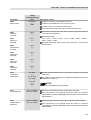
1
Motors | Automation | Energy | Transmission & Distribution | Coatings
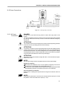
Frequency Inverter
Convertidor de Frecuencia
Inversor de Frequência
Frequenzumrichter
Variateur de Vitesse
Преодразователь частоты
Frequentie regelaar
Frekvensomvandlare
CFW-09
User's Manual
Manual del Usuario
Manual do Usuário
Bedienungsanleitung
Manuel d'utilisation
Руководство пользователя
Gebruikers handleiding
Användarinstruktioner
FREQUENCY
INVERTER
MANUAL
Series: CFW-09
Software: version 4.4X
Language: English
Document: 0899.5306 / 13
01/2011
ATTENTION!
It is very important to check if the
inverter software version is the same
as indicated above.
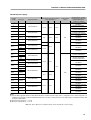
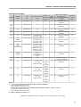
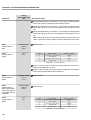
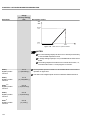
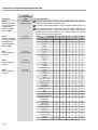
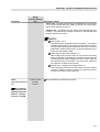
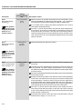
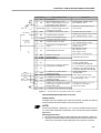
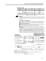
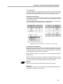
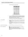
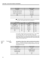
Summary of Revisions
The table below describes all revisions made to this manual.
Revision
1
2
2
2
3
4
4
5
5
5
6
7
8
8
8
8
8
8
9
9
9
10
11
12
Description
First Edition.
Inclusion of the functions Fieldbus and Serial Communication.
Inclusion of the Spare Part List.
Dimension Changing.
Inclusion of the PID Regulator.
Inclusion of the German Language - Ride-through and Flying Start functions.
Inclusion of DBW-01; KIT KME; DC Link Inductor.
Inclusion of Item 3.3 - CE Installation.
Inclusion of new functions such as Ride-Through for Vector Control, Motor Phase Loss.
New I/O Expansion Boards EBB.04 and EBB.05.
General Revision.
Inclusion of the models from 2.9 to 32 A / 500-600 V.
Inclusion of new functions:
Control Type of the Speed Regulator, Speed Regulator Differential Gain, Stop Mode Selection,
Access to the parameters with different content than default, Hysteresis for Nx/Ny, kWh
Counter, Load User 1 and 2 the factory Hours Hx, via DIx, Parameter Setting Disable via DIx,
Help Message for E24, “P406 = 2 in Vector Control”, Automatic SensorLess Set of P525, Last
10 errors indication, Motor Torque indication via AOx.
New optional boards: EBC and PLC1.
New model CFW-09 SHARK NEMA 4X/IP56.
New models for voltages, currents and powers: Models 500-600 V.
Inclusion of the items 8.14 Modbus-RTU, 8.17 CFW-09 Supplied by the DC Link - Line HD,
8.18 CFW-09 RB Regenerative Converter.
Updating of the Spare Part List.
Inclusion of new functions:
Overcurrent Protection, Default factory reset 50 Hz, Timer Relay, Ramp Holding.
New lines of the current and power supply.
PID Regulator to “Academic” Changing.
General revision and update of the software version (2.6X to 3.1X):
Change on the maximum value of P156 and P401 for some models; Change on the maximum
value of P331; Change on the factory default value of P404.
New functions;
Incorporation of the Mechanical Brake Logic for cranes, Load Detection Logic and addition of
option “Indication of Torque Current Polarity” at the DOx and RLx outputs; VVW Control; DC
Braking for VVW and Sensorless; Flying Start function for the Sensorless Control; support for
EtherNet/IP communication board; read/write function for the PLC board parameters through
Modbus; Indication of the Analog Outputs values in read only parameters P027 to P030;
Simultaneous indication of the speed and current in parameter P070; P313 = 4 (Changes to
LOCAL mode keeping the commands);Regulation of the maximum torque current through
options AI1+AI2 and AI2+AI3; function F > Fx; function ready 2.
Updating of the software version to V4.0X.
Section
Refer to item 8.12 and 8.13
Refer to item 7.5
Refer to item 3.1.2 and 9.4
Refer to item 6
Refer to item 6
Refer to item 8
Refer to item 3
Refer to item 6
Refer to item 8
Refer to items 2.4; 3.1;
3.2.1; 3.3; 4.2; 6.2; 6.3; 7.1;
7.2; 7.4; 7.5; 8.7.1; 8.10.1;
9.1 and 9.1.3
Refer to item 6
Refer to item 8
Refer to item 8
Refer to items 1 to 9
Refer to item 8
7
-
Refer to items I, 6, 7 and 8
-
Updating of the parameters P309 and P313.
Addition of new parameters: P335, P336, P337, P338, P340, P341, P342, P343, P344 and P346.
New options for fault Reset.
General revision.
13
Update of software version to V4.4X;
New incompatibilities for E24;
Fieldbus operation with mechanical brake logic;
Special function for mechanical brake logic in parameter P203.
-
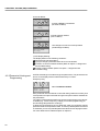
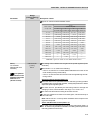
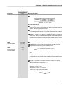
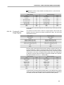
Summary
Quick Parameter Reference, Fault and Status Messages
I. Parameters ....................................................................................... 09
II.Fault Messages .................................................................................... 33
III. Other Messages ................................................................................. 34
CHAPTER
1
Safety Notices
1.1 Safety Notices in the Manual ............................................................. 35
1.2 Safety Notices on the Product ........................................................... 35
1.3 Preliminary Recommendations .......................................................... 35
CHAPTER
2
General Information
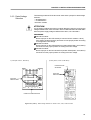
2.1 About this Manual ..............................................................................
2.2 Software Version ................................................................................
2.3 About the CFW-09 .............................................................................
2.4 CFW-09 Identification Label and Code Number ..................................
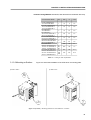
2.5 Receiving and Storage .......................................................................
37
37
37
39
41
CHAPTER
3
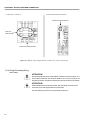
Installation and Connection
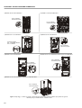
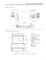
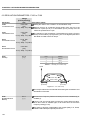
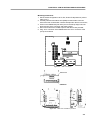
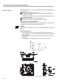
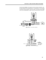
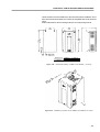
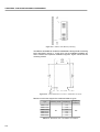
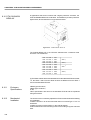
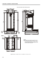
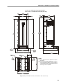
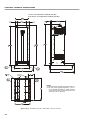
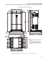
3.1 Mechanical Installation ......................................................................
3.1.1 Environment Conditions ...............................................................
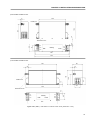
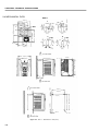
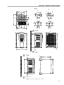
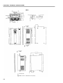
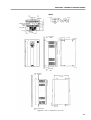
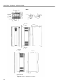
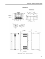
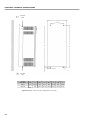
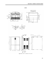
3.1.2 Dimensional of CFW-09 ...............................................................
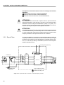
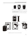
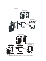
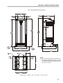
3.1.3 Mounting Specifications ...............................................................
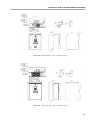
3.1.3.1 Mounting Inside a Panel .....................................................
3.1.3.2 Mounting on Surface ..........................................................
3.1.3.3 Mounting with the Heatsink Through a Surface ..................
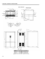
3.1.4 Keypad (HMI) and Cover Removal ................................................
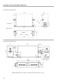
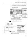
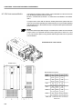
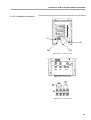
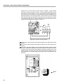
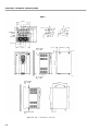
3.2 Electrical Installation ..........................................................................
3.2.1 Power/Grounding Terminals .........................................................
3.2.2 Location of the Power/Grounding/Control Connections ................
3.2.3 Rated Voltage Selection ..............................................................
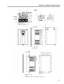
3.2.4 Power/Grounding Wiring and Fuses ............................................
3.2.5 Power Connections .....................................................................
3.2.5.1 AC Input Connection ...........................................................
3.2.5.2 Output Connections ............................................................
3.2.5.3 Grounding Connections .......................................................
3.2.5.4 IT Networks .........................................................................
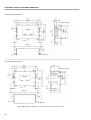
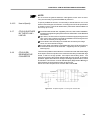
3.2.6 Control Wiring ..............................................................................
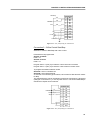
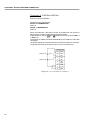
3.2.7 Typical Terminal Connections ......................................................
3.3 European EMC Directive - Requirements for Conforming Installations
3.3.1 Installation ...................................................................................
3.3.2 Epcos Filters ...............................................................................
3.3.3 Schaffner Filters ...........................................................................
3.3.4 EMC Filter Characteristics ...........................................................
42
42
42
43
44
45
46
48
49
49
51
53
54
57
57
58
58
59
61
64
67
67
68
71
74
Summary
CHAPTER
4
Keypad (HMI) Operation
4.1 Description of the Keypad ..................................................................
4.2 Use of the Keypad (HMI) ....................................................................
4.2.1 Keypad Operation ........................................................................
4.2.2 "Read-Only" Variables and Status ...............................................
4.2.3 Parameter Viewing and Programming .........................................
CHAPTER
86
88
88
89
90
5
Start-up
5.1 Pre-Power Checks ............................................................................ 93
5.2 Initial Power-up ................................................................................. 93
5.3 Start-up ............................................................................................. 98
5.3.1 Type of Control: V/F 60 Hz - Operation via Keypad (HMI) ............ 99
5.3.2 Type of Control: Sensorless or Vector with Encoder
(Operation Via Keypad (HMI)) ..................................................... 102
5.3.3 Type of Control: VVW - Keypad Operation ................................. 109
CHAPTER
6
Detailed Parameter Description
6.1 Access and Read Only Parameters - P000 to P099 ......................... 118
6.2 Regulation Parameters - P100 to P199 ............................................. 124
6.3 Configuration Parameters - P200 to P399 ......................................... 147
6.3.1 Parameters for Crane Applications and for Torque Master/Slave
Function - P351 to P368 ........................................................... 208
6.4 Motor Parameters - P400 to P499 .................................................... 214
6.5 Special Functions Parameters - P500 to P699 ................................. 220
6.5.1 PID Regulator ............................................................................. 220
6.5.2 Description ................................................................................. 220
CHAPTER
7
Diagnostics and Troubleshooting
7.1 Faults and Possible Causes ............................................................. 228
7.2 Troubleshooting ................................................................................ 233
7.3 Contacting WEG ............................................................................... 235
7.4 Preventive Maintenance .................................................................... 235
7.4.1 Cleaning Instructions .................................................................. 236
7.5 Spare Part List .................................................................................. 237
CHAPTER
8
CFW-09 Options and Accessories
8.1 I/O Expansion Boards ....................................................................... 248
8.1.1 EBA (I/O Expansion Board A) ..................................................... 248
Summary
8.1.2 EBB (I/O Expansion Board B) .................................................... 251
8.1.3 EBE ............................................................................................ 254
8.2 Incremental Encoder ......................................................................... 254
8.2.1 EBA/EBB Boards ....................................................................... 254
8.2.2 EBC1 Board ................................................................................ 256
8.3 Keypad with LEDs Only .................................................................... 258
8.4 Remote Keypad and Cables ............................................................. 258
8.5 Blank Covers ..................................................................................... 262
8.6 RS-232 PC Communication Kit ......................................................... 262
8.7 Line Reactor/DC Bus Choke ............................................................. 263
8.7.1 Application Criteria ...................................................................... 264
8.7.2 DC Link Inductor Built in ............................................................. 266
8.8 Load Reactor .................................................................................... 267
8.9 RFI Filter ........................................................................................... 267
8.10 Dynamic Braking ............................................................................ 268
8.10.1 DB Resistor Sizing .................................................................. 268
8.10.2 Installation ............................................................................... 270
8.10.3 Dynamic Braking Module-DBW-01 and DBW-02 ..................... 271
8.10.3.1 DBW-01 and DBW-02 Identification Label ................... 272
8.10.3.2 Mechanical Installation ................................................ 272
8.10.3.3 Installation/Connection ................................................ 275
8.11 Through Surface Mounting Kit ......................................................... 277
8.12 Fieldbus ........................................................................................... 277
8.12.1 Installation of the Fieldbus Kit ................................................. 278
8.12.2 Profibus DP ............................................................................. 281
8.12.3 Profibus DP-V1 ....................................................................... 283
8.12.4 DeviceNet ................................................................................ 284
8.12.5 DeviceNet Drive Profile ............................................................ 286
8.12.6 EtherNet/IP ............................................................................. 287
8.12.7 Use to the Fieldbus/Related Parameters of the CFW-09 ......... 294
8.12.7.1 Variables Read from the Inverter .................................. 294
8.12.7.2 Variables Written in the Inverter ................................... 296
8.12.7.3 Fault Indications .......................................................... 298
8.12.7.4 Addressing of the CFW-09 Variables in the
Fieldbus Devices ......................................................... 299
8.13 Serial Communication ..................................................................... 300
8.13.1 Introduction ............................................................................. 300
8.13.2 Interfaces Description .............................................................. 301
8.13.2.1 RS-485 ......................................................................... 301
8.13.2.2 RS-232 ......................................................................... 302
8.13.3 Protocol Definitions ................................................................. 302
8.13.3.1 Used Terms .................................................................. 302
8.13.3.2 Parameters/Variables Resolution .................................. 303
8.13.3.3 Characters Format ........................................................ 303
8.13.3.4 Protocol ........................................................................ 303
8.13.3.5 Execution and Telegram Test ....................................... 305
8.13.3.6 Telegram Sequence ...................................................... 306
8.13.3.7 Variable Code ............................................................... 306
8.13.4 Telegram Examples ................................................................. 306
8.13.5 Variables and Errors of the Serial Communication .................. 307
8.13.5.1 Basic Variables ............................................................. 307
8.13.5.2 Examples of Telegrams with Basic Variables ............... 310
8.13.5.3 Parameters Related to the Serial Communication ........ 311
8.13.5.4 Errors Related to the Serial Communication ................. 312
Summary
8.13.6 Times for Read/Write of Telegrams .......................................... 312
8.13.7 Physical Connection of the RS-232 and RS-485 Interface ........ 313
8.14 Modbus-RTU .................................................................................... 314
8.14.1 Introduction in the Modbus-RTU Protocol ................................ 314
8.14.1.1 Transmission Modes .................................................... 314
8.14.1.2 Message Structure in RTU Mode .................................. 314
8.14.2 Operation of the CFW-09 in the Modbus-RTU Network ........... 316
8.14.2.1 Interface RS-232 and RS-485 Description ..................... 316
8.14.2.2 Inverter Configuration in the Modbus-RTU Network ...... 317
8.14.2.3 Access to the Inverter Data ........................................... 317
8.14.3 Detailed Function Description ................................................... 320
8.14.3.1 Function 01 - Read Coils .............................................. 321
8.14.3.2 Function 03 - Read Holding Register ............................ 321
8.14.3.3 Function 05 - Write Single Coil ..................................... 322
8.14.3.4 Function 06 - Write Single Register .............................. 323
8.14.3.5 Function 15 - Write Multiple Coils ................................. 324
8.14.3.6 Function 16 - Write Multiple Registers ......................... 325
8.14.3.7 Function 43 - Read Device Identification ....................... 326
8.14.4 Communication Errors ............................................................. 327
8.14.4.1 Error Messages ............................................................ 327
8.15 KIT KME (for Extractable Mounting) ................................................ 329
8.16 CFW-09 SHARK NEMA 4X ............................................................. 330
8.16.1 Enclosure Specifications ......................................................... 330
8.16.2 Mechanical Installation ............................................................ 330
8.16.3 Electrical Installation ............................................................... 332
8.16.4 Closing the Inverter .................................................................. 332
8.16.5 How to Specify ........................................................................ 333
8.17 CFW-09 Supplied by the DC Link - Line HD ................................... 333
8.18 CFW-09 RB Regenerative Converter ............................................... 333
8.19 PLC Board ...................................................................................... 335
CHAPTER 9
Technical Specification
9.1 Power Data ...................................................................................... 336
9.1.1 Power Supply Specifications ...................................................... 336
9.1.2 220-230 V Power Supply ............................................................ 337
9.1.3 380-480 V Power Supply ............................................................ 337
9.1.4 500-600 V Power Supply ............................................................ 338
9.1.5 660-690 V Power Supply ............................................................ 340
9.2 Electronics/General Data .................................................................. 343
9.2.1 Applicable Standards .................................................................. 344
9.3 Optional Devices ............................................................................... 345
9.3.1 I/O Expansion Board EBA .......................................................... 345
9.3.2 I/O Expansion Board EBB .......................................................... 345
9.4 Mechanical Data ............................................................................... 346
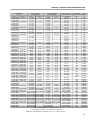
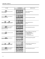
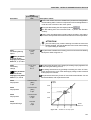
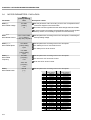
CFW-09 - QUICK PARAMETER REFERENCE
QUICK PARAMETER REFERENCE, FAULT AND STATUS MESSAGES
Software: V4.4X
Application:
CFW-09 Model:
Serial Number:
Responsible:
Date:
/
/
.
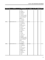
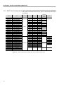
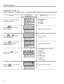
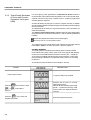
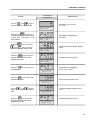
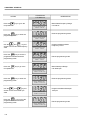
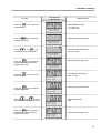
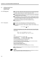
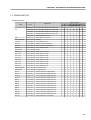
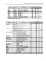
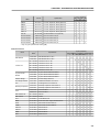
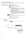
I. Parameters
Parameters
Function
Factory
Setting
Adjustable Range
0 to 999
P001 to P099
0
Unit
-
User's
Setting
Page
P000
Parameter Access
READ ONLY PARAMETERS
118
P001
Speed Reference
0.0 to P134
rpm
118
P002
Motor Speed
0.0 to P134
rpm
118
P003
Motor Current
0.0 to 2600
A (rms)
118
P004
DC Link Voltage
0.0 to 1235
V
119
P005
Motor Frequency
0.0 to 1020
Hz
119
P006
Inverter Status
rdy
-
119
V
119
run
Sub
Exy
P007
Motor Voltage
0 to 800
P009
Motor Torque
0.0 to 150.0
%
119
P010
Output Power
0.0 to 3276
kW
119
P012
Digital Inputs DI1 ... DI8 Status
0 = Inactive (Open)
-
119
-
120
1 = Active (Closed)
P013
Digital and Relay Outputs DO1, DO2,
0 = Inactive (Dropped-out)
RL1, RL2, and RL3 Status
1 = Active (Picked-up)
P014
Last Fault
0 to 71
-
121
P015
Second Previous Fault
0 to 71
-
121
P016
Third Previous Fault
0 to 71
-
121
P017
Fourth Previous Fault
0 to 71
-
121
P018
Analog Input AI1’ Value
-100 to +100
%
121
P019
Analog Input AI2’ Value
-100 to +100
%
121
P020
Analog Input AI3’ Value
-100 to +100
%
121
P021
Analog Input AI4’ Value
-100 to +100
%
121
P022
WEG Use
-
-
121
P023
Software Version
V4.4X
-
121
P024
A/D Conversion Value of AI4
-32768 to +32767
-
121
P025
A/D Conversion Value of Iv
0 to 1023
-
121
P026
A/D Conversion Value of Iw
0 to 1023
-
121
P027
AO1 Value
0.0 to 100
%
122
P028
AO2 Value
0.0 to 100
%
122
P029
AO3 Value
-100 to +100
%
122
P030
AO4 Value
-100 to +100
%
122
P040
PID Process Variable
0 to 100
%
122
P042
Powered Time
0 to 65535
h
122
P043
Enabled Time
0 to 6553.5
h
122
P044
kWh Counter
0 to 65535
kWh
123
9
CFW-09 - QUICK PARAMETER REFERENCE
Parameters
Function
Factory
Setting
Adjustable Range
Unit
User's
Setting
Page
P060
Fifth Error
0 to 71
-
123
P061
Sixth Error
0 to 71
-
123
P062
Seventh Error
0 to 71
-
123
P063
Eighth Error
0 to 71
-
123
P064
Ninth Error
0 to 71
-
123
P065
Tenth Error
0 to 71
-
123
P070
Motor Current and Motor Speed
0 to 2600
A (rms)
123
0 to P134
rpm
P071
Command Word
0 a 65535
-
123
P072
Fieldbus Speed Reference
0 a 65535
-
123
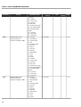
REGULATION PARAMETERS
P100 to P199
Ramps
P100
Acceleration Time
0.0 to 999
20.0
s
124
P101
Deceleration Time
0.0 to 999
20.0
s
124
P102
Acceleration Time 2
0.0 to 999
20.0
s
124
P103
Deceleration Time 2
0.0 to 999
20.0
s
124
P104
S Ramp
0 = Inactive (Linear)
0 = Inactive
-
124
1 = Active
-
124
125
1 = 50 %
2 = 100 %
Speed References
P120
Speed Reference Backup
0 = Inactive
1 = Active
P121
Keypad Speed Reference
P133 to P134
90
rpm
P122 (2) (11)
JOG or JOG+ Speed Reference
00 to P134
150 (125)
rpm
125
P123 (2) (11)
JOG- Speed Reference
00 to P134
150 (125)
rpm
125
P124 (2) (11)
Multispeed Reference 1
P133 to P134
90 (75)
rpm
126
(2) (11)
Multispeed Reference 2
P133 to P134
300 (250)
rpm
126
P126 (2) (11)
Multispeed Reference 3
P133 to P134
600 (500)
rpm
126
P127 (2) (11)
Multispeed Reference 4
P133 to P134
900 (750)
rpm
126
P128 (2) (11)
Multispeed Reference 5
P133 to P134
1200 (1000)
rpm
126
(2) (11)
Multispeed Reference 6
P133 to P134
1500 (1250)
rpm
126
P130 (2) (11)
Multispeed Reference 7
P133 to P134
1800 (1500)
rpm
126
P131 (2) (11)
Multispeed Reference 8
P133 to P134
1650 (1375)
rpm
126
(0 to 99) x P134
10
%
127
P125
P129
Speed Limits
P132
(1)
Maximum Overspeed Level
100 = Disabled
P133 (2) (11)
Minimum Speed Reference
0 to (P134-1)
90 (75)
rpm
127
P134 (2) (11)
Maximum Speed Reference
(P133+1) to (3.4 x P402)
1800 (1500)
rpm
127
rpm
128
-
128
I/F Control
P135 (2)
Speed transition to I/F Control
0 to 90
18
P136 (*)
Current Reference (I*)
0 = Imr
1 = 1.11 x Imr
for I/F Control
1 = 1.11 x Imr
2 = 1.22 x Imr
3 = 1.33 x Imr
4 = 1.44 x Imr
5 = 1.55 x Imr
6 = 1.66 x Imr
7 = 1.77 x Imr
8 = 1.88 x Imr
9 = 2.00 x Imr
(*) P136 has different functions for V/F and Vector Control.
10
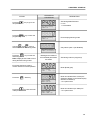
CFW-09 - QUICK PARAMETER REFERENCE
Parameters
Function
Factory
Setting
Adjustable Range
Unit
User's
Setting
Page
V/F Control
P136 (*)
Manual Boost Torque
P137
Autommatic Torque Boost
0.00 to 1.00
0.00
-
130
P138
Slip Compensation
-10.0 to +10.0
0.0
%
130
P139
Output Current Filter
0.00 to 16.00
1.00
s
131
P140
Dwell Time at Start
0.0 to 10.0
0.0
s
131
P141
Dwell Speed at Start
0 to 300
90
rpm
131
0 to 9
1
-
129
Adjustable V/F
P142 (1)
Maximum Output Voltage
0.0 to 100.0
100.0
%
132
P143 (1)
Intermediate Output Voltage
0.0 to 100.0
50.0
%
132
P144
(1)
Output Voltage at 3 Hz
0.0 to 100.0
8.0
%
132
P145 (1)
Field Weakening Speed
P133 (> 90) to P134
1800
rpm
132
P146 (1)
Intermediate Speed
90 to P145
900
rpm
132
0 = With Losses
1 = Without Losses
-
133
V
133 and
DC Link Voltage Regulation
P150 (1)
DC Link Voltage Regulation Mode
1 = Without Losses
2 = Enable/Disable
via DI3...DI8
P151
(6) (*)
DC Link Voltage Regulation Level
339 to 400 (P296 = 0)
400
(V/F Control / Vector Control
585 to 800 (P296 = 1)
800
with optimal braking)
616 to 800 (P296 = 2)
800
678 to 800 (P296 = 3)
800
739 to 800 (P296 = 4)
800
809 to 1000 (P296 = 5)
1000
885 to 1000 (P296 = 6)
1000
924 to 1000 (P296 = 7)
1000
136
1063 to 1200 (P296 = 8)
1200
P152
Proportional Gain
0.00 to 9.99
0.00
-
137
P153 (6)
Dynamic Braking Level
339 to 400 (P296 = 0)
375
V
137
585 to 800 (P296 = 1)
618
616 to 800 (P296 = 2)
675
678 to 800 (P296 = 3)
748
P154
P155
739 to 800 (P296 = 4)
780
809 to 1000 (P296 = 5)
893
885 to 1000 (P296 = 6)
972
924 to 1000 (P296 = 7)
972
1063 to 1200 (P296 = 8)
1174
Dynamic Braking Resistor
0.0 to 500
0.0
138
DB Resistor Power Rating
0.00 to 650
2.60
kW
138
Overload Currents
P156 (2) (7) (12)
Overload Current 100 % Speed
P157 to 1.3 x P295
1.1 x P401
A
139
P157 (2) (7)
Overload Current 50 % Speed
P156 to P158
0.9 x P401
A
139
Overload Current 5 % Speed
(0.2 x P295) to P157
0.55 x P401
A
139
Optimization of the
0 = Normal
0 = Normal
-
140
Speed Regulator
1 = Saturated
P158 (2) (7)
Speed Regulator
P160 (1)
P161 (3)
Proportional Gain
0.0 to 63.9
7.4
-
142
P162 (3)
Integral Gain
0.000 to 9.999
0.023
-
142
P163
Local Speed Reference Offset
-999 to +999
0
-
143
P164
Remote Speed Reference Offset
-999 to +999
0
-
143
(*) P151 has different function for V/F or Vector Control.
11
CFW-09 - QUICK PARAMETER REFERENCE
Parameters
Function
Factory
Setting
Adjustable Range
Unit
User's
Setting
Page
P165
Speed Filter
0.012 to 1.000
0.012
s
143
P166
Speed Regulator Differential Gain
0.00 to 7.99
0.00 (without
-
143
differential action)
Current Regulator
P167 (4)
Proportional Gain
0.00 to 1.99
0.50
-
143
P168 (4)
Integral Gain
0.000 to 1.999
0.010
-
143
P169
Maximum Output Current (V/F Control) (0.2 x P295) to (1.8 x P295)
1.5 x P295
A
144
Maximum Forward Torque Current
0 to 180
125
%
144
0 to 180
125
%
144
0 to 180
125
%
145
0 to 180
125
%
145
0 = Ramp
0 = Ramp
-
145
146
(*) (7)
P169 (*) (7)
(Vector Control)
P170
Maximum Reverse Torque Current
(Vector Control)
P171
Maximum Forward Torque Current at
Maximum Speed (P134)
P172
Maximum Reverse Torque Current at
Maximum Speed (P134)
P173
Curve Type of the Max. Torque
1 = Step
Flux Regulator
P175
Proportional Gain
0.0 to 31.9
2.0
-
P176 (5)
Integral Gain
0.000 to 9.999
0.020
-
146
P177
Minimum Flux
0 to 120
0
%
146
P178
Nominal Flux
0 to 120
100
%
146
P179
Maximum Flux
0 to 120
120
%
146
P180
Field Weakenig Start Point
0 to 120
95
%
146
P181 (1)
Magnetization Mode
0 = General Enable
0 = General Enable
-
146
1 = On
-
147
0, 1, 2, 3 (11)
-
147
0 (1)
-
147
0 = None
-
147
0 = Not Used
-
148
(5)
1 = Start/Stop
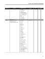
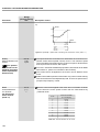
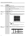
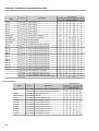
CONFIGURATION PARAMETERS
P200 to P399
Generic Parameters
P200
Password
0 = Off
1 = On
P201 (11)
Language Selection
0 = Português
1 = English
2 = Español
3 = Deutsch
P202
(1) (2) (11)
Type of Control
0 = V/F 60 Hz
1 = V/F 50 Hz
2 = V/F Adjustable
3 = Sensorless Vector
4 = Vector with Encoder
5 = VVW (Voltage Vector WEG)
P203 (1)
Special Function Selection
0 = None
1 = PID Regulator
2 = Mechanical Brake Logic
P204 (1) (10)
Load/Save Parameters
0 = Not Used
1 = Not Used
2 = Not Used
3 = Reset P043
4 = Reset P044
5 = Loads Factory Default-60 Hz
6 = Loads Factory Default-50 Hz
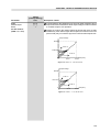
(*) P169 has different function for V/F or Vector Control.
12
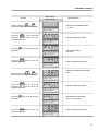
CFW-09 - QUICK PARAMETER REFERENCE
Parameters
Function
Factory
Setting
Adjustable Range
Unit
User's
Setting
Page
7 = Loads User Default 1
8 = Loads User Default 2
9 = Not Used
10 = Save User Default 1
11 = Save User Default 2
P205
Display Default Selection
0 = P005 (Motor Frequency) 2 = P002
-
149
1 = P003 (Motor Current)
2 = P002 (Motor Speed)
3 = P007 (Motor Voltage)
4 = P006 (Inverter Status)
5 = P009 (Motor Torque)
6 = P070 (Motor Speed and
Motor Current)
7 = P040 (PID Process
Variable)
P206
Auto-Reset Time
0 to 255
0
s
150
P207
Reference Engineering Unit 1
32 to 127 (ASCII)
114 = r
-
150
A, B, ... , Y, Z
0, 1, ... , 9
#, $, %, (, ), *, +, ...
P208 (2) (11)
Reference Scale Factor
1 to 18000
1800 (1500)
-
150
P209 (1)
Motor Phase Loss Detection
0 = Off
0 = Off
-
151
P210
Decimal Point of the Speed Indication 0 to 3
0
-
151
P211(1)
Zero Speed Disable
0 = Off
-
151
0 = N* or N>P291
-
152
1 = On
0 = Off
1 = On
P212
Condition to Leave Zero
0 = N* or N>P291
Speed Disable
1 = N*>P291
P213
Time Delay for Zero Speed Disable
0 to 999
0
s
152
P214 (1) (9)
Line Phase Loss Detection
0 = Off
1 = On
-
152
P215 (1)
Keypad Copy Function
0 = Off
0 = Off
-
152
112 = p
-
154
109 = m
-
154
0 to 150
127
-
154
0 = Always Local
2 = Keypad
-
154
1 = Always Remote
(Default Local)
1 = On
P216
Reference Engineering Unit 2
1 = Inverter
Keypad
2 = Keypad
Inverter
32 to 127 (ASCII)
A, B, ... , Y, Z
0, 1, ... , 9
#, $, %, (, ), *, +, ...
P217
Reference Engineering Unit 3
32 to 127 (ACSII)
A, B, ... , Y, Z
0, 1, ... , 9
#, $, %, (, ), *, +, ...
P218
LCD Display Contrast
Adjustment
Local/Remote Definition
P220 (1) (8)
Local/Remote Selection Source
2 = Keypad (Default Local)
3 = Keypad (Default Remote)
13
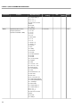
CFW-09 - QUICK PARAMETER REFERENCE
Parameters
Function
Adjustable Range
Factory
Setting
Unit
User's
Setting
Page
4 = DI2 to DI8
5 = Serial (L)
6 = Serial (R)
7 = Fieldbus (L)
8 = Fieldbus (R)
9 = PLC (L)
10 = PLC (R)
P221(1)
Local Speed Reference Selection
0 = keypad
0 = Keypad
-
155
1 = AI1
-
155
0 = Always Forward
2 = Keypad
-
156
1 = Always Reverse
(Default FWD)
0 = [I] and [O] Keys
-
156
1 = Keypad
-
156
1 = AI1
2 = AI2
3 = AI3
4 = AI4
5 = Add AI > 0
6 = Add AI
7 = E.P.
8 = Multispeed
9 = Serial
10 = Fieldbus
11 = PLC
P222(1) (8)
Remote Speed Reference
0 = keypad
Selection
1 = AI1
2 = AI2
3 = AI3
4 = AI4
5 = Add AI > 0
6 = Add AI
7 = E.P.
8 = Multispeed
9 = Serial
10 = Fieldbus
11 = PLC
P223 (1) (8)
Local FWD/REV Selection
2 = Keypad (Default FWD)
3 = Keypad (Default REV)
4 = DI2
5 = Serial (Default FWD)
6 = Serial (Default REV)
7 = Fieldbus (Default FWD)
8 = Fieldbus (Default REV)
9 = Polarity AI4
10 = PLC (FWD)
11 = PLC (REV)
P224 (1) (8)
Local Start/Stop Selection
0 = [I] and [O] Keys
1 = DIx
2 = Serial
3 = Fieldbus
4 = PLC
P225 (1) (8)
Local JOG Selection
0 = Disable
1 = Keypad
14
CFW-09 - QUICK PARAMETER REFERENCE
Parameters
Function
Factory
Setting
Adjustable Range
Unit
User's
Setting
Page
2 = DI3 to DI8
3 = Serial
4 = Fieldbus
5 = PLC
P226 (1) (8)
Remote FWD/REV Selection
0 = Always Forward
4 = DI2
-
157
1 = DIx
-
157
2 = DI3 to DI8
-
157
0 = Ramp to Stop
-
163
0 = Off
-
163
1 = Always Reverse
2 = Keypad (Default FWD)
3 = Keypad (Default REV)
4 = DI2
5 = Serial (Default FWD)
6 = Serial (Default REV)
7 = Fieldbus (Default FWD)
8 = Fieldbus (Default REV)
9 = Polarity AI4
10 = PLC (FWD)
11 = PLC (REV)
P227 (1) (8)
Remote Start/Stop Selection
0 = [I] and [O] Keys
1 = DIx
2 = Serial
3 = Fieldbus
4 = PLC
P228
(1) (8)
Remote JOG Selection
0 = Disable
1 = Keypad
2 = DI3 to DI8
3 = Serial
4 = Fieldbus
5 = PLC
Stop Model Definition
P232 (1)
Stop Mode Selection
0 = Ramp to Stop
1 = Coast to Stop
2 = Fast Stop
Analog Inputs
P233
Analog Inputs Dead Zone
0 = Off
P234
Analog Input AI1 Gain
0.000 to 9.999
P235 (1)
Analog Input AI1 Signal
0 = (0 to 10) V / (0 to 20) mA 0 = (0 to 10) V /
1 = On
1 = (4 to 20) mA
1.000
-
164
-
165
(0 to 20) mA
2 = (10 to 0) V / (20 to 0) mA
3 = (20 to 4) mA
P236
Analog Input AI1 Offset
-100.0 to +100.0
0.0
%
165
P237 (1) (8)
Analog Input AI2 Function
0 = P221/P222
0 = P221/P222
-
165
1.000
-
166
1 = N* without ramp
2 = Maximum Torque Current
3 = PID Process Variable
4 = Maximum Torque Current
(AI2 + AI1)
P238
Analog Input AI2 Gain
0.000 to 9.999
15
CFW-09 - QUICK PARAMETER REFERENCE
Parameters
P239
(1)
Function
Analog Input AI2 Signal
Factory
Setting
Adjustable Range
0 = (0 to 10) V / (0 to 20) mA 0 = (0 to 10) V /
1 = (4 to 20) mA
Unit
-
User's
Setting
Page
166
(0 to 20) mA
2 = (10 to 0) V / (20 to 0) mA
3 = (20 to 4) mA
P240
Analog Input AI2 Offset
-100.0 to +100.0
0.0
%
167
P241 (1) (8)
Analog Input AI3 Function
0 = P221/P222
0 = P221/P222
-
167
(Requires Optional I/O Expansion
1 = Without ramp
Board EBB)
2 = Maximum Torque Current
3 = PID Process Variable
4 = Maximum Torque Current
(AI3 + AI2)
P242
Analog Input AI3 Gain
0.000 to 9.999
P243 (1)
Analog Input AI3 Signal
0 = (0 to 10) V / (0 to 20) mA 0 = (0 to 10) V /
1 = (4 to 20) mA
1.000
-
168
-
168
(0 to 20) mA
2 = (10 to 0) V / (20 to 0) mA
3 = (20 to 4) mA
P244
Analog Input AI3 Offset
-100.0 to +100.0
0.0
%
168
P245
Analog Input AI4 Gain
0.000 to 9.999
1.000
-
168
P246 (1)
Analog Input AI4 Signal
0 = (0 to 10) V / (0 to 20) mA 0 = (0 to 10) V /
-
168
(Requires Optional I/O Expansion
1 = (4 to 20) mA
Board EBA)
2 = (10 to 0) V / (20 to 0) mA
(0 to 20) mA
3 = (20 to 4) mA
4 = (-10 to +10) V
P247
Analog Input AI4 Offset
-100.0 to +100.0
0.0
%
169
P248
Input Filter AI2
0.0 to 16.0
0.0
s
169
Analog Output AO1 Function
0 = Speed Reference
2 = Real Speed
-
169
(CC9 or EBB board)
1 = Total Reference
Analog Outputs
P251
2 = Real Speed
3 = Torque Current
Reference (Vector)
4 = Torque Current (Vector)
5 = Output Current
6 = PID Process Variable
7 = Active Current (V/F)
8 = Power (kW)
9 = PID Setpoint
10 = Positive Torque Current
11 = Motor Torque
12 = PLC
13 = Dead Zone for
Speed Indication
14 = Motor Voltage
P252
Analog Output AO1 Gain
0.000 to 9.999
1.000
-
169
P253
Analog Output AO2 Function
0 = Speed Reference
5 = Output Current
-
169
(CC9 or EBB board)
1 = Total Reference
2 = Real Speed
3 = Torque Current
Reference (Vector)
16
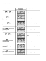
CFW-09 - QUICK PARAMETER REFERENCE
Parameters
Function
Factory
Setting
Adjustable Range
Unit
User's
Setting
Page
4 = Torque Current (Vector)
5 = Output Current
6 = PID Process Variable
7 = Active Current (V/F)
8 = Power (kW)
9 = PID Setpoint
10 = Positive Torque Current
11 = Motor Torque
12 = PLC
13 = Dead Zone for
Speed Indication
14 = Motor Voltage
P254
Analog Output AO2 Gain
0.000 to 9.999
1.000
-
169
P255
Analog Output AO3 Function
0 = Speed Reference
2 = Real Speed
-
169
(Requires Optional I/O Expansion
1 = Total Reference
Board EBA)
2 = Real Speed
3 = Torque Current
Reference (Vector)
4 = Torque Current (Vector)
5 = Output Current
6 = PID Process Variable
7 = Active Current (V/F)
8 = Power (kW)
9 = PID Setpoint
10 = Positive Torque Current
11 = Motor Torque
12 = PLC
13 = Not Used
14 = Motor Voltage
15 to 63 = Exclusive WEG use
P256
Analog Output AO3 Gain
0.000 to 9.999
1.000
-
170
P257
Analog Output AO4 Function
0 = Speed Reference
5 = Output Current
-
170
(Requires optional I/O Expansion
1 = Total Reference
Board EBA)
2 = Real Speed
3 = Torque Current
Reference (Vector)
4 = Torque Current (Vector)
5 = Output Current
6 = PID Process Variable
7 = Active Current (V/F)
8 = Power (kW)
9 = PID Setpoint
10 = Positive Torque Current
11 = Motor Torque
12 = PLC
13 = Not Used
14 = Motor Voltage
15 to 63 = Exclusive WEG use
P258
Analog Output AO4 Gain
0.000 to 9.999
1.000
-
170
P259
Dead Zone for Speed Indication
0 to P134
1000
rpm
171
17
CFW-09 - QUICK PARAMETER REFERENCE
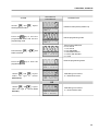
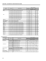
Parameters
Function
Adjustable Range
Factory
Setting
Unit
User's
Setting
Page
Digital Inputs
P263 (1) (8)
Digital Input DI1 Function
0 = Not Used
1 = Start/Stop
-
172
0 = FWD/REV
-
172
0 = Not Used
-
172
0 = Not Used
-
172
1 = Start/Stop
2 = General Enable
3 = Fast Stop
P264 (1) (8)
Digital Input DI2 Function
0 = FWD/REV
1 = Local/Remote
2 = Not Used
3 = Not Used
4 = Not Used
5 = Not Used
6 = Not Used
7 = Not Used
8 = Reverse Run
P265 (1) (8)
Digital Input DI3 Function
0 = Not Used
1 = Local/ Remote
2 = General Enable
3 = JOG
4 = No External Fault
5 = Increase E.P.
6 = Ramp 2
7 = Not Used
8 = Forward Run
9 = Speed/Torque
10 = JOG+
11 = JOG12 = Reset
13 = Fieldbus
14 = Start (3 wire)
15 = Man/Auto
16 = Not used
17 = Disables Flying Start
18 = DC Voltage Regulator
19 = Parameter Setting
Disable
20 = Load user
21 = Timer (RL2)
22 = Timer (RL3)
P266 (1)
Digital Input DI4 Function
0 = Not used
1 = Local/ Remote
2 = General Enable
3 = JOG
4 = No external Fault
5 = Decrease E.P.
6 = Ramp 2
7 = Multispeed (MS0)
8 = Reverse Run
9 = Speed/Torque
10 = JOG+
18
CFW-09 - QUICK PARAMETER REFERENCE
Parameters
Function
Adjustable Range
Factory
Setting
Unit
User's
Setting
Page
11 = JOG12 = Reset
13 = Fieldbus
14 = Stop (3 wire)
15 = Man/Auto
16 = Not used
17 = Disables Flying Start
18 = DC voltage regulator
19 = Parameter Setting
Disable
20 = Load User
21 = Timer (RL2)
22 = Timer (RL3)
P267
(1)
Digital Input DI5 Function
0 = Not Used
3 = JOG
-
172
6 = Ramp 2
-
173
1 = Local/ Remote
2 = General Enable
3 = JOG
4 = No External Fault
5 = Increase E.P.
6 = Ramp 2
7 = Multispeed (MS1)
8 = Fast Stop
9 = Speed/Torque
10 = JOG+
11 = JOG12 = Reset
13 = Fieldbus
14 = Start (3 wire)
15 = Man/Auto
16 = Not Used
17 = Disables Flying Start
18 = DC Voltage Regulator
19 = Parameter Setting
Disable
20 = Load User
21 = Timer (RL2)
22 = Timer (RL3)
P268
(1)
Digital Input DI6 Function
0 = Not Used
1 = Local/ Remote
2 = General Enable
3 = JOG
4 = No External Fault
5 = Decrease E.P.
6 = Ramp 2
7 = Multispeed (MS2)
8 = Fast Stop
9 = Speed/Torque
10 = JOG+
11 = JOG-
19
CFW-09 - QUICK PARAMETER REFERENCE
Parameters
Function
Adjustable Range
Factory
Setting
Unit
User's
Setting
Page
12 = Reset
13 = Fieldbus
14 = Stop (3 wire)
15 = Man/Auto
16 = Not Used
17 = Disables Flying Start
18 = DC voltage regulator
19 = Parameter setting
disable
20 = Load user
21 = Timer (RL2)
22 = Timer (RL3)
P269 (1)
Digital Input DI7 Function
0 = Not Used
(Requires optional I/O
1 = Local/ Remote
expansion board EBA or EBB)
2 = General Enable
0 = Not used
-
173
0 = Not used
-
173
3 = JOG
4 = No External Fault
5 = Not Used
6 = Ramp 2
7 = Not Used
8 = Fast Stop
9 = Speed/Torque
10 = JOG+
11 = JOG12 = Reset
13 = Fieldbus
14 = Start (3 wire)
15 = Man/Auto
16 = Not Used
17 = Disables Flying Start
18 = DC Voltage Regulator
19 = Parameter Setting
Disable
20 = Load User
21 = Timer (RL2)
22 = Timer (RL3)
P270 (1)
Digital Input DI8 Function
0 = Not used
(Requires optional I/O
1 = Local/Remote
expansion board EBA or EBB)
2 = General Enable
3 = JOG
4 = No External Fault
5 = Not Used
6 = Ramp 2
7 = Not Used
8 = Fast Stop
9 = Speed/Torque
10 = JOG+
11 = JOG12 = Reset
20
CFW-09 - QUICK PARAMETER REFERENCE
Parameters
Function
Adjustable Range
Factory
Setting
Unit
User's
Setting
Page
13 = Fieldbus
14 = Stop (3 wire)
15 = Man/Auto
16 = Motor Thermistor
17 = Disables Flying Start
18 = DC Voltage Regulator
19 = Parameter Setting
Disable
20 = Not Used
21 = Timer (RL2)
22 = Timer (RL3)
Digital Outputs
P275 (1)
Digital Ouput DO1 Function
0 = Not used
(requires optional I/O
1 = N* > Nx
expansion board EBA or EBB)
2 = N > Nx
0 = Not Used
-
180
3 = N < Ny
4 = N = N*
5 = Zero Speed
6 = Is > Ix
7 = Is < Ix
8 = Torque > Tx
9 = Torque < Tx
10 = Remote
11 = Run
12 = Ready
13 = No Fault
14 = No E00
15 = No E01+E02+E03
16 = No E04
17 = No E05
18 = (4 to 20) mA OK
19 = Fieldbus
20 = FWD
21 = Proc.Var. > VPx
22 = Proc. Var. < VPy
23 = Ride-Through
24 = Pre-charge OK
25 = Fault
26 = Enabled Hours > Hx
27 = Not Used
28 = Not Used
29 = N > Nx and Nt > Nx
30 = Brake (Actual Speed)
31 = Brake (Total Reference)
32 = Overweight
33 = Slack Cable
34 = Torque Polarity +/-
21
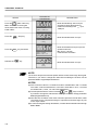
CFW-09 - QUICK PARAMETER REFERENCE
Parameters
Function
Adjustable Range
Factory
Setting
Unit
User's
Setting
Page
35 = Torque Polarity -/+
36 = F > Fx _ 1
37 = F > Fx _ 2
38 = Set Point = Process
Variable
39 = No E32
40 = Ready 2
P276 (1)
Digital Output DO2 Function
0 = Not Used
(Requires optional I/O
1 = N* > Nx
expansion board EBA or EBB)
2 = N > Nx
3 = N < Ny
4 = N = N*
5 = Zero Speed
6 = Is > Ix
7 = Is < Ix
8 = Torque > Tx
9 = Torque < Tx
10 = Remote
11 = Run
12 = Ready
13 = No Fault
14 = No E00
15 = No E01+E02+E03
16 = No E04
17 = No E05
18 = (4 to 20) mA OK
19 = Fieldbus
20 = FWD
21 = Proc.Var. > VPx
22 = Proc. Var. < VPy
23 = Ride-Through
24 = Pre-charge OK
25 = Fault
26 = Enabled Hours > Hx
27 = Not Used
28 = Not Used
29 = N > Nx and Nt > Nx
30 = Brake (Actual Speed)
31 = Brake (Total Reference)
32 = Overweight
33 = Slack Cable
34 = Torque Polarity +/35 = Torque Polarity -/+
36 = F > Fx _ 1
37 = F > Fx _ 2
38 = Set Point = Process
Variable
39 = No E32
40 = Ready 2
22
0 = Not used
-
180
CFW-09 - QUICK PARAMETER REFERENCE
Parameters
P277 (1)
Function
Relay Output RL1 Function
Adjustable Range
0 = Not Used
Factory
Setting
Unit
User's
Setting
Page
13 = No Fault
-
180
2 = N > Nx
-
180
1 = N* > Nx
2 = N > Nx
3 = N < Ny
4 = N = N*
5 = Zero Speed
6 = Is > Ix
7 = Is < Ix
8 = Torque > Tx
9 = Torque < Tx
10 = Remote
11 = Run
12 = Ready
13 = No Fault
14 = No E00
15 = No E01+E02+E03
16 = No E04
17 = No E05
18 = (4 to 20) mA OK
19 = Fieldbus
20 = FWD
21 = Proc.Var. > VPx
22 = Proc. Var. < VPy
23 = Ride-Through
24 = Pre-charge OK
25 = Fault
26 = Enabled Hours > Hx
27 = PLC
28 = Not Used
29 = N > Nx and Nt > Nx
30 = Brake (Actual Speed)
31 = Brake (Total Reference)
32 = Overweight
33 = Slack Cable
34 = Torque Polarity +/35 = Torque Polarity -/+
36 = F > Fx _ 1
37 = F > Fx _ 2
38 = Set Point = Process
Variable
39 = No E32
40 = Ready 2
P279 (1) (8)
Relay Output RL2 Function
0 = Not used
1 = N* > Nx
2 = N > Nx
3 = N < Ny
4 = N = N*
5 = Zero Speed
23
CFW-09 - QUICK PARAMETER REFERENCE
Parameters
Function
Adjustable Range
Factory
Setting
Unit
User's
Setting
Page
6 = Is > Ix
7 = Is < Ix
8 = Torque > Tx
9 = Torque < Tx
10 = Remote
11 = Run
12 = Ready
13 = No Fault
14 = No E00
15 = No E01+E02+E03
16 = No E04
17 = No E05
18 = (4 to 20) mA OK
19 = Fieldbus
20 = FWD
21 = Proc.Var. > VPx
22 = Proc. Var. < VPy
23 = Ride-Through
24 = Pre-charge OK
25 = Fault
26 = Enabled Hours > Hx
27 = PLC
28 = Timer
29 = N > Nx and Nt > Nx
30 = Brake (Actual Speed)
31 = Brake (Total Reference)
32 = Overweight
33 = Slack Cable
34 = Torque Polarity +/35 = Torque Polarity -/+
36 = F > Fx _ 1
37 = F > Fx _ 2
38 = Set Point = Process
Variable
39 = No E32
40 = Ready 2
P280
(1)
Relay Output RL3 Function
0 = Not used
1 = N* > Nx
2 = N > Nx
3 = N < Ny
4 = N = N*
5 = Zero Speed
6 = Is > Ix
7 = Is < Ix
8 = Torque > Tx
9 = Torque < Tx
10 = Remote
11 = Run
12 = Ready
13 = No Fault
24
1 = N* > Nx
-
180
CFW-09 - QUICK PARAMETER REFERENCE
Parameters
Function
Factory
Setting
Adjustable Range
Unit
User's
Setting
Page
14 = No E00
15 = No E01+E02+E03
16 = No E04
17 = No E05
18 = (4 to 20) mA OK
19 = Fieldbus
20 = FWD
21 = Proc.Var. > VPx
22 = Proc. Var. < VPy
23 = Ride-Through
24 = Pre-charge OK
25 = Fault
26 = Enabled Hours > Hx
27 = PLC
28 = Timer
29 = N > Nx and Nt > Nx
30 = Brake (Actual Speed)
31 = Brake (Total Reference)
32 = Overweight
33 = Slack Cable
34 = Torque Polarity +/35 = Torque Polarity -/+
36 = F > Fx _ 1
37 = F > Fx _ 2
38 = Set Point = Process
Variable
39 = No E32
40 = Ready 2
P283
Time for RL2 ON
0.0 to 300
0.0
s
186
P284
Time for RL2 OFF
0.0 to 300
0.0
s
186
P285
Time for RL3 ON
0.0 to 300
0.0
s
186
Time for RL3 OFF
0.0 to 300
0.0
s
186
P286
Nx, Ny, Ix, Zero Speed Zone, N = N* and Tx
P287
Hysteresis for Nx/Ny
0.0 to 5.0
1.0
%
193
P288 (2) (11)
Nx Speed
0 to P134
120 (100)
rpm
193
P289 (2) (11)
Ny Speed
0 to P134
1800 (1500)
rpm
193
P290 (7)
Ix Current
(0 to 2.0) x P295
1.0 x P295
A
193
P291
Zero Speed Zone
1 to 100
1
%
193
P292
N = N* Band
1 to 100
1
%
193
P293
Tx Torque
0 to 200
100
%
193
P294
Hours Hx
0 to 6553
4320
h
193
According to
-
194
Inverter Data
P295 (1)
Inverter Rated Current
220-230 V Models
3=6A
10 = 28 A
4=7A
13 = 45 A
6 = 10 A
14 = 54 A
7 = 13 A
16 = 70 A
8 = 16 A
17 = 86 A
9 = 24 A
18 = 105 A
Inverter Model
19 = 130 A
25
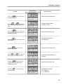
CFW-09 - QUICK PARAMETER REFERENCE
Parameters
Function
Adjustable Range
380-480 V Models
20 = 142 A
0 = 3.6 A
1=4A
21 = 180 A
2 = 5.5 A
55 = 211 A
5=9A
22 = 240 A
7 = 13 A
67 = 312 A
8 = 16 A
23 = 361 A
9 = 24 A
24 = 450 A
11 = 30 A
69 = 515 A
12 = 38 A
25 = 600 A
13 = 45 A
33 = 686 A
15 = 60 A
34 = 855 A
16 = 70 A
35 = 1140 A
17 = 86 A
36 = 1283 A
18 = 105 A
37 = 1710 A
82 = 1468 A
500-600 V Models
39 = 2.9 A 47 = 53 A
40 = 4.2 A 48 = 63 A
4=7A
49 = 79 A
6 = 10 A
25 = 600 A
41 = 12 A 72 = 652 A
42 = 14 A 73 = 794 A
43 = 22 A 76 = 897 A
44 = 27 A 78 = 978 A
45 = 32 A 79 = 1191A
46 = 44 A 81 = 1345 A
500-690 V Models
51 = 107 A 60 = 315 A
53 = 147 A 62 = 343 A
55 = 211 A 63 = 418 A
57 = 247 A 65 = 472 A
660-690 V Models
50 = 107 A
68 = 492 A
52 = 127 A
70 = 580 A
54 = 179 A
71 = 646 A
56 = 225 A
74 = 813 A
58 = 259 A
75 = 869 A
59 = 305 A
77 = 969 A
61 = 340 A
80 = 1220 A
64 = 428 A
Special Models
38 = 2 A
29 = 400 A
66 = 33 A
30 = 570 A
26 = 200 A 31 = 700 A
27 = 230 A 32 = 900 A
28 = 320 A
26
Factory
Setting
Unit
User's
Setting
Page
CFW-09 - QUICK PARAMETER REFERENCE
Parameters
P296 (1) (11)
P297
(1) (2)
Function
Factory
Setting
Adjustable Range
Inverter Rated Voltage
0 = 220-230 V
0 = for models
(Rated Input Voltage)
1 = 380 V
220-230 V
2 = 400-415 V
3 = for models
3 = 440-460 V
380-480 V
4 = 480 V
6 = for models
5 = 500-525 V
500-600 V and
6 = 550-575 V
500-690 V
7 = 600 V
8 = for models
8 = 660-690 V
660-690 V
0 = 1.25
2 = 5.0
Switching Frequency
Unit
-
User's
Page
Setting
Attention!
195
Refer to
item
3.2.3 to
do the
voltage
selection
kHz
195
1 = 2.5
2 = 5.0
3 = 10.0
DC Braking
P300
DC Braking Time
0.0 to 15.0
0.0
s
196
P301
DC Braking Start Speed
0 to 450
30
rpm
197
P302
DC Braking Voltage
0.0 to 10.0
2.0
%
197
Skip Speed
P303
Skip Speed 1
P133 to P134
600
rpm
197
P304
Skip Speed 2
P133 to P134
900
rpm
197
P305
Skip Speed 3
P133 to P134
1200
rpm
197
P306
Skip Band
0 to 750
0
rpm
197
Serial Communication
P308 (1)
Inverter Address
1 to 30
1
-
198
P309 (1)
Fieldbus
0 = Disable
0 = Disable
-
198
1 = Profibus DP/DP-V1 2 I/O
2 = Profibus DP/DP-V1 4 I/O
3 = Profibus DP/DP-V1 6 I/O
4 = DeviceNet 2 I/O
5 = DeviceNet 4 I/O
6 = DeviceNet 6 I/O
7 = EtherNet/IP 2 I/O
8 = EtherNet/IP 4 I/O
9 = EtherNet/IP 6 I/O
10 = DeviceNet Drive Profile
P310 (1)
P312 (1)
STOP Detection in a Profibus
0 = Off
Network
1 = On
Type of Serial Protocol
0 = WBUS Protocol
0 = Off
0 = WEG Protocol
198
-
199
1 = Modbus-RTU, 9600 bps,
no parity
2 = Modbus-RTU, 9600 bps,
odd parity
3 = Modbus-RTU, 9600 bps,
even parity
4 = Modbus-RTU, 19200 bps,
no parity
5 = Modbus-RTU, 19200 bps,
odd parity
27
CFW-09 - QUICK PARAMETER REFERENCE
Parameters
Function
Factory
Setting
Adjustable Range
Unit
User's
Setting
Page
6 = Modbus-RTU, 19200 bps,
even parity
7 = Modbus-RTU, 38400 bps,
no parity
8 = Modbus-RTU, 38400 bps,
odd parity
9 = Modbus-RTU, 38400 bps,
even parity
P313 (1) (8)
Type of disabling by E28/E29/E30
0 = Disable via Start/Stop
0 = Disable via Start/Stop
-
199
0.0 = Disabled
s
200
1 = Disable via General
Enable
2 = Not Used
3 = Changes to LOCAL 1
4 = Changes to LOCAL 2
5 = Causes Fatal Error
P314 (1)
P318
Time for Serial Watchdog
0.0 = Disable
Action
0.1 to 999.0 = Enable
Watchdog detection for the
0 = Off
PLC board
1 = On
0 = Off
200
Flying Start/Ride-Through
P320 (1)
Flying Start/Ride-Through
0 = Inactive
0 = Inactive
-
200
178 to 282 (P296 = 0)
252
V
200
307 to 487 (P296 = 1)
436
324 to 513 (P296 = 2)
459
356 to 564 (P296 = 3)
505
388 to 615 (P296 = 4)
550
425 to 674 (P296 = 5)
602
466 to 737 (P296 = 6)
660
486 to 770 (P296 = 7)
689
559 to 885 (P296 = 8)
792
178 to 282 (P296 = 0)
245
V
201
307 to 487 (P296 = 1)
423
324 to 513 (P296 = 2)
446
356 to 564 (P296 = 3)
490
388 to 615 (P296 = 4)
535
425 to 674 (P296 = 5)
588
466 to 737 (P296 = 6)
644
486 to 770 (P296 = 7)
672
V
202
1 = Flying Start
2 = Flying Start/Ride-Through
3 = Ride-Through
P321 (6)
P322
(6)
P323 (6)
28
Ud Line Loss Level
Ud Ride-Through
Ud Line Recover Level
559 to 885 (P296 = 8)
773
178 to 282 (P296 = 0)
267
307 to 487 (P296 = 1)
461
324 to 513 (P296 = 2)
486
356 to 564 (P296 = 3)
534
388 to 615 (P296 = 4)
583
425 to 674 (P296 = 5)
638
466 to 737 (P296 = 6)
699
486 to 770 (P296 = 7)
729
CFW-09 - QUICK PARAMETER REFERENCE
Parameters
Function
Factory
Setting
Adjustable Range
559 to 885 (P296 = 8)
838
Unit
User's
Setting
Page
P325
Ride-Through Proportional Gain
0.0 to 63.9
22.8
-
P326
Ride-Through Integral Gain
0.000 to 9.999
0.128
-
203
203
P331
Voltage Ramp
0.2 to 60.0
2.0
s
204
P332
Dead Time
0.1 to 10.0
1.0
s
204
0 = Instances 20/70
0 = Instances 20/70
-
206
DeviceNet Drive Profile
P335
DeviceNet I/O Instances
1 = Instances 21/71
2 = Instances 100/101
3 = Instances 102/103
P336
Input Word #3
0 to 749
0
-
206
P337
Input Word #4
0 to 749
0
-
206
P338
Input Word #5
0 to 749
0
-
206
P339
Input Word #6
0 to 749
0
-
206
P340
Input Word #7
0 to 749
0
-
206
P341
Output Word #3
0 to 749
0
-
207
P342
Output Word #4
0 to 749
0
-
207
P343
Output Word #5
0 to 749
0
-
207
P344
Output Word #6
0 to 749
0
-
207
P345
Output Word #7
0 to 749
0
-
207
P346
I/O Words Quantity
2 to 7
2
-
207
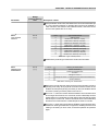
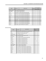
PARAMETERS FOR CRANE APPLICATIONS AND FOR MASTER/SLAVE FUNCTION - P351 to P399
Logic for the Mechanical Braking Operation
P351 (1)
Delay for E33
0.0 to 99.9
99.9
s
208
P352 (1)
Delay for E34
0 to 999
999
s
208
P353 (1)
Delay for N < Nx - Brake Activation 0.0 to 20.0
0.0
s
208
P354 (1)
Delay for Resetting the Integrator
0.0 to 10.0
2.0
s
208
0.0 to 10.0
1.0
s
208
0.0 to 10.0
0.0
s
209
of the Speed Regulator
P355 (1)
Delay for Accepting New
“Start/Stop” Commands
P356 (1)
Delay for Ramp Enable
Indication of the Torque Current Polarity
P357 (1)
P358
(1)
Torque Current (Iq) Filter
0.00 to 9.99
0.00
s
209
Torque Current (Iq) Hysteresis
0.00 to 9.99
2.00
%
209
0 = Off
0 = Off
-
209
Parameters for Load Detection
P361 (1)
Load Detection
1 = On
P362 (1)
Stabilization Speed
0 to P134
90
rpm
209
P363 (1)
Stabilization Time
0.1 to 10.0
0.1
s
210
P364 (1)
Slack Cable Time
0.0 to 60.0
0.0
s
210
P365 (1)
Slack Cable Level
0.0 to 1.3 x P295
0.1 x P295
A
210
(1)
Lightweight Level
0.0 to 1.3 x P295
0.3 x P295
A
210
P367 (1)
Overweight Level
0.0 to 1.8 x P295
1.1 x P295
A
210
P368 (1)
Speed Reference Gain
1.000 to 2.000
1.000
-
210
P366
Fx
P369 (2) (11)
Frequency Fx
0.0 to 300.0
4.0
Hz
210
P370
Hysteresis for Fx
0.0 to 15.0
2.0
Hz
213
DC Braking
P371
DC Braking Time at Start
0.0 to 15.0
0.0
s
213
P372
DC Braking Current Level
0.0 to 90.0
40.0
%
213
29
CFW-09 - QUICK PARAMETER REFERENCE
Parameters
Function
Factory
Setting
Adjustable Range
Unit
User's
Setting
Page
VVW Control
P398 (1)
P399 (1) (2)
Slip Compensation During
0 = Off
Regeneration
1 = On
Motor Rated Efficiency
50.0 to 99.9
1 = On
-
213
According to
%
213
V
214
the motor rated
power factor
(P404)
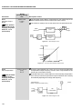
MOTOR PARAMETERS
P400 to P499
Motor Nameplate Data
P400 (1) (6)
P401
(1) (12)
P402 (1) (2) (11)
Motor Rated Voltage
0 to 690
Motor Rated Current
(0.0 to 1.30) x P295
Motor Rated RPM
0 to 18000
P296
(12)
1.0 x P295
1750 (1458)
A
214
rpm
214
Hz
214
-
214
(P202 = 0, 1, 2 and 5)
0 to 7200 (P202 = 3 and 4)
P403
(1) (11)
Motor Rated Frequency
0 to 300 (P202 = 0,1,2 and 5) 60 (50)
30 to 120 (P202 = 3 and 4)
P404 (1)
Motor Rated hp
0 = 0.33 hp/0.25 kW
1 = 0.50 hp/0.37 kW
2 = 0.75 hp/0.55 kW
3 = 1.0 hp/0.75 kW
4 = 1.5 hp/1.1 kW
5 = 2.0 hp/1.5 kW
6 = 3.0 hp/2.2 kW
7 = 4.0 hp/3.0 kW
8 = 5.0 hp/3.7 kW
9 = 5.5 hp/4.0 kW
10 = 6.0 hp/4.5 kW
11 = 7.5 hp/5.5 kW
12 = 10.0 hp/7.5 kW
13 = 12.5 hp/9.0 kW
14 = 15.0 hp/11.0 kW
15 = 20.0 hp/15.0 kW
16 = 25.0 hp/18.5 kW
17 = 30.0 hp/22.0 kW
18 = 40.0 hp/30.0 kW
19 = 50.0 hp/37.0 kW
20 = 60.0 hp/45.0 kW
21 = 75.0 hp/55.0 kW
22 = 100.0 hp/75.0 kW
23 = 125.0 hp/90.0 kW
24 = 150.0 hp/110.0 kW
25 = 175.0 hp/130.0 kW
26 = 180.0 hp/132.0 kW
27 = 200.0 hp/150.0 kW
28 = 220.0 hp/160.0 kW
29 = 250.0 hp/185.0 kW
30 = 270.0 hp/200.0 kW
31 = 300.0 hp/220.0 kW
32 = 350.0 hp/260.0 kW
30
4 = 1.5 hp/1.1 kW
CFW-09 - QUICK PARAMETER REFERENCE
Parameters
Function
Factory
Setting
Adjustable Range
Unit
User's
Setting
Page
33 = 380.0 hp/280.0 kW
34 = 400.0 hp/300.0 kW
35 = 430.0 hp/315.0 kW
36 = 440.0 hp/330.0 kW
37 = 450.0 hp/335.0 kW
38 = 475.0 hp/355.0 kW
39 = 500.0 hp/375.0 kW
40 = 540.0 hp/400.0 kW
41 = 600.0 hp/450.0 kW
42 = 620.0 hp/460.0 kW
43 = 670.0 hp/500.0 kW
44 = 700.0 hp/525.0 kW
45 = 760.0 hp/570.0 kW
46 = 800.0 hp/600.0 kW
47 = 850.0 hp/630.0 kW
48 = 900.0 hp/670.0 kW
49 = 1100.0 hp/820.0 kW
50 = 1600.0 hp/1190.0 kW
P405 (1)
Encoder PPR
100 to 9999
1024
ppr
215
P406 (1)
Motor Ventilation Type
0 = Self Ventilated
0 = Self Ventilated
-
215
According to the
-
216
0 = No
-
216
0.000
217
1 = Separate Ventilation
2 = Optimal Flux
3 = Increased Protection
P407 (1) (2)
Motor Rated Power Factor
0.50 to 0.99
motor rated power
(P404)
Measured Parameters
P408 (1)
Self-Tuning
0 = No
1 = No Rotation
2 = Run for Imr
3 = Run for Tm
4 = Estimate Tm
P409 (1)
Motor Stator Resistance (Rs)
0.000 to 77.95
P410
Motor Magnetizing Current (Imr)
(0.0 to 1.25) x P295
0.0
A
P411 (1)
Motor Flux Leakage Inductance ( LS) 0.00 to 99.99
0.00
mH
218
LR/RR Constant (Rotor Time
0.000 to 9.999
0.000
s
218
0.00 to 99.99
0.00
s
219
P412
218
Constant (Tr))
P413 (1)
Tm Constant (Mechanical Time
Constant)
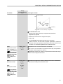
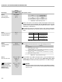
SPECIAL FUNCTION PARAMETERS P520 to P538
PID Regulator
P520
PID Proportional Gain
0.000 to 7.999
1.000
-
223
P521
PID Integral Gain
0.000 to 7.999
0.043
-
223
P522
PID Differential Gain
0.000 to 3.499
0.000
-
223
P523
PID Ramp Time
0.0 to 999
3.0
s
223
P524 (1)
Selection of PID Feedback
0 = AI2 (P237 to P240)
0 = AI2 (P237 to P240)
-
223
1 = AI3 (P241 to P244)
P525
PID Setpoint
0.0 to 100.0
0.0
%
224
P526
Process Variable Filter
0.0 to 16.0
0.1
s
224
31
CFW-09 - QUICK PARAMETER REFERENCE
Parameters
Function
Factory
Setting
Adjustable Range
P527
PID Action
0 = Direct
P528
Process Variable Scale Factor
P529
P530
Unit
User's
Setting
Page
0 = Direct
-
224
0 to 9999
1000
-
Decimal Point of Proc. Var.
0 to 3
1
Engineering Unit of Proc. Var. 1
32 to 127 (ASCII)
37 = %
-
226
32 = blank
-
226
32 = blank
-
226
90.0
%
226
1 = Reverse
225
225
A, B, ... , Y, Z
0, 1, ... , 9
#, $, %, (, ), *, +, ...
P531
Engineering Unit of Proc. Var. 2
32 to 127 (ASCII)
A, B, ... , Y, Z
0, 1, ... , 9
#, $, %, (, ), *, +, ...
P532
Engineering Unit of Proc. Var. 3
32 to 127 (ASCII)
A, B, ... , Y, Z
0, 1, ... , 9
#, $, %, (, ), *, +, ...
P533
Value of Proc. Var. X
0.0 to 100
P534
Value of Proc. Var. Y
0.0 to 100
10.0
%
226
P535
Wake Up Band
0 to 100
0
%
227
P536 (1)
Automatic Setting of P525
0 = Active
0 = Active
-
227
1 to 100
1
%
227
0.0 to 50.0
1.0
%
227
1 = Inactive
P537
Hysteresis for Set point =
Process Variable
P538
Hysteresis for VPx/VPy
Notes presented on Quick Parameter Description:
(1) Parameter can be changed only with the inverter disabled (motor stopped).
(2) Values may change as a function of the “Motor Parameters”.
(3) Values may change as a function of P413 (Tm Constant - obtained during
Self-tuning).
(4) Values may change as a function of P409 and P411 (obtained during Selftuning).
(5) Values may change as a function of P412 (Tr Constant - obtained during
Self-tuning).
(6) Values may change as a function of P296.
(7) Values may change as a function of P295.
(8) Values may change as a function of P203.
(9) Values may change as a function of P320.
(10) User’s Standard (for new inverters) = without parameter.
(11) The inverter will be delivered with settings according to the market,
considering the HMI language, V/F 50 Hz or 60 Hz and the required voltage.
The reset of the standard factory setting may change the parameters related
to the frequency (50 Hz/60 Hz). Values within parenthesis mean the factory
setting for 50 Hz.
(12) The maximum value of P156 and P401 is 1.8 x P295 for model 4.2 A/500600 V and 1.6 x P295 for models 7 A and 54 A/220-230 V; 2.9 A and 7 A/500600 V; 107 A, 147 A and 247 A/500-690 V; 100 A, 127 A and 340 A/660-690 V.
32
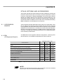
CFW-09 - QUICK PARAMETER REFERENCE
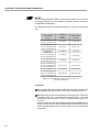
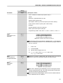
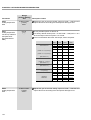
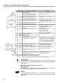
Parameters that
affect others
when set
P203
P295
P296
P320
P401
P402
P403
P404
P406
Parameters that are affected
and modified automatically
P220, P222, P223, P224, P225,
P226, P227, P228, P237, P263,
P264, P265, P279, P313
P156, P157, P158, P169 (V/F),
P290, P365, P366, P367
P151, P153, P321, P322, P323
P400
P214
P156, P157, P158
P297
P122, P123, P124, P125, P126,
P127, P128, P129, P130, P131,
P133, P134, P135, P208, P288,
P289
P369, P402
P399, P407
P156, P157, P158
Condition where it occurs
During the
During
oriented
normal
start-up
operation
NO
YES
NO
YES
YES
YES
NO
YES
YES
YES
YES
NO
YES
NO
NO
YES
YES
YES
YES
NO
YES
NO
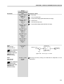
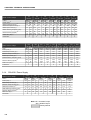
Table 1 - Interdependence among parameters: parameters that change the settings of
others when modified versus parameters that are automatically modified as a function of a
parameter setting (during start-up and/or normal operation)
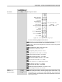
II. Fault Messages
Display
Description
Page
E00
Output Overcurrent/Short-Circuit
228
E01
DC Link Overvoltage
228
E02
DC Link Undervoltage
228
E03
Power Supply Undervoltage/Phase Loss
229
Inverter Overtemperature/Pre-charge Circuit
229
(*)
E04
Failure
E05
Output Overload (I x t Function)
229
E06
External Fault
229
E07
Encoder Fault
229
Valid for P202 = 4 (Vector with Encoder)
E08
CPU Error (watchdog)
229
E09
Program Memory Error
229
E10
Error in the Copy Function
229
E11
Output Ground Fault
229
E12
Dynamic Braking Resistor Overload
230
E13
Motor or Encoder with Inverted Wires
(Self-Tuning) (Valid for P202 = 4)
230
E15
Motor Phase Loss
E17
Overspeed Fault
230
E24
Programming Error
230
Serial communication error
230
E28 to E30
230
E31
Keypad Connection Fault
230
E32
Motor Overtemperature
230
E33
Speed without control
230
E34
Long period at torque limitation
230
E41
Self-Diagnosis Fault
230
E70
Internal DC Supply Undervoltage
231
E71
PLC Watchdog Error
231
(*) E04 can be "Pre-charge Circuit Failure" only in the following models:
86 A/380-480 V, 70 A/220-230 V, 44 A/500-600 V and for all 500-690 V and
660-690 V models. E04 can also occur when signal with inverted polarity is applied
at analog inputs AI1/AI2. The E04 fault message can also occur in the models up to
130 A/ 200-230 V, 142 A/380-480 V and 63 A/500-600 V when the temperature at
the heatsink is lower than -10 ºC.
33
CFW-09 - QUICK PARAMETER REFERENCE
III. Other Messages
Display
rdy
Inverter is Ready to be Enabled
run
Inverter is Enabled
Sub
dCbr
34
Description
Power Supply Voltage is Too Low for the Inverter Operation
(Undervoltage)
Inverter in DC Braking Mode. (Refer to P300)
CHAPTER
1
SAFETY NOTICES
This Manual contains all necessary information for the correct installation
and operation of the CFW-09 Variable Frequency Inverter.
The CFW-09 Instruction Manual has been written for qualified personnel
with suitable training or technical qualifications to operate this type of
equipment.
1.1 SAFETY NOTICES IN
THE MANUAL
The following Safety Notices will be used in this Manual:
DANGER!
If the recommended Safety Instructions are not strictly observed, it can lead
to serious or fatal injuries of personnel and/or equipment damage.
ATTENTION!
Failure to observe the recommended Safety Procedures can lead to material damage.
NOTE!
The content of this Manual supplies important information for the correct
understanding of operation and proper performance of the equipment.
1.2 SAFETY NOTICES
ON THE PRODUCT
The following symbols may be attached to the product, serving as Safety
Notice:
High Voltages.
Components are sensitive to electrostatic discharge. Do not touch
them without following proper grounding procedures.
Mandatory connection to ground protection (PE).
Shield connection to ground.
1.3 PRELIMINARY
RECOMMENDATIONS
DANGER!
Only qualified personnel should plan or implement the installation, startup,
operation and maintenance of this equipment. Personnel must review this
entire Manual before attempting to install, operate or troubleshoot the
CFW-09.
These personnel must follow all safety instructions included in this Manual
and/or defined by local regulations.
Failure to comply with these instructions may result in personnel injury and/
or equipment damage.
35
CHAPTER 1 - SAFETY NOTICES
NOTE!
In this Manual, qualified personnel are defined as people that are trained to:
1. Install, ground, power up and operate the CFW-09 according to this Manual
and the local required safety procedures;
2. Use of safety equipment according to the local regulations;
3. Administer Cardio Pulmonary Resuscitation (CPR) and First Aid.
DANGER!
Always disconnect the supply voltage before touching any electrical component
inside the inverter.
Many components are charged with high voltages, even after the incoming AC
power supply has been disconnected or switched OFF. Wait at least 10 minutes
for the total discharge of the power capacitors.
Always connect the frame of the equipment to the ground (PE) at the suitable
connection point.
ATTENTION!
All electronic boards have components that are sensitive to electrostatic
discharges. Never touch any of the electrical components or connectors without
following proper grounding procedures. If necessary to do so, touch the properly
grounded metallic frame or use a suitable ground strap.
Do not apply High Voltage (High Pot) Test on the Inverter!
If this test is necessary, contact WEG.
NOTE!
Inverters can interfere with other electronic equipment. In order to reduce this
interference, adopt the measures recommended in chapter 3 “Installation and
Connection”.
NOTE!
Read this entire Manual carefully and completely before installing or operating
the CFW-09.
36
CHAPTER
2
GENERAL INFORMATION
This chapter defines the contents and purpose of this manual and describes
the main characteristics of the CFW-09 frequency inverter. Identification of
the CFW-09, receiving and storage requirements are also provided.
2.1 ABOUT THIS MANUAL
This Manual is divided into 9 Chapters, providing information to the user on
how to receive, install, start-up and operate the CFW-09:
Chapter 1: Safety Notices;
Chapter 2: General Information and Receiving the CFW-09;
Chapter 3: Information about the CFW-09 physical installation, electrical
connection (power and control circuit) and installation of optional
devices;
Chapter 4: Keypad (HMI) Operation (Human-Machine Interface - keyboarddisplay);
Chapter 5: Start-up (Step-by-step);
Chapter 6: Detailed Programming Parameters Description;
Chapter 7: Diagnostics, troubleshooting, cleaning instructions and preventive
maintenance;
Chapter 8: Technical description of CFW-09 optional devices and
accessories;
Chapter 9: Technical specifications (electrical and mechanical).
This Manual provides information for the correct use of the CFW-09. The
CFW-09 is very flexible and allows for the operation in many different modes
as described in this manual.
As the CFW-09 can be applied in several ways, it is impossible to describe
here all of the application possibilities. WEG does not accept any
responsibility when the CFW-09 is not used according to this Manual.
No part of this Manual may be reproduced in any form, without the written
permission of WEG.
2.2 SOFTWARE VERSION
It is important to note the Software Version installed in the Version CFW-09,
since it defines the functions and the programming parameters of the inverter.
This Manual refers to the Software version indicated on the inside cover. For
example, the Version 1.0X applies to versions 1.00 to 1.09, where “X” is a
variable that will change due to minor software revisions. The operation of
the CFW-09 with these software revisions are still covered by this version of
the Manual.
The Software Version can be read in the Parameter P023.
2.3 ABOUT THE CFW-09
The CFW-09 is a high performance Variable Frequency Inverter that permits
the control of speed and torque of a three-phase AC induction motor. The
technological advantage of the CFW-09 is due to the “Vectrue” technology
that provides the following benefits:
Programmable scalar (volts/Hz) or Vector Control with the same product;
Vector Control can be programmed for “Sensorless” (that means that
standard motors can be controlled without encoder feedback), or “Closed
Loop” (with an encoder attached to the motor shaft);
37
CHAPTER 2 - GENERAL INFORMATION
The Sensorless Vector Control permits high torques and quick response,
even at very low speeds and during the starting of the motor;
The “Optimal Braking” function allows controlled motor braking without using
a Dynamic Braking (DB) resistor;
“Self-tuning” auto-tune function with Vector Control, permitting automatic setting
of the control regulators and control parameters by means of the automatic
identification of the motor and the load parameters.
Technical specifications for each model of CFW-09 are described in chapter 9.
The block diagram below gives a general view of the CFW-09:
= DC Link choke connection (optional)
only from size 2 and up.
= DC Link connection.
= DB resistor connection. Up to size 7
only. Option for sizes 4 to 7.
Precharge
Power
Supply
Motor
Capacitor
Bank
Three-phase
rectifier
IGBT
Inverter
RFI filter
PE
PE
DC Link
Sensors:
- Ground fault
- Phase-fault
Feedbacks:
- voltage
-current
= Phase-fault only
from size 3 and up.
Modbus-RTU
POWER
CONTROL
PC
SuperDrive Software
Internal electronics power supplies and
control/power interfaces
RS-232
(optional)
Keypad
(remote)
Keypad
Digital
Inputs
(DI1 ... DI6)
Analog
Inputs
(AI1 ... AI2)
"CC9"
Control
Board w/
32 bits
"RISC"
CPU
EBA/EBB EXPANSION:
(optional)
- isolated RS-485
- 1 digital input
1 x 14bit anal. input
A
2 x 14bit anal. outputs
{
B
{
1 isola. 4 to 20 mA In.
2 isola. 4 to 20 mA out.
- 2 digital outputs
- 1 encoder In/Out.
- 1 PTC input
FIELDBUS (Optional):
- Profibus DP
- DeviceNet
- EtherNet/IP
PC
PLC
DCS
External
Control
Analog
Outputs
(AO1 ... AO2)
Relay
Outputs
(RL1 ... RL3)
Human - Machine Interface
Figure 2.1 - CFW-09 block diagram
38
CHAPTER 2 - GENERAL INFORMATION
2.4 CFW-09 IDENTIFICATION LABEL AND CODE NUMBER
Serial Number
WEG Part
Number
Software
Revision
CFW-09 Model
Nominal Input Data
(Phase, Current and Frequency)
Nominal Output Data
(Voltage, Frequency)
Nominal Output Current and
Switching Frequency for VT and
CT Loads
Location of the CFW-09 Nameplate:
FRONT VIEW
VIEW-A
Figure 2.2 - CFW-09 identification
39
40
WEG
Series 09
Frequency
Inverter
CFW-09
500-690 V:
0107 = 107 A
0147 = 147 A
0211 = 211 A
0247 = 247 A
0315 = 315 A
0343 = 343 A
0418 = 418 A
0472 = 472 A
380-480 V:
0003 = 3.6 A
0004 = 4 A
0005 = 5.5 A
0009 = 9 A
0013 = 13 A
0016 = 16 A
0024 = 24 A
0030 = 30 A
0038 = 38 A
0045 = 45 A
0060 = 60 A
0070 = 70 A
0086 = 86 A
0105 = 105 A
0142 = 142 A
0180 = 180 A
0211 = 211 A
0240 = 240 A
0312 = 312 A
0361 = 361 A
0450 = 450 A
0515 = 515 A
0600 = 600 A
T
Three-phase
power
supply.
3848
3848 =
380-480 V
2223 =
220-230 V
5060 =
500-600 V
5069 =
500-690 V
6669 =
660-690 V
Power
supply
voltage:
E
P = Portuguese
E = English
S = Spanish
Manual
language:
O
__
Enclosure
degree of
protection:
__
__
Blank =
Standard
RB =
Regenerative
Converter
(Active Front
end unit).
DB =
Dynamic
Braking
(Refer to
chapter 8)
Keypad (HMI): Braking:
Blank =
S = standard
Standard
O = with options
IL = Keypad
(refer to note)
Blank =
LED display
Standard
N4 = NEMA 4 only
SI = without
IP56
keypad
(Refer to
(Refer to
chapter 8)
note)
Options:
__
Blank = Standard
A1 = EBA Board
Complete
B1 = EBB Board
Complete
C1 = EBC1
Board
Complete
E1 = EBE Board
complete
P1 = PLC 1.01
Board
P2 = PLC2.00
Board
Refer to
chapter 8 for
other
Configurations
Expansion
Boards:
__
__
Fieldbus
Special
Communication Hardware:
Boards:
Blank =
Blank = Standard Standard
DN = DeviceNet HN = Without
PD = Profibus DC Link
DP
inductor
DD = DeviceNet (only valid for
Profile
500-690 V and
EN = EtherNet/IP 660-690 V
V1 = Profibus
models)
DP-V1
HD = DC Link
supply (refer
to chapter 8)
HC, HV = DC
Link inductor
(Refer to
chapter 8)
(Refer to
note)
__
Blank =
Standard
S1 to Sn =
Special
Software
Version
SF = Metasys
N2 Protocol
Special
Software:
Note:
The option field (S or O) defines if the CFW-09 is a standard version or if it is equipped with any optional devices. If the standard version is required, the code ends here. The model
code number always has the letter Z at the end. For example:
CFW090045T2223ESZ = Standard 45 A CFW-09 inverter - three phase input at 220-230 V, with the Manual in English.
If the CFW-09 is equipped with any optional devices, you must fill out the fields in accordance to the optional devices desired in the correct sequence up to the last optional device
desired, then the model code number is completed with the letter Z.
Thus, for instance, if a product of the example above is required with an EBA expansion board, indicate:
CFW090045T2223EOA1Z = 45 A CFW-09 inverter – three-phase input at 220-230 V, with the manual in English and with the optional EBA.01 board.
Note:
- For rated output current specification of variable torque (VT), refer to chapter 9.
- The rated output current indicated for the models 500-690 V is only valid for 500 V to 600 V supply.
- For rated output current specification (CT and VT) of the models with supply voltage higher than 600 V, refer to chapter 9.
660-690 V:
0100 = 100 A
0127 = 127 A
0179 = 179 A
0225 = 225 A
0259 = 259 A
0305 = 305 A
0340 = 340 A
0428 = 428 A
500-600 V:
0002 = 2.9 A
0004 = 4.2 A
0007 = 7 A
0010 = 10 A
0012 = 12 A
0014 = 14 A
0022 = 22 A
0027 = 27 A
0032 = 32 A
0044 = 44 A
0053 = 53 A
0063 = 63 A
0079 = 79 A
220-230 V:
0006 = 6 A
0007 = 7 A
0010 = 10 A
0013 = 13 A
0016 = 16 A
0024 = 24 A
0028 = 28 A
0045 = 45 A
0054 = 54 A
0070 = 70 A
0086 = 86 A
0105 = 105 A
0130 = 130 A
Output rated current constant torque CT:
0016
HOW TO SPECIFY THE CFW-09 MODEL:
End of Code
(refer to note)
Z
CHAPTER 2 - GENERAL INFORMATION
The standard product is defined as described here:
Degree of protection:
NEMA 1/ IP20: 3.6 A to 240 A/380-480 V models and all 220-230 V and
500-600 V models.
Protected chassis / IP20: 361 A to 600 A/380-480 V models and all 500690 V and 660-690 V models.
Human Machine Interface:
HMI-CFW09-LCD (with LED and LCD displays)
Braking:
DB Transistor for DB Resistor braking incorporated in the following models:
6 A to 45 A/220-230 V
3.6 A to 30 A/380-480 V
2.9 A to 14 A/500-600 V
DC Link:
The DC Link choke is included in the standard product for 44 A, 53 A, 63 A
and 79 A/500-600 V, all models 500-690 V and 660-690 V models.
DB Transistor can be incorporated as an option in the following models:
54 A to 130 A/220-230 V
38 A to 142 A/380-480 V
22 A to 79 A/500-600 V
Models 180 A to 600 A/380-480 V, 107 A to 472 A/500-690 V and 100 A to
428 A/660-690 V, do not have the capability to use an internal DB Transistor.
In this case, use the external DB Transistor option (refer to item 8.10.3 Dynamic Braking Module - DBW-01 and DBW-02).
NOTE!
It is necessary to connect an external braking resistor regardless if the DB
Transistor is built in, optional built in or an external module (DBW).
2.5 RECEIVING AND
STORAGE
The CFW-09 is supplied in cardboard boxes up to size 3 (refer to item 9) and for
models above, the packing will be with wood pallet and wood box.
The outside of the packing container has a nameplate that is identical to that on
the CFW-09. Please check if the nameplate data matches the ordered ones.
The boxes up to size 7 must be placed and opened on a table (sizes above 3
with the help of two persons).
Open the box, remove the cardboard or expanded polystyrene protection.
The boxes of sizes above 7 must be opened on the floor. Open the wood box,
remove the expanded polystyrene protection. The CFW-09 must be handled
with hoist.
Check if:
CFW-09 nameplate data matches the purchase order;
The equipment has not been damaged during transport.
If any problem is detected, contact the carrier immediately.
If the CFW-09 is not to be installed immediately, store it in a clean and dry
room (Storage temperatures between -25°C and 60°C). Cover it to prevent
dust, dirt or other contamination of the inverter.
ATTENTION!
If the inverter is stored for long periods, we recommend to power it up once a
year during 1 hour. For 220-230 V and 380-480 V models apply supply voltage
of approximately 220 Vac, three-phase or single-phase input, 50 or 60 Hz,
without connecting motor at output. After this energization, wait 24 hours
before installing it. For 500-600 V, 500-690 V and 660-690 V models use the
same procedure applying a voltage between 300 and 330 Vac to the inverter
input.
41
CHAPTER
3
INSTALLATION AND CONNECTION
This chapter describes the procedures for the electrical and mechanical
installation of the CFW-09.
These guidelines must be followed for proper CFW-09 operation.
3.1 MECHANICAL
INSTALLATION
3.1.1 Environment Conditions
The location of the CFW-09 installation is an important factor to assure
good performance and high product reliability.
For proper installation of the inverter, we make the following
recommendations:
Avoid direct exposure to sunlight, rain, high moisture and sea air..
Avoid exposure to gases or explosive or corrosive liquids.
Avoid exposure to excessive vibration, dust, oil or any (conductive
particles or materials).
Allowed environmental conditions:
Temperature: 0 ºC to 40 ºC (32 ºF to 104 ºF) - nominal conditions.
From 40 ºC to 55 ºC (104 ºF to 131 ºF) - with 2 % current derating for
each 1 ºC (33.8 ºF) degree above 40 ºC (104 ºF).
Relative Air Humidity: 5 % to 90 %, non-condensing.
Maximum Altitude: 1000 m (3.300 ft) – nominal conditions.
From 1000 m to 4000 m (3.300 ft to 13.200 ft) – with 1 % current
reduction for each 100 m (330 ft) above 1000 m (3.300 ft).
Pollution Degree: 2 (according to EN50178 and UL508C) (It is not
allowed the presence of water, condensation or conductive dust/
particles in the air).
External dimensions and mounting holes are according to figure 3.1 and
table 3.1.
3.1.2 Dimensional of CFW-09
Sizes 1 and 2
P
L
B
H
A
D
C
Sizes 3 to 8, 8E
Sizes 9, 10 and 10E
A
A
Sizes 3 to 10, 8E and 10E
H
D
D
C
C
Figure 3.1 - Mounting dimensional drawings of CFW-09
42
P
L
B
B
A
CHAPTER 3 - INSTALLATION AND CONNECTION
Model
Size 1
Size 2
Size 3
Size 4
Size 5
Size 6
Size 7
Size 8
Size 8E
Size 9
Size 10
Size 10E
Height
H
mm
(in)
Width
L
mm
(in)
Depth
P
mm
(in)
A
mm
(in)
C
mm
(in)
D
mm
(in)
Mounting
Screw
mm
(in)
210
143
196
121
180
11
9.5
M5
3.5
(8.27)
(5.63)
(7.72)
290
182
196
(4.76)
(7.09)
(0.43)
(0.37)
(3/16)
(7.7)
161
260
10.5
9.5
M5
(11.42)
(7.16)
6.0
(7.72)
(6.34)
(10.24)
(0.41)
(0.37)
(3/16)
(13.2)
390
223
274
150
375
36.5
5
M6
19.0
(15.35)
(8.78)
(10.79)
(5.90)
(14.76)
(1.44)
(0.20)
(1/4)
(41.9)
475
250
274
150
450
50
10
M6
22.5
(18.70)
(9.84)
(10.79)
(5.90)
(17.72)
(1.97)
(0.39)
(1/4)
(49.6)
550
335
274
200
525
67.5
10
M8
41
(21.65)
(13.19)
(10.79)
(7.87)
(20.67)
(2.66)
(0.39)
(5/16)
(90.4)
675
335
300
200
650
67.5
10
M8
55
NEMA1/
(26.57)
(13.19)
(11.77)
(7.87)
(25.59)
(2.66)
(0.39)
(5/16)
(121.3)
IP20
835
335
300
200
810
67.5
10
M8
70
(32.87)
(154.3)
B
mm
(in)
Weight
Kg
(lb)
(13.19)
(12.20)
(7.87)
(31.89)
(2.66)
(0.39)
(5/16)
975
410
370
175
950
67.5
10
M8
100
(38.38)
(16.14)
(14.57)
(10.83)
(37.40)
(2.66)
(0.39)
(5/16)
(220.5)
1145
410
370
275
1120
67.5
10
M8
115
(45.08)
(253)
(16.14 )
(14.57)
(10.83)
(44.09)
(2.66)
(0.39)
(5/16)
1020
688
492
275
985
69
15
M10
216
(39.37)
(27.56)
(19.33)
(10.83)
(37.99)
(2.95)
(0.59)
(3/8)
(476.2)
1185
700
492
275
1150
69
15
M10
259
(46.65)
(27.56)
(19.33)
(10.83)
(45.27)
(2.95)
(0.59)
(3/8)
(571)
1185
700
582
275
1150
69
15
M10
310
(46.65)
(27.56)
(22.91)
(10.83)
(45.27)
(2.95)
(0.59)
(3/8)
(682)
Degree of
Protection
IP20
Table 3.1 - Installation data – Refer to item 9.1
3.1.3 Mounting Specifications For installing the CFW-09, leave at least the minimum free spaces around the
inverter according to figure 3.2. The dimensions of these free spaces are described
on table 3.2.
Install the inverter in the vertical position according to the following
recommendations:
1) Install the inverter on a flat surface.
2) Do not install heat sensitive components immediately above the inverter.
3) For the inverters 45 A to 130 A/220-230 V, 30 A to 600 A/380-480 V, 22 A
to 32 A/ 500-600 V, 44 A to 79 A/500-600 V, 107 A to 472 A/500-690 V and
100 A to 428 A/660-690 V:
- First partially tighten the bolts on the surface, then install the inverter
and screw-down the bolts.
4) For inverters 6 A to 28 A/220-230 V, 3.6 A to 24 A/380-480 V and 2.9 A to
14 A/500-600 V:
- Install the 2 bottom mounting bolts first, rest the inverter on the base and
then mount the 2 top bolts.
43
CHAPTER 3 - INSTALLATION AND CONNECTION
ATTENTION!
When inverters are installed side by side, maintain the minimum
recommended distance B. When inverters are installed top and bottom,
maintain the minimum recommended distance A + C and deflect the hot air
coming from inverter below.
ATTENTION!
Provide independent conduits for signal, control and power conductors (Refer
to item 3.2: Electrical Installation).
50 mm
2 in
A
B
B
C
Figure 3.2 - Free space for cooling
Model
CFW-09
A
mm (in)
B
mm (in)
C
mm (in)
40
(1.57)
30
(1.18)
50
(2)
100
(4)
40
(1.57)
130
(5.12)
6 A to 28 A/220-230 V
3.6 A to 24 A/380-480 V
2.9 A to 14 A/500-600 V
45 A to 130 A/220-230 V
30 A to 142 A/380-480 V
22 A to 79 A/500-600 V
180 A to 361 A/380-480 V
450 A to 600 A/380-480 V
107 A to 472 A/500-690 V
55 (2.17)
150
(6)
80
(3.15)
250
(10)
100 A to 428 A/660-690 V
Table 3.2 - Recommended free spaces
3.1.3.1 Mounting Inside a Panel When inverters are installed in panels or closed metallic boxes, adequate
cooling is required to ensure that the temperature around the inverter will
not exceed the maximum allowed temperature. Refer to Dissipated Power
in item 9.1.
For reference, table 3.3 shows the cooling airflow for each inverter model.
44
CHAPTER 3 - INSTALLATION AND CONNECTION
Inverter Cooling Method: Internal fan, flow direction from the bottom to the top.
CFW-09 Inverter Model
6 A to 13 A/220-230 V
3.6 A to 9 A/380-480 V
2.9 A to 14 A/500-600 V
16 A to 28 A/220-230 V
13 A to 24 A/380-480 V
45 A/220-230 V
30 A/380-480 V
54 A/220-230 V
38 A and 45 A/380-480 V
22 A to 32 A/500-600 V
70 A and 86 A/220-230 V
60 A and 70 A/380-480 V
105 A and 130 A/220-230 V
86 A and 105 A/380-480 V
44 A to 79 A/500-600 V
142 A/380-480 V
180 A to 240 A/380-480 V
107 A to 211 A/500-690 V
100 A to 179 A/660-690 V
312 A and 361 A/380-480 V
450 A to 600 A/380-480 V
247 A to 472 A/500-690 V
225 A to 428A/660-690 V
Size
CFM
I/s
m3/min
1
19
9
0.5
2
32
15
0.9
3
70
33
2.0
4
89
42
2.5
5
117
55
3.3
138
65
3.9
286
135
8.1
265
125
7.5
852
402
24.1
795
375
22.5
6
7
8
8E
8E
9
10
10E
10E
Table 3.3 - Cooling air flow requirements
3.1.3.2 Mounting on Surface
a) Sizes 1 and 2
Figure 3.3 shows the installation of the CFW-09 on a mounting plate.
b) Sizes 3 to 8
Figure 3.3 a) and b) - Mounting procedure for the CFW-09 on a surface
45
CHAPTER 3 - INSTALLATION AND CONNECTION
d) Positioning (for all Sizes)
c) Sizes 9 and 10
Air Flow
Figure 3.3 c) and d) - Mounting procedure for the CFW-09 on a surface
3.1.3.3
Mounting with the
Heatsink Through
a Surface
The CFW-09 can also be installed with the heatsink through the mounting
plate, as shown in figure 3.4.
In this case, refer to installation drawings shown in figure 3.4 c) and maintain
the distances indicated in table 3.4.
NOTE!
When installing the heatsink through the mounting surface, according to
figure 3.4, the degree of protection behind this surface is NEMA 1 / IP20.
NEMA1 rating does not protect against dust and water.
46
CHAPTER 3 - INSTALLATION AND CONNECTION
a) Sizes 1 and 2
Step 1
Step 2
Step3
Step 2
Step 3
4 mm (1/6 in) max.
Air
Flow
b) Sizes 3 to 8E
Step 1
Air
Flow
Kit-KMF
Top Support
4 mm (1/6 in) max.
Kit-KMF
Botton Support
c) Cutout Dimensions (Refer to table 3.4)
Sizes 3 to 8
Sizes 1 and 2
Figure 3.4 a) to c) - Mounting procedure for the CFW-09 with the heatsink through the mounting surface
47
CHAPTER 3 - INSTALLATION AND CONNECTION
CFW-09
Size
Size 1
Size 2
Size 3
Size 4
Size 5
Size 6
Size 7
Size 8
Size 8E
L1
mm
(in)
H1
mm
(in)
A1
mm
(in)
B1
mm
(in)
C1
mm
(in)
D1
mm
(in)
Emim.
Kit KMF (*)
mm
Through
(in) Surface Mounting
item nº
139
196
127
191
6
2.5
6
(5.47)
(7.72)
(5.00)
(7.52)
(0.24)
(0.10)
(0.24)
271
6
178
276
167
(7.00)
(10.87)
(6.57)
225
372
150
(7.00)
(14.64)
(6.57)
252
452
150
(9.92)
(17.79)
(5.91)
337
527
200
(13.27)
(20.75)
(7.87)
13.27
652
200
(13.27)
(25.67)
(7.87)
337
812
200
(13.27)
(31.97)
(7.87)
412
952
(16.22)
(37.48)
412
1122
(16.22)
(44.17)
275
(10.67) (0.24)
400
1150
14
10
(0.59)
(0.35)
14
10
(0.59)
(0.39)
14
10
(0.59)
(0.39)
68.5
(10.38) (38.58) (2.70)
275
8
(0.31)
68.5
(33.07) (2.70)
980
14
(0.59)
68.5
(26.77) (2.70)
840
8
(0.31)
68.5
(21.85) (2.70)
680
14
(0.59)
51
(18.90) (1.97)
555
6
(0.24)
37.5
(15.75) (1.44)
480
2.5
(0.10)
14
10
(0.59)
(0.39)
14
10
(0.59)
(0.39)
68.5
(10.83) (45.27) (2.70)
----------------------417102514
417102515
417102516
417102517
417102518
417102519
(*) The Through Surface Mounting kit (kit-KMF) is a set of supports for the CFW-09 as shown on
figure 3.4 b).
Table 3.4 - Cutout dimensions and kits for CFW-09 through surface mounting
3.1.4 Keypad (HMI) and
Cover Removal
a) Sizes 1 and 2
b) Sizes 3 to 8 and 8E
Screw
Figure 3.5 a) and b) – Keypad (HMI) and cover removal procedure
48
CHAPTER 3 - INSTALLATION AND CONNECTION
c) Sizes 9 and 10, 10E
Screw
Figure 3.5 c) – Keypad (HMI) and cover removal procedure
3.2 ELECTRICAL
INSTALLATION
DANGER!
The information below will be a guide to achieve a proper installation. Follow
also all applicable local standards for electrical installations.
DANGER!
Be sure that the AC input power is disconnected before making any terminal
connection.
DANGER!
The CFW-09 frequency inverter cannot be used as an emergency stop device.
Provide another devices for this function.
3.2.1 Power/Grounding
Terminals
The power connection terminals can be of different sizes and configurations,
depending on the inverter model as shown in figure 3.6.
Terminals:
R, S, T: AC supply line. Models up to 10 A at 220-230 V can be operated
with two phases (single-phase operation) without current derating. In this
case the AC supply can be connected to any 2 of the 3 input terminals.
U, V, W: Motor connection.
-UD: Negative pole of the DC Link circuit.
BR: Dynamic Braking resistor connection.
+UD: Positive pole of the DC Link circuit.
DCR: Connection to the external DC Link choke (optional).
PE: Ground Safety.
49
CHAPTER 3 - INSTALLATION AND CONNECTION
a) Size 1 models
b) Size 2 models
c) Size 3, 4 and 5 models
d) Size 6 and 7 (220-230 V and 380-480 V models)
e) Size 7 (500-600 V models)
f) Size 8 (380-480 V models)
g) Size 9 and 10 (380-480 V models)
h) Size 8E (500-690 V and 660-690 V models)
Figure 3.6 a) to h) - Power terminals
50
CHAPTER 3 - INSTALLATION AND CONNECTION
i) Size10E (500-690 V and 660-690 V models)
Figure 3.6 i) - Power terminals
3.2.2 Location of the Power/
Grounding/Control
Connections
b) Size 3, 4 and 5 models
a) Size 1 and 2 models
CONTROL
POWER
GROUNDING
Note: No voltage selection needed for these models
Figure 3.7 a) and b) - Location of the power/grounding/control connections and rated voltage
51
CHAPTER 3 - INSTALLATION AND CONNECTION
d) Size 8 models
c) Size 6 and 7 models
e) Size 9 and 10 models
RATED VOLTAGE
SELECTION
RATED VOLTAGE
SELECTION
RATED VOLTAGE
SELECTION
CONTROL
CONTROL
POWER
CONTROL
POWER
POWER
GROUNDING
GROUNDING
GROUNDING
f) Size 8E
g) Size 10E
RATED VOLTAGE
SELECTION
CONTROL
AUXILIARY
CIRCUITFUSES
CONTROL
POWER
RATED VOLTAGE
SELECTION
AUXILIARY
CIRCUITFUSES
POWER
GROUNDING
GROUNDING
Figure 3.7 c) to g) - Location of the power/grounding/control connections and rated voltage
52
CHAPTER 3 - INSTALLATION AND CONNECTION
3.2.3 Rated Voltage
Selection
The following models of CFW-09 inverter series have a jumper for rated voltage
selection:
- 86 A/380-480 V.
- 44 A/500-600 V.
- 500-690 V models.
ATTENTION!
It is necessary to adjust the jumper in models 380-480 V when the power supply
voltage is different from 440 V and 460 V. Also in models 500-600 V and 500-690 V
when the power supply voltage is different from 550 V, 575 V and 600 V.
PROCEDURE:
380-480 V models:
Remove jumper on the LVS1 board (or from the CIP2 for models 180 A)
from position XC60 (440-460 V) and insert it on the proper position according
to the application line voltage.
500-600 V models:
Remove jumper on the LVS2 board from position XC62 (550 V, 575 V,600 V)
and insert it on the proper position according to the line voltage.
500-690 V models:
Remove jumper on the CIP3 board from position XC62 (550 V, 575 V,600 V)
and insert it on the proper position according to the line voltage.
a) LVS1(size 6 and 7, 380-480 V)
b) CIP2 (size 8, 9 and 10, 380-480 V)
RATED VOLTAGE
SELECTION
AUXILIARY
CIRCUITFUSES
AUXILIARY
CIRCUITFUSES
RATED VOLTAGE SELECTION
Figure 3.8 a) and b) - Rated voltage selection on boards LVS1, CIP2, LVS2 and CIP3
53
CHAPTER 3 - INSTALLATION AND CONNECTION
c) LVS2 (size 7, 500-600 V)
d) CIP3 (size 8E and 10E, 500-690 V)
RATED VOLTAGE SELECTION
AUXILIARY
CIRCUITFUSES
RATED VOLTAGE SELECTION
Figure 3.8 c) and d) – Rated voltage selection on boards LVS1, CIP2, LVS2 and CIP3
3.2.4 Power/Grounding Wiring
and Fuses
ATTENTION!
Sensitive equipment (PLCs, temperature controllers, thermocouples, etc.)
and its wiring must stay at a minimum distance of 10 in (0.25 m) from the
frequency inverters, the reactors and from the input and motor power cables.
ATTENTION!
When flexible wires are used for power and grounding connections it is
necessary to provide appropriate crimp terminals.
Use wire sizing and fuses as recommended in table 3.5.
54
CHAPTER 3 - INSTALLATION AND CONNECTION
CFW-09 Rating
A/volts
CT
VT
2.9/500-600 4.2/500-600
3.6/380-480
4.0/380-480
4.2/500-600 7.0/500-600
5.5/380-480
6.0/220-230
7.0/220-230
7.0/500-600 10/500-600
9.0/380-480
10/220-230
-
10/500-600
12/500-600
13/220-230
13/380-480
14/500-600
16/220-230
16/380-480
22/500-600
24/220-230
24/380-480
27/500-600
28/220-230
30/380-480
32/500-600
38/380-480
44/500-600
45/220-230
45/380-480
53/500-600
54/220-230
60/380-480
63/500-600
70/220-230
70/380-480
79/500-600
86/220-230
86/380-480
100/660-690
105/220-230
105/380-480
107/500-690
127/660-690
130/220-230
142/380-480
147/500-690
179/660-690
180/380-480
211/380-480
211/500-690
225/660-690
240/380-480
247/500-690
259/660-690
305/660-690
312/380-480
315/500-690
340/660-690
343/500-690
361/380-480
418/500-690
428/660-690
472/500-690
450/380-480
515/380-480
600/380-480
12/500-600
14/500-600
Power Cables
mm2 (AWG/MCM)
CT
VT
1.5 (14)
1.5 (14)
1.5 (14)
1.5 (14)
1.5 (14)
2.5 (12)
1.5 (14)
2.5 (12)
2.5 (12)
2.5 (12)
2.5 (12)
2.5 (12)
2.5 (12)*1
4.0 (12)*2
2.5 (12)
2.5 (12)
2.5 (12)
2.5 (12)
Grounding Cables
mm2 (AWG/MCM)
CT
VT
2.5 (12)
2.5 (12)
2.5 (12)
2.5 (12)
2.5 (12)
2.5 (12)
2.5 (12)
2.5 (12)
2.5 (12)
2.5 (12)
2.5 (12)
2.5 (12)
2.5 (12)
-
2.5 (12)
2.5 (12)
2.5 (12)
4.0 (10)
High Speed
Max. Power
Fuse
Terminal Cable Size Semiconductor I2t @25°C
Fuse - A
mm2 (AWG/MCM)
A 2s
15
4.0 (10)
450
15
4.0 (10)
450
15
4.0 (10)
450
15
4.0 (10)
450
25
4.0 (10)
450
25
4.0 (10)
450
25
4.0 (10)
450
25
4.0 (10)
450
25
4.0 (10)
450
25*1
4.0 (10)
450
35*2
4.0 (10)
25
450
4.0 (10)
35
500
-
2.5 (12)
-
2.5 (12)
-
4.0 (10)
35
500
-
2.5 (12)
-
4.0 (10)
-
35
500
-
2.5 (12)
-
4.0 (10)
-
27/500-600
32/500-600
36/380-480
45/380-480
53/500-600
54/380-480
63/500-600
68/220-230
70/380-480
79/500-600
86/220-230
86/380-480
99/500-600
105/220-230
105/380-480
127/660-690
130/220-230
130/380-480
147/500-690
179/660-690
150/220-230
174/380-480
196/500-690
179/660-690
259/660-690
315/500-690
305/660-690
340/660-690
343/500-690
428/660-690
418/500-690
472/500-690
428/660-690
555/500-690
-
4.0 (10)
4.0 (10)
4.0 (10)
6.0 (8)
6.0 (8)
6.0 (8)
16 (6)
16 (6)
16 (6)
16 (6)
16 (6)
25 (4)
16 (6)
25 (4)
25 (4)
6.0 (8)
16 (6)
16 (6)
16 (6)
16 (6)
16 (6)
16 (6)
25 (4)
25 (4)
25 (4)
25 (3)
4.0 (10)
4.0 (10)
4.0 (10)
6.0 (8)
6.0 (8)
6.0 (8)
16 (6)
16 (6)
16 (6)
16 (6)
16 (6)
16 (6)
16 (6)
16 (6)
16 (6)
6.0 (8)
16 (6)
16 (6)
16 (6)
16 (6)
16 (6)
16 (6)
16 (6)
16 (6)
16 (6)
16 (6)
4.0 (10)
2.5 (12)
4.0 (10)
25 (4)
4.0 (10)
4.0 (10)
25 (4)
6.0 (8)
16 (6)
25 (4)
25 (4)
120 (250)
25 (4)
25 (4)
120 (250)
50 (1)
50 (1)
120 (250)
25 (4)
35 (2)
16 (6)
16 (6)
50 (1)
100
14400
25
25
25
35
(4)
(4)
(4)
(2)
120 (250)
50 (1)
120 (250)
150 (300)
125
125
125
250
21600
14400
21600
320000
35 (2)
120 (250)
250
21600
250
250
320000
320000
250
21600
250
250
250
315
250
315
315
500
500
500
500
500
700
700
500
700
700
900
700
900
900
320000
320000
320000
320000
320000
320000
320000
320000
414000
414000
414000
414000
1051000
414000
414000
1051000
1445000
1445000
1051000
1445000
1445000
25
35
35
50
(3)
(2)
(2)
(1)
50 (1)
50 (1)
50 (1)
70 (1/0)
16
16
16
25
50 (1)
70 (1/0)
25 (4)
50 (1)
70 (1/0)
70 (1/0)
95 (3/0)
25 (4)
35 (2)
35 (2)
50 (1)
150 (300)
150 (300)
70 (1/0)
95 (3/0)
35 (2)
50 (1)
120 (250)
(6)
(6)
(6)
(4)
70 (2/0)
95 (3/0)
150
35 (2)
50 (1)
95 (3/0)
95 (3/0)
95 (3/0)
150
50 (1)
50 (1)
150 (300)
150
70 (1/0)
150 (300)
185 (300)
150
70 (1/0)
70 (1/0)
150 (300)
185 (300)
2x240
70 (1/0)
70 (1/0)
150 (300)
150
70 (1/0)
150 (300)
2x70 (2x2/0)
2x240
70 (1/0)
70 (2/0)
150 (300)
2x70 (2x2/0) 2x70 (2x2/0)
2x240
70 (2/0)
2x70 (2x2/0) 2x120 (2x4/0)
2x240
70 (2/0)
120 (4/0)
2x70 (2x2/0)
240
70 (2/0)
2x70 (2x2/0) 2x150 (2x250)
2x240
70 (2/0)
120 (4/0)
2x120 (2x4/0) 2x150 (2x250)
2x240
120 (4/0)
1x150 (1x250)
2x120 (2x4/0) 2x150 (2x250)
2x240
120 (4/0)
1x150 (1x250)
2x120 (2x4/0)
240
120 (4/0)
2x240
120 (4/0)
1x150 (1x250)
2x120 (2x4/0) 2x150 (2x250)
2x240
2x150 (2x250)2x150 (2x250) 1x150 (1x250) 1x150 (1x250)
2x240
2x150 (2x250) 3x120 (3x4/0) 1x150 (1x250) 2x95 (2x3/0)
2x240
150 (250)
2x150 (2x250)
2x240
2x70 (2x2/0)
3x120 (3x4/0)
2x240
2x95 (2x3/0)
3x150 (3x250)
CT - Constant Torque / VT - Variable Torque
*1 - Three phase connection / *2 - Single phase connection
(300)
(300)
(300)
(300)
(2x500)
(300)
(2x500)
(2x500)
(2x500)
(500)
(2x500)
(2x500)
(2x500)
(500)
(2x500)
(2x500)
(2x500)
(2x500)
(2x500)
(2x500)
35
500
50
35
35
50
50
50
50
50
63
63
63
80
80
80
80
7200
500
1250
7200
1250
2100
7200
7200
14400
2450
7200
14400
7200
14400
14400
Table 3.5 – Recommended wiring/fuses - Use 75 ºC copper wires only
55
CHAPTER 3 - INSTALLATION AND CONNECTION
NOTE!
The wire sizing indicated in table 3.5 are reference values only. The exact
wire sizing depends on the installation conditions and the maximum
acceptable line voltage drop.
The tightening torque is as indicated in table 3.6. Use 75ºC copper wire
only.
CFW-09 Rating
A/Volts
6 A to 13 A/220-230 V
3.6 A to 13 A/380-480 V
Grounding
Wiring
N.m (Ibf.in)
Power Cables
N.m (Ibf.in)
1.00 (8.85)
1.76 (15.58)
2.00 (17.70)
2.00 (17.70)
4.50 (39.83)
1.40 (12.30)
4.50 (39.83)
1.40 (12.30)
4.50 (39.83)
3.00 (26.10)
15.50 (132.75)
15.50 (132.75)
15.50 (132.75)
30.00 (265.50)
30.00 (265.50)
60.00 (531.00)
16 A to 28 A/220-230 V
16 A to 24 A/380-480 V
2.9 A to 14 A/500-600 V
30 A/380-480 V
45 A/220-230 V
38 A to 45 A/380-480 V
22 A to 32 A/500-600 V
54 A to 86 A/220-230 V
60 A to 86 A/380-480 V
105 A to 130 A/220-230 V
105 A to 142 A/380-480 V
44 A to 79 A/500-600 V
180 A to 240 A/380-480 V
312 A to 600 A/380-480 V
107 A to 472 A/500-690 V
100 A to 428 A/660-690 V
Table 3.6 - Recommended tightening torque for power and
grounding connections
Line Fuses
For protecting the input rectifier diodes and the wiring, use UR Type
(Ultra-Rapid) fuses with i2t equal or lower than indicated in table 3.5.
Standard fuses may be used optionally at the input with currents as
indicated in table 3.5, or circuit breakers dimensioned for 1.2 x rated
inverter input current for the CT or the VT operation (refer to items 9.1.2
to 9.1.5).
However in this case, only the installation will be protected against shortcircuit, but not the diodes of the rectifier bridge at the inverter input. This
option may damage the inverter in case of short-circuit of some internal
component.
56
CHAPTER 3 - INSTALLATION AND CONNECTION
3.2.5 Power Connections
PE W V U
PE R S T U V W PE
PE
Shielding
R
S
T
Power
Supply
Disconnect
Fuses
Figure 3.9 - Power/grounding connections
3.2.5.1 AC Input
Connection
DANGER!
Provide an AC input disconnecting switch to switch OFF input power to the
inverter.
This device shall disconnect the inverter from the AC input supply when required
(e.g. during maintenance services). However it cannot be used as an emergency
stop device.
ATTENTION!
The neutral conductor of the AC input for the inverter must be physically grounded,
but do not use it for grounding purpose of the inverter(s).
ATTENTION!
A contactor or another device that frequently disconnects and reapplies the AC
supply to the inverter in order to start and stop the motor may cause damage to
the inverter power section. The drive is designed to use control signals for starting
and stopping the motor. If used, the input device must not exceed one operation
every 6 minutes otherwise the inverter may be damaged.
ATTENTION!
Set jumper to select the rated line voltage 380-480 V, for inverters 86 A or higher.
Refer to item 3.2.3.
NOTE!
The AC input voltage must be compatible with the inverter rated voltage.
Supply line capacity:
The CFW-09 is suitable for use in circuits capable of supplying not more than
30.000 A (rms) symmetrical (230 V/480 V/600 V/690 V).
The CFW-09 can be installed on power supplies with a higher fault level provided
that adequate protection is provided by the fuses or circuit breaker.
DC Link Inductor/Line Reactor
Refer to item 8.7 relating to the requirement for using the Line Reactor / DC Link
Inductor.
NOTE!
Capacitors for power factor correction are not required at the input (R, S,T) and
they MUST not be connected at the output (U, V, W).
57
CHAPTER 3 - INSTALLATION AND CONNECTION
3.2.5.2
Output Connections
The inverter is provided with electronic protection against motor overload.
This protection must be set according the specific motor. When the same
inverter drives several motors, use individual overload relays for each
motor. Maintain the electrical continuity of the motor cable shield.
ATTENTION!
If a disconnect switch or a contactor is inserted in the motor supply line,
DO NOT operate the disconnect switch with the motor running or when
inverter is enabled. Maintain the electrical continuity of the motor cable
shield.
Dynamic Braking (DB)
With the Dynamic Braking (DB) option, the DB resistor shall be mounted
externally. Figure 8.22 shows how to connect the DB resistor. Size it
according to the application, not exceeding the maximum current of the
braking circuit.
Use twisted cable for the connection between inverter and DB resistor.
Provide physical separation between this cable and the signal and control
cables. When the DB resistor is mounted inside the panel, consider the
watt loss generated when the enclosure size and ventilation required are
calculated.
3.2.5.3
Grounding Connections
DANGER!
Inverters must be grounded for safety purposes (PE). The earth or ground
connection must comply with the local regulations. For grounding use cables
with cross section as indicated in table 3.5. Make the ground connection
to a grounding bar or to the general grounding point (resistance 10 ohms).
DANGER!
Do not share the ground wiring with other equipment that operates with
high current (for instance, high voltage motors, welding machines, etc.). If
several inverters are used together, refer to figure 3.10.
CFW-09 1
CFW-09 2
CFW-09 N
CFW-09 1
CFW-09 2
Grounding bar
Internal to the panel
Figure 3.10 - Grounding connections for more than one inverter
58
CHAPTER 3 - INSTALLATION AND CONNECTION
ATTENTION!
Do not use the neutral from the main power supply to ground the inverter.
EMI
When electromagnetic interference (EMI), generated by the inverter, causes
problems with other equipment, use shielded wires or install the motor wires in
metallic conduits. Connect one end of the shielding to the inverter grounding
point and the other end to the motor frame.
Motor frame
Always ground the motor frame. Ground the motor in the panel where the inverter
is installed or ground it to the inverter. The inverter output wiring must be laid
separately from the input wiring, as well as from the control and signal cables.
3.2.5.4
IT Networks
ATTENTION!
For IT networks (also known as ungrounded or high earthing impedance
networks) it is necessary to consider the following:
Models 180 A to 600 A/380-480 V, 2.9 A to 79 A/500-600 V, 107 A to 472 A/
500-690 V and 100 A to 428 A/660-690 V have a varistor and capacitor
connected between input phase and ground that must be disconnected if an
IT network is used for that, remove the jumper as shown in figure 3.11.
In 500-600 V/500-690 V/660-690 V models, the jumper is accessible taking
out (models 2.9 A to 14 A/500-600 V) or opening (models 22 A to 79 A/500600 V, 107 A to 211 A/500-690 V and 100 A to 179 A/660-690 V) the front
cover or taking out the connections cover (247 A to 472 A/500-600 V and 225 A
to 428 A/660-690 V).
In models 180 A to 600 A/380-480 V, besides opening or taking out the front
cover(s), it is required to remove the control board mounting plate (shield).
The external RFI filters that are necessary in order to fulfill the requirements
of European EMC Directive as stated in item 3.3, cannot be used with IT
networks.
The user must check and assume the responsibility of personnel electrical
shock risk when using inverters in IT networks.
About the use of a differential relay at the inverter input:
- The indication of phase-to-ground short-circuit must be processed by the user,
in order to indicate only a fault message or to turn off the inverter.
- Check with the relay manufacturer its proper operation with frequency inverters,
because of the existing high-frequency leakage currents flowing through the
inverter, cable and motor parasitic capacitances to the earth.
59
CHAPTER 3 - INSTALLATION AND CONNECTION
a) Models 180 A to 240 A/380-480 V
b) Models 312 A to 600 A/380-480 V
For IT networks
remove the jumper
For IT networks
remove the jumper
c) Models 2.9 A to 14 A/500-600 V
d) Models 22 A to 32 A/500-600 V
J8 jumper position:
X11 - Grounded network
X9 - IT network
For IT networks
remove the jumper
e) Models 44 A to 79 A/500-600 V
f) Models 107 A to 211 A/500-600 V and 100 A to 179 A/660-690 V
For IT networks
remove the jumper
For IT networks
remove the jumper
g) Models 247 A to 472 A/500-600 V and 225 A to 428 A/660-690 V
For IT networks
remove the jumper
Figure 3.11 a) to g) - Location of jumper to disconnect the varistor and capacitor between input phase and ground necessary only in models when IT network is used
60
CHAPTER 3 - INSTALLATION AND CONNECTION
The control wiring (analog inputs/outputs, digital inputs/outputs and relay outputs)
is made on the following terminal blocks of the Electronic Control Board CC9
(refer to location in figures 3.7, item 3.2.2).
3.2.6 Control Wiring
XC1: Digital and Analog Signals
XC1A: Relay Outputs
The following diagram shows the control wiring with the digital inputs as active
high as set on factory (jumper between XC1:8 and XC1:10).
Terminal XC1
(*)
CW
5k
CCW
rpm
A
Factory Default Function
Specifications
1
DI1
Start / Stop
6 Isolated Digital Inputs
2
DI2
FWD / REV Section (Remote Mode)
Minimum High Level: 18 Vdc
3
DI3
No function
Maximum Low Level: 3 Vdc
4
DI4
No function
Maximum Voltage: 30 Vdc
5
DI5
JOG (Remote Mode)
Input Current:
6
DI6
Ramp 2 Selection
11 mA @ 24 Vdc
7
COM
Digital Inputs Common
8
COM
Digital Inputs Common
9
24 Vdc
Digital inputs 24 Vdc source
Isolated 24 Vdc ± 8 %, Capac: 90 mA
10
GND
0 V Reference of the 24 Vdc Source
Grounded by a 249 resistor
11
+ REF
+ 5.4 Vdc ± 5 %, Capacity: 2 mA
12
AI1+
Positive Reference for Potentiometer
Analog Input 1:
Speed Reference (Remote Mode)
resolution: 10 bits, (0 to 10) Vdc or
Valid for AI1 and AI2 differential,
(0 to 20) mA / (4 to 20) mA
13
AI1-
14
- REF
Negative Reference for Potentiometer
-4.7 Vdc ± 5 %, Capacity: 2 mA
15
AI2+
Analog Input 2:
No Function
Valid for AI1 and AI2
16
AI2-
17
AO1
18
GND (AO1)
19
AO2
20
GND (AO2)
Terminal XC1A
Impedance: 400 k [(0 to 10) Vdc]
500 [(0 to 20) mA / (4 to 20) mA]
Analog Output 1: Speed
(0 to 10) Vdc, RL 10 k (Max load.)
resolution: 11bits
0 V Reference for Analog Outputs
Grounded by a 5.1 resistor
Analog Output: Motor Current
(0 to 10) Vdc, RL 10 k (Max load.)
resolution: 11 bits
0 V Reference for Analog Outputs
Factory Default Function
21
RL1 NC
22
RL1 NO
23
RL2 NO
Relay Output - Speed > P288 (N > Nx)
24
RL1 C
Relay Output - No Fault
25
RL2 C
Relay Output - Speed > P288 (N > Nx)
26
RL2 NC
27
RL3 NO
Relay Output - Speed Reference >
28
RL3 C
P288 (N* > Nx)
Grounded by a 5.1 resistor
Specification
Relay Output - No Fault
Contact capacity:
1A
240 Vac
Note: NC = normally closed contact, NO = normally open contact, C = common
(*)
Factory default jumper
Figure 3.12 a) - XC1/XC1A control terminals description (CC9 board) - Active high digital inputs
61
CHAPTER 3 - INSTALLATION AND CONNECTION
The following diagram shows the control wiring with the digital inputs as active
low (without a jumper between XC1:8 and XC1:10).
Terminal XC1
CW
5k
CCW
rpm
A
Factory Default Function
Specifications
1
DI1
Start / Stop
6 Isolated Digital Inputs
2
DI2
FWD / REV Section (Remote Mode)
Minimum High Level: 18 Vdc
3
DI3
No function
Maximum Low Level: 3 Vdc
4
DI4
No function
Maximum Voltage: 30 Vdc
5
DI5
JOG (Remote Mode)
Input Current:
6
DI6
Ramp 2 Selection
11 mA @ 24 Vdc
7
COM
Digital Inputs Common
8
COM
Digital Inputs Common
9
24 Vdc
Digital inputs 24 Vdc source
Isolated 24 Vdc ± 8 %,Capac: 90 mA
10
GND
0 V Reference of the 24 Vdc Source
Grounded by a 249 resistor
11
+ REF
Positive Reference for Potentiometer
+ 5.4 Vdc ± 5 %, Capacity: 2 mA
12
AI1+
Analog Input 1:
differential, resolution: (0 to 10) Vdc or
13
AI1-
Speed Reference (Remote Mode)
(0 to 20) mA / (4 to 20) mA
14
- REF
Negative Reference for Potentiometer
-4.7 Vdc ± 5 %, Capacity: 2 mA
15
AI2+
Analog Input 2:
No Function
16
AI2-
17
AO1
18
GND (AO1) 0 V Reference for Analog Outputs
19
AO2
20
GND (AO2) 0 V Reference for Analog Outputs
Valid for AI1 and AI2
Valid for AI1 and AI2
Impedance: 400 k [(0 to 10) Vdc]
500 [(0 to 20) mA / (4 to 20) mA]
Analog Output 1: Speed
Analog Output: Motor Current
Factory Default Function
Terminal XC1A
21
RL1 NC
22
RL1 NO
23
RL2 NO
Relay Output - Speed > P288 (N > Nx)
24
RL1 C
Relay Output - No Fault
25
RL2 C
26
RL2 NC
27
RL3 NO
Relay Output - Speed Reference > P288
28
RL3 C
(N* > Nx)
(0 to 10) Vdc, RL 10 k (Max load.)
resolution: 11 bits
Grounded by a 5.1 resistor
(0 to 10) Vdc, RL 10 k (Max. Load)
Resolution: 11 bits
Grounded by a 5.1 resistor
Specification
Relay Output - No Fault
Relay Output - Speed > P288 (N > Nx)
Contact capacity:
1A
240 Vac
Note: NC = normally closed contact, NO = normally open contact, C = common
Figure 3.12 b) - XC1/XC1A control terminals description (CC9 board) - active low digital inputs
NOTE!
For using the digital inputs as active low it is necessary to remove the jumper
between XC1:8 and XC1:10 and place it between XC1:7 and XC1:9.
62
CHAPTER 3 - INSTALLATION AND CONNECTION
* Can be used for grounding
of the signal
and control cable shields
CC9 Board
Figure 3.13 - Dip switch position for
(0 to 10) V or (0 to 20) mA/(4 to 20) mA selection
As a default the analogue inputs are selected as (0 to 10) V. This can be
changed using the dip switch S1 on the control board.
Analog
Input
Factory Default
Function
Dip
Switch
AI1
Speed Reference
S1.2
OFF (0 to 10) V (Factory Default)
ON (4 to 20) mA / (0 to 20) mA
AI2
No Function
S1.1
OFF (0 to 10) V (Factory Default)
ON (4 to 20) mA / (0 to 20) mA
Selection
Table 3.7 - Dip switch configuration
Related Parameters: P221, P222, P234 to P240.
During the signal and control wire installation you must follow these
guidelines:
1) Cable Cross Section: 0.5 mm² (20 AWG) to 1.5 mm² (14 AWG );
2) Max. Torque: 0.50 N.m (4.50 lbf.in);
3) XC1 wiring must be connected with shielded cables and installed
separately from other wiring (power, control at 110 V/220 Vac, etc.),
according to table 3.8.
Inverter Model
Output current
24 A
Output current
28 A
Wiring
Length
100 m (330 ft)
> 100 m (330 ft)
30 m (100 ft)
> 30 m (100 ft)
Min. Separation
Distance
10 cm (4 in)
25 cm (10 in)
10 cm (4 in)
25 cm (10 in)
Table 3.8 - Wiring separation distances
If the crossing of these cables is unavoidable, install them perpendicular,
maintaining a minimum separation distance of 5 cm (2 in) at the crossing
point.
63
CHAPTER 3 - INSTALLATION AND CONNECTION
Connect the shield as shown in figure 3.14.
Insulate with Tape
Inverter
Side
Do Not Ground
Connect to Ground:
Screw located on the CC9 Board and on support plate of the CC9 Board
Figure 3.14 - Shield connection
4) For wiring distances longer than 50 m (150 ft), it is necessary to use
galvanic isolators for the XC1:11 to XC1:20 analog signals.
5) Relays, contactors, solenoids or electromagnetic braking coils installed
near inverters can generate interference in the control circuit. In order to
eliminate this interference, connect RC suppressors in parallel with the
coils of AC relays. Connect a free - wheeling diode in case of DC relays/
coils.
6) When an external keypad (HMI) is used (Refer to chapter 8), separate the
cable that connects the keypad to the inverter from other cables, maintaining
a minimum distance of 10 cm (4 in) between them.
3.2.7 Typical Terminal
Connections
Connection 1 – Keypad Start/Stop (Local Mode)
With the factory default setting, you can operate the inverter in the local
mode. This operation mode is recommended for users who are operating the
inverter for the first time; without additional control connections. For start-up
according to this operation mode, follow chapter 5.
Connection 2 - 2-Wire Control Start/Stop (Remote Mode)
Valid for factory default setting and inverter operating in remote mode. For
the factory default programming, the selection of the operation mode (Local/
Remote) is made via the key
(default is Local). Pass default of the key
to remote P220 = 3.
64
CHAPTER 3 - INSTALLATION AND CONNECTION
Start/Stop
Connector XC1
1
DI1
2
DI2
3
DI3
4
DI4
5
DI5
6
DI6
7
COM
8
COM
9
24 Vdc
10
GND
11
+ REF
12
AI1 +
13
AI1 14
- REF
FWD/REV
JOG
CW
5 k
CCW
Figure 3.15 - XC1 (CC9) wiring for connection 2
Connection 3 - 3-Wire Control Start/Stop
Selection of function Start/Stop with 3 wire control.
Parameters to be programmed:
Set DI3 to START
P265 = 14
Set DI4 to STOP
P266 = 14
Program P224 = 1 (DIx) if you want the 3 wire control in local mode.
Program P227 = 1 (DIx) if you want the 3 wire control in remote mode.
To program the rotation selection via DI2
Set P223 = 4 if in Local Mode or
Set P226 = 4 if in Remote Mode.
S1 and S2 are momentary push buttons, NO contact for Start and NC contact
for Stop.
The speed reference can be via Analog Input AI (as in Connection 2), via keypad
(HMI) (as in Connection 1), or via any other source. The function Start/Stop is
described in chapter 6 in this manual.
Connector XC1
1
DI1
FWD/REV
2
DI2
Start
3
DI3
Stop
4
DI4
5
6
DI5
DI6
7
COM
8
COM
9
24 Vdc
10
GND
Figure 3.16 - XC1 (CC9) wiring for connection 3
65
CHAPTER 3 - INSTALLATION AND CONNECTION
Connection 4 - FWD Run / REV Run
Selection function FWD/REV.
Parameters to be programmed:
Set DI3 to FORWARD Run
P265 = 8
Set DI4 to REVERSE Run
P266 = 8
When the FWD Run / REV Run Function is programmed, the function is
always active, in both local and remote operation modes.
At the same time, the keys
and
remain inactive (even when P224 = 0
or P227 = 0)
The direction of rotation is defined automatically by the FWD Run / REV Run
commands.
Clockwise rotation for Forward and Counter Clockwise rotation for Reverse.
The speed reference can be from any source (as in Connection 3).
Connector XC1
FWD Run S1
REV Run S2
1
DI1
2
DI2
3
DI3
4
DI4
5
DI5
6
DI6
7
COM
8
COM
9
24 Vdc
10
GND
Figure 3.17 - XC1 (CC9) wiring for connection 4
66
CHAPTER 3 - INSTALLATION AND CONNECTION
3.3
European EMC
Directive Requirements for
Conforming Installations
The CFW-09 inverter series was designed taking in consideration safety and
EMC aspects. The CFW-09 units do not have an intrinsic function until
connected with other components (e.g. a motor). Therefore, the basic product
is not CE marked for compliance with the EMC Directive. The end user takes
personal responsibility for the EMC compliance of the whole installation.
However, when installed according to the recommendations described in the
product manual and including the recommended filters/EMC measures the
CFW-09 fulfill all requirements of the EMC Directive (89/336/EEC) as defined
by the Product Standard EN61800-3 “Adjustable speed electrical power drives
systems”, specific for variable speed drives systems.
Compliance of the whole series of the CFW-09 is based on testing some
representative models. A Technical Construction File was checked and
approved by a Competent Body.
The CFW-09 inverter series are intended for professional applications only.
Therefore, the harmonic current emissions defined by the standards EN 610003-2 and EN 61000-3-2/A 14 do not apply.
NOTE!
The 500-600 V models are intended to be connected to an industrial low
voltage power supply network, or public network which does not supply
buildings used for domestic purpose - second environment according to
the EN61800-3 standard.
The filters specified in items 3.3.2 and 3.3.3 do not apply to the 500-600 V
models.
3.3.1 Installation
For installing the frequency inverters in accordance to the Product Standard
EN61800-3 the following items are required:
1. Output cables (motor wiring) must be flexible armored or to be installed
inside a metallic conduit or in a tray with equivalent attenuation.
2. The control (inputs and outputs) and signal wiring must be shielded or
installed inside a metallic conduit or a tray with equivalent attenuation.
3. It is essential to follow the grounding recommendations presented in this
manual.
4. For first environment (low-voltage public network): install an RFI filter
(radio-frequency interference filter) at inverter input.
5. For second environment (industrial areas) and unrestricted
distribution (EN61800-3): install an RFI filter at inverter input.
NOTE!
The use of a filter requires:
The cable’s shielding must be solidly connected to the common backplane,
using brackets.
The inverter and the filter must be mounted in close proximity, electrically
connected, to one another, on the same metallic backplane. The wiring
between them should be kept as short as possible.
Two filters are suggested: Epcos and Schaffner, detailed on the following items
3.3.2 and 3.3.3. Figures 3.18 and 3.19 present a connection diagram for EMC
filters, Epcos and Schaffner respectively.
67
CHAPTER 3 - INSTALLATION AND CONNECTION
Description of conducted emission classes according to the standard
EN61800-3:
Class B: first environment, unrestricted distribution
Class A1: first environment, restricted distribution
Class A2: second environment, unrestricted distribution
ATTENTION!
For installation with inverters that complies class A1 (first environment
restricted distribution), note that this is a product of the restricted sales
distribution class according to IEC/EN61800-3 (1996) + A11 (2000). In a
domestic environment this product may cause radio interference in which
case the user may be required to take adequate measures.
ATTENTION!
For installation with inverters that complies class A2 (second environment
unrestricted distribution), note that this product is not intended to be used
on a low-voltage public network which supplies domestic premises. Radio
frequency interference is expected if used on such a network.
The following tables 3.9, 3.10 and 3.11 show the Epcos filters for CFW-09
frequency inverters with 380-480 V, 500-600 V and 660-690 V power supply
respectively, the maximum motor cable length for conducted emission classes A1, A2 and B (according to EN61800-3) and the electromagnetic
radiation disturbance level.
3.3.2 Epcos Filters
Controling and Signal Wiring
Filter
Q1
Transforme
XC1 1 to 28
F1
L1 L1
XR
L2 L2
S
U
F2
V
CFW - 09
F3
L3 L3
E
E
PE
Ground Rod/Grid or
Building Steel
Structure
T
PE
W
PE
Panel or Metallic Enclosure
Protective Grounding - PE
Figure 3.18 - Epcos EMC filters connection in CFW-09 frequency inverters
68
Motor
CHAPTER 3 - INSTALLATION AND CONNECTION
380-480 V power supply:
Inverter
Model
3.6 A (2)
4A
(2)
Load Type
Epcos Input Filter
Maximum motor cable length
according to conducted emission
class (EN61800-3)
Class A2 Class A1 Class B
Inside metallic
panel
CT/VT
CT/VT
5.5 A (2)
CT/VT
9 A (2)
CT/VT
13 A
CT/VT
16 A
CT/VT
24 A
CT/VT
B84143A8R105
100 m
50 m
20 m
N/A
100 m
35 m
B84143A16R105
B84143A25R105
NO
B84143A36R105
CT
30 A
First environment, restricted
distribution
85 m
VT
38 A
(3)
CT
B84143A50R105
45 A (3)
CT
First environment, restricted
distribution
50 m
VT
100 m
B84143A66R105
First environment, restricted
distribution
VT
CT
60 A
VT
Second environment,
unrestricted distribution
B84143A90R105
Second environment,
unrestricted distribution
CT
70 A
VT
CT
86 A
B84143A120R105
100 m
First environment, restricted
distribution
25 m
VT
CT
105 A
B84143G150R110
VT
142 A
(3)
180 A
CT/VT
211 A
CT/VT
240 A
CT/VT
312 A (3)
CT/VT
N/A
(3)
CT/VT
First environment, restricted
distribution
B84143G220R110
YES
N/A
100 m
100 m
25 m
B84143B320S20
361 A
450 A
First environment, restricted
distribution
CT
VT
B84143B400S20
CT/VT
B84143B600S20
515 A
CT/VT
600 A
CT/VT
Electromagnetic radiation
disturbance level (Product
Standard EN61800-3
(1996)+A11 (2000))
First environment, restricted
distribution
Second environment,
unrestricted distribution
Second environment,
unrestricted distribution
Second environment,
unrestricted distribution
First environment, restricted
distribution
First environment, restricted
distribution
First environment, restricted
distribution
B84143B1000S20 (1)
First environment, restricted
distribution
First environment, restricted
distribution
First environment, restricted
distribution
First environment, restricted
distribution
First environment, restricted
distribution
First environment, restricted
distribution
First environment, restricted
distribution
First environment, restricted
distribution
N/A = Not Applicable – The inverters were not tested with these limits.
Notes:
(1) The RFI filter suggested above for model 600 A/380-480 V considers a power supply with 2 % voltage drop. For a power supply with 4 %
voltage drop it’s possible to use B84143B600S20 RFI filter. In this case, consider the same motor cable lengths and radiated emission data
as shown in table above.
(2) Minimum output frequency = 2.9 Hz.
(3) Minimum output frequency = 2.4 Hz.
Table 3.9 - Epcos filters list for CFW-09 inverter series with 380-480 V power supply
69
CHAPTER 3 - INSTALLATION AND CONNECTION
500-600 V power supply:
Inverter Model
Load
Type
107 A/500-690 V
CT
VT
Epcos Input Filter
Maximum motor cable length
according to conducted
emission class (EN61800-3)
Class
Class
Class
A2
A1
B
Inside metallic
panel
Electromagnetic radiation
disturbance level
(Product Standard
EN61800-3 (1996)+A11
(2000))
First environment,
restricted distribution
B84143B150S21
First environment,
restricted distribution
CT
147 A/500-690 V
VT
211 A/500-690 V
CT/VT
B84143B250S21
First environment,
restricted distribution
Second environment,
unrestricted distribution
CT
247 A/500-690 V
VT
CT
315 A/500-690 V
B84143B400S125
100 m
25 m
N/A
YES
VT
CT
343 A/500-690 V
Second environment,
unrestricted distribution
Second environment,
unrestricted distribution
VT
CT
Second environment,
unrestricted distribution
418 A/500-690 V
VT
B84143B600S125
CT
Second environment,
unrestricted distribution
472 A/500-690 V
VT
N/A = Not Applicable – The inverters were not tested with these limits.
Note: Minimum output frequency = 2.4 Hz.
Table 3.10 - Epcos filters list for CFW-09 inverter series with 500-600 V power supply
660-690 V power supply:
Inverter Model
Load
Type
100 A/660-690 V and
107 A/500-690 V
CT
127 A/660-690 V and
147 A/500-690 V
CT
179 A/660-690 V and
211 A/500-690 V
VT
Epcos Input Filter
Maximum motor cable
length according to
conducted emission class
(EN61800-3)
Class
Class
Class
A2
A1
B
Inside metallic
panel
First environment,
restricted distribution
B84143B150S21
First environment,
restricted distribution
VT
CT/VT
225 A/660-690 V and
247 A/500-690 V
CT
259 A/660-690 V and
315 A/500-690 V
CT
305 A/660-690 V and
343 A/500-690 V
CT
340 A/660-690 V and
418 A/500-690 V
CT
B84143B180S21
VT
VT
Electromagnetic
radiation disturbance
level (Product Standard
EN61800-3 (1996)+A11
(2000))
First environment,
restricted distribution
100 m
B84143B400S125
VT
VT
B84143B600S125
428 A/660-690 V and
CT/VT
472 A/500-690 V
N/A = Not Applicable – The inverters were not tested with these limits.
Note: Minimum output frequency = 2.4 Hz.
25 m
N/A
YES
Second environment,
unrestricted distribution
Second environment,
unrestricted distribution
Second environment,
unrestricted distribution
Second environment,
unrestricted distribution
Second environment,
unrestricted distribution
Table 3.11 - Epcos filters list for CFW-09 inverter series with 660-690 V power supply
70
CHAPTER 3 - INSTALLATION AND CONNECTION
The following tables 3.12 and 3.13 show the Schaffner filters list for CFW-09
inverter series with 380-480 V and 220-230 V power supply, respectively.
3.3.3 Schaffner Filters
Controling and Signal Wiring
Q1
Filter
Output
Filter Input
Input CM Choke
Filter
Output CM
Choke
XC1 1 to 28
Transformer
F1
L1 L1
XR
L2 L2
S
U
F2
Motor
V
CFW - 09
F3
PE
Ground Rod/Grid or
Building Steel
Structure
PE
W
T
L3 L3
E
E
PE
Panel or Metallic Enclosure
Protective Grounding - PE
Figure 3.19 - Schaffner EMC filters connection in CFW-09 frequency inverters
380-480 V power supply:
Input
CM
Choke
Output
CM
Choke
Inside
Metallic
Panel
Model
Optional Device
Input
filter
3.6 A
RS-232
FN-3258-7-45
No
No
No
4 A, 5 A
EBA RS-485
Serial Interface
EBA RS-485
Serial Interface
No
FN-3258-7-45
No
No
No
FN-3258-16-45
No
No
No
FN-3258-16-45
No
No
No
No
FN-3258-30-47
No
No
No
EBB
RS-485 Serial
Interface
FN-3258-55-52
No
Yes
No
FN-3258-55-52
Schaffner 203 (1151042) 2 turns (filter input
side)
No
No
No
No
FN-3258-100-35
2 x Schaffner 203
(1151-042) - (filter
input/output
sides)
No
No
9A
13 A
16 A
24 A
30 A
30 A
38 A
45 A
Electromagnetic radiation
disturbance level
(Product Standard
EN61800-3 (1996)
+ A11 (2000) (1)
First environment, restricted
distribution
Second environment,
unrestricted distribution
Second environment,
unrestricted distribution
First environment, restricted
distribution
First environment, restricted
distribution
First environment, restricted
distribution
First environment, restricted
distribution
First environment, restricted
distribution
Conducted
Emission
Class (2)
B
B
B
B
B
A1
A1
A1
Table 3.12 - Schaffner filters list for CFW-09 inverter series with 380-480 V power supply
71
CHAPTER 3 - INSTALLATION AND CONNECTION
380-480 V power supply:
Model
Optional Device
Input
filter
Input
Electromagnetic radiation
disturbance level
(Product Standard
EN61800-3 (1996)
+ A11 (2000) (1)
Conducted
Output
CM
Choke
Inside
Metallic
Panel
2 x Schaffner 203
(1151-042) - (filter
input/ output
sides)
2 x Schaffner 203
(1151-042) - (filter
input/output
sides)
Schaffner 203 (1151042) 2 turns in the
control
cable
2 x Schaffner 203
(1151-042) - (filter
input/output
sides)
No
No
No
First environment, restricted
distribution
A1
No
No
First environment, restricted
distribution
A1
No
No
First environment, restricted
distribution
A1
No
Yes
A1
2X
Schaffner
203
(1151-042)
(UVW)
2X
Schaffner
167
(1151-043)
(UVW)
Yes
Second environment,
unrestricted distribution
First environment, restricted
distribution
Yes
First environment, restricted
distribution
A1
Schaffner
159
(1151-044)
(UVW)
Schaffner
159
(1151-044)
(UVW)
Yes
First environment, restricted
distribution
A1
Yes
First environment, restricted
distribution
CM
Choke
45 A
EBA
RS-485
Serial Interface
FN-3258-100-35
45 A
EBB
RS-485
Serial Interface
FN-3258-100-35
45 A
Profibus DP
12 MBaud
FN-3258-100-35
60 A
70 A
86 A
105 A
No
FN-3258-100-35
No
FN-3359-150-28
2 X Schaffner 203
(1151-042)
Output filter side
142 A
No
FN-3359-250-28
2 X Schaffner 167
(1151-043)
output filter side
No
FN-3359-250-28
Schaffner 159
(1151-044)
output filter side
No
FN-3359-400-99
Emission
Class (2)
A1
180 A
211 A
240 A
312 A
361 A
450 A
515 A
600 A
No
No
FN-3359-600-99
FN-3359-1000-99
Schaffner 159
(1151-044)
Output filter side
Schaffner 159
(1151-044)
Output filter side
Schaffner 159
(1151-044)
Output filter side
Schaffner
159
(1151-044)
(UVW)
Schaffner
159
(1151-044)
(UVW)
Yes
First environment, restricted
distribution
A1
Yes
First environment, restricted
distribution
Notes:
(1) - First environment/restricted distribution (Basic Standard CISPR 11):
30 to 230 MHz: 30 dB (uV/m) in 30 m
230 to 1000 MHz: 37 dB (uV/m) in 30 m
Second environment/unrestricted distribution (Basic Standard CISPR 11: Group 2, class A):
30 to 230 MHz: 40 dB (uV/m) in 30 m
230 to 1000 MHz: 50 dB (uV/m) in 30 m
(2) - Motor shielded cable length: 20 m.
Table 3.12 (cont.) - Schaffner filters list for CFW-09 inverter series with 380-480 V power supply
72
A1
A1
CHAPTER 3 - INSTALLATION AND CONNECTION
220-230 V power supply:
Electromagnetic radiation
Common
disturbance level
Inside
Common mode Ferrite
mode Ferrite Metallic (Product Standard EN61800(Input)
Panel
3 (1996)
(Output)
+ A11 (2000)) (1)
No
No
First environment, restricted
No
distribution
No
No
First environment, restricted
No
distribution
Conducted
Emission
Class (2)
Model
Optional
Device
Input
filter
6A
No
FN-3258-7-45
7A
10 A
13 A
16 A
24 A
28 A
No
FN-3258-16-45
No
FN-3258-30-47
No
No
No
No
FN-3258-55-52
No
No
Yes
45 A
No
FN-3258-100-35
No
No
45 A
EBA
RS-485
Serial Interface
FN-3258-100-35
No
No
First environment, restricted
distribution
A1
45 A
EBB
RS-485
Serial Interface
FN-3258-100-35
No
No
First environment, restricted
distribution
A1
45 A
Profibus DP
12 MBaud
FN-3258-100-35
No
No
First environment, restricted
distribution
A1
54 A
70 A
86 A
No
FN-3258-100-35
2 x Schaffner 203
(1151-042) - (filter
input/output sides)
2 x Schaffner 203
(1151-042) - (filter
input/output sides)
2 x Schaffner 203
(1151-042) - (filter
input/output sides)
Schaffner 203 (1151042)choke- 2 turns
in the control cable
2 x Schaffner 203
(1151-042) (filter input/output
sides)
No
No
Yes
A1
No
FN-3258-130-35
2 X Schaffner 203
(1151-042)
Filter output side
Yes
105 A
No
FN-3359-150-28
2 X Schaffner 203
(1151-042)
Filter output side
Yes
First environment, restricted
distribution
A1
130 A
No
FN-3359-250-28
2 X Schaffner 167
(1151-043)
Filter output side
2X
Schaffner
203
(1151-042)
(UVW)
2X
Schaffner
203
(1151-042)
(UVW)
2X
Schaffner
167
(1151-043)
(UVW)
Second environment,
unrestricted distribution
First environment, restricted
distribution
Yes
First environment, restricted
distribution
A1
First environment, restricted
distribution
First environment, restricted
distribution
First environment, restricted
distribution
B
B
B
A1
A1
A1
Notes:
(1) - First environment/restricted distribution (Basic Standard CISPR 11):
30 to 230 MHz: 30 dB (uV/m) in 30 m
230 to 1000 MHz: 37 dB (uV/m) in 30 m
Second environment/unrestricted distribution (Basic Standard CISPR 11: Group 2, class A):
30 to 230 MHz: 40 dB (uV/m) in 30 m
230 to 1000 MHz: 50 dB (uV/m) in 30 m
(2) - Motor shielded cable length: 20 m.
Table 3.13 - Schaffner filters list for CFW-09 inverter series with 220-230 V power supply
73
CHAPTER 3 - INSTALLATION AND CONNECTION
3.3.4 EMC Filter Characteristics Table 3.14 shows the main technical characteristics of Epcos and Shaffner
filters used in CFW-09 inverter series. Figure 3.20 presents drawings of
these filters.
WEG
P/N
Filter
0208.2126
0208.2127
0208.2128
0208.2129
0208.2130
0208.2131
0208.2132
0208.2133
0208.2134
0208.2135
0208.2136
0208.2137
0208.2138
0208.2139
0208.2140
0208.2141
0208.2142
0208.2143
0208.2144
0208.2075
0208.2076
0208.2077
0208.2078
0208.2079
0208.2080
0208.2081
0208.2082
0208.2083
0208.2084
0208.2085
0208.2086
0208.2087
0208.2088
B84143A8R105
B84143A16R105
B84143A25R105
B84143A36R105
B84143A50R105
B84143A66R105
B84143A90R105
B84143A120R105
B84143G150R110
B84143G220R110
B84143B320S20
B84143B400S20
B84143B600S20
B84143B1000S20
B84143B150S21
B84143B180S21
B84143B250S21
B84143B400S125
B84143B600S125
FN3258-7-45
FN3258-16-45
FN3258-30-47
FN3258-55-52
FN3258-100-35
FN3258-130-35
FN3359-150-28
FN3359-250-28
FN3359-400-99
FN3359-600-99
FN3359-1000-99
1151-042
1151-043
1151-044
Manufacturer
Epcos
Schaffner
Nominal
current [A]
Power
losses [W]
Weight
[kg]
8
16
25
36
50
66
90
120
150
220
320 (*)
400
600
1000
150
180
250
400
600
7
16
30
55
100
130
150
250
400
600
1000
6
9
12
18
15
20
27
39
48
60
21
33
57
99
12
14
14
33
57
3.8
6
12
26
35
43
28
57
50
65
91
0.58
0.90
1.10
1.75
1.75
2.7
4.2
4.9
8.0
11.5
21
21
22
28
13
13
15
21
22
0.5
0.8
1.2
1.8
4.3
4.5
6.5
7.0
10.5
11
18
-
-
-
Drawing
(figure
3.20)
a
b
c
d
e
f
g
h
i
-
j
k
l
m
n
o
p
s
/45
/45
/47
/52
/35
/35
/28
/28
t
Bus /99
-
(*) According to the manufacturer, this filter can be used up to 331 A.
Table 3.14 - Technical specifications of EMC filters for the CFW-09 inverter series
74
Connector
type
-
CHAPTER 3 - INSTALLATION AND CONNECTION
a) EPCOS B84143A8R105 Filter
8
133.7
1.5
50
6.3
PE M4 x 11
L1
L2
L3
38
51.4
4.5
Terminals 4 mm²
Marking
LINE
LOAD
L1'
L2'
L3'
155
165
b) EPCOS B84143A16R105 Filter
9
199.5
1.5
60
70
PE M5 x 15
38
46.4
4.5
Terminals 4 mm²
L1
L2
L3
Marking
LINE
LOAD
L1'
L2'
L3'
221
231
Figure 3.20 a) and b) - EMC filters for CFW-09 inverter series [dimensions in mm]
75
CHAPTER 3 - INSTALLATION AND CONNECTION
c) EPCOS B84143A25R105 Filter
199.5
9
1.5
60
83
PE M5 x 15
38
46.4
4.5
PE M6 x 14
L1
L2
L3
Marking
LOAD
LINE
L1'
L2'
L3'
221
231
d) EPCOS B84143A36R105 and B84143A50R105 Filter
8
200
1.5
70
90
PE M6 x 14
35
58
4.5
Terminals 10 mm²
L1
L2
L3
Marking
LOAD
LINE
L1'
L2'
L3'
255
265
Figure 3.20 c) and d) - EMC filters for CFW-09 inverter series [dimensions in mm]
76
CHAPTER 3 - INSTALLATION AND CONNECTION
e) EPCOS B84143A66R105 Filter
200
8
1.5
120
141.5
PE M6 x 14
35
58
4.5
Terminals 16 mm²
L1
L2
L3
Marking
LOAD
LINE
L1'
L2'
L3'
255
265
f) EPCOS B84143A90R105 Filter
240
80
25
1.5
63
PE M10 x 34
100
135
13
4.6
290
L1
L2
L3
Marking
LINE
LOAD
L1'
L2'
L3'
60
6.5
Terminals 35 mm²
255
Figure 3.20 e) and f) - EMC filters for CFW-09 inverter series [dimensions in mm]
77
CHAPTER 3 - INSTALLATION AND CONNECTION
g) EPCOS B84143A120R105 Filter
240
90
25
1.5
PE M10 x 34
63
100
150
13
290
46
6.5
Terminals 35 mm²
Marking
LINE
LOAD
L1'
L2'
L3'
65
L1
L2
L3
255
h) EPCOS B84143G150R110 Filter
350
90
500±10
Terminal
blocks
50 mm2
Litz wire
200
L3'
L2'
0.5
78
40
100
L1'
PE
PE M10 x 35
Wire end ferrule
Litz wire markings
Marking
LINE LOAD
86
L1
L2
L3
65±0.3
6.5
380
365±0.5
Figure 3.20 g) and h) - EMC filters for CFW-09 inverter series [dimensions in mm]
78
CHAPTER 3 - INSTALLATION AND CONNECTION
i) EPCOS B84143G220R110 Filter
Litz wire
Terminal blocks 95 mm 2
400
110
Wire end ferrule
500±10
220
L3'
L2'
PE
30
0.5
79
110
L1'
PE M10 x 35
Litz wire markings
430
L1
L2
L3
85±0.3
Marking
LINE LOAD
106
6.5
415±0.5
j) EPCOS B84143B320S20 and B84143B400S20 Filters
300
60
91
60
240±1
36
210
30
120
LOAD
L3
LINE
260
235±1
L2
L2
Marking
180±0.5
L1
L1
220
4 x M6 mm deep
42±2
42±2
360±2
16
85±0.5
116
15
25
15
2
12
11
PE M10 x 30
Figure 3.20 i) and j) - EMC filters for CFW-09 inverter series [dimensions in mm]
79
CHAPTER 3 - INSTALLATION AND CONNECTION
k) EPCOS B84143B600S20 Filter
350
60
91
60
290±1
36
210
30
180±0.5
120
L3
LOAD
L3
LINE
260
L2
L2
5
Marking
235±1
L1
L1
4 x M6 / mm deep
12
2
42±3
42±3
410±2.5
116
15
30
15
85±0.5
16
11
PE M10 x 30
l) EPCOS B84143B1000S20 Filter
350
65
141
65
290±1
61
40
160
L3
12
52±3
420±2.5
2.5
52±3
16
135±0.8
166
20
40
20
220±0.8
250
LOAD
L3
LINE
275±1
300
L2
Marking
L2
8
L1
L1
4 x M6 / 6 mm deep
14
PE M12 x 30
Figure 3.20 k) and l) - EMC filters for CFW-09 inverter series [dimensions in mm]
80
CHAPTER 3 - INSTALLATION AND CONNECTION
m) EPCOS B84143B150S21 and B84143B180S21 Filters
91
260
32±1
32±1
150
36
LINE
LOAD
6.6
97.2
115±0.2
140
30
120
80
170
155±2
L1
L3
L3
L2
Marking
L2
3
L1
2 x M5 / mm deep
2
81
97.5
141
10
10
20
310±2
9
PE M10 x 30
n) EPCOS B84143B250S21 Filter
91
300
60
60
240±0.6
36
L3
LINE
12
140
30
110
2
116
42±1
42±1
360±2
15
25
15
80
190
165
L1
LOAD
L3
L2
Marking
L2
5
L1
2 x M6 / 6 mm deep
11
PE M10 x 30
Figure 3.20 m) and n) - EMC filters for CFW-09 inverter series [dimensions in mm]
81
CHAPTER 3 - INSTALLATION AND CONNECTION
o) EPCOS B84143B400S125 Filter
240
L3'
L2'
L1'
270±3
L3
L2
25
L1
15
40±3
9
330±2
210±0.5
40±3
15
11
220±1
78.2
116
2
5
100
200
Figure 3.20 o) - EMC filters for CFW-09 inverter series [dimensions in mm]
82
CHAPTER 3 - INSTALLATION AND CONNECTION
p) EPCOS B84143B600S125 Filter
265
L3'
L2'
39±3
310±3
370±2
250±0.5
39±3
L1'
15
11
240±1
L3
L2
L1
15
12
30
140
90
3
8
120
215
Figure 3.20 p) - EMC filters for CFW-09 inverter series [dimensions in mm]
83
CHAPTER 3 - INSTALLATION AND CONNECTION
q) Schaffner FN3258-7-45, FN3258-16-45, FN3258-30-47, FN3258-55-52, FN3258-100-35 and FN3258-130-35 filters
Rated Current
Type/35 - Terminal block for flexible and
rigid cable of 50 mm2 or AWG 1/0.
Max.Torque : 8 Nm
Connector
MECHANICAL DATA SIDE VIEW
FRONT VIEW
Type/45 - Terminal block for 6 mm2 solid
cable, 4 mm2 flexible cable AWG 12.
Type/47 - Terminal block for 16 mm2
solid wires,10 mm2 flexible wires
AWG 8.
Top
Type/52 - Dimesions in mm (inch)
Terminal block for 25 mm2 solid
wires,16 mm2 flexible wires AWG 6.
Figure 3.20 q) - EMC filters for CFW-09 inverter series [dimensions in mm (in)]
84
CHAPTER 3 - INSTALLATION AND CONNECTION
r) Schaffner FN3359-150-28, FN3359-250-28, FN3359-400-99, FN3359-600-99 and FN3359-1000-99 filters
Types 400 A to 1000 A
Types 150 A to 250 A
Top
Top
Type/28
M10 bolt
RATED CURRENT
Bus bar connection(Type/99)
Series FN 2259
These filters are supplied with M12
bolts for the grounding connection.
Connector
Figure 3.20 r) - EMC filters for CFW-09 inverter series [dimensions in mm]
NOTE!
The declaration of conformity CE is available on the website www.weg.net
or on the CD, which comes with the products.
85
CHAPTER
4
KEYPAD (HMI) OPERATION
This chapter describes the CFW-09 operation via the standard Keypad or
Human-Machine Interface (HMI), providing the following information:
General Keypad Description;
Use of the Keypad;
Parameter Programming;
Description of the Status Indicators.
4.1 DESCRIPTION
OF THE KEYPAD
The standard CFW-09 Keypad has two readout displays: a LED readout
with a 4 digit, seven-segment display and a LCD display with two lines of
16 alphanumeric characters. There are also 4 indicator LEDs and 8 keys.
Figure 4.1 shows the front view of the Keypad and indicates the position
of the readouts, keys and status LEDs.
Functions of the LED Display:
The LED Display shows the fault codes, inverter status, the parameter
number and its value. For units of current, voltage or frequency, the LED
display shows the unit in the right side digit (L.S.D.) as shown here.
A current (A)
U voltage (V)
H frequency (Hz)
Blank speed and other parameters
NOTE!
When the indication is higher than 9999 (for instance in rpm) the number
corresponding to the ten of thousand will not be displayed (ex.: 12345
rpm will be read as 2345 rpm). The correct indication will be displayed
only on the LCD display.
LEDs Display
LCD-Display
Green LED "Local"
Green LED "Forward"
Red LED "Remote"
Red LED "Reverse"
Figure 4.1 - CFW-09 standard keypad
Functions of the LCD Display:
The LCD Display shows the parameter number and its value
simultaneously, without requiring the toggling of the
key. It also
provides a brief description of each parameter function, fault code and
inverter status.
86
CHAPTER 4 - KEYPAD (HMI) OPERATION
LOCAL and REMOTE LEDs:
Inverter in Local Mode:
Green LED ON and Red LED OFF.
Inverter in Remote Mode:
Green LED OFF and Red LED ON.
Direction of Rotation (FWD/REV) LEDs:
Refer to figure 4.2 below.
Speed
Forward
Forward
Reverse
FWD / REV Command (Key or DI2)
ON
FLASHING
OFF
Figure 4.2 - Direction of rotation (FWD / REV) LEDs
Basic Functions of the Keys:
The functions described below are valid for factory default programming and
Local Mode operation. The actual function of the keys may vary if parameters
P220 through P228 are re-programmed.
Starts the inverter via acceleration ramp. After starting, the display sequences
through these units at each touch of the Start key in the order shown here
(refer to item 4.2.2 a):
rpm
Volts
Status
Torque
%
Hz
A
Stops (disables) the inverter via deceleration ramp. Also resets the inverter
after a fault has occurred.
Toggles the LED display between the parameter number and its value (Number/
Value).
Increases the speed, the parameter number or the parameter value.
Decreases the speed, the parameter number or the parameter value.
Reverses the direction of motor rotation between Forward/Reverse.
Toggles between the LOCAL and REMOTE modes of operation.
Performs the JOG function when pressed.
Any DIx programmed for General Enable must be closed (and the CFW-09
must be stopped) to enable JOG function.
87
CHAPTER 4 - KEYPAD (HMI) OPERATION
4.2 USE OF THE KEYPAD The keypad is used for programming and operating the CFW-09 allowing the
following functions:
(HMI)
Indication of the inverter status and operation variables;
Fault Indication and Diagnostics;
Viewing and programming parameters;
Operation.
4.2.1 Keypad Operation
All functions relating to the CFW-09 operation (Start, Stop, Motor Direction of
Rotation, JOG, Increment/Decrement of the Speed Reference and Selection of
Local Mode/Remote Mode) can be performed through the Keypad. This is valid
with the factory default programming of the inverter. All keypad keys are enabled
when the Local Mode has been selected. These same functions can be
performed in Remote Mode by means of digital and analog inputs.
Flexibility is provided through the ability to program the parameters that define
the input and output functions.
Keypad keys operation description:
Both
and
keys are enabled when P224 = 0 (I, O Key) for Local Mode
and/or P227 = 0 (I, O Key) for Remote Mode.
Starts inverter via Acceleration Ramp.
Stops the inverter via Deceleration Ramp.
NOTE!
It resets the inverter after a Fault Trip (always active).
When the Jog key is pressed, it accelerates the motor according to the
Acceleration Ramp up to the JOG speed programmed in P122 (default is 150
rpm). When released, the motor decelerates according to the Deceleration
Ramp and stops.
Enabled when P225 = 1 (Keypad) for Local Mode and/or P228 = 1 (Keypad) for
Remote Mode.
If a Digital Input is set to General Enable (P263 to P270 = 2) it has to be closed
to allow the JOG function.
Selects the control input and speed reference source, toggling between LOCAL Mode and REMOTE Mode.
Enabled when P220 = 2 (Keypad LOC) or 3 (Keypad REM).
Reverses the motor direction of rotation.
Enabled when P223 = 2 (Keypad FWD) or 3 (Keypad REV) for Local Mode
and/or P226 = 2 (Keypad FWD) or 3 (Keypad REV) for Remote Mode.
The keys described below are enabled when P221 = 0 (Keypad) for Local
Mode and/or P222 = 0 (Keypad) for Remote Mode. The parameter P121 contains
the speed reference set by the keypad.
When pressed it increases the speed reference.
When pressed it decreases the speed reference.
88
CHAPTER 4 - KEYPAD (HMI) OPERATION
NOTE!
Reference Backup
The last frequency Reference set by the keys
and
is stored when the
inverter is stopped or the AC power is removed, provided P120 = 1 (Reference
Backup active is the factory default). To change the frequency reference before
starting the inverter, the value of parameter P121 must be changed.
4.2.2 “Read-Only” Variables Parameters P002 to P099 are reserved for the display of “read-only” values. The
factory default display when power is applied to the inverter is P002. Motor speed
and Status
in rpm. The user can scroll through the various read-only parameters or use the
factory configured display of the key values. This is done by pressing the start
key
.
a) Some selected “read-only” variables can be viewed following the
procedure below:
Press
Motor Speed
P002 = 1800 r pm
Press
Press
Output Volt age
P007 = 4 60 V
VFD Status
P006 = run
Moto r To rque
P009 = 73.2 %
Press
Press
(Only if P203 = 1)
Press
Press
Press
Motor Current
Moto r F requency
P003 = 24 .3 A
P005 = 60 .0 Hz
Process Valiable
P040 = 53.4 %
Current = 24.3 A
P002 = 1800 r pm
The “read-only” variable to be shown after AC power is applied to the inverter is
defined in Parameter P205:
P205
Initial Monitoring Parameter
0
P005 (Motor Frequency)
1
P003 (Motor Current)
2
P002 (Motor Speed)
3
P007 (Output Voltage)
4
P006 (Inverter Status)
5
P009 (Motor Torque)
6
P070 (motor speed and motor current)
7
P040 (PID process variable)
Table 4.1 - Choosing the initial monitoring parameter
89
CHAPTER 4 - KEYPAD (HMI) OPERATION
b) Inverter Status:
Inverter is READY to be started
(No Fault condition)
VFD
ready
VFD Status
P006 = run
Inverter has been started
(Run condition)
Line voltage in too low for inverter operation
(Undervoltage condition)
DC Lin k U nder
Vol t ag e
c) LED display flashing:
The display flashes in the following conditions:
During the DC Injection braking;
Trying to change a parameter value when it is not allowed;
Inverter in a current overload condition (Refer to chapter 7 - Diagnostics
and Troubleshooting);
Inverter in Fault condition (Refer to chapter 7 - Diagnostics and
Troubleshooting).
4.2.3 Parameter Viewing and
Programming
All CFW-09 settings are made through the parameters. The parameters are
shown on the display with the letter P followed by a number.
Example (P101):
101 = Parameter Number
De cel. T i me
P101 = 1 0. 0 s
Each parameter is associated to a numerical value (parameter content), that
corresponds to an option selected among those options that are available for
this parameters.
The values of the parameters define the inverter programming or the value of
a variable (e.g. current, frequency, voltage). For inverter programming you
should change the parameter content(s).
To allow the reprogramming of any parameter value it is required to change
parameter P000 to the password value. The factory default password value is
5. Otherwise you can only read the parameter values and not reprogram them.
For more detail refer to P000 description in chapter 6.
90
CHAPTER 4 - KEYPAD (HMI) OPERATION
LED DISPLAY
LCD DISPLAY
ACTION
Press the
Comments
key
Motor Speed
P002 = 0 rpm
Use the
reach P100
and
keys to
Select the desired parameter
Accel. Time
P100 = 5. 0 s
Press the
key
Accel. Time
Numeric value associated to the
parameter (4)
P100 = 5. 0 s
Use the
and
set the new value
Sets the new desired value.
keys to
(1) (4)
Accel. Time
P100 = 6. 1 s
(1) (2) (3)
Press the
key
Accel. Time
P100 = 6. 1 s
NOTES:
(1) For parameters that can be changed with the motor running, the inverter
will use the new value immediately after it has been set. For the parameters
that can be changed only with motor stopped, the inverter will use this new
set value only after the
key is pressed.
(2) By pressing the
key after the reprogramming, the new programmed
value will be stored automatically and will remain stored until a new value is
programmed.
(3) If the last value programmed in the parameter is not functionally compatible
with other parameter values already programmed, an E24 - Programming Error
- will be displayed.
Example of programming error:
Programming two digital inputs (DIx) with the same function. Refer to table
4.2 for the list of programming errors that will generate an E24 Programming
Error.
91
CHAPTER 4 - KEYPAD (HMI) OPERATION
(4) To allow the reprogramming of any parameter value it is required to change
parameter P000 to the password value. The factory default password value is
5. Otherwise you can only read the parameter values and not reprogram them.
For more detail refer to P000 description in chapter 6.
E24 - Incompatibility between parameters
1)
Two or more parameters between P264 or P265 or P266 or P267 or P268 or P269 and P270 equal to 1 (LOC/REM).
2)
Two or more parameters between P265 or P266 or P267 or P268 or P269 and P270 equal to 6 (Ramp 2).
3)
Two or more parameters between P265 or P266 or P267 or P268 or P269 and P270 equal to 9 (Speed/Torque).
4)
P265 equal to 8 and P266 different than 8 or vice versa (FWD Run / REV Run).
5)
P221 or P222 equal to 8 (Multispeed) and P266 7 and P267 7 and P268 7.
6)
[P221 = 7 or P222 = 7] and [(P265 5 and P267 5) or (P266 5 and P268 5)].
7)
P264 and P266 equal to 8 (Reverse Run).
8)
[P221 7 and P222 7] and [(P265 = 5 or P267 = 5 or P266 = 5 or P268 = 5)].
9)
P265 or P267 or P269 equal to 14 and P266 and P268 and P270 different than 14 (with DIx = Start and DIx Stop).
(with reference = E.P. and without DIx = increase E.P. or without DIx = decrease E.P.).
(without reference = E.P. and with DIx = increase E.P. or with DIx = decrease E.P.).
10) P266 or P268 or P270 equal to 14 and P265 and P267 and P269 different than 14 (with DIx Start and DIx = Stop).
11)
P220 > 1 and P224 = P227 = 1 without any DIx set for Start/Stop or DIx = Fast Stop or General Enable.
12) P220 = 0 and P224 = 1 and without DIx = Start/Stop or Fast Stop and without DIx = General Enable.
13) P220 = 1 and P227 = 1 and without DIx = Start/Stop or Fast Stop and without DIx = General Enable.
14) DIx = START and DIx = STOP, but P224 1 and P227 1.
15) Two or more parameters between P265 or P266 or P267 or P268 or P269 and P270 equal to 15 (MAN/AUT).
16) Two or more parameters between P265 or P266 or P267 or P268 or P269 and P270 equal to 17 (Disables
Flying Start).
17) Two or more parameters between P265 or P266 or P267 or P268 or P269 and P270 equal to 18 (DC Voltage Regulator).
18) Two or more parameters between P265 or P266 or P267 or P268 or P269 and P270 equal to 19 (Parameter Setting Disable).
19) Two or more parameters between P265, P266, P267, P268 and P269 equal to 20 (Load user via DIx).
20) P296 = 8 and P295 = 4, 6, 39, 40, 41, 42, 43, 44, 45, 46, 47, 48, or 49 (P295 incompatible with inverter model – To avoid damages
of the internal inverter components).
21) P296 = 5, 6, 7 or 8 and P297 = 3 (P297 incompatible with inverter model).
22) Two or more parameters between P265 or P266 or P267 or P268 or P269 and P270 equal to 21 (Timer RL2).
23) Two or more parameters between P265 or P266 or P267 or P268 or P269 and P270 equal to 22 (Timer RL3).
24) P265 or P266 or P267 or P268 or P269 or P270 = 21 and P279 28.
25) P265 or P266 or P267 or P268 or P269 or P270 = 22 and P280 28.
26) P279 = 28 and P265 or P266 or P267 or P268 or P269 or P270 21.
27) P280 = 28 and P265 or P266 or P267 or P268 or P269 or P270 22.
28) P202 2 and P237 = 1 or P241 = 1 or P265 to P270 = JOG+ or P265 to P270 = JOG-.
29) P203 = 1 and P211 = 1 and [P224 = 0 or P227 = 0]
30) P220 = 0 and P224 = 1 and P227 = 0 or P227 = 1 and P263 = 0
31) P220 = 1 and P224 = 0 or P224 = 1 and P227 = 1 and P263 = 0
32) P220 = 2 and P224 = 0 or P224 = 1and P227 = 0 or P227 = 1 and P263 = 0
33) P225 or P228 0and P275 or P276 or P277 or P279 or P280 = 30 or 31 (JOG with the Mechanical Brake Logic)
34) P265 or P266 or P267 or P268 or P269 or P270 = 10 and P275 or P276 or P277 or P279 or P280 = 30 or 31 (JOG+ with the Mechanical
Brake Logic)
35) P265 or P266 or P267 or P268 or P269 or P270 = 11 and P275 or P276 or P277 or P279 or P280 = 30 or 31 (JOG- with the Mechanical
Brake Logic)
36) P224 or P227 = 0 and P275 or P276 or P277 or P279 or P280 = 30 or 31 (Start/Stop via keypad (HMI) with the Mechanical Brake Logic)
37) P265 or P267 or P269 y P266 or P268 or P270 = 14 and P275 or P276 or P277 or P279 or P280 = 30 or 31 (3 wire Start/Stop with
the Mechanical Brake Logic)
38) P263 = 3 or P267 or P268 or P269 or P270 = 08 and P275 or P276 or P277 or P279 or P280 = 30 or 31 (Fast Stop Mode with the
Mechanical Brake Logic)
39) P232 = 1 or 2 and P275 or P276 or P277 or P279 or P280 = 30 or 31 (Coast to Stop or Fast Mode with the Mechanical Brake Logic)
Table 4.2 - Incompatibility between parameters - E24
92
CHAPTER
5
START-UP
This chapter provides the following information:
How to check and prepare the inverter before power-up;
How to power-up and check for proper operation;
How to operate the inverter.
5.1 PRE-POWER
CHECKS
The inverter shall be installed according to chapter 3: Installation and Connection.
DANGER!
Disconnect the AC input power before making any connections. Even when the
inverter project is different from the suggested connections, the following
recommendations are applicable.
1) Check all connections
Check if the power, grounding and control connections are correct and
well tightened.
2) Clean the inside of the inverter
Remove all shipping material from the inside of the inverter or cabinet.
3) Check if the selected inverter AC power is correct (refer to item 3.2.3)
4) Check the motor
Check all motor connections and verify if its voltage, current and frequency
match the inverter specifications.
NOTES!
Operation in VT mode
When the motor data is set properly during the first power-up routine,
the inverter automatically sets the additional parameters used for
the correct operation under this control mode.
5) Uncouple the load from the motor
If the motor cannot be uncoupled, make sure that the direction of rotation
(FWD/REV) cannot cause damage to the machine.
6) Close the inverter cover or cabinet doors
5.2 INITIAL
POWER-UP
After the inverter has been checked, AC power can be applied:
1) Check the supply voltage
Measure the line voltage and check if it is within the specified range (refer to
item 9.1).
2) Power-up the AC input
Close the input circuit breaker or disconnect switch.
3) Check if the power-up has been successful
When the inverter is powered up for the first time or when the factory default
parameter values are loaded (P204 = 5), a start-up sub-routine is run. This
sub-routine requests the user to program some basic parameters to ensure
proper operation and motor protection.
A start-up programming example is shown below:
Inverter
Line: CFW-09
Rated Current: 9 A
Rated Voltage: 380 V to 480 V
Model: CFW090009T3848ESZ
Cooling: Self-ventilated
Motor
WEG IP55
Power: 5 hp
rpm: 1730, 4 POLE
Rated Current: 7.9 A
Rated Voltage: 460 V
Frequency: 60 Hz
Cooling: Self-ventilated
93
CHAPTER 5 - START-UP
ORIENTED START-UP
Initial Power-up - Programming via Keypad (HMI) (Based on the example above):
LED DISPLAY
LCD DISPLAY
ACTION
After power-up, the display shows
the following message
l a n g u ag e
P20 1 = English
Press the
key to enter the
programming mode
DESCRIPTION
Language Selection:
0 = Português
1 = English
2 = Español
3 = Deutsch
Enter the programming mode
l a n g u ag e
P20 1 = English
Use the
and
select the language
keys to
l a n g u ag e
P20 1 = English
Press the
key to save the
selected option and exit the
programming mode
Selected Language:
1 = English
Exit the programming mode
l a n g u ag e
P20 1 = English
Press the key
next parameter
to go to the
VFD Rated Volt.
P296 = 440 / 460 V
Press the
key to enter the
programming mode
94
Inverter Rated Voltage Selection:
0 = 220 V/230 V
1 = 380 V
2 = 400 V/415 V
3 = 440 V/460 V
4 = 480 V
5 = 500 V/525 V
6 = 550 V/575 V
7 = 600 V
8 = 660 V/690 V
Enter the programming mode
VFD Rated Volt.
P296 = 440 / 460 V
CHAPTER 5 - START-UP
ACTION
LED DISPLAY
LCD DISPLAY
Use the and keys
to
select the inverter power supply voltage
VFD Rated Volt.
P296 = 380 V
Press the
key to save the
selected option and exit the
programming mode
Press the
parameter
DESCRIPTION
Selected Inverter Rated Voltage:
1 = 380 V
Exit the programming mode
VFD Rated Volt.
P296 = 380 V
key to go to the next
Moto r R ated Volt
P400 = 440 V
Press the
key to enter the
programming mode
Motor Rated Voltage:
0 to 690 V
Enter the programming mode
Moto r R ated Volt
P400 = 440 V
Programmed Motor Rated Voltage:
380 V
Use the and keys
to
set
the correct motor rated voltage value
Moto r R ated Volt
P400 = 380 V
Press the
key to save the
programmed value and exit the
programming mode
Press the
parameter
Exit the programming mode
Moto r R ated Volt
P400 = 380 V
Motor Rated Current Range:
(0.0 to 1.30) x P295 (1)
key to go to the next
Mo to r R at ed Cur.
P401 = 9.0 A
Press the
key to enter the
programming mode
Enter the programming mode
Mo to r R at ed Cur.
P401 = 9.0 A
95
CHAPTER 5 - START-UP
LED DISPLAY
LCD DISPLAY
ACTION
Use the
and
keys to set
the correct motor rated current value
DESCRIPTION
Programmed Motor Rated Current:
7.9 A
Mo to r R at ed Cur.
P401 = 7.9 A
Press the
key to save the
programmed value and exit the
programming mode
Press the key
parameter
Exit the programming mode
Mo to r R at ed Cur.
P401 = 7.9 A
to go to the next
Moto r Rated Freq
P403 = 60 Hz
Press the
key to enter the
programming mode
Motor Rated Frequency Range:
0 to 300 Hz
Enter the programming mode
Moto r Rated Freq
P403 = 60 Hz
Use the
and
keys to set the
correct motor rated frequency value
Moto r Rated Freq
P403 = 60 Hz
Press the
key to save the
programmed value and exit the
programming mode
Press the
parameter
Programmed Motor Rated Frequency:
60 Hz
Exit the programming mode
Moto r Rated Freq
P403 = 60 Hz
key to go to the next
Motor Rated rpm Range:
0 to 18000 rpm
Moto r Rated rpm
P402 = 1750 rpm
Press the
key to enter the
programming mode
Enter the programming mode
Moto r Rated rpm
P402 = 1750 rpm
96
CHAPTER 5 - START-UP
LED DISPLAY
LCD DISPLAY
ACTION
DESCRIPTION
Programmed Motor Rated rpm:
1730 rpm
Use the
and
keys to set
the correct motor rated rpm value
Moto r Rated rpm
P402 = 1730 rpm
Press the
key to save the
programmed value and exit the
programming mode
Press the
parameter
Exit the programming mode
Moto r Rated rpm
P402 = 1730 rpm
key to go to the next
Mo to r R ated HP
P404 = 0. 33 HP
Press the
key to enter the
programming mode
Use the
and
keys to select
the motor rated power
Press the
selected option
programming mode
Press the
parameter
Motor Rated hp Range:
1 to 1600.0 hp
1 to 1190.0 kW
Enter the programming mode
Mo to r R ated HP
P404 = 0. 33 HP
Mo to r R ated HP
P404 = 5. 0 HP
key to save the
and exit the
Selected Motor Rated Power:
5.0 hp/3.7 kW
Exit the programming mode
Mo to r R ated HP
P404 = 5. 0 HP
key to go to the next
Ventilation Type
P40 6 = Self Vent.
Press the
key to enter the
programming mode
Motor Ventilation Type Selection:
0 = Self Ventilated
1 = Separate Ventilation
3 = Increased Protection
Enter the programming mode
Ventilation Type
P40 6 = Self Vent.
97
CHAPTER 5 - START-UP
LED DISPLAY
LCD DISPLAY
ACTION
Use the
and
keys to select
the motor ventilation type
DESCRIPTION
Selected Motor Ventilation Type:
0 = Self Ventilated
Ventilation Type
P40 6 = Self Vent.
Press the
key to save the
selected option and exit the
programming mode
Exit the programming mode
Ventilation Type
P40 6 = Self Vent.
The first power-up routine is finished.
Inverter is ready to operate
Refer to item 5.3
VFD
ready
NOTE!
(1) P401 maximum value is 1.8 x P295 for model 4.2 A/500-600 V and 1.6 x
P295 for models 7 A and 54 A/220-230 V; 2.9 A and 7 A/500-600 V; 107 A, 147 A
and 247 A/500-690 V; 100 A, 127 A and 340 A/660-690 V.
ATTENTION!
Open the input circuit breaker or disconnect switch to shut down the CFW-09.
NOTES!
To repeat the initial power-up procedure:
Set the parameter P204 = 5 or 6 (this loads the factory default parameters)
and follow the initial power-up sub-routine again;
The initial power-up sub-routine described above automatically sets some
parameters according to the entered data. For more details, refer to chapter 6.
Modification of motor characteristics after the first power up:
a) Insert the motor data at parameters P400 to P407;
b) For operation in the vector mode run the self-tuning routine (P408 > 0);
c) Set P156, P157, P158, P169, P170, P171, and P172;
d) Power the inverter down and up for the new settings to take place and for
the proper motor operation.
Modification of motor characteristics after the first power up, for operation in
VT mode:
Follow the previous procedures and also set parameter P297 to 2.5 kHz.
5.3 START-UP
This item describes the start-up procedure when operating via the Keypad (HMI).
Four types of control will be considered: V/F 60 Hz, Sensorless Vector, Vector
with Encoder Feedback and VVW (Voltage Vector WEG).
DANGER!
Even after the AC input is disconnected, high voltages may still be present.
Wait at least 10 minutes after powering down to allow a full discharge of the
capacitors.
98
CHAPTER 5 - START-UP
The V/F or Scalar Control is recommended in the following cases:
5.3.1 Type of Control:
V/F 60 Hz - Operation
Several motors driven by the same inverter;
Via Keypad (HMI)
Motor rated current lower than 1/3 of the inverter rated current;
For test purposes, without a motor connected to the inverter.
The V/F Control can also be used in applications that do not require fast dynamic
responses, accurate speed regulation or high starting torque (speed error will be
a function of the motor slip).
When parameter P138 (Rated Slip) is programmed, speed accuracy of 1 % can
be obtained.
The sequence below is valid for the Connection 1 (refer to item 3.2.7). The inverter
must be already installed and powered up according to chapter 3 and item 5.2.
LED DISPLAY
LCD DISPLAY
ACTION
Inverter is ready to be operated
Power-up the inverter
Press the
or
DESCRIPTION
VFD
ready
key. Press the keys
until P000 is reached
Paramet er Access
Enables the access to change parameters
content.
With the factory default programming
[P200 = 1 (Password Active)], P000 must
be set to 5 to allow parameters changes
P000 = 0
Press the
key to enter the
programming mode
Enter the programming mode
Paramet er Access
P000 = 0
Use the
and
the password value
keys to set
Password value (factory default = 5)
Paramet er Access
P000 = 5
Press the
key to save the
programmed value and exit the
programming mode
Exit the programming mode
Paramet er Access
P000 = 5
Press the keys
P202 is reached
or
until
Type o f con t rol
P202 = V/F 60 Hz
Type of Control Selection:
0 = V/F 60 Hz
1 = V/F 50 Hz
2 = V/F Adjustable
3 = Sensorless Vector
4 = Vector with Encoder
5 = VVW
99
CHAPTER 5 - START-UP
LED DISPLAY
LCD DISPLAY
ACTION
Press the
key to enter the
programming mode
DESCRIPTION
Enter the programming mode
Type o f con t rol
P202 = V/F 60 Hz
Use the
and
select the type of control
keys to
Press the
key to save the
selected option and exit the
programming mode
Press the
P002 is reached
Type o f con t rol
P202 = V/F 60 Hz
Type o f con t rol
P202 = V/F 60 Hz
If the option V/F 60 Hz (value = 0) is
already programmed, ignore this
action
Exit the programming mode
keys or until
Motor Speed (rpm)
Motor Speed
P002 = 0 rpm
This is a read-only parameter
Press the
key
Motor Speed
P002 = 0 rpm
Press the
Start key
Motor Speed
P002 = 90 rpm
Press the
key and hold until
1800 rpm is reached
Press the
FWD / REV key.
Obs.: The LEDs on the keypad show
whether the motor is running FWD
or REV.
100
Motor accelerates from 0 to 90 rpm*
(Minimum Speed), in the Forward (CW)
direction of rotation (1)
* for 4 pole motors
Motor accelerates up to 1800 rpm* (2)
* for 4 pole motors
Motor Speed
P002 = 1800 rpm
Motor Speed
P002 = 1800 rpm
Motor decelerates (3) down to 0 rpm and
then reverses the direction of rotation
accelerating back up to 1800 rpm
CHAPTER 5 - START-UP
LED DISPLAY
LCD DISPLAY
ACTION
Press the
DESCRIPTION
Motor decelerates down to 0 rpm
Stop key
VFD
ready
Press the
key and hold it
Motor Speed
P002 = 150 rpm
Release the
Motor accelerates from 0 rpm up to
the JOG speed set at P122
Ex.: P122 = 150 rpm
CCW direction of rotation
Motor decelerates down to 0 rpm
key
VFD
ready
NOTE!
The last frequency reference value set via the
and
keys is saved.
If you wish to change this value before enabling the inverter, change parameter
P121 (Keypad Reference).
OBSERVATIONS:
(1) If the rotation direction of the motor is not correct, switch off the inverter.
Wait 10 minutes to allow a complete discharge of the capacitors and then
swap any two wires at the motor output.
(2) If the acceleration current becomes too high, specially at low frequencies
(< 15 Hz), adjust the Torque Boost at P136.
Increase/decrease the content of P136 gradually until you obtain an
operation with constant current over the entire frequency range.
Refer to P136 in chapter 6.
(3) If E01 fault occurs during deceleration, increase the deceleration time at
P101 / P103.
101
CHAPTER 5 - START-UP
5.3.2 Type of Control: Sensorless
or Vector with Encoder
(Operation Via Keypad
(HMI))
For the majority of the applications, the Sensorless Vector Control is
recommended. This mode permits an operation over a 100:1 speed range,
a speed control accuracy of 0.5 % (Refer to P412 - chapter 6), high torque
and fast dynamic response.
Another advantage of this type of control is a higher immunity to sudden
AC input voltage variation and load changes, thus avoiding nuisance tripping
due to overcurrent.
The adjustments necessary for a good sensorless control operation are
made automatically.
The Vector Control with Encoder Feedback offers the same advantages
as the Sensorless Control described above, with the following additional
benefits:
Torque and speed control down to zero speed (rpm);
Accuracy of 0.01 % in the speed control.
The closed loop vector control with encoder requires the use of the optional
board EBA or EBB for encoder connection - Refer to chapter 8.
OPTIMAL BRAKING:
This setting allows controlled motor braking within shortest possible
times without using other means, such as DC Link chopper with braking
resistor (for more details about this function refer to P151 – chapter 6).
The inverter is supplied with this function set at maximum. This means
that the braking is disabled. To enable the braking, set P151 according
to table 6.8.
The sequence below is based on the example in item 5.2.
ACTION
LED DISPLAY
LCD DISPLAY
Power-up the inverter
DESCRIPTION
Inverter is ready to be enabled
VFD
ready
Press the
or
reached
key. Press the keys
until P000 is
Press the
key to enter the
programming mode
Param et er Access
P000 = 0
Enter the programming mode
Param et er Access
P000 = 0
102
Enables the access to change
parameters content.
With the factory default programming
[P200 = 1 (Password Active)], P000
must be set to 5 to allow parameters
changes
CHAPTER 5 - START-UP
LED DISPLAY
LCD DISPLAY
ACTION
Use the
and
set the password value
keys to
DESCRIPTION
Password value (factory default = 5)
Param et er Access
P000 = 5
Press the
key to save the
programmed value and exit the
programming mode
Exit the programming mode
Param et er Access
P000 = 5
Press the keys
P202 is reached
or
until
Type o f con t rol
P202 = V/F 60 Hz
Type of Control Selection:
0 = V/F 60 Hz
1 = V/F 50 Hz
2 = V/F Adjustable
3 = Sensorless Vector
4 = Vector with Encoder
5 = VVW
Enter the programming mode
Press the
key to enter the
programming mode
Type o f con t rol
P202 = V/F 60 Hz
Use the
select the
(Sensorless)
and
type
of
keys to
control
Ty pe of co n trol
P202 = Sensorless
Selected Type of Control:
3 = Sensorless Vector
OR
Use the
and
keys to
select the type of control (with
Encoder)
Selected Type of Control:
4 = Vector with Encoder
T ype of cont rol
P202 = En co d er
103
CHAPTER 5 - START-UP
LED DISPLAY
LCD DISPLAY
ACTION
Press the
key to save the
selected option and start the tuning
routine after changing to Vector
Control Mode
Press the
Motor Rated Voltage Range:
0 to 690 V
Moto r Rated Volt
P400 = 380 V
key and use the
and
keys to set the
correct motor rated voltage value
Press the
key to save the
programmed value and exit the
programming mode
Press the
next parameter
DESCRIPTION
Programmed Motor Rated Voltage:
460 V
Moto r Rated Volt
P400 = 460 V
Exit the programming mode
Moto r Rated Volt
P400 = 460 V
key to go to the
Mo to r R at ed Cur.
P401 = 7.9 A
Press the
key to enter the
programming mode
Motor Rated Current Range:
(0.0 to 1.30) x P295(1)
Enter the programming mode
Mo to r R at ed Cur.
P401 = 7.9 A
Use the
and
keys to set
the correct motor rated current value
Press the
key to save the
programmed value and exit the
programming mode
Press the
key to go to the
next parameter
104
Mo to r R at ed Cur.
P401 = 7.9 A
Programmed Motor Rated Current:
7.9 A
Exit the programming mode
Mo to r R at ed Cur.
P401 = 7.9 A
Motor Rated Frequency Range:
0 to 300 Hz
Moto r Rated Freq
P403 = 60 Hz
CHAPTER 5 - START-UP
ACTION
Press the
key to enter the
programming mode
Use the
and
keys to set
the correct motor rated frequency
value
Press the
key to save the
programmed value and exit the
programming mode
Press the
parameter
LED DISPLAY
LCD DISPLAY
Enter the programming mode
Moto r Rated Freq
P403 = 60 Hz
Moto r Rated Freq
P403 = 60 Hz
Programmed Motor Rated
Frequency: 60 Hz
Exit the programming mode
Moto r Rated Freq
P403 = 60 Hz
Motor Rated rpm Range:
0 to 18000 rpm
key to go to the next
Moto r Rated rpm
P402 = 1730 rpm
Press the
key to enter the
programming mode
Enter the programming mode
Moto r Rated rpm
P402 = 1730 rpm
Use the
and
keys to set
the correct motor rated rpm value
Moto r Rated rpm
P402 = 1730 rpm
Press the
key to save the
programmed value and exit the
programming mode
Press the
next parameter
DESCRIPTION
Programmed Motor Rated rpm:
1730 rpm
Exit the programming mode
Moto r Rated rpm
P402 = 1730 rpm
key to go to the
Mo to r R ated HP
P404 = 5.0 HP
Motor Rated hp Range:
1 to 1600.0 hp
1 to 1190.0 kW
105
CHAPTER 5 - START-UP
ACTION
LED DISPLAY
LCD DISPLAY
Press the
key to enter the
programming mode
DESCRIPTION
Enter the programming mode
Mo to r R ated HP
P404 = 5.0 HP
Use the
and
keys to
select the motor rated power
Press the
key to save the
selected option and exit the
programming mode
Mo to r R ated HP
P404 = 5.0 HP
Selected Motor Rated Power:
7 = 5.0 hp/3.7 kW
Exit the programming mode
Mo to r R ated HP
P404 = 5.0 HP
Press the
key to go to the
next parameter
En coder
PPR
Encoder Pulses per Rotation (PPR)
Range:
0 to 9999
P40 5 = 1024 PPR
Press the
key to enter the
programming mode.
(Vector with Encoder only)
Use the
and
keys to
set the correct encoder PPR value.
(Vector with Encoder only)
Press the
key to save the
programmed value and exit the
programming mode.
(Vector with Encoder only)
Press the
next parameter
En coder PPR
P40 5 = 1024 PPR
En coder PPR
P40 5 = XXX X PPR
En coder PPR
P40 5 = XXX X PPR
key to go to the
Ventilation Type
P4 0 6 = Self Vent.
106
Enter the programming mode
Programmed Encoder PPR:
XXXX
Exit the programming mode
Motor Ventilation Type Selection:
0 = Self Ventilated
1 = Separate Ventilation
2 = Optional Flux
(only for P202 = 3)
3 = Increased Protection
CHAPTER 5 - START-UP
ACTION
Press the
key to enter the
programming mode
LED DISPLAY
LCD DISPLAY
DESCRIPTION
Enter the programming mode
Ventilation Type
P4 0 6 = Self
Vent.
Selected Motor Ventilation Type:
0 = Self Ventilated
Use the
and
keys to
select the motor ventilation type
Ventilation Type
P4 0 6 = Self
Press the
key to save the
selected option and exit the
programming mode
Exit the programming mode
Ventilation Type
P4 0 6 = Self
Press the
key to go to the
next parameter
Note: Display shows during 3 s:
P409 to P413 = 0
Run Self-tuning
Vent.
Vent.
Run Self Tuning
P4 08 = No
Press the
key to enter the
programming mode
Self-tuning Mode Selection:
0 = No
1 = No Rotation
2 = Run for Im
3 = Run for Tm (only with Encoder)
4 = Estimate Tm (only with Encoder)
Enter the programming mode
Run Self Tuning
P4 08 = No
Use the
and
keys to
select the desired Self-tuning mode
Run Self Tuning
P4 08 = No
Sensorless:
Only select option 2 (Run for Im) if no load
is coupled to the motor shaft. Otherwise,
select option 1 (No Rotation) (2).
With Encoder:
In addition to the options above, it is also
possible to estimate the Tm (Mechanical
Time Constant) value.
With the load coupled to the motor shaft,
select 3 (Run for Tm). The motor will only
run when Tm is estimated. All other
parameters are estimated with the motor
at standstill. If only Tm estimation is
desired, select option 4 (Estimate Tm)
(Refer to P408 in chapter 6)
107
CHAPTER 5 - START-UP
LED DISPLAY
LCD DISPLAY
ACTION
Press the
key to start the
self-tuning routine
Messages and values of the
estimated parameters are
shown
DESCRIPTION
Self-tuning routine in progress
Motor Speed (rpm)
End of the Self-tuning routine.
Inverter is back to normal operation
Motor Speed
P002 = XXXX rpm
Press the
Start key
Motor Speed
P002 = 90 r pm
Press the
key and hold until
1800 rpm is reached
Motor Speed
Motor accelerates from 0 to 90 rpm*
(Minimum Speed), in the Forward (CW)
direction of rotation (3)
* for 4 pole motors
Motor accelerates up to 1800 rpm*
* for 4 pole motors
P002 = 1800 r pm
Press the
FWD / REV key
Obs.: The LEDs on the keypad
show whether the motor is running
FWD or REV
Press the
Motor decelerates (4) down to 0 rpm and
then reverses the direction of rotation
accelerating back up to 1800 rpm
Motor Speed
P002 = 1800 r pm
Motor decelerates down to 0 rpm
Stop key
VFD
ready
Press the
key and hold it
Motor Speed
Motor accelerates from 0 rpm up to the
speed set at P122
Ex.: P122 = 150 rpm
CCW direction of rotation
P002 = 150 rpm
Release the
Motor decelerates down to 0 rpm
key
VFD
ready
108
CHAPTER 5 - START-UP
NOTES!
(1) P401 maximum value is 1.8 x P295 for model 4.2 A/500-600 V and 1.6 x P295
for models 7 A and 54 A/220-230 V; 2.9 A and 7 A/500-600 V; 107 A,
147 A and 247 A/500-690 V; 100 A, 127 A and 340 A/660-690 V.
(2) The self-tuning routine can be cancelled by pressing the
key.
(3) The last speed reference value set via the
and
keys is saved.
If you wish to change this value before enabling the inverter, change parameter
P121 (Keypad Reference).
(4) If E01 fault occurs during deceleration, you must increase deceleration time
at P101 / P103.
OBSERVATION:
If the rotation direction of the motor is not correct, switch off the inverter. Wait 10
minutes to allow a complete discharge of the capacitors and swap any two wires
at the motor output. If motor is equipped with an encoder, change the phase of
the encoder connections (exchange channel A and A).
ATTENTION!
In Vector Mode (P202 = 3 or 4), when the command STOP (START/STOP) is
enabled - refer to figure 6.37, the motor will decelerate up to zero speed, but it
maintains the magnetization current (no-load current). This maintains the motor
with rated flux and when the next START command is given, it will achieve a
quick response.
For self-ventilated motors with no-load current higher than 1/3 of the rated current
(generally small motors lower than 10 hp), it is recommended that the motor
does not stay in this condition (magnetization current) for a long time, since it
may overheat. In these cases, we recommend to deactivate the command “General Enable” (when the motor has stopped), thus decreasing the motor current
to zero when stopped.
Another way to disable magnetization current with the motor stopped is to program
P211 to 1 (zero speed disable is ON) for both vector modes and, for vector with
encoder, still another option is to program P181 to 1 (Magnetization mode). If
magnetization current is disabled with the motor stopped, there will be a delay at
start while the flux builds up.
5.3.3 Type of Control:
VVW - Keypad
Operation
The VVW (Voltage Vector WEG) Control Mode follows the same philosophy of
the V/F Control. The VVW Control allows a reasonable improvement of the steadystate inverter performance: it results in a better speed regulation and in a higher
torque capability at low speeds (frequencies lower than 5 Hz).
As a result, the frequency (speed) range of the system is increased with respect
to the V/F Control. Other advantages of this control are the simplicity and ease of
setting.
The VVW Control uses the stator current measurement, the stator resistance
(that can be obtained from the self-tuning routine) and the motor nameplate data
to automatically estimate the torque value, the output compensation voltage value
and, consequently, the slip compensation value, which substitute the function of
parameters P137 and P138.
109
CHAPTER 5 - START-UP
In order to get a good steady-state speed regulation, the slip frequency is
calculated from the estimated load torque value (which uses the motor nameplate
data).
The following sequence is valid for Connection #1 (refer to item 3.2.7). The inverter should have been already installed and powered up according to instructions
in chapter 3 and item 5.2.
LED DISPLAY
LCD DISPLAY
ACTION
DESCRIPTION
Power-up the inverter
Inverter is ready to be operated
VFD
ready
Press the
keys
reached
or
key. Press the
until P000 is
Parameter Access
P000 = 0
Press the
key to enter the
programming mode
Enables the access to change
parameters content. With the factory
default programming [P200 = 1
(Password Active)], P000 must be set
to 5 to allow parameters changes
Enter the programming mode
Parameter Access
P000 = 0
Use the keys
and
to set the password value
Password value (factory default = 5)
Parameter Access
P000 = 5
Press the key
to save the
programmed value and exit the
programming mode
Exit the programming mode
Parameter Access
P000 = 5
Press the keys
P202 is reached
or
until
Type of control
P202 = V/F 60 Hz
Press the
key to enter the
programming mode
Enter the programming mode
Type of control
P202 = V/F 60 Hz
110
Type of Control Selection:
0 = V/F 60 Hz
1 = V/F 50 Hz
2 = V/F Adjustable
3 = Sensorless Vector
4 = Vector with Encoder
5 = VVW
CHAPTER 5 - START-UP
LED DISPLAY
LCD DISPLAY
ACTION
Use the
and
keys to
select the type of control (VVW)
DESCRIPTION
Selected Type of Control:
5 = VVW
Type of control
P202 = VVW
Press the key
to save the
selected option and start the tuning
routine after changing to VVW
Control Mode
Press the
Motor Rated Volt
P400 = 460 V
Motor Rated Voltage Range:
0 to 690 V
key and use the
and
keys to set the
correct motor rated voltage value
Programmed Motor Rated Voltage:
460 V
Motor Rated Volt
P400 = 460 V
Press the
key to save the
programmed value and exit the
programming mode
Exit the programming mode
Motor Rated Volt
P400 = 380 V
Press the
next parameter
key to go to the
Motor Rated Current Range:
(0.0 to 1.30) x P295 (1)
Motor Rated Cur.
P401 = 7.9 A
Press the
key to enter the
programming mode
Enter the programming mode
Motor Rated Cur.
P401 = 7.9 A
Use the
and
keys to
set the correct motor rated current
value
Press the
key to save the
programmed value and exit the
programming mode
Programmed Motor Rated Current:
7.9 A
Motor Rated Cur.
P401 = 7.9 A
Exit the programming mode
Motor Rated Cur.
P401 = 7.9 A
111
CHAPTER 5 - START-UP
ACTION
Press the
key to go to the
next parameter
LED DISPLAY
LCD DISPLAY
Motor Rated Freq
P403 = 60 Hz
DESCRIPTION
Motor Rated Frequency Range:
0 to 300 Hz
Enter the programming mode
Press the
key to enter the
programming mode
Motor Rated Freq
P403 = 60 Hz
Use the
and
keys to
set the correct motor rated frequency
value
Press the
key to save the
programmed value and exit the
programming mode
Programmed Motor Rated
Frequency: 60 Hz
Motor Rated Freq
P403 = 60 Hz
Exit the programming mode
Motor Rated Freq
P403 = 60 Hz
Motor Rated rpm Range:
0 to 18000 rpm
Press the
key to go to the
next parameter
Motor Rated rpm
P402 = 1730 rpm
Press the
key to enter the
programming mode
Use the
and
keys to
set the correct motor rated rpm
value
Press the
key to save the
programmed value and exit the
programming mode
112
Enter the programming mode
Motor Rated rpm
P402 = 1730 rpm
Programmed Motor Rated rpm:
1730 rpm
Motor Rated rpm
P402 = 1730 rpm
Exit the programming mode
Motor Rated rpm
P402 = 1730 rpm
CHAPTER 5 - START-UP
ACTION
Press the
next parameter
LED DISPLAY
LCD DISPLAY
key to go to the
Motor Rated HP
P404 = 5.0 CV
Press the
key to enter the
programming mode
DESCRIPTION
Motor Rated hp Range:
1 to 1600.0 CV
1 to 1190.0 kW
Enter the programming mode
Motor Rated HP
P404 = 5.0 CV
Selected Motor Rated Power:
5.0 CV/3.7 kW
Use the
and
keys
to select the motor rated power
Motor Rated HP
P404 = 5.0 CV
Press the
key to save the
programmed value and exit the
programming mode
Press the
next parameter
Exit the programming mode
Motor Rated HP
P404 = 5.0 CV
key to go to the
Press the
key to enter the
programming mode
FP Nom. Motor
P40 7 = 0.68
Motor Rated Power Factor
0.50 to 0.99
Enter the programming mode
FP Nom. Motor
P40 7 = 0.68
Motor Power Factor:
0.68
Use the
and
keys to
select the Motor Rated Power Factor
FP Nom. Motor
P40 7 = 0.68
Press the
key to save the
programmed value and exit the
programming mode
Exit the programming mode
FP Nom. Motor
P40 7 = 0.68
113
CHAPTER 5 - START-UP
ACTION
Press the
next parameter
LED DISPLAY
LCD DISPLAY
key to go to the
Rendim.Nom.Motor
P399 = 67.0 %
Press the
key to enter the
programming mode
DESCRIPTION
Motor Rated Efficiency
50.0 to 99 %
Enter the programming mode
Rendim.Nom.Motor
P399 = 67.0 %
Use the
and
keys to
select the Motor Rated Efficiency
Press the
key to save the
programmed value and exit the
programming mode
Press the
next parameter
Rendim.Nom.Motor
P399 = 67.0 %
Motor Rated Efficiency
67.0 %
Exit the programming mode
Rendim.Nom.Motor
P399 = 67.0 %
key to go to the
Ventilation Type
P406 = Self Vent.
Motor Ventilation Type Selection:
0 = Self Ventilated
1 = Separate Ventilation
2 = Optimal Flux
3 = Increased Protection
Enter the programming mode
Press the
key to enter the
programming mode
Ventilation Type
P406 = Self Vent.
Selected Motor Ventilation Type:
0 = Self Ventilated
Use the
and
keys to
select the motor ventilation type
Ventilation Type
P406 = Self Vent.
Press the
key to save the
programmed value and exit the
programming mode
Exit the programming mode
Ventilation Type
P406 = Self Vent.
114
CHAPTER 5 - START-UP
LED DISPLAY
LCD DISPLAY
ACTION
Press the
next parameter
key to go to the
Run Self Tuning
P408 = No
Press the
key to enter the
programming mode
Run Self Tuning
P408 = No
Use the
and
keys to
select the desired Self-tuning mode
DESCRIPTION
Self-tuning Mode Selection:
0 = No
1 = No Rotation
Enter the programming mode
Only select option 1 (No Rotation)
Run Self Tuning
P4 08 = No Rotation
Press the
key to start the
self-tuning routine
Note: Display shows P409 to P413
during the Self-Tuning routine
Messages and values of
the estimated parameters
are shown
End of the Self-tuning routine.
Inverter is back to normal operation
Self-tuning routine in progress (2)
Motor Speed (rpm)
Motor Speed
P002 =
XXXX rpm
Press the
Start key
Motor Speed
P002 = 90 rpm
Press the
key and hold until
1800 rpm is reached
Motor Speed
P002 = 1800 rpm
Motor accelerates from 0 to 90 rpm*
(Minimum Speed), in the Forward (CW)
direction of rotation (3)
* for 4 pole motors
Motor accelerates up to 1800 rpm*
* for 4 pole motors
115
CHAPTER 5 - START-UP
LED DISPLAY
LCD DISPLAY
ACTION
Press the
FWD / REV key
Obs.: The LEDs on the keypad
show whether the motor is running
FWD or REV
Press the
Motor Speed
P002 = 1800 rpm
Stop key
DESCRIPTION
Motor decelerates (4) down to 0 rpm
and then reverses the direction of
rotation accelerating back up to
1800 rpm
Motor decelerates down to 0 rpm
VFD
ready
Press the
key and hold it
Motor Speed
P002 = 150 rpm
Release the
key
Motor accelerates from 0 rpm up to the
speed set at P122
Ex.: P122 = 150 rpm
CCW direction of rotation
Motor decelerates down to 0 rpm
VFD
ready
NOTE!
The inverter always stores the last speed reference value set through the keypad.
Therefore, if you want to change this value before enabling the inverter use the
parameter P121 - Keypad Speed Reference.
NOTES!
(1) P401 maximum value is 1.8 x P295 for model 4.2 A/500-600 V and 1.6 x P295
for models 7 A and 54 A/220-230 V; 2.9 A and 7 A/500-600 V; 107 A, 147 A and
247 A/500-690 V; 100 A, 127 A and 340 A/660-690 V.
(2) The last speed reference value set via the
and
keys is saved.
If you wish to change this value before enabling the inverter, change parameter
P121 (Keypad Reference).
(3) If the direction of rotation of the motor is inverted, power the inverter down, waits
10 minutes for the complete discharge of capacitors and interchange any two
motor output cables.
(4) In case of having E01 during deceleration, increase the deceleration time through
P101 / P103.
116
CHAPTER
6
DETAILED PARAMETER DESCRIPTION
This chapter describes in detail all CFW-09 parameters. In order to simplify the
explanation, the parameters have been grouped by characteristics and functions:
Read Only Parameters
Variables that can only be viewed on the
display but not changed. Examples
would be motor speed or motor current.
Regulation Parameters
Programmable values used by the
CFW-09 functions. Examples would be
Acceleration and Deceleration times.
Configuration Parameters
Set-up parameters that are programmed
during inverter start-up and define its basic
operation. Examples would be Control
Type, Scale Factors and the Input/Output
functions.
Motor Parameters
Motor data that is indicated on the motor
nameplate. Other motor parameters are
automatically measured or calculated
during the Self-tuning routine.
Special Function Parameters
It includes parameters related to special
functions.
Symbols and definitions used in this chapter:
(1)
Indicates that the parameter can be changed only with the inverter disabled
(motor stopped).
(2) Indicates that the values can change as a function of the motor parameters.
(3) Indicates that the values can change as a function of P413 (Tm Constant obtained during Self-tuning).
(4) Indicates that the values can change as a function of P409, P411
(obtained during Self-tuning).
(5) Indicates that the values can change as a function of P412 (Tr Constant obtained during Self-tuning).
(6) Indicates that the values can change as a function of P296.
(7) Indicates that the values can change as a function of P295.
(8) Indicates that the values can change as a function of P203.
(9) Indicates that the values can change as a function of P320.
(10) (For new inverters) User Default = no parameters.
(11) The inverter will be delivered with settings according to the market,
considering the HMI language, V/F 50 Hz or 60 Hz and the required voltage.
The reset of the standard factory setting may change the parameters related
to the frequency (50 Hz/60 Hz). Values within parenthesis mean the factory
setting for 50 Hz.
(12) The maximum value of P156 and P401 is 1.8 x P295 for model 4.2 A/500600 V and 1.6 x P295 for models 7 A and 54 A/220-230 V; 2.9 A and 7 A/
500-600 V; 107 A, 147 A and 247 A/500-690 V; 100 A, 127 A and 340 A/660690 V.
Torque Current = it is the component of the motor total current responsible for
torque generation (used in Vector Control).
Active Current = it is the component of the motor total current proportional
to active electric power absorbed by the motor (used in V/F control).
117
CHAPTER 6 - DETAILED PARAMETER DESCRIPTION
6.1 ACCESS AND READ ONLY PARAMETERS - P000 to P099
Parameter
P000
Parameter Access/
Password Value
Setting
Range
[Factory Setting]
Unit
Description / Notes
0 to 999
This parameter opens the access to change other parameter values. When
[0]
P200 = 1 (Password Active)] it is necessary to set P000 = 5 to change
parameter values.
By programming P000 with the password that releases access to
changing of parameter content plus 1 (Password + 1), you will obtain
access only to the parameters with different content that the factory
default setting.
To change the password to any other value (password 1), proceed as
follows:
1) Set P000 = 5 (current password) and P200 = 0 (password inactive).
2) Press the Key
.
3) Change P200 to 1 (password active).
4) Press
again: display shows: P000.
5) Press
again: display shows 5 (last password).
6) Use the
and
value (password 1).
keys to change to the desired password
7) Press
: display shows P000. From this moment on, the new
password becomes active. Thus, to change parameters content P000
has to be set to the new password (password 1).
NOTE!
After reset to default, the password becomes 5 again.
P001
Speed
Reference
0.0 to P134
[-]
1 rpm
Speed Reference value in rpm (Factory Default). With filter of 0.5 s.
The displayed units can be changed from rpm to other units at parameters
P207, P216 and P217. The scale factor can be changed at P208 and
P210.
It does not depend on the speed reference source.
Through this parameter is possible to change the speed reference (P121)
when P221 or P222 = 0.
P002
Motor Speed
0.0 to P134
[-]
1 rpm
Indicates the actual motor speed in rpm, (factory default). With filter of
0.5 s.
The displayed units can be changed from rpm to other units at parameters
P207, P216 and P217. The scale factor can be changed at P208 and
P210.
Through this parameter is possible to change the speed reference (P121)
when P221 or P222 = 0.
P003
Motor Current
118
0.0 to 2600
[-]
0.1 A(< 100)
-1 A(> 99.9)
Indicates inverter output current in ampère (A).
CHAPTER 6 - DETAILED PARAMETER DESCRIPTION
Parameter
Range
[Factory Setting]
Unit
Description / Notes
P004
DC Link Voltage
0.0 to 1235
[-]
1V
Indicates the inverter DC Link voltage in volt (V).
P005
Motor Frequency
0.0 to 1020
[-]
0.1 Hz
Indicates the inverter output frequency in hertz (Hz).
P006
Inverter Status
rdy, run, Sub, Exy
[-]
-
Indicates the inverter status:
rdy- inverter is ready to be started or enabled;
run- inverter is enabled;
Sub- inverter is disabled and line voltage is too low for operation
(undervoltage);
Exy- inverter is in a fault condition, ‘xy’ is the number of the Fault code,
example: E06.
P007
Output Voltage
P009
Motor Torque
0 to 800
[-]
1 Vac
0.0 to 150.0
[-]
0.1 %
Indicates the inverter output voltage in volt (V).
Indicates the torque developed by the motor. It is determined as follows:
P009 =
Tm.100
xY
ITm
Where:
Tm = Measured motor torque current
ITm= Nominal motor torque current given by:
N = Speed
ITm =
Y = 1 for N Nrated
2
2
P401 - X
X = P410 x
P178
Y=
Nrated
for N > Nrated
N
100
P010
Output Power
P012
Digital Inputs
DI1 to DI8 Status
0.0 to 3276
[-]
0.1 kW
LCD = 1 or 0
LED = 0 to 255
[-]
-
Indicates the instantaneous output power in kilowatt (kW).
Indicates on the Keypad LCD display the status of the 6 digital inputs of
the control board (DI1 to DI6), and the 2 digital inputs of the I/O Expansion
Board (DI7 and DI8). Number 1 stands for Active (DIx closed) and number
0 stands for Inactive (DIx open), in the following order:
DI1, DI2, ... , DI7, DI8.
The LED display shows a decimal value related to the 8 Digital Inputs,
where the status of each input is considered one bit of a binary number
where:
119
CHAPTER 6 - DETAILED PARAMETER DESCRIPTION
Parameter
Range
[Factory Setting]
Unit
Description / Notes
Inactive = 0, Active = 1, and the DI1 status is the most significant bit (MSB).
Example:
DI1 = Active (+24 V); DI2 = Inactive (0 V);
DI3 = Inactive (0 V); DI4 = Active (+24 V);
DI5 = Inactive (0 V); DI6 = Inactive (0 V);
DI7 = Inactive (0 V); DI8 = Inactive (0 V);
This is equivalent to the binary sequence:
10010000
Which corresponds to the decimal number 144.
The Keypad displays will be as follows:
DI1 to DI8 Status
P012 = 10010000
P013
Digital and Relay
Outputs DO1, DO2
RL1, RL2 and RL3
Status
LCD = 0 or 1
LED = 0 to 255
[-]
-
Indicates on the Keypad LCD Display the status of the 2 Digital Outputs
of the I/O Expansion Board (DO1, DO2) and the 3 Relay Outputs of the
control board. Number 1 stands for Active and number 0 stands for Inactive,
in the following order: DO1, DO2, RL1, RL2, RL3.
The LED display shows a decimal value related to the status of the 5
Digital and Relay Outputs, where the status of each output is considered
one bit of a binary number where:
Inactive = 0, Active = 1, and the status of DO1 is the most significant bit
(MSB). The 3 least significant bits are always ‘0’.
Example:
DO1 = Inactive; DO2 = Inactive
RL1 = Active: RL2 = Inactive; RL3 = Active
This is equivalent to the binary sequence:
00101000
Which corresponds to the decimal number 40.
The Keypad displays will be:
DO1 to RL3 Status
P013 = 00101
120
CHAPTER 6 - DETAILED PARAMETER DESCRIPTION
Parameter
P014
Last Fault
P015
Second Previous Fault
P016
Third Previous Fault
P017
Fourth Previous Fault
Range
[Factory Setting]
Unit
Description / Notes
0 to 71
[-]
0 to 71
[-]
0 to 71
[-]
0 to 71
[-]
-
P018
Analog Input AI1' Value
-100 to +100
[-]
0.1 %
P019
Analog Input AI2' Value
-100 to +100
[-]
0.1 %
P020
Analog Input AI3' Value
-100 to +100
[-]
0.1 %
P021
Analog Input AI4' Value
-100 to +100
[-]
0.1 %
P022
WEG Use
P023
Software Version
P024
A/D Conversion
Value of Analog
Input AI4
Indicates the numbers of the last, second, third and fourth previous Faults.
Fault Sequence:
Exy P014 P015 P016 P017 P060 P061 P062
P063 P064 P065.
Ex: When the display shows 0 (zero), this means E00, 1 (one) means
E01 and so on.
Indicate the percentage value of the analog inputs AI1 to AI4. The
indicated values are obtained after offset action and multiplication by the
gain. Refer to parameters P234 to P247.
[-]
V4.4X
[-]
-
Indicates the CFW-09 Software Version.
LCD: -32768
to +32767
LED: 0 to FFFFH
[-]
-
Indicates the A/D conversion result of the analog input A14 located on
the I/O Expansion Board.
P025
A/D Conversion
Value of Iv Current
0 to 1023
[-]
-
P025 and P026 indicate the A/D conversion result, in module, of the V
and W phase currents, respectively.
P026
A/D Conversion
Value of Iw Current
0 to 1023
[-]
-
The LCD display indicates the conversion value as a decimal number
and the LED display as a hexadecimal number with negative values in
supplement of 2.
121
CHAPTER 6 - DETAILED PARAMETER DESCRIPTION
Parameter
Range
[Factory Setting]
Unit
Description / Notes
P027
Analog Output AO1
0.0 to 100
[-]
0.1 %
P028
Analog Output AO2
0.0 to 100
[-]
0.1 %
P029
Analog Output AO3
-100 to +100
[-]
0.1 %
P030
Analog Output AO4
-100 to +100
[-]
0.1 %
P040
PID Process Variable
0 to 100
[-]
%
Indicate the percentage value of the analog outputs AO1 to AO4 with
respect to the full-scale value. The indicated values are obtained after
the multiplication by the gain. Refer to the description of parameters
P251 to P258.
It indicates the process variable in % (factory setting), used as the PID
Feedback.
The indication unit can be changed through P530, P531 and P532. The
scale can be changed through P528 and P529.
Refer to detailed description in item 6.5 - Special Function Parameters.
This parameter also allows to modify the PID set point (see P525), when
P221 = 0 or P222 = 0.
P042
Powered Time
LCD: 0 to 65535
LED: 0 to 6553h (x10)
[-]
1h
Indicates the total number of hours that the inverter was powered.
The LED Display shows the total number of hours that the inverter was
energized divided by 10.
This value remains stored even when the inverter is turned OFF.
Example: Indication of 22 hours powered.
Hours Energized
P042 = 22 h
P043
Enabled Time
0 to 6553.5
[-]
0.1 h (< 999.9)
1 h (> 1000)
Indicates the total number of hours that the inverter has run.
Indicates up to 6553.5 hours, rolls over to 0000.
If P204 is set to 3, the P043 is reset to zero.
This value remains stored even when inverter is turned OFF.
122
CHAPTER 6 - DETAILED PARAMETER DESCRIPTION
Parameter
P044
kWh Counter
Range
[Factory Setting]
Unit
0 to 65535
[-]
1 kWh
Description / Notes
Indicates the energy consumed by the motor.
Indicates up to 65535 kWh, then it returns to zero.
If P204 is set to 4, the P044 is reset to zero.
This value remains stored even when inverter is turned OFF.
P060
Fifth Error
Occurred
0 to 71
[-]
-
Indicates the numbers of the fifth, sixth, seventh, eighth ninth and tenth
occurred error, respectively.
P061
Sixth Error
Occurred
0 to 71
[-]
-
Exy P014 P015 P016 P017 P060 P061 P062
P063 P064 P065
P062
Seventh Error
Occurred
0 to 71
[-]
-
P063
Eighth Error
Occurred
0 to 71
[-]
-
P064
Ninth Error
Occurred
0 to 71
[-]
-
P065
Tenth Error
Occurred
0 to 71
[-]
-
P070
Current and
Motor Speed
0 to 2600
[-]
0.1 A(< 100)
1 A(> 99.9)
0 to P134
[-]
1 rpm
Record Systematic:
Ex: When the display show 0 (zero), this means E00, 1 (one) means
E01 and so on.
Indicates simultaneously the motor current value (A) and the motor speed
value (rpm).
It is possible to use this parameter to change the speed reference (P121)
when P221 or P222 = 0.
NOTE!
The LED display shows the speed.
P071
Command Word
LCD: 0 to 65535
LED: 0 to FFFFh
Shows the command word value set through the network.
P072
Fieldbus Speed
Reference
LCD: 0 to 65535
LED: 0 to FFFFh
Shows the speed reference value set through the Fieldbus network.
The LCD display of the keypad shows the value in a decimal
representation, while the LED display shows the value in a hexadecimal
representation.
The LCD display of the keypad shows the value in a decimal
representation, while the LED display shows the value in a hexadecimal
representation.
123
CHAPTER 6 - DETAILED PARAMETER DESCRIPTION
6.2 REGULATION PARAMETERS - P100 to P199
Parameter
Range
[Factory Setting]
Unit
P100
Acceleration Time
0.0 to 999
[ 20 ]
0.1 s (< 99.9) -1 s (> 99.9)
P101
Deceleration Time
0.0 to 999
[ 20 ]
0.1 s (< 99.9) -1 s (> 99.9)
P102
Acceleration Time 2
0.0 to 999
[ 20 ]
0.1 s (< 99.9) - 1 s (> 99.9)
P103
Deceleration Time 2
0.0 to 999
[ 20 ]
0.1 s (< 99.9) - 1 s (> 99.9)
P104
S Ramp
Description / Notes
Setting the value to 0.0 s results in no Acceleration ramp.
Defines the time to accelerate (P100) linearly from zero up to the
maximum speed (P134) or to decelerate (P101) linearly from the
maximum speed down to 0 rpm.
The selection of the acceleration / deceleration time ramp 2 (P102 or
P103) can be made by reprogramming one of the digital inputs DI3 to
DI8. Refer to P265 to P270 in ramp 2.
0 to 2
[0]
-
P104
S Ramp
0
Inactive
1
50 %
2
100 %
Table 6.1 - Choosing S or linear ramp
Speed
Linear
50 % S ramp
100 % S ramp
Time
Accel. Time
(P100/102)
Decel. Time
(P101/103)
Figure 6.1 - S or linear ramp
The ramp S reduces the mechanical stress during the acceleration and
deceleration of the load.
P120
Speed Reference
Backup
0 or 1
[1]
-
Defines if the Frequency Reference Backup function is disabled (0) or
enabled (1).
If P120 = Off, the inverter does not save the current reference value,
when the inverter is enabled again, it will restart from the minimum
frequency setting (P133).
This back-up function is applicable to the keypad (HMI), E.P., Serial,
Fieldbus and PID Setpoint (P525) references.
124
CHAPTER 6 - DETAILED PARAMETER DESCRIPTION
Parameter
Range
[Factory Setting]
Unit
Description / Notes
P120
Backup
0
Off
1
On
Table 6.2 - Speed reference backup
P121
Keypad Speed
Reference
P133 to P134
[ 90 ]
1 rpm
To activate the
and
active: P221 = 0 or P222 = 0.
P122 (2)(11)
JOG or JOG+
Speed Reference
0 to P134
[ 150 (125) ]
1 rpm
The JOG command source is defined at P225 (Local Mode) or P228
(Remote Mode).
P123 (2)(11)
JOG - Speed
Reference
0 to P134
[ 150 (125) ]
1 rpm
With P120 = 1 (On) the content of P121 is maintained (backup) even
when the inverter is disabled or turned off.
If the JOG command is selected for DI3 to DI8, one of the Digital Inputs
must be programmed as follows:
Digital Input
Parameters
DI3
DI4
DI5
DI6
DI7
DI8
P265 = 3 (JOG)
P266 = 3 (JOG)
P267 = 3 (JOG)
P268 = 3 (JOG)
P269 = 3 (JOG)
P270 = 3 (JOG)
Table 6.3 - JOG Command selected by digital input
During the JOG command, the motor accelerates to the value defined
at P122, following the acceleration ramp setting.
The direction of rotation is defined by the Forward/Reverse function (P223
or P226).
JOG is effective only with the motor at standstill.
The JOG+ and JOG- commands are always via Digital Inputs.
One DIx must be programmed for JOG+ and another for JOG- as follows:
Digital Inputs
DI3
DI4
DI5
DI6
DI7
DI8
Parameters
JOG+
P265 = 10
P266 = 10
P267 = 10
P268 = 10
P269 = 10
P270 = 10
JOGP265 = 11
P266 = 11
P267 = 11
P268 = 11
P269 = 11
P270 = 11
Table 6.4 - JOG+ and JOG- command selection
125
CHAPTER 6 - DETAILED PARAMETER DESCRIPTION
Parameter
Range
[Factory Setting]
Unit
Description / Notes
During the JOG + or JOG- commands the values of P122 or P123 are
respectively added to, or subtracted from the speed reference to generate
the total reference. Refer to figure 6.26.
P124 (2) (11)
Multispeed
Reference 1
P133 to P134
[ 90 (75) ]
1 rpm
P125 (2) (11)
Multispeed
Reference 2
P133 to P134
[ 300 (250) ]
1 rpm
P126 (2) (11)
Multispeed
Reference 3
P133 to P134
[ 600 (500) ]
1 rpm
P127 (2) (11)
Multispeed
Reference 4
P133 to P134
[ 900 (750) ]
1 rpm
P128 (2) (11)
Multispeed
Reference 5
P133 to P134
[ 1200 (1000) ]
1 rpm
P129 (2) (11)
Multispeed
Reference 6
P133 to P134
[ 1500 (1250) ]
1 rpm
P130 (2) (11)
Multispeed
Reference 7
P133 to P134
[ 1800 (1500) ]
1 rpm
P131 (2) (11)
Multispeed
Reference 8
P133 to P134
[ 1650 (1375) ]
1 rpm
These parameters (P124 to P131) are shown only when P221 = 8 and/
or P222 = 8 (Multispeed).
Multispeed is used when the selection of a number (up to 8) of preprogrammed speeds is desired.
If you want to use only 2 or 4 speeds, any input combination of DI4, DI5
and DI6 can be used. The input(s) programmed for other function(s)
must be considered as 0 V in the table 6.5.
It allows control of the speed by relating the values programmed in
parameters P124 to P131 to a logical combination of the Digital Inputs.
The advantages of this function are stability of the fixed references and
electrical noise immunity (isolated digital inputs DIx).
Multispeed function is active when P221 (Local Mode) or P222 (Remote
Mode) is set to 8 (Multispeed).
Digital Input
Programming
DI4
P266 = 7
DI5
P267 = 7
DI6
P268 = 7
8 speeds
4 speeds
2 speeds
DI6
DI5
DI4
0V
0V
0V
P124
0V
0V
24 V
P125
0V
24 V
0V
P126
0V
24 V
24 V
P127
24 V
0V
0V
P128
24 V
0V
24 V
P129
24 V
24 V
0V
P130
24 V
24 V
24 V
P131
Table 6.5 - Multispeed references
126
Speed Ref.
CHAPTER 6 - DETAILED PARAMETER DESCRIPTION
Parameter
Range
[Factory Setting]
Unit
Description / Notes
Speed
P130
P131
P129
P128
Accel. Ramp
P127
P126
P125
P124
Time
24 V
DI6
0 V (Open)
24 V
DI5
0 V (Open)
24 V
0 V (Open)
DI4
Figure 6.2 - Multispeed
P132 (1)
Maximum
Overspeed Level
0 to 100
[ 10 ]
1%
When the effective overspeed exceeds the value of P134+P132 longer
than 20 ms, the CFW-09 will disable the PWM pulses by E17.
The P132 setting is a value in percent of P134.
When programmed P132 = 100 %, this function remains disabled.
P133 (2) (11)
Minimum Speed
Reference
0.0 to (P134-1)
[ 90 (75) ]
1 rpm
P134 (2) (11)
Maximum Speed
Reference
(P133 + 1) to (3.4 x P402)
[ 1800 (1500) ]
1 rpm
Define the maximum and minimum motor operation speed reference.
Are valid for any type of speed reference signal.
For more details about the actuation of P133 refer to P233 (Analog
Inputs Dead Zone).
a)
Speed
P134
P133
-10 V
+10 V
Speed
Reference
-P133
-P134
127
CHAPTER 6 - DETAILED PARAMETER DESCRIPTION
Parameter
Range
[Factory Setting]
Unit
Description / Notes
b)
Speed
P134
P133
0
0 ....................... 100 %
0 .......................... 10 V
0 ....................... 20 mA
4 mA .................. 20 mA
10 V ............................ 0
20 mA ......................... 0
20 mA .................. 4 mA
Speed
Reference
Figure 6.3 a) and b) - Speed limits considering the “Dead Zone” active (P233 = 1)
P135 (2)
Speed Transition to I/F
Control
0 to 90
[ 18 ]
1 rpm
This parameter is shown on the
display(s) only when
P202 = 3 (Sensorless
Vector Control)
The speed at which the transition from Sensorless Vector Control to I/F
(Scalar Control with Imposed Current) occurs. The minimum speed
recommended for Sensorless Vector Control is 18 rpm for 60 Hz motors
and 15 rpm for 50 Hz motors, with 4 poles.
For P135 3 the CFW-09 will always operate in Sensorless Vector Mode
when P202 = 3, (there is no transition to the I/F Mode).
The current level to be applied on the motor in the I/F Mode is set at
P136.
Scalar Control with imposed current means only current control working
with current reference level adjusted by P136. There is no speed control,
just open loop frequency control.
P136
Current Reference
for I/F Mode
For Sensorless
Vector Control
(P202 = 3)
0 to 9
[1]
1
Sets the current to be applied to the motor when in I/F Mode. I/F Mode
occurs when the motor speed is lower than the value defined by
parameter P135.
P136
Current in I/F Mode
% of P410 (Imr)
0
100 %
1
111 %
2
122 %
3
133 %
4
144 %
5
155 %
6
166 %
7
177 %
8
188 %
9
200 %
Table 6.6 - Current reference for I/F mode
128
CHAPTER 6 - DETAILED PARAMETER DESCRIPTION
Parameter
P136
Manual Torque
Boost
For V/F Control
(P202 = 0, 1 or 2)
Range
[Factory Setting]
Unit
0 to 9
[1]
1
Description / Notes
Compensates for the voltage drop on the motor stator resistance at low
frequencies and increases the inverter output voltage in order to maintain
a constant torque in V/F operation.
Always set P136 to the lowest value that permits the motor to start
satisfactorily. If the value is higher than required, an inverter overcurrent
(E00 or E05) may occur due to high motor currents at low frequencies.
Output Voltage
Nominal
P136 = 9
1/2 Nominal
P136 = 0
0
30 Hz
60 Hz
Frequency
Figure 6.4 - P202 = 0 - V/F 60 Hz curve
Output Voltage
Nominal
P136 = 9
1/2 Nominal
P136 = 0
0
25 Hz
50 Hz Frequency
Figure 6.5 - P202 = 1 - V/F 50 Hz curve
129
CHAPTER 6 - DETAILED PARAMETER DESCRIPTION
Parameter
P137
Automatic Torque
Boost
Range
[Factory Setting]
Unit
0.00 to 1.00
[ 0.00 ]
0.01
This parameter is shown on the
display(s) only when
P202 = 0, 1 or 2
(V/F Control)
Description / Notes
The automatic Torque Boost compensates for the voltage drop in the
stator resistance as a function of the motor active current.
The criteria for setting P137 are the same as for the parameter P136.
P007
Torque Boost
P136
Speed
Reference
Output
Active
Current
Motor
Voltage
Automatic
Torque Boost
P137
P139
Figure 6.6 - Block diagram P137
Output Voltage
Nominal
1/2 Nominal
Boost
Zone
1/2 Nom
Nominal
Speed
Figure 6.7 - V/F curve with automatic torque boost
P138
Slip Compensation
This parameter
is shown on the
display(s) only when
P202 = 0, 1 or 2
(V/F Control)
-10.0 to +10.0 %
[ 0.0 ]
0.1 %
P138 (for values between 0.0 % and +10.0 %) is used in the Motor Slip
Compensation output frequency function, which compensates for the
speed drop as the load increases.
P138 allows the user to set the VSD for more accurate slip compensation.
Once set up P138 will compensate for speed variations due to load by
automatically adjusting both voltage and frequency.
Total Reference
(Refer to figures 6.26 and 6.27b))
Speed
Slip
Compensation
Active
Output
Current
P139
F
P138
Figure 6.8 - Block diagram P138
130
CHAPTER 6 - DETAILED PARAMETER DESCRIPTION
Parameter
Range
[Factory Setting]
Unit
Description / Notes
Output Voltage
Vnom
(Function
to motor
load)
Nnom
Frequency
Figure 6.9 - V/F curve with slip compensation
To set Parameter 138:
Run the motor without load up to approximately half of the
application top speed;
Measure the actual motor or equipment speed;
Apply load;
Increase P138 until the speed reaches its no-load value.
Values of P138 < 0.0 are used in special applications, where the
reduction of the output speed is desired as function of the motor current
increase. Ex.: load sharing between two motor/drive sets.
P139
Output Current Filter
[only for P202 = 0, 1
or 2 (for V/F Control)]
This parameter is shown on the
display(s) only when
P202 = 0, 1, 2
(V/F Control) or 5
(VVW)
P140
Dwell Time at Start
P141
Dwell Speed at Start
0.00 to 16.00
[ 1.00 ]
0.01 s
Adjusts the time constant of the active current filter.
It is used in the Automatic Torque Boost and Slip Compensation
functions. Refer to figures 6.7 and 6.8.
Adjusts the response time of the slip compensation and automatic torque
boost. Refer to figures 6.6 and 6.8.
0.0 to 10.0
[ 0.0 ]
0.1 s
Assist during high torque starts by allowing the motor to establish the
flux before starting to accelerate the load.
0 to 300
[ 90 ]
1 rpm
This parameter is shown on the
display(s) only when
P202 = 0, 1, 2
(V/F Control) or 5
(VVW)
131
CHAPTER 6 - DETAILED PARAMETER DESCRIPTION
Parameter
Range
[Factory Setting]
Unit
Description / Notes
Speed
P141
P140
Time
Figure 6.10 - Curve for high torque starts
P142 (1)
Maximum Output
Voltage
0.0 to 100.0
[ 100.0 ]
0.1 %
P143 (1)
Intermediate Output
Voltage
0.0 to 100.0
[ 50.0 ]
0.1 %
P144 (1)
Output Voltage
at 3 Hz
0.0 to 100.0
[ 8.0 ]
0.1 %
P145 (1)
Field Weakening
Speed
P146 (1)
Intermediate Speed
These parameters are shown
on the display(s)
only when P202 = 2
(Adjustable V/F
Control)
P133(> 90) to P134
[ 1800 ]
1 rpm
90 to P145
[ 900 ]
1 rpm
These parameters allow changing the standard V/F curves defined at
P202. Special V/F profiles may be necessary when motors with nonstandard voltages/frequencies are used.
This function allows changing the predefined standard curves, which
represents the relationship between the output voltage and the output
frequency of the inverters and consequently, the motor magnetization
flux. This feature may be useful with special applications that require
rated voltage values or rated frequency values different from the standard
ones.
Function activated by setting P202 = 2 (V/F Adjustable).
The factory default value of P144 (8.0 %) is defined for standard 60 Hz
motors. If the rated motor frequency (set at P403) is different from 60
Hz, the factory default value of P144 can become unsuitable and may
cause troubles during motor start. A good approach for the setting of
P144 is given by
3
P144 =
x P142
P403
If an increase of the starting torque is required, increase the value of
P144 gradually.
Procedures for the parameter setting of the function “Adjustable V/F”:
1.Disable Inverter;
2.Check inverter data (P295 to P297);
3.Set motor data (P400 to P406);
4.Set display data in P001 and P002 (P208, P210, P207, P216 andP217);
5.Set speed limits (P133 and P134);
6.Set parameters of the function “Adjustable V/F” (P142 to P146);
7.Enable function “Adjustable V/F” (P202 = 2).
132
CHAPTER 6 - DETAILED PARAMETER DESCRIPTION
Parameter
Range
[Factory Setting]
Unit
Description / Notes
Output Voltage
100 %
P142
P202 = 2
P143
P144
3 Hz
0.1 Hz
P146
P145
P134
Speed/
Frequency
Figure 6.11 - Adjustable V/F curve V/F
P150 (1)
DC Link Voltage
Regulation Mode
0 to 2
[1]
-
P150
0 = With losses
(Optimal Braking)
1 = Without losses
This parameter
is shown on the
display(s) only when
P202 = 3 or 4
(Vector Control)
2 = Enable/Disable
via DIx
Action
Optimal braking is active as described in P151 for vector
control. This gives the shortest possible deceleration time
without using dynamic braking or regeneration.
Automatic deceleration ramp control. Optimal braking is not
active. The deceleration ramp is automatically adjusted to
keep the DC link voltage below the level set in P151. This
avoids E01 DC link overvoltage tripping. Can also be used
with eccentric loads.
DIx = 24 V: The Braking acts as described for 150 = 0;
DIx = 0 V: The Without Losses braking becomes inactive.
The DC link voltage will be controlled by parameter
P153 (Dynamic Braking).
Table 6.7 - DC Link voltage regulation mode
P151 (6)
DC Link Voltage
Regulation Level
For V/F Control
(P202 = 0,1, 2 or 5)
339 to 400 (P296 = 0)
[ 400 ]
1V
585 to 800 (P296 = 1)
[ 800 ]
1V
616 to 800 (P296 = 2)
[ 800 ]
1V
678 to 800 (P296 = 3)
[ 800 ]
1V
P151 sets the DC Link Voltage Regulation Level to prevent E01overvoltage. This Parameter jointly with the Parameter P152 allows two
operation modes for the DC Link Voltage Regulation. Please find below
a description of the two operation modes.
DC Link Voltage Regulation type when P152 = 0.00 and P151 is
different from the maximum value: ramp Holding – When the DC
Link Voltage reaches the Regulation Level during the deceleration, the
deceleration ramp time is increased and the speed is maintained at a
constant value till the DC Link Voltage leaves the actuation. Refer to
figure 6.12.
This DC Link Voltage Regulation (ramp holding) tries to avoid the inverter
disabling through fault relating to DC Link Overvoltage(E01), when the
deceleration of loads with high inertia is carried out, or deceleration with
short times are performed.
133
CHAPTER 6 - DETAILED PARAMETER DESCRIPTION
Parameter
Range
[Factory Setting]
Unit
Description / Notes
739 to 800 (P296 = 4)
[ 800 ]
1V
DC Link Voltage (Ud) (P004)
E01 - Overvoltage Level
P151
Regulation Level
Nominal
809 to 1000 (P296 = 5)
[ 1000 ]
1V
Time
885 to 1000 (P296 = 6)
[ 1000 ]
1V
Speed
924 to 1000 (P296 = 7)
[ 1000 ]
1V
1063 to 1200 (P296 = 8)
[ 1200 ]
1V
Time
Figure 6.12 - Deceleration with ramp holding
With this function you can achieve an optimized deceleration time
(minimum) for the driven load.
This function is useful in application where loads with medium moment
of inertia are driven, that require short deceleration ramps.
If even so the inverter is disabled during the acceleration due to overvoltage
(E01), reduce the value of P151 gradually, or increase the deceleration
ramp time (P101 and/or P103).
In case the supply line is permanently under overvoltage (Ud > P151),
the inverter cannot decelerate. In this case reduce the line voltage or
increment P151.
If even after these settings the motor cannot decelerate within the required
deceleration time, use the dynamic braking. (For more details about the
dynamic braking, refer to item 8.10).
Type of DC Link Voltage Regulation when P152 > 0.00 and P151
are set different that than the maximum value: When the DC Link
Voltage reaches the regulation level during the deceleration, the
deceleration ramp time is increased and the motor is also accelerated
until the DC Link voltage leaves the defined over-voltage level. There
after deceleration is continued. Refer to figure 6.13.
Inverter
220/
Vrated
230 V
380 V
400/
440/
415 V
460 V
480 V
500/
550/
525 V
575 V
P296
0
1
2
3
4
5
P151
375 V
618 V
675 V
748 V
780 V
893 V
6
660/
600 V
7
8
972 V 972 V 1174 V
Table 6.8 - Recommended values for DC Link voltage regulation level
134
690 V
CHAPTER 6 - DETAILED PARAMETER DESCRIPTION
Parameter
Range
[Factory Setting]
Unit
Description / Notes
DC Link Voltage (Ud) (P004)
E01 - Overvoltage Level
P151
Regulation Level
Nominal
Time
Speed
Time
Figure 6.13 - Deceleration curve with DC Link voltage limitation (regulation)
NOTES!
The factory setting is at maximum (Link regulation is
deactivated). To activate this regulation, we recommend to set
P151 according table 6.8.
If even after this setting the inverter is still disabled due to
overvoltage (E01) during the load acceleration, increase the value
of the Parameter P152 gradually, or increase the deceleration
ramp time (P101 and/or P103). The inverter will not decelerate,
if the supply line is permanently under overvoltage Ud > P151).
In this case reduce the line voltage or increment P151.
P152
DC Link
Voltage (Ud)
Speed
P151
Speed Ramp
Output
Figure 6.14 - Voltage regulation block diagram of the DC Link
NOTE!
For large motors it’s recommended the use of the ramp holding
function.
135
CHAPTER 6 - DETAILED PARAMETER DESCRIPTION
Parameter
P151 (6)
DC Link Voltage
Regulation Level
For Vector Control
(P202 = 3 or 4)
Range
[Factory Setting]
Unit
339 to 400 (P296 = 0)
[ 400 ]
1V
Description / Notes
P151 defines the level for the DC Link voltage regulation during braking.
The time of the deceleration ramp is automatically extended, thus avoiding
overvoltage error (E01).
The DC Link voltage regulation has two modes of operation:
585 to 800 (P296 = 1)
[ 800 ]
1V
616 to 800 (P296 = 2)
[ 800 ]
1V
678 to 800 (P296 = 3)
[ 800 ]
1V
739 to 800 (P296 = 4)
[ 800 ]
1V
809 to 1000 (P296 = 5)
[ 1000 ]
1V
885 to 1000 (P296 = 6)
[ 1000 ]
1V
924 to 1000 (P296 = 7)
[ 1000 ]
1V
1063 to 1200 (P296 = 8)
[ 1200 ]
1V
1. With losses (Optimal braking) – set P150 to 0. In this mode the flux
current is modulated so as to increase the losses in the motor, there
by increasing the braking torque. It works better with lower efficiency
motors (smaller motors). It is not recommended for motors bigger
than 75 hp/55 kW. Refer to explanation below.
2. Without losses – set P150 to 1. Only the DC Link voltage regulation
is active.
NOTE!
P151 factory setting is set at maximum this disables the DC Link
voltage regulation. To enable it, adjust according to table 6.8.
Optimal Braking:
The Optimal Braking is a unique method of stopping the motor that
provides more braking torque than DC Injection Braking without requiring
Dynamic Braking components. In the case of DC Braking, except for the
friction losses, only the rotor losses are used to dissipate the stored
energy due to the driven mechanical load.
With Optimal Braking, both the total motor losses and the inverter losses
are used. In this way, it is possible to achieve a braking torque of
approximately 5 times higher than with the DC braking (Refer to figure
6.15).
This feature allows high dynamic performance without the use of a
Dynamic Braking resistor.
Figure 6.15 shows a Torque x Speed curve of a typical 7.5 kW/10 hp, IV
pole motor. The braking torque developed at full speed, with torque (P169
and P170) limited by the CFW-09 at a value equal to the motor rated
torque, is given by TB1 point (figure 6.15).
TB1 value depends on the motor efficiency and disregarding the friction
losses it is given by the following equation:
TB1 =
1-
Where:
= motor efficiency
For the case in figure 6.15, the motor efficiency at full load condition is
84 % = 0.84, that results in TB1 = 0.19 or 19 % of the motor rated
torque. Starting at TB1 point, the braking torque varies in the reverse
proportion of the speed (1/N). At low speeds, the braking torque reaches
the torque limit level set by the inverter. For the case of figure 6.15, the
torque limit (100 %) is reached when the speed is 20 % of the rated
speed.
136
CHAPTER 6 - DETAILED PARAMETER DESCRIPTION
Parameter
Range
[Factory Setting]
Unit
Description / Notes
The braking torque indicated in figure 6.15 can be increased by increasing
the inverter torque limit: P169 (maximum forward torque current) or P170
(maximum reverse torque current).
In general, smaller motors have lower efficiency (higher losses)
consequently Optimal Braking can achieve higher braking torques with
smaller motors.
Examples: 0.75 kW/1 hp, IV poles: = 0.76 that results in TB1 = 0.32
15 kW/20 hp, IV poles: = 0.86 that results in TB1 = 0.16
Torque (PU)
1.0
(a)
(b)
TB1
0
0 0.2
(c)
1.0
Speed (PU)
2.0
Figure 6.15 - T x rpm curve for optimal braking and typical 10 hp/7.5 kW motor
driven by an inverter with torque limitation set for a value equal to the rated motor
torque
(a)
(b)
(c)
Torque generated by the motor in normal operation, driven by an
inverter in “motor mode”.
Braking torque generated by Optimal Braking
Braking torque generated with DC Injection Braking
NOTE!
The enabling of the optimal braking can increase the motor noise
level and the vibration level. If this is not desired, disable the
optimal braking.
P152
Proportional Gain of
the DC Link Voltage
Regulator
[Only for P202 = 0,
1, 2 (V/F Control)
or 5 (VVW)]
P153 (6)
Dynamic Braking
Voltage Level
0.00 to 9.99
[ 0.00 ]
0.01
Refer to P151 for V/F Control (figure 6.14).
If P152 = 0.00 and P151 is different from the maximum value, the
Ramp Holding function is active. (Refer to P151 for the Scalar Control
Mode)
P152 multiplies the DC Link voltage error, i.e. DC Link actual - DC
Link setting (P151). P152 is typically used to prevent overvoltage in
applications with eccentric loads.
339 to 400 (P296 = 0)
[ 375 ]
1V
585 to 800 (P296 = 1)
[ 618 ]
1V
616 to 800 (P296 = 2)
[ 675 ]
1V
Dynamic braking can only be used if the inverter is fitted with a dynamic
braking resistor. The voltage level for actuation of the brake chopper
must be set according to the supply voltage. If P153 is set too close to
the overvoltage trip level (E01) an overvoltage trip may occur before the
brake chopper and resistor can dissipate the braking energy. The following
are the recommended settings:
137
CHAPTER 6 - DETAILED PARAMETER DESCRIPTION
Parameter
Range
[Factory Setting]
Unit
678 to 800 (P296 = 3)
[ 748 ]
1V
739 to 800 (P296 = 4)
[ 780 ]
1V
809 to 1000 (P296 = 5)
[ 893 ]
1V
885 to 1000 (P296 = 6)
[ 972 ]
1V
924 to 1000 (P296 = 7)
[ 972 ]
1V
1063 to 1200 (P296 = 8)
[ 1174 ]
1V
Description / Notes
Inverter Vnom
220/230 V
380 V
400/415 V
440/460 V
480 V
500/525 V
550/575 V
600 V
660/690 V
P296
0
1
2
3
4
5
6
7
8
E01
> 400 V
P153
375 V
618 V
675 V
748 V
780 V
893 V
972 V
972 V
1174 V
> 800 V
> 1000 V
> 1200 V
Table 6.9 - Recommended settings of the dynamic braking actuation
DC Link Voltage (Ud) (P004)
E01 -Overvoltage Level
P153
Nominal
Dynamic Braking Level
Time
DB Resistor
Voltage
Ud
Ud
Time
Figure 6.16 - Curve of the dynamic braking actuation
To actuate the Dynamic Braking:
Connect the DB resistor. Refer to chapter 8.
Set P154 and P155 according to the size of the Dynamic braking
resistor.
Set P151 to its maximum value: 400 V (P296 = 0), 800 V (P296 = 1, 2,
3 or 4), 1000 V (P296 = 5, 6 or 7) or 1200 V (P296 = 8), to avoid actuation
of the DC Link Voltage Regulation before Dynamic Braking.
P154
Dynamic Braking
Resistor
P155
DB Resistor Power
Rating
0.0 to 500
[ 0.0 ]
0.1 ( 99.9)1 ( 100)
0.00 to 650
[ 2.60 ]
0.01 kW (< 9.99)
0.1 kW (> 9.99)
1 kW(> 99.9)
Resistance value of the Dynamic Braking resistor (in ohms).
P154 = 0 disables the braking resistor overload protection. Must be
programmed to 0 when braking resistor is not used.
Adjusts the overload protection for Dynamic Braking resistor. Set it
according to the power rating of the DB resistor (in kW).
If the average power in the braking resistor during 2 minutes is higher
than the value set at P155, the inverter trips on an E12 fault.
Refer to item 8.10.
138
CHAPTER 6 - DETAILED PARAMETER DESCRIPTION
Parameter
Range
[Factory Setting]
Unit
P156 (2) (7) (12)
Motor Overload
Current at 100 %
Speed
P157 to 1.3 x P295
[ 1.1 x P401 ]
0.1 A(< 100)
-1A(> 99.9)
P157 (2) (7)
Motor Overload
Current at 50 %
Speed
P156 to P158
[ 0.9 x P401 ]
0.1 A(< 100)
-1 A(> 99.9)
P158 (2) (7)
Motor Overload
Current at 5 %
Speed
0.2 x P295 to P157
[ 0.55 x P401 ]
0.1 A(< 100)
-1 A(> 99.9)
Description / Notes
I (A) =
Motor Current (P003)
Overload Current
4
3
2.5
2
1.5
1.3
1.1
0.5
t (s)
0
0
15
30
60 75
100
150
300
Figure 6.17 - Ixt function - Overload detection
% P401
P156
110
100
98
P157
90
55
0
0 5
50
100
% Speed
Curve for motor with separate ventilation
Curve for self-ventilated motor
Increased Protection Curve
Figure 6.18 - Overload protection levels
Used to protect motor and inverter against timed overload (Ixt - E05).
The Motor Overload Current (P156, P157 and P158) is the current level
above which the CFW-09 will consider the motor operating under
overload. The higher the overload, the sooner the Overload Fault E05 will
occur.
Parameter P156 (motor overload current at base speed) must be set 10 %
higher than the used rated motor current (P401).
The overload current is given as a function of the motor speed. The
parameters P156, P157 and P158 are the three points used to form the
overload curve, as shown in figure 6.18 with the factory default levels.
139
CHAPTER 6 - DETAILED PARAMETER DESCRIPTION
Parameter
Range
[Factory Setting]
Unit
Description / Notes
This overload curve adjustment improves the protection of self-ventilated
motors, or it can be programmed with a constant overload level at any
speed for blower cooled motors.
This curve is changed when P406 (Ventilation Type) is changed during
the start-up subroutine. (Refer to item 5.2).
P160 (1)
Optimization of the
Speed Regulator
(for torque control)
0 or 1
[0]
-
When use P160 = 1?
Speed Regulator
Normal or
Saturated ?
Normal
Maintain
P160 = 0
Standard
Operation
Saturated
Set P160 = 1 (P202 = 4)
Set P160 = 0 (P202 = 3)
Speed reference setting.
Refer to the text below.
Setting of the desired
Torque. Refer to the text
below.
Figure 6.19 - Torque control
Speed Regulator operating with Current Limitation (Saturated) for
torque limitation purposes
The speed reference shall be set to value at least 10 % higher than the
working speed. It ensures that the output of the speed regulator will be
equal to the maximum allowed value set for the maximum torque current
(P169, or P170, or external limitation through AI2 or AI3). In such way, the
regulator will operate with current limitation, i.e., saturated.
When the speed regulator is positively saturated, i.e., in the forward
direction (set in P223/P226), the value for the torque current limitation is
set at parameter P169.
When the speed regulator is negatively saturated, i.e., in the reverse
direction (set in P223/P226), the value for the torque current limitation is
set at parameter P170.
The torque limitation with the saturated speed regulator has also a
protection function (limitation). For instance: in a winder, if the winding
material is disrupted, then the regulator leaves the saturated condition
and starts controlling the motor speed, which will be limited by the speed
reference value.
140
CHAPTER 6 - DETAILED PARAMETER DESCRIPTION
Parameter
Range
[Factory Setting]
Unit
Description / Notes
Torque limitation settings
The torque can be limited as follows:
1. Through parameters P169/P170 (by using the keypad, the Serial
Wegbus protocol or the Fieldbus protocols)
2. Through AI2 (P237 = 2 - Maximum torque current)
3. Through AI3 (P241 = 2 - Maximum torque current)
Notes:
The motor current shall be equivalent to the CFW-09 inverter current so
that the torque control can achieve its best precision.
The Sensorless Control (P202 = 3) does not work with torque limitation
at frequencies lower than 3 Hz. Use the Vector with Encoder Control
(P202 = 4) for applications that require torque limitation at frequencies
lower than 3 Hz.
The torque limitation (P169/P170) shall be greater than 30 % in order to
guarantee the motor start in the Sensorless Mode (P202 = 3). After the
motor has started and it is running above 3 Hz, the torque limitation
value (P169/P170) may be reduced below 30 %, if required.
The motor torque (Tmotor) can be calculated from the value at P169/
P170 by using the following equation:
Tmotor
100
2
P178
2
P401 P410
100
P295
P169 *
K
100
where:
Tmotor - Percentage value of the rated motor torque.
1 for N Nrated
K
Nrated P180 for N Nrated
N
100
Nrated = Motor synchronous speed
N = Motor actual speed
* The above equation is valid for forward torque. To reverse torque, replace
P169 by P170.
141
CHAPTER 6 - DETAILED PARAMETER DESCRIPTION
Parameter
Range
[Factory Setting]
Unit
P161 (3)
Proportional Gain of
the Speed Regulator
0.0 to 63.9
[ 7.4 ]
0.1
P162 (3)
Integral Gain of the
Speed Regulator
0.000 to 9.999
[ 0.023 ]
0.001
Description / Notes
The gains for the speed regulator are automatically set based on the
value of parameter P413 (Tm Constant).
However, these gains can be manually adjusted in order to optimize the
dynamic response of the speed. Increase this value to have a faster
response. Although, reduce this value in case of speed oscillations.
In general, P161 smoothes abrupt changes of speed or reference, while
P162 reduces the error between the set point and the real speed value,
as well as improves the torque response at low speeds.
Optimization of the Speed Regulator – Procedure for manual setting:
1 - Select the acceleration (P100) and/or deceleration (P101) time
according to the application;
2 - Set the speed reference to 75 % of the maximum value;
3 - Configure the analog output AO3 or AO4 to Real Speed by setting
P255 or P257 to 2;
4 - Block the speed ramp – Start/Stop = Stop and wait until the motor
stops;
5 - Release the speed ramp – Start/Stop = Start; observe the motor speed
signal at the analog output AO3 or AO4 with an oscilloscope;
6 - Check among the options in figure 6.20 which waveform best represents
the signal measured with the oscilloscope.
N (V)
N (V)
t (s)
a) Low Gain(s)
N (V)
t (s)
b) Optimized Speed
Regulator
t (s)
c) High Gain(s)
Figure 6.20 - Types of response for the speed regulator
Settings of P161 and P162 as a function of the type of response presented
in figure 6.20:
a) Increase the proportional gain (P161), and/or increase the integral
gain (P162).
b) Speed regulator is optimized.
c) Decrease the proportional gain (P161), and/or decrease the integral
gain (P162).
142
CHAPTER 6 - DETAILED PARAMETER DESCRIPTION
Parameter
Range
[Factory Setting]
Unit
P163
Local Speed
Reference Offset
-999 to 999
[0]
1
P164
Remote Speed
Reference Offset
-999 to 999
[0]
1
Description / Notes
Parameters P163 or P164 may be used to compensate a bias offset at
the analog input signals, when the speed reference is given by the analog
inputs (AI1 to AI4).
Refer to figure 6.26.
These parameters (P160 to P164)
are shown on the
display(s) only when
P202 = 3 or 4 (Vector
Control)
P165
Speed Filter
0.012 to 1.000
[ 0.012 ]
0.001 s
This parameter is shown on
the display(s) only
when P202 = 3 or 4
(Vector Control)
P166
Speed Regulator
Differential Gain
P168 (4)
Integral Gain of the
Current Regulator
NOTE!
In general, this parameter shall not be changed. Increasing the
speed filter value renders the system response slower.
0.00 to 7.99
[ 0.00 ]
-
The differential action may reduce the effects on the motor speed caused
by the load variation. Refer to figure 6.27 a).
P166
0.0
0.01 to 7.99
This parameter is shown on
the display(s) only
when P202 = 3 or 4
(Vector Control)
P167 (4)
Proportional Gain of
the Current Regulator
Adjusts the time constant for the Speed Filter. Refer to figure 6.27 a).
Differential Gain Action
Off
On
Table 6.10 - Speed regulator differential gain action
0.00 to 1.99
[ 0.5 ]
0.01
0.000 to 1.999
[0.010 ]
0.001
The parameters P167 and P168 are set by the self-tuning routine as a
function of parameters P411 and P409, respectively.
NOTE!
These parameters must not be changed.
Parameters
(P166 and P167 and
P168) are shown
on the display(s)
only when P202 = 3
or 4 (Vector
Control)
143
CHAPTER 6 - DETAILED PARAMETER DESCRIPTION
Parameter
Range
[Factory Setting]
Unit
P169 (7)
0.2 x P295 to 1.8 x P295
Maximum Output
[ 1.5 x P295 ]
Current
0.1A (< 100) -1A (> 99.9)
For V/F Control
(P202 = 0, 1, 2 or 5)
Description / Notes
This parameter limits the motor output current by reducing the speed,
which avoids motor stalling under overload conditions.
As the motor load increases, the motor current also increases. When
this current exceeds the value set at parameter P169, the motor speed
is reduced (by using the deceleration ramp) until the current value falls
below the value set at P169. The motor speed is resumed when the
overload condition stops.
Motor current
P169
Time
Speed
Decel. Ramp
(P101/P103)
Accel. Ramp
(P100/P102)
During
Acceleration
Accel.
Ramp
Decel.
Ramp
During
Deceleration
During
Cont. Duty
Time
Figure 6.21 - Curves showing the actuation of the current limitation
P169 (7)
Maximum Forward
Torque Current
For Vector Control
(P202 = 3 or 4)
0 to 180
[ 125 ]
1%
This parameter limits the value of the component of the motor current
that produces forward torque. The setting is expressed as a percentage
value of the inverter rated current (P295 = 100 %).
The values of P169/P170 can be calculated from the maximum desired
value for the motor current (Imotor) by using the following equation:
P169/P170 (%) =
100 x Imotor
P295
P170
Maximum Reverse
Torque Current
This parameters (P169 and
P170) are shown on
the display(s) only
when P202 = 3 or 4
(Vector Control)
144
0 to 180
[ 125 ]
1%
2
-
100 x P410
2
P295
This parameter limits the value of the component of the motor current
that produces reverse torque. While operating in torque limitation, the
motor current can be calculated by:
Imotor =
2
P169 or P170
x P295 + (P410) 2
100
CHAPTER 6 - DETAILED PARAMETER DESCRIPTION
Parameter
Range
[Factory Setting]
Unit
Description / Notes
The maximum torque produced by the motor is given by:
P295 x
Tmotor (%) =
P169
xK
100
x 100
(P401) - P410 x P178
100
2
2
where:
1 for N Nrated
K=
Nrated P180
for N > Nrated
x
N
100
While the Optimal Braking is operating, P169 limits the maximum output
current in order to produce the braking forward torque (refer to P151).
Refer to the description for P169 above.
P171
Maximum Forward
Torque Current at
the Maximum Speed
(N = P134)
0 to 180
[ 125 ]
1%
P172
Maximum Reverse
Torque Current at
the Maximum Speed
(N = P134)
0 to 180
[ 125 ]
1%
Torque current limitation as a function of the speed:
Torque Current
P170/P169
P173 = 0
P172/P171
P173 = 1
Speed
Synch. Speed x P180
100
These parameters (P171 and
P172) are shown on
the display(s) only
when P202 = 3 or 4
(Vector Control)
P134
Figure 6.22 – Operation curve of the torque limitation at maximum speed
This function is disabled while the value of P171/P172 is equal to or
greater than the value of P169/170.
P171 and P172 operate also during the optimal braking by limiting the
maximum output current.
P173
Type of Curve for the
Maximum Torque
This parameter is show on
the display(s) only
when P202 = 3 or 4
(Vector Control)
0 or 1
[0]
-
It defines the operation curve of the torque limitation at the field-weakening
region. Refer to figure 6.22.
P173
Curve Type
0
Ramp
1
Step
Table 6.11 - Curve type of the maximum torque
145
CHAPTER 6 - DETAILED PARAMETER DESCRIPTION
Parameter
Range
[Factory Setting]
Unit
P175 (5)
Proportional Gain of
the Flux Regulator
0.0 to 31.9
[ 2.0 ]
0.1
P176 (5)
Integral Gain of
the Flux Regulator
0.000 to 9.999
[ 0.020 ]
0.001
Description / Notes
P175 and P176 are automatically set as a function of parameter P412.
In general the automatic setting is adequate and there is no need for a
reconfiguration.
These gains shall only be manually reconfigured when the excitation
current signal (id*) is oscillating and compromising system operation.
NOTE!
The excitation current (id*) may be unstable in case of P175 > 12.
Note: (id*) can be observed at analog outputs AO3 and /or AO4 by
setting P255 = 14 and / or P257 = 14, or at P029 and / or P030.
P177
Minimum Flux
0 to 120
[0]
1%
P178
Rated Flux
0 to 120
[ 100 ]
1%
P179
Maximum Flux
0 to 120
[ 120 ]
1%
P178 is the flux reference to both Vector controls (Sensorless and with
Encoder).
0 to 120
[ 95 ]
1%
This parameter is represented as a percentage of the motor rated speed
(P402) and defines the speed where the field weakening region of the
motor starts.
Parameters P177 and P179 define the output limits of the flux regulator
in the Sensorless Vector Control.
NOTE!
These parameters shall not be changed.
P177 and P179
are active only when
P202 = 3 (Sensorless
Vector)
P180
Starting Point of the
Field Weakening
Region
If the inverter is operating in Vector Control and the motor is not reaching
its rated speed, it is possible to gradually reduce the value of parameters
P180 and/or P178 until it works appropriately.
These parameters (P175, P176,
P178 and P180) are
shown on the
display(s) only when
P202 = 3 or 4 (Vector
Control)
P181 (1)
Magnetization Mode
This parameter
is shown on the
display only when
P202 = 4 (Vector
Control with Encoder)
146
0 or 1
[0]
-
P181
Function
0
General Enable
1
Start/Stop
Action
It applies magnetization current after
General Enable ON
It applies magnetization current after
Start/Stop ON
Table 6.12 - Magnetization mode
In sensorless vector, magnetization current is permanently ON. To disable
magnetization current when the motor is stopped, program P211 to 1
(ON). This can be given a time delay by programming P213 greater than
zero.
CHAPTER 6 - DETAILED PARAMETER DESCRIPTION
6.3 CONFIGURATION PARAMETERS - P200 to P399
Parameter
P200
Password
Range
[Factory Setting]
Unit
0 or 1
[1]
-
Description / Notes
P200
Function
0
Off
1
On
Result
Disables the Password and allows
changing parameters content
independently of P000.
Enables the Password and allows
changing parameters content only when
P000 is set to the password value.
Table 6.13 - Password
The factory default for the password is P000 = 5.
To change the password refer to P000.
P201 (11)
Language Selection
0 to 3
[-]
-
P201
0
1
2
3
Language
Português
English
Español
Deutsch
Table 6.14 - Language selection
P202 (1)(2)(11)
Type of Control
0 to 5
[ 0 (1) ]
-
Type of Control
V/F 60 Hz
V/F 50 Hz
V/F Adjustable (Refer to P142 to P146)
Sensorless Vector
Vector with Encoder
VVW (Voltage Vector WEG)
P202
0
1
2
3
4
5
Table 6.15 - Type of control selection
For details on the Type of Control selection Refer to item 5.3.
P203 (1)
Special Function
Selection
0 or 2
[0]
-
It defines the selection type of special functions:
P203
Functions
0
Not Used
1
PID Regulator
2
Mechanical Brake Logic
Table 6.16 - Special function selection
P203=1:
For the special function of PID regulator, refer to detailed description of
related parameters (P520 to P535).
When P203 is changed to 1, P265 is changed automatically to 15 Manual/Auto.
P203=2:
When P203 is changed to 2, parameters P220, P222, P224, P225,
P227, P228, P264, P265, P266, P279 and P313 are automatically
changed to functions compatible with the brake logic;
To obtain details on the "Brake Logic" function, refer to the detailed
description of parameter P275 to P280 and figure 6.39q.
Note: Parameters that are automatically changed when P203=2 is
programmed serve only to help with parametrization of the brake logic
function.
147
CHAPTER 6 - DETAILED PARAMETER DESCRIPTION
Parameter
(1)(10)
P204
Load/Save
Parameters
Range
[Factory Setting]
Unit
0 to 11
[0]
-
Description / Notes
The parameters P295 (Inverter Rated Current), P296 (Inverter Rated
Voltage), P297 (Switching Frequency), P308 (Serial Address) and P201
(Language) are not changed when the factory default parameters are
loaded through P204 = 5 and 6.
In order to load the User Parameters #1 (P204 = 7) and/or the User
Parameters #2 (P204 = 8) into the operation area of the CFW-09, it is
necessary that the User Memory #1 and/or the User Memory #2 have
been previously saved (P204 = 10 and/or P204 = 11).
Once entered the user parameters are automatically saved to the VSD
EEPROM. In addition it is possible to save two further sets of
parameters, or to use these as a “backup”.
The operation of Load User 1 and/or 2 can also be done by DIx (refer to
parameters P265 to P269).
The options P204 = 5, 6, 7, 8, 10 and 11 are disables when P309 0
(Active Fieldbus).
User
Default
1
Current
Inverter
Parameters
P204 = 5
or 6
Factory
Default
User
Default
2
Figure 6.23 - Parameter transference
148
CHAPTER 6 - DETAILED PARAMETER DESCRIPTION
Parameter
Range
[Factory Setting]
Unit
Description / Notes
P204
Action
Not Used:
No action
Reset P043:
Resets the Time Enabled hour
meter to zero
Reset P044:
Resets the kWh counter to zero
Load WEG-60 Hz:
Resets all parameters to the 60 Hz
factory default values.
Load WEG-50 Hz:
0, 1, 2, 9
3
4
5
6
Resets all parameters to the 50 Hz
factory default values.
Load User 1:
Resets all parameters to the values stored
in Parameter Memory 1.
Load user 2:
Resets all parameters to the value
stored in Parameter Memory 2.
Save User 1:
Stores all current inverter parameter
values to Parameter Memory 1.
Save User 2:
Stores all current inverter parameter values
to Parameter Memory 2.
7
8
10
11
Table 6.17 - Action of loading/saving parameters
NOTE!
The action of loading/saving parameters will take effect only after
P204 has been set and the
key is pressed.
P205
Display Default
0 to 7
[2]
-
Selects which of the parameters listed below will be shown on the display
as a default after the inverter has been powered up:
P205
0
1
2
3
4
5
6
7
Display Default
P005 (Motor Frequency)
P003 (Motor Current)
P002 (Motor Speed)
P007 (Motor Voltage)
P006 (Inverter Status)
P009 (Motor Torque)
P070 (Motor Speed and Motor Current)
P040 (PID Process Variable)
Table 6.18 - Options displays default
149
CHAPTER 6 - DETAILED PARAMETER DESCRIPTION
Parameter
P206
Auto-Reset
Time
Range
[Factory Setting]
Unit
0 to 255
[0]
1s
Description / Notes
In the event of a fault trip, except for E09, E24, E31 and E41, the CFW-09
can initiate an automatic reset after the time given by P206 is elapsed.
If P206 2 Auto-Reset does not occur.
If after Auto-Reset the same fault is repeated three times consecutively,
the Auto-Reset function will be disabled. A fault is considered consecutive
if it happens again within 30 seconds after Auto-Reset.
Hence, if an error occurs four consecutive times, it will be permanently
indicated (and the inverter will be disabled).
P207
Reference
Engineering Unit 1
32 to 127
[ 114 = r ]
-
This parameter is useful only for inverters provided with a keypad with
LCD display.
P207 is used to apply a customized display to P001 (Speed reference)
and P002 (motor speed). The letters rpm can be changed to user selected
characters, E.g. CFM, L/s, etc.
The Reference Engineering Unit is formed by three characters, which
will be applied to the Speed Reference (P001) and the Motor Speed
(P002) LCD display indications. P207 defines the left character. P216
defines the center character and P217 the right character.
All characters correspondent to the ASCII code from 32 to 127 can be
chosen.
Examples: A, B, ... , Y, Z, a, b, ... , y, z, 0, 1, ... , 9, #, $, %, (, ), *, +,...
P208 (2)(11)
Reference Scale
Factor
1 to 18000
[ 1800 (1500) ]
1
Defines how the Speed Reference (P001) and the Motor Speed (P002)
will be displayed.
For indicating the values in rpm:
Set the synchronous speed according to table 6.19.
Frequency
50 Hz
60 Hz
Motor Pole
Number
2
4
6
8
2
4
6
8
Syncronous
Speed - rpm
3000
1500
1000
750
3600
1800
1200
900
Table 6.19 - Synchronous speed reference in rpm
For indicating other values:
The displayed value when the motor is running at synchronous speed
can be calculated through the following equations:
P002 = Speed x P208 / Sync speed x (10)P210
150
CHAPTER 6 - DETAILED PARAMETER DESCRIPTION
Parameter
Range
[Factory Setting]
Unit
Description / Notes
P001 = Reference x P208 / Sync speed x (10)P210
Where:
Reference = Speed Reference in rpm;
Speed = Motor speed in rpm;
Sync Speed = Motor synchronous speed (120 x P403 / Poles);
Poles = Motor number of poles (120 x P403 / P402).
Example:
Desired indication: 90.0 l/s at 1800 rpm
Motor synchronous speed: 1800 rpm
Programming: P208 = 900, P210 = 1, P207 = l, P216 = /, P217 = s
P209 (1)
Motor Phase Loss
Detection
0 or 1
[0]
-
P209
0
1
Motor Phase Loss (E15)
Off
On
Table 6.20 - Actuation motor phase loss detection
With the Motor Phase Loss Detector enabled (P209 = 1), E15 happens
when the following conditions occur simultaneously during a minimum
time of 2 seconds:
I.
P209 = On;
II.
Inverter enabled;
III.
Speed reference higher than 3 %;
IV.
| Iu - Iv| > 0.125 x P401 or | Iu – Iw| > 0.125 x P401
or | Iv – Iw| > 0.125 x P401.
P210
Decimal Point of
the Speed Indication
0 to 3
[0]
1
P211 (1)
Zero Speed
Disable
0 or 1
[0]
-
Defines the number of digits after the decimal point of the Speed
Reference (P001) and the Motor Speed indications (P002).
P211
Zero Speed Disable
0
Off
1
On
Table 6.21 - Zero speed disable
When active, it disables (general disabling, motor runs freely) the inverter
when the speed reference and the actual motor speed are lower than
the value set at P291 (Zero Speed Zone).
The CFW-09 will be enabled again, when one of the conditions defined
by the Parameter P212 is satisfied.
151
CHAPTER 6 - DETAILED PARAMETER DESCRIPTION
Parameter
P212
Condition to Leave
Zero Speed Disable
Range
[Factory Setting]
Unit
0 or 1
[0]
-
Description / Notes
P212
(P211 = 1)
0
Inverter leaves zero
speed disable if
P001 (Speed ref. N*) >
P291 or P002 (Motor
speed N) > P291
1
P001 (Speed ref. N*) > P291
Table 6.22 - Condition to leave zero speed disable
When the PID Regulator is active (P203 = 1) and in Automatic mode, the
inverter leaves the Zero Speed, besides the programmed condition in
P212, only when the PID input error (the difference between setpoint and
process variable) is higher than the value programmed in P535.
P213
Time Delay for Zero
Speed Disable
0 to 999
[0]
1s
P214 (1)(9)
Line Phase Loss
Detection
0 or 1
[1]
-
P213 = 0: Zero speed disable without timing.
P213 > 0: Zero speed disable will only become active after the time
delay set in P213. Timing starts when the zero speed zone conditions
are met. If these conditions are no longer met during the delay time, the
timer will reset.
P214
0
1
Line Undervoltage/
Phase Fault (E03)
Off
On
Table 6.23 - Actuation line phase loss detection
The phase loss detector is active when:
P214 = On and the CFW-09 is enabled.
The display indication and the updating of the fault memory happen 3
seconds after the fault has occurred.
NOTE!
The phase loss detection is not available in types up to 28 A for
220-230 V and 380-480 V supply voltage and in types up to 14 A for
500-600 V supply voltage, independently of the value set in P214.
P215 (1)
Copy Function
0 to 2
[0]
-
P215
Action
0 = Off
None
1 = INV Transfers the current parameter
Keypad values and the content of the
User 1/2 Memories to the non volatile
EEPROM memory of the Keypad
(HMI). The current inverter
parameters are not changed.
2 = Keypad Transfers the content of the Keypad
INV
(HMI) memory to the current inverter
parameters and to the User 1/2
Memories.
Table 6.24 - Action copy function
152
CHAPTER 6 - DETAILED PARAMETER DESCRIPTION
Parameter
Range
[Factory Setting]
Unit
Description / Notes
The copy function is used to transfer the content of the parameters from
one inverter to another. The inverters must be of the same type (voltage/
current and the same software version must be installed.
NOTE!
If the HMI has parameters saved of a “different version” than installed
in the inverter to which it is trying to copy the parameters, the
operation will not be executed and the inverter will display the error
E10 (Error: not permitted Copy Function). “Different Version” are
those that are different in “x” or “y”, supposing that the numbering
of Software Versions is described as Vx.yz.
Example: version V1.60 (x = 1, y = 6 and z = 0) stored in the HMI previously
I.
Inverter version: V1.75 (x´ = 1, y´ = 7 and z´ = 5)
P215 = 2 E10 [(y = 6) (y´ = 7)]
II.
Inverter version: V1.62 (x´ = 1, y´ = 6 and z´ = 2)
P215 = 2 normal copy [(y = 6) = (y´ = 6)]
The procedure is as follows:
1. Connect the Keypad to the inverter from which the parameters will be
copied (Inverter A).
2. Set P215 = 1 (INV HMI) to transfer the parameter values from the
Inverter A to the Keypad.
3. Press the
key. P204 resets automatically to 0 (Off) after the
transfer is completed.
4. Disconnect the Keypad from the inverter.
5. Connect the same Keypad to the inverter to which the parameters
will be transferred (Inverter B).
6. Set P215 = 2 (HMI INV) to transfer the content of the Keypad
memory (containing the Inverter A parameters) to Inverter B.
7. Press the
key. When P204 returns to 0, the parameter transfer
has been concluded. Now Inverters A and B have the same parameter
values.
Note:
In case Inverters A and B are not of the same model, check the values of
P295 (Rated Current) and P296 (Rated Voltage) of Inverter B.
If the inverters are driving different motors, check the motor related
parameters of Inverter B.
8. To copy the parameters content of the Inverter A to other inverters,
repeat items 5 to 7 of this procedure.
153
CHAPTER 6 - DETAILED PARAMETER DESCRIPTION
Parameter
Range
[Factory Setting]
Unit
Description / Notes
INVERTER
A
INVERTER
B
Parameters
Parameters
keypadINV
P215 = 2
Press
INVkeypad
P215 = 1
Press
EEPROM
EEPROM
Keypad
Keypad
Figure 6.24 -Copying the parameters from the “Inverter A” to the “Inverter B”
While the Keypad runs the reading or writing procedures, it cannot be
operated.
P216
ReferenceEngineering
Unit 2
32 to 127
[ 112 = p ]
-
P217
ReferenceEngineering
Unit 3
32 to 127
[ 109 = m ]
-
These parameters are useful only for inverters provided with a keypad
with LCD display.
The engineering unit of the speed reference is composed of three
characters, which will be displayed on the indication of the Speed
Reference (P001) and Motor Speed (P002). P207 defines the left
character, P216 the center character and P217 the right character.
For more details, refer to Parameter P207.
P218
LCD Display
Contrast Adjustment
0 to 150
[ 127 ]
-
This parameter is useful only for inverters provided with a keypad with
LCD display.
P220 (1)
LOCAL/REMOTE
Selection Source
0 to 10
[2]
-
Defines the source of the LOCAL / REMOTE selection command.
154
It allows the adjustment of the LCD Display contrast. Increase/decrease
the parameter content to obtain the best contrast.
CHAPTER 6 - DETAILED PARAMETER DESCRIPTION
Parameter
Range
[Factory Setting]
Unit
Description / Notes
LOCAL/REMOTE Selection
Always LOCAL Mode
Always REMOTE mode
Key
of the Keypad (HMI) (LOCAL Default)
Key
of the Keypad (HMI) (REMOTE Default)
Digital inputs DI2 to DI8 (P264 to P270)
Serial (Local Default) - SuperDrive or incorporated Modbus
Serial (Remote Default) - SuperDrive or incorporated Modbus
Fieldbus (Local Default) - Optional Fieldbus board
Fieldbus (Remote Default) - Optional Fieldbus board
PLC (L) - Optional PLC board
PLC (R) - Optional PLC board
P220
0
1
2
3
4
5
6
7
8
9
10
Table 6.25 - LOCAL/REMOTE selection
In the factory default setting, the key
of the Keypad (HMI) will select
Local or Remote Mode. When powered up, the inverter starts in Local
Mode.
P221 (1)
LOCAL Speed
Reference Selection
(1)
P222
REMOTE Speed
Reference Selection
0 to 11
[0]
-
0 to 11
[1]
-
The description AI1’ as apposed to AI1 refers to the analogue signal after
scaling and/or gain calculations have been applied to it (Refer to figure
6.29).
P221/P222
0
1
2
3
4
5
6
7
8
9
10
11
LOCAL/REMOTE Speed Reference Selection
and
of the keypad
Analog Input AI1' (P234/P235/P236)
Analog Input AI2' (P237/P238/P239/P240)
Analog Input AI3' (P241/P242/P243/P244)
Analog Input AI4' (P245/P246/P247)
Sum of the Analog Inputs AI1' + AI2' > 0 (Negative values are zeroed)
Sum of the Analog Inputs AI1' + AI2'
Electronic Potentiometer (E.P.)
Multispeed (P124 to P131)
Serial
Fieldbus
PLC
Table 6.26 - LOCAL/REMOTE speed reference selection
The reference value set by the
P121.
and
keys is contained in parameter
Details of the Electronic Potentiometer (E.P.) operation in figure 6.37m).
When option 7 (E.P.) is selected, program P265 or P267 = 5 and P266 or
P268 = 5.
When option 8 is selected, program P266 and/or P267 and/or P268 to 7.
When P203 = 1 (PID), do not use the reference via E.P. (P221/P222 = 7).
When P203 = 1 (PID), the value programmed in P221/P222 becomes the
PID setpoint.
155
CHAPTER 6 - DETAILED PARAMETER DESCRIPTION
Parameter
P223 (1) (8)
LOCAL FWD/REV
Selection
Range
[Factory Setting]
Unit
0 to 11
[2]
-
Description / Notes
P223
0
1
2
3
4
5
6
7
8
9
10
11
Key
Key
LOCAL FWD/REV Selection
Always Forward
Always Reverse
of the Keypad (Default Forward)
of the Keypad (Reverse Default)
Digital Input DI2 (P264 = 0)
Serial (FWD Default)
Reserved Serial (REV Default)
Fieldbus (FWD Default)
Fieldbus (REV Default)
Polarity AI4
PLC (FWD)
PLC (REV)
Table 6.27 - LOCAL FWD/REV selection
P224 (1)
LOCALSTART/STOP
Selection
0 to 4
[0]
-
P224
0
1
2
3
4
LOCAL START/STOP Selection
and
of the Keypad
Digital Input (DIx)
Serial
Fieldbus
PLC
Table 6.28 - LOCAL START/STOP selection
Note: If the Digital Inputs are programmed for Forward Run/Reverse
Run, the
and
keys will remain disabled independently of the
value programmed at P224.
P225 (1) (8)
LOCAL JOG
Selection
0 to 5
[1]
-
P225
0
1
2
3
4
5
LOCAL JOG Selection
Disable
Key
of the Keypad
Digital inputs DI3 to DI8 (P265 to P270)
Serial
Fieldbus
PLC
Table 6.29 - LOCAL JOG selection
The JOG speed reference is given by parameter P122.
156
CHAPTER 6 - DETAILED PARAMETER DESCRIPTION
Parameter
P226 (1) (8)
REMOTE FWD/REV
Selection
Range
[Factory Setting]
Unit
0 to 11
[4]
-
Description / Notes
P226
0
1
2
3
4
5
6
7
8
9
10
11
Key
Key
REMOTE FWD/REV Selection
Always Forward
Always Reverse
of the Keypad (Default Forward )
of the Keypad (Default Reverse )
Digital Input DI2 (P264 = 0)
Serial (FWD Default)
Serial (REV Default)
Fieldbus (FWD Default)
Fieldbus (REV Default)
Polarity AI4
PLC (FWD)
PLC (REV)
Table 6.30 - REMOTE FWD/REV selection
P227 (1)
REMOTE START/
STOP Selection
0 to 4
[1]
-
P227
0
1
2
3
4
REMOTE START/STOP Selection
and
of the Keypad
Digital Input (DIx)
Serial
Fieldbus
PLC
Table 6.31 - REMOTE START/STOP selection
Note: If the Digital Inputs are programmed for Forward Run/Reverse
Run, the
and
keys will remain disabled independently of
the value programmed at P227.
P228 (1) (8)
REMOTE JOG
Selection
0 to 5
[2]
-
P228
0
1
2
3
4
5
REMOTE JOG Selection
Disable
Key
of the Keypad
Digital inputs DI3 to DI8 (P265 to P270)
Serial
Fieldbus
PLC
Table 6.32 - REMOTE JOG selection
The JOG speed reference is given by parameter P122.
157
CHAPTER 6 - DETAILED PARAMETER DESCRIPTION
LOCAL
REFERENCE
(P221)(*)
FWD/REV
(P223)
START/STOP
(P224)
JOG
(P225)
LOCAL/REMOTE
Selection (P220)
LOCAL
REFERENCE
REFERENCE
REMOTE
REFERENCE
REFERENCE
LOCAL
COMMANDS
REMOTE
COMMANDS
COMMANDS
REMOTE
REFERENCE
(P222)(*)
COMMANDS
FWD/REV
(P226)
START/STOP
(P227)
JOG
(P228)
(*) For P221 = 11 (PLC) or P222 = 11 (PLC) the speed reference will be the total reference according to the figure 6.26.
Figure 6.25 - Block diagram of the local / remote mode
158
Commands
and
Reference
Refer to
figure 6.25.
Start/Stop
JOG
Reference
OFFSET:
P163 - LOC
P164 - REM
AI3
AI2
P133
P134
Reference
Limits
P134
P133
P134 = Max.Ref.
P133 = Min. Ref.
FWD/REV
P244
P240
P001
P242
P238
P122
JOG
-1
P020
P019
Digital Input (DIx)
Commands
PLC
P123
P122
P100-ACCEL
P101-DECEL
JOG- (*)
JOG+ (*)
Fast
Stop
P221 = 11 and Local or
P222 = 11 and Remoto (PLC)
Accel/Decel. Ramp
Accel/Decel. Ramp 2
2a
P102-ACCEL
P103-DECEL
+
+
-
+
P241 = 1- After Ramp Ref. (P241 = N* w/o ramp) (*)
P237 = 1- After Ramp Ref. (P237 = N* w/o ramp) (*)
Total
Reference
(N*t)
CHAPTER 6 - DETAILED PARAMETER DESCRIPTION
(*) Valid only for P202 = 3 and 4.
Figure 6.26 - Block diagram of the speed reference
159
160
n2
Sensorless
w/ encoder
n1
P202
Total
Reference
-
nEC
+
Figure 6.27 a) - Block diagram of the Vector Control
Gp = P175
GI = P176
Flux Regulator
Refer to fig. 6.42
RideThrough = ON
Sensorless
-
-
P202
IMR
Ys
Encoder
IMR*/Ys*
Gd = P166
Gp = P161
GI = P162
P178 = Nominal Flux
P180 = nFW
n
Ride-Through = OFF
P177
P179
P169 = Max. FWDT
P170 = Max. REVT
Id*
Iq*
Id
-
Iq
-
AI2, AI3/P237, P241 = 2 -Max. Torque Current
(Speed/Torque Control
refer to table 6.40)
Command via DIx
Speed Regulator
Gp = 1.00
GI = 0.00
n1
USd*
USq*
P165
12 ms
n2
Estimated speed
Ys
Stator Flux
Tr
Excitation Cur.
Id
Torque Current
Iq
Gp = P167
GI = P168
IMR
Magnetizing
Current
Id
Iq
Current Regulator
Id
n
P405 = PPR
F
TRANSF.
Iq
Us
Is
PPR
Encoder
TRANSF.
P297 = Switch Fq.
PWM
PWM
CHAPTER 6 - DETAILED PARAMETER DESCRIPTION
CHAPTER 6 - DETAILED PARAMETER DESCRIPTION
P202 =Type of Control
P202 = 0 ou 1 = V/F
V
PWM
P136
V
Total
Reference
PWM
Speed
P202 = 2 = Adjustable V/F
V
F
P142
P143
P144
P146 P145
Speed
V
Reference
V
Automatic
Torque BOOST
Speed
Slip
Compensation
V
P137
TRANSF.
P138
Speed
Is = Output Current
Active
Current
P139
P169 = Max. Output Current
ON
Start/Stop
OFF
P169
Is
Figure 6.27 b) - Block diagram of the V/F control (Scalar)
161
162
Reference
(Refer to
figure 6.25)
P151
P100-104
Hold
P151
Ud
t
Ud
P133
P134
DC Voltage
Regulator
Figure 6.27 c) - Block diagram of the VVW Control
P403
Ud
P404, P399,
P401, P409,
P402, P403
P202 = 5 (VVW Control)
+ f
slip
t
Estimated
Torque
TL/TR, SR
Calculate fslip
Filter
+
m
fo
la
lo
fo
fo
la
lo
Flux Control
P400, P403,
P401, P407,
P409, P178
m*
m
P295
fo
m
lo
Calculate lo
P295
la
Calculate la
Output
compensation
voltage
Ud
iv , iw
iv , iw
Sextant
angle
Space Vector
Modulation
PWM
FWD/
REV
PWM
iv , iw
MI
3
Ud
Line
lo
CHAPTER 6 - DETAILED PARAMETER DESCRIPTION
CHAPTER 6 - DETAILED PARAMETER DESCRIPTION
Parameter
Range
[Factory Setting]
Unit
P232 (1)
Stop Mode
Selection
0 to 2
[0]
-
Description / Notes
P232
Stop Mode
0
1
2
Ramp to Stop
Coast to Stop
Fast Stop
Table 6.33 - Stop mode selection
Parameter P232 is valid only for the following commands:
1) The key
of the keypad;
2) Start/Stop function with 2-wire control (through DI1 = 1);
3) Start/Stop function with 3-wire control (refer to parameters from P265
to P270 for a complete description about the function 14).
In the V/F Mode the option 2 (Fast Stop) is not available.
NOTE!
When the “Coast to Stop” option is selected, only start the motor if
it is completely stopped.
P233
Analog Inputs
Dead Zone
0 or 1
[0]
-
This parameter is active only for the analog inputs (AIx) programmed as
speed reference.
When set to 1 enables the Dead Zone for the Analog Inputs.
If P233 = 0 (Off) the “zero” signal at the Analog Inputs (0 V/0 mA/ 4 mA
or 10 V/20 mA) is directly related to the minimum speed programmed at
P133. Refer to figure 6.28 a).
If P233 = 1 (On) the Analog Inputs have a “dead zone”, and the speed
reference remains at its minimum value (defined by P133) until the input
signal reaches a level proportional to the minimum speed. Refer to figure
6.28 b).
a) Inactive Dead Zone P233 = 0
Reference
P134
P133
0
Alx Signal
0 ..................................... 10 V
0 ................................... 20 mA
4 mA .............................. 20 mA
10 V ................................... 0
20 mA ................................. 0
20 mA ............................. 4 mA
163
CHAPTER 6 - DETAILED PARAMETER DESCRIPTION
Parameter
Range
[Factory Setting]
Unit
Description / Notes
b) Active Dead Zone P233 = 1
Reference
P134
P133
Alx Signal
0
0 ..................................... 10 V
0 ................................... 20 mA
4 mA .............................. 20 mA
10 V ................................... 0
20 mA ................................ 0
20 mA ............................. 4 mA
Figure 6.28 a) and b) - Actuation of the analog inputs
When the Analog Input AI4 is programmed for -10 V to +10 V (P246 = 4),
the curves shown in figure 6.27 are still valid, with the difference that with
AI4 negative the direction of rotation is reversed.
P234
Analog InputAI1 Gain
0.000 to 9.999
[ 1.000 ]
0.001
AI1' - P018
AI3' - P020
P234, P242, P245
AIx
P235
P243
P246
AI4' - P021
GAIN
+
+
OFFSET (P236, 244, P247)
Figure 6.29 - Block diagram of the analog input AI1, AI3, AI4
The internal values AI1', AI3', and AI4' are the results of the following
equation:
AIx' = (AIx + OFFSET x 10 V) x Gain
100
For example: AI1 = 5 V, Offset = -70 % and Gain = 1.00:
AI1' = (5 + (-70) x 10 V) x 1 = -2 V
100
AI1' = -2 V, means that the motor will run in reverse with a reference
equal to 2 V.
164
CHAPTER 6 - DETAILED PARAMETER DESCRIPTION
Parameter
P235 (1)
Analog Input AI1
Signal
Range
[Factory Setting]
Unit
0 to 3
[0]
-
Description / Notes
P235
0
1
2
3
Input AI1 Signal
(0 to 10) V / (0 to 20) mA
(4 to 20) mA
(10 to 0) V / (20 to 0) mA
(20 to 4) mA
Switch S1.2
OFF/ON
ON
OFF/ON
ON
Table 6.34 - AI1 signal selection
When a current signal is used at the Analog Input AI1, set the S1.2
switch on the control board to “ON”.
Options 2 and 3 provide an inverse reference with which is possible to
have maximum speed with minimum reference.
P236
Analog Input AI1
Offset
-100.0 to +100.0
[ 0.0 ]
0.1 %
P237 (1)(8)
Analog Input AI2
Function
0 to 3
[0]
-
Refer to P234.
P237
0
1
2
3
4
Input AI2 Function
P221/P222
After Ramp Reference
Maximum Torque Current
PID Process Variable
Maximum Torque Current (AI2+AI1)
Table 6.35 - AI2 function
When the option 0 (P221/P222) is selected, AI2 may supply the speed
reference (if set to do so at P221/P222), which is subject to the speed
limits (P133, P134) and the acceleration/deceleration ramps (P100 to
P103). Refer to figure 6.26.
The option 1 (After Ramp Reference, valid only for P202 = 3 and 4) is
generally used as an additional reference signal, for instance, in
applications with a dancer. Refer to figure 6.25. It bypasses the accel/
decel ramp.
The option 2 (Maximum Torque Current) permits controlling the torque
current limit P169, P170 through the analog input AI2. In this case P169,
P170 will be Read Only Parameters. Refer to figure 6.26 a). For this type
of control, check if P160 should be equal to one or zero.
When AI2 is set to maximum (P019 = 100 %), the torque limit will be
also maximum - P169/P170 = 180 %.
The option 3 (PID Process Variable) defines the input AI2 as feedback
signal of the PID regulator (for instance: pressure, temperature sensor,
etc.), if P524 = 0.
When AI2 is set to its maximum value (P019 = 100 %), the PID process
variable will be on its maximum value (100 %).
165
CHAPTER 6 - DETAILED PARAMETER DESCRIPTION
Parameter
Range
[Factory Setting]
Unit
Description / Notes
Option 4 – Maximum Torque Current (AI2+AI1):
When parameters P237 = 2 and P241 = 0, the torque current limit (P169
and P170) is given by the signal at the Analog Input AI2.
When parameters P237 = 4 and P241 = 0, the torque current limit (P169
and P170) is given by the sum of the signals at Analog Inputs AI1 and
AI2.
When parameters P237 = 2 and P241 = 2, the torque current limit (P169
and P170) is given by the signal at the Analog Input AI2.
When parameters P237 = 4 and P241 = 2, the torque current limit (P169
and P170) is given by the sum of the signals at Analog Inputs AI1 and
AI2.
When parameters P237 = 4 and P241 = 4, the torque current limit (P169
and P170) is given by the sum of the signals at Analog Inputs AI1 and
AI2.
Note: The range of the sum between AI1 and AI2 may vary from 0 to
180 %. If the sum result is negative, then the value will be set to zero.
P238
Analog Input AI2
Gain
0.000 to 9.999
[ 1.000 ]
0.001
AI2' - P019
P238
AI2
Gain
P239
Filter (P248)
OFFSET
(P240)
Figure 6.30 - Block diagram of the analog input AI2
The internal value of AI2' is the result of the following equation:
OFFSET
AI2' = (AI2 +
x 10 V) x Gain
100
For example: AI2 = 5 V, OFFSET = -70 % and Gain = 1.00:
AI2' = (5 +
(-70)
x 10 V) x 1 = -2 V
100
AI2' = -2 V, means that the motor runs in reverse direction reference
equal to 2 V
P239 (1)
Analog Input AI2
Signal
0 to 3
[0]
-
P239
0
1
2
3
Input AI2 Signal
(0 to 10) V / (0 to 20) mA
(4 to 20) mA
(10 to 0) V / (20 to 0) mA
(20 to 4) mA
Table 6.36 - AI2 signal selection
166
Switch S1.1
OFF/ON
ON
OFF/ON
ON
CHAPTER 6 - DETAILED PARAMETER DESCRIPTION
Parameter
Range
[Factory Setting]
Unit
Description / Notes
When a current signal is used at the Analog Input AI2, set the switch
S1.1 on the control board to “ON”.
Options 2 and 3 provide an inverse reference with which is possible to
have maximum speed with minimum reference.
P240
Analog Input AI2
Offset
P241 (1)
Analog Input AI3
Function
(Isolated analog
input on the optional
board EBB.
Refer to chapter 8)
-100.0 to +100.0
[ 0.0 ]
0.1 %
0 to 3
[0]
-
Refer to P234.
P241
0
1
2
3
4
Input AI3 Function
P221/P222
After Ramp Reference
Maximum Torque Current
PID Process Variable
Maximum Torque Current (AI3+AI2)
Table 6.37 - AI3 function
When the option 0 (P221/P222) is selected, AI3 may supply the speed
reference (if set to do so at P221/P222), which is subject to the speed
limits (P133, P134) and the acceleration/deceleration ramps (P100 to
P103). Refer to figure 6.26.
The option 1 (After Ramp Reference, valid only for P202 = 3 and 4) is
generally used as an additional reference signal, for instance, in
applications with a dancer. Refer to figure 6.25. It bypasses the accel/
decel ramp.
The option 2 (Maximum Torque Current) permits controlling the torque
current limit P169, P170 through the analog input AI3. In this case P169,
P170 will be Read only parameters. Refer to figure 6.26 a). For this type
of control, check if P160 should be equal to one or zero.
When AI3 is set to maximum (P020 = 100 %), the torque limit will be
also maximum - P169/P170 = 180 %.
The option 3 (Process Variable) defines the input AI3 as feedback signal
of the PID Regulator (for instance: pressure, temperature sensor, etc.), if
P524 = 1.
When AI3 is set to its maximum value (P020 = 100 %), the PID process
variable will be on its maximum value (100 %).
Option 4 - Maximum Torque Current (AI3+AI2):
When parameters P237 = 0 and P241 = 2, the torque current limit (P169
and P170) is given by the signal at the Analog Input AI3.
When parameters P237 = 0 and P241 = 4, the torque current limit (P169
and P170) is given by the sum of the signals at Analog Inputs AI2 and
AI3.
167
CHAPTER 6 - DETAILED PARAMETER DESCRIPTION
Parameter
Range
[Factory Setting]
Unit
Description / Notes
When parameters P237 = 2 and P241 = 2, the torque current limit (P169
and P170) is given by the signal at the Analog Input AI2.
When parameters P237 = 2 and P241 = 4, the torque current limit (P169
and P170) is given by the sum of the signals at Analog Inputs AI2 and
AI3.
When parameters P237 = 4 and P241 = 4, the torque current limit (P169
and P170) is given by the sum of the signals at Analog Inputs AI1 and
AI2.
Note: The range of the sum between AI2 and AI3 may vary from 0 to
180 %. If the sum result is negative, then the value will be set to zero.
P242
Analog Input AI3
Gain
0.000 to 9.999
[ 1.000 ]
0.001
P243 (1)
Analog Input AI3
Signal
0 to 3
[0]
-
Refer to P234.
P243
0
1
2
3
Input AI3 Signal
(0 to 10) V / (0 to 20) mA
(4 to 20) mA
(10 to 0) V / (20 to 0) mA
(20 to 4) mA
Switch S4.1 (EBB)
Off/On
On
Off/On
On
Table 6.38 - AI3 signal selection
When a current signal is used at the Analog Input AI3, set the S4.1
switch on the EBB board to “ON”.
Options 2 and 3 provide an inverse reference with which is possible to
have maximum speed with minimum reference.
P244
Analog Input AI3
Offset
P245
Analog Input AI4
Gain (14 bit Analog
Input of the optional
board EBA. Refer to
chapter 8)
P246 (1)
Analog Input AI4
Signal
-100.0 to +100.0
[ 0.0 ]
0.1 %
0.000 to 9.999
[ 1.000 ]
0.001
0 to 4
[0]
-
Refer to P234.
Refer to P234.
P243
0
1
2
3
4
Input AI4 Signal
(0 to 10) V / (0 to 20) mA
(4 to 20) mA
(10 to 0) V / (20 to 0) mA
(20 to 4) mA
(-10 to +10) V
Switch S2.1 (EBA)
OFF/ON
ON
OFF/ON
ON
OFF
Table 6.39 - AI4 signal selection
168
CHAPTER 6 - DETAILED PARAMETER DESCRIPTION
Parameter
Range
[Factory Setting]
Unit
Description / Notes
When a current signal is used at the Analog Input AI4, set the switch
S2.1 on the EBA board to “ON”.
Options 2 and 3 provide an inverse reference with which is possible to
have maximum speed with minimum reference.
P247
Analog Input AI4
Offset
-100.0 to +100.0
[ 0.0 ]
0.1 %
P248
Filter Input AI2
0.0 to 16.0
[ 0.0 ]
0.1 s
P251
Analog Output AO1
Function
0 to 14
[2]
-
Refer to P234.
It sets the time constant of the RC Filter of the Input AI2 (refer to figure
6.29).
Check possible options on table 6.40.
With factory default values (P251 = 2 and P252 = 1.000) AO1 = 10 V
when the motor speed is equal to the maximum speed defined at P134.
The AO1 output can be physically located on the control board CC9 (as a
0 V to 10 V output) or on the option board EBB (AO1', as a (0 to 20) mA/
(4 to 20) mA output). Refer to chapter 8.
P252
Analog Output AO1
Gain
0.000 to 9.999
[ 1.000 ]
0.001
P253
Analog Output AO2
Function
0 to 14
[5]
-
Adjusts the gain of the AO1 analog output. For P252 = 1.000 the AO1
output value is set according to the description after figure 6.31.
Check possible options on table 6.40.
With factory default values (P253 = 5 and P254 = 1.000) AO2 = 10 V
when the output current is equal to 1.5 x P295.
The AO2 output can be physically located on the control board CC9 (as a
0 V to 10 V output) or on the option board EBB [(AO2', as a (0 to 20) mA/
(4 to 20) mA output)]. Refer to chapter 8.
P254
Analog Output AO2
Gain
P255
Analog Output AO3
Function (Located on
the Optional I/O
Expansion Board
EBA)
0.000 to 9.999
[ 1.000 ]
0.001
0 to 63
[2]
-
Adjusts the gain of the AO2 analog output. For P254 = 1.000 the AO2
output value is set according to the description after figure 6.31.
Check possible options on table 6.40.
With factory default values (P255 = 2 and P256 = 1.000) AO3 = 10 V
when the motor speed is equal to maximum speed defined at P134.
For more information about the Analog Output AO3, refer to chapter 8.
169
CHAPTER 6 - DETAILED PARAMETER DESCRIPTION
Parameter
P256
Analog Output AO3
Gain
P257
Analog Output AO4
Function (Located on
the Optional I/O
Expansion Board
EBA)
Range
[Factory Setting]
Unit
0.000 to 9.999
[ 1.000 ]
0.001
0 to 63
[5]
-
Description / Notes
Adjusts the gain of the AO3 analog output for P256 = 1.000 the AO3
output value is set according to the description after figure 6.31.
Check possible options on table 6.40.
For factory default values (P257 = 5 and P258 = 1.000) AO4 = 10 V
when the output current is equal to 1.5 x P295.
For more information about the AO4 output, refer to chapter 8.
Speed Reference
P251
(AO1)
0
P253
(AO2)
0
P255
(AO3)
0
P257
(AO4)
0
Total Reference
1
1
1
1
Real Speed
2
2
2
2
Torque Reference
[P202 = 3 or 4 (Vector)]
3
3
3
3
Torque Current
[P202 = 3 or 4 (Vector)]
4
4
4
4
Output Current
(with filter 0.3 s)
5
5
5
5
PID Process Variable
6
6
6
6
Active Current
[P202 = 0, 1, 2 or 5]
(with filter 0.1 s)
7
7
7
7
Power (kW)
(with filter 0.5 s)
8
8
8
8
PID Setpoint
9
9
9
9
Torque Positive [P202 = 3
or 4 (vector)]
10
10
10
10
11
12
11
12
11
12
11
12
13
13
-
-
14
14
15 to 63
14
15 to 63
14
Functions
Motor Torque
PLC
Dead Zone for Speed
Indication
WEG Use
Motor Voltage
Table 6.40 - Functions of the analog outputs
P258
Analog Output AO4
Gain
170
0.000 to 9.999
[ 1.000 ]
0.001
Adjusts the gain of the AO4 analog output for P258 = 1.000 the AO4
output value is set according to the description after figure 6.31.
CHAPTER 6 - DETAILED PARAMETER DESCRIPTION
Parameter
Range
[Factory Setting]
Unit
Description / Notes
P251
P253
P255
P257
Speed Reference
Total Reference
Real Speed
Torque Reference
Torque Current
Output Current
P252, P254, P256, P258
Gain
AOX
PID Process Variable
Active Current
Power
PID Setpoint
Positive Torque Current
Motor Torque
Dead Zone for Speed
Indication
PLC
Motor Voltage
Figure 6.31 - Block diagram of the analog outputs
Scale of the Analog Outputs indications:
Full Scale = 10 V: for outputs AO1 and AO2 located on the control board
CC9 and AO3 and AO4 located on the optional board EBA.
Full Scale = 20 mA for the outputs AO1I and AO2I located on the optional
board EBB.
Speed Reference (P001): full scale = P134
Total Reference: full scale = P134
Motor Speed (P002): full scale = P134
Torque Reference: full scale = 2.0 x P295
Torque Current: full scale = 2.0 x P295
Output Current: full scale = 1.5 x P295
PID Process Variable: full scale = 1.0 x P528
Active Current: full scale = 1.5 x P295
Power: full scale = 1.5 x 3 x P295 x P296
PID Setpoint: full scale = 1.0 x P528
Motor Torque: full scale = 2.0 x P295
Dead Zone for Speed Indication: full scale = P134
Motor Voltage: full scale = 2.0 x P400
P259
Dead Zone for
Speed Indication
0 a P134
[ 1000 ]
1 rpm
While the speed indication in P002 is below of the value set at P259
(P002 < P259), the value of the analog output (P251 and/or P253 = 13)
will remain at 0 V or 0 mA/4 mA. When the speed value is above the
value set at P259, then the analog output will vary between its minimum
and maximum value.
171
CHAPTER 6 - DETAILED PARAMETER DESCRIPTION
Parameter
Range
[Factory Setting]
Unit
Description / Notes
A01
A02
20 mA
10 V
4 mA
0V
P259
P134
n
Figure 6.32 - Dead zone for speed indication
NOTES!
For current analog output (0 to 20 mA or 4 to 20 mA) it is necessary
to use the EBB expansion board.
A voltage analog output (0 to 10 V) is available at the CC9 control
board.
The analog outputs AO3 and AO4 do not have this function, i.e.,
set P255 and/or P257 = 13 will program no function.
P263 (1)
Digital Input DI1
Function
0 to 3
[ 1 (Start/Stop) ]
-
P264 (1)
Digital Input DI2
Function
0 to 8
[ 0 (FWD/REV) ]
-
P265 (1) (8)
Digital Input DI3
Function
0 to 22
[ 0 (Not Used) ]
-
P266 (1)
Digital Input DI4
Function
0 to 22
[ 0 (Not Used) ]
-
P267 (1)
Digital Input DI5
Function
0 to 22
[ 3 (JOG) ]
172
Check possible options on table 6.41 and details about each function’s
operation on figure 6.37.
The status of the digital inputs can be monitored at Parameter P012.
CHAPTER 6 - DETAILED PARAMETER DESCRIPTION
Parameter
P268 (1)
Digital Input DI6
Function
Range
[Factory Setting]
Unit
0 to 22
[ 6 (Ramp 2) ]
-
P269 (1)
Digital Input DI7
Function
(Located on the
optional board EBA
or EBB)
0 to 22
[ 0 (Not Used) ]
-
P270 (1)
Digital Input DI8
Function
(Located on the
optional board EBA
or EBB)
0 to 22
[ 0 (Not Used) ]
-
Description / Notes
Function
Parameter P263
(Input)
(DI1)
Not Used
0
Start/Stop
General Enable
Fast Stop
FWD/REV
Local/Remote
JOG
No external Fault
Increase E.P.
Decrease E.P.
Ramp 2
FWD Run
REV Run
Speed/Torque
JOG+
JOGReset
Fieldbus
Start (3 wire)
Stop (3 wire)
Multispeed (MSx)
Manual/Automatic
Motor Thermistor
Disables Flying
Start
DC Link Voltage
Regulator
Parameter Setting
Disable
Load User
Timer RL2
Timer RL3
1
2
3
-
P264
(DI2)
P265 P266
(DI3) (DI4)
0, 7 0 and
2 to 7
and 16 16
2
2
0
1
1
1
3
3
4
4
5
5
6
6
8
8
8
9
9
10
10
11
11
12
12
13
13
14
14
7
15
15
-
P267 P268 P269 P270
(DI5) (DI6) (DI7) (DI8)
0 and 0 and 0, 5, 7 0, 5
16
16 and 16 and 7
2
2
2
2
8
8
8
8
1
1
1
1
3
3
3
3
4
4
4
4
5
5
6
6
6
6
9
9
9
9
10
10
10
10
11
11
11
11
12
12
12
12
13
13
13
13
14
14
14
14
7
7
15
15
15
15
16
-
-
17
17
17
17
17
17
-
-
18
18
18
18
18
18
-
-
19
19
19
19
19
19
-
-
20
21
22
20
21
22
20
21
22
20
21
22
20
21
22
21
22
Table 6.41 - Functions of the digital inputs
Notes about the Digital Inputs Functions:
- Start/Stop - To ensure the right actuation, this function needs
programming P224 and/or P227 = 1.
- Increase E.P. (Electronic Potentiometer) is active when DI3 or DI5 = +24 V.
Beyond parameters P265 and P267 = 5, it is also necessary setting P221
and/or P222 to 7.
- Decrease E.P. (Electronic Potentiometer) is active when DI4 or
DI6 = 0 V. Beyond parameters P266 and P268 = 5, it is also necessary
setting P221 and/or P222 to 7.
- Local/Remote = 0 V/24 V at the digital input, respectively.
- Speed /Torque is valid for P202 = 3 and 4 (Vector Control Sensorless
and Vector Control with encoder).
173
CHAPTER 6 - DETAILED PARAMETER DESCRIPTION
Parameter
Range
[Factory Setting]
Unit
Description / Notes
- Speed = DIx Open (0 V), Torque = DIx Closed (+24 V).
When Torque is selected the speed regulators gains P161 and P162
are not used and changed to: Gp (Proportional Gain) = 1.00 and Gi
(Integral Gain) = 0.00. Thus the Total Reference becomes the input of
the Torque Regulator. Refer to figure 6.26.
When Speed is selected, the speed regulator gains are defined
again by P161 and P162. In applications with torque control, proceed
as described at P160.
- The Option DC Link Voltage Regulator must be used, when P150 = 2.
Refer to description of parameter P150.
- DI8 is designed to be used as Motor Thermistor (PTC) input on the
option boards EBA/EBB. It can also be used with just one PTC.
XC4/XC5:
2
EBA/EBB
DI8 (P270 = 16)
PTC
3
Temperature
increase
Inactive /
Without error
Inactive /
Without error
Active / E32
Temperature
decrease
Inactive /
Without error
Active / E32
Active / E32
PTC resistance
oscillation
in ohms ()
1k6
3k9
Figure 6.33 - DI8 used as PTC input
- If DI8 should be used as normal digital input - Program the
parameter P270 to the required function and connect a resistor between
270 and 1600 in series with the input 4, as indicated below:
XC4/XC5:
CONTACT
2
EBA/EBB
3
DI8
(P270)
CONTACT
OPEN
CLOSED
R = 270 to 1600
Figure 6.34 - DI8 used as normal DI
174
DI8
DEACTIVATED
ACTIVATED
CHAPTER 6 - DETAILED PARAMETER DESCRIPTION
Parameter
Range
[Factory Setting]
Unit
Description / Notes
- The functions JOG+ and JOG – are valid only for P202 = 3 and 4.
- The option Fieldbus sets the DI as a remote input for the Fieldbus system
and in order to become effective it must be read as any other
DI of the inverter.
Disable Flying Start: Put +24 V at the digital input to disable Flying
Start.
- The function Loads user via DIx, permits the memory selection of the
user 1 or 2, process similar to P204 = 7 and P204 = 8, but the user is
loaded from the transition of a DIx programmed for this function.
The memory of user 1 is loaded, when the DIx status changes from low
level to high level (transition from 0 V to 24 V) and P265 to P269 = 20,
provided the current parameter contents of the inverter have been
transferred previously to the parameter memory 1 (P204 = 10).
The memory of user 2 is loaded, when the DIx status changes from high
level to low level (transition from 24 V to 0 V) and P265 to P269 = 20,
provided the current parameter contents of the inverter have been
transferred previously to the parameter memory 2 (P204 = 11).
Inverter
Parameters
P265 to P269 (DIx) = 20
User 1
P204 = 10
P204 = 11
User 2
DIx = 24 V
DIx = 24 V
DIx = 0 V
DIx = 0 V
P265 to P269 (DIx) = 20
Figure 6.35 - Details about the operation of the function load user via DIx
NOTE!
Ensure that when using this function, the parameter sets (User
Memory 1 and 2) are totally compatible with the used installations
(motors, ON/OFF commands, etc.).
User memory cannot be loaded when motor is enabled.
When two different motor parameter sets are saved into the User
Memory 1 and 2, respectively, set for each user the correct values
at the Parameters P156, P157 and P158.
When the function 'Parameter Setting Disable' is programmed and
the DIx input is +24 V, the parameters cannot be changed, independent
of the values that have been set at P000 and P200. When the Dix input
is set to 0 V, the parameter changing will be conditioned to the values
set at P000 and P200.
175
CHAPTER 6 - DETAILED PARAMETER DESCRIPTION
Parameter
Range
[Factory Setting]
Unit
Description / Notes
‘Timer RL2 and RL3’ function enables and disables the Relays 2 and
3 (RL2 and RL3).
When the timing function of the relays 2 and 3 is programmed at any
DIx, and when the transition is effected from 0 V to 24 V, the relay will
be enabled according to the time set at P283 (RL2) or P285 (RL3).
When the transition from 24 V to 0 V occurs, the programmed relay will
be disabled according to the time set at P284 (RL2) or P286 (RL3).
After the DIx transition, to enable or disable the programmed relay, it is
required that the DIx remains in on/off status during the time set at
parameters P283/P285 and P284/P286. Otherwise the relay will be reset.
Refer to figure 6.36.
Note: For this function, program P279 and/or P280 = 28 (Timer).
+24 V
DIx
0V
ON
RL2/
RL3
OFF
P283/
P285
P284/
P286
P283/
P285
P284/
P286
Figure 6.36 - Operation of the function of the timers RL2 and RL3
Multispeed: The selection of P266 and/or P267 and/or P268 = 7 requires
that P221 and/or P222 = 8. Refer to parameters P124 to P131.
176
CHAPTER 6 - DETAILED PARAMETER DESCRIPTION
a) START/STOP
b) GENERAL ENABLE
Motor Coasts to Stop
Accel. Ramp
Accel. Ramp
Decel. Ramp
Motor Speed
Motor Speed
Time
DI1
Time
24 V
24 V
Open
Open
DIx
Time
Note: All digital inputs set to general enable must be on in
order that the inverter operates as shown above.
c) NO EXTERNAL FAULT
Time
Note: All digital inputs set to start/stop must be on in order
that the inverter operates as shown above.
d) FWD/REV
Motor Speed
Motor Speed
Motor Coasts to Stop
FWD
Time
Time
REV
24 V
24 V
DIx
Open
DIx
Open
Time
e) RAMP 2
Time
f) FAST STOP
24 V
Open
Start/Stop
DIx
Motor Speed
Time
Motor Decelerates
with Zero Ramp
24 V
Ramp 2 DIx
Time
Open
Time
P102
24 V
P103
P100
P101
Fast Stop DIx
Motor Speed
Time
Open
Time
g) LOAD USER VIA DIx
24 V
Load User 1
DIx
0V
Time
24 V
Load User 2
DIx
0V
Time
Figure 6.37 a) to g) - Details about the function of the digital inputs
177
CHAPTER 6 - DETAILED PARAMETER DESCRIPTION
h) JOG
JOG Speed
(P122)
Motor
Speed
Accel. Ramp
Decel. Ramp
Time
24 V
Start/Stop DIx
Open
Time
24 V
JOG DIx
Open
Time
24 V
General/ Enable DIx
Open
Time
i) JOG + and JOG JOG+ Speed (P122)
JOG- Speed (P123)
Motor
Speed
Time
24 V
DIx - JOG ±
Open
General Enable / Start/Stop
24 V
Time
Start/Stop Open
General Enable Open
Time
j) RESET
Fault (EXY)
Inverter
Status
Ready
(*)
Time
24 V
Reset - DIx
Open
Time
24 V
Reset
(*) Fault condition persists
Figure 6.37 (cont.) h) to j) - Details about the function of the digital inputs
178
Time
CHAPTER 6 - DETAILED PARAMETER DESCRIPTION
k) 3 WIRE START / STOP
24 V
Start - DIx
Open
Time
24 V
Time
Stop DIx
Open
Time
Motor
Speed
Time
l) FORWARD RUN / REVERSE RUN
24 V
Open
Forward Run - DIx
Time
24 V
Open
Reverse Run DIx
Time
FWD
Motor
Speed
Time
Rev.
m) ELECTRONIC POTENTIOMETER (E.P.)
Increase E.P.
Accel.
Decel.
Speed
Reference
Decrease E.P.
Start/Stop
Reset to
Zero
&
Minimum
Speed
Motor Speed
Time
24 V
DI3, DI5 Increase E.P.
Reset
Open
Time
24 V
DI4, DI6 Decrease E.P.
Time
24 V
Start/Stop - DIx
Open
Time
Figure 6.37 (cont.) k) to m) - Details about the function of the digital inputs
179
CHAPTER 6 - DETAILED PARAMETER DESCRIPTION
Parameter
(1)
Range
[Factory Setting]
Unit
P275
Digital Output DO1
Function (located on
the Optional I/O
Expansion Board
EBA or EBB)
0 to 40
[ 0 (Not Used) ]
-
P276 (1)
Digital Output DO2
Function (located on
the Optional I/O
Expansion Board
EBA or EBB)
0 to 40
[ 0 (Not Used) ]
-
P277 (1)
Relay Output RL1
Function
0 to 40
[ 13 (No Fault) ]
-
P279 (1)
Relay Output RL2
Function
0 to 40
[ 2 (N > Nx) ]
-
P280 (1)
Relay Output RL3
Function
0 to 40
[ 1 (N* > Nx) ]
-
Description / Notes
Check possible options on table 6.42 and details about each function’s
operation on the charts in the figure 6.36.
The status of the Digital Outputs can be monitored at Parameter P013.
The Digital Output will be activated when the condition stated by its
function becomes true. In case of a Transistor Output, 24 Vdc will be
applied to the load connected to it. For a Relay Output, the relay will
pick up when the output is activated.
Parameter
P275
P276
P277
(Output)
Function
(DO1)
(DO2)
(RL1)
Not Used
0, 27 and 28 0,27and 28 0 and 28
N* > Nx
1
1
1
N > Nx
2
2
2
N < Ny
3
3
3
N = N*
4
4
4
Zero Speed
5
5
5
Is > Ix
6
6
6
Is < Ix
7
7
7
Torque > Tx
8
8
8
Torque < Tx
9
9
9
Remote
10
10
10
run
11
11
11
ready
12
12
12
No Fault
13
13
13
No E00
14
14
14
No E01+E02+E03
15
15
15
No E04
16
16
16
No E05
17
17
17
(4 to 20) mA OK
18
18
18
Fieldbus
19
19
19
FWD
20
20
20
Proc. Var. > VPx
21
21
21
Proc. Var. < VPy
22
22
22
Ride-Through
23
23
23
Pre-charge OK
24
24
24
With error
25
25
25
Enabled Hours > Hx
26
26
26
PLC
27
Timer
N > Nx and Nt > Nx
29
29
29
Brake (Vel) - Real Speed
30
30
30
Brake (Ref) 31
31
31
Total Reference
Overweight
32
32
32
Slack Cable
33
33
33
Torque Polarity +/34
34
34
Torque Polarity -/+
35
35
35
F > Fx _ 1
36
36
36
F > Fx _ 2
37
37
37
Set point =
38
38
38
Process Variable
No E32
39
39
39
Ready 2
40
40
40
P279
(RL2)
0
1
2
3
4
5
6
7
8
9
10
11
12
13
14
15
16
17
18
19
20
21
22
23
24
25
26
27
28
29
30
P280
(RL3)
0
1
2
3
4
5
6
7
8
9
10
11
12
13
14
15
16
17
18
19
20
21
22
23
24
25
26
27
28
29
30
31
31
32
33
34
35
36
37
32
33
34
35
36
37
38
38
39
40
39
40
Table 6.42 - Functions of the digital outputs and relay outputs
180
CHAPTER 6 - DETAILED PARAMETER DESCRIPTION
Parameter
Range
[Factory Setting]
Unit
Description / Notes
Additional Notes about the Digital Output Functions:
- Remote: Inverter is operating in Remote mode.
- Run: Inverter is enabled (the IGBTs are switching, the motor may be at
any speed, including zero).
- Ready: Inverter neither is in fault non in undervoltage condition.
- No Fault: Inverter is not in any fault condition.
- With Error means that the inverter is disabled due to some error.
- No E00: Inverter is not in an E00 fault condition.
- No E01+E02+E03: Inverter is not in an E01 or E02 or E03 fault condition.
- No E04: Inverter is not in an E04 fault condition.
- No E05: Inverter is not in an E05 fault condition.
- 4 to 20 mA OK: If applicable, the 4 to 20 mA current reference is
present.
- Zero Speed: Motor speed is lower than the value set at P291 (Zero
Speed Zone)
- Not Used: Digital Output remains inactive.
- Forward: Motor is running forward.
- Torque > Tx and Torque < Tx: Valid only for P202 = 3 or 4 (Vector
Control).
Torque corresponds to motor Torque as indicated in Parameter P009.
- Ride-Through: means that the inverter is executing the Ride-Through
function.
- Pre-charge OK: means that the DC-Link voltage is higher than the precharge voltage level.
- Fieldbus: allows changing the state of the digital outputs (P275 to
P280) from the Fieldbus network. Refer to item 8.12.7.
- N > Nx and Nt > Nx: (this option works only for P202 = 4 - Vector with
Encoder Control) means that both conditions must be satisfied in order
that DOx = Saturated Transistor and/or RLx = relay picked up. The
Digital Outputs will come back to its OFF state, that is, DOx = Cut-off
Transistor and/or RLx = released relay, when only N>Nx condition is
not satisfied (that is, independent of Nt>Nx condition).
- Timer: These times enable and disable the relays 2 and 3 (refer P283
to P286).
- Brake (Vel) – Real Speed
It uses the Real Speed in the comparison of N > Nx to activate the
brake.
Note: Nx is programmable at P288.
- Brake (Ref.) – Total Speed Reference
Uses the total speed reference in the comparison of N*t > Nx.
Note: Nx programmable in P288.
181
CHAPTER 6 - DETAILED PARAMETER DESCRIPTION
Parameter
Range
[Factory Setting]
Unit
Description / Notes
NOTE!
I. For further details, refer to figures 6.39 q), r) and s).
II. Programming P203=2 some parameters that are used in the
brake logic function will be automatically changed. See
description of parameter P203.
III. Only one of the options: Brake (Vel.) or Brake (Ref.) must be
programmed in the digital or relay outputs. For further details,
contact WEG.
Preliminary settings:
Nx (P288) = 7 % to 10 % of the motor speed (Sensorless Control), 2 %
to 5 % of the speed (Vector with Encoder Control)
Ix (P290) = 20 % to 130 % of P401
P355 = 0 seconds
P354 = 1.5 x time to activate the brake
P356 = 0.85 x time to release the brake
P353 = 0.2 seconds
NOTE!
These preliminary settings are suggestive and may be changed
according to the application.
- Overweight - Situation where the lifted load weight is greater than the
maximum allowed.
When the CFW-09 is powered up, the output set to the option “32 =
Overweight” is activated. In order to deactivate the output, i.e., detect
the overweight condition, the following conditions shall be satisfied:
- P361 = 1 (Load Detection = On);
- Parameters P362, P363 and P367 properly set;
- P367 (Overweight Level) lower than the output current (P367 < Is)
during the stabilization time.
If P361 = 0 (Load Detection = Off) – the output always remains
activated.
- Slack Cable - Situation where the lifted load weight is lower than the
minimum weight detected by the crane.
When the CFW-09 is powered up, the output set to the option “33 =
Slack Cable” is activated. In order to deactivate the output, i.e., detect
the slack cable condition, the following conditions shall be satisfied:
- P361 = 1 (Load Detection = On);
- Parameters P362, P363, P364 and P365 properly set;
- Slack cable condition detected.
182
CHAPTER 6 - DETAILED PARAMETER DESCRIPTION
Parameter
Range
[Factory Setting]
Unit
Description / Notes
NOTES!
If the slack cable condition is detected during the stabilization
time, the motor remains at the stabilization speed until receiving
a “Stop” command. However, if this condition is detected outside
of the stabilization time, the output set to this option will be
deactivated and the motor will maintain the same speed.
The only way of disabling the Slack Cable function is stopping the
motor.
To a better understanding refer to figures 6.46 a) and b).
If P361 = 0 (Load Detection = Off) – the output always remains
activated.
- Torque Polarity +/The output programmed to this function will be activated when the torque
is positive.
- Torque Polarity -/+
The output programmed to this function will be activated when the torque
is negative.
NOTE!
The outputs that are set to the function “Torque Polarity” have a
hysteresis in its operation that can be configured at parameter P358
(Hysteresis for the Torque Current – Iq). This resource works in the
transition of these outputs at the moment they are activated or
deactivated.
DOx or RLx = 34 – Torque Polarity +/Status of the contacts at XC1
(NC) RL1 (NO)
(NO) RL2 (NC) RL3 (NO)
21-24
22-24
23-25
25-26
27-28
Torque
Polarity
XC4 Voltage
DO1 (5, 6)
DO2 (7, 6)
Positive
(+)
0V
Open
Closed
Closed
Open
Closed
Negative
(-)
+24 V
Closed
Open
Open
Closed
Open
Table 6.43 a) - Status of the DOx and RLx contacts with the torque
polarity +/- function
DOx or RLx = 35 – Torque Polarity -/+
Status of the contacts at XC1
(NC) RL1 (NO)
(NO) RL2 (NC)
RL3 (NO)
21-24
22-24
23-25
25-26
27-28
Torque
Polarity
XC4 Voltage
DO1 (5, 6)
DO2 (7, 6)
Positive
(+)
+24 V
Closed
Open
Open
Closed
Open
Negative
(-)
0V
Open
Closed
Closed
Open
Closed
Table 6.43 b) - Status of the DOx and RLx contacts with the torque
polarity -/+ function
183
CHAPTER 6 - DETAILED PARAMETER DESCRIPTION
Parameter
Range
[Factory Setting]
Unit
Description / Notes
NOTE!
It is used only with the Master/Slave function to indicate the torque
polarity at the digital or relay outputs.
Description of the Torque Polarity +/- function for the Torque
Master/Slave function
The implementation of this function requires the digital or relay outputs
of the “master” CFW-09 to be set to the options P275 = 34 (Torque
Polarity +/-) or P275 = 35 (Torque Polarity -/+).
Therefore, a load resistor (Rc) shall be connected at the digital output
DO1 (XC4:5) or DO2 (XC4:7), as presented in figure 8.1. This output
shall be connected to the digital input DI2 of the “Slave” CFW-09, which
shall be set to the option P264 = 0 (Direction of Rotation).
In the master CFW-09
(Vector with encoder):
P275 or P276 = 34 or 35
P357 = 0.1 s
P358 = 2.00 %
P253 = 4
In the slave CFW-09
(Vector with encoder):
P100 = P101 = 0
P160 = 1
P223 = P226 = DI2 = 4
P264 = 0
P237 = 2
P234 = 1.2
Table 6.44 - Minimum required settings for the torque Master/Slave function
For P275 or P276 = 34 or 35
When the torque current of the “master” CFW-09 is positive, the digital
output DO1 or DO2 will be set to zero, which will force the speed
regulator of the “slave” to saturate positively, producing a positive
torque current.
When the torque current of the “master” CFW-09 is negative, the
digital output DO1 or DO2 will be set to 24 V, which will force the
speed regulator of the “slave” to saturate negatively, producing a
negative torque current.
184
CHAPTER 6 - DETAILED PARAMETER DESCRIPTION
Parameter
Range
[Factory Setting]
Unit
Description / Notes
Master
EBA.01
Slave
XC4:6
COM
XC4:4
DGND
XC4:8
24 Vcc
XC4:5
DO1 (Torque +/-)
XC1:10
GND
CFW-09
R 500
3W
XC1:17, 18
AO1
XC1:2
DI2 (FWD/REV)
XC1:12, 13
AI1 (Speed Reference)
CFW-09
XC1:19, 20
AO2
EBA.01
M
XC1:15, 16
AI2 (Max. Torque
Current)
EBA.01
M
Figure 6.38 - Diagram for the torque master/slave function
- F > Fx _ 1: This function activates the relay and/or transistorized outputs
set to this option when the output frequency calculated value (F) is
greater than the value set at P369 (Fx) plus the hysteresis value set at
P370. When F < Fx - P370, the outputs set to this option are deactivated
(refer to figure 6.39 t)).
- F > Fx _ 2: With this option the hysteresis for the acceleration is
disabled, therefore, this function activates the relay and/or transistorized
outputs set to this option when the output frequency calculated value
(F) is greater than the value set at P369 (Fx). When F < Fx - P370, the
outputs set to this option are deactivated (refer to figure 6.39 v)).
- Set point = Process Variable. This function activates the digital or
relay output when the Set point value equals the Process Variable value
(refer to figure 6.39 v)).
- No E32 - It indicates that the inverter is disabled due to an E32 error.
- Ready 2 - Indicates that the motor is disabled (motor stopped) without
error and without undervoltage.
Symbols used in the Digital Output functions:
N = P002 (Motor speed)
N* = Speed Reference (P001) - Any value originated from parameter or
digital or analog input. See figure 6.26 and description of parameter
P001.
N*t = Total Speed Reference - Sum of the speed references P001, N*
without ramp, JOG, JOG+, JOG-). See figure 6.26.
185
CHAPTER 6 - DETAILED PARAMETER DESCRIPTION
Parameter
Range
[Factory Setting]
Unit
Description / Notes
Nx = P288 (Speed Nx) - User selected speed reference point.
Ny = P289 (Speed Ny) - User selected speed reference point.
Ix = P290 (Current Ix) - User selected current reference point.
Is = P003 (Motor Current).
Torque = P009 (Motor Torque).
Tx = P293 (Torque Tx) - User selected torque reference point.
Vpx = P533 (Process Variable x) - User selected reference point.
Vpy = P534 (Process Variable y) - User selected reference point.
Nt = Total Reference (Refer to figure 6.26) after all scalings, offsets,
additions, etc.
Hx = P294 (Hours Hx).
PLC = Refer to PLC board manual.
Fx = P370 (Frequency Fx) – Frequency reference defined by the user.
P283
Time for RL2 ON
0.0 to 300
[ 0.0 ]
0.1 s
P284
Time for RL2 OFF
0.0 to 300
[ 0.0 ]
0.1 s
P285
Time for RL3 ON
0.0 to 300
[ 0.0 ]
0.1 s
P286
Time for RL3 OFF
0.0 to 300
[ 0.0 ]
0.1 s
186
Used in the function as Relay Output: Timer of the relay 2 or 3.
When the timing function of the relays 2 and 3 is programmed at any
DIx, and when the transition is effected from 0 V to 24 V, the relay will
be enabled according to the time set at P283 (RL2) or P285 (RL3).
When the transition from 24 V to 0 V occurs, the programmed relay will
be disabled according to the time set at P284 (RL2) or P286 (RL3).
After the DIx transition, to enable or disable the programmed relay, it is
required that the DIx remains in on/off status during the time set at
parameters P283/P285 and P284/P286. Otherwise the relay will be reset.
Refer to figure 6.34.
Note: For this function, program P279 and/or P280 = 28 (Timer).
CHAPTER 6 - DETAILED PARAMETER DESCRIPTION
a) N > Nx
b) N < Ny
Motor Speed
N
N
P287
Nx (P288)
P287
Ny (P289)
P287
P287
ON
Relay/Transistor
Output
OFF
Relay/Transistor
Output ON
ON
OFF
c) N = N*
d) Is > Ix
Is
N
N*
Ix (P290)
>
>
ON
ON
Relay/Transistor
OFF
Output
Relay/Transistor
Output OFF
OFF
e) N* > Nx
OFF
f) Is < Ix
Is
N*
Nx (P288)
Relay/
Transistor
Output
OFF
ON
ON
OFF
g) Torque > Tx
Relay/
Transistor
Output
ON
OFF
h) Torque < Tx
Motor Torque
(P009)
Tx (P293)
ON
Relay/ OFF
Transistor
Output
Ix (P290)
Motor Torque
(P009)
Tx (P293)
ON
OFF
Relay/
Transistor
Output
ON
OFF
Figure 6.39 a) to h) - Details about the operation of the digital and relay output functions
187
CHAPTER 6 - DETAILED PARAMETER DESCRIPTION
i) Enabled Hours > Nx
j) N > Nx and Nt > Nx
6553.5 h
N
Nt
N
Nx (P288)
Hx (P294)
Hours
Enable
(P043)
0
ON
Relay/Transistor
OFF
Relay/
Transistor
OFF
ON
OFF
OFF
l) 4 to 20 mA OK
k) No External Fault
Ready/
Run
State
Fault (Exy)
State
Ref
2 mA
c/ EOX
Relay/
Transistor
Output ON
Relay/Transistor
Output
OFF
ON
ON
OFF
n) Process Var. > VPx
m) N = 0
P291
Zero Speed Zone
VPx (P533)
Process Var.
ON
Relay/
Transistor
OFF
Relay/Transistor
Output
OFF
ON
OFF
OFF
o) Pre charge Ok
p) Process Var. < VPy
Link CC
Pre-Charge
Level
VPy (P534)
Process Var.
ON
Relay/Transistor
Output
ON
Relay/
Transistor
OFF
ON
OFF
ON
Figure 6.39 (cont.) i) to p) - Details about the operation of the digital and relay output functions
188
CHAPTER 6 - DETAILED PARAMETER DESCRIPTION
q) Logic for the Brake Activation when DOx or Relay = 30 or 31
CFW-09
N > Nx or
N*t > Nx
Start
Command
Is > Ix
V/F Control
Activate
the brake
Auxiliary
Is > Imr
Release
the brake
No Error
Run
Auxiliary
Figure 6.39 (cont.) q) - Details about the operation of the digital and relay output functions
NOTES!
1) To release the brake (transition from NO to NC), it is performed the comparison in series Is > Ix, Is > Imr, the
check of start command (*), be in Run and Without Error;
2) To engage the brake (transition NC to NO), it is performed the comparison by N > Nx ou N*t > Nx;
3) When P202 = 4 (Vector with Encoder) the brake will not engage when the speed pass by zero in the
reversal of the rotation direction;
4) The hysteresis used in the comparison N > Nx or N*t > Nx can be adjusted in parameter P287;
5) Programming P203 = 2, some parameters that are used in the brake logic function will be automatically
programmed. See details in parameter P203.
(*) The following start parameters are available:
- Start/Stop (via DI1);
- Forward Run / Reverse Run (via DI3 and DI2 or DI4);
- Fieldbus (**).
Note: If another kind of start command – which was not mentioned above – is used together with the brake logic
function, E24 will be generated and an incompatibility message will be displayed. See detailed description
in table 4.2
(**) When the start command used is via “Fieldbus”, WEG recommends to program P313=5 (Cause Fatal Error)
189
CHAPTER 6 - DETAILED PARAMETER DESCRIPTION
r) Operation of Parameters P353 to P356 with Ix > Imr.
Current
Ix
Imag
Reset Pulse for the
integrator of the
speed regulator
Start/Stop
P354
Accepted only
after P355
P356
P356
RLx or DOx Output
(brake activation)
P353
P355
Speed
Reference
Nx
Real Brake
Real Speed
Nx
Time
Note: The Start/Stop function in the figure above is valid only for commands from the DI1 (Digital Input #1) set to the option “1 = Start/Stop”.
Figure 6.39 (cont.) r) - Details about the operation of the digital and relay output functions
190
CHAPTER 6 - DETAILED PARAMETER DESCRIPTION
s) Operation of Parameters P353 to P356 with Ix < Imr.
Current
Magnetized
Motor
Imag
Ix
Reset Pulse for the
integrator of the
speed regulator
Start/Stop
P354
Accepted only
after P355
P356
P356
RLx or DOx Output
(brake activation)
P353
P355
Speed Reference
Nx
Real Brake
Real Speed
Nx
Time
Figure 6.39 (cont.) s) - Details about the operation of the digital and relay output functions
191
CHAPTER 6 - DETAILED PARAMETER DESCRIPTION
t) F > Fx _ 1
u) F > Fx _ 2
P369 + P370
Fx (P369)
P369 - P370
ON
Relay
Transistor OFF
Fx (P369)
P369 - P370
N
ON
Relay
Transistor OFF
OFF
OFF
v) Set Point = Process Variable
P040
P537
P525
P537
ON
Relay/
Transistor OFF
OFF
Figure 6.39 (cont.) t) to v) - Details about the operation of the digital and relay output functions
192
N
CHAPTER 6 - DETAILED PARAMETER DESCRIPTION
Parameter
P287
Hysteresis for Nx/Ny
Range
[Factory Setting]
Unit
0.0 to 5.0
[ 1.0 ]
0.1 %
P288 (2) (11)
Nx Speed
0 to P134
[ 120 (100) ]
1 rpm
P289 (2) (11)
Ny Speed
0 to P134
[ 1800 (1500) ]
1 rpm
P290 (7)
Ix Current
0.0 to 2.0 x P295
[ 1.0 x P295 ]
0.1 A(< 100)-1A(> 99.9)
Description / Notes
Used by the Digital and Relay Outputs functions:
N > Nx, N < Ny and Mechanical Brake Logic.
Used by the Digital and Relay Outputs functions:
N* > Nx, N > Nx and N < Ny.
Used by the Digital and Relay Outputs functions:
Is > Ix and Is < Ix.
P291
Zero Speed Zone
1 to 100
[1]
1%
Used by the Digital and Relay Outputs function Zero Speed and the
Zero Speed Disable (Refer to P211 and P212).
P292
N = N* Band
(At Speed Band)
1 to 100
[1]
1%
Used by the Digital and Relay Outputs function N = N* (At Speed).
P293
Tx Torque
0 to 200
[ 100 ]
1%
Used by the Digital and Relay Outputs functions Torque > Tx and
Torque < Tx. In this output mode, the motor torque indicated in
parameter P009 is compared with the value programmed in P293.
The setting is expressed in % of the motor rated current (P401 = 100 %)
P294
Hours Hx
0 to 6553
[ 4320 ]
1h
Used in the functions of the digital outputs Hours Enabled higher than
Hx.
193
CHAPTER 6 - DETAILED PARAMETER DESCRIPTION
Parameter
(1)
P295
Inverter Rated
Current
Range
[Factory Setting]
Unit
0 to 82
[ According to the
CFW-09 rated
current for CT
application]
-
Description / Notes
Even if some models withstand a higher current for VT applications, the
setting of P295 shall be kept in accordance with the inverter rated current
(CT).
Do not modify the value of P295 for VT applications.
220-230 V Models
IN
P295
Size
6A
3
7A
4
1
10 A
6
13 A
7
16 A
8
2
24 A
9
28 A
10
45 A
13
3
54 A
14
4
70 A
16
5
86 A
17
105 A
18
6
130 A
19
500-600 V Models
IN
P295
Size
2.9 A
39
4.2 A
40
7A
4
2
10 A
6
12 A
41
14 A
42
22 A
43
4
27 A
44
32 A
45
44 A
46
53 A
47
7
63 A
48
79 A
49
600 A
25
above
500 hp
652 A
72
794 A
73
897 A
76
978 A
78
1191 A
79
1345 A
81
660-690 V Models
IN
P295
Size
100 A
50
8E
127 A
52
179 A
54
225 A
56
259 A
58
10E
305 A
59
340 A
61
428 A
64
492 A
68
above
500 hp
580 A
70
646 A
71
813 A
74
869 A
75
969 A
77
1220 A
80
380-480 V Models
IN
P295
Size
3.6 A
0
4A
1
1
5.5 A
2
9A
5
13 A
7
2
16 A
8
24 A
9
30 A
11
3
38 A
12
4
45 A
13
60 A
15
5
70 A
16
86 A
17
6
105 A
18
142 A
20
7
180 A
21
8
211 A
55
240 A
22
312 A
67
9
361 A
23
450 A
24
10
515 A
69
600 A
25
686 A
33
above
500 hp
855 A
34
1140 A
35
1283 A
36
1710 A
37
1468 A
82
500-690 V Models
IN
P295
Size
107 A
51
8E
147 A
53
211 A
55
247 A
57
315 A
60
10E
343 A
62
418 A
63
472 A
65
Special Models
IN
P295
2A
38
33 A
66
200 A
26
230 A
27
320 A
28
400 A
29
570 A
30
700 A
31
900 A
32
Table 6.45 - Inverter rated current selection
194
CHAPTER 6 - DETAILED PARAMETER DESCRIPTION
Parameter
(1) (11)
P296
Inverter Rated
Voltage
(Rated Input Voltage)
Range
[Factory Setting]
Unit
0 to 8
[ 0 for models
220-230 V
3 for models
380-480 V
6 for models
500-600 V
and 500-690 V
8 for models
600-690 V ]
-
Description / Notes
P296
0
1
2
3
4
5
6
7
8
Inverter Rated Voltage
220 V/230 V
380 V
400 V/415 V
440 V/460 V
480 V
500 V/525 V
550 V/575 V
600 V
660 V/690 V
Table 6.46 - Inverter rated voltage selection
ATTENTION!
Set P296 according to the rated AC line voltage! Do not set
according to short term peak values.
For CFW-09 models 86 A/380-480 V, 44 A/500-600 V and
500-690 V models, also adjust the voltage selection jumper
(Refer to item 3.2.3).
P297 (1) (2)
Switching Frequency
0 to 3
[ 2 (5.0 kHz) ]
1
P297
0
1
2
3
Switching Frequency
1.25 kHz
2.5 kHz
5.0 kHz
10.0 kHz
Table 6.47 - Switching frequency selection
The rated switching frequency for each model is shown in item 9.1. When
a higher switching frequency is used, it is necessary to derate the output
current as specified in item 9.1 note 3.
Note that the switching frequency must be reduced from 5 kHz to 2.5 kHz
when the VT rated current is used in the following models: from 54 A to
130 A/220-230 V, from 30 A to 142 A/380-480 V and 63 A/500-600 V.
Note that the following models have a rated switching frequency of 2.5 kHz:
from 180 A to 600 A/380-480 V, 44 A and 79 A/500-600 V, from 107 A to
472 A/500-690 V and all 660-690 V models.
The switching frequency is a compromise between the motor acoustic
noise level and the inverter IGBTs losses. Higher switching frequencies
cause lower motor acoustic noise level, but increase the IGBTs losses,
increasing inverter components temperature, thus reducing their useful
life.
The predominant frequency on the motor is twice the switching frequency
programmed at P297.
P297 = 5.0 kHz results in an audible motor noise corresponding to
10.0 kHz. This is due to the PWM technique used.
A reduction of the switching frequency also:
- Helps reducing instability and resonance problems that may occur in
certain application conditions.
- Reduces the leakage currents to ground, which may avoid nuisance
E11 (Output Ground Fault).
195
CHAPTER 6 - DETAILED PARAMETER DESCRIPTION
Parameter
Range
[Factory Setting]
Unit
Description / Notes
The option 1.25 kHz is not valid for the Vector Control (P202 = 3 or 4).
The option 10 kHz is not valid for the Sensorless Vector Control (P202 = 3)
and for the models with supply voltage between 500 V and 690 V (2.9 A to
79 A/500-600 V, 107 A to 472 A/500-690 V and 100 A to 428 A/660-690 V).
P300
DC Braking Time
This parameter
is shown on the
display(s) only when
P202 = 0, 1, 2, 3 or 5
0.0 to 15.0
[ 0.0 ]
0.1 s
The DC braking feature provides a motor fast stop through the injection of
DC current.
This parameter sets the DC Braking Time when the inverter is operating
in the V/F, VVW or Sensorless Vector Control modes.
Control Mode
V/Hz
VVW
Vector Sensorless
DC Braking at Start
P302 and P371
P371 and P372
DC Braking at Stop
P300, P301 and P302
P300, P301 and P302
P300, P301 and P372
Table 6.48 - Parameters related to the DC braking
Figure 6.40 shows the operation of the DC Braking with a ramp to stop
(stop command). Refer to P301:
a) V/F Control
Motor
Speed
P300
P301
Time
Dead
Time
+24 V
Start/ Stop - DIx
Open
b) VVW and Sensorless Control
Motor
Speed
P300
P301
Time
+24 V
Start/ Stop - DIx
Open
Figure 6.40 a) and b) - DC braking operation with a ramp to stop
196
CHAPTER 6 - DETAILED PARAMETER DESCRIPTION
Parameter
Range
[Factory Setting]
Unit
Description / Notes
For the V/F Control, there is a “Dead Time” (motor runs freely) before
the DC braking starts. This time is required in order to demagnetize the
motor and it is a function of the motor speed.
During the DC Braking the LED displays flashes
.
The DC braking does not work with P202 = 4 (Vector with Encoder
Control).
If the inverter is enabled during the DC braking operation, the braking
process is interrupted and the inverter will return to its normal operation.
ATTENTION!
The DC braking may continue working even after the motor has
already stopped. Pay special attention to the motor thermal sizing
for cyclic braking of short time.
P301
DC Braking Starting
Speed
0 to 450
[ 30 ]
1 rpm
This parameter establishes the starting point from where the DC Braking
takes place. Refer to figure 6.40.
0.0 to 10.0
[ 2.0 ]
0.1 %
This parameter adjusts the DC voltage (DC braking torque) applied to the
motor during the braking process.
This parameter
is shown on the
display(s) only when
P202 = 0, 1, 2, 3 or 5
P302
DC Braking
Voltage
This parameter
is shown on the
display(s) only when
P202 = 0, 1, 2 or 5
The setting shall be done by gradually increasing the value of P302,
which varies from 0 to 10 % of the rated supply voltage, until the desired
braking torque is reached.
This parameter works only for the V/F and VVW Control Modes. For the
Sensorless Mode, refer to parameter P372.
P303
Skip Speed 1
P133 to P134
[ 600 ]
1 rpm
P304
Skip Speed 2
P133 to P134
[ 900 ]
1 rpm
Motor
Speed
P305
P303
P305
0 to 750
[0]
1 rpm
2x
P306
P304
P306
Skip Band Range
P133 to P134
[ 1200 ]
1 rpm
2 x P306
P303
P305
Skip Speed 3
P304
Speed
Reference
Figure 6.41 - Actuation of the skip speed
197
CHAPTER 6 - DETAILED PARAMETER DESCRIPTION
Parameter
Range
[Factory Setting]
Unit
Description / Notes
This feature prevents the motor from operating permanently at speeds
where the mechanical system enters into resonance, causing high
vibration or noise levels.
The passage through the skip speed band (2 x P306) is made at the
programmed acceleration/deceleration rates.
This function does not operate properly when two skip speeds are
overlapped.
P308 (1)
Serial Address
1 to 30
[1]
-
Sets the address of the inverter for the serial communication. Refer to
item 8.13.
P309 (1)
Fieldbus
0 to 10
[0]
-
Defines the Fieldbus standard to be used (Profibus DP/DP-V1,
DeviceNet, EtherNet/IP or DeviceNet Drive Profile) and the number of
variables to be exchanged with the master. Refer to item 8.12.7.
P309
0
1
2
3
4
5
6
7
8
9
10
Fieldbus Options
Inactive
Profibus DP/DP-V1 2 I/O
Profibus DP/DP-V1 4 I/O
Profibus DP/DP-V1 6 I/O
DeviceNet 2 I/O
DeviceNet 4 I/O
DeviceNet 6 I/O
EtherNet/IP 2 I/O
EtherNet/IP 4 I/O
EtherNet/IP 6 I/O
DeviceNet Drive Profile
Table 6.49 - Fieldbus options
It’s only applicable if an optional Fieldbus communication kit were used.
NOTE!
If the PLC1 or PLC2 boards are used, the parameter P309
must be programmed as inactive.
P310 (1)
STOP Detection in a
Profibus Network
0 or 1
[0]
-
This parameter allows programming the bit #6 of the Fieldbus control
word (refer to item 8.12.7.2 - Variable Written in the Inverter).
P310
0
Function
Off
Bit #6
No function
If bit6 = 0
1
On
If bit6 = 1
CFW-09 Action
Executes a General
Disable command,
regardless of the value of
the remaining bits of the
control word.
Executes the commands
that were programmed at
the remaining bits of the
control word.
Table 6.50 - STOP detection in a Profibus network
198
CHAPTER 6 - DETAILED PARAMETER DESCRIPTION
Parameter
Range
[Factory Setting]
Unit
Description / Notes
If this parameter is set to ON, the bit #6 of the control word shall be kept
in 1 to the inverter operation. It will allow the inverter to be disabled in
case of STOP in the master of the Fieldbus network, where the control
word is reset (all bits are set to zero).
P312 (1)
Type of Serial
Protocol
0 to 9
[0]
-
P312
0
1
2
3
4
5
6
7
8
9
Type of Serial Protocol
WBUS Protocol
Modbus-RTU, 9600 bps, no parity
Modbus-RTU, 9600 bps, odd parity
Modbus-RTU, 9600 bps, even parity
Modbus-RTU, 19200 bps, no parity
Modbus-RTU, 19200 bps, odd parity
Modbus-RTU, 19200 bps, even parity
Modbus-RTU, 38400 bps, no parity
Modbus-RTU, 38400 bps, odd parity
Modbus-RTU, 38400 bps, even parity
Table 6.51 - Type of serial protocol
It defines the protocol type used for the serial communication.
P313
Disabling with
E28/E29/E30
0 to 5
[0]
-
P313
0
1
2
3
4
5
Disabling with E28/E29/E30
Disable via Start/Stop
Disable via General Enable
No Action
Changes to LOCAL 1
Changes to LOCAL 2 - Keeping the Commands and the Reference
Causes Fatal Error
Table 6.52 - Disabling with E28/E29/E30
Defines the inverter behavior when the serial communication is inactive
(causing error E28), when physical connection with the master of the
Fieldbus is interrupted (causing error E29) or when the Fieldbus board
is inactive (causing error E30). Refer to item 8.12.7.
For P313 = 4, when the inverter detects Fieldbus communication fault
and changes from Remote to Local mode, then the Start/Stop and the
speed reference commands the inverter was receiving in Remote mode
will be kept in Local mode, if these commands were 3-wire Start/Stop
and Electronic Potentiometer or Start/Stop and reference via HMI.
For P313 = 5, when the inverter detects Fieldbus communication fault,
a fatal error will be generated in the equipment, disabling the motor and
making it necessary an error reset, so that the operation be possible
again.
199
CHAPTER 6 - DETAILED PARAMETER DESCRIPTION
Parameter
P314 (1)
Time for Serial
Watchdog Action
Range
[Factory Setting]
Unit
Description / Notes
0.0 to 999.0
[ 0.0 ]
0.1 s
P314
Time for serial
watchdog action
0.0
Disable
0.1 to 999.0
Enable
Table 6.53 - Serial Watchdog action
If the inverter does not receive any valid serial telegram after the time
programmed at P314 has elapsed, the Fault Message E28 on the HMI
and the inverter will return to the action programmed at P313 - Type of
Disabling by E28/E29/E30.
To enable the inverter to execute this action, the inverter commands
must be programmed to the “Serial” option at the parameters P220 to
P228.
P318
Watchdog detection
for the PLC board
0 or 1
[0]
-
P318
Function
Description
0
Off
1
On
Disables the activation
of the Watchdog Error
for the PLC board - E71.
Enables the activation
of the Watchdog Error
for the PLC board - E71.
Table 6.54 - Watchdog detection for the PLC board
P320 (1)
Flying Start/RideThrough
0 to 3
[ 0 (Inactive) ]
-
The Parameter P320 selects the use of the following functions:
Function
P320
0
Inactive
1
Only Flying Start is active
[valid for P202 = 0, 1, 2 (V/F Control), 3 (sensorless) or 5 (VVW)]
2
Flying Start and Ride-Through are active
[valid for P202 = 0, 1, 2 (V/F Control), 3 (sensorless) or 5 (VVW)]
3
Only Ride-Through is active
Table 6.55 - Flying Start/Ride-Through
P321 (6)
Ud Line Loss Level
178 V to 282 V
(P296 = 0)
[252 V]
1V
This parameter
is shown on the
display(s) only when
P202 = 3 or 4
(Vector Control)
307 V to 487 V
(P296 = 1)
[436 V]
1V
200
The activation of the Ride-Through function can be visualized at the
outputs DO1, DO2, RL1, RL2 and/or RL3 (P275, P276, P277, P279
and/or P280) provided they are also programmed to “23 = Ride-Through”.
NOTE!
When one of the functions, Ride-Through or Flying Start is activated,
the parameter P214 (Line Phase Loss Detection) is automatically
set to 0 = Off.
CHAPTER 6 - DETAILED PARAMETER DESCRIPTION
Parameter
Range
[Factory Setting]
Unit
Description / Notes
324 V to 513 V
(P296 = 2)
[459 V]
1V
NOTE!
356 V to 564 V
(P296 = 3)
[505 V]
1V
NOTE!
388 V to 615 V
(P296 = 4)
[550 V]
1V
425 V to 674 V
(P296 = 5)
[602 V]
1V
466 V to 737 V
(P296 = 6)
[660 V]
1V
486 V to 770 V
(P296 = 7)
[689 V]
1V
This parameter works together with P322, P323, P325, P326 for
Ride-Through in Vector Control, and with P331, P332 for V/F Control
Ride-Through and Flying Start.
Ud = Vac x 1.35.
Ride-Through for Vector Control (P202 = 3 or 4)
The purpose of the Ride-Through function, in Vector Mode (P202 = 3 or
4), is to ensure that the inverter maintains the motor running during the
line loss, not allowing interruption or fault storing. The energy required
for motor running is obtained from the kinetic energy of the motor (inertia)
during its deceleration. As soon as the line is reestablished, the motor
accelerates again to the speed defined by the reference.
After line loss (t0), the DC Link voltage (Ud) starts to decrease in a rate
that depends on the motor load condition and may reach the undervoltage
level (t2), if the Ride-Through function is not operating. The time required
for this condition, typical for rated load, situates in a range from 5 to 15 ms.
With Ride-Through function active, the line loss is detected when Ud
voltage becomes lower than the “Ud line loss” value (t1). The inverter
immediately starts a controlled motor deceleration, regenerating the
energy into the DC Link and thus maintaining the motor running, where
the Ud voltage is regulated to the “Ud Ride-Through” value.
559 V to 885 V
(P296 = 8)
[792 V]
1V
P322 (6)
Ud Ride-Through
178 V to 282 V
(P296 = 0)
[245 V]
1V
This parameter
is shown on the
display(s) only when
P202 = 3 or 4
(Vector Control)
307 V to 487 V
(P296 = 1)
[423 V]
1V
If the line loss is not recovered, the motor remains in this condition as
long as possible (depending on the energy equilibrium), until the
undervoltage condition (E02 at t5) occurs. If the line loss is recovered
(t3) before the undervoltage condition, the inverter detects its
reestablishment when the Ud voltage reaches the “Ud Loss Recover”
level (t4). Then the motor is accelerated according to the set ramp,
from the current speed value up to the value defined by the active
speed reference. Refer to figure 6.42.
If the input voltage drops to a value between parameters P322 and
P323, the values of P321, P322 and 323 shall be readjusted.
201
CHAPTER 6 - DETAILED PARAMETER DESCRIPTION
Parameter
P323 (6)
Ud Loss Recover
Level
This parameter
is shown on the
display(s) only when
P202 = 3 or 4
(Vector Control)
Range
[Factory Setting]
Unit
324 V to 513 V
(P296 = 2)
[446 V]
1V
356 V to 564 V
(P296 = 3)
[490 V]
1V
388 V to 615 V
(P296 = 4)
[535 V]
1V
425 V to 674 V
(P296 = 5)
[588 V]
1V
466 V to 737 V
(P296 = 6)
[644 V]
1V
486 V to 770 V
(P296 = 7)
[672 V]
1V
559 V to 885 V
(P296 = 8)
[773 V]
1V
178 V to 282 V
(P296 = 0)
[267 V]
1V
307 V to 487 V
(P296 = 1)
[461 V]
1V
324 V to 513 V
(P296 = 2)
[486 V]
1V
Description / Notes
NOTE!
Cares with Application:
The use of the line reactance or DC choke is mandatory to limit
the inrush current when the network is reestablished.
NOTE!
The function Ride-Through in Vector Mode for models 107Ato 472A/
500-690 V and 100 A to 428 A/660-690 V works only up to a
maximum time of 2 s. In these models the control power supply is
not fed from the DC Link, it is a separate power supply with 2 s
autonomy.
NOTE!
To activate the Ride-Through, the line supply must fall to a value
lower than (P321 1.35).
Ud
Nominal
Loss Recover (P323)
Line Loss (P321)
Ride-Through (P322)
Undervoltage (75 %)
E02
t0 t1
t2
t3 t4 t5
Figure 6.42 - Actuation of the Ride-Through function in Vector Control mode
202
t
(t)
CHAPTER 6 - DETAILED PARAMETER DESCRIPTION
Parameter
Range
[Factory Setting]
Unit
356 V to 564 V
(P296 = 3)
[534 V]
1V
388 V to 615 V
(P296 = 4)
[583 V]
1V
425 V to 674 V
(P296 = 5)
[638 V]
1V
466 V to 737 V
(P296 = 6)
[699 V]
1V
486 V to 770 V
(P296 = 7)
[729 V]
1V
559 V to 885 V
(P296 = 8)
[838 V]
1V
P325
Ride-Through
Proportional Gain
0.0 to 63.9
[22.8]
0.1
This parameter
is shown on the
display(s) only when
P202 = 3 or 4
(Vector Control)
P326
Ride-Through
Integral Gain
Description / Notes
t0 - Line Loss;
t1 - Line Loss Detection;
t2 - Trip by Undervoltage (E02 without Ride-Through);
t3 - Line Recover;
t4 - Line Recover Detection;
t5 - Trip by Undervoltage (E02 with Ride-Through).
Regulator RT
Ud Ride-Through
Blockdiagram
figure 6.27 a)
Input
Kp, Ki
Ud
Figure 6.43 - Ride-Through PI controller
0.000 to 9.999
[0.128]
0.001
Normally the factory setting for P325/P326 is adequate for most
applications.
This parameter
is shown on the
display(s) only when
P202 = 3 or 4
(Vector Control)
203
CHAPTER 6 - DETAILED PARAMETER DESCRIPTION
Parameter
Range
[Factory Setting]
Unit
P331
Voltage Ramp
0.2 to 60.0
[ 2.0 ]
0.1 s
P332
Dead Time
0.1 to 10.0
[ 1.0 ]
0.1 s
These
parameters ( P331
and P332) are only
displayed when
P202 = 0, 1, 2 or 5
(V/F / VVW Control)
Description / Notes
The Flying Start function allows the inverter to start a motor that is running
freely. This function takes the motor from its actual speed to the speed
reference set at the inverter.
In order to enable the Flying Start function set P320 = 1 or 2.
If the Flying Start function is not needed at some moments, a digital
input may be set to disable the Flying Start (set only one of the parameters
between P265 and P270 to 17).
Flying Start for V/F/VVW Control Mode:
To do that it has a voltage ramp (adjusted in P331) and the motor
frequency is fixed and defined by the speed setpoint. The Flying Start
will always work when a start or run command is given, after the time
adjusted in P332 (to allow for the motor demagnetization).
Parameter P331 sets the time required for the output voltage reaching
the rated voltage.
Flying Start (FS) function for the Sensorless Vector Control (P202 = 3)
The Flying Start function takes place after the START command. At this
moment, the inverter senses the motor speed, and once the motor speed
is found, which may be in the forward or reverse direction, the motor is
accelerated to the speed reference indicated in P001.
Parameters P135, P331 and P332 are not used by the Flying Start
function when P202 = 3.
Settings:
It is recommended to adjust P151 to the value in table 6.8 and P150 to
1.
Ride-Through for V/F Control Mode or VVW:
The Ride-Through function for the V/F and VVW Control Modes works in
a different manner than in the Vector Control Mode. As soon as the line
supply falls to a value lower than the undervoltage (E02) Trip level (refer
to item 7.1), the IGBT inverter is disabled (no voltage pulses at the motor).
There is no tripping due to undervoltage, and the DC Link voltage will
slowly fall until the line supply comes back.
If the line supply takes too long to come back (more than 2 s) the inverter
may trip by E02 or E70. If it comes back before, the inverter will start
the motor with a voltage ramp like in the Flying Start function. The voltage
ramp time is defined also in P331. Refer to figures 6.44 a) and b).
The parameter P332, used for the Ride-Through function, sets the
minimum time which the inverter will wait to restart the motor after voltage
re-establishment. This time is computed from the line loss and is required
for the motor demagnetization. Set this time at two times the motor
rotor constant, refer to table in P412.
The Ride-Through function allows recovering the inverter without E02 trip
(under voltage) during a momentary power supply interruption.
204
CHAPTER 6 - DETAILED PARAMETER DESCRIPTION
Line Supply Returns
DC Link Voltage
E02 level
P332
Enabled
Output Pulses
Disabled
P331
Output Voltage
0V
Output Speed (P002)
0 rpm
Figure 6.44 a) - Ride-Through actuation (line returns before time set at P332 elapses) in V/F mode
Line Supply Returns
DC Link Voltage
E02 level
Enabled
Output Pulses
Disabled
Time Ajusted
P332
P332
P331
Output Voltage
0V
Output Speed (P002)
0 rpm
Figure 6.44 b) - Ride-Through actuation (line returns after time set in P332, but before 2 sec for
P332 1 sec or before 2 x P332 for P332 > 1 sec) in V/F mode
205
CHAPTER 6 - DETAILED PARAMETER DESCRIPTION
Parameter
P335
DeviceNet I/O
Instances
Range
[Factory Setting]
Unit
0 to 3
[0]
-
Description / Notes
This parameter is applicable only if an optional DeviceNet Drive Profile
communication kit were used.
It allows programming the I/O instances used by the DeviceNet Drive
Profile interface. These instances define the contents and the number
of I/O words exchanged with the network master.
P335
DeviceNet I/O Instances
0
Instances 20/70
1
Instances 21/71
2
Instances 100/101
3
Instances 102/103
Table 6.56 - DeviceNet I/O instances
The modification of this parameter will become valid only after cycling
the power of the inverter.
In order to get more information on the parameterization and the operation
of the DeviceNet Drive Profile interface, refer to the CFW-09 frequency
inverter DeviceNet Drive Profile Communication Manual.
P336
Input Word #3
P337
Input Word #4
P338
Input Word #5
P339
Input Word #6
P340
Input Word #7
0 to 749
[0]
-
These parameters are applicable only if an optional DeviceNet Drive
Profile communication kit were used.
The parameters P336 to P340 permit programming the content of the
input words 3 to 7 (input: the inverter sends to the master). Using these
parameters it is possible to program the number of another parameter
whose content must be made available at the network master input
area.
If for instance one wants to read from the CFW-09 inverter the motor
current in Amps, one must program the value 3 in one of these
parameters, because the parameter P003 is the one that contains this
information. It is worthwhile to remind that the value read from any
parameter is represented with a 16 bit word with sign, in two’s
complement. Even if the parameter has decimal resolution, the value is
transmitted without the indication of the decimal point. E.g., if the
parameter P003 has the value 4.7 A, the value supplied via the network
will be 47.
These parameters are used only if the number of input/output words
programmed in P346 were greater than 2, and if the I/O instances 102/
103 were programmed in P335.
In order to get more information on the parameterization and the operation
of the DeviceNet Drive Profile interface, refer to the CFW-09 frequency
inverter DeviceNet Drive Profile Communication Manual.
206
CHAPTER 6 - DETAILED PARAMETER DESCRIPTION
Parameter
P341
Output Word #3
Range
[Factory Setting]
Unit
0 to 749
[0]
-
P342
Output Word #4
P343
Output Word #5
Description / Notes
These parameters are applicable only if an optional DeviceNet Drive
Profile communication kit were used.
The parameters P341 to P345 permit programming the content of the
output words 3 to 7 (output: the master sends to the inverter). Using
these parameters it is possible to program the number of another
parameter whose content must be made available at the network master
output area.
For instance, if one wishes to write the acceleration ramp value in the
CFW-09 inverter, one must program the value 100 in one of these
parameters, because the parameter P100 is the one where this data is
programmed. It is worthwhile to remind that the value read from any
parameter is represented with a 16 bit word with sign, in two’s
complement. Even if the parameter has decimal resolution, the value is
transmitted without the indication of the decimal point. E.g., if one wishes
to write value 5.0s in the parameter P100, the value programmed via the
network must be 50.
P344
Output Word #6
P345
Output Word #7
These parameters are used only if the inverter were programmed to use
the I/O instances 102/103, and if the number of input/output words
programmed in P346 were greater than 2.
In order to get more information on the parameterization and the operation
of the DeviceNet Drive Profile interface, refer to the CFW-09 frequency
inverter DeviceNet Drive Profile Communication Manual.
P346
Number of I/O
Words
2 to 7
[2]
-
This parameter is applicable only if an optional DeviceNet Drive Profile
communication kit were used.
If the option 3, instances 102/103, is programmed in P335, it will be
possible to program in P346 the number of words exchanged with the
master from 2 up to 7 words.
The modification of this parameter will become valid only after cycling
the power of the inverter.
In order to get more information on the parameterization and the operation
of the DeviceNet Drive Profile interface, refer to the CFW-09 frequency
inverter DeviceNet Drive Profile Communication Manual.
207
CHAPTER 6 - DETAILED PARAMETER DESCRIPTION
6.3.1 Parameters for Crane Applications and for Torque Master/Slave Function - P351 to P368
Parameter
(1)
P351
Delay for E33
Speed without Control
Range
[Factory Setting]
Unit
0.0 to 99.9
[ 99.9 ]
0.1 s
This parameter
is shown on the
display(s) only when
P202 = 3 or 4.
P352 (1)
Delay for E34
Long Period at
Torque Limitation
Description / Notes
If the difference between N (Real Speed) and N*t (Total Speed Reference)
remains greater than the value set at parameter P292 for a period longer
than that set at parameter P351 the inverter will trip with an error code
E33.
99.9 = E33 is disabled
0 to 999
[ 999 ]
1s
This parameter
is shown on the
display(s) only when
P202 = 3 or 4.
If the CFW-09 remains at torque limitation for a period longer than the
value set at P352 the inverter will trip with an error code E34.
999 = E34 is disabled.
NOTE!
When the CFW-09 is used in “master/slave” applications, disable
this function on the slave inverter.
P353 (1)
Delay for N < Nx
Brake Activation
0.0 to 20.0
[0.0]
0.1 s
Defines the time to activate the brake, i.e., the time that elapses between
the condition N < Nx and the brake activation.
P354 (1)
Delay for Resetting
the Integrator of the
Speed Regulator
0.0 to 10.0
[2.0]
0.1 s
This adjustment is needed to ensure that the motor current will be reduced
after the brake activation.
ATTENTION!
If this value is lower than time needed to activate the mechanical
braking, jerking, swinging or even falling may happen. If this value is
greater than that set at P351 or P352, the inverter may trip with an
error code E33 or E34, respectively.
This parameter
is shown on the
display(s) only when
P202 = 4 (vector
with encoder)
P355 (1)
Delay for Accepting
new “Start/Stop”
commands
0.0 to 10.0
[1.0]
0.1 s
This is the dead time that ensures the braking activation. Any other
“Start/Stop” command is not accepted during this period.
Defines the time that the CFW-09 waits before accepting a new “Start”
command after the motor is stopped. During the period set at P355 the
commands are ignored.
Function valid for commands via digital input only.
208
CHAPTER 6 - DETAILED PARAMETER DESCRIPTION
Parameter
(1)
Range
[Factory Setting]
Unit
Description / Notes
P356
Delay for
Ramp Enable
0.0 to 10.0
[ 0.0 ]
0.1 s
This is the time that the CFW-09 waits before enabling the ramp after
receiving the “Start” command.
P357 (1)
Filter for the
Torque Current -Iq
0.00 to 9.99
[0.00]
0.01 s
Time constant of the filter applied to the torque current. The sampling
time is 5 ms.
Function valid for commands via digital input only.
It works along with P358 and activates a digital or relay output that was
set to the option Torque Polarity +/-.
The filtered torque current may be available at analog outputsAO3 andAO4
when they are set to the option “Iq with P357” (P255 and/or P257 = 38).
P358 (1)
Hysteresis for the
Torque Current - Iq
0.00 to 9.99
[2.00]
0.01 %
Establishes the percentage of hysteresis that is applied to the
commutation of a digital (DOx) or relay output when they are set to the
options 34 or 35.
Torque Polarity
Positive Torque (+)
H2
H1
Iq with P357
Negative Torque (-)
H1 = P358 x rated torque
H2 = P358 x rated torque
Figure 6.45 - Hysteresis for the torque current - Iq
P361 (1)
Load Detector
0 or 1
[0]
-
P361
Function
Description
0
Off
Functions that are set at parameters from P362 to P368
1
On
are disabled.
The following functions are enabled: Slack Cable Detection, Lightweight Level and Overweight Detection.
Table 6.57 - Load detector
NOTE!
Refer to figures 6.46 a) and b).
P362 (1)
Stabilization Speed
Available only
if P361 = 1 (On)
0 to P134
[90]
1 rpm
The motor accelerates up to the stabilization speed and remains at this
speed during the time set at parameter P363.
During this period, the CFW-09 detects the load condition by using the
average current.
209
CHAPTER 6 - DETAILED PARAMETER DESCRIPTION
Parameter
(1)
P363
Stabilization Time
Range
[Factory Setting]
Unit
Description / Notes
0.1 to 10.0
[ 0.1 ]
0.1 s
Time that the CFW-09 waits before starting the load detection after the
stabilization speed has been reached.
0.0 to 60.0
[0.0]
0.1 s
Time that the CFW-09 waits to commutate the digital (DOx) and relay
outputs set to the option “Slack Cable Detection”. If the Slack Cable
condition is no longer valid, the CFW-09 resets the digital or relay outputs.
Available only
if P361 = 1 (On)
P364 (1)
Slack Cable Time
Available only
if P361 = 1 (On)
NOTE!
When P364 = 0, the detection logic of slack cable is disabled.
P365 (1)
Slack Cable Level
0.0 to 1.3 x P295
[0.1 x P295]
0.1 A
Output current value used to detect the slack cable condition.
0.0 to 1.3 x P295
[0.3 x P295]
0.1 A
Output current value used to detect the light load condition. At the end of
this process the speed reference is increased according to P368. The
new speed value is N = N* x P368. This condition is reset when the
motor remains stopped for 1 second.
Available only
if P361 = 1 (On)
P366 (1)
Light Load Level
Available only
if P361 = 1 (On)
NOTE!
This condition is verified only during the stabilization time.
P367 (1)
Overweight Level
0.0 to 1.8 x P295
[1.1 x P295]
0.1 A
Available only
if P361 = 1 (On)
Output current value used to detect the overweight condition. This function
is only enabled during the stabilization time. This condition is reset when
the motor remains stopped (N = 0) for 1 second.
NOTE!
This condition is verified only during the stabilization time.
P368 (1)
Speed Reference Gain
1.000 to 2.000
[1.000]
-
This parameter increases the speed reference under the light load
condition.
Available only
if P361 = 1 (On)
P369 (2) (11)
Frequency Fx
0.0 to 300.0
[4.0]
0.1 Hz
It is used in functions of the digital and relay outputs: F > Fx.
NOTE!
Details of this function can be obtained in the function description of
parameters P275 to P280.
210
CHAPTER 6 - DETAILED PARAMETER DESCRIPTION
a) Activation of the load detection parameters during the stabilization time and with P361 = On
Speed
N* x P368
N*
P362
Time
Show Overweight
Output
Current
(1)
P367
(2)
P366
P365
Time
P363
Calculate Im
P364
Show Slack
Cable
(1)
Overweight Condition
(2)
Normal Condition
Light load condition
Slack cable condition
Im - Average Current
Figure 6.46 a) - Details of the operation of digital functions
211
CHAPTER 6 - DETAILED PARAMETER DESCRIPTION
b) Diagram of the Load Detection Logic
Start
P361 = 1?
S
N > P362
N=0
To > 1 s
S
S
Increase To
S
Repeat
Detection
To = 0
Slack Cable
Counter = 0
Repeat
Detection
1
Repeat
Detection
1
S
P364 > 0
S
S
Ramp Hold
Is > P365
Cable OK
S
S
P364 >0
Is > P365
Show Slack
Cable
S
Cable OK
S
Th > P363
Th = Th-1
Calculate Im
Th = 0
Im < P366
S
N* = N* x P368
Im > P367
S
Show
Overweight
End
To = Time in N = 0 rpm
Th = Ramp Hold Time
N* = Speed Reference
N = Real Speed
Is = Output Current (P003)
Im = Average Current
Iq = Torque Current
Figure 6.46 b) - Details of the operation of digital functions
212
CHAPTER 6 - DETAILED PARAMETER DESCRIPTION
Parameter
P370
Hysteresis for Fx
P371
DC Braking Time
at Start
Range
[Factory Setting]
Unit
0.0 to 15.0
[2.0]
0.1 Hz
0.0 to 15.0
[0.0]
0.1 s
This parameter
is shown on the
display(s) only when
P202 = 3 (Sensorless)
or 5 (VVW)
Description / Notes
It is used in functions of the digital and relay outputs: F > Fx.
The DC braking at start consists of applying a DC current to the motor
between the “Start” command and the motor acceleration.
This parameter adjusts the DC braking time at start for the VVW and
Sensorless Vector Control Modes.
If the inverter is disabled during the DC braking operation, the braking
process will continue until the braking time set at P371 finishes. After
that the inverter returns to the “RDY” state.
The DC braking at start is not available for:
- The V/Hz and Vector with Encoder Control Modes;
- JOG, JOG+ and JOG- command;
- Start commands through the serial and Fieldbus interfaces with P202 = 3;
- When P211 = 1 (Zero speed Disable);
- When the Flying Start function is set (P320 1).
The DC current level is set at P302 (VVW) and P372 (sensorless).
During the DC Braking the LED displays flashes
P372
DC Braking
Current Level
0.0 to 90.0
[40.0]
0.1 %
This parameter is shown on
the display(s)
only when P202 = 3
(Sensorless)
P398 (1)
Slip Compensation
During Regeneration
This parameter is shown on
the display(s) only
when P202 = 5
(VVW)
This parameter adjusts the DC voltage (DC braking torque) applied to
the motor during the braking process.
The current level set at this parameter represents a percentage of the
inverter rated current.
This parameter works only for the Sensorless Vector Control.
0 or 1
[1]
-
This parameter is shown on
the display(s) only
when P202 = 5
(VVW)
P399 (1)(2)
Rated Motor
Efficiency
.
P398
0
1
Function
Off
On
Table 6.58 - Slip compensation during regeneration
50.0 to 99.9
[According to the
motor rated power
(P404)]
0.1 %
This parameter sets the motor rated efficiency;
This parameter is important to the correct operation of the VVW Control.
The incorrect setting of this parameter results in the incorrect calculation
of the slip compensation;
The default value of this parameter is automatically set when parameter
P404 is modified. The suggested value is valid only for IV pole standard
three-phase WEG motors. The user shall set this parameter manually
for other motor types.
213
CHAPTER 6 - DETAILED PARAMETER DESCRIPTION
6.4
MOTOR PARAMETERS - P400 to P499
Parameter
P400 (1) (6)
Motor Rated Voltage
Range
[Factory Setting]
Unit
0 to 690
[ P296 ]
1V
Description / Notes
Set this parameter value according to the motor nameplate and the
connection diagram in the terminal box.
This value cannot be greater than the rated voltage value set at P296.
In order to make a new setting of P400 effective while not in the guided
start-up routine, it is necessary to power the inverter down/up.
P401 (1) (12)
Motor Rated Current
0.0 to 1.30 x P295
[ 1.0 x P295 ]
0.1 A(< 100)-1 A(> 99.9)
P402 (1) (2) (11)
Motor Rated Speed
0 to 18000
[ 1750 (1458) ]
1 rpm
Set this parameter according to the motor nameplate, considering the
motor operating voltage.
Set this parameter according to the motor nameplate.
0 to 18000 rpm for V/F and VVW Control.
0 to 7200 rpm for Vector Control.
P403 (1) (11)
Motor Rated
Frequency
0 to 7200
[ 1750 (1458) ]
1 rpm
0 to 300
[ 60 (50) ]
1 Hz
Set this parameter according to the motor nameplate.
0 to 300 Hz for V/F and VVW Control.
30 to 120 Hz for Vector Control.
30 to 120
[ 60 (50) ]
1 Hz
P404 (1)
Motor Rated Power
214
0 to 50
[4]
-
Set this parameter according to the motor nameplate.
Motor Rated
Motor Rated
P404
Power (hp/kW)
Power (hp/kW)
0
0.33/0.25
26
180.0/132.0
1
0.50/0.37
27
200.0/150.0
2
0.75/0.55
28
220.0/160.0
3
1.0/0.75
29
250.0/185.0
4
1.5 /1.1
30
270.0/200.0
5
2.0 /1.5
31
300.0/220.0
6
3.0 /2.2
32
350.0/260.0
7
4.0 /3.0
33
380.0/280.0
8
5.0 /3.7
34
400.0/300.0
9
5.5 /4.0
35
430.0/315.0
10
6.0/4.5
36
440.0/330.0
11
7.5/5.5
37
450.0/335.0
12
10.0/7.5
38
475.0/355.0
13
12.5/9.0
39
500.0/375.0
14
15.0/11.0
40
540.0/400.0
15
20.0/15.0
41
600.0/450.0
16
25.0/18.5
42
620.0/460.0
17
30.0/22.0
43
670.0/500.0
18
40.0/30.0
44
700.0/525.0
19
50.0/37.0
45
760.0/570.0
20
60.0/45.0
46
800.0/600.0
21
75.0/55.0
47
850.0/630.0
22
100.0/75.0
48
900.0/670.0
23
125.0/90.0
49
1100.0/ 820.0
24
150.0/110.0
50
1600.0/1190.0
25
175.0/130.0
Table 6.59 - Motor rated power selection
P404
CHAPTER 6 - DETAILED PARAMETER DESCRIPTION
Parameter
P405 (1)
Encoder PPR
Range
[Factory Setting]
Unit
100 to 9999
[ 1024 ]
1 ppr
Description / Notes
Sets the number of pulses per revolution (PPR) of the incremental
encoder, when P202 = 4 (Vector with Encoder).
This parameter
is shown on the
display(s) only when
P202 = 4 (Vector
Control with Encoder)
P406 (1)
Motor Ventilation
Type
0 to 3
[0]
-
P406
0
1
2
3
Function
Self-ventilated
Forced Ventilation
Optimal Flux
Increased Protection
Table 6.60 - Type of motor ventilation
At the first inverter power up (refer to items 5.2, 5.3 and 5.3.1) or when
P202 is modified from 0, 1 or 2 (V/Hz) to 5 (VVW), 3 or 4 (Vector - refer
to item 5.3.2), from 5 to 3 or 4 and vice versa, the value set at P406
automatically changes the overload protection as follows:
P406
P156
P157
P158
0
1.1 x P401 0.9 x P401 0.55 x P401
1
1.1 x P401 1.0 x P401
1.0 x P401
2
1.1 x P401 1.0 x P401
1.0 x P401
3
0.98 x P401 0.9 x P401 0.55 x P401
Table 6.61 - Motor overload protection action
ATTENTION!
The option P406 = 2 may be used (refer to Use Conditions below)
when motor should be operated at low frequencies with rated torque,
without requiring forced ventilation, for the operation range 12:1,
i.e., 5 at 60 Hz/4.2 at 50 Hz according the rated motor frequency.
CONDITIONS FOR USING OPTION P406 = 2:
I. Sensorless Vector Mode (P202 = 3);
II. WEG motors series: Nema Premium Efficiency, Nema High Efficiency,
IEC Premium Efficiency, IEC TOP Premium Efficiency and Alto
Rendimento Plus.
When P406 = 3, the switching frequency is limited to 5 kHz.
215
CHAPTER 6 - DETAILED PARAMETER DESCRIPTION
Parameter
P407 (1) (2)
Rated Motor Power
Factor
This parameter is shown on the
display(s) only when
P202 = 5 (VVW)
Range
[Factory Setting]
Unit
0.50 to 0.99
[ According to the
motor rated power
(P404) ]
-
Description / Notes
This parameter sets the motor power factor;
This parameter is important to the correct operation of the VVW Control.
The incorrect setting of this parameter results in the incorrect calculation
of the slip compensation;
The default value of this parameter is automatically set when parameter
P404 is modified. The suggested value is valid only for IV pole standard
three-phase WEG motors. The user shall set this parameter manually
for other motor types.
0 to 2
(P202 = 3)
[0]
1
This parameter is shown on the
display(s) only when
P202 = 3 or 4
(Vector Control)
This parameter controls the self-tuning routine, which estimates the value
of parameters related to the motor under use. When P408 is set to
options 1, 2, or 3, the self-tuning routine estimates the value of parameters
P409 to P413. When this parameter is set to option 4, the self-tuning
routine only estimates the value of parameter P413.
0 to 4
(P202 = 4)
[0]
1
Note: Best results for the self-tuning routine are obtained with a hot
motor.
The Self-tuning
Routine can be
cancelled by
pressing the
0 or 1
(P202 = 5)
[0]
1
P408 (1)
Run Self-Tuning
key, only
when P409 to P413
are different from
zero.
Self-tuning can
be realized only with
P309 = Inactive (0)
P408
0
1
Self-tuning
No
No rotation
2
Run for Imr
3
4
Run for Tm
Measure Tm
Type of Control
Sensorless Vector, Vector with
Encoder or VVW
Sensorless Vector or Vector
with Encoder
Vector with Encoder
Vector with Encoder
P202
3, 4 or 5
3 or 4
4
4
Table 6.62 - Self-tuning options
- No rotation - The motor remains stationary during the self-tuning routine.
The value of P410 is obtained from a table, which is valid for WEG motors
up to 12 poles.
Thus, P410 must be set to zero before starting the self-tuning routine. If
P410 0, the self-tuning routine will keep the existing value.
Note: When using a non-WEG motor, set P410 to the proper value (no
load current) before running the self-tuning routine.
- Run for Imr - The value of P410 is estimated with the motor rotating.
This option shall be executed without load coupled to the motor.
ATTENTION!
If the self-tuning routine is executed with a load coupled to the
motor and with P408 set to option 2 (Run for Imr), a wrong value of
P410 (Imr) may be obtained. This will result in a wrong estimation
of P412 (Lr/Tr Constant) and P413 (Mechanical Time Constant Tm). An overcurrent fault (E00) may also occur during the inverter
operation.
Note: The word “load” represents anything coupled to the motor
shaft such as a gearbox, an inertia wheel, etc.
216
CHAPTER 6 - DETAILED PARAMETER DESCRIPTION
Parameter
Range
[Factory Setting]
Unit
Description / Notes
- Run for Tm - The value of parameter P413 (Mechanical Time Constant
- Tm) is measured with the motor rotating. It shall be run, preferentially,
with the load coupled to the motor.
- Measure Tm – It estimates only the value of P413 (Mechanical Time
Constant – Tm) with the motor rotating. It shall be run, preferentially, with
the load coupled to the motor.
NOTES!
When P408 = 1 or 2:
The parameter P413 (Mechanical Time Constant – Tm) is set to
an approximated value of the motor mechanical time constant.
The value of this parameter is set based on the motor rotor inertia
(table data is valid for WEG motors), on the Drive Rated Current,
and on the Drive Rated Voltage.
Vector with Encoder Control (P202 = 4):
When P408 is set to option 2 (Run for Imr) and the self-tuning
routine is finished, it is mandatory to couple the load to the motor
and set parameter P408 to 4 (Measure Tm) in order to estimate
P413 (Mechanical Time Constant – Tm). In this case, parameter
P413 will also consider the driven load.
VVW Control - Voltage Vector WEG (P202 = 5):
In the self-tuning routine for the VVW Control, only the mot stator
resistance (P409) is obtained. Therefore, the self-tuning routine
is always run with the motor stationary.
P409 (1)
Motor Stator Resistance
(Rs)
0.000 to 77.95
[ 0.000 ]
0.001
Value estimated by the Self-tuning routine.
This parameter is shown on the
display(s) only when
P202 = 3, 4 (Vector
Control) a 5 (VVW)
217
CHAPTER 6 - DETAILED PARAMETER DESCRIPTION
Parameter
Range
[Factory Setting]
Unit
P410
Motor Magnetizing
Current (Imr)
0 to 1.25 x P295
[ 0.0 ]
0.1 A
When the motor can operate decoupled from the load (P408 = 2) this
value is estimated by the Self-tuning routine (P408 = 1 or 3) otherwise
it is obtained from a pre-stored value array valid for WEG motors.
If a non WEG motor is being used set this parameter to the correct
value before starting Self-tuning.
This parameter is shown on the
display(s) only when
P202 = 3 or 4
(Vector Control)
P411 (1)
Motor Flux Leakage
Inductance
Description / Notes
For P202 = 4 (vector with encoder), the value set at P410 determines
the motor flux. Thus ensure correct setting. If this setting is too low, the
motor will lose flux and torque, if too high, the motor running starts to
oscillate at rated speed or even this speed may not be reached. In this
case, decrement P410 or P178 till speed oscillation stops or the rated
speed is reached.
0.00 to 99.99
[ 0.00 ]
0.01 mH
Value estimated by the Self-tuning routine.
0.000 to 9.999
[ 0.000 ]
0.001 s
The setting of P412 determines the gains of the flux regulator (P175
and P176).
This parameter is shown on the
display(s) only when
P202 = 3 or 4
(Vector Control)
P412
Lr/Rr Constant (Rotor
Time Constant - Tr)
This parameter is shown on the
display(s) only when
P202 = 3 or 4
(Vector Control)
The value of P412 is estimated by the self-tuning routine for motors up
to 75 hp/55 kW. For higher ratings, this parameter is set according to
the values for the WEG standard motors (table 6.63 shows typical values
for some motors).
The value of this parameter affects the speed accuracy for the Sensorless
Vector Mode Control.
Usually, the self-tuning routine is run when the motor is cold. Depending
on the motor, the value of P412 may vary more or less according to the
motor temperature. Therefore, when running a hot motor, adjust P412
so that the loaded motor speed (measured at the motor shaft with a
tachometer) is the same as that indicated on the inverter keypad (P001).
This setting shall be performed at the half of the rated speed.
For P202 = 4 (Vector with Encoder Control), if the setting of P412 is
incorrect the motor will lose torque. In this case, set P412 so that the
motor current (P003) reaches the lowest value at the half of the rated
speed and with a steady load.
In the Sensorless Vector Control the value of the parameter P175 will
be limited in the range: 3.0 P175 8.0.
218
CHAPTER 6 - DETAILED PARAMETER DESCRIPTION
Parameter
Range
[Factory Setting]
Unit
Description / Notes
Typical TR values for WEG standard motors:
TR (s):
Number of poles
Motor Power
CV-hp / kW
2
4
6
8
(50 Hz/60 Hz) (50 Hz/60 Hz) (50 Hz/60 Hz) (50 Hz/60 Hz)
0.1 / 0.1
0.07 / 0.07
2 / 1.5
0.19 / 0.14
0.13 / 0.14
5 / 3.7
0.29 / 0.29
0.18 / 0.12
- / 0.14
0.14 / 0.11
10 / 7.5
- / 0.38
0.32 / 0.25
0.21 / 0.15
0.13 / 0.14
15 / 11
0.52 / 0.36
0.30 / 0.25
0.20 / 0.22
0.28 / 0.22
20 / 15
0.49 / 0.51
0.27 / 0.29
0.38 / 0.2
0.21 / 0.24
30 / 22
0.70 / 0.55
0.37 / 0.34
0.35 / 0.37
- / 0.38
50 / 37
- / 0.84
0.55 / 0.54
0.62 / 0.57
0.31 / 0.32
100 / 75
1.64 / 1.08
1.32 / 0.69
0.84 / 0.64
0.70 / 0.56
150 / 110
1.33 / 1.74
1.05 / 1.01
0.71 / 0.67
- / 0.67
200 / 150
- / 1.92
- / 0.95
- / 0.65
- / 1.03
300 / 220
- / 2.97
1.96 / 2.97
1.33 / 1.30
-/-
350 / 250
-/-
1.86 / 1.85
- / 1.53
-/-
500 / 375
-/-
- / 1.87
-/-
-/-
Table 6.63 - Typical TR values for some WEG standard motors
P413 (1)
Tm Constant
(Mechanical Time
Constant)
0.00 to 99.99
[ 0.00 ]
0.01 s
The setting of P413 determines the gains of the speed regulator (P161
and P162).
When P408 = 1 or 2, observe the following:
- If P413 = 0, then the Tm constant will be obtained as a function of the
motor inertia (memory stored value).
This parameter is shown on the
display(s) only when
P202 = 3 or 4
(Vector Control)
- If P413 > 0, then the value of P413 will not be changed during the selftuning routine.
Sensorless Vector Control (P202 = 3):
When the value of P413 (obtained from the self-tuning routine) provides
unsuitable gains for the speed regulator, modify this parameter to better
adjust the speed regulator gains.
The value of P161, provided by the self-tuning routine or through the
changing of P413, will be limited in the range: 6.0 P161 9.0.
The value of P162 varies according to the value of P161.
In case it is needed to increase more these gains, set them directly at
P161 and P162.
Note: Values of P161 > 12.0 may cause oscillations in the torque current
(iq) and in the speed.
Vector with Encoder Control (P202 = 4):
The value of P413 is estimated by the self-tuning routine when P408 = 3
or 4. In case it is not possible to estimate it, the setting shall be performed
manually. (Refer to P161/P162).
219
CHAPTER 6 - DETAILED PARAMETER DESCRIPTION
6.5
SPECIAL FUNCTIONS
PARAMETERS P500 to P699
6.5.1 PID Regulator
The CFW-09 is fitted with the PID regulator that can be used for closed loop
process control. This function acts as a proportional, integral and derivative
regulator, superimposed on the normal inverter speed control.
The speed will be changed in order to maintain the process variable (the
variable that should be controlled - for instance: water level of a container) at
the desired value, set in the setpoint.
This regulator can control, for example, the flow in a piping system through
the flow feedback to the analog input AI2 or AI3 (selected via P524), and the
flow reference set at P221 or P222 - AI1, when the inverter drives the motor of
a pump that circulates the fluid through this piping system.
Other application examples: level control, temperature control,
dosing control, etc.
6.5.2 Description
The function of the PID regulator is activated by setting P203 to 1.
Figure 6.47 shows the block diagram of the Academic PID regulator.
The transference function in the frequency domain of the Academic PID
regulator is:
y(s ) Kp e(s )[1
1
sTd]
sTi
Substituting the integrator by a sum and the derivative by the incremental quotient,
we will obtain an approximate value for the discrete (recursive) transfer equation
shown below:
y(kTa ) y(k 1)Ta Kp[( e(kTa ) e(k 1)Ta )
Kie(k 1)Ta Kd( e(kTa ) 2e(k 1)Ta e(k 2)Ta)]
where:
Kp (Proportional Gain): Kp = P520 x 4096;
Ki (Integral Gain)
: Ki = P521 x 4096 = [Ta/Ti x 4096];
Kd (Differential Gain) : Kd = P522 x 4096 = [Td/Ta x 4096];
Ta = 0.02 s (sampling period of the PID Regulator);
SP*: reference, has 13 bits max. (0 to 8191);
X: process variable (or controlled), read at AI2 or AI3, has 13 bits maximum;
y(kTa): current PID output, has 13 bits maximum;
y(k-1)Ta: previous OPID output;
e(kTa): current error [SP*(k) – X(k)];
e(k-1)Ta: previous error [SP*(k-1) – X(k-1)];
e(k-2)Ta: error of the two previous samplings [SP*(k-2) – X(k-2)].
The feedback signal must be sent to the analog inputs AI2' and AI3' (refer to
figure 6.29 and 6.30).
NOTE!
When using the PID function P233 must be set to 1, otherwise the minimum
speed (P133) will be added to the PID feedback via AI2.
220
CHAPTER 6 - DETAILED PARAMETER DESCRIPTION
The setpoint can be defined:
Keypad: parameter P525.
Analog inputs AI1’, AI2’, AI3’, AI4’, (AI1’+ AI2’)>0, (AI1’+ AI2’), Multispeed,
Serial, Fieldbus and PLC.
NOTE!
When P203 = 1, do not use the reference via E.P. (P221/P222 = 7).
When the PID function (P203 = 1) is set:
The following parameters are automatically changed: P223 = 0 (always forward),
P225 = 0 (JOG disabled), P226 = 0 (always forward), P228 = 0 (JOG disabled),
P237 = 3 (PID process variable) e P265 = 15 (Manual/Automatic).
The JOG Function and the direction of rotation function remain disabled. The
Enabling and Start/Stop controls are defined in P220, P224 and P227.
The digital input DI3 is programmed automatically for the function Manual/
Automatic (P265 = 15), according to table 6.64.
DIx
Operating Mode
0 (0 V)
Manual
1 (24 V)
Automatic
Table 6.64 - DIx operating mode
The change between Manual/Automatic can be realized by one of the digital
inputs DI3 to DI8 (P265 to P270).
Parameter P040 indicates the value of the Process Variable feedback) in the
chosen scale/unit. This parameter can be selected as monitoring variable
(refer to item 4.2.2), provided P205 = 6. To prevent the saturation of the analog
feedback input during the regulation “overshoot”, the signal must vary between
0 V to 9.0 V [(0 to 18) mA / (4 to 18) mA]. The adaptation between the
setpoint and the feed back can be realized by changing the gain of the selected
analog input as feedback (P238 for AI2 or P242 for AI3). The Process Variable
can also be displayed at the outputs AO1 to AO4 provided they were
programmed at P251, P253, P255 or P257. The same is valid for the PID
setpoint.
The outputs DO1, DO2 and RL1 to RL3 can be programmed (P275 to P277,
P279 or P280) to the functions of the Process Variable > VPx (P533) and
Process Variable < VPy (P534).
When the setpoint is defined by P525 (P221 or P222 = 0), and if it is changed
from manual to automatic, following setting P525 = P040 is performed
automatically, provided the parameter P536 is active. In this case, the
commutation from manual to automatic is smooth (there is no abrupt speed
oscillation).
In case of function “Stop Logic” is active (P211 = 1) and P224 = 0, P224 is
automatically changed to the option “Digital Input (DIx)” (P224 = 1).
In case of function “Stop Logic” is active (P211 = 1) and P227 = 0, P227 is
automatically changed to the option “Digital Input (DIx)” (P227 = 1).
221
222
Obs 2
Obs 1
Feedback P524
Refer to figures 6.29 and 6.30
AI3'
AI2'
Setpoint (SP)
Refer to
figure 6.25
P525
Setpoint Definition
(reference of the process variable)
P526
P040
-
+
Enable
PID Action Type
P527
P221/P222 = 1 to 11
(Analog Inputs, Multispeed, Serial, Fieldbus,
PLC, PID Setpoint)
Obs2:
P523
P221/P222 = 0
(Keypad PID Setpoint)
Obs1:
Enable
Figure 6.47 - Block diagram of the PID regulator function
P520
Academic PID
1 = Reverse
0 = Direct
Academic PID
P521
P522
+
+
+
P133, P134
Reference
(Refer to
figure 6.25)
Speed
Reference
(Refer to
figure 6.26)
DI3
(P265 = 15)
Automatic
(DIx Closed)
Manual
(DIx Open)
CHAPTER 6 - DETAILED PARAMETER DESCRIPTION
CHAPTER 6 - DETAILED PARAMETER DESCRIPTION
Parameter
Range
[Factory Setting]
Unit
P520
PID Proportional
Gain
0.000 to 7.999
[ 1.000 ]
0.001
P521
PID Integral Gain
0.000 to 7.999
[ 0.043 ]
0.001
P522
PID Differential
Gain
0.000 to 3.499
[ 0.000 ]
0.001
P523
PID Ramp Time
0.0 to 999
[ 3.0 ]
0.1 s (< 99.9 s)
1 s (> 99.9 s)
Description / Notes
Some examples of initial settings of the PID Regulator Gains and PID
Ramp Times for some applications mentioned in item 6.5.1, are shown
in table 6.65.
Gains
Integral
P521
0.043
Derivative
P522
0.000
0.037
0.000
3.0
0 = Direct
1
0.043
0.000
3.0
0 = Direct
1
0.037
0.000
3.0
0 = Direct
2
1
0.004
Refer to note (2)
0.000
0.000
3.0
3.0
Refer to note (1)
Refer to note (1)
Magnitude
Proportional
P520
1
Pressure pneumatic
system
1
Flow pneumatic
system
Pressure hydraulic
system
Flow hydraulic
system
Temperature
Level
PIDRamp
Action Type
Time
P527
P523
0 = Direct
3.0
Table 6.65 - Suggestions for gain settings of the PID regulator
NOTES!
(1) For temperature and level control, the action type will depend
on the process. For instance, in the level control, when the
inverter drives the motor that removes fluid from a tank, the action
will be contrary as when the inverter drives the motor that fills a
tank and thus the fluid level increases and the inverter should
increase the motor speed to lower the fluid level, otherwise the
inverter action that drives the pump motor to pump fluid into the
tank will be direct.
(2) In case of level control, the setting of the integral gain will depend
on the time required to fill the tank from the minimum acceptable
level up the desired level, in the following conditions:
I. For the direct action, the time should be measured by
considering the maximum input flow and the minimum output
flow.
II.In the inverse action, the time should be measured by
considering the minimum input flow and the maximum output
flow.
The equation to calculate an initial value for P521 (PID Integral Gain) as
a function of the system response time, is presented below:
P521 = 0.02 / t
t = time (seconds)
P524(1)
Selection of the
PID Feedback
0 or 1
[0]
-
It selects the feedback input (Process Variable) of the PID regulator:
P524
AIx
0
AI2 (P237 to P240)
1
AI3 (P241 to P244)
Table 6.66 - Feedback selection
223
CHAPTER 6 - DETAILED PARAMETER DESCRIPTION
Parameter
Range
[Factory Setting]
Unit
Description / Notes
After the feedback input has been chosen, you must set the input function
selected at P237 (to AI2) or P241 (to AI3).
Feedback Type:
The PID action Type described above considers that the variable feedback
signal increases when the process variable also increases (direct
feedback). This is the most common used feedback type.
When the process variable feedback decreases when the process variable
increases (inverse feedback), it is required to program the selected
analog input for the PID (AI2 or AI3) as inverse reference: P239 = 2 [(10
to 0) V/(20 to 0) mA] or P239 = 3 [(20 to 4) mA]. When the feedback is
through AI2 and P243 = 2 [(10 to 0) V/(20 to 0) mA] or P243 = 3 [(20 to
4) mA] when the feedback is through AI3. When this setting is not
present, PID does not operate correctly.
P525
Keypad PID Setpoint
0.0 to 100.0
[ 0.0 ]
0.1 %
It provides the setpoint via the
and
keys for the PID Regulator
(P203 = 1) provided that P221 = 0 (LOC) or P222 = 0 (REM) and the
inverter is in the Automatic mode. If it has been set to Manual Mode,
the speed reference is given by P121.
The value of P525 is maintained at the last set value (backup), even
when inverter is disabled or enabled with [P120 = 1 (Active)].
Once PID is in Automatic mode, the Setpoint value for PID regulator is
entered into the CFW-09 via any reference set by P221 (LOCAL mode)
or P222 (REMOTE mode). Particularly, most of general PID applications
uses the setpoint via the AI1 [P221 = 1 (LOC) or P222 = 1(REM)] or via
the
and
keys [P221 = 0 (LOC) or P222 = 0 (REM)]. Refer to
figure 6.47 - Block Diagram of the PID Regulator.
P526
Process Variable
Filter
0.0 to 16.0
[ 0.1 ]
0.1 s
P527
PID Action Type
0 or 1
[0]
-
It sets the time constant of the Process Variable Filter.
Generally 0.1 will be a suitable value, excepting the process variable
signal has a too high noise level. In this case, increase this value
gradually by checking the result.
It defines the control action type:
P527
Action Type
0
Direct
1
Reverse
Table 6.67 - PID action type
224
CHAPTER 6 - DETAILED PARAMETER DESCRIPTION
Parameter
Range
[Factory Setting]
Unit
Description / Notes
Select according to the process
Motor Speed
Increase
Fault
Positive
Negative
Select
Direct
Reverse
Table 6.68 - PID action selection
Process requirement:
PID action type: the PID action should be selected as Direct, when it is
required to increase the motor speed in order to increase the process
variable. Otherwise, select the Reverse.
Example 1 - Direct: pump driven by frequency inverter and filling a tank,
where PID regulates the level. To increase the level (process variable) it
is required to increase the flow and consequently, the motor speed.
Example 2 - Reverse: Fan driven by frequency inverter and cooling a
cooling tower, with PID controlling its temperature. With the temperature
increase the error becomes negative and the speed increases, cooling
down the tower.
P528
Process Variable
Scale Factor
0 to 9999
[ 1000 ]
1
P528 and P529 define the way the Process variable (P040) will be shown.
P529 defines how many digits are indicated after the decimal point.
P528 must be set according to the equation below:
P529
Decimal Point of
Process Variable
0 to 3
[1]
-
P528 =
F. S. V. Indication Process x (10)P529
Gain (AI2 or AI3)
where:
F. S. V. Indication Process is the full scale value of the Process Variable,
corresponding to 10 V (20 mA) at the Analog Input (AI2 or AI3) used as
feedback.
Example 1: (Pressure Transducer 0 to 25 bar - Output 4 to 20 mA)
- Desired indication: 0 to 25 bar (F. S.)
- Feedback Input: AI3
- Gain AI3 = P242 = 1.000
- Signal AI3 = P243 = 1 (4 to 20 mA)
- P529 = 0 (no digit after decimal point)
P528 =
25 x (10)0
= 25
1.000
225
CHAPTER 6 - DETAILED PARAMETER DESCRIPTION
Parameter
Range
[Factory Setting]
Unit
Description / Notes
Example 2 (values are factory standards):
- Desired indication: 0.0 % to 100.0 % (F. S.)
- Feedback Input: AI2
- Gain AI2 = P238 = 1.000
- P529 = 1 (one number after decimal point)
P528 =
P530
Engineering Unit of
the Process Variable 1
32 to 127
[ 37 (%) ]
-
P531
Engineering Unit of
the Process Variable 2
32 to 127
[ 32 ( ) ]
-
P532
Engineering Unit of
the Process Variable 3
32 to 127
[ 32 ( ) ]
-
100.0 x (10)1
= 1000
1.000
These parameters are only useful, if the inverter is fitted with HMI with
LCD display.
The Engineering Unit of the Process Variable is formed by three
characters that are used for the indication of P040. P530 defines the left
character, P531 defines the central character and P532 defines the
right character.
Possible characters to be chosen:
Characters corresponding to the ASCII code from 32 to 127.
Examples:
A, B, ... , Y, Z, a, b, ... , y, z, 0, 1, ... , 9, #, $, %, (, ), *, +, ...
Examples:
-
P533
Value of Process
Variable X
0.0 to 100
[ 90.0 ]
0.1 %
P534
Value of Process
Variable Y
0.0 to 100
[ 10.0 ]
0.1 %
To indicate “bar”:
-
To indicate “%”:
P530 = “b” (98)
P530 = “%” (37)
P531 = “a” (97)
P531 = “ ” (32)
P532 = “r” (114)
P532 = “ ” (32)
Used in the functions of the Digital/Relay Outputs:
V. Pr. > VPx and V. Pr. < VPy aiming signaling/alarm.
Full scale percentage values of the Process Variable:
226
(P040 =
(10)P529
x100 %)
P528
CHAPTER 6 - DETAILED PARAMETER DESCRIPTION
Parameter
P535
Wake Up Band
P536 (1)
Automatic Set of
P525
Range
[Factory Setting]
Unit
Description / Notes
0 to 100
[0]
1%
The value of this parameter is used along with P212 (Condition to Leave
Zero Speed Disable), providing additional condition to leave zero speed
disable, that is, error of PID > P535. Refer to P211 to P213.
0 or 1
[0]
-
When the setpoint of the PID regulator is by HMI (P221/P222 = 0) and
P536 is zero (active) by commutating from manual to automatic, the
process variable value will be loaded at P525. In this way you prevent
PID oscillations during the commutation from “Manual” to “Automatic”.
P536
Action Type
0
Active
1
Inactive
Table 6.69 - Automatic set of P525
P537
Hysteresis for the
Set Point =
Process Variable
0 to 100
[1]
1%
When the Set Point value is equal to the Process Variable and it is
within the range defined by the hysteresis value (set at parameter P537),
the digital or relay output set to the option Set Point = Process Variable
(SP = PV) is activated and remains in this condition until the process
variable reaches a value outside of the hysteresis range (refer to figure
6.39 v)).
NOTE!
This function is enabled only in the automatic mode and when
P203 = 1.
P538
Hysteresis VPx/VPy
0.0 to 50.0
[ 1.0 ]
0.1 %
It is used in functions of the digital and relay outputs:
Process Variable > VPx and Process Variable < VPy
227
CHAPTER
7
DIAGNOSTICS AND TROUBLESHOOTING
This chapter assists the user to identify and correct possible faults that
can occur during the CFW-09 operation. Guidance on Preventive
Maintenance is also provided.
7.1 FAULTS AND POSSIBLE
CAUSES
FAULT
E00
Output
Overcurrent
E01
Overvoltage (Ud)
E02
Undervoltage (Ud)
When a fault is detected, the inverter is disabled and the Fault Code is
displayed on the readout in the EXX form, where XX is the actual Fault
Code. (ie. E01).
To restart the inverter after a fault has occurred, the inverter must be reset.
The reset can be made as follows:
Disconnecting and reapplying AC power (power-on reset).
By pressing the key
(manual reset).
Automatic reset through P206 (auto-reset).
By digital input: DIx = 12 (P265 to P270).
By Serial interface.
By Fieldbus interface.
The table below defines each Fault Code, explains how to reset the fault
and shows the possible causes for each Fault Code.
RESET
Power-on
Manual reset (Key
Auto-reset
DIx (Digital Input)
Serial
Fieldbus
POSSIBLE CAUSES
)
Short-circuit between two motor phases
Short-circuit between braking resistor cables
When the output current reaches 2 x P295, caused by: very high
load inertia, acceleration ramp too fast or incorrect regulation and/
or configuration parameters
Transistor module shorted
P169 to P172 set too high
Power Supply voltage too high, check Ud in P004:
220-230 V Models - Ud > 400 V
380-480 V Models - Ud > 800 V
500-600 V and 500-690 V Models with power supply between
500 V and 600 V - Ud > 1000 V
500-690 V models with power supply between 660 V and 690 V
and 660-690 V models - Ud > 1200 V
Load inertia too high or deceleration ramp too short
P151 or P153 set too high
Power Supply voltage too low, DC Link check Ud in P004:
220-230 V power supply - Ud < 223 V
380 V power supply - Ud < 385 V
400-415 V power supply - Ud < 405 V
440-460 V power supply - Ud < 446 V
480 V power supply - Ud < 487 V
500-525 V power supply - Ud < 532 V
550-575 V power supply - Ud < 582 V
600 V power supply - Ud < 608 V
660-690 V power supply - Ud < 699 V
Phase loss at the input
Auxiliary circuit fuse blown (only valid for 105 A and 130 A/220-230 V,
86 A to 600 A/380-480 V and 44 A to 79 A/500-600 V refer to item 3.2.3)
Pre-charge contactor defective
P296 set to a voltage higher than the power supply voltage
Table 7.1 - Faults and possible causes
228
CHAPTER 7 - DIAGNOSTICS AND TROUBLESHOOTING
FAULT
RESET
E03(1)
Input Undervoltage/
Phase Loss
Power-on
Manual reset (Key
Auto-reset
DIx (Digital Input)
Serial
Fieldbus
E04(2) (3)
Inverter
Overtemperature
or Pre-charge
Circuit
Defective
Power-on
Manual reset (Key
Auto-reset
DIx (Digital Input)
Serial
Fieldbus
POSSIBLE CAUSES
)
)
E05
Inverter / Motor
Overload
I x t Function
Power Supply voltage is too low, check Power Supply voltage:
220-230 V Models - Power Supply < 154 V
380-480 V Models - Power Supply < 266 V
500-600 V and 500-690 V Models - Power Supply < 361 V
660-690 V Models - Power Supply < 462 V
Phase loss at the inverter input
Activation Time: 2.0 s
Ambient temperature too high (> 40 °C) and/or output current too high;
or ambient temperature < -10 ºC
Blowers locked or defective
Auxiliary circuit fuse blown (only valid for 105 A and 130 A/220-230 V,
86 A to 600 A/380-480 V and 44 A to 79 A/500-600 V refer to item 3.2.3)
Problem with the supply voltage - voltage sag or interruption (phase
loss) - last for more than 2 seconds and with the phase loss detection
disabled (P214 = 0)
Signal with inverted Polarity at Analog inputs AI1/AI2
P156, P157 and P158 set too low for the motor being used
Motor is under an actual overload condition
E06
External Fault
Any DIx (DI3 to DI7) programmed for external fault detection (P265 to
P270 set to 4 – No Ext Flt) is open (not connected to + 24 V)
Terminal block XC12 on the control board CC9 is not properly connected
E07
Encoder Fault
(Valid only if
P202 = 4 - Vector
with Encoder)
E08
CPU Error
(watchdog)
E09
Program Memory
Error (Checksum)
Miswiring between encoder and terminal block XC9 (optional board
EBA/EBB/EBC/EBE). Refer to item 8.2
Encoder is defective
E10
Error in the
Copy Function
E11 (7)
Ground Fault
Electrical noise
Contact WEG
Memory with corrupted values
Power-on
Manual Reset (Key
Auto-reset
DIx
Serial
Fieldbus
)
A bid to copy the HMI parameters to the inverter with different Software
version
Short-circuit between one or more output phases and ground
Motor cable capacitance to ground is too high
Table 7.1 (cont.) - Faults and possible causes
229
CHAPTER 7 - DIAGNOSTICS AND TROUBLESHOOTING
FAULT
RESET
E12
Braking Resistor
Overload
E13
Incorrect encoder
sense of rotation
(for P202 = 4 Encoder), with
P408 = runs to Imr
E15
Motor Phase
Loss
Power-on
Manual Reset (Key
Auto-reset
DIx
)
Do not reset this fault and
restart without first correcting
the direction of either
the encoder or of the motor.
Load inertia too high or deceleration ramp too short
Load on the motor shaft too high
P154 and P155 programmed incorrectly
Cables U, V, W to motor are inverted
Encoder channels A and B are inverted
Encoder mounted in wrong position
Note: This fault can only occur during Self-tuning
Power-on
Manual Reset (Key
Auto-reset
DIx
Serial
Fieldbus
E17
Overspeed
Fault
E24
Programming
Error (5)
POSSIBLE CAUSES
)
Bad contact or broken wiring between motor and inverter
Incorrect value programmed in P401
Vector Control without orientation
Vector Control with encoder, encoder wiring or connection to motor is
inverted
When the effective overspeed exceeds the value of P134+P132 longer
than 20 ms
It is automatically reset
when the incompatible
parameters are correctly
programmed.
Incompatible parameters were programmed. Refer to table 4.2
E31
Keypad (HMI)
Connection Fault
It is automatically reset when
HMI communication with
inverter is reestablished.
Keypad cable misconnected
Electrical noise in the installation (electromagnetic interference)
E32
Motor
Overtemperature
Power-on
Manual Reset (Key
Auto-reset
DIx
Serial
Fieldbus
Motor is under an actual overload condition
Duty cycle is too high (too many starts/stops per minute)
Ambient temperature is too high
Motor thermistor miswiring or short-circuit (resistance < 100 ) at the
terminals XC4:2 and XC4:3 of the optional board EBA or at the terminals
XC5:2 and XC5:3 of the optional board EBB
P270 programmed to 16 unintentionally, with EBA/EBB board not
installed and/or motor thermistor not connected
Motor in locked rotor condition
(4)
)
E33
Overweight
Speed without
Brake Failure
Control (8)
E34
The load was too heavy and the CFW-09 operated at torque limitation
Long Period at
for a period longer than allowed
Torque Limitation (9)
Failure on the brake opening caused the CFW-09 to operate at torque
limitation for a period longer than allowed
E41
Self Diagnosis
Fault
Contact WEG
Memory error or any internal inverter circuit defective
Table 7.1 (cont.) - Faults and possible causes
230
CHAPTER 7 - DIAGNOSTICS AND TROUBLESHOOTING
FAULT
E70
Internal DC Supply
Undervoltage (6)
RESET
Power-on
Manual Reset (key
Auto-reset
DIx
POSSIBLE CAUSES
)
Phase loss at the R or S input
Auxiliary circuit fuse blown (only valid for 500-690 V and 660-690 V
models - refer to figures 3.7 f) and g))
Serial
Fieldbus
E71
Watchdog error
When the PLC board stops communicating with the CFW-09 for more
than 200 ms
for the PLC board
Table 7.1 (cont.) - Faults and possible causes
Notes:
(1) E03 Fault can occur only with:
- 220-230 V Models with rated current equal or higher than 45 A;
- 380-480 V Models with rated current equal or higher than 30 A;
- 500-600 V Models with rated current equal or higher than 22 A;
- 500-690 V Models;
- 660-690 V Models;
- P214 set to 1.
(2) In case of E04 Fault due to inverter overtemperature, allow the inverter
to cool before trying to reset it. The E04 fault code can also indicate a
failure in the pre-charge circuit. But this is valid only for:
- 220-230 V Models with rated current equal or higher than 70 A;
- 380-480 V Models with rated current equal or higher than 86 A.
- 500-690 V Models with rated current equal or higher than 107 A;
- 660-690 V Models with rated current equal or higher than 1000 A.
The failure in the pre-charge circuit means that the pre-charge contactor
sizes up to 130 A/220-230 V, 142 A/380-480 V and 79 A/500-600 V) or
pre-charge thyristor (sizes above 130 A/220-230 V, 142 A/380-480 V,
500-690 V and 660-690 V) is not closed, thus overheating the precharge resistors.
(3) For:
- 220-230 V Models with rated current equal or higher than 16 A;
- 380-480 V Models with rated current equal or higher than 13 A, and
equal or lower than 142 A;
- 500-600 V Models with rated current equal or higher than 12 A, and
equal or smaller than 79 A;
E04 Fault can also be caused by internal airflow overtemperature.
In this case, check the electronics blower.
(4) When E32 is displayed due to motor overtemperature, please allow the
motor to cool down before restarting the inverter.
(5) When an incompatible parameter is programmed, a Fault Message –
E24 - will be displayed and the LCD display will show a Help Message
by indicating the Cause and how to correct the fault status.
(6) Only for models 107 A to 472 A/500-690 V and 100 A to 428 A/660-690 V.
(7) Long motor cables (longer than 100 m (330 ft)) can cause excessive
capacitance to ground. This can cause nuisance E11 ground fault trips
immediately after the inverter has been enabled.
231
CHAPTER 7 - DIAGNOSTICS AND TROUBLESHOOTING
SOLUTION:
Reduce the switching frequency (P297).
Connect a load reactor in series with the motor supply line. Refer to item
8.8.
(8) This error occurs when the comparison [N = N*] is greater than the
maximum admissible error (set at P292) for a period longer than that set at
P351. When P351 = 99.9 the detection logic for the error E33 is disabled.
This error is only active in Vector Modes (P202 = 3 or 4).
(9) If the CFW-09 remains at torque limitation for a period longer than the value
set at P352 the inverter will trip with an error code E34. When P352 = 999
the detection logic for the error E34 is disabled. This error is only active in
Vector Modes (P202 = 3 or 4).
NOTE!
When a fault occurs the following steps take place:
E00 to E08, E10, E11, E12, E13, E15, E17, E32, E33, E34 and E71:
- “No Fault” relay drops “out”;
- PWM pulses are stopped;
- The LED display indicates the fault code;
- The LCD display indicates the fault code and description;
- The “ERROR” LED flashes;
- The following data is stored in the EEPROM:
- Speed reference via Keypad or E.P. (Electronic Potentiometer), if
the function “Reference Backup” is active (P120 set to 1 – On);
- Fault code;
- The status of the I x t function (motor overload);
- The status of the powered time (P042) and Enabled Time (P043).
E09:
- Does not allow inverter operation.
E24:
- Indicates the code on the LED display plus and description on the LCD display;
- It blocks the PWM pulses;
- It doe nor permit motor driving;
- It switches OFF the relay that has been programmed to “Without Error”;
- It switches ON the relay that has been programmed to “With Error”.
E31:
- The inverter continues to operate normally;
- It does not accept the Keypad commands;
- The fault code is indicated on the LED display;
- The LCD display indicates the fault code and description;
- E31 is not stored in the fault memories (P014 to P017 and P060 to P065).
E41:
- Does not allow inverter operation;
- The fault code is indicated on the LED display;
- The LCD display indicates the fault code and description;
- The “ERROR” LED flashes.
232
CHAPTER 7 - DIAGNOSTICS AND TROUBLESHOOTING
Indication of the inverter status LEDs:
LED
Power
LED
Error
Description
Inverter is powered up and is ready
A fault has been detected.
The FAULT LED flashes, indicating the number
of the Fault Code
Example:
(Flashing)
E04
2.7 s
1s
Note: If the fault E00 occurs, the ERROR
LED is ON continuously.
7.2 TROUBLESHOOTING
POINT TO BE
CHECKED
PROBLEM
Motor does not run
Incorrect Wiring
CORRECTIVEACTION
1. Check the power and control connections. For example the digital inputs DIX
programmed for Start/Stop, General Enable and No External Fault must be
connected to +24 V. For factory default programming, XC1:1 (DI1) must be
connected to +24 V(XC1:9) and XC1:10 connected to XC1:8.
Analog Reference
1. Check if the external signal is properly connected.
(if used)
2. Check the status of the speed potentiometer (if used).
Incorrect Programming
1. Check if the parameters are properly programmed for the application.
Fault
1. Check if the inverter is not disabled due to a Fault condition (Refer to table 7.1).
2. Check if there is a short-circuit between terminals XC1:9 and XC1:10 (shortcircuit at 24 Vdc power supply).
Motor Stall
1. Reduce the motor load.
2. Increase P169/P170 or P136/P137.
Table 7.2 - Troubleshooting
233
CHAPTER 7 - DIAGNOSTICS AND TROUBLESHOOTING
PROBLEM
Motor speed
varies (oscillates)
POINT TO BE
CHECKED
CORRECTIVEACTION
Loose Connections
1. Disable the inverter, switch OFF the supply voltage and tighten all connections.
2. Check if all internal connection is tightened.
Speed
Potentiometer
1. Replace the speed potentiometer.
Variation of the
external analog
reference
1. Identify the cause of the variation.
Parameters not set
1. Refer to chapter 6, parameters P410, P412, P161, P162, P175 and P176.
correctly (for P202 = 3 or 4)
Motor speed too
high or too low
Programming error
(reference limits)
1. Check if the contents of P133 (Min. Speed) and P134 (Max. Speed) are according
to the motor and the application.
Signal of the
reference control
1. Check the control signal level of the reference.
2. Check the programming (gains and offset) in P234 to P247.
Motor Nameplate Data
1. Check if the used motor meets the application requirements.
Motor does not
reach rated speed or
it starts to oscillate
at rated speed for
P202 = 3 or 4 - Vector
Display OFF
1. Reduce P180 (set to 90 to 99 %).
Connection of the
Keypad
1. Check the Keypad connections to the inverter.
Power Supply voltage
1. The power supply voltage must be within the following ranges:
220-230 V power supply: - Min: 187 V
- Max: 253 V
380-480 V power supply: - Min: 323 V
- Max: 528 V
500-600 V power supply: - Min: 425 V
- Max: 660 V
660-690 V power supply: - Min: 561 V
- Max: 759 V
1. Replace the fuse(s).
Blown Fuse(s)
Motor does not enter
the field weakening
range
(for P202 = 3 or 4)
Motor speed too
low and P009 = P169
or P170 (motor with
torque limitation),
for P202 = 4 Vector with encoder
1. Set P180, between 90 % and 99 %.
Encoder signals or
power connections
Check the signals A - A, B - B according to figure 8.7. If this connections are
correct invert two output phases, for instance U and V. Refer to figure 3.9.
Table 7.2 (cont.) - Troubleshooting
234
CHAPTER 7 - DIAGNOSTICS AND TROUBLESHOOTING
7.3 CONTACTING
WEG
NOTE!
When contacting WEG for service or technical assistance, please have the
following data on hand:
Inverter Model;
Serial number, manufacturing date and hardware revision, as indicated
on the inverter nameplate (Refer to item 2.4);
Software Version (Refer to item 2.2);
Information about the application and inverter programming.
7.4 PREVENTIVE
MAINTENANCE
DANGER!
Always disconnect the power supply voltage before touching any component
of the inverter.
Even after switching OFF the inverter, high voltages may be present. Wait 10
minutes to allow complete discharge of the power capacitors.
Always connect the equipment frame to a suitable ground (PE) point.
ATTENTION!
Electronic boards have components sensitive to electrostatic discharges.
Never touch the components or connectors directly. If this is unavoidable, first
touch the metallic frame or use a suitable ground strap.
Never apply a high voltage test on the inverter!
If this is necessary, contact WEG.
To avoid operation problems caused by harsh ambient conditions, such as
high temperature, moisture, dirt, vibration or premature aging of the components,
periodic inspections of the inverter and installations are recommended.
COMPONENT
Terminal Blocks, Connectors
PROBLEMS
Loose screws
CORRECTIVEACTIONS
Tighten them
Loose connectors
Blowers
(1)
/ Cooling System
Blowers are dirty
Clean them
Abnormal acoustic noise
Replace the blower
Blower is not running
Abnormal vibration
Printed Circuit Boards
Power Module
(3)
/ Power Connections
DC Bus Capacitors (2)
Dust in the air filters
Clean or replace them
Dust, oil or moisture accumulation
Clean them
Smell
Replace them
Dust, oil or moisture accumulation, etc.
Clean them
Connection screws are loose
Tighten them
Discoloration / smell / electrolyte leakage
Replace them
Safety valve is expanded or broken
Deformation
Power Resistor
Discoloration
Replace it
Smell
Table 7.3 - Periodic inspections after start-up
235
CHAPTER 7 - DIAGNOSTICS AND TROUBLESHOOTING
Notes:
(1) It is recommended to replace the blowers after each 40.000 hours of
operation.
(2) Check the capacitors every six months. It is recommended to replace
them after five years of operation.
(3) If the inverter is stored for long periods, we recommend to power it up once
a year during 1 hour. For 220-230 V and 380-480 V models apply supply
voltage of approximately 220 Vac, three-phase or single-phase input, 50 or
60 Hz, without connecting motor at output. After this energization, wait 24
hours before installing it. For 500-600 V, 500-690 V and 660-690 V models
use the same procedure applying a voltage between 300 V and 330 Vac to
the inverter input.
7.4.1 Cleaning Instructions
When necessary clean the CFW-09 following the instructions below:
Cooling system:
Remove AC power from the inverter and wait 10 minutes;
Remove all dust from the ventilation openings by using a plastic
bush or a soft cloth;
Remove dust accumulated on the heat sink fins and from the blower
blades with compressed air.
Electronic Boards:
Remove AC power form the inverter and wait 10 minutes;
Remove all dust from the printed circuit boards by using an anti-static
soft brush or remove it with an ionized compressed air gun;
If necessary, remove the PCBs from the inverter;
Always use a ground strap.
236
CHAPTER 7 - DIAGNOSTICS AND TROUBLESHOOTING
7.5 SPARE PART LIST
Models 220-230 V
Name
Specification
Item No
6
7
10
1
1
1
Types (Ampères)
13 16 24
Units per Inverter
28
45
5000.5275
Fan 0400.3681 Length 255 mm (60 x 60)
5000.5292
Fan 0400.3679 Length 165 mm (40 x 40)
5000.5267
Fan 0400.3682 Length 200 mm (80 x 80)
5000.5364
Fan 0400.3679 Length 230 mm (40 x 40)
5000.5305
Fan 2x04003680 (60 x 60)
Fuse
0305.6716
Fuse 6.3X32 3.15 A 500 V
HMI-CFW09-LCD
S417102024
HMI-LCD
1
1
1
CC9 - 00
S41509651
Control Board CC9.00
1
1
CFI1.00
S41509929
Interface Board with the HMI
1
1
DPS1.00
S41512431
Driver and Power Supply Board
CRP1.00
S41510960
Pulse Feedback Board
1
1
KML-CFW09
S417102035
Kit KML
1
1
P06 - 2.00
S41512296
Power Board P06-2.00
1
P07 - 2.00
S41512300
Power Board P07-2.00
P10 - 2.00
S41512318
Power Board P10-2.00
P13 - 2.00
S41512326
Power Board P13-2.00
P16 - 2.00
S41512334
Power Board P16-2.00
P24 - 2.00
S41512342
Power Board P24-2.00
P28 - 2.00
S41512350
Power Board P28-2.00
P45 - 2.00
S41510587
Power Board P45-2.00
HMI-CFW09-LED
S417102023
HMI-LED (Optional)
1
1
1
1
1
1
1
1
KMR-CFW09
S417102036
Kit KMR (Optional)
1
1
1
1
1
1
1
1
CFI1.01
S41510226
Interface Board with HMI (Optional)
1
1
1
1
1
1
1
1
EBA1.01
S41510110
Function Expansion Board (Optional)
1
1
1
1
1
1
1
1
EBA1.02
S41511761
Function Expansion Board (Optional)
1
1
1
1
1
1
1
1
EBA1.03
S41511770
Function Expansion Board (Optional)
1
1
1
1
1
1
1
1
EBB.01
S41510200
Function Expansion Board (Optional)
1
1
1
1
1
1
1
1
EBB.02
S41511788
Function Expansion Board (Optional)
1
1
1
1
1
1
1
1
EBB.03
S41511796
Function Expansion Board (Optional)
EBB.04
S41512671
Function Expansion Board (Optional)
1
1
1
1
1
1
1
1
1
1
1
1
1
1
1
1
EBB.05
S41512741
Function Expansion Board (Optional)
1
1
1
1
1
1
1
1
EBC1.01
S41513174
Function Expansion Board (Optional)
EBC1.02
S41513175
Function Expansion Board (Optional)
1
1
1
1
1
1
1
1
1
1
1
1
1
1
1
1
EBC1.03
S41513176
Function Expansion Board (Optional)
1
1
1
1
1
1
1
1
SCI1.00
S41510846
RS-232 Module for PC (Optional)
1
1
1
1
1
1
1
1
Fan
1
1
1
1
2
1
1
1
1
1
1
1
1
1
1
1
1
1
1
1
1
1
1
1
1
1
1
1
1
1
1
1
1
1
1
1
1
1
1
1
1
237
CHAPTER 7 - DIAGNOSTICS AND TROUBLESHOOTING
Models 220-230 V
Name
Pre-charge
Specification
Item No
035502345
Cont.CWM32.10 220 V 50/60 Hz
Contactors
035502394
Cont.CWM50.00 220 V 50/60 Hz
Pre-charge Resistor
0301.1852
Vitrified wire Resistor 20 R 75 W
5000.5267
Fan 0400.3682 Length 200 mm
2
5000.5127
Fan 0400.3682 Length 285 mm
1
5000.5208
Fan 0400.3683 Lenght 230 mm (120 x 120)
5000.5364
Fan 0400.3679 Length. 230 mm (40 x 40)
5000.5216
Fan 0400.3683 Length 330 mm
0400.2547
Fan 220 V 50/60 Hz
0305.6716
Fuse 6.3 x 32 3.15 A 500 V
0305.5604
Ret Fuse 0.5 A 600 V FNQ-R1
HMI-CFW09-LCD
S417102024
HMI LCD
CC9.00
S41509651
Control Board CC9.00
LVS1.01
S41510927
Board LVS1.01
CFI1.00
S41509929
DPS1.00
KML-CFW09
Fan
1
1
1
1
1
1
1
1
1
1
1
1
1
1
1
1
1
1
1
1
1
1
2
2
2
2
1
1
1
1
1
1
1
1
1
1
1
1
1
1
Interface Board with the HMI
1
1
1
1
1
S41512431
Power Supplies and Firing Board
1
S417102035
Kit KML
1
1
1
1
1
DPS1.01
S41512440
Driver and Power Supply Board
1
1
1
1
*P54 - 2.00
S41510552
Power Board P54-2.00
1
P54 - 2.01
S41511443
Power Board P54-2.01
1
*P70 - 2.00
S41511354
Power Board P70-2.00
1
P70 - 2.01
S41511451
Power Board P70-2.01
1
*P86 - 2.00
S41510501
Power Board P86-2.00
1
P86 - 2.01
S41511460
Power Board P86-2.01
1
*P105 - 2.00
S41511362
Power Board P105-2.00
1
P105 - 2.01
S41511478
Power Board P105-2.01
1
*P130 - 2.00
S41510439
Power Board P130-2.00
P130 - 2.01
S41511486
Power Board P130-2.01
HMI-CFW09-LED
S417102023
HMI LED (Optional)
1
1
1
1
1
KMR-CFW09
S417102036
Kit KMR (Optional)
1
1
1
1
1
CFI1.01
S41510226
Interface Board with HMI (Optional)
1
1
1
1
1
EBA1.01
S41510110
Function Expansion Board (Optional)
1
1
1
1
1
EBA1.02
S41511761
Function Expansion Board (Optional)
1
1
1
1
1
EBA1.03
S41511770
Function Expansion Board (Optional)
1
1
1
1
1
EBB.01
S41510200
Function Expansion Board (Optional)
1
1
1
1
1
EBB.02
S41511788
Function Expansion Board (Optional)
1
1
1
1
1
EBB.03
S41511796
Function Expansion Board (Optional)
1
1
1
1
1
EBB.04
S41512671
Function Expansion Board (Optional)
1
1
1
1
1
EBB.05
S41512741
Function Expansion Board (Optional)
1
1
1
1
1
EBC1.01
S41513174
Function Expansion Board (Optional)
1
1
1
1
1
EBC1.02
S41513175
Function Expansion Board (Optional)
1
1
1
1
1
EBC1.03
S41513176
Function Expansion Board (Optional)
1
1
1
1
1
SCI1.00
S41510846
RS-232 module for PC (Optional)
1
1
1
1
1
2
2
Current transformer 200 A/100 mA
Current Transformer 0307.2495
* Only the types specified with braking (DB)
1
Types (Ampères)
70
86 105 130
Units per Inverter
1
Fuse
238
54
1
1
CHAPTER 7 - DIAGNOSTICS AND TROUBLESHOOTING
Models 380-480 V
Name
Fan
Fuse
Specification
Item No
3.6
4
Type (Ampères)
5.5 9
13 16
Units per Inverter
1
1
1
24
30
5000.5275
Fan 0400.3284 Length 190 mm (60 x 60)
5000.5305
Fan 2 x 0400.2423 150/110 mm (60 x 60)
1
1
5000.5292
Fan 0400.3679 Length 165 mm (40 x 40)
1
1
5000.5283
Fan 2 x 0400.3681 (135/175) mm (60 x 60)
5000.5259
Fan 0400.3682 Length 140 mm (80 x 80)
2
5000.5364
Fan 0400.3679 Length 230 mm (40 x 40)
1
1
1
1
0305.6716
Fuse 6.3 x 32 3.15 A 500 V
CC9.00
S41509651
Control Board CC9.00
1
1
1
1
1
1
1
1
HMI-CFW09-LCD
1
S417102024
HMI LCD
1
1
1
1
1
1
1
1
CFI1.00
S41509929
Interface Board with HMI
1
1
1
1
1
1
1
1
DPS1.00
1
1
1
1
1
1
1
S41512431
Driver and Power Supply Board
CRP1.01
S41510820
Pulse Feedback Board
KML-CFW09
S417102035
Kit KML
P03 - 4.00
S41512369
Power Board P03-4.00
P04 - 4.00
S41512377
Power Board P04-4.00
P05 - 4.00
S41512385
Power Board P05-4.00
P09 - 4.00
S41512393
Power Board P09-4.00
P13 - 4.00
S41512407
Power Board P13-4.00
P16 - 4.00
S41512415
Power Board P16-4.00
P24 - 4.00
S41512423
Power Board P24-4.00
P30 - 4.00
1
1
1
1
1
1
1
1
1
S41509759
Power Board P30-4.00
HMI-CFW09-LED
S417102023
HMI LED (Optional)
1
1
1
1
1
1
1
1
KMR-CFW09
1
S417102036
Kit KMR (Optional)
1
1
1
1
1
1
1
1
CFI1.01
S41510226
Interface Board with HMI (Optional)
1
1
1
1
1
1
1
1
EBA1.01
S41510110
Function Expansion Board (Optional)
1
1
1
1
1
1
1
1
EBA1.02
S41511761
Function Expansion Board (Optional)
1
1
1
1
1
1
1
1
EBA1.03
S41511770
Function Expansion Board (Optional)
1
1
1
1
1
1
1
1
EBB.01
S41510200
Function Expansion Board (Optional)
1
1
1
1
1
1
1
1
EBB.02
S41511788
Function Expansion Board (Optional)
1
1
1
1
1
1
1
1
EBB.03
S41511796
Function Expansion Board (Optional)
1
1
1
1
1
1
1
1
EBB.04
S41512671
Function Expansion Board (Optional)
1
1
1
1
1
1
1
1
EBB.05
S41512741
Function Expansion Board (Optional)
1
1
1
1
1
1
1
1
EBC1.01
S41513174
Function Expansion Board (Optional)
1
1
1
1
1
1
1
1
EBC1.02
S41513175
Function Expansion Board (Optional)
1
1
1
1
1
1
1
1
EBC1.03
S41513176
Function Expansion Board (Optional)
1
1
1
1
1
1
1
1
S41510846
RS-232 Module for PC (Optional)
1
1
1
1
1
1
1
1
SCI1.00
239
CHAPTER 7 - DIAGNOSTICS AND TROUBLESHOOTING
Models 380-480 V
Name
Specification
Item No
38
45
Type (Ampères)
60
70 86 105 142
Units per inverter
1
1
1
Pre-charge Contactor 035502394
Pre-charge
0307.0034
Contactor CWM50.10 220 V 50/60 Hz
Transformer
0307.0042
Transformer 300 VA
Pre-charge Resistor
0301.1852
Vitrified wire Resistor 20 R 75 W
5000.5267
Fan 0400.3682 Length.200 mm (80 x 80)
5000.5208
Fan 0400.3683 Length 230 mm (120 x 120)
1
1
5000.5216
Fan 0400.3683 Length 330 mm (40 x 40)
1
1
5000.5364
Fan 0400.3679 Length230 mm (40 x 40)
1
1
0400.2547
Fan 220 V 50/60 Hz
0305.5604
Ret. Fuse 0.5 A 600 V FNQ-R1
0305.5663
Ret. Fuse 1.6 A 600 V
Fan
Fuse
1
Transformer 100 VA
1
1
3
1
1
1
1
1
1
1
1
1
2
2
3
1
2
0305.6716
Fuse 6.3 x 32 3.15 A 500 V
1
1
1
1
1
1
1
HMI-CFW09-LCD
S417102024
HMI LCD
1
1
1
1
1
1
1
CC9.00
S41509651
Control Board CC9.00
1
1
1
1
1
1
1
CFI1.00
S41509929
HMI Interface Board
1
1
1
1
1
1
1
DPS1.00
1
1
1
1
1
1
1
1
1
1
2
2
1
1
S41512431
Driver and Power Supply Board
DPS1.01
S41512440
Driver and Power Supply Board
LVS1.00
S41510269
Voltage Selection Board
CB1.00
S41509996
Board CB1.00
CB3.00
S41510285
Board CB3.00
KML-CFW09
S417102035
Kit KML
1
*P38-4.00
S41511753
Power Board P38-4.00
1
P38-4.01
S41511370
Power Board P38-4.01
1
*P45-4.00
S41509805
Power Board P45-4.00
1
P45-4.01
S41511389
Power Board P45-4.01
1
*P60-4A.00
S41513141
Power Board P60-4A.00
1
P60-4A.01
S41513142
Power Board P60-4A.01
1
*P70-4A.00
S41513118
Power Board P70-4A.00
1
P70-4A.01
S41513140
Power Board P70-4A.01
1
*P86-4A.00
1
2
2
2
1
1
1
S41513108
Power Board P86-4A.00
1
P86-4A.01
S41513109
Power Board P86-4A.01
1
*P105-4A.00
S41513110
Power Board P105-4A.00
1
P105-4A.01
S41513111
Power Board P105-4A.01
1
*P142-4A.00
S41513112
Power Board P142-4A.00
1
P142-4A.01
S41513113
Power Board P142-4A.01
1
HMI-CFW09-LED
S417102023
HMI LED (Optional)
1
1
1
1
1
1
1
KMR-CFW09
S417102036
Kit KMR (Optional)
1
1
1
1
1
1
1
CFI1.01
S41510226
Interface Board with HMI (Optional)
1
1
1
1
1
1
1
EBA1.01
S41510110
Function Expansion Board (Optional)
1
1
1
1
1
1
1
EBA1.02
S41511761
Function Expansion Board (Optional)
1
1
1
1
1
1
1
EBA1.03
S41511770
Function Expansion Board (Optional)
1
1
1
1
1
1
1
EBB.01
S41510200
Function Expansion Board (Optional)
1
1
1
1
1
1
1
EBB.02
S41511788
Function Expansion Board (Optional)
1
1
1
1
1
1
1
EBB.03
S41511796
Function Expansion Board (Optional)
1
1
1
1
1
1
1
EBB.04
S41512671
Function Expansion Board (Optional)
1
1
1
1
1
1
1
EBB.05
S41512741
Function Expansion Board (Optional)
1
1
1
1
1
1
1
240
CHAPTER 7 - DIAGNOSTICS AND TROUBLESHOOTING
Specification
Item No
Name
38
45
Type (Ampères)
60
70 86 105 142
Units per inverter
EBC1.01
S41513174
Function Expansion Board (Optional)
1
1
1
1
1
1
1
EBC1.02
S41513175
Function Expansion Board (Optional)
1
1
1
1
1
1
1
EBC1.03
S41513176
Function Expansion Board (Optional)
1
1
1
1
1
1
1
CB7D.00
S41513136
Board CB7D.00
1
1
CB7E.00
S41513134
Board CB7E.00
1
1
CB4D.00
S41513058
Board CB4D.00
1
1
1
1
1
1
1
1
1
2
2
2
CB4E.00
S41513107
Board CB4E.00
SCI1.00
S41510846
RS-232 Module for PC (Optional)
Current Trasformer
0307.2495
Current transformer 200 A/100 mA
1
1
1
1
*Only for the types specified with braking (DB)
Models 380-480 V
Type (Ampères)
Name
Specification
Item Nº
180 211 240 312 361 450 515 600
Units per inverter
0303.7118
IGBT Module 200 A 1200 V
0298.0001
IGBT Module 300 A 1200 V - (EUPEC)
0303.9315
IGBT Module 300 A 1200 V
6
6
417102497
Inverter Arm 361 A - EP
3
3
417102498
Inverter Arm 450 A - EP
417102499
Inverter Arm 600 A - EP
417102496
InverterArm 600 A
6
6
0298.0016
Thyristor-Diode Module TD330N16
3
3
0303.9986
Thyristor-Diode Module TD425N16
0303.9994
Thyristor-Diode Module TD500N16
0298.0003
Thyristor-Diode Module SKKH 250/16
3
3
3
Pre-charge
0307.0204
Transformer of Fan and SCR Firing Pulse 250 VA
1
1
1
Transformer
0307.0212
Transformer of Fan and SCR Firing Pulse 650 VA
Pre-charge Resistor
0301.9250
Vitrified Wire Resistor 35 R 75 W
6
6
Rectifier Bridge
0303.9544
Three-Phase Rectifier Bridge 35 A 1400 V
1
1
Electrolytic Capacitor
0302.4873
Electrolytic Capacitor 4700 uF/400 V
8
Fan
6431.3207
Centrifugal Fan 230 V 50/60 Hz
1
0305.5663
Ret. Fuse 1.6 A 600 V
2
0305.6112
Ret. Fuse 2.5 A 600 V
IGBT Module
Inverter Arm
Thyristor-Diode Module
Fuse
HMI-CFW09-LCD
KML-CFW09
6
6
9
12
12
3
9
3
3
12
12
3
3
1
1
3
1
1
1
6
8
8
10
10
10
1
1
1
1
1
1
12
12
18
18
24
30
30
1
1
3
3
3
3
3
2
2
2
2
2
2
2
S417102024
HMI LCD
1
1
1
1
1
1
1
1
S417102035
Kit KML
1
1
1
1
1
1
1
1
1
1
1
1
1
1
1
1
1
1
1
1
1
1
1
1
3
3
3
3
3
3
3
CC9.00
S41509651
Control Board CC9.00
DPS2.00
S41510897
Driver and Power Supply Board DPS2.00
DPS2.01
S41511575
Driver and Power Supply Board DPS2.01
CRG2.00
S41512615
Gate Resistor Board CRG2X.00
CRG3X.01
S41512618
Gate Resistor Board CRG3X.01
CRG3X.00
S41512617
Gate Resistor Board CRG3X.00
CIP2.00
S41513217
CIP2A.00 Board
CIP2.01
S41513218
CIP2A.01 Board
3
1
1
241
CHAPTER 7 - DIAGNOSTICS AND TROUBLESHOOTING
Type (Ampères)
Specification
Item Nº
Name
180 211 240 312 361 450 515 600
Units per inverter
CIP2.02
S41513219
CIP2A.02 Board
CIP2.03
S41513220
CIP2A.03 Board
CIP2.04
S41513221
CIP2A.04 Board
CIP2.52
S41513228
CIP2A.52 Board
CIP2.53
S41513229
CIP2A.53 Board
CIP2.54
S41513230
CIP2A.54 Board
SKHI23MEC8
S41511532
Board SKHI23/12 for MEC8
SKHI23MEC10
S41511540
Board SKHI23/12 for MEC10
HMI-CFW09-LED
S417102023
KMR-CFW09
CFI1.01
1
1
1
1
1
1
3
3
3
3
3
3
HMI LED (Optional)
1
1
1
1
1
1
1
1
S417102036
Kit KMR (Optional)
1
1
1
1
1
1
1
1
S41510226
Interface Board with HMI (Optional)
1
1
1
1
1
1
1
1
EBA1.01
S41510110
Function Expansion Board (Optional)
1
1
1
1
1
1
1
1
EBA1.02
S41511761
Function Expansion Board (Optional)
1
1
1
1
1
1
1
1
EBA1.03
S41511770
Function Expansion Board (Optional)
EBB.01
S41510200
Function Expansion Board (Optional)
1
1
1
1
1
1
1
1
1
1
1
1
1
1
1
1
EBB.02
S41511788
Function Expansion Board (Optional)
1
1
1
1
1
1
1
1
EBB.03
S41511796
Function Expansion Board (Optional)
1
1
1
1
1
1
1
1
EBB.04
S41512671
Function Expansion Board (Optional)
1
1
1
1
1
1
1
1
EBB.05
S41512741
Function Expansion Board (Optional)
1
1
1
1
1
1
1
1
EBC1.01
S41513174
Function Expansion Board (Optional)
1
1
1
1
1
1
1
1
EBC1.02
S41513175
Function Expansion Board (Optional)
1
1
1
1
1
1
1
1
EBC1.03
S41513176
Function Expansion Board (Optional)
1
1
1
1
1
1
1
1
SCI1.00
S41510846
RS-232 Module for PC (Optional)
1
1
1
1
1
1
1
Current Transformer 500 A/250 mA
2
2
2
2
2
0307.2509
Current Transducers 0307.2550
0307.2070
1
Current Transformer 5000 A/1 A LT SI
Current Transformer 1000 A/200 mA LT 100SI
2
2
2
Models 500-600 V
Name
Types (Ampères)
2.9 4.2
7
10 12
Units per Inverter
14
1
5000.5291
Fan 0400.3217 Comp. 145 mm (40 x 40)
5000.5435
Fan 2 x 400.3284 290/200 mm (60 x 60)
CC9.00
S41509651
Control Board CC9.00
1
HMI-CFW09-LCD
S417102024
HMI LCD
1
CIF1.00
S41509929
Interface Board with HMI
CRP2.00
S41512862
Pulse Feedback Board
P02-6.00
S41512855
Power Board P02-6.00
1
P04-6.00
S41512856
Power Board P04-6.00
P07-6.00
S41512857
Power Board P04-6.00
P10-6.00
S41512858
Power Board P10-6.00
P12-6.00
S41512859
Power Board P12-6.00
P14-6.00
S41512860
Power Board P14-6.00
Fan
242
Specification
Item No
1
1
1
1
1
1
1
1
1
1
1
1
1
1
1
1
1
1
1
1
1
1
1
1
1
1
1
1
1
1
1
1
1
1
1
1
CHAPTER 7 - DIAGNOSTICS AND TROUBLESHOOTING
Specification
Item No
Name
Types (Ampères)
2.9 4.2
7
10 12
Units per Inverter
14
HMI-CFW09-LED
S417102023
HMI LED (Optional)
1
1
1
1
1
1
KMR-CFW09
S417102036
Kit KMR (Optional)
1
1
1
1
1
1
CIF1.01
S41510226
Interface Board with HMI (Optional)
1
1
1
1
1
1
EBA1.01
S41510110
Function Expansion Board (Optional)
1
1
1
1
1
1
EBA1.02
S41511761
Function Expansion Board (Optional)
1
1
1
1
1
1
EBA1.03
S41511770
Function Expansion Board (Optional)
1
1
1
1
1
1
EBB.01
S41510200
Function Expansion Board (Optional)
1
1
1
1
1
1
EBB.02
S41511788
Function Expansion Board (Optional)
1
1
1
1
1
1
EBB.03
S41511796
Function Expansion Board (Optional)
EBB.04
S41512671
Function Expansion Board (Optional)
1
1
1
1
1
1
1
1
1
1
1
1
EBB.05
S41512741
Function Expansion Board (Optional)
1
1
1
1
1
1
EBC1.01
S41513174
Function Expansion Board (Optional)
EBC1.02
S41513175
Function Expansion Board (Optional)
1
1
1
1
1
1
1
1
1
1
1
1
EBC1.03
S41513176
Function Expansion Board (Optional)
1
1
1
1
1
1
SCI1.00
S41510846
RS-232 Module for PC (Optional)
1
1
1
1
1
1
Models 500-600 V
Name
Specification
Item No
Types (Ampères)
22
27
32
Units per Inverter
Fan
5000.5267
Fan 0400.2482 Comp. 150mm (80 x 80)
3
3
3
Fuse
0305.6716
Fuse 6.3 x 32 3.15 A 500 V
1
1
1
CC9.00
S41509651
Control Board CC9.00
1
1
1
HMI-CFW09-LCD
S417102024
HMI LCD
1
1
1
CIF1.00
S41509929
Interface Board with HMI
1
1
1
KML-CFW09
S417102035
Kit KML
1
1
1
DPS4.00
S41512864
Driver and Power Supply Board
1
1
1
P22-6.01
S41512867
Power Board P22-6.01
1
P22-6.00
S41512866
Power Board P22-6.00
1
P27-6.01
S41512869
Power Board P27-6.01
1
*P27-6.00
S41512868
Power Board P27-6.00
1
P32-6.01
S41512872
Power Board P32-6.01
*P32-6.00
S41512871
Power Board P32-6.00
HMI-CFW09-LED
S417102023
HMI LED (Optional)
1
1
1
KMR-CFW09
S417102036
Kit KMR (Optional)
1
1
1
CIF1.01
S41510226
Interface Board with HMI (Optional)
1
1
1
EBA1.01
S41510110
Function Expansion Board (Optional)
1
1
1
EBA1.02
S41511761
Function Expansion Board (Optional)
1
1
1
EBA1.03
S41511770
Function Expansion Board (Optional)
1
1
1
EBB.01
S41510200
Function Expansion Board (Optional)
1
1
1
EBB.02
S41511788
Function Expansion Board (Optional)
1
1
1
EBB.03
S41511796
Function Expansion Board (Optional)
1
1
1
1
1
243
CHAPTER 7 - DIAGNOSTICS AND TROUBLESHOOTING
Models 500-600 V
Name
Specification
Item No
Types (Ampères)
22
27
32
Units per Inverter
EBB.04
S41512671
Function Expansion Board (Optional)
1
1
1
EBB.05
S41512741
Function Expansion Board (Optional)
1
1
1
EBC1.01
S41513174
Function Expansion Board (Optional)
1
1
1
EBC1.02
S41513175
Function Expansion Board (Optional)
1
1
1
EBC1.03
S41513176
Function Expansion Board (Optional)
1
1
1
SCI1.00
S41510846
RS-232 Module for PC (Optional)
1
1
1
* Only for types specified with braking (DB).
Models 500-600 V
Name
Specification
Types (Ampères)
44 53 63
79
Units per Inverter
Pre-charge Contactor
035506138
Contactor CWM50.00 220 V 50/60 Hz
1
1
1
1
Pre-charge Transformer
0299.0160
Preload Transformer
1
1
1
1
Pre-charge Resistor
0301.1852
Vetrified Wire Resistor 20 R 75 W
1
1
1
1
Fan
0400.2547
Fan 220 V 50/60 Hz
1
1
1
1
0305.6166
Fuse 14 x 51 mm 2 A 690 V
2
2
2
2
Fuse
HMI-CFW09-LCD
244
Item No
S417102024
HMI LCD
1
1
1
1
CC9
S41509651
Control Board CC9
1
1
1
1
CFI1.00
S41509929
HMI Interface Board
1
1
1
1
DPS5.00
S41512966
Driver and Power Supply Board DPS5.00
1
1
1
1
LVS2.00
1
1
1
1
S41512990
Voltage Selection Board LVS2.00
CB5D.00
S41512986
Board CB5D.00
CB5E.00
S41413063
CB5E.00 Board
CB5E.01
S41413081
CB5E.01 Board
KML-CFW09
1
1
1
1
S417102035
Kit KML
1
*P44-6.00
S41512968
Power Board P44-6.00
1
P44-6.01
1
1
S41512969
Power Board P44-6.01
*P53-6.00
S41512973
Power Board P53-6.00
1
P53-6.01
1
1
S41512974
Power Board P53-6.01
*P63-6.00
S41512975
Power Board P63-6.00
1
P63-6.01
1
S41512976
Power Board P63-6.01
*P79-6.00
S41512977
Power Board P79-6.00
P79-6.01
1
1
S41512978
Power Board P79-6.01
HMI-CFW09-LED
S417102023
HMI LED (Optional)
1
1
1
1
KMR-CFW09
1
S417102036
Kit KMR (Optional)
1
1
1
1
CFI1.01
S41510226
HMI Interface Board (Optional)
1
1
1
1
EBA1.01
S41510110
Function Expansion Board (Optional)
1
1
1
1
EBA1.02
S41511761
Function Expansion Board (Optional)
1
1
1
1
EBA1.03
S41511770
Function Expansion Board (Optional)
1
1
1
1
CHAPTER 7 - DIAGNOSTICS AND TROUBLESHOOTING
Item No
Name
EBB.04
Types (Ampères)
44 53 63
79
Units per Inverter
Specification
S41512671
Function Expansion Board (Optional)
1
1
1
1
EBB.05
S41512741
Function Expansion Board (Optional)
1
1
1
1
EBC1.01
S41513174
Function Expansion Board (Optional)
1
1
1
1
EBC1.02
S41513175
Function Expansion Board (Optional)
1
1
1
1
EBC1.03
S41513176
Function Expansion Board (Optional)
1
1
1
1
SCI1.00
S41510846
RS-232 Module for PC (Optional)
1
1
1
1
DC Link Inductor
0299.0156
DC Link Inductor 749 H
1
DC Link Inductor
0299.0157
DC Link Inductor 562 H
DC Link Inductor
0299.0158
DC Link Inductor 481 H
0299.0159
DC Link Inductor 321 H
DC Link Inductor
1
1
1
* Only for types specified with braking (DB).
Models 500-690 V
Name
Specification
Item No
107 147 211
Types (Ampères)
247 315 343 418 472
Units per inverter
IGBT Module
0298.0008
IGBT Module 200 A 1700 V
0298.0009
IGBT Module 300 A 1700 V
6
3
6
S417104460 Inverter Arm 247 A – EP
6
9
12
12
3
S417104461 Inverter Arm 315 A – EP
Inverter Arm
9
3
S417104462 Inverter Arm 343 A – EP
3
S417104463 Inverter Arm 418 A – EP
3
S417104464 Inverter Arm 472 A – EP
3
0303.9978
Thyristor-Diode Module TD250N16
0303.9986
Thyristor-Diode Module TD425N16
0303.9994
Thyristor-Diode Module TD500N16
Rectifier Bridge
0298.0026
Rectifier Bridge 36MT160
1
1
1
1
1
1
1
1
Pre-charge Resistor
0301.9250
Vitrified Wire Resistor 35 R 75 W
6
6
6
8
8
8
8
10
Fan
64313207
Centrifugal Fan 230 V 50/60 Hz
1
1
1
3
3
3
3
3
0302.4873
Electrolytic Capacitor 4700 uF/400 V
9
12
12
18
18
18
0302.4801
Electrolytic Capacitor 4700 uF/400 V
18
27
0305.6166
Fuse 2 A 690 V
2
2
2
0305.6171
Fuse 4 A 690 V
Thyristor-Diode
Module
Electrolytic Capacitor
Fuse
3
3
3
3
3
3
3
3
2
2
2
2
2
HMI-CFW09-LCD
S417102024 HMI LCD
1
1
1
1
1
1
1
1
KML-CFW09
S417102035 Kit KML
1
1
1
1
1
1
1
1
CC9
S41509651
Control Board CC9
1
1
1
1
1
1
1
1
DPS3
S41512834
Driver and Power Supply Board DPS3.00
1
1
1
1
1
1
1
1
CRG7
S41512951
Gate Resistor Board CRG7.00
3
3
3
3
CRG6
S41512798
Gate Resistor Board CRG6.00
FCB1.00
S41512821
Board FCB1.00
FCB1.01
S41512999
Board FCB1.01
FCB2
S41513011
Board FCB2.00
1
1
1
CIP3
S41512803
Board CIP3.00
1
1
1
3
3
3
3
3
3
3
3
3
3
3
3
3
3
1
1
1
1
1
245
CHAPTER 7 - DIAGNOSTICS AND TROUBLESHOOTING
Name
Item No
Specification
107 147 211
Types (Ampères)
247 315 343 418 472
Units per inverter
RCS3
S41512846
Rectifier Snubber Board RCS3.00
S41512836
Signal Interface Board CIS1.00
S41512883
Signal Interface Board CIS1.01
S41512884
Signal Interface Board CIS1.02
S41512885
Signal Interface Board CIS1.03
S41512886
Signal Interface Board CIS1.04
S41512887
Signal Interface Board CIS1.05
S41512888
Signal Interface Board CIS1.06
S41512889
Signal Interface Board CIS1.07
GDB1.00
S41512963
Gate Driver Board GDB1.00
3
3
3
3
3
3
3
3
HMI-CFW09-LED
S417102023 HMI LED (Optional)
1
1
1
1
1
1
1
1
KMR-CFW09
S417102036 Kit KMR (Optional)
1
1
1
1
1
1
1
1
CFI1.01
S41510226
Interface board with HMI (Optional)
1
1
1
1
1
1
1
1
EBA1.01
S41510110
Function Expansion Board (Optional)
1
1
1
1
1
1
1
1
EBA1.02
S41511761
Function Expansion Board (Optional)
1
1
1
1
1
1
1
1
EBA1.03
S41511770
Function Expansion Board (Optional)
1
1
1
1
1
1
1
1
EBB.01
S41510200
Function Expansion Board (Optional)
1
1
1
1
1
1
1
1
EBB.02
S41511788
Function Expansion Board (Optional)
1
1
1
1
1
1
1
1
EBB.03
S41511796
Function Expansion Board (Optional)
1
1
1
1
1
1
1
1
EBB.04
S41512671
Function Expansion Board (Optional)
1
1
1
1
1
1
1
1
EBB.05
S41512741
Function Expansion Board (Optional)
1
1
1
1
1
1
1
1
EBC1.01
S41513174
Function Expansion Board (Optional)
1
1
1
1
1
1
1
1
EBC1.02
S41513175
Function Expansion Board (Optional)
1
1
1
1
1
1
1
1
EBC1.03
S41513176
Function Expansion Board (Optional)
1
1
1
1
1
1
1
1
SCI1.00
S41510846
RS-232 Module for PC (Optional)
1
1
1
1
1
1
1
1
CIS1
3
3
1
1
1
1
1
1
1
1
Models 660-690 V
Name
IGBT Module
Item No
Specification
0298.0008
IGBT Module 200 A 1700 V
0298.0009
IGBT Module 300 A 1700 V
Types (Ampères)
100 127 179 225 259 305 340 428
Units per Inverter
6
3
6
S417104460 Inverter Arm 225 A – EP
6
S417104461 Inverter Arm 259 A – EP
Inverter Arm
9
9
12
3
S417104462 Inverter Arm 305 A – EP
3
S417104463 Inverter Arm 340 A – EP
3
S417104464 Inverter Arm 428 A – EP
Thyristor-Diode
Module
Rectifier Bridge
Pre-charge Resistor
246
12
3
3
0303.9978
Thyristor-Diode Module TD250N16
0303.9986
Thyristor-Diode Module TD425N16
0303.9994
Thyristor-Diode Module TD500N16
0298.0026
Rectifier Bridge 36MT160
1
1
1
1
1
1
1
1
0301.9250
Vitrified Wire Resistor 35 R 75 W
6
6
6
8
8
8
8
10
3
3
3
3
3
3
3
3
CHAPTER 7 - DIAGNOSTICS AND TROUBLESHOOTING
Name
Fan
Electrolytic Capacitor
Fuse
Specification
o
Item N
Types (Ampères)
100 127 179 225 259 305 340 428
Units per Inverter
6431.3207
Centrifugal Fan 230 V 50/60 Hz
1
1
1
3
3
3
0302.4873
Electrolytic Capacitor 4700 uF/400 V
9
12
12
18
18
18
0302.4801
Electrolytic Capacitor 4700 uF/400 V
0305.6166
Fuse 2 A 690 V
2
2
2
0302.6171
Fuse 4 A 690 V
3
3
18
27
2
2
2
2
2
HMI-CFW09-LCD
S417102024 HMI LCD
1
1
1
1
1
1
1
1
KML-CFW09
S417102035 Kit KML
1
1
1
1
1
1
1
1
CC9
S41509651
Control Board CC9
1
1
1
1
1
1
1
1
DPS3
S41512834
Driver and Power Supply Board DPS3.00
1
1
1
1
1
1
1
1
CRG7
S41512951
Gate Resistor Board CRG7.00
3
3
3
3
CRG6
S41512798
Gate Resistor Board CRG6.00
S41512821
Board FCB1.00
FCB1
3
3
3
3
3
3
3
3
3
3
3
3
3
3
1
1
1
1
1
3
3
S41512999
Board FCB1.01
FCB2
S41513011
Board FCB2.00
1
1
1
CIP3
S41512803
Board CIP3.00
1
1
1
RCS3
S41512846
Rectifier Snubber Board RCS3.00
S41512890
Signal Interface Board CIS1.08
S41512891
Signal Interface Board CIS1.09
S41512892
Signal Interface Board CIS1.10
S41512893
Signal Interface Board CIS1.11
S41512894
Signal Interface Board CIS1.12
S41512895
Signal Interface Board CIS1.13
S41512896
Signal Interface Board CIS1.14
S41512897
Signal Interface Board CIS1.15
GDB1.00
S41512963
Gate Driver Board GDB1.00
3
3
3
3
3
3
3
3
HMI-CFW09-LED
S417102023 HMI LED (Optional)
1
1
1
1
1
1
1
1
KMR-CFW09
S417102036 Kit KMR (Optional)
1
1
1
1
1
1
1
1
CFI1.01
S41510226
Interface board with HMI (Optional)
1
1
1
1
1
1
1
1
EBA1.01
S41510110
Function Expansion Board (Optional)
1
1
1
1
1
1
1
1
EBA1.02
S41511761
Function Expansion Board (Optional)
1
1
1
1
1
1
1
1
EBA1.03
S41511770
Function Expansion Board (Optional)
1
1
1
1
1
1
1
1
EBB.01
S41510200
Function Expansion Board (Optional)
1
1
1
1
1
1
1
1
EBB.02
S41511788
Function Expansion Board (Optional)
1
1
1
1
1
1
1
1
EBB.03
S41511796
Function Expansion Board (Optional)
1
1
1
1
1
1
1
1
EBB.04
S41512671
Function Expansion Board (Optional)
1
1
1
1
1
1
1
1
EBB.05
S41512741
Function Expansion Board (Optional)
1
1
1
1
1
1
1
1
EBC1.01
S41513174
Function Expansion Board (Optional)
1
1
1
1
1
1
1
1
EBC1.02
S41513175
Function Expansion Board (Optional)
1
1
1
1
1
1
1
1
EBC1.03
S41513176
Function Expansion Board (Optional)
1
1
1
1
1
1
1
1
SCI1.00
S41510846
RS-232 Module for PC (Optional)
1
1
1
1
1
1
1
1
CIS1
1
1
1
1
1
1
1
1
247
CHAPTER
8
CFW-09 OPTIONS AND ACCESSORIES
This chapter describes the optional devices that are available for the CFW-09
and the accessories that may be necessary in specific applications. Options
include the Expanded I/O Boards (EBA/EBB), LED-only Keypad, Remote
Keypad and Cables, Blank Cover, RS-232 PC Communication kit, The
accessories comprise: Encoder, Line Reactor, DC Bus Choke, Load Reactor
and RFI filter, boards for Fieldbus communication, kit for extractable assembling,
NEMA 4X/IP56 line, HD and RB and PLC board line.
8.1 I/O EXPANSION
BOARDS
The I/O expansion boards expand the function of the CC9 control board. There
are four different I/O expansion boards available and their selection depends
on the application and extended functions that are required. The four boards
cannot be used simultaneously. The difference between EBA and EBB option
boards is in the analog inputs/outputs. The EBC1 board is used for the encoder
connection. The EBE board is for RS-485 and motor PTC. A detailed description
of each board is provided below.
8.1.1 EBA
(I/O Expansion Board A)
The EBA board can be supplied in different configurations, combining some
specific features. The available configurations are show on table 8.1.
Included Features
Differential input for incremental encoder with isolated internal 12 V power
supply;
EBA Board models - Code
EBA.01
EBA.02
EBA.03
A1
A2
A3
Not
Not
Available
available
available
Buffered encoder output signals: isolated input signal repeater, differential
output, available to external 5 V to 15 V power supply;
Available
Not
available
Not
available
Analog differential input (AI4): 14 bits (0.006 % of the full scale range), bipolar:
-10 V to +10 V, (0 to 20) mA/(4 to 20) mA programmable;
Available
Not
available
Available
2 Analog outputs (AO3/AO4): 14 bits (0.006 % of the range [±10 V]), bipolar:
-10 V to + 10 V, programmable;
Available
Not
available
Available
Isolated RS-485 serial port;
Available
Available
Not
available
Digital Input (DI7): isolated, programmable, 24 V;
Available
Available
Available
Available
Available
Available
Available
Available
Available
Digital Input (DI8) for special motor thermistor (PTC) function: actuation
3.9 k, release 1.6 k;
2 isolated Open Collector transistor outputs (DO1/DO2): 24 V, 50 mA,
programmable.
Table 8.1 - EBA board versions and included features
NOTE!
The use of the RS-485 serial interface does not allow the use of the standard
RS-232 input - they can not be used simultaneously.
248
CHAPTER 8 - CFW-09 OPTIONS AND ACCESSORIES
Terminal XC4
PTC
RL 500
RL 500
1
NC
2
DI8
3
DGND (DI8)
4
DGND
5
DO1
6
COMMOM
7
DO2
8
24 Vdc
9
DI7
10
11
12
SREF
A-LINE
B-LINE
13
AI4 +
Transistor output 1: Not Used
Transistor Output 2: Not Used
Power Supply for the digital inputs/
outputs
Reference for RS-485
RS-485 A-LINE (-)
RS-485 B-LINE (+)
Analog input 4: Frequency Reference
Program P221 = 4 or P222 = 4
rpm
A
AI4 -
15
AGND
16
AO3
17
AGND
18
AO4
19
+V
20
COM 1
Actuation 3k9 Release: 1k6
Min. resistance: 100
Reference to DGND (DI8) through a
249 resistor.
Grounded via a 249 resistor
Isolated, open collector, 24 Vdc, 50 mA
max., allowed load (RL) 500
Common point for Digital Input DI7
and Digital Outputs DO1 and DO2
Isolated Digital Input: Not used
14
Specifications
Factory Default Function
Not connected
Motor Thermistor Input 1 - PTC1
(P270 = 16 refer to figure 6.33). As DI
normal refer to P270 - figure 6.34.
Motor Thermistor Input 2 - PTC2
(P270 = 16 refer to figure 6.33). As DI
normal P270 - figure 6.34.
0 V reference of the 24 Vdc source
Isolated, open collector, 24 Vdc, 50 mA
max., allowed load (RL) 500
24 Vdc ± 8 %. Isolated,
Capacity: 90 mA
Min. high level: 18 Vdc
Max. low level: 3 Vdc
Max. Voltage: 30 Vdc
Input Current.: 11 mA @ 24 Vdc
Isolated RS-485 serial Port
Differential analog input programmable
on P246: -10 V to +10 V
or (0 to 20) mA / (4 to 20) mA
lin.: 14 bits (0.006 % of full scale range)
Impedance: 40 k [-10 V to +10 V]
500 [(0 to 20) mA / (4 to 20) mA]
Analog outputs signals:
-10 V to +10 V
Scales: refer to P255 and P257.
lin.: 14 bits (0.006 % of ± 10 V range)
Allowed load (RL) 2 k
0 V Reference for Analog Output
(internally grounded)
Analog output 3: Speed
0 V Reference for Analog Output
(internally grounded)
Analog Output 4: Motor Current
External power supply: 5 V to 15 V
Avaliable to be connected to an external
Consumption: 100 mA @ 5 V
power supply to energise the encoder
Outputs not included.
repeater output (XC8)
0 V reference of the external power supply
Figure 8.1 – XC4 terminal block description (EBA board complete)
ENCODER CONNECTION: Refer to item 8.2.
INSTALLATION
The EBA board is installed on the CC9 control board, secured with spacers
and connected via terminal blocks XC11 (24 V) and XC3.
NOTE!
For the CFW-09 Size 1 Models (6 A, 7 A, 10 A and 13 A/220-230 V and 3.6 A,
4 A, 5.5 A and 9 A/380-480 V) the plastic cover must be removed to install the
EBA board.
Mounting Instructions:
1. Set the board configuration via S2 and S3 dip switches (Refer to table 8.2);
2. Carefully insert terminal block XC3 (EBA) into the female connector XC3
of the CC9 control board. Check that all pins fit in the XC3 connector;
249
CHAPTER 8 - CFW-09 OPTIONS AND ACCESSORIES
3. Press on the EBA board (near XC3) and on the left top edge until complete insertion of the connector and plastic spacer;
4. Secure the board to the metallic spacers with the screws provided;
5. Plug XC11 connector of the EBA board to the XC11 connector of the
(CC9) control board.
EBA BOARD
CUTOUT
CUTOUT
Figure 8.2 - EBA board layout
EBA BOARD
CC9 Board
M3 x 8 Screw
1Nm Torque
Figure 8.3 - EBA board installation procedure
250
CHAPTER 8 - CFW-09 OPTIONS AND ACCESSORIES
Switch
Function
S2.1
S3.1
S3.2
AI4 – Speed reference
RS-485 B-LINE (+)
RS-485 A-LINE (-)
OFF
(Standard)
(0 to 10) V
(0 to 20) mA or (4 to 20) mA
Without termination
With termination (120 )
ON
Obs.: Both S3.1 and S3.2 switches must be set for the same option (ON or OFF).
Note: For Size 1 models the CFI1 board (interface between the CC9 control board and the
HMI) must be removed to clear access to these switches.
Table 8.2 a) - EBA board selector switches configurations
Trimpot
RA1
RA2
RA3
RA4
Function
AO3 – Offset
AO3 – Gain
AO4 – Offset
AO4 – Gain
Factory default function
Motor Speed
Motor Current
Table 8.2 b) - Trimpots configurations EBA board
NOTE!
The external signal and control wiring must be connected to XC4 (EBA),
following the same recommendations as for the wiring of the control board
CC9 (refer to item 3.2.6).
8.1.2 EBB
(Expansion I/O Board B)
The EBB board can be supplied in different configurations, combining the
features included. The available configurations are shown in table 8.3.
EBA Board models - code
EBB.02
EBB.03
EBB.04
B2
B3
B4*
Not
Available
Available
available
EBB.05
B5
Not
available
Available
Not
available
Not
available
Available
Not
available
Available
Not
available
Available
Available
Not
available
Available
Not
available
Available
Available
Available
Isolated RS-485 serial port;
Available
Not
available
Not
available
Available
Digital Input (DI7): isolated, programmable, 24 V;
Available
Available
Available
Available
Available
Available
Available
Available
Not
available
Available
Available
Available
Available
Not
available
Included Features
Differential input for incremental encoder with isolated
internal 12 V power supply;
Buffered encoder output signals: isolated input signal
repeater, differential output, must use to external 5 V to
15 V power supply;
Analog input (AI3): 10 bits, isolated, unipolar, (0 to 10) V,
(0 to 20) mA/(4 to 20) mA, programmable;
2 Analog outputs (AO1’/AO2’): 11 bits (0.05 % of full
scale), unipolar, isolated (0 to 20) mA/(4 to 20) mA,
programmable;
Digital Input (DI8) for special motor thermistor function
(PTC): actuation 3.9 k, release 1.6 k;
2 isolated Open Collector transistor outputs (DO1/DO2):
24 V, 50 mA, programmable.
EBB.01
B1
Available
Not
available
Not
available
* Board with 5 V power supply for the encoder.
Table 8.3 – EBB board versions and included features
NOTE!
The use of the RS-485 serial interface does not allow the use of the standard
RS-232 input - they can not be used simultaneously.
The functions analogic outputs AO1’ and AO2’ are identical to the AO1/AO2
outputs of the control board CC9.
251
CHAPTER 8 - CFW-09 OPTIONS AND ACCESSORIES
Terminal XC5
1
2
PTC
R L 500
3
4
5
R L 500
rpm
A
Factory Default Function
Specifications
NC
Not Connected
Motor Thermistor Input 1 - PTC1
DI8
(P270 = 16 refer to figure 6.33). As DI
normal refer to P270 figure 6.34.
Motor Thermistor Input 2 - PTC2
DGND (DI8) (P270 = 16 refer to figure 6.33). As DI
normal refer to P270 figure 6.34.
DGND
0 V reference of the 24 Vdc source
Transistor Output 1: Not used
DO1
6
COMMOM
7
DO2
8
24 Vdc
9
DI7
10
SREF
Commom point for Digital Input DI7
and Digital Outputs DO1 and DO2
Transistor Output 2: Not Used
Power Supply for the digital inputs/
outputs
Isolated digital input: Not Used
Reference for RS-485
11
A-LINE
RS-485 A-LINE (-)
12
B-LINE
13
AI3 +
RS-485 B-LINE (+)
Analog Input 3: Frequency Reference
Program P221 = 3 or P222 = 3
14
AI3 -
15
AGNDI
16
AO1 I
17
AGNDI
18
AO2 I
0 V Reference for Analog Speed
Analog Output 1: Speed
0 V Reference for analog Output
Actuation: 3.9 k Release:1.6 k
Min: resistance: 100
Referenced to DGND* through a 249
resistor
Grounded via a 249 resistor
Isolated, open collector, 24 Vdc, 50 mA
Max. allowed load (RL) 500
Isolated, open collector, 24 Vdc, 50 mA
Max. allowed load (RL) 500
24 Vdc ± 8 %. Isolated,
Capacity: 90 mA
Min. high level: 18 Vdc
Max. low level: 3 Vdc
Max. Voltage: 30 Vdc
Input Current.: 11 mA @ 24 Vdc
Isolated RS-485 serial port
Isolated analog input programmable on
P243: (0 to 10) V or (0 to 20) mA/(4 to
20) mA lin.: 10 bits (0.1 % of full scale
range) Impedance: 400 k (0 to 10) V
500 [(0 to 20) mA/(4 to 20) mA]
Isolated analog Outputs signals:
(0 to 20) mA / (4 to 20) mA
Scales: refer to P251 and P253
lin.: 11 bits (0.5 % of full scale range)
Allowed load (RL) 600
Analog Output 2 : Motor Current
19
+V
20
COM 1
Avaliable to be connected to an external
power supply to energise the encoder
repeater output (XC8)
External power supply: 5 V to 15 V,
consumption: 100 mA @ 5 V
Outputs not included.
0 V reference of the external power supply
Figure 8.4 - XC5 terminal block description (complete EBB board)
ATTENTION!
The isolation of the analog input AI3 and the analog outputs AO1I and AO2I is
designed only to interrupt the ground loops. Do not connect these inputs to
high potentials.
ENCODER CONNECTION: Refer to item 8.2.
INSTALLATION
The EBB board is installed on the CC9 control board, secured with spacers
and connected via Terminal blocks XC11 (24 V) and XC3.
NOTE!
For the CFW-09 Size 1 Models (6 A, 7 A, 10 A and 13 A / 220-230 V and 3.6 A,
4 A, 5.5 A and 9 A / 380-480 V) the plastic cover must be removed to install the
EBB board.
252
CHAPTER 8 - CFW-09 OPTIONS AND ACCESSORIES
Mounting Instructions:
1. Set the board configuration via S4, S5, S6 and S7 dip switches (refer to
table 8.4 a) );
2. Carefully insert terminal block XC3 (EBB) into the female connector
XC3 of the CC9 control board. Check that all pins fit in the XC3 connector;
3. Press on the EBB board (near XC3) and on the left top edge until complete insertion of the connector and plastic spacer;
4. Secure the board to the metallic spacers with the screws provided;
5. Plug XC11 connector of the EBB board to the XC11 connector of the
(CC9) control board.
EBB BOARD
CUTOUT
CUTOUT
Figure 8.5 - EBB board layout
EBB BOARD
CC9 BOARD
M3 x 8 Screw
1Nm Torque
Figure 8.6 - EBB board installation procedure
253
CHAPTER 8 - CFW-09 OPTIONS AND ACCESSORIES
Switch
S4.1
S5.1 and S5.2
S6.1 and S6.2
S7.1 and S7.2
Function
AI3 – Speed reference
AO1 - Speed
AO2 – Motor Current
RS-485 B-Line (+)
RS-485 A-Line (-)
OFF
(0 to 10) V*
ON
(0 to 20) mA or (4 to 20) mA
(0 to 20) mA**
(4 to 20) mA*
Without termination*
With termination (120 )
*Factory default
Obs.: Each group of switches must be set for the same option (ON or OFF for both).
Ex.: S6.1 and 6.2 = ON.
**Factory default
When the outputs are set to (0 to 20) mA, it may be necessary to readjust the full scale.
Note: For Size 1 models the CFI1 board (interface between the CC9 control board and the HMI) must
be removed to clear access to these switches.
Table 8.4 a) - EBB board selector switches configurations
Trimpot
RA5
Function
AO1 – Full scale adjustment
Factory default function
Motor Speed
RA6
AO2 – Full scale adjustment
Motor Current
Table 8.4 b) - Trimpots configurations EBB board
NOTE!
The external signal and control wiring must be connected to XC (EBB), following
the same recommendations as for the wiring of the control board CC9 (refer to
item 3.2.6).
8.1.3 EBE
Please download from www.weg.net the EBE Board Quick Guide.
8.2
For applications that require high-speed accuracy, the actual motor speed
must be fed back via motor-mounted incremental encoder. The encoder is
connected electrically to the inverter through the XC9 (DB9) connector of the
Function Expansion Board - EBA or EBB and XC9 or XC10 to EBC.
INCREMENTAL
ENCODER
8.2.1 EBA/EBB Boards
When the board EBA or EBB is used, the selected encoder should have the
following characteristics:
Power supply voltage: 12 Vdc, less than 200 mA current draw;
2 quadrature channels (90º) + zero pulse with complementary outputs
(differential): signals A, A, B, B, Z and Z;
“Linedriver” or “Push-Pull” output circuit type (level 12 V);
Electronic circuit isolated from encoder frame;
Recommended number of pulses per revolution: 1024 ppr.
For mounting the encoder on the motor, follow the recommendations bellow:
Couple the encoder directly to the motor shaft (use a flexible coupling
without torsional flexibility);
Both the shaft and the metallic frame of the encoder must be electrically
isolated from the motor (min. Spacing: 3 mm (0.119 in));
Use high quality flexible couplings to prevent mechanical oscillation or
backlash.
The electrical connections must be made with shielded cable, maintaining a
minimum distance of about 25 cm (10 in) from other wires (power, control
cables, etc.). If possible, install the encoder cable in a metallic conduit.
254
CHAPTER 8 - CFW-09 OPTIONS AND ACCESSORIES
At start-up, program Parameter P202 – Type of Control = 4 (Vector with
Encoder) to operate the motor with incremental encoder speed feedback.
For more details about Vector Control operation refer to chapter 5.
The Expanded I/O Boards EBA and EBB are provided with externally powered,
isolated encoder output signals.
Connector XC9
Encoder Connector***
A
A
H
A
B
B
I
B
C
Z
J
Z
D
+VE
F
COM
E
NC
red
blue
yellow
green
grey
pink
white
brown
Descripition
3
A
2
A
1
B
9
B
8
Z
7
4
Z
+VE
Power Supply*
6
COM
0 V Reference**
Encoder Signals
12 V
differential
(88C20)
5
Ground
cable shield
G
CFW-09 EBA or EBB Board
Encoder
Max. Recommended lenght: 100 m (300 ft)
Connector XC9 (DB9 - Male)
* Power supply voltage 12 Vdc / 220 mA for encoder.
** Referenced to ground via 1 F in parallel with 1 k
*** Valid pin position with encoder HS35B models from Dynapar. For other encoder modules,
check the correct connection to meet the required sequence.
Figure 8.7 – Encoder cable
NOTE!
The max. permitted encoder frequency is 100 kHz.
Sequence of the encoder signals:
B
t
CFW-09 EBA or EBB Board
A
t
Motor running clockwise.
5
1
Connector XC8 (DB9 Female)
9
6
*For on external power supply: 5 V to 15 V
Consumption: 100 mA @ 5 V, outputs not included.
Note: Optionally, the external power supply can also be connected via:
XC4:19 and XC4:20 (EBA) or
XC5:19 and XC5:20 (EBB)
NOTE!
There is no internal power
supply for XC8 at EBA or EBB board.
Connector XC8
Descrition
Encoder Signals
3
A
2
A
1
B
9
B
8
Z
7
Z
4
+V*
Power Supply*
6
COM 1*
0 V Refrence
5
Line Driver
differential
(88C30)
Average high level
current: 50 mA
Ground
Figure 8.8 – Encoder signals repeater output
255
CHAPTER 8 - CFW-09 OPTIONS AND ACCESSORIES
8.2.2 EBC1 Board
When the board EBC1 is used, the selected encoder should have the following
characteristics:
Power Supply Voltage: 5 V to 15 V;
2 quadrature channels (90º) with complementary outputs (differential):
- Signals A, A, B and B;
- “Linedriver” or “Push-Pull” output circuit type (with identical level as the
power supply voltage).
Electronic circuit isolated from the encoder frame;
Recommended number of pulse per revolution: 1024 ppr.
INSTALLATION OF THE EBC BOARD
The EBC board is installed directly on the control board CC9, fixed by means
of spacers and connected through the XC3 connector.
NOTE!
For installation in the models of size 1, remove the lateral plastic cover of the
product.
Mounting instructions:
1. Insert carefully the pins of the connector XC3 (EBC1) into the female
connector XC3 of the control board CC9. Check if all pins of the connector
XC3 fit exactly;
2. Press on the board center (near to XC3) until the connector is inserted
completely;
3. Fix the board to the 2 metallic spacers by means of the 2 bolts.
Figure 8.9 - EBC board layout
EBC1 BOARD
CC9 BOARD
SPACER
27
28
22 24 26 28
26
25
24
23
22
21 23 25 27
21
M3 x 8 Screw
1Nm Torque
Figure 8.10 - EBC1 board installation procedures
256
CHAPTER 8 - CFW-09 OPTIONS AND ACCESSORIES
CONFIGURATIONS
Expansion
Board
EBC1.01
Power
Supply
External 5 V
Encoder
Voltage
5V
EBC1.02
EBC1.03
External 8 to 15 V
Internal 5 V
Internal 12 V
8 to 15 V
5V
12 V
Customer
Action
Commutate switch S8 to ON, refer
to figure 8.9
None
None
None
Table 8.5 - EBC1 board configuration
NOTE!
The terminals XC10:22 and XC10:23 (refer to figure 8.9), should be used only
for encoder supply, when encoder power supply is not coming from DB9
connection.
MOUNTING OF THE ENCODER
For mounting the encoder on the motor, follow the recommendations below:
Couple the encoder directly to the motor shaft (use a flexible coupling
without torsional flexibility);
Both the shaft and the metallic frame of the encoder must be electrically
isolated from the motor. (min. spacing: 3 mm (0.119 in));
Use high quality flexible couplings to prevent mechanical oscillation or
backlash.
The electrical connection must be made with shielded cable, maintaining a
minimum distance of about 254 mm (10 in) from other wiring (power, control
cables, etc.). If possible, install the encoder cable in a metallic conduit.
At start-up, program Parameter P202 - type of control - = 4 (vector with
encoder) to operate the motor with speed feedback through incremental
encoder. For more details about Vector Control operation, refer to chapter 5.
Connector
Encoder Connector***
A
A
red
blue
yellow
green
Signal
Description
XC9
XC10
3
26
A
2
25
A
1
28
B
Encoder Signal
9
27
B
(5 to 15 V)
Z
H
A
B
B
I
B
C
Z
8
-
J
Z
7
-
Z
D
+VE
4
21, 22
+VE
Power Supply*
COM
0 V Reference**
F
COM
E
NC
G
white
brown
6
23, 24
5
-
Ground
cable shield
CFW-09 EBC1 Board
Encoder
Max. Recommended lenght: 100 m (300 ft)
Connector XC9 (DB9 - Male)
*
External Power Supply Voltage for encoder: 5 to 15 Vdc, consumption = 40 mA plus consumption of the
encoder.
** 0 V reference of the Power Supply Voltage.
*** Valid pin position with encoder HS35B models from Dynapar. For other encoder models, check the
correct connection to meet the required sequence.
Figure 8.11 – EBC1 encoder input
257
CHAPTER 8 - CFW-09 OPTIONS AND ACCESSORIES
NOTE!
The maximum permitted encoder frequency is 100 kHz.
Sequence of the encoder signals:
B
t
A
t
Motor running clockwise
8.3 KEYPAD WITH
LEDs ONLY
The CFW-09 standard Keypad (HMI) is provided with LEDs and LCD display.
It can also be supplied with an LED Display only.
In this case the keypad model number is: HMI-CFW-09-LED. It operates in
the same way as the standard keypad, but it does not show the text messages
of the LCD and does not provide the copy function.
The dimensions and the electrical connections are the same as for the standard
keypad. Refer to item 8.4.
Figure 8.12 - Keypad with LED display only
8.4 REMOTE KEYPAD
AND CABLES
The CFW-09 keypad (both the standard or the LED display only) can be installed
directly on the inverter cover or remotely. If the keypad is installed remotely,
the HMI-09 Frame can be used. The use of this frame improves the visual
aspect of the remote keypad, as well as provides a local power supply to
eliminate voltage drop problems with long cables. It is necessary to use the
frame when the keypad cable is longer than 5 m (15 ft).
The table below shows the standard cable lengths and their part numbers:
Cable Length
WEG Part No
1 m (3 ft)
0307.6890
2 m (6 ft )
0307.6881
3 m (10 ft)
0307.6873
5 m (15 ft)
0307.6865
7.5 m *(22 ft)
0307.6857
10 m * (30 ft )
0307.6849
* These cables require the use of the remote
HMI-09 frame
Table 8.6 - CFW-09 keypad cables
The keypad cable must be installed separately from the power cables, following
the same recommendations as for the CC9 control board (refer to item 3.2.6).
For assembling refer to details in figure 8.13 and 8.14.
258
CHAPTER 8 - CFW-09 OPTIONS AND ACCESSORIES
Figure 8.13 - Standard HMI, remote HMI frame kit and HMI CFW09 – LCD N4 for panel
installation
To meet NEMA 250 and IEC 60529 the HMI can be supplied with two
specific degrees of protection:
a) Dimensions of the HMI – CFW09 – LED/LCD with NEMA 5-IP51 degree of protection.
Keypad Dimensions
23
(0.9)
113
(4.45)
65
(2.56)
19
(0.75)
Cutout Dimensions for Panel
Door Installation
65
(2.56)
35
(1.43)
2 (0.08)
15
(0.59)
103
(4.05) 113
(4.45)
Screw M3x8 (2x)
Torque 0.5Nm
5
(0.2)
18
(0.71)
5
(0.2)
Back View
16
(0.63)
Front View
4.0 (2x)
Figure 8.14 a) - Keypad dimensions in mm (inch) and mounting procedures
259
CHAPTER 8 - CFW-09 OPTIONS AND ACCESSORIES
b) Dimensions of the HMI – CFW09 – LED/LCD + remote HMI frame kit with NEMA5-IP51 degree
of protection.
Keypad Dimensions
43
(1.69)
25
(0.984)
175
(6.89)
Cutout Dimensions for Panel
Door Installation
4 (5x)
73
(2.874)
74
(2.913)
8
(0.354)
Back View
45
(1.77)
37
(1.456)
Screw
M3x8 (2x)
Torque 0.5Nm
119
(4.685)
Front View
18
(0.708)
113
(4.45)
112
(4.41)
37
42
(1.456)
(1.653)
84
(3.3)
c) Dimensions of the HMI – CFW09 – LED/LCD-N4 with NEMA 4-IP56 degree of protection.
Keypad Dimensions
43
(1.69)
18
(0.708)
Cutout Dimensions for Panel
Door Installation
8
(0.354)
45
(1.77)
37
(1.456)
Screw
M3x8 (2x)
Torque 0.5Nm
4 (5x)
73
(2.874)
119
(4.685)
Back View
74
(2.913)
175
(6.89)
Front View
25
(0.984)
113
(4.45)
112
(4.41)
37
42
(1.456)
(1.653)
84
(3.3)
Figure 8.14 b) and c) - Keypad dimensions in mm (inch) and mounting procedures
260
CHAPTER 8 - CFW-09 OPTIONS AND ACCESSORIES
Remote HMI connection for distances lower than 10 m (30 ft):
key pad (HMI)
HMI
Inverter
Inverter
Insert spacer to connect
the cable to the inverter.
Max. recommended cable length: 10 m (30 ft)
Connector DB9 - Male
Connector DB9 - Female
Figure 8.15 - Cable for remote keypad connection 10 m
CABLE CONNECTION 5 m (15 ft)
Connector Pin/ Connector Pin/
Signal
HMI Side
Inverter Side
+5 V
1
1
Rx
2
2
Tx
3
3
GND
4
4
+15 V
8
8
SHIELD
9
9
Note: The frame can be used or not.
Table 8.7 - Connections for remote keypad
cable up to 5 m (15 ft)
CABLE CONNECTION > 5 m (> 15 ft)
Connector Pin/ Connector Pin/
Signal
HMI Side
Inverter Side
Rx
2
2
Tx
3
3
GND
4
4
+15 V
8
8
SHIELD
9
9
Note: The frame must be used.
Table 8.8 - Connections for remote keypad
cable from 7.5 m (22 ft) to 10 m (30 ft)
Remote HMI connection for distances higher than 10 m (30 ft):
- Screw
- Do not use nut and washer
IHM
Inversor
The HMI can be connected to the inverter using a cable length up to 200 m
(600 ft). It is necessary to use an external power supply of 15 Vdc, according
to figure 8.16.
GND +15 V @ 300 mA
External power supply
Figure 8.16 - Cable for remote keypad connection > 10 m
261
CHAPTER 8 - CFW-09 OPTIONS AND ACCESSORIES
Connector Pin/
Inverter Side
2
3
9
CABLE CONNECTION
Connector Pin/
HMI Side
2
3
4
8 (Ext. power supply)
9 (Ext. power supply)
Signal
Rx
Tx
GND
+15 V
Shield
Table 8.9 - Pin connection (DB9) for
cable > 10 m (32.80 ft ) and 200 m (656 ft)
8.5 BLANK COVERS
As shown in figure 8.17, two types of blank covers are available to be used, in
the inverter or in the frame, when the keypad is not in place.
a) CFW-09 Blank Cover
(to be mounted in the frame)
b) CFW-09 Blank Cover with Power
and Error LEDs
(to be mounted in the inverter)
Figure 8.17 a) and b) - CFW-09 blank covers
8.6 RS-232 PC
COMMUNICATION KIT
262
The CFW-09 can be controlled, programmed and monitored via an RS-232
Serial Interface. The communication protocol is based on question/response
telegrams according to ISO 1745 and ISO 646 standards, withASCII characters
exchanged between the inverter and a master (network controller, which can
be a PLC, PC, etc.). The maximum transfer rate is 9600 bps. The RS-232
serial interface is not galvanically isolated from the 0 V reference of the inverter electronics, therefore the maximum recommended serial cable length is
10 m (30 ft).
To implement the serial communication, an RS-232 SERIAL INTERFACE
module has to be added to the CFW-09. This module is installed in place of
the Keypad, making the RS-232 connection (RJ11 connector) available. If the
use of the HMI is also required, the RS-232 module also provides its connection.
CHAPTER 8 - CFW-09 OPTIONS AND ACCESSORIES
Figure 8.18 - RS-232 module
The RS-232 PC Communication Kit which allows the connection of the CFW-09
to a PC via the RS-232 interface is composed of:
RS-232 Serial Interface Module;
3 m (10 ft) Cable for RJ-11 to DB9 connection;
SuperDrive Software for Windows for CFW-09 programming, operation and
monitoring. Refer to hardware and system needs for SuperDrive.
To install the RS-232 PC communication kit, proceed as follows:
Remove the keypad (HMI) from the inverter;
Install RS-232 Serial Interface Module in place of the keypad;
Install the SuperDrive software in the PC. Consult the on-line help or
installation guide;
Use the cable to connect the inverter to the PC;
Follow the SuperDrive software instructions. Consult the on-line help or
installation guide.
8.7 LINE REACTOR /
DC BUS CHOKE
Due to the input circuit characteristic, common to all passive front end inverters
available in the market, which consists of a six diode rectifier and capacitor
bank, the input current (drained from the power supply line) of inverters is non
sinusoidal and contains harmonics of the fundamental frequency.
These harmonic currents circulate through the power supply line, causing
harmonic voltage drops which distort the power supply voltage of the inverter
and other loads connected to this line. These harmonic current and voltage
distortions may increase the electrical losses in the installation, overheating
components (cables, transformers, capacitor banks, motors, etc.), as well as
a lowering power factor.
The harmonic input currents depend on the impedance values that are present
in the rectifier input/output circuit. The addition of a line reactor and/or DC bus
choke reduces the current harmonic content, providing the following advantages:
Increased input power factor;
Reduced RMS input current;
Reduced power supply voltage distortion;
Increased life of the DC Link capacitors.
263
CHAPTER 7 - DIAGNOSTICS AND TROUBLESHOOTING
The Line Reactor and the DC Bus Choke, when properly sized, have practically
the same efficiency in reducing the harmonic currents. The DC Bus Choke
has the advantage of not introducing a motor voltage drop, while the Line
Reactor is more efficient to attenuate power supply voltage transients.
DC Link Inductor equivalent to the line reactor is:
LDC- EQUIVALENT = LAC X
3
NOTE!
The 44 A to 79 A/500-600 V, 107 A to 472 A/500-690 V and 100 A to 428 A/
660-690 V models have a DC Link inductor built in the standard version. It is
not necessary to have minimum supply impedance or add external line
inductors for protecting these models.
8.7.1 Application Criteria
The line reactor or the DC Link Inductor shall be applied when required
impedance is insufficient for limiting the input current peaks, thus preventing
damages to the CFW-09. The minimum required impedances, expressed as
impedance drop in percent are following:
a) For the model with rated current 130 A/220-230 V, 142 A/380-480 V or
32 A/500-600 V: drop of 1 % for the line voltage;
b) For the model with rated current 180 A/380-480 V : drop of 2 % for the
line voltage;
c) For models with rated current 44 A/500-600 V or 107 A/500-690 V or
100 A/660-690 V: there is no requirement for the minimum required line
impedance for the CFW-09 protection. These impedances are ensured by
the internal existing DC choke. The same is applicable when DC Link
inductor is incorporated into the product (Special Hardware - Code HC or
HV), in the models with currents 16 A/220-230 V or 13 A/380-480 V
and 240 A/380-480 V.
As an alternative criteria, a line reactor should be added when the inverter
supply transformer has a rated power higher than indicated below:
CFW-09 Rated Current/
volts
6 A to 28 A/220-230 V
3.6 A to 24 A/380-480 V
2.9 A to 14 A/500-600 V
45 A to 130 A/220-230 V
30 A to 142 A/380-480 V
22 A to 32 A/500-600 V
180 A to 600 A/380-480 V
Transformer
Power [kVA]
125
5 X Inverter Rated Power
2 X Inverter Rated Power
Table 8.10 - Line reactor usage criteria
To determine the line reactor needed to obtain the desired voltage drop,
use equation below:
L=
264
Voltage Drop [%] x Line Voltage [V]
3 x 2 Line Freq [Hz] x Rated Cur.[A]
[H]
CHAPTER 8 - CFW-09 OPTIONS AND ACCESSORIES
The electrical installation of an input line reactor is shown on figure 8.19 a).
For CFW-09 sizes above 16 A/220-230 V or 13 A/380-480 V, the connection
of a DC Bus Choke is possible. The DC bus choke connection is also possible
in all 2.9 A to 32 A/500-600 V models. Figure 8.19 b) shows this connection.
PE R S T U V W PE
PE
R
S
T
AC Input Disconnect
Fuses
Reactor
Switch
Figure 8.19 a) – Line reactor connection
PE R S T
U V W PE
+UD DCR
DC Bus
Choke
AC Input
Figure 8.19 b) – DC bus choke connection
265
CHAPTER 8 - CFW-09 OPTIONS AND ACCESSORIES
8.7.2 DC Link Inductor Built in
The following CFW-09 inverter models, can be fitted with an inductor at the DC
Link already incorporated into the product:
Models 16 A/220-230 V, Models 13 A/380-480 V and Models 240 A/380480 V.
To request the inverter with an inductor already assembled, please add the
code “HC” (for inverter operating at constant torque) or “HV” (for inverter operating
with variable torque) in the model CFW-09, in the option field “Special Hardware”
(refer to item 2.4).
NOTE!
Remember that the operation at higher currents than the rated current in variable
Torque mode is not possible with all inverter types (refer to items 9.1.2 and
9.1.3). Thus the HV option is only possible with the types that can be operated
in that situation.
CFW-09 with DC Link inductor
Sizes 2 to 8
Dimensions mm (inch)
Model
L
H
P
B
Size 2
160
120
105.5
-
(6.30)
(4.72)
(4.15)
153
137
134
(6.02)
(5.39)
(5.27)
180
172
134
(7.08)
(6.77)
(5.27)
265
193.5
134
(10.43)
(7.57)
(5.27)
265
212.5
159
(10.43)
(8.36)
(6.25)
325
240
221.5
80.5
(12.79)
(9.44)
(8.72)
(3.16)
Size 3
Size 4
Size 5
Size 6-7
Size 8
-
Table 8.11 - CFW-09 with DC Link inductor
dimensions
266
CHAPTER 8 - CFW-09 OPTIONS AND ACCESSORIES
The use of a three-phase load reactor, with an approximate 2 % voltage drop
decreases the dv/dt (voltage rising rate) of the PWM pulses commonly generated
at the inverter output of any AC frequency converter.
This practice reduces the voltage spikes on the motor windings and leakage
currents that may be generated when long distance cables between inverter
and motor are used.
There are many factors that influence the peak level (Vp) and rise time (tr) of
voltage spikes: Cable type, cable length, motor size, switching frequency and
other variables all affect Vp and dv/dt.
WEG, as specialists in both VSDs and motors are able to provide an integrated
solution. The load reactor value is calculated in the same way as the line
reactor (refer to item 8.7.1).
If the cables between inverter and motor are longer than 100 m (300 ft), the
cable capacitance to ground may cause nuisance overcurrent (E00) or ground
fault (E11) trips. In this case it is also recommended to use a load reactor.
8.8 LOAD REACTOR
PE R
S
T
U V W PE
AC
Input
Load reactor near
the inverter
Figure 8.20 - Load reactor connection
8.9 RFI FILTER
The installation of frequency inverters requires certain care in order to prevent
electromagnetic interference (EMI). This interference may disturb the operation
of the inverter itself or other devices, such as, electronic sensors, PLCs,
transducers, radio equipment, etc.
To avoid these problems, follow the installation instructions contained in this
Manual. Never install electromagnetic noise generating circuits such as input
power and motor cables near analog signal or control cables.
Care should also be taken with the radiated interference, by shielding the
cables and circuits that tend to emit electromagnetic waves and cause
interference.
The electromagnetic interference can also be transmitted through the power
supply line. This type of interference is minimized in the most cases by
capacitive Radio Frequency Filters (common and differential mode) which are
already installed inside the CFW-09. However, when inverters are installed in
residential areas, the installation of an external additional filter may be required.
In this case contact WEG to select the most suitable filter type.
267
CHAPTER 8 - CFW-09 OPTIONS AND ACCESSORIES
Driving Panel
CFW-09
Conduit or
shielded cable
Filter
MOTOR
Supply
Line
PE
PE
Earth
install it as near as
possible the
inverter
Motor
Earth
(Frame)
Figure 8.21 - RFI filter connection
Instructions for the RFI filter installation:
Install the inverter and the filter on a metallic grounded plate as near
to each other as possible and ensure a good electrical contact between
the grounded plate and the inverter and filter frames;
If the cable between inverter and filter is longer than 30 cm (12 in), use a
shielded cable and ground each shield end on the grounded mounting plate.
NOTE!
Installations that must meet the European standards, refer to item 3.3.
8.10 DYNAMIC BRAKING
The amount of braking torque that can be generated when a motor is controlled
by an inverter, without dynamic braking or any other braking schemes, varies
from 10 % to 35 % of the motor rated torque.
During the deceleration process, the kinetic energy of the load is regenerated
into the inverter’s DC Link. This energy loads up the capacitors increasing the
DC Link voltage. When this energy is not fully dissipated, it may generate a
DC Link overvoltage trip (E01).
To obtain higher braking torque, the use of Dynamic Braking, where the excess
regenerated energy is dissipated in an external resistor, is recommended.
The Dynamic Braking is used in cases where short braking times are required
or where high inertia loads are driven.
For Vector Control Modes the “Optimal Braking” feature can be used and in
many cases eliminate the need for Dynamic Braking. Refer to chapter 6,
Parameter P151.
NOTE!
If dynamic braking will be used, set P151 to its maximum value.
8.10.1 DB Resistor Sizing
For a precise sizing of the dynamic braking resistor, application data, such
as: deceleration time, load inertia and braking duty cycle must be considered.
The RMS current capacity of the inverter’s dynamic braking transistor must
also be taken into account, as well as its maximum peak current, which
defines the minimum resistance value (ohms) of the braking resistor. Refer to
table 8.12.
The DC Link voltage level at which dynamic braking is activated is defined by
the Parameter P153 – Dynamic Brake Level.
268
CHAPTER 8 - CFW-09 OPTIONS AND ACCESSORIES
The braking resistor is defined according to the deceleration time, load inertia
and resistive torque. In most cases a resistor with an ohmic value indicated on
table 8.12 and a power rating of 20 % of the driven motor can be used.
Use Wire type resistors with suitable insulation to withstand the instantaneous
current peaks.
For critical applications with very short braking times, high inertia loads (Ex:
centrifuges) or with very short and frequent duty cycles, contact WEG, to define
the most suitable resistor.
CFW-09 Model
Power Supply
Voltage [V]
Maximum
Rated
Current [A]
0.97
39
7 and 10
13 and 16
15
6.1
5
7
1.3
27
2.5 - 14
2.5 - 14
20
8.8
10
2.2
22
4.0 - 12
26
10.1
13
2.5
15
6.0 - 10
38
14.4
18
3.2
10
10 - 8
45
45
17.4
22
4.2
8.6
10 - 8
54
95
42.4
48
10.8
4.7
35 - 3
120
47.5
60
11.9
3.3
50 - 1
105 and 130
180
71.3
90
17.8
2.2
95 - 3/0
3.6 and 4
6
3.6
3.5
1.2
100
2.5 - 14
5.5
8
5.5
4
1.4
86
2.5 - 14
16
10.0
10
3.9
39
4.0 - 12
24
15.6
14
5.3
27
6.0 - 10
24
34
20.8
21
7.9
18
10 - 8
30
48
34.6
27
10.9
15
10 - 8
78
52.3
39
13.1
8.6
25 - 4
120
80.6
60
20.1
5.6
50 - 1
28
16
38 and 45
60 and 70
180
126.4
90
31.6
3.9
95 - 3/0
142
250
168.8
125
42.2
2.7
120 - 4/0
3.6 and 4
6
4.3
3.5
1.5
120
2.5 - 14
8
6.4
4
1.6
100
2.5 - 14
16
12.0
10
4.7
47
4.0 - 12
24
19.0
14
6.5
33
6.0 - 10
34
25.4
21
9.7
22
10 - 8
27
13.1
86 and 105
5.5
9 and 13
16
500-525
and
575-600
(1)
Power Wiring
(BR, -UD, +UD)
mm² - AWG
3.9
9 and 13
440-460
and
480
Current [A]
[kW] (3)
Prated
[kW] (3)
10
70 and 86
380
and
400-415
Braking
Minimum
recommended
resistor
[ohms]
RMS Braking
Current [A] (2)
6
24
220-230
Pmax
24
30
48
41.5
18
10 - 8
38 and 45
78
60.8
39
15.2
10
25 - 4
60 and 70
120
97.9
60
24.5
6.8
50 - 1
86 and 105
180
152.3
90
38.1
4.7
95 - 3/0
142
250
206.3
125
51.6
3.3
120 - 4/0
2.9 and 4.2
8.33
12
4.2
2.08
120
2.5 - 14
7
10
10
5
2.5
100
2.5 - 14
10
12.2
12.81
6.1
3.05
82
2.5 - 14
12
14.71
20.83
7.4
3.68
68
4.0 - 12
14
14.71
15.3
7.4
3.68
68
2.5 - 14
337.5
33.33
16.67
15
95 - 3/0
22, 27 and 32
66.67
44 and 53
100
225
50
25
10
95 - 3/0
63 and 79
121.95
184.5
61
30.49
8.2
95 - 3/0
Table 8.12 - Recommended braking resistor
269
CHAPTER 8 - CFW-09 OPTIONS AND ACCESSORIES
(1) The maximum current can be determined by:
Imax = Value set at P153 [V] / Resistor Ohms
(2) The RMS braking current can be calculated by
Irms = Imax .
tbr[min]
5
Where tbr corresponds to the sum of the braking
times during the most severe 5 minute cycle.
(3) Pmax and Prated are the maximum peak and rated powers that the braking
chopper can deliver. The resistor power must be sized according to the
application braking duty cycle.
8.10.2 Installation
Connect the braking resistor between the +UD and BR power terminals
(refer to item 3.2.1);
Make this connection with a twisted pair. Run this cable separately from
any signal or control wire;
Size the cable cross section according to the application, considering
the maximum and RMS current;
If the braking resistor is installed inside the inverter panel, consider the
heat dissipated by the resistor when defining the panel ventilation;
Set Parameter P154 to the Ohms value of the DB resistor and Parameter
P155 to the resistor power rating in kW.
DANGER!
The CFW-09 provides an electronic thermal protection for the braking resistor
to avoid overheating. The braking resistor and the transistor can be damaged if:
They are not properly sized;
Parameters P153, P154 and P155 are not properly set;
The line voltage exceeds the maximum allowed value.
The electronic thermal protection provided by the inverter, if properly
programmed, protects the DB resistor in case of overloads not expected during
normal operation, but it does not ensure protection in case of a dynamic
braking circuit failure.
In this case the only guaranteed method to avoid burning the resistor and
eliminate risk of fire is the installation of a thermal overload relay in series with
the resistor and/or the installation of a thermostat on the resistor body, wiring
it in a way to disconnect the inverter power supply is case of overheating, as
shown below:
CFW-09
Contactor
or
Circuit Breaker
Power
Supply
BR
Control Power
Supply
+UD
Overload
Relay
Thermostat
Braking
Resistor
Figure 8.22 - Braking resistor connection
NOTE!
Through the power contacts of the bimetallic overload relay circulates Direct
Current during the DC-Braking process.
270
CHAPTER 8 - CFW-09 OPTIONS AND ACCESSORIES
8.10.3 Dynamic Braking module - In the CFW-09 220-230 V or 380-480 V types with currents higher or equal to
180 A, dynamic braking uses the DBW-01 external braking module. For 500DBW-01 and DBW-02
690 V and 660-690 V with currents higher or equal 100 A, dynamic braking
uses the DBW-02 external braking module.
Supply Voltage
[V]
380-480 V
500-690 V /
660-690 V
Power Wiring
(BR, -UD, +UD)
mm2 (AWG)
Module
Max. Braking
Current
A (1)
RMS Braking
Current
A (2)
DBW010165D21802SZ
200
165
4
70 (2/0)
240
2.5
120 (250 MCM)
Inverter
Braking
Types
180 A
Minimum
Resistor
(3)
211 A
DBW010240D21802SZ
320
240 A
DBW010240D21802SZ
320
240
2.5
120 (250 MCM)
312 A
DBW010300D21802SZ
400
300
2
2 x 50 (2 x 1/0)
361 A
DBW010300D21802SZ
400
300
2
2 x 50 (2 x 1/0)
450 A
DBW010300D21802SZ
400
300
2
2 x 50 (2 x 1/0)
515 A
DBW010300D21802SZ
400
300
2
2 x 50 (2 x 1/0)
600 A
DBW010300D21802SZ
400
300
2
2 x 50 (2 x 1/0)
100 A/107 A
DBW020210D5069SZ
250
210
4.8
120( 250 MCM)
127 A/147 A
DBW020210D5069SZ
250
210
4.8
120 (250 MCM)
179 A/211 A
DBW020210D5069SZ
250
210
4.8
120 (250 MCM)
225 A/247 A
DBW020210D5069SZ
250
210
4.8
120 (250 MCM)
259 A/315 A
DBW020300D5069SZ
400
300
3
2 x 50 (2 x 1/0)
305 A/343 A
DBW020300D5069SZ
400
300
3
2 x 50 (2 x 1/0)
340 A/418 A
DBW020380D5069SZ
500
380
2.5
2 x 120 (2 x 250 MCM)
428 A/472 A
DBW020380D5069SZ
500
380
2.5
2 x 120 (2 x 250 MCM)
Table 8.13 - Inverter and corresponding DBW
(1)The maximum current can be calculated by:
Imax = set value at P153 [V]/value of the resistor [ohms].
(2)The rms braking current can be calculated by:
Irms = Imax .
tbr[min]
where tbr corresponds to the sum of the braking
5
actuation times during the most severe 5-minute cycle.
(3)The minimum resistor value of each shown model has been calculated so the
braking current does not exceed the maximum current specified in table 8.13.
For this, following parameters have been considered
- DBW-01: rated line voltage = 480 V.
- DBW-02: rated line voltage = 690 V.
- Factory Standard Value of P153.
HOW TO SPECIFY THE DBW TYPE:
DBW-01
WEG Braking
Module:
DBW-01
DBW-02
0165
Rated Output Current:
220 to 480 V:
0165 = 165 A
0240 = 240 A
0300 = 300 A
0210 = 210 A
0380 = 380 A
D
2180
1
S
Z
DC Supply
at Input
Input Supply Voltage:
2180 = 210 to
800 Vdc
Fan Supply Voltage:
1 = 110 Vrms
2 = 220 Vrms
Standard
Code End
5069 = 500 to
1200 Vdc
271
CHAPTER 8 - CFW-09 OPTIONS AND ACCESSORIES
8.10.3.1
DBW-01 and DBW-02
Identification Label
DBW Type
WEG Item No
Rated Output
Data
Serial Number
Front View
A - View
A
Figure 8.23 - Identification label
8.10.3.2 Mechanical Installation
The environmental operating conditions of the DBW are the same as of the
CFW-09 inverter (refer to item 3.1.1).
For panel installation, provide an additional airflow of 120 CFM (57 L/s) for
cooling of the braking module.
When installing module, provide free spaces around the module, as shown in
figure 8.24, where A = 100 mm (4 in), B = 40 mm (1.57 in) and C = 130 mm (5.12
in).
Figure 8.24 - Free spaces for cooling
272
CHAPTER 8 - CFW-09 OPTIONS AND ACCESSORIES
Check the other recommendations for the CFW-09 inverter installation, since
from the mechanical viewpoint, the module is compatible with CFW-09 frame
size 3.
External dimensions and mounting holes are according to figure 8.25.
Dimension A
mm (in)
DBW-01
252 (9.92)
DBW -02
277 (10.91)
Figure 8.25 - Dimensional drawing of DBW-01 and DBW-02 - mm (inch)
Figure 8.26 - Installation procedures for the DBW-01 and DBW-02 on surface
273
CHAPTER 8 - CFW-09 OPTIONS AND ACCESSORIES
Air Flow
Figure 8.27 - DBW-01 and DBW-02 positioning
The DBW-01 and DBW-02 can also be installed with a through surface mounting
kit as described in item 8.11. In this case, use the available installation kit,
which contains the respective installation supports. Figure 8.28 shows the
mounting cutouts.
Figure 8.28 - Cutout dimensions in air duct - Dimensions mm (inch)
Table 8.14 shows the weights of the different DBW-01 types.
Type
Fastening Screw
Weight (Kg)
DBW-01 165
14.2
DBW-01 240
13.8
13.4
DBW-01 300
DBW-02 210
M6
Degree of
Protection
IP20
14.2
DBW-02 300
13.8
DBW-02 380
13.4
Table 8.14 - Mechanical data of the DBW-01 and DBW-02
274
CHAPTER 8 - CFW-09 OPTIONS AND ACCESSORIES
8.10.3.3 Installation/Connection
Location of the power connections is shown in figures 8.29, 8.30 and 8.31.
X7
+UD
BR
-UD
Figure 8.29 - Connection location
Figure 8.30 - Power terminals
o
t
M
1~
X7
1
2
3
4
Figure 8.31 - X7 terminal block
275
CHAPTER 8 - CFW-09 OPTIONS AND ACCESSORIES
Supply the fan of the braking module with the suitable supply voltage
(110 Vrms or 220 Vrms) at X7:1 and X7:2, connector (refer to figure 8.32). The
fan requires a current of about 0.14 A. The terminals 3 and 4 of the terminal
bock X7 are the NC-contact of a thermostat that must be installed for the
thermal protection of the braking module. This protection must be installed
external to the braking module (refer to figure 8.32); in this example, the relay
is connected to DI3 (XC1:3,9 of the board CC9) and the parameter P265 is
programmed as Without External Error (P265 = 4).
o
t
M
1~
X7
1
2
3
4
Figure 8.32 - Example of thermal protection
Connect the +UD grounding of the braking module to the +UD terminal of the
inverter;
Connect the -UD grounding of the braking module to the -UD terminal of the
inverter;
The control connection between the CFW-09 and the braking module is made
through a cable (0307.7560). One end of this cable is connected to the XC3
connector that can be found at the CRG4 board (refer to figure 8.33 ) in the
braking module. The other end of this cable is connected to a DB9 connector
that is fastened to a metallic support at the side of the control board in the
CFW-09.
XC3
Figure 8.33 - Location of the XC3 connector
276
CHAPTER 8 - CFW-09 OPTIONS AND ACCESSORIES
Figure 8.34 shows the connection of the braking module to the inverter, as
well as the connections of the resistor to the braking module. It shows also
the inclusion of a thermal relay and a thermostat in contact with the resistor
body, thus ensuring its thermal protection. The connection cables between
the inverter and the module and between the module and the braking resistor
must be dimensioned according to the thermal braking cycle.
CFW-09
DBW-01/02
Thermal
Protection
XC1: 9.3
P265 = 4
Cable 2.3 m
0307.7560
XC3
XC3
Contactor
R
S
T
Supply
Network
Fan
110 or 220 V
Thermal
Relay
Fan
110 or 220 V
DIx (CC9)
No External
Fault
Thermostat
Braking
Resistor
Control
Supply
Figure 8.34 - Connections between the DBW, the CFW-09 and the braking resistor
NOTE!
Through the power contacts of the bimetallic overload relay circulates Direct
Current during the DC-Braking process.
The DBW-02 has a duplicated XC3 connector (A and B). The XC3B is for
connecting other DBW-02 module for parallel operation. It is possible to
connect up to 3 DBW-02 modules in parallel. The interconnecting cable
should be limited to 2 meters maximum cable length.
8.11 THROUGH SURFACE
MOUNTING KIT
The kit for through surface mounting is composed of metallic supports that
must be mounted on the rear of the CFW-09 frames 3 to 8 to allow through
surface mounting. For further information refer to item 3.1.3.3, figure 3.4 and
table 3.4. Degree of protection is NEMA 1/IP20.
8.12 FIELDBUS
CFW-09 can be connected to Fieldbus networks allowing its control and
parameter setting. For this purpose you need to include an optional electronic
board according to the desired Fieldbus standard: Profibus DP, DeviceNet or
EtherNet/IP.
277
CHAPTER 8 - CFW-09 OPTIONS AND ACCESSORIES
NOTE!
The chosen Fieldbus option can be specified in the suitable field of the
CFW-09 coding.
In this case the CFW-09 will be supplied with all needed components already
installed in the product. For later installation you must order and install the
desired Fieldbus kit (KFB).
8.12.1 Installation of the
Fieldbus kit
The communication board that forms the Fieldbus Kit is installed directly onto
the CC control board, connected to the XC140 connector and fixed by spacers.
NOTE!
Follow the Safety Notices in chapter 1.
If a Function Expansion Board (EBA/EBB) is already installed, it must
be removed provisionally. For the frame size 1 you must remove the
lateral plastic cover of the product.
1. Remove the bolt from the metallic spacer near to the XC140 (CC9)
connector.
2. Connect carefully the pin connector of the Fieldbus board to the female
connector XC140 of the CC9 control board. Check the exact
coincidence of all pins of the XC140 connector (refer to figure 8.35).
Board Devicenet
Board Profibus DP
Section AA
Board CC9
A
A
Figure 8.35 - Installation of the electronic board of the Fieldbus
278
M3x8 Bolt
Torque 1Nm
CHAPTER 8 - CFW-09 OPTIONS AND ACCESSORIES
3. Press the board near to XC140 and on the lower right edge until the
connector and the plastic spacer is inserted completely.
4. Fix the board to the metallic spacer through the bolt (except ModBus RTU).
5. Fieldbus Connector:
Sizes 1 and 2 (Models up to 28 A):
- Fix the Fieldbus connector to the inverter frame by using the 150 mm (5.9 in)
cable (refer to figure 8.36).
Figure 8.36 - Fastening of the Fieldbus connector
279
CHAPTER 8 - CFW-09 OPTIONS AND ACCESSORIES
Sizes 3 to 10 - (models up to 30 A):
- Connect the Fieldbus connector to the metallic “L” by using the 150 mm
(5.9 in).
- Fasten the set to the metallic support plate of the control board (refer to
figure 8.37).
Figure 8.37 - Fastening of the Fieldbus connector
6. Connect the other cable end of the Fieldbus connector to the electronic
Fieldbus board, as shown in figure 8.38.
DEVICENET
PROFIBUS DP
Figure 8.38 - Connection to the Fieldbus board
280
CHAPTER 8 - CFW-09 OPTIONS AND ACCESSORIES
8.12.2 Profibus DP
Introduction
The inverter that is fitted with the Profibus DP Kit operates in slave mode,
allowing the reading/writing of their parameters through a master. The inverter
does not start the communication with other nodes, it only answers to the
master controls. A twisted pair of copper cable realizes the connection of the
Fieldbus (RS-485) allowing the data transmission at rates between 9.6 kbits/s
and 12 Mbits/s. Figure 8.39 show a general view of a Profibus DP network.
PROFIBUS DP
Master
Personal
Computer with
Configuration
Software
RS-232
DP
PROFIBUS DP
slave node #1
PROFIBUS DP
slave node #n
PROFIBUS DP
slave node #2
Figure 8.39 - Profibus DP network
- Fieldbus Type: PROFIBUS DP EN 50170 (DIN 19245)
Physical Interface
- Transmission means: Profibus bus bar line, type A or B as specified in
EN50170.
- Topology: Master-Slave communication.
- Insulation: the bus is supplied by DC/DC inverter and isolated galvanically
from remaining electronics and the signals A and B are isolated by means
of optocouplers.
- It allows the connection/disconnection of only one node without affecting
the network.
Fieldbus connector of the inverter user
- Connector D-sub 9 pins - female.
- Pins:
Pin
Name
Function
1
Not connected
-
2
Not connected
-
3
B-Line
RxD/TxD positive, according to
specification RS-485
4
Not connected
-
5
GND
0 V isolated against RS-485 circuit
6
+5V
5 V isolated against RS-485 circuit
7
Not connected
-
8
A-Line
RxD/TxD negative, according to
specification RS-485
9
Frame
Not connected
Shield
Connected to the ground protection (PE)
Table 8.15 - Pin connection (DB9) to the Profibus DP
281
CHAPTER 8 - CFW-09 OPTIONS AND ACCESSORIES
Line Termination
The initial and the en points of the network must be terminated with the
characteristic impedance in order to prevent reflections. The DB 9 cable male
connector has the suitable termination. When the inverter is the first or the
last of the network, the termination switch must be set to Pos. “ON”. Otherwise
set the switch to Pos. “OFF”. The terminating switch of the PROFIBUS DP
board must be set to 1 (OFF).
Transfer Rate (baud rate)
The transfer rate of a Profibus DP network is defined during the master
configuration and only one rate is permitted in the same network. The Profibus
DP board has automatic baud rate detection and the user does not need to
configure it on the board. The supported baud rates are: 9.6 kbits/s, 19.2 kbits/
s, 45.45 kbits/s, 93.75 kbits/s, 187.5 kbits/s, 500 kbits/s, 1.5 Mbits/s, 3 Mbits/
s, 6 Mbits/s and 12 Mbits/s.
Node Address
The node address is established by means of two rotating switches on the
electronic Profibus DP board, permitting the addressing from 1 to 99 addresses.
Looking onto the front view of the board with the inverter in normal position,
the switch at left sets the ten of the address, while the left switch sets the unit
of the address:
Address = (set left rotary switch x 10) + (set right rotary switch x 1)
NOTE!
The node address can not be changed during operation.
Configuration File (GSD File)
Each element of a Profibus DP network is associated to a GSD file that has
all information about the element. This file is used by program of the network
configuration. Use the file with the extension .gsd stored on the floppy disk
contained in the Fieldbus kit.
Signaling
The electronic board has a bicolor LED at right underside indicating the status
of the Fieldbus according to the table 8.16 and figure 8.40 below:
Color LED
Frequency
Status
Red
2 Hz
Fault during the test of the ASIC and Flash ROM
Green
2 Hz
Board has not been initialized
Green
1 Hz
Board has been initialized and is operating
Red
1 Hz
Fault during the RAM test
Red
4 Hz
Fault during the DPRAM test
Table 8.16 - Signaling LED of the Fieldbus board status
NOTE!
The red fault indications mean hardware problems of the electronic board. The
reset is realized by switching OFF / ON the inverter. If the problem persists,
replace the electronic board.
The electronic board is also fitted with four other bicolor LEDs placed at the
right bottom side, indicating the Fieldbus status according to the figure below:
282
CHAPTER 8 - CFW-09 OPTIONS AND ACCESSORIES
Acyclic Traffic
On-line
Fieldbus
Diagnostics
Off-line
Figure 8.40 - LEDs indicating the status of the Profibus DP network
LED
Color
Function
Fieldbus Diagnostics
Red
Indicates certain faults at the Fieldbus:
Flashing at 1 Hz - Configuration error: the IN/OUT area size programmed at the board
initialization is different from the size programmed during the network configuration.
Flashing at 2 Hz - User parameter data error: the size/contents of the user parameter
data programmed at the board initialization are different from the size/contents programmed
during the network configuration.
Flashing 4 Hz - Enabling error of the Profibus Communication ASIC.
OFF - no problems.
On-Line
Green
Off-Line
Red
Acyclic Traffic
Green
Indicates that the board is On-line at the Fieldbus.
ON - the board is off-line and the data exchange is not possible.
OFF - the board is not On-line.
Indicates that the board is Off-line at the Fieldbus.
ON - the board is off-line and the data exchange is not possible.
OFF - the board is not Off-line.
Valid only for the Profibus DP-V1 interface. It indicates that the board is processing a
DP-V1 request:
ON - The board is executing a DP-V1 request.
OFF - There is no DP-V1 request being processed.
Table 8.17 - Signaling LEDs indicating the status of the Profibus DP network
NOTE!
When power is applied to the inverter and both on-line and off-line LEDs on the
Profibus DP board keep flashing, then a network address configuration or
installation problem may be present.
Check the installation and the network node address.
NOTE!
Use of the Profibus DP/related CFW-09 Parameters. Refer to item 8.12.7.
8.12.3 Profibus DP-V1
By using the DP-V1 communication kit, besides the exchange of cyclic data,
which is performed in a similar form to that of Profibus DP-V0, it is also possible
to perform services of reading/writing parameters through DP-V1 acyclic
functions, by the network master as well as by a commissioning tool. The
parameter mapping is done based in the slot and index addressing, according
to the equationing below:
Slot: (parameter number - 1) / 255
Index: (parameter number -1) MOD 255
NOTE!
MOD represents the remainder of the integer division.
For instance, the parameter P100 will be identified through the acyclic messages
as being located at slot 0, index 99.
The value for the parameters is always communicated with a 2 byte (1 word)
size. The value is also transmitted as an integer, without decimal point, and its
representation depends on the used resolution.
E.g.: P003 = 3.6 A; value read via the network = 36.
283
CHAPTER 8 - CFW-09 OPTIONS AND ACCESSORIES
NOTE!
The parameters P000, P001, P215 and P408 are not available for access
via network.
In order to be able to use the Profibus DP-V1 interface, one must select
the option 1, 2 or 3 at P309. This programming is the same for the Profibus
DP-V0 or DP-V1 interfaces.
A specific GSD file for this interface is supplied with the Profibus DP-V1
communication kit.
8.12.4 DeviceNet
Introduction
The DeviceNet communication is used for industrial automation, mainly for
the control of valves, sensors, input/output units and automation equipment.
The DeviceNet communication Link is based on a communication protocol
“broadcast oriented”, the Controller Area Network (CAN). The connection to
the DeviceNet network is realized by means of a shielded cable comprising a
twisted pair and two wires for the external power supply. The baud rate can be
set to 125 kbits/s, 250 kbits/s or 500 kbits/s. Figure 8.41 gives a general view
of a DeviceNet network.
Controller
DeviceNet
Other
Devices
Sensor
Motor
Starter
Device
Configuration
Push button
Clusler
Bar Code
Scanner
Input/Output
Devices
Motor
Controller
Inverter
Figure 8.41 - DeviceNet network
Fieldbus connector of user of the inverter
- Connector: 5 ways-connector of type plug-in with screwed terminal
(screw terminal).
- Pin:
Pin
Description
Color
1
V-
Black
2
CAN_L
Blue
3
Shield
-
4
CAN_H
White
5
V+
Red
Table 8.18 - Connection of the pins to the DeviceNet
284
CHAPTER 8 - CFW-09 OPTIONS AND ACCESSORIES
Line Termination
To avoid reflection, the initial and the end points of the network must be
terminated with the characteristic impedance. Thus a 120-ohms/0.5W resistor
must be connected between the pins 2 and 4 of the Fieldbus connector.
Baud Rate/ Node Address
There are three different baud rates for the DeviceNet: 125 kbits/s, 250 kbits/
s or 500 kbits/s. Choose one of these baud rates by setting the DIP switches
on the electronic board.
The node address is selected through the six DIP switches on the electronic
board, permitting an addressing from 0 to 63 addresses.
Address
DIP 3 to DIP 8
125 k
00
0
000000
250 k
01
1
000001
500 k
10
2
000010
Reserved
11
Baud Rate
Address
...
DIPs 1 and 2
...
Baud Rate [bits/s]
61
111101
62
111110
63
111111
1
ON
0
1
2 3
4
5
6 7 8
Figure 8.42 - Baud rate configuration an addressing to the DeviceNet
Configuration File (EDS File)
Each element of a DeviceNet network is associated to an EDS file that has all
information about the element. This file is used by program of the network
configuration during its configuration. Use the file with the extension .eds stored
on the floppy disk contained in the Fieldbus kit.
Setting parameter P309 to 4, 5 or 6 selects 2, 4 or 6 input/output words (refer
to item 8.12.7).
With the assistance of the network configuration software define the number
of words for the device according to the value set on parameter P309. The type
of connection used for data exchange shall be set for “Polled I/O”.
NOTE!
The PLC (master) must be programmed for Polled I/O connection.
Signaling
The electronic board has a bicolor LED at right topside indicating the status of
the Fieldbus according to the table 8.16.
285
CHAPTER 8 - CFW-09 OPTIONS AND ACCESSORIES
NOTE!
The red fault indications mean hardware problems of the electronic board. The
reset is realized by switching OFF / ON the inverter. If the problem persists,
replace the electronic board.
The electronic board is also fitted with other four bicolor LEDs placed at the right
bottom side, indicating the DeviceNet status according to figure 8.43 and table
8.19:
Reserved
Network Status
Reserved
Module
Network Status
Figure 8.43 - LEDs for status indication of the DeviceNet network
LED
Color
Description
Module Network Status
ON
Without supply
Module Network Status
Red
Fault not recoverable
Module Network Status
Green
Board operating
Module Network Status
Red Flashing
Smaller fault
Network Status
Off
Without supply/off-line
Network Status
Green
Link operating, connected
Network Status
Red
Critical fault at Link
Network Status
Green Flashing
On-line not connected
Network Status
Red Flashing
Timeout of the connection
Table 8.19 - Signaling LEDs indicating the DeviceNet status
NOTE!
Use of the DeviceNet /related CFW-09 Parameters. Refer to item 8.12.7.
8.12.5 DeviceNet Drive
Profile
The DeviceNet Drive Profile communication board has the purpose of making
available at the product a communication interface for a DeviceNet network with
the following characteristics:
It makes it possible the parameterization of the inverter via the network, with
direct access to the parameters through messages sent by the master.
It follows the Device Profile standard for AC and DC Inverters specified by the
ODVA (Open DeviceNet Vendor Association), which defines a common set
of objects for inverters that operate in a DeviceNet network.
With the DeviceNet Drive Profile interface the I/O data exchanged with the
DeviceNet network master present format and parameterization different from
the data exchanged by using the normal DeviceNet board. For more information
on the parameterization and operation of this interface, refer to the CFW-09
frequency inverter DeviceNet Drive Profile Communication Manual.
286
CHAPTER 8 - CFW-09 OPTIONS AND ACCESSORIES
8.12.6
EtherNet/IP
EtherNet/IP (Industrial EtherNet Protocol) is a communication system proper for
the industrial environment. This system allows application data exchange, timerestricted or critical, between industrial systems. The EtherNet/IP is available for
simple devices such as sensors/actuators as well as for complex devices such
as robots, PLCs, keypads and inverters.
The EtherNet/IP application layer protocol is based on the Control and Information
Protocol (CIP) layer that is used in both DeviceNet™ and ControlNet™. The CIP
organizes the devices as collection of objects and defines the methods and
procedures for data access. Furthermore, the EtherNet/IP uses the standard
IEEE 802.3 for the low level layers and the TCP/IP and UDP/IP protocols for the
intermediary layers to transport the CIP packets.
Therefore, the infrastructure used by the EtherNet/IP is the same used by the
corporate computer networks (EtherNet). This fact extends considerably the
means of controlling and monitoring the devices connected to the network:
Availability of application protocols (HTTP, FTP, etc.).
Integration between the assembly line and the corporate.
It is based on a widely used and accepted standard.
Greater data flow than the standard protocols used for the industrial automation.
Hub or Switch
PLC With EtherNet/IP
(192.168.0.1)
PC
(192.168.0.2)
Inverter
(192.168.0.3)
HMI
(192.168.0.5)
RemoteI I/O
(192.168.0.4)
EtherNet/IP
Figure 8.44 - Example of an EtherNet/IP network
287
CHAPTER 8 - CFW-09 OPTIONS AND ACCESSORIES
Fieldbus Connector
- Connector: RJ-45 connector with 8-pin.
- Pinout: two standards for straight-through cables are available: EtherNet:
T-568A and T-568B. The function of each pin is shown in figure 8.45 a)
and b). The cable to be used with the CFW-09 shall follow one of these
two standards. Furthermore, only one standard shall be used for the
cables, i.e., the connectors of both cable ends shall be crimped according
to standard T-568A or T-568B.
a) RJ-45 Plug - T-568A Standard
12345678
Pin
1
2
3
4
5
6
7
8
Cable Color
White/Green
Green
White/Orange
Blue
White/Blue
Orange
White/Brown
Brown
Signal
TX+
TXRX+
RX-
b) RJ-45 Plug - T-568B Standard
Pin
1
2
3
4
5
6
7
8
Cable Color
White/Orange
Orange
White/Green
Blue
White/Blue
Green
White/Brown
Brown
Signa
TX+
TXRX+
RX-
12345678
12345678
Figure 8.45 a) and b) - Straight-Through EtherNet cables
Line Termination
With the EtherNet 10BASE-T (10 Mbps) or 100BASE-TX (100 Mbps) the
line termination is already on the communication board and also on any
other device that uses a point-to-point twisted pair cable. Therefore, no
additional setting is needed for the CFW-09.
Communication Bit-rate
The CFW-09 can operate in an EtherNet network at 10 Mbps or 100 Mbps
and also in half-duplex or full-duplex modes. When operating at 100 Mbps
in full-duplex mode, the effective rate doubles to 200 Mbps. These
configurations are performed through the network configuration and
programming software. No board setting is needed. It is recommended to
use the auto-sensing resource.
Configuration File (EDS file)
Each device on an EtherNet/IP network is associated to an EDS file that
contains information about the device operation. The EDS file provided along
with the product is used by the network configuration software.
288
CHAPTER 8 - CFW-09 OPTIONS AND ACCESSORIES
Configuration of the Network Master Data
For the master configuration, besides the IP address used by the EtherNet/IP
board, it is necessary to indicate the number of I/O instances and the quantity of
data exchanged with the master in each instance. For the CFW-09 with Anybus-S
EtherNet/IP board, the following values must be programmed:
Input Instance: 100
Output Instance: 150
Data amount programmable through P309: it may be 2, 4 or 6 words with 16
bits (4, 8 or 12 bytes).
The EtherNet/IP board for the CFW-09 is described in the network as a Generic
Ethernet Module. By using these configurations it is possible to program the
network master so that it communicates with the inverter.
Indication
The communication board has four two-color LEDs located on the right bottom
corner to indicate the module and the network status.
Link
Activity
1
2
Module
Status
4
3
Network
Status
Figure 8.46 - Indication LEDs for the status of the EtherNet/IP network
LED
Color
Function
Link
Green
On: the module is connected to another device on the network (typically a hub or
switch).
Off: the module is not connected to another device.
Module Status
Green or Red
Steady Off: No power applied o the module.
Steady Green: The module is operating correctly.
Flashing Green: the module has not been configured.
Flashing Red: A minor recoverable error has been detected.
Steady Red: A major internal error has been detected.
Flashing Green/Red: The module is performing a power on self-test.
Network Status
Green or Red
Steady Off: The module has no power or no IP address has been assigned.
Steady On: the module has at least one established EtherNet/IP connection.
Flashing Green: There are no EtherNet/IP connections established to the module.
Flashing Red: One or more of the connections in which this module is the target has
timed out.
Steady Red: The module has detected that its IP address is already in use.
Flashing Green/Red: The module is performing a power on self-test.
Activity
Green
Flashing: indicates that a packet has been received and/or transmitted.
289
CHAPTER 8 - CFW-09 OPTIONS AND ACCESSORIES
NOTE!
The communication board that comes with the product has been developed
by the HMS Industrial Networks AB company. Therefore, the network
configuration software will not recognize the product as the CFW-09 variable
frequency inverter, but as the “Anybus-S EtherNet/IP” at the “Communication
Adapter”. The differentiation among several CFW-09 inverters will be based
on the device address on the network.
Related errors
The EtherNet/IP uses the same error codes as the other Fieldbus protocols,
i.e., E29 and E30.
E29: Fieldbus communication is off.
E30: Communication board is off.
For detailed information refer to the item 8.12.7.3.
NOTE!
The inverter will indicate E29 only when the connection with the master is
lost. The inverter will not indicate this error while no connection has been
established.
Control and Monitoring Through the WEB
The EtherNet/IP communication board has an HTTP server internally. This
means that the communication board can serve HTML pages. In such a
way, it is possible to configure network parameters, control, and monitor
the CFW-09 inverter through a WEB browser installed in a computer
connected to the same network of the inverter. Use the same read/write
variables of the inverter to perform these operations (refer to items 8.12.7.1
and 8.12.7.2).
NOTE!
For the first WEB access use the factory default username and password.
Username: web
Password: web
Figure 8.47 - Open window when accessing the CFW-09 through the WEB
290
CHAPTER 8 - CFW-09 OPTIONS AND ACCESSORIES
Figure 8.48 - Control and monitoring window when accessing the CFW-09 through the WEB
NOTE!
It is necessary to have a PC with an EtherNet card connected to the same network
of the CFW-09 and a WEB browser (MS Internet Explorer or Mozilla/Firefox.
Configurations
Follow the steps below to operate the CFW-09 in an EtherNet/IP network.
1)
2)
3)
4)
Install the KFB-EN kit into the CFW-09 variable frequency inverter.
At parameter P309 select the EtherNet/IP protocol and the number of input/
output words, P309 = 7, 8 or 9.
Connect the RJ-45 plug of the EtherNet cable to the inverter and make sure
that the Link LED is ON (LED 1).
Open your WEB browser and type the inverter address on the network. The
factory default value is ‘http://192.168.0.1’. Make sure that JavaScript and
cookies are enabled in the WEB browser.
The data access is protected by username and password. The CFW-09 has
the following factory default values: Username: web Password: web
291
CHAPTER 8 - CFW-09 OPTIONS AND ACCESSORIES
5)
At the ‘Configuration’ tab of the WEB page shown in figure X set, if needed,
the ‘Network Parameters’. Set also the value of parameter P309.
6.1) If the inverter address on the network belongs to the reserved range
‘192.168.0.X’, it is possible to use the DIP-switches of the communication
board for addressing purposes. In this case, the DIP-switch represents the
binary value of the last byte in the IP address.
Example:
12 34 5 678
ON
(MSB)
(LSB)
The DIP-switch is set to 00010100 (20 in decimal format).
Thus, the inverter address on the network is 192.168.0.20.
6.2) If the inverter has an IP address out of the default range (192.168.0.X),
deactivate the hardware addressing by setting the DIP-switches to zero
(00000000).
6.3) If the network addressing is performed through a DHCP server, select the
box ‘DHCP enabled’ and set the DIP-switches to zero (00000000).
7) Click on the button ‘STORE CONFIGURATION’ to save the new settings.
Restart the CFW-09.
Access to the communication board
The communication board supports FTP and Telnet services. In such a way, it is
possible to upload/download files to/from the board and also access the file
system in an interactive way.
In order to use these services follow the instructions below:
- Open a MS-DOS command window.
- Type the desired service (FTP or Telnet) followed by the IP address or hostname
of the CFW-09 on the network.
- Enter with: Login: user Password: user
Examples:
Telnet session for the CFW-09 with IP address 192.168.0.4.
292
CHAPTER 8 - CFW-09 OPTIONS AND ACCESSORIES
FTP session for the CFW-09 whit IP address 192.168.0.4.
Security and access passwords
The file system of the communication board has two security levels for the user:
admin and normal.
It is only permitted to connect in the normal mode. In this case, the users are
restricted to the directory ‘user\’, where it is possible to create or delete files
and/or folders. The accounts for normal users are defined in the file ‘sys_pswd.cfg’
that is located under directory ‘user\pswd\’. Each line of the file has a pair
‘login:password’ that corresponds to a user account.
In order to change the file containing the user accounts, create, with the
assistance of a simple text editor, a file that contains in each line a pair
‘login:password’. A colon shall separate the two words. Notice that no password
cryptography is available, i.e., the login and the password are completely visible.
After creating/modifying the user accounts, transfer via FTP the file ‘sys_pswd.cfg’
to the directory ‘user\pswd\’.
Example of file transfer through FTP:
NOTE!
The CFW-09 that comes from the factory has a normal user account:
Username: user
Password: user
Users of the normal security level are restricted to the directory ‘\user’.
293
CHAPTER 8 - CFW-09 OPTIONS AND ACCESSORIES
In addition to the access control for the file system, there is also an access
control for the HTML pages of the communication board. The file containing
the access passwords is located under the directory ‘user\pswd’, and it is
named ‘web_accs.cfg’. As in the previous case, each line of the
‘web_accs.cfg’ file represents an access account. In order to change the
user accounts for the HTML pages, create a text file with the same name
(‘web_accs.cfg’) and insert in each line of this file a pair ‘login:password’ for
the users with access permission. After that, transfer this new file through
FTP to the communication board, exactly as in the previous case.
NOTE!
It is strongly recommended to change all passwords of the EtherNet/IP
communication board after the start-up of the device. The new passwords
will be effective only after powering down and up the CFW-09.
NOTE!
When the inverter returns from the off-line state the output values are reset.
8.12.7 Use to the Fieldbus/
Related Parameters
of the CFW-09
There are two main parameters: P309 and P313:
P309 - defines the used standard Fieldbus (Profibus DP, DeviceNet or
EtherNet/IP) and the number of variables (I/O) exchanged with the master
(2, 4 or 6). The parameter P309 has the following options:
0 = Inactive,
1 = Profibus DP 2 I/O,
2 = Profibus DP 4 I/O,
3 = Profibus DP 6 I/O,
(for Profibus DP),
4 = DeviceNet 2 I/O,
5 = DeviceNet 4 I/O,
6 = DeviceNet 6 I/O,
(for DeviceNet),
7 = EtherNet/IP 2 I/O,
8 = EtherNet/IP 4 I/O,
9 = EtherNet/IP 6 I/O,
(for EtherNet/IP).
10 = DeviceNet Drive
Profile
P313 - defines the inverter behavior when the physical connection with the
master is interrupted and/or the Fieldbus board is inactive (E29/E30).
- The parameter P313 has the following options:
0 = Disables the inverter by using the Start/Stop controls via deceleration
ramp.
1 = Disables the inverter by using the General Enabling, stop by inertia.
2 = The inverter status is not changed.
3 = The inverter goes to Local mode.
4 = The inverter changes to Local mode keeping the commands and the
reference.
8.12.7.1 Variables Read
from the Inverter
1 - Logical Status of the inverter,
2 - Motor speed,
For the option P309 = 1or 4 (2I/O) - read 1 and 2,
3 - Status of the Digital Inputs (P012),
4 - Parameter Status,
For the option P309 = 2 or 5 (4I/O) - it reads 1, 2, 3 and 4,
5 - Torque current (P009),
6 - Motor current (P003),
For the option P309 = 3 or 6 (6I/O) - it reads 1, 2, 3, 4, 5 and 6.
1. Logical Status (E.L.):
The word that defines the E.L. is formed by 16 bits, being 8 bits of high
order and 8 bits of low order. It has the following construction:
294
CHAPTER 8 - CFW-09 OPTIONS AND ACCESSORIES
High-Order Bits - they indicate the status of the associated function
EL.15 - Active error: 0 = No, 1 = Yes;
EL.14 - PID Regulator 0 = Manual, 1 = Automatic;
EL.13 - Undervoltage : 0 = Without, 1 = With;
EL.12 - Local/Remote Control: 0 = Local, 1 = Remote;
EL.11 - JOG Control: 0 = Inactive, 1 = Active;
EL.10 - Direction of rotation: 0 = Counter-Clockwise, 1 = Clockwise;
EL.09 - General Enabling: 0 = Disabled, 1 = Enabled;
EL.08 - Start/Stop: 0 = Stop, 1 = Start.
Low-Order Bits - they indicate the error code number, (i.e. 00, 01, ... ,09, 11(0Bh),
12(0Ch), 13(0Dh), 24(18h), 32(20h) and 41(29h) ). Refer to item 7.1- Faults and
Possible Causes.
2. Motor Speed:
This variable is shown by using the 13-bit resolution plus signal. Thus the rated
value will be equal to 8191(1FFFh) (clockwise rotation) or -8191(E001h) (counterclock wise rotation) when the motor is running at synchronous speed (or base
speed, for instance 1800 rpm for IV-pole motor, 60 Hz).
3. Status of the Digital Inputs:
Indicates the content of the Parameter P012, where the level 1 indicates active
input (with +24 V), and the level 0 indicates the inactive input (with 0 V). Refer to
item 6.1 - Access and Read Parameter. The digital inputs are so distributed in
this byte:
Bit.7 - DI1 status
Bit.3 - DI5 status
Bit.6 - DI2 status
Bit.2 - DI6 status
Bit.5 - DI3 status
Bit.1 - DI7 status
Bit.4 - DI4 status
Bit.0 - DI8 status
4. Parameter Content:
This position permits to read the inverter parameter contents that are selected at
Position 4. Number of parameter to be read from the “Variables Written in the
Inverter”. The read values will have the same order as described in the product
Manual or shown on the HMI.
The values are read without decimal point, when it is the case. Examples:
a) HMI displays 12.3, the read via Fieldbus will be 123,
b) HMI displays 0.246, the read via Fieldbus will be 246.
There are some parameters which representation on the 5 segment display can
suppress the decimal point when the values are higher than 99.9. These
parameters are: P100, P101, P102, P103, P155, P156, P157, P158, P169 (for
P202 = 0, 1, 2 and 5), P290 and P401.
Example:
Indication on the 7 segment display: 130,
Indication on the LCD display LCD: 130.0, the read value via
Fieldbus is: 1300.
The read of the Parameter P006 via Fieldbus has the following meaning:
0 = ready;
1 = run;
2 = Undervoltage;
3 = with fault, except E24 to E27.
5. Torque Current:
This position indicates de P009 Parameter content, disregarding the decimal
point. A lowpass filter with a time constant of 0.5s filters this variable.
295
CHAPTER 8 - CFW-09 OPTIONS AND ACCESSORIES
6. Motor Current:
This position indicates de P003 Parameter content, disregarding the decimal
point. A lowpass filter with a time constant of 0.3 s filters this variable.
8.12.7.2
Variables Written The variables are written in the following order:
in the Inverter
1 - Logical Control;
2 - Motor speed reference,
for option P309 = 1 or 4 (2I/O) - it writes in 1 and 2;
3 - Status of the Digital Outputs;
4 - Number of the Parameter to be read,
for option P309 = 2 or 5 (4I/O) - it writes in 1, 2, 3 and 4;
5 - Number of the Parameter to be changed;
6 - Content of the Parameter to be changed, selected in the previous position,
for option P309 = 3 or 6 (6I/O) - it writes in 1, 2, 3, 4, 5 and 6.
1. Logical Control (C.L.):
The word that defines the C.L. is formed by 16 bits, being 8 bits of high orders
and 8 bits of low orders and having the following construction:
High-Order Bits - they select the function that shall be driven when the bit is set
to 1.
CL.15 CL.14 CL.13 CL.12 CL.11 CL.10 CL.09 CL.08 -
Inverter fault reset;
Without function;
To save the changes of the parameter P169/P170 in the EEPROM;
Local/Remote control;
Jog control;
Direction of rotation;
General enabling;
Start/Stop.
Low-Order Bits - they determine the status that is wanted for the function selected
in the high-order bits.
CL.7 - Inverter fault reset: always it varies from 0 1, an inverter reset is caused,
with the presence of faults (except E24, E25, E26 e E27);
CL.6 - No function / STOP detection. It is not necessary to activate the
correspondent upper bit (refer to the description of parameter P310);
CL.5 - To save P169/P170 in the EEPROM: 0 = to save, 1 = to not save;
CL.4 - Local/Remote control: 0 = Local, 1 = Remote;
CL.3 - Jog control: 0 = Inactive, 1 = Active;
CL.2 - Direction of rotation: 0 = counter-clockwise, 1 = clockwise;
CL.1 - General enabling: 0 = Disabled, 1 = Enabled;
CL.0 - Start/Stop: 0 = Stop, 1 = Start.
NOTE!
The inverter will execute only the command indicated in the low-order bit, when
the corresponding high-order bit has the value 1 (one). When the high-order bit
has the value 0 (zero), the inverter will disregard the value of the corresponding
low-order bit.
296
CHAPTER 8 - CFW-09 OPTIONS AND ACCESSORIES
NOTE!
CL.13:
The function to save the changes of the parameters content in EEPROM occurs
usually when the HMI is used. The EEPROM admits a limit number of writings
(100 000). In the applications where the speed regulator is saturated, but the
torque control is desired, you must change the current limitation value at P169/
P170 (valid for P202 = 3 and 4). In this torque control condition, check if P160
(control type) = 1 (Regulator for torque control). When the network Master is
writing in P169/P170 continuously, avoid to save the changes in the EEPROM,
by setting:
CL.13 = 1 and CL.5 = 1
To control the functions of the Logical Control, you must set the respective
inverter parameters with the Fieldbus option.
a) Local/Remote selection - P220;
b) Speed reference - P221 and/or P222;
c) Direction of rotation - P223 and/or P226;
d) General Enabling, Start/Stop - P224 and/or P227;
e) Jog Selection - P225 and/or P228.
2. Motor Speed Reference
This variable is shown by using 13-bit resolution. Hence, the reference value for
the motor synchronous speed will be equal to 8191 (1FFFh).
This value shall be used just as a base speed to calculate the desired speed
(reference speed).
For example:
1) 4-poles motor, 60 Hz, synchronous speed = 1800 rpm and reference
speed = 650 rpm
1800 rpm - 8191
650 rpm - X
X = 2958 = 0B8Eh
This value 0B8Eh shall be written in the second word which represents motor
speed reference.
2) 6-poles motor, 60 Hz, synchronous speed = 1200 rpm and reference
speed = 1000 rpm.
1200 rpm - 8191
1000 rpm - X
X = 4096 = 1AAAh
This value 1AAAh shall be written in the second word which represents motor
speed reference.
NOTE!
It is possible to use values higher than 8191 (1FFFh) when it is desired to have
values higher than the motor synchronous speed, since the maximum speed
reference set for the inverter is respected.
3. Status of the Digital Outputs:
It allows changing the status of the Digital Outputs that are programmed for the
Fieldbus in the Parameters P275 to P280.
The word that defines the status of the digital outputs is formed by 16 bits, having
the following construction:
High-order bits: define the output that shall be controlled when set to 1:
bit.08 - 1 = control of the output DO1;
bit.09 - 1 = control of the output DO2;
297
CHAPTER 8 - CFW-09 OPTIONS AND ACCESSORIES
bit.10 - 1 = control of the output RL1;
bit.11 - 1 = control of the output RL2;
bit.12 - 1 = control of the output RL3.
Low-order bits: define the status desired for each output:
bit.0 - output status DO1: 0 = output inactive, 1 = output active;
bit.1 - output status DO2: 0 = output inactive, 1 = output active;
bit.2 - output status RL1: 0 = output inactive, 1 = output active;
bit.3 - output status RL2: 0 = output inactive, 1 = output active;
bit.4 - output status RL3: 0 = output inactive, 1 = output active.
4. Parameter Number to be Read:
Through this position you can read any inverter parameter.
You must enter the number corresponding to the desired parameter and its
content will be displayed in Position 4 of the “Read Inverter Variables”.
5. Number of the Parameter to be changed:
(Parameter Content Changing)
This position works jointly with Position 6 below.
If no Parameter change is desired, you have to enter in this position the code
999.
During the changing process you must:
1) Maintain in Position 5. the code 999;
2) Change the code 999 by the parameter number you want to change;
3) If no fault code (24 to 27) is displayed in the E.L., replace the code number by
the code 999, to end the change.
The change can be checked through the HMI or by reading the parameter content.
NOTES!
1) The control change from Scalar Control to Vector Control will not be accepted
if any of the parameters P409 to P413 is set to zero. This must be effected
through the HMI.
2) Do not set P204 = 5, since P309 = Inactive in the factory setting.
3) The desired content must be maintained by the master during 15.0 ms.
Only after this time you can send a new value or write another parameter.
6. Content of the Parameter to be changed, selected at Position 5.
(Number of the Parameter to be changed)
The format of the values set at this position must be as described in the Manual,
but the value must be written without the decimal point, when the case.
When Parameters P409 to P413 are changed, small content differences can
occur, when the value sent via Fieldbus is compared with the value read at Position
4 (“Parameter Content”), or with the value read via HMI. This is due the truncation
(rounding off) during the reading process.
8.12.7.3
Fault Indications
During the read/write process via Fieldbus the following variable indications in
the Logical Status can occur:
Indications in the Logical Status variable:
E24 - Parameter changing only permitted with disabled inverter.
- Parameter setting fault (refer to item 4.2.3).
E25 - Caused by:
- Read Parameter inexistent, or
- Write Parameter inexistent, or
- Write in P408 and P204.
298
CHAPTER 8 - CFW-09 OPTIONS AND ACCESSORIES
E26 - The desired content value is out of permitted range.
E27 - Caused by:
a) The function selected in the Logical Control is not enabled for the
Fieldbus, or
b) The control of the Digital Output is not enabled for the Fieldbus, or
c) The parameter write is read-only.
The fault indication described above will be removed from the Logical
Status when the desired action is sent correctly. Except for E27 (case (b)),
which reset is via write in the Logical Control.
Example: supposing that no digital output is programmed for Fieldbus, thus
when in position 3, the word 11h is written, the inverter answer indicating
E27 in E.L.. To remove this indication from E.L., you must:
1) Write zero in Pos. 3.(since no DO is programmed for Fieldbus);
2) Change the variable of the logical control, to remove from E.L. the E27
indication.
The removal of the fault indication from E.L. described above, can also be
realized by writing the code 999 in Pos. 5 of the “Variables written in the
Inverter”. Except for the fault E27(in the cases (a) and (b)), which reset is
realized only through the writing in the Logical Control, as above exemplified.
NOTE!
The faults E24, E25, E26 and E27 do not cause any change in the inverter
operation status.
HMI displays:
E29 - Fieldbus is inactive.
- This display appears when the physical connection of the inverter to the
Master is interrupted.
- You can program in Parameter P313 the action that the inverter shall
execute when the fault E29 is detected.
- When the PROG key of the HMI is pressed, the E29 Fault indication is
removed from the display.
E30 - Fieldbus Board is inactive.
This fault is displayed when:
1) P309 is programmed different than Inactive, without Fieldbus board in
the XC140 connector of the CC9 control board; or
2) The Fieldbus board is inserted, but is defective; or
3) The Fieldbus board is inserted, but the standard programmed at P309 is
not equal to the standard of the used board.
You can program in Parameter P313 which action the inverter will
perform when E30 is detected.
When the PROG key of the HMI is pressed, the E30 Fault indication is
removed from the display.
8.12.7.4
Addressing of the
CFW-09 Variables
in the Fieldbus
Devices
The variables are arranged in the memory of the Fieldbus device, starting at
the address 00h, both for writing and reading. The address differences are
corrected by the protocol and by communication board.
The way the variables are arranged at each address in the memory of the
Fieldbus depends on the equipment that is used as Master. For instance: in
the PLC A the variables are arranged as High and Low, and in the PLC B the
variables are arranged as Low and High.
299
CHAPTER 8 - CFW-09 OPTIONS AND ACCESSORIES
8.13 SERIAL COMMUNICATION
8.13.1 Introduction
The basic objective of the serial communication is the physical connection of
inverters in a configured equipment network, as shown below:
Master
Slave 1
(Inverter)
Slave 2
(Inverter)
PC, PLC, etc.
Slave n
(Inverter)
n 30
The inverters possess a control software for the transmission/reception of
data through the serial interface, to facilitate the data reception sent by the
master and the sending of data requested by the same.
The transfer rate is 9600 bits/s, following an exchange protocol, question/
answer type by using ASCII characters.
The master is able to realize the following operations related to each inverter:
- IDENTIFICATION
network number;
inverter type;
software version.
- CONTROL
general enabling/disabling;
enabling/disabling by ramp;
direction of rotation;
speed reference;
local/remote;
JOG;
error RESET.
- STATUS RECOGNITION
ready;
Sub;
run;
local/remote;
fault;
JOG;
direction of rotation;
setting mode after Reset to Factory Setting;
setting mode after changing the Scalar Control Mode to Vector Mode;
self-tuning.
300
CHAPTER 8 - CFW-09 OPTIONS AND ACCESSORIES
- PARAMETERS READING
- CHANGE OF PARAMETERS
Typical examples of network use:
PC (master) for parameterization of one or several inverters at the same
time;
SDCD monitoring inverter variables;
PLC controlling the operation of an inverter in an industrial process.
8.13.2 Interfaces Description
The physical connection between the inverters and the network master is
performed according to one of the standards below:
a. RS-232 (point-to-point, up to 10 m);
b. RS-485 (multipoint, galvanic isolation, up to 1000 m).
8.13.2.1 RS-485
This interface allows the connection of up to 30 inverters to a master (PC,
PLC, etc), attributing to each inverter an address (1 to 30) that must be set.
In addition to these 30 addresses, there are two other addresses to perform
special tasks:
Address 0: any network inverter is inquired, independently of its address.
Only one inverter can be connected to the network (point-to-point) in
order to prevent short- circuits in the line interface.
Address 31: a control can be transmitted to all inverters in the network
simultaneously, without acceptance recognition.
List of addresses and corresponding ASCII characters
ADDRESS
(P308)
CHAR
ASCII
DEC
HEX
0
1
2
3
4
5
6
7
8
9
10
11
12
13
14
15
16
17
18
19
20
21
22
23
24
25
26
27
28
29
30
31
@
A
B
C
D
E
F
G
H
I
J
K
L
M
N
O
P
Q
R
S
T
U
V
W
X
Y
Z
]
\
[
^
_
64
65
66
67
68
69
70
71
72
73
74
75
76
77
78
79
80
81
82
83
84
85
86
87
88
89
90
91
92
93
94
95
40
41
42
43
44
45
46
47
48
49
4A
4B
4C
4D
4E
4F
50
51
52
53
54
55
56
54
58
59
5A
5B
5C
5D
5E
5F
Table 8.20 - ASCII characters
301
CHAPTER 8 - CFW-09 OPTIONS AND ACCESSORIES
Other ASCII characters used in protocol
CODE
ASCII
DEC
HEX
0
1
2
3
4
5
6
7
8
9
=
STX
ETX
EOT
ENQ
ACK
NAK
48
49
50
51
52
53
54
55
56
57
61
02
03
04
05
06
21
30
31
32
33
34
35
36
37
38
39
3D
02
03
04
05
06
15
Table 8.21 - ASCII characters used in protocol
The connection between the network participants is performed through a pair
of wires. The signal levels are according to STANDARD EIA RS-485 with
differential receivers and transmitters. Expansion boards of the types EBA.01,
EBA.02 or EBB.01 (refer to items 8.1.1 and 8.1.2).
When the master is fitted with only a serial interface - standard RS-232, you
must apply a level conversion module from RS-232 to RS-485.
8.13.2.2 RS-232
In this case we have the connection of a master to an inverter (point-to-point).
Data can be changed in a bi-directional way, but not simultaneous (HALF
DUPLEX).
The logical levels meet STANDARD EIA RS-232C that determines the use of
balanced signals.
In this case, one wire is used for transmission (TX), one for reception (RX) and
one for return (0 V) .This configuration is a three-wire economy model. (Refer
to item 8.6)
8.13.3 Protocol Definitions
This item describes the protocol used for serial communication.
8.13.3.1 Used Terms
302
Parameters: are those existing in the inverters whose visualization or
alteration is possible through the HMI interface.
Variables: are values that have specific inverter functions and that can
be read and, in some cases, modified by the master.
Basic variables: are those that can be accessed only through the serial
interface.
CHAPTER 8 - CFW-09 OPTIONS AND ACCESSORIES
SCHEMATIC DIAGRAM:
INVERTER
BASIC
VARIABLES
SERIAL CONECTION
VARIABLES
PARAMETERS
8.13.3.2
Parameters/Variables
Resolution
MASTER
During the parameter reading/changing the decimal point is disregarded in the
values received with the telegram, excepting the Basic Variables V04 (Reference
via Serial) and V08 Motor Speed) that are standardized in 13 bits (0 to 8191).
For instance:
Writing: if the purpose is to change the content of P100 to 10.0 s, you
must send 100 (disregarding the decimal point);
Reading: If we read 1387 in P409, the value is 1.387 (the decimal point
is disregarded);
Writing: to change the content of V04 to 900 rpm, we must send:
V04 = 900 x
8191
= 4096
P208
Supposing P208 = 1800 rpm
Reading: If we read 1242 in V08, this value is given by:
V08 = 1242 x
P208
= 273 rpm
8191
Supposing P208 = 1800 rpm
8.13.3.3
Characters
Format
1 start bit;
8 information bits [they codify text characters and transmission characters,
removed from the 7 bits code, according to ISO 646 and complemented
for even parity (eighth bit)];
1 stop bit.
After the start bit, follows the less significant bit:
START
Start
bit
8.13.3.4 Protocol
B1
B2
B3
B4
B5
8 bits of information
B6
B7
B8
STOP
Stop
bit
The transmission protocol meets Standard ISO 1745 for data transmission in
code. Only text characters sequences without header are used.
The errors monitoring is made through transmission related to the parity of the
individual 7 bit characters, according to ISO 646. The parity monitoring is
made according to DIN 66219 (even parity).
The master uses two types of messages:
303
CHAPTER 8 - CFW-09 OPTIONS AND ACCESSORIES
READING TELEGRAM: for inquiring of the inverter variable content;
WRITING TELEGRAM: to change inverter variable content or to send
controls to the inverters.
NOTE!
No transmission between two inverters is possible. The master has the bus
access control.
Reading Telegram
This telegram allows the master receive from the inverter the content
corresponding to the inquiry code. In the answer telegram the inverter transmits
the data requested by the master.
1) Master:
EOT
ADR
ENQ
CODE
2) Inverter:
ADR
STX
=
xH
xH
xH
xH
ETX
VAL
(Hexadecimal)
CODE
TEXT
Format of the reading telegram:
EOT: control character of End of Transmission;
ADR: inverter address (ASCII@, A, B, C, to ) (ADdRess);
CODE: address of the 5-digit variable coded in ASCII;
ENQ: control character ENQuiry (enquiry).
Format of the inverter answer telegram:
ADR: 1 character - inverter address;
STX: control character - Start of TeXt;
TEXT: consists in:
CODE: address of the variable;
“=”: separation of character;
VAL: 4 digits value (HEXADECIMAL);
ETX: control character - End of TeXt;
BCC: CheCksum Byte- EXCLUSIVE OR of all the bytes between STX
(excluded) and ETX (included).
NOTE!
In some cases there can be an inverter answer with:
ADR NAK refer to item 8.13.3.5
304
BCC
CHAPTER 8 - CFW-09 OPTIONS AND ACCESSORIES
Writing Telegram
This telegram sends data to the inverters variables. The inverter answers by
indicating if the data have been accepted or not.
1) Master:
EOT
ADR
STX
=
xH
xH
xH
xH
ETX
BCC
VAL
(Hexadecimal)
CODE
TEXT
2) Inverter:
ADR NAK
or
ADR ACK
Format of the writing telegram:
EOT: control character of End Of Transmission;
ADR: inverter address;
STX: control character of Start of TeXt;
TEXT: consists in:
CODE: variable address;
“ =”: separation character;
VAL: 4 HEXADECIMAL digit value;
ETX: control character of End of TeXt;
BCC: Byte of CheCksum - EXCLUSIVE OR of all the bytes between STX
(excluded) and ETX (included).
Format of the inverter answer telegram:
Acceptance:
ADR: inverter address;
ACK: ACKnowledge control character;
No acceptance:
ADR: inverter address;
NAK: Not AcKnowledge control character.
That means that the data were not accepted and the addressed variable
continues with its old value.
8.13.3.5
Execution and
Telegram Test
The inverters and the master test the telegram syntax.
The answers for the respective verified conditions are defined as follows:
Reading telegram:
No answer: with wrong telegram structure, control characters received
incorrectly or wrong inverter address;
NAK: CODE corresponding to the variable does not exist or there is only
writing variable;
TEXT: with valid telegrams.
305
CHAPTER 8 - CFW-09 OPTIONS AND ACCESSORIES
Writing telegram:
No answer: with wrong telegram structure, control characters received
incorrectly or wrong inverter address;
NAK: code corresponding to the variable does not exist, wrong BCC
(checksum byte), only reading variable, VAL out of the allowed range for
the respective variable, operation parameter out of the alteration mode;
ACK: with valid telegrams.
The master should maintain, between two variable transmissions to the
same inverter, a waiting time that is compatible with the used inverter.
8.13.3.6
Telegram Sequence
In the inverters, the telegrams are processed in determined time intervals.
Therefore, a pause larger than the sum of the times Tproc + Tdi + Ttxi cit should
be guaranteed, between two telegrams addressed to the same inverter (refer
to item 8.13.6).
8.13.3.7
Variable Code
The field designated with CODE contains the parameter address and the
basic variables formed by 5 digits (ASCII characters) as follows:
CODE
X
X
X
X
X
Number of the basic variable
Equipment number:
"8" = CFW-09
"9" = any inverter
Specifier:
0 = basic variables
1 = P000 to P099
2 = P100 to P199
3 = P200 to P299
4 = P300 to P399
5 = P400 to P499
6 = P500 to P599
7 = P600 to P699
Equal to zero (0)
8.13.4 Telegram Examples
Change of the minimum speed (P133) to 600 rpm in the inverter 7.
1) Master:
EOT
G
STX
0
2
8
NMIN Code
Address 7
2) Inverter:
G
306
ACK
3
3
=
0H
2H
NMIN = 600 = 258H
5H
8H
ETX
BCC
CHAPTER 8 - CFW-09 OPTIONS AND ACCESSORIES
Reading of output current from the inverter at address 10
(supposing that the same was at 7.8 A at the moment of the enquiry).
1) Master:
EOT
J
0
1
8
0
3
ENQ
0
3
=
Code P003
addr. 10
2) Inverter:
J
STX
0
1
8
Code P003
0H
0H
4H
P003 = 4EH =
EH
ETX
BCC
78
= 7.8 A
10
addr.
10
NOTE!
Values sent and received via serial interface are always integer values. It
is necessary to know the parameter resolution in order to read the correct
value. Ex. Real Current Value = 7.8 A Received Value = 78.
8.13.5
Variables and Errors
of the Serial
Communication
8.13.5.1
Basic Variables
V00 (code 00800):
Indication of the inverter type (reading variable).
The reading of this variable allows the inverter type identification. For
the CFW-09 this value is 8, as defined in 8.13.3.7.
V02 (code 00802):
Indication of the inverter state (reading variable).
- Logical status (byte-high)
- Error code (byte-low)
Where:
Logical status:
E L 1 5 E L 1 4 E L 1 3 E L 1 2 E L 11 E L 1 0
EL9
EL8
307
CHAPTER 8 - CFW-09 OPTIONS AND ACCESSORIES
EL8:
EL9:
EL10:
EL11:
EL12:
EL13:
EL14 :
EL15:
0 = ramp enabling (run/stop) inactive
1 = ramp enabling
0 = general enabling inactive
1 = general enabling active
0 = reverse
1 = forward
0 = JOG inactive
1 = JOG active
0 = local
1 = remote
0 = without undervoltage
1 = with undervoltage
not used
0 = without error
1 = with error
Inverter
enabled
EL8 = EL9 = 1
Error Code: hexadecimal error number
Ex.:
E00 00H
E01 01H
E10 0AH
V03 (code 00803):
Selection of the Logical Control
Writing variable, whose bits have the following meaning:
BYTE HIGH: desired action mask. The corresponding bit should be set to 1, so
the action happens.
C L 1 5 C L 1 4 C L 1 3 C L 1 2 C L 11
CL10
CL9
MSB
CL8
LSB
- CL8: 1 = enabling ramp (Start/Stop)
- CL9: 1 = general enabling
- CL10: 1 = Forward/Reverse rotation
- CL11: 1 = JOG
- CL12: 1 = Local/Remote
- CL13: not used
- CL14: not used
- CL15: 1 = inverter “RESET”
BYTE LOW: logical level of the desired action.
CL7
CL6
CL5
CL4
CL3
CL2
CL1
MSB
- CL0: 1 = enabling (Start)
0 = disabling by ramp (Stop)
- CL1: 1 = enabling
0 = general disabling (stops by inertia)
- CL2: 1 = forward
0 = reverse
- CL3: 1 = JOG active
0 = JOG inactive
- CL4: 1 = remote
0 = local
308
CL0
LSB
CHAPTER 8 - CFW-09 OPTIONS AND ACCESSORIES
CL5: not used
CL6: not used
CL7: the transition in this bit from 0 to 1 causes the inverter “RESET”,
when any error condition is present.
NOTE!
Disabling via Dix has priority over these disabling;
To enable the inverter by the serial it is necessary that CL0 = CL1 = 1 and
that the external disabling is inactive;
If CL0 = CL1 = 0 simultaneously, a general disabling occurs.
V04 (code 00804):
Reference of Frequency given by Serial (reading/writing variable).
It permits sending reference to the inverter provided P221 = 9 for LOC or
P222 = 9 for REM. This variable has a 13-bit resolution (refer to item
8.13.3.2).
V06 (code 00806):
Status of the Operation Mode (read variable)
EL2
7
MSB
EL2
6
EL2
5
EL2
4
EL2
3
EL2
2
EL2
1
EL2
0
LSB
- EL2.0:1 = in setting mode after Reset for Factory Setting/First Start-up.
The inverter enter in this status as it is energized by the first time or when
the factory setting for the parameters is loaded (P204 = 5 or 6). In this
mode only the parameters P023, P295, P201, P296, P400, P401, P403,
P402, P404 and P406 can be accessed. If any other parameter is accessed,
the inverter displays E25. For more details, refer to item 5.2 - Initial Startup.
- EL2.1:1 = in setting mode after changing the Scalar Control to Vector Control
The inverter enters in this operation mode, when the Control Mode is
changed from Scalar Control (P202 = 0, 1) or VVW (P202 = 5) to Vector
Control (P202 = 3 or 4). In this mode only the parameters P023, P202,
P295, P296, P400, P401, P403, P402, P404, P405, P406, P408, P409,
P410, P411, P412 and P413 can be accessed. If any other parameter is
accessed, the inverter displays E25. For more details, refer to item 5.3.2
- Start-up Operation - Type of Control: Vector Sensorless or with Encoder.
- EL2.2:1 = Self-Tuning execution
The inverter enters in this operation mode when P202 = 3 or 4 and P408 0.
For more details about Self-tuning, refer to chapter 6 - Detailed Parameter
Description, Parameter 408.
- EL2.3: 1 = in the setting mode after changing the Control Mode from V/Hz
or Vector Controls to VVW.
The inverter will enter in this operation mode when the control is changed
from V/Hz (P202 = 0, 1 or 2) or Vector (P202 = 3 or 4) to VVW (P202 = 5).
In this mode only parameters P023, P202, P295, P296, P400, P401, P403,
P402, P404, P406, P407, P399, P408, P409 are accessible. In case of
accessing any other parameter, the inverter will trip with an error code
E25. For additional information refer to item 5.3.3 - Start-up - Type of Control:
VVW.
- EL2.4: not used
309
CHAPTER 8 - CFW-09 OPTIONS AND ACCESSORIES
- EL2.5: not used
- EL2.6: not used
- EL2.7: not used
V07 (code 00807):
Status of the Operation Mode (read/write variable)
CL2
7
CL2
6
CL2
5
CL2
4
CL2
3
CL2
2
CL2
1
MSB
CL2
0
LSB
- CL2.0: 1 - It exit after reset from the setting mode to factory setting
- CL2.1: 1 - After changing it exit from Scalar or VVW Control to Vector Control
- CL2.2: 1 - Aborts self-tuning
- CL2.3: 1 - Exits the setting mode after changing the Control Mode from V/Hz
or Vector to VVW
- CL2.4: 1 - Not used
- CL2.5: 1 - Not used
- CL2.6: 1 - Not used
- CL2.7: 1 - Not used
V08 (code 00808):
Motor speed in 13 bits (read variable). It permits the reading of the motor
speed with a 13-bit resolution (refer to item 8.13.3.2).
8.13.5.2 Examples of Telegrams
with Basic Variables
Inverter enabling (provided P224 = 2 to LOC or P227 = 2 to REM)
1) Master:
EOT
G
STX
0
0
8
0
3
C. L. Code
=
0H
3H
0H
3H
ETX
BCC
4H
ETX
BCC
general enabling = 1
ramp enabling = 1
add. 7
2) Inverter:
G
ACK
Change of the direction of rotation to reverse (provided P223 = 5 or 6 to
LOC or P226 = 5 or 6 to REM)
1) Master:
EOT
G
STX
0
0
8
C. L. Code
add. 7
310
0
3
=
0H
reverse
4H
0H
CHAPTER 8 - CFW-09 OPTIONS AND ACCESSORIES
2) Inverter:
G
ACK
JOG enabling (provided P225 = 3 to LOC or P228 = 3 to REM)
1) Master:
EOT
G
STX
0
0
8
0
3
C. L. Code
=
0H
8H
0H
8H
ETX
BCC
0H
8H
0H
ETX
BCC
JOG active = 1
add. 7
2) Inverter:
G
ACK
Fault Reset
1) Master:
EOT
G
STX
0
0
8
0
C. L. Code
3
=
8H
RESET = 1
add. 7
2) Inverter:
G
8.13.5.3
ACK
Parameters Related
to the Serial
Communication
Parameter number
P220
Parameter description
Local/Remote selection
P221
Local reference selection
P222
Remote reference selection
P223
Local forward/reverse selection
P224
Local Start/Stop selection
P225
Local JOG selection
P226
Remote forward/reverse selection
P227
Remote Start/Stop selection
P228
Remote JOG selection
P308
Inverter address on the Serial communication network
(range values from 1 to 30)
Table 8.22 - Parameters related to the serial communication
For further information about the parameters above, refer to chapter 6 - Detailed
Parameter Description.
311
CHAPTER 8 - CFW-09 OPTIONS AND ACCESSORIES
8.13.5.4 Errors Related to the
Serial Communication
They act as follows:
They do not disable the inverter;
They do not disable defective relays;
They are informed in the word the logical status.
Fault Types
-E22: longitudinal parity fault;
-E24: parameterization fault (when some situation occurs as indicated in
table 4.2. (parameter incompatibility), - chapter 4 - Keypad (HMI)
Operation, or when there is a parameter change attempt that cannot
be changed with running motor;
-E25: variable or parameter not existing;
-E26: expected value out of the allowed limits;
-E27: writing attempt in a read only variable or logical control disabled;
-E28: Serial communication is inactive. If the time programmed at P314
has elapsed without the inverter receiving a valid Modbus telegram,
this is displayed by the HMI and the inverter adopts the action
programmed at P313.
NOTE!
If a parity fault is detected during inverter data reception, the telegram will be
ignored.
The same happens when syntax errors occur.
Ex.:
- Code values different from the numbers 0 to 9;
- Separation character different from “ =”, etc.
8.13.6
Times for Read/Write
of Telegrams
MASTER
Tx: (data)
TxD: (data)
INVERTER
RSND (request to send)
tproc
tdi
ttxi
Time (ms)
Tproc
10
Tdi
Ttxi
312
Typical
5
reading
15
writing
3
CHAPTER 8 - CFW-09 OPTIONS AND ACCESSORIES
8.13.7 Physical Connection
of the RS-232 and RS-485
Interface
Network
Master
(PC, CLP)
CFW-09
CFW-09
CFW-09
Board
EBA or
EBB
Board
EBA or
EBB
Board
EBA or
EBB
AB
XC4 1 1 XC5
(EBA) 12 (EBB)
A
B
AB
XC4 1 1 XC5
(EBA) 12 (EBB)
A
RS-485
A
B
Shield
cable
B
A
B
Shield cable
Figure 8.49 - CFW-09 network connection through RS-485 Serial Interface
Notes:
LINE TERMINATION: include line termination (120 ) at the ends. So set
S3.1/S3.2 (EBA) and S7.1/S7.2 (EBB) to “ON” (refer to items 8.1.1 and
8.1.2);
GROUNDING OF THE CABLE SHIELD: connect the shielding to the
equipment frame (suitable grounding);
RECOMMENDED CABLE: for balanced shielding.
Ex: AFS series from KMP;
The RS-485 wiring must be laid separately from the power and control
cables in 110/220 V.
The reference signal for the RS-485 interface (SREF) shall be used when
the network master is not connected to the system/installation ground.
For instance, if the master is powered from an isolated power supply it is
necessary to ground the power supply reference or carry this reference
signal to the whole system.
In general, it is possible to connect only signals A (-) and B (+), without
connecting the signal SREF.
RS-232 Serial Interface Module
The RS-232 interface is available for the CFW-09 through the module presented
in item 8.6.
XC7
5V
0V
RS-232
1
2
6
5
3
4
TX
0V
RX
Figure 8.50 - Description of the XC7 (RJ12) connector
313
CHAPTER 8 - CFW-09 OPTIONS AND ACCESSORIES
Note:
The RS-232 wiring must be laid separately from the power and control cables
in 110/220 V.
NOTE!
You cannot use simultaneously the RS-232 and the RS-485 interface.
8.14 MODBUS-RTU
8.14.1 Introduction in the
Modbus-RTU Protocol
The Modbus protocol has been already developed 1979 firstly. Currently it is a
wide diffused open protocol, used by several manufacturers in different
equipment. The Modbus-RTU communication of the do CFW-09 has been
developed by considering two documents:
1. MODBUS Protocol Reference Guide Rev. J, MODICON, June 1996.
2. MODBUS Application Protocol Specification, MODBUS.ORG, may 8th 2002.
In these documents are defined the format of the messages used by these
elements that are part of the Modbus network, the services (or functions) that
can be made available via network, and also how these elements exchange
the data on the network.
Two transmission modes are defined in the protocol definition: ASCII and RTU.
The transmission modes define the form how the message bytes are
transmitted. It is not permitted to use the two transmission modes on the
same network.
8.14.1.1 Transmission Modes
In the RTU mode each transmitted word has one start bit, eight data bits, 1
parity bit (optional) and 1 stop bit (2 stop bits, if no parity bit is used). Thus the
bit sequence for the transmission of 1 byte is as follows:
Start
B0
B1
B2
B3
B4
B5
B6
B7
Parity or Stop
Stop
In the RTU mode each transmitted word has 1 start bit, eight data bits, 1
parity bit (optional) and 1 stop bit (2 stop bits, if parity bit is not used). Thus
the bit sequence for the transmission is as follows:
8.14.1.2
Message Structure
in RTU Mode
The Modbus RTU network operates in Master-Slave system and it can consist
of up to 247 slaves but only one Master. The master always initiates the
communication with a question to a slave and the slave answers the question.
Both messages (question and answer) have the same structure: Address,
Function Code and CRC. Depending on what is being requested, only the
data field has variable length.
Master Query Message
Address (1 byte)
Address (1 byte)
Function Code (1 byte)
Function Code (1 byte)
Data (n bytes)
Data (n bytes)
CRC (2 bytes)
CRC (2 bytes)
Slave Answer Message
Figure 8.51 - Message structure
314
CHAPTER 8 - CFW-09 OPTIONS AND ACCESSORIES
Address:
The master initiates the communication by sending one byte with the address
of the slave to which the message is addressed. The slave with the right slave
address initiates the message with its own address. The master can also
send a message destined to address 0 (zero), which means that the message
is destined to all network slaves (broadcast). In this case no slave will answer
to the master.
Function Code:
This field contains an only byte, where the master specifies the type of service
or the function requested to the slave (read, write, etc.). According to the
protocol, each function is used to access a specific data type. In the CFW-09
all data are available as holding type registers (referenced from the address
40000 or’ 4x’). Besides these registers, the inverter status (enabled/disabled,
with error/no error and the command for the inverter (Start/Stop, Run CW/
CCW, etc.) can be also accessed through the coils read/write functions or the
internal bits (referenced from the address 00000 or ‘0x’ on).
Data Field:
This field has variable length. The format and the content of this field depend
on the used function and transmitted values. This field and the respective
functions are described in item 8.14.3.
CRC:
The last part of the message is the field for checking the transmission errors.
The used method is the CRC-16 (Cycling Redundancy Check). This field is
formed by two bytes, where the least significant byte (CRC-) is transmitted
first and only then the most significant byte is transmitted (CRC+).
CRC calculation is started by loading a 16-bit variable (mentioned from now
on as CRC variable) with FFFFh value. Then following steps are executed with
the following routine:
1. The first message byte (only the data bits - the start bit, parity bit and stop
bit are not used) is submitted to the XOR logic (OR exclusive) with the 8
least significant bits of the CRC variable, returning the result to the CRC
variable.
2. Then the CRC variable is displaced one position to the right, in the direction
of the least significant bit and the position of the most significant bit is
filled out with zero 0 (zero).
3. After this displacement, the flag bit (bit that has been displaced out the
CRC variable) is analyzed, by considering the following:
If the bit value is 0 (zero), no change is made.
If the bit value is 1, the CRC variable content is submitted to XOR
logic with a constant A001h value and the value is returned to the
CRC variable.
4. Repeat steps 2 and 3 until the eight displacements have been realized.
5. Repeat the steps 1 to 4, by using the next byte message until the whole
message have been processed. The end content of the CRC variable is
the value of the CRC field that is transmitted at the end of the message.
The least significant part is transmitted first (CRC), only then the most
significant part (CRC+) is transmitted.
315
CHAPTER 8 - CFW-09 OPTIONS AND ACCESSORIES
Times between Messages:
In the RTU mode there is no specific character that indicates the beginning or
the end of a message. Thus the only indication for the beginning or the end of
a new message is the data transmission absence in the network by 3.5 times
the time required for transmission of one data word (11 bits). Thus if a message
is initiated after elapsing of the minimum time required without transmission,
the network elements assume that the received character represents the
beginning of a new message. In similar mode, after this time has elapsed, the
network elements will assume that the message has been ended.
If during the transmission of a message, the time between the bytes is longer
than this minimum required time, the message will be considered invalid,
since the inverter will discard the already received bytes and will mount a new
message with the bytes that are being transmitted.
The table below shows the time for three different communication rates.
T3.5 x
Signal
T3.5 x
Tbetween bytes
Time
T11 bits
Message
Figure 8.52 - Times required during the communication of a message
Communication Rate
T11 bits
T3.5x
9600 kbits/sec
1.146 ms
4.010 ms
19200 kbits/sec
573 s
2.005 ms
38400 kbits/sec
285 s
1.003 ms
T11 bits = Time to transmit one word of the message.
Tentre bytes = Time between bytes (can not be longer than T3.5x).
T3.5x
= Minimum interval to indicate the begin and the end of the
message (3.5 x T11bits).
8.14.2
Operation of the
CFW-09 in the
Modbus-RTU
Network
8.14.2.1 Interface RS-232 and
RS-485 Description
316
The CFW-09 frequency inverters operate as slaves of the Modbus-RTU network.
The communication initiates with the master of the Modbus-RTU network
requesting a service for a network address. When the inverter is configured to
the corresponding address, it processes the question and answers to the
master as requested.
The CFW-09 frequency inverters use a serial interface for the communication
with the Modbus-RTU network. There are two ways to perform the connection
between the network master and the CFW-09:
CHAPTER 8 - CFW-09 OPTIONS AND ACCESSORIES
RS-232:
The interface is used for the point-to-point connection (between a single
slave and the master).
Maximum distance: 10 meters.
Signal levels according to EIA STANDARD RS-232C.
Three wires: transmission (TX), reception (RX) and return (0 V).
The serial interface RS-232 must be used.
RS-485:
This interface is used for multipoint connection (several slaves and the
master).
Maximum distance: 1000 meters (use of shielded cables).
Signal levels according to EIA STANDARD RS-485.
You must use the EBA or EBB expansion board that has interface for the
RS-485 communication.
Note: for connection, refer to item 8.13.7.
8.14.2.2
Inverter
Configuration in the
Modbus-RTU
Network
To ensure a correct communication in the network, you must configure the
inverter address in the network as well as the transfer rate and the existing
parity type, besides the correct physical connection.
Inverter Address in the Network:
The inverter address is defined through the parameter P308.
If the serial communication type (P312) has been configured to ModbusRTU, you may select the addresses from 1 to 247.
Each slave shall have a different address.
The master does not have address.
The slave address must be known, even when connection is made pointto-point.
Transmission Rate and Parity:
Both configurations are defined by parameter P312.
Baud rates: 9600, 19200 or 38400 kbits/sec.
Parity: None, odd or even.
All slaves and even the network master must use the same baud rate and
parity.
8.14.2.3
Access to the
Inverter Data
All parameters and available basic variables for the CFW-09 can be accessed
through the network:
Parameters: are those set in the inverter and that can be displayed and
changed through the HMI (Human-Machine Interface) (refer to item I Parameters).
Basic Variables: are the internal inverter variables that can be accessed
only through serial interface. For instance, through these basic variables
you can change the speed reference, read the inverter status, enable or
disable the inverter, etc. (refer to item 8.13.5.1 - Basic Variables).
Register: nomenclature used to represent both parameters and basic
variables during data transfer.
Internal Bits: bits that are accessed only through the serial interface and
that are used for inverter status controlling and monitoring.
item 8.13.3.2 defines the resolution of the parameters and variables
transmitted via serial interface.
317
CHAPTER 8 - CFW-09 OPTIONS AND ACCESSORIES
Available Functions and Response Times:
In the Modbus RTU protocol specification is defined the functions used for
accessing different types of registers described in the specification. In the
CFW-09 both parameters and basic variables are defined as being holding
type registers (referenced as 4x). In addition to these registers, it is also
possible to access the internal controlling and monitoring bits directly
(referenced as 0x).
Following services (or functions) are available in the CFW-09 frequency inverter for accessing these registers:
Read Coils
Description: reading of internal register blocks or coils.
Function code: 01.
Broadcast: not supported.
Response time: 5 to 10 ms.
Read Holding Registers
Description: reading of register blocks of holding type.
Function code: 03.
Broadcast: not supported.
Response time: 5 to 10 ms.
Write Single Coil
Description: writing in a single internal bit or coil.
Function code: 05.
Broadcast: supported.
Response time: 5 to 10 ms.
Write Single Register
Description: writing in a single register of holding type.
Function code: 06.
Broadcast: supported.
Response time: 5 to 10 ms.
Write Multiple Coils
Description: writing in internal bit blocks or coils.
Function code: 15.
Broadcast: supported.
Response time: 5 to 10 ms.
Write Multiple Registers
Description: writing in register blocks of holding type.
Function code: 16.
Broadcast: supported.
Response time: 10 to 20 ms for each written register.
Read Device Identification
Description: Identification of the inverter model.
Function code: 43.
Broadcast: not supported.
Response time: 5 a 10 ms.
Note: The Modbus RTU network slaves are addressed from 1 to 247. Master
uses address 0 to send messages that are common to all slaves (broadcast).
Data Addressing and Offset:
The CFW-09 data addressing is realized with an offset equal to zero that
means that the address number is equal to the register number. The parameters
are available from address 0 (zero) on, whilst the basic variables are available
from address 5000 on. In same way, the status bits are made available from
318
CHAPTER 8 - CFW-09 OPTIONS AND ACCESSORIES
address 0 (zero) on and the control bits are made available from address
100 on.
Table below shows the addressing of bits, parameters and basic variables:
Parameters
Modbus Address
Parameter Number
Decimal
Hexadecimal
01h
100
64h
...
...
...
P100
...
00h
1
...
0
P001
...
P000
Basic Variables
Modbus Address
Number of the
Basic Variable
Decimal
Hexadecimal
V01
5001
1389h
V08
...
1388h
...
5000
...
V00
5008
1390h
Status Bits
Modbus Address
00
00h
Bit 1
01
01h
...
Hexadecimal
Bit 0
...
Decimal
...
Bit Number
Bit 7
07
07h
Commands Bits
Bit Number
Modbus Address
Decimal
Hexadecimal
101
65h
...
64h
Bit 101
...
100
...
Bit 100
Bit 107
107
6Bh
Note: All registers (parameters and basic variables) are considered as
holding type registers, referenced from 40000 or 4x, whilst the bits are
referenced from 0000 or 0x.
The status bits have the same functions of the bits 8 to 15 of the logic
status (basic variable 2). These bits are available only for read, thus any
attempt to write command returns error status to the master.
319
CHAPTER 8 - CFW-09 OPTIONS AND ACCESSORIES
Status Bits
Function
Bit Number
Bit 0
Bit 1
Bit 2
Bit 3
Bit 4
Bit 5
Bit 6
Bit 7
0 = Ramp enabling inactive
1 = Ramp enabling active
0 = General enabling inactive
1 = General enabling active
0 = Counter-clockwise direction of rotation
1 = Clockwise direction of rotation
0 = JOG inactive
1 = JOG active
0 = Local Mode
1 = Remote Mode
0 = No undervoltage
1 = With undervoltage
Not used
0 = No fault
1 = With fault
The command bits are available to read and write and they have the same
function of the logic command bits 0 to 7 (basic variable 3), however no requiring
the use of the mask. The basic variable 3 write influences the status of these
bits.
Command Bits
Function
Bit Number
Bit 100
Bit 101
Bit 102
Bit 103
Bit 104
320
Detailed Function
Description
1 = Ramp enable (Start)
0 = General disable
1 = General enable
0 = Counter-clockwise direction of rotation
1 = Clockwise direction of rotation
0 = JOG disable
1 = JOG enable
0 = Goes to local mode
1 = Goes to remote mode
Bit 105
Not used
Bit 106
Not used
Bit 107
8.14.3
0 = Ramp disable (Stop)
0 = It does not reset inverter
1 = It resets inverter
This Item describes in details the functions that are available in the CFW-09
for the Modbus RTU communication. Please note the following during the
message preparation:
Values are always transmitted as hexadecimal values.
The address of one data, the data number and the value of the registers
are always represented through 16 bits. Thus these fields are transmitted
by using two bytes (high and low). To access the bits, and the form to
represent one bit depend on the used function.
The messages, both for enquiry and response, cannot be longer than 128
bytes.
The resolution of each parameter or basic variable is as described in item
8.13.3.2.
CHAPTER 8 - CFW-09 OPTIONS AND ACCESSORIES
8.14.3.1
It reads the content of an internal group of bits that must compulsorily in
a numerical sequence. This function has the following structure for the
read and response messages (the values are always hexadecimal, and
each filed represents one byte):
Function 01 Read Coils
Query (Master)
Response (Slave)
Slave address
Slave address
Function
Function
Initial bit address (byte high)
Byte Count Field (number of data bytes)
Initial bit address (byte low)
Byte 1
Number of bits (byte high)
Byte 2
Number of bits (byte low)
Byte 3
CRC-
etc to
CRC+
CRC-
-
CRC+
Each response bit is placed at a position of the data bytes sent by the
slave. The first byte, from the bits 0 to 7, receives the first 8 bits from the
initial address indicated by the master. The other bytes (if the number of
the read bits is higher than 8) remain in the same sequence. If the number
of the read bits is not a multiple of 8, the remaining bits of the last byte
should be filled out with 0 (zero).
Example: reading of the status bits for general enable (bit 1) and
direction of rotation (bit 2) of then CFW-09 at the address 1:
Query (Master)
Response (Slave)
Field
Value
Field
Value
Slave address
01h
Slave address
01h
Function
01h
Function
01h
Initial bit address (byte high)
00h
Byte Count
01h
Initial bit address (byte low)
01h
Status of the bits 1 and 2
02h
Number of bits (byte high)
00h
CRC-
D0h
Number of bits (byte low)
02h
CRC+
49h
CRC-
ECh
-
-
CRC+
0Bh
-
-
As the number of read bits in the example is smaller than 8, the slave
required only 1 byte for the response. The value of the byte was 02h, that
as binary value will have the form 0000 0010. As the number of read bits is
equal to 2, only the two less significant bits, that have the value 0 = general
disable and 1 = direction of rotation, are of interest. The other bits, as
they did not be requested, are filled out with 0 (zero).
8.14.3.2
Function 03 - Read
Holding Register
It reads the content of a group of registers that must be compulsorily in a
numerical sequence. This function has following structure for the read
and response messages (the values are always hexadecimal values, and
each field represents one byte):
321
CHAPTER 8 - CFW-09 OPTIONS AND ACCESSORIES
Query (Master)
Response (Slave)
Slave address
Slave address
Function
Function
Initial register address (byte high)
Byte Count Field
Initial register address (byte low)
Data 1 (high)
Number of registers (byte high)
Data 1 (low)
Number of registers (byte low)
Data 2 (high)
CRC-
Data 2 (low)
CRC+
etc to
-
CRC-
-
CRC+
Example: Read of the value proportional to the frequency value (P002)
and motor current (P003) of the CFW-09 at address 1:
Query (Master)
Response (Slave)
Field
Value
Field
Value
Slave address
01h
Slave address
01h
Function
03h
Function
03h
Initial register (byte high)
00h
Byte Count
04h
Initial register (byte low)
02h
P002 (high)
03h
84h
Number of registers (byte high)
00h
P002 (low)
Number of registers (byte low)
02h
P003 (high)
00h
CRC-
65h
P003 (low)
35h
CRC+
CBh
CRC-
7Ah
-
-
CRC+
49h
Each register is always formed by two bytes (high e low). For the example,
we have P002 = 0384h, that in decimal number is equal to 900.
As these parameters do not have a decimal place indication, the real
read value is 900 rpm. In the same way we will have a current value
P003 = 0035h, that is equal to a 53 decimal. As the current has a decimal
resolution, the read value is 5.3 A.
8.14.3.3
Write
Coil
322
Function 05 Single
This function is used to write a value to a single bit. The bit value is
represented by using two bytes, where FF00h represents the bit that is
equal to 1, and 0000h represents the bit that is equal to 0 (zero). It has
the following structure (the values are always hexadecimal, and each
field represents one byte):
Query (Master)
Response (Slave)
Slave address
Slave address
Function
Function
Bit address (byte high)
Bit address (byte high)
Bit address (byte low)
Bit address (byte low)
Bit value (byte high)
Bit value (byte high)
Bit value (byte low)
Bit value (byte low)
CRC-
CRC-
CRC+
CRC+
CHAPTER 8 - CFW-09 OPTIONS AND ACCESSORIES
Example: to drive a ramp enable command (bit 100 = 1) of a CFW-09
at the address 1:
Query (Master)
Response (Slave)
Field
Value
Field
Value
Slave address
01h
Slave address
01h
Function
05h
Function
05h
Bit number (high)
00h
Bit number (high)
00h
Bit number (low)
64h
Bit number (low)
64h
Bit value (high)
FFh
Bit value (high)
FFh
Bit value (low)
00h
Bit value (low)
00h
CRC-
CDh
CRC-
CDh
CRC+
E5h
CRC+
E5h
For this function, the slave response is an identical copy of the query sent by
the master.
8.14.3.4
Function 06 - Write
Single Register
This function is used to write a value to a single register. This function has
following structure (values are always hexadecimal values, and each field
represents one byte):
Query (Master)
Response (Slave)
Slave address
Slave address
Function
Function
Register address (byte high)
Register address (byte high)
Register address (byte low)
Register address (byte low)
Value for the register (byte high)
Value for the register (byte high)
Value for the register (byte low)
Value for the register (byte low)
CRC-
CRC-
CRC+
CRC+
Example: write of the speed reference (basic variable 4) equal to 900 rpm, of a
CFW-09 at address 1. Please, remember that the value for the basic variable 4
depends on the used motor type and that the value 8191 is equal to the rated
motor speed. In this case, we suppose that the used motor has a rated speed
of 1800 rpm, thus the value to be written into the basic variable 4 for a speed of
900 rpm is the halve of 8191, i.e., 4096 (1000h).
Query (Master)
Response (Slave)
Field
Value
Field
Value
Slave address
01h
Slave address
01h
Function
06h
Function
06h
Register (high)
13h
Register (high)
13h
Register (low)
8Ch
Register (low)
8Ch
Value (high)
10h
Value (high)
10h
Value (low)
00h
Value (low)
00h
CRC-
41h
CRC-
41h
CRC+
65h
CRC+
65h
For this function, the slave response will be again a copy identical to the request
made by the master.As alreadyinformed above, the basic variables are addressed
from 5000, thus the basic variable 4 will be addressed at 5004 (138Ch).
323
CHAPTER 8 - CFW-09 OPTIONS AND ACCESSORIES
8.14.3.5
This function allows writing values for a bit group that must be in numerical
sequence. This function can be also used to write a single bit (the values
are always hexadecimal, and each field represents one byte).
Function 15 - Write
Multiple Coils
Query (Master)
Response (Slave)
Slave address
Slave address
Function
Function
Initial bit address (byte high)
Initial bit address (byte high)
Initial bit address (byte low)
Initial bit address (byte low)
Number of bits (byte high)
Number of bits (byte high)
Number of bits (byte low)
Number of bits (byte low)
Byte Count Field (number of data bytes)
CRC-
Byte 1
CRC+
Byte 2
-
Byte 3
-
etc to
-
CRC-
-
CRC+
-
The value of each bit that is being sent is placed at a position of the data
bytes sent by the master. The first byte, in the bits 0 to 7, receives the 8
first bits by starting from the initial address indicated by the master. The
other bytes (if the number of inscribed bits is higher than 8) remain in
sequence. If the number of inscribed bits is not a multiple of 8, the remaining
bits of the last byte should be filled in with 0 (zero).
Example: command writing for general enabling (bit 100 = 1), general
enabling (bit 101 = 1) and CWW-direction of rotation (bit 102 = 0), for
a CFW-09 at address 1:
Query (Master)
Response (Slave)
Field
Value
Field
Value
Slave address
01h
Slave address
01h
Function
0Fh
Function
0Fh
Initial bit (byte high)
00h
Initial bit (byte high)
00h
Initial bit (byte low)
64h
Initial bit (byte low)
64h
Number of bits (byte high)
00h
Number of bits (byte high)
00h
Number of bits (byte low)
03h
Number of bits (byte low)
03h
Byte Count
01h
CRC-
54h
Bits Value
03h
CRC+
15h
CRC-
BEh
-
-
CRC+
9Eh
-
-
As only three bits are written, the master needed only one byte to transmit
the data. The transmitted values are in the three less significant bits of the
byte that contains the value for the bits. The other bits of this byte remained
with the value 0 (zero).
324
CHAPTER 8 - CFW-09 OPTIONS AND ACCESSORIES
8.14.3.6
Function 16 - Write
Multiple Registers
This function allows writing values to a register group that must be in
numerical sequence. This function can also be used to write a single
register (the values are always hexadecimal values and each field represents
one byte).
Query (Master)
Response (Slave)
Slave address
Slave Address
Function
Function
Initial register address (byte high)
Initial register address (byte high)
Initial register address (byte low)
Initial register address (byte low)
Number of registers (byte high)
Number of registers (byte high)
Number of registers (byte low)
Number of registers (byte low)
Byte Count Field (number of data bytes)
CRC-
Data 1 (high)
CRC+
Data 1 (low)
-
Data 2 (high)
-
Data 2 (low)
-
etc to
-
CRC-
-
CRC+
-
Example: writing of the acceleration time P100 = 1.0 s and deceleration
time P101 = 2.0 s, of a CFW-09 at the address 20:
Query (Master)
Response (Slave)
Field
Value
Field
Value
Slave address
14h
Slave address
14h
Function
10h
Function
10h
Initial register (byte high)
00h
Initial register (byte high)
00h
Initial register (byte low)
64h
Initial register (byte low)
64h
Number of registers (byte high)
00h
Number of registers (byte high)
00h
Number of registers (byte low)
02h
Number of registers (byte low)
02h
Byte Count
04h
CRC-
02h
P100 (high)
00h
CRC+
D2h
P100 (low)
0Ah
-
-
P101 (high)
00h
-
-
P101 (low)
14h
-
-
CRC-
91h
-
-
CRC+
75h
-
-
As the two parameters have a resolution of a decimal place for writing of 1.0
and 2.0 seconds, thus the values 10 (000Ah) and 20 (0014h) should be
transmitted.
325
CHAPTER 8 - CFW-09 OPTIONS AND ACCESSORIES
8.14.3.7
Function 43 - Read
Device Identification
Auxiliary function that permits reading of the manufacturer, model and version
of the product firmware. It has following structure.
Query (Master)
Response (Slave)
Slave address
Slave Address
Function
Function
MEI Type
MEI Type
Read Code
Conformity Level
Object Number
More Follows
CRC-
Next Object
CRC+
Number of Objects
-
Object Code*
-
Object Length*
-
Object Value*
-
CRC-
-
CRC+
*The fields are repeated according to the number of objects.
This function permits reading of three information categories:
Basic, Regular and Extended and each category are formed by a group of
objects. Each object is formed by a sequence of ASCII characters For the
CFW-09 are only available basic information formed by three objects:
Object 00 - VendorName: always ‘WEG’.
Object 01 - ProductCode: formed by the product code (CFW-09), plus the
rated inverter current.
Object 02 - MajorMinorRevision: it indicates the inverter firmware version,
in ‘VX.XX’ format.
The read code indicates which information categories are being read and if
the objects are accessed individually of by sequence.
In the example, the inverter supports 01 (basic information in sequence), and
04 (individual access to the objects).
The other fields for the CFW-09 have fixed values.
Example: read o basic information in sequence, starting from object 00, of a
CFW-09 at address 1:
Response (Slave)
Query (Master)
326
Field
Value
Field
Slave address
01h
Slave address
Value
01h
Function
2Bh
Function
2Bh
MEI Type
0Eh
MEI Type
0Eh
Read Code
01h
Read Code
01h
Object Number
00h
Conformity Level
51h
CRC-
70h
More Follows
00h
CRC+
77h
Next Object
00h
03h
-
-
Number of Objects
-
-
Object Code
00h
-
-
Object Length
03h
-
-
Object Value
‘WEG’
-
-
Object Code
01h
-
-
Object Length
0Eh
-
-
Object Value
‘CFW-09 7.0A’
-
-
Object Code
02h
-
-
Object Length
05h
-
-
Object Value
‘V2.09’
-
-
CRC-
B8h
-
-
CRC+
39h
CHAPTER 8 - CFW-09 OPTIONS AND ACCESSORIES
In the example the Object Value has not been represented as hexadecimal
value, but with corresponding ASCII characters.
For instance, for the object 00, the 'WEG' value has been transmitted as
being three ASCII characters, that as hexadecimal have the values 57h (W),
45h (E) and 47h (G).
8.14.4 Communication Errors
Errors can occur during the message transmission on network, or in the
content of the received messages. Depending on the error type, inverter may
answer or not to the master:
When the master sends a message to an inverter configured at determined
network address, the inverter will not response if:
Error in the parity bit.
Error the CRC.
Timeout between transmitted bytes (3.5 times the time required for
the transmission of an 11-bit word).
In the case of a successful reception of the message, the inverter can detect
problems and send an error message to the master indicating the problem
that has been verified:
Invalid function (error code = 1): the requested function has not been
implemented for the inverter.
Invalid data address (error code = 2): the data address (register or bit)
does not exist.
Data value invalid (error code = 3): this error occurs in the following
conditions:
- Value is out of permitted range.
- Writing in data that cannot be changed (only read register, or register
that does not allow changing with enabled inverter or bits of logic status).
- Writing in function of the logic command that has not been enabled
via serial interface.
8.14.4.1
When any error occurs in the message content (not during the data transfer),
the slave must return a message indicating the error type that occurred. The
errors that may occur in the CFW-08 during the message processing are
errors relating to invalid function (code 01), invalid data address (code 02) and
invalid data value (code 03).
The messages sent by the slave have following structure:
Error Messages
Response (Slave)
Slave address
Function Code
(with most significant bit to 1)
Error code
CRCCRC+
Master requests from the slave at address 1 to write parameter 89
(inexistent parameter):
327
CHAPTER 8 - CFW-09 OPTIONS AND ACCESSORIES
Query (Master)
328
Response (Slave)
Field
Value
Field
Value
Slave address
01h
Slave address
01h
Function
06h
Function
86h
Register (high)
00h
Error Code
02h
Register (low)
59h
CRC-
C3h
Value (high)
00h
CRC+
A1h
Value (low)
00h
-
-
CRC-
59h
-
-
CRC+
D9h
-
-
CHAPTER 8 - CFW-09 OPTIONS AND ACCESSORIES
8.15 KIT KME (for Extractable
Mounting)
The kit KME enables the mounting of CFW-09 inverter in the sizes 7, 8, 8E, 9,
10 and 10E (models 361 A to 600 A/380-480 V, 107 A to 472 A/500-690 V and
100 A to 428 A/660-690 V) in the panel in an extractable form. The inverter is
mounted in the panel like a sliding drawer, thus making easier the assembling
and maintenance works. When requesting this kit, please specify the following:
Item
Description
Notes
Size 10 - 450 A to 600 A/380-480 V and
417104899 KIT KME - CFW-09 M10/L = 1000
Size 10E - 247 A to 472 A/500-690 V and
255 A to 428 A/660-690 V
Panel width = 1000 mm (39.37 in)
Size 10 - 450 A to 600 A/380-480 V and
417104467 KIT KME - CFW-09 M10/L = 800
Size 10E - 247 A to 472 A/500-690 V and
255 A to 428 A/660-690 V
Panel width = 800 mm (31.50 in)
417104898 KIT KME - CFW-09 M9/L = 800
Size 9 - 312 A to 361 A/380-480 V
Panel width = 800 mm (31.50 in)
Size 8 - 211 A to 240 A/380-480 V and
417104896 KIT KME - CFW-09 M8/L = 600
Size 8E - 107 A to 211 A/500-690 V and
100 A to 179 A/660-690 V
Panel width = 600 mm (23.62 in)
Size 8 - 211 A to 240 A/380-480 V
417104897 KIT KME - CFW-09 M8/L = 800
Lifting support set
417104895 KIT KME - CFW-09 M7/L = 600
Size 8E - 107 A to 211 A/500-690 V and
100 A to 179 A/660-690 V
Panel width = 800 mm (31.50 in)
Size 7 - 142 A/380-480 V and
44 A to 79 A/500-600 V
Painel width = 600 mm (23.62 in)
Note: Please refer to drawings in item 9.4.
Guide base of the KIT-KME for
panel mounting
M8x20 hexagon
socket-head screw
Panel support
Lateral guides for the car
Figure 8.53 - Mounting of the KIT-KME on the inverter
329
CHAPTER 8 - CFW-09 OPTIONS AND ACCESSORIES
8.16 CFW-09 SHARK
NEMA 4X
In applications that need a inverter with a higher protection enclosure, the
CFW-09 SHARK NEMA 4X is indicated. The NEMA 4X provides protection
against dust, dirt and splashing or hose-directed water.
Figure 8.54 - CFW-09 Shark Nema 4X
The SHARK NEMA 4X is the CFW-09 standard with a stainless steel
enclosure. The models are:
CFW
CFW
CFW
CFW
CFW
CFW
CFW
CFW
CFW
CFW
09
09
09
09
09
09
09
09
09
09
0006
0007
0010
0016
0003
0004
0005
0009
0013
0016
T
T
T
T
T
T
T
T
T
T
2223
2223
2223
2223
3848
3848
3848
3848
3848
3848
Size 1 (*)
Size 2 (*)
Size 1 (*)
Size 2 (*)
(*) The Shark inverter dimensions are distinct from the standard CFW-09 inverter,
so, the Sizes 1 and 2 from the Shark inverter are different from the Sizes 1
and 2 of the standard CFW-09.
8.16.1
Enclosure
Specifications
NEMA Type 4X indoors;
NEMA Type 12 indoors;
IP 56;
Other specifications are same to the standard CFW-09 and are explained
along this manual.
8.16.2
Mechanical
Installation
The inverter comes covered by a plastic film. Remove this sheet before starting
the installation.
Install the inverter in an environment that does not exceed Type 4 / 4X / 12
limitations.
Install the inverter on a flat surface, in the vertical position.
External dimensions and mounting holes are according to figures 8.55 and
8.56.
330
CHAPTER 8 - CFW-09 OPTIONS AND ACCESSORIES
Cable glands for
control cable
(3x) Min = 10.0
Max = 14.0
110 (4.33)
A
24.60
(0.97)
13.00
(0.51)
7.20 (0.28)
M6
14.30
(0.56)
Cable glands
for fan wiring
B
7.20 (0.28)
M6
90 (3.54)
122 (4.80)
159 (6.25)
205 (8.07)
216 (8.50)
221 (8.70)
Cable glands for
power cable
(3x) Min = 13.0
Max = 18.0
R12
16.00
(0.63)
62 (2.44)
80 (3.14)
107 (4.21)
123 (4.84)
146 (5.74)
167 (6.57)
184 (7.24)
Air Flow
Outlet
200 (7.87)
A
12.5 (0.49)
335 (13.19)
308 (12.12)
360 (14.17)
234 (9.21)
Air Flow
Inlet
B
Figure 8.55 - Mechanical data – Size 1, dimensions mm (in)
110 (4.33)
Cable glands for
power cable
(3x) Min = 13.0
Max = 18.0
A
R12
129 (5.08)
161 (6.34)
172 (6.77)
199 (7.83)
216 (8.50)
7.20 (0.28)
M6
14.30
(0.56)
13.00
(0.51)
90 (3.54)
122 (4.80)
159 (6.25)
205 (8.07)
216 (8.50)
221 (8.70)
Cable glands
for fan wiring
B
7.20 (0.28)
M6
24.60
(0.97)
Cable glands for
control cable
(3x) Min = 10.0
Max = 14.0
16.00
(0.63)
238 (9.37)
Air Flow
Outlet
385 (15.15)
230 (9.05)
366 (14.40)
410 (16.14)
280 (11.02)
Air Flow
Inlet
Figure 8.56 - Mechanical data – Size 2, dimensions mm (in)
331
CHAPTER 8 - CFW-09 OPTIONS AND ACCESSORIES
8.16.3
Electrical
Installation
The electrical installation is the same as CFW-09 standard. Refer to chapter
3, item 3.2 to make a correct electrical installation.
NOTE!
To assure the NEMA 4X total protection, it is necessary to use correct cables.
It is recommended to use armored multi-core cables. For example, one tetrapolar armored cable for Power supply (R, S, T) plus grounding, and another
tetra-polar armored cable for output (motor) connection.
The wire sizing and fuses are presented in table 3.5, chapter 3.
Figure 8.57 - Tetra-polar armored cable
The control and power wiring access to the inverter is through the cable glands.
All the cable glands come with a gasket inside. To make the electrical
installation it is necessary to remove the gasket from the cable gland and
then pass the armored multi-core cable in the cable gland.
After doing the electrical connection and arrange the cables properly, tight
the cable glands to assure that the cable is very strongly fastened. The
recommended torque is 2 N.m (0.2 kgf.m).
The control wiring has to be made by armored multi-core cables too. It is
necessary to use this type of cables to guarantee total closing after cable
glands tightening. Check the maximum and minimum diameter of the cables
supported by the Cable Glands in figures 8.55 and 8.56.
8.16.4
Closing the Inverter
To guarantee NEMA 4X degree of protection, it is very important to close
correctly the inverter after doing the electrical installation. Please, follow these
instructions:
After the electrical installation is completed and the cable glands tightened,
close the frontal cover (certify that the flat cable that interconnects the HMI to
the control card is correctly connected) by tightening each screw a little at a
time, until total tightening.
The gaskets provide the protection of the electronic parts of the SHARK inverter.
Any problem with them can cause problems with the protection degree.
Opening and closing the inverter many times reduces the gaskets lifetime. It
is recommended to do this no more than 20 times. If problems are detected
on the gaskets, we recommend changing the failed gasket immediately.
Certify that the door gasket is on its correct position at the moment you will
close the inverter.
Certify that the door screw gaskets are perfect on the moment you are ready
to close the inverter.
All these recommendations are very important to become a successful
installation.
332
CHAPTER 8 - CFW-09 OPTIONS AND ACCESSORIES
NOTE!
Do not remove the gaskets inside the cable glands, which were not used.
They are necessary to guarantee NEMA 4X protection.
8.16.5
How to Specify
8.17
CFW-09 SUPPLIED
BY THE DC LINK –
LINE HD
8.18
CFW-09 RB
REGENERATIVE
CONVERTER
To specify a NEMA 4X inverter, it is necessary to include the term “N4” in the
field “Enclosure Degree of Protection” according to the CFW-09 specification
in chapter 2, item 2.4 (CFW-09 Identification). Remember that the NEMA 4X
line is only up to 10 hp.
The CFW-09HD inverter line, supplied by DC Link, has the same installation,
mechanical, programming and performance characteristics as the Standard
CFW-09 line;
Up to size 5, an HD inverter is required to make the supply through the DC
Link. In this case is sufficient to supply a standard inverter through the DC
Link with an external pre-charge circuit;
The models of size 6 and larger are fitted with an internal pre-charge
circuit and have internal changes;
For more detail, refer please to the Addendum of the CFW-09 Frequency
Inverter Manual of the CFW-09HD line – supplied by DC Link. (Refer to
www.weg.net).
There are two problems associated to a conventional inverter with diode bridge
at the input: harmonics injection to the network and braking of loads with high
inertia, or that run at high speeds and require short braking times. The
harmonic injection to the network happens with any type of load. The braking
problems appear with loads such as sugar centrifuges, dynamometers, cranes
and winders. The CFW-09 converter with RB option (Regenerative Braking) is
WEG solution for these problems (refer to figure 8.58).
Shows the main components of a inverter with CFW-09 RB.
Input Reat.
Supply
Motor
Filter
Figure 8.58 - Simplified diagram of a driving with CFW-09 RB
333
CHAPTER 8 - CFW-09 OPTIONS AND ACCESSORIES
As shown in the figure 8.58, CFW-09RB unit is fitted with a capacitor bank
and an IGBTs bridge.
Externally is mounted a network reactance and a capacitive filter.
By switching the IGBTs bridge, the energy can be transferred in a controlled
way from the network to the capacitor bank. One can say that by means of
the switching process, the CFW-09RB emulates a resistive load. There is
also a capacitive filter to prevent the bridge switching interferes in other network
loads. To complete this drive, the use of a CFW-09HD is required that drives
the motor and its load. This drive is shown in figure 8.58 by the second de
IGBTs bridge. Figure 8.59 a) shows wave shapes of the CFW-09 RB input
voltage and current, when the motor at the drive output is operating normally.
Voltage
Current
Time
Figure 8.59 a) - Functioning during operation as motor
Figure 8.59 b) shows the wave shapes of the CFW-09 RB input voltage and
current, when the motor at the drive output is submitted to a braking process.
Voltage
Current
Time
Figure 8.59 b) - Functioning during the braking process
For more details, refer to the CFW-09 RB Regenerative Converter Manual.
(Refer to www.weg.net).
334
CHAPTER 8 - CFW-09 OPTIONS AND ACCESSORIES
8.19
PLC BOARD
The PLC1 and PLC2 boards allow the CFW-09 inverter to have PLC function,
speed reference and positioning modules. This board is optional and is
incorporated internally into the CFW-09.
Both boards cannot be used simultaneously with the EBA, EBB, EBC, EBE
boards.
The PLC1 cannot be used with Fieldbus boards.
The PLC2 can have Fieldbus board mounted.
Technical Characteristics
Positioning with trapezoidal and “S” profile (absolute and relative);
Homing (machine zero search);
Programming in Ladder language through the WLP Software, Timers,
Contactors, Coils and Contacts;
RS-232 with Modbus RTU protocol;
Availability of 100 parameters that may be set by the user through the
Software or via HMI;
CAN interface with CANopen and DeviceNet protocols;
Master/Slave function (ElectronicGear Box);
It has own 32 bits CPU with flash memory.
Position 1
(t0 to t2)
Speed
Position 3
(t5 - t12)
V1
V3
t2
t3
t4
Time
t5
t1
t6
t7
t8
t9
t10
t11
t12
V2
Position 2
(t2 to t5)
Figure 8.60 - Trajectory example by using the PLC board
Input/Output
Technical Specification
PLC 1
Quantities
Description
Quantities
24 Vdc bipolar
24 Vdc bipolar
Digital inputs
9
Relay outputs
3
Transistorized outputs
3
Encoder power supply
1
Analog output
-
-
2
12 bits (-10 V to +10 V or
(0 to 20) mA)
Analog input
-
-
1
14 bits (-10 V to +10 V or
(-20 to 20) mA)
-
-
1
Motor PTC isolated input
250 Vac/3 A ou
250 Vdc/3 A
24 Vdc/500 mA
15 V
9
PLC 2
Description
3
3
2
250 Vac/3 A or
250 Vdc/3 A
24 Vdc/500 mA
5 to 24 V
Motor PTC isolated input
Note: For more details, refer to the PLC Board Manual. The manual is available in the site: www.weg.net.
335
CHAPTER
9
TECHNICAL SPECIFICATIONS
This chapter describes the technical specifications (electrical and mechanical)
of the CFW-09 inverter series.
9.1 POWER DATA
9.1.1 Power Supply
Specifications
Operating voltage range:
220-230 V, 380-480 V and 660-690 V models: -15 % to +10 %.
500-600 V models up to 32 A: -15 % of rated input voltage up to 690 V.
500-600 V models higher or equal to 44 A:
- 500 V = -15 % to +15 %;
- 525 V = -15 % to +15 %;
- 550 V = -15 % to +20 %;
- 575 V = -15 % to +15 %;
- 600 V = -15 % to +10 %.
500-690 V models:
- 500 V = -15 % to +15 %;
- 525 V = -15 % to +15 %;
- 550 V = -15 % to +20 %;
- 575 V = -15 % to +15 %;
- 600 V = -15 % to +10 %;
- 660 V = -15 % to +10 % (1);
- 690 V = -15 % to +10 % (1).
(1) When a line voltage higher than 600 V (rated value) supplies the 500-690 V
models, it is necessary to derate the output current as stated in item 9.1.5.
NOTE!
For models that have rated voltage selection jumper (as described in item
3.2.3) the rated input voltage is defined by its position.
In all models, P296 parameter shall be set to the rated input voltage.
When input voltage is lower than motor rated voltage the motor power will be
reduced.
Other AC input specifications:
Frequency: 50/60 Hz (± 2 Hz).
Phase Unbalance 3 % of rated phase to phase input voltage.
Overvoltage Category III (EN 61010/UL 508C).
Transient voltages according to Category III.
Minimum line impedance:
1 % voltage drop for models with rated current up to 130 A/220-230 V, up to
142 A/380-480 V and up to 32 A/500-600 V.
2 % voltage drop for 380-480 V models with rated current 180 A and above.
500-600 V models with current higher or equal to 44 A/500-600 V and all 500690 V and 660-690 V models do not require minimum line impedance, because
they have an internal DC Link inductance.
Refer to item 8.7.1 guidelines.
Power-up:
10 ON/OFF cycles per hour maximum (1 every 6 minutes).
336
CHAPTER 9 - TECHNICAL SPECIFICATIONS
9.1.2
220-230 V Power Supply
6/
7/
10/
13/
16/
24/
28/
220-230
220-230
220-230
220-230
220-230
220-230
220-230
CT/VT
CT/VT
CT/VT
CT/VT
CT/VT
CT/VT
CT/VT
2.3
2.7
3.8
5
6.1
9.1
10.7
6
7
10
13
16
24
28
9
10.5
15
19.5
24
36
42
33.6
Model: Current / Voltage
Load (1)
Power (kVA)
(2)
Rated Output Current (A)
(3)
Maximum Output Current (A)
Rated Input Current (A)
(4)
(7)
7.2/15
Watts Loss (W)
15.6
19.2
28.8
5
5
5
5
5
1.5/1.1
2/1.5
3/2.2
4/3.0
5/3.7
7.5/5.5
10/7.5
69
80
114
149
183
274
320
1
1
1
1
2
2
2
Frame Size
Load (1)
Power (kVA)
45/
54/
70/
86/
105/
130/
220-230
220-230
220-230
220-230
220-230
CT/VT
CT
VT
CT
VT
CT
VT
CT
VT
CT
18
21
27
28
34
34
42
42
52
52
60
45
54
68
70
86
86
105
105
130 130
150
(3)
Maximum Output Current (A)
Rated Input Current (A)
(4)
68
(7)
Rated Switching Frequency (kHz)
Watts Loss (kW)
(8)
9.1.3
105
129
158
195
65
82
84
103
103
126
126
156 156
180
5
5
2.5
5
2.5
5
2.5
5
2.5
5
2.5
20/
25/
25/
30/
30/
40/
40/
50/
50/
60/
15
18.5
18.5
22
22
30
30
37
37
45
0.8
0.8
1.0
1.0
1.2
1.2
1.5
1.5
0.5
Frame Size
81
VT
54
15/11
Maximum Motor (hp)/(kW) (5)
12/25
220-230
(2)
Rated Output Current (A)
8.4/18
(6)
5
(8)
Model: Current / Voltage
(6)
5
Rated Switching Frequency (kHz)
Maximum Motor (hp)/(kW) (5)
(6)
3
0.6
4
5
5
6
1.7
6
380-480 V Power Supply
3.6/
4/
5.5/
9/
13/
16/
24/
380-480
380-480
380-480
380-480
380-480
380-480
380-480
CT/VT
CT/VT
CT/VT
CT/VT
CT/VT
CT/VT
CT/VT
2.7
3.0
4.2
6.9
9.9
12.2
18.3
3.6
4
5.5
9
13
16
24
5.4
6
8.3
13.5
19.5
24
36
4.3
4.8
6.6
10.8
15.6
19.2
28.8
5
5
5
5
5
5
5
1.5/1.1
2/1.5
3/2.2
5/3.7
7.5/5.5
10/7.5
15/11
Watts Loss (W) (8)
60
66
92
152
218
268
403
Frame Size
1
1
1
1
2
2
2
Model: Current / Voltage
Load (1)
Power (kVA)
(2)
Rated Output Current (A) (3)
Maximum Output Current (A)
(4)
Rated Input Current (A) (7)
Rated Switching Frequency (kHz)
Maximum Motor (hp)/(kW) (5)
Note: CT = Constant Torque
VT = Variable Torque
Factory Default
337
CHAPTER 9 - TECHNICAL SPECIFICATIONS
30/
38/
45/
60/
70/
86/
105/
380-480
380-480
380-480
380-480
380-480
380-480
380-480
Model: Current / Voltage
Load (1)
CT
Power (kVA)
(2)
(3)
Rated Output Current (A)
Maximum Output Current (A)
30
(4)
(8)
Load (1)
(2)
(3)
2.5
Watts Loss (kW)
VT
CT
VT
CT
VT
CT
VT
CT
VT
36
43
48
56
56
68
68
84
84
100
45
45
54
60
70
70
86
86
105
105 130
68
45.6
54
5
2.5
25/
18.5
0.70
4
30/
22
0.80
90
54
64.8
72
84
5
2.5
5
30/
22
0.80
40/
30
0.90
40/
30
1.00
4
129
84
103
103
2.5
5
2.5
5
50/
37
1.20
50/
37
1.20
5
158
126
126 156
2.5
5
142/
180/
211/
240/
312
361/
450/
515
600/
380-480
380-480
380-480
380-480
380-480
380-480
380-480
380-480
CT/ VT
CT/VT
VT
CT/ VT
CT/ VT
CT/VT
CT/VT
CT/VT
CT/VT
138
143
161
191
238
287
358
392.5
478
142
174
180
211
240
312
361
450
515
600
270
317
360
468
542
675
773
900
636
213
170
209
191
223
254
331
383
477
546
5
2.5
2.5
2.5
2.5
2.5
2.5
2.5
2.5
2.5
100/
125/
150/
175/
200/
250/
300/
350/
450/
500/
75
90
110
130.5
150
186.5
220
250
335.7
375
2.4
2.9
7
3
3.5
4
5.2
6
7.6
8.5
10
8
8
8
9
9
10
10
10
500-600 V Power Supply
Load (1)
Power (kVA)
(2)
Rated Output Current (A)
(3)
Maximum Output Current (A)
Rated Input Current (A)
(4)
(7)
Rated Switching Frequency (kHz)
Maximum Motor (hp)/(kW) (5)
Watts Loss (W)
Frame Size
(8)
2.5
60/ 60/ 75/ 75/ 100/
45
45
55 55
75
1.50 1.50 1.80 1.80 2.20
5
6
6
CT
(8)
Model: Current / Voltage
2.9/
4.2/
7/
10/
12/
14/
500-600
500-600
500-600
500-600
500-600
500-600
CT
VT
CT
VT
CT
VT
CT
VT
CT
VT
CT/VT
2.9
4.2
4.2
7
7
10
10
12
12
13.9
13.9
2.9
4.2
4.2
7
7
10
10
12
12
14
14
4.4
4.6
6.3
7.7
10.5
11
15
15
18
18
21
3.6
5.2
5.2
8.8
8.8
12.5
12.5
15
15
17.5
17.5
5
5
5
5
5
5
5
5
5
5
5
2/1.5 3/2.2 3/2.2 5/3.7
70
100
2
100
160
2
5/3.7 7.5/5.5 7.5/5.5 10/7.5 10/7.5 12.5/9.2 12.5/9.2
160
230
230
2
Note: CT = Constant Torque
VT = Variable Torque
Factory Default
338
105
380-480
Frame Size
9.1.4
CT
113
Rated Switching Frequency (kHz)
Maximum Motor (hp)/(kW) (5)
VT
36
57
5
(4)
(7)
Rated Input Current (A)
38
43.2
Model: Current / Voltage
Maximum Output Current (A)
36
20/ 25/
15 18.5
0.50 0.60
3
Maximum Motor (hp)/(kW) (5)
Rated Output Current (A)
30
36
Rated Switching Frequency (kHz)
Watts Loss (kW)
Frame Size
CT
29
45
Rated Input Current (A) (7)
Power (kVA)
VT
24
280
2
280
330
2
330
2
CHAPTER 9 - TECHNICAL SPECIFICATIONS
22/
27/
32/
500-600
500-600
500-600
Model: Current / Voltage
Load (1)
Power (kVA)
(2)
Rated Output Current (A)
(3)
Maximum Output Current (A)
(4)
Rated Input Current (A) (7)
Rated Switching Frequency (kHz)
Maximum Motor (hp)/(kW) (5)
Watts Loss (W)
CT
VT
CT
VT
CT/VT
21.9
22
26.9
26.9
31.9
31.9
27
27
32
32
33
33
40.5
40.5
48
27.5
33.8
33.8
40
40
5
5
5
5
20/15
(8)
25/18.5 25/18.5 30/22
500
620
Frame Size
Model: Current / Voltage
Load (1)
Power (kVA)
620
750
4
(2)
Rated Output Current (A)
(3)
Maximum Output Current (A)
(4)
Rated Input Current (A) (7)
Rated Switching Frequency (kHz)
Maximum Motor (hp)/(kW) (5)
Watts Loss (kW)
(8)
750
4
4
44/
53/
63/
79/
500-600
500-600
500-600
500-600
CT
VT
CT
VT
43.8
52.8
52.8
44
53
53
66
66
46
56
CT
VT
CT
VT
62.7
62.7
78.7
78.7
98.6
63
63
79
79
99
79.5
79.5
94.5
94.5
118.5
118.5
56
66
66
83
83
104
2.5
2.5
5
5
5
2.5
2.5
2.5
40/30
50/37
50/37
60/45
60/45
75/55
75/55
100/75
1.2
1.2
1.5
1.5
1.8
1.8
1
7
Frame Size
7
2.5
7
7
107/
147/
211/
247/
500-690
500-690
500-690
500-690
Model: Current / Voltage
Load (1)
5
30/22
CT
VT
CT
VT
CT/VT
CT
VT
107
147
147
195
210
210
314
107
147
147
196
211
247
315
160
160
220.5
220.5
316.5
370.5
370.5
Rated Input Current (A) (7)
107
147
147
196
211
247
315
Rated Switching Frequency (kHz)
2.5
2.5
2.5
2.5
2.5
2.5
2.5
Power (kVA)
(2)
Rated Output Current (A)
(3)
Maximum Output Current (A)
(4)
Maximum Motor (hp)/(kW) (5)
Watts Loss (kW)
100/75 150/110 150/110 200/150 200/150 250/185 300/220
(8)
2.5
3
Frame Size
Load (1)
(2)
Rated Output Current (A)
(3)
Maximum Output Current (A)
(4)
Rated Input Current (A) (7)
Rated Switching Frequency (kHz)
Maximum Motor (hp)/(kW) (5)
Watts Loss (kW)
Frame Size
4.1
8E
(8)
4.1
8E
5.1
8E
6
10E
315/
343/
418/
472/
500-690
500-690
500-690
500-690
Model: Current / Voltage
Power (kVA)
3
CT
VT
CT
VT
CT
VT
CT
VT
314
342
342
416
416
470
470
553
315
343
343
418
418
472
472
555
472.5
472.5
514.5
514.5
627
627
708
708
315
343
343
418
418
472
472
555
2.5
2.5
2.5
2.5
2.5
2.5
2.5
2.5
300/220 350/250 350/250 400/300 400/300 500/370 500/370 600/450
6
6.8
10E
6.8
8.2
8.2
10E
11
10E
11
12.3
10E
Note: CT = Constant Torque
VT = Variable Torque
Factory Default
339
CHAPTER 9 - TECHNICAL SPECIFICATIONS
9.1.5
660-690 V Power Supply
100/
127/
179/
225/
660-690
660-690
660-690
660-690
Model: Current / Voltage
Load (1)
CT
VT
CT
VT
CT/VT
CT
VT
120
152
152
214
214
269
310
100
127
127
179
179
225
259
150
150
190.5
197
268.5
337.5
337.5
Rated Input Current (A) (7)
100
127
127
179
179
225
259
Rated Switching Frequency (kHz)
2.5
2.5
2.5
2.5
2.5
2.5
2.5
Power (kVA)
(2)
Rated Output Current (A)
(3)
Maximum Output Current (A)
(4)
Maximum Motor (hp)/(kW) (5)
Watts Loss (kW)
100/75 150/110 150/110 200/150 200/150 250/185
(8)
2.5
3
Frame Size
4.1
8E
Load (1)
(2)
Rated Output Current (A)
(3)
8E
4.1
300/220
5.1
6
8E
10E
259/
305/
340/
428/
660-690
660-690
660-690
660-690
Model: Current / Voltage
Power (kVA)
3
CT
VT
CT
VT
CT
VT
CT/VT
310
365
365
406
406
512
512
259
305
305
340
340
428
428
388.5
388.5
457.5
457.5
510
510
642
Rated Input Current (A) (7)
259
305
305
340
340
428
428
Rated Switching Frequency (kHz)
2.5
2.5
2.5
2.5
2.5
2.5
2.5
Maximum Output Current (A)
Maximum Motor (hp)/(kW)
Watts Loss (kW)
(4)
(5)
300/220 350/250
(8)
6
6.8
Frame Size
6.8
10E
(2)
Rated Output Current (A)
(3)
Maximum Output Current (A)
(4)
8.2
11
10E
211/
500-690
247/
500-690
500-690
CT
VT
CT
VT
CT/VT
CT
VT
120
152
152
214
214
269
310
100
127
127
179
179
225
259
150
150
190.5
197
268.5
337.5
Rated Input Current (A) (7)
100
127
127
179
179
225
Rated Switching Frequency (kHz)
2.5
2.5
2.5
2.5
2.5
2.5
Maximum Motor (hp)/(kW) (5)
Watts Loss (kW)
100/75 150/110 150/110 200/150
(8)
2.5
3
Frame Size
(2)
Rated Output Current (A)
(3)
Maximum Output Current (A)
Rated Input Current (A)
(4)
(7)
Rated Switching Frequency (kHz)
Maximum Motor (hp)/(kW) (5)
Watts Loss (kW)
Frame Size
4.1
(8)
8E
200/150 250/185
4.1
259
2.5
300/220
5.1
8E
6
10E
315/
343/
418/
472/
500-690
500-690
500-690
CT
VT
CT
VT
CT
VT
CT/VT
310
365
365
406
406
512
512
259
305
305
340
340
428
428
388.5
388.5
457.5
457.5
510
510
642
259
305
305
340
340
428
428
2.5
2.5
2.5
2.5
2.5
2.5
300/220 350/250
6
6.8
10E
350/250 400/300 400/300 500/370
6.8
8.2
8.2
10E
Note: CT = Constant Torque
VT = Variable Torque
Factory Default
340
337.5
500-690
Model: Current / Voltage
Power (kVA)
3
8E
Load (1)
500/370
11
10E
147/
500-690
Load (1)
8.2
10E
107/
Model: Current / Voltage
Power (kVA)
350/250 400/300 400/300 500/370
11
10E
2.5
500/370
11
10E
CHAPTER 9 - TECHNICAL SPECIFICATIONS
NOTES:
(1)
CT - Constant Torque
VT - Variable Torque
Torque
Torque
Tn
Tn
Speed
Nominal
Speed
Nominal
Figure 9.1 - Load characteristics
(2)
The power rating in kVA is determined by the following equation:
P(kVA) =
3. Input Voltage (V) x Current Rating (A)
1000
The values shown on the tables 9.1.2 to 9.1.5 were calculated considering
the inverter rated current rating and an input voltage of 230 V for 220-230 V
models, 460 V for 380-480 V models, 575 V for 500-600 V models and 690 V
for 660-690 V models.
(3)
Rated Output Current is valid for the following conditions:
Relative Air Humidity: 5 % to 90 %, non condensing.
Altitude: 1000 m (3.300 ft) – nominal conditions.
From 1000 m to 4000 m (3.300 ft to 13.200 ft) – with 1 % current reduction
for each 100 m (330 ft) above 1000 m (3.300 ft).
Ambient Temperature: 0 ºC to 40 ºC (32 ºF to 104 ºF) - nominal conditions.
From 0 ºC to 55 ºC (32 ºF to 131 ºF) - with 2 % current derating for each
1 ºC (1.8 ºF) degree above 40 ºC (104 ºF).
The rated current values are valid for the indicated switching frequencies.
The 10 kHz switching frequency is not possible for the 2.9 A to 79 A/500600 V, 107 A to 472 A/500-690 V and 100 A to 428 A/660-690 V models.
The operation at 10 kHz is possible for V/F Control Mode and Vector
Control with Encoder Mode. In this case it's necessary to derate the
output current according to table 9.1.
341
CHAPTER 9 - TECHNICAL SPECIFICATIONS
Models
6 A to 45 A / 220-230 V
54 A to 130 A/220-230 V
3.6 A to 24 A / 380-480 V
30 A to 142 A / 380-480 V
Switching
Frequency
Output Current
Derating - %
10 kHz
0.8
VT
5 kHz
10 kHz
Contact WEG
CT/VT
CT
10 kHz
0.7
5 kHz
10 kHz
5 kHz
10 kHz
Contact WEG
Load
Type
CT/VT
CT
VT
180 A to 600 A / 380-480 V
CT/VT
63 A / 500-600 V
VT
CT
VT
CT
VT
CT
VT
79 A / 500-600 V
107 A to 472 A / 500-690 V
100 A to 428 A / 660-690 V
0.8
5 kHz
Contact WEG
Table 9.1 - Output current derating for switching frequency rated switching frequency
(4)
Maximum Current: 1.5 x I Nominal (for 60 seconds every 10 minutes).
I Nominal = Rated Current for CT applications considering the applicable
derating (depending on altitude or ambient temperature as specified in
note (3)).
The maximum output current is the same for CT and VT. This way the
inverter has a lower overload capacity when VT current is used.
(5)
The indicated maximum motor hp/kW ratings are based on WEG 230 V/
460 V/575 V 4 pole motors and normal duty loads. A precise inverter sizing
must consider the actual motor nameplate and application data.
(6)
Rated input current for single-phase operation.
Note: The 6 A , 7 A and 10 A / 220-230 V models can be operated with 2 input
phases only (single-phase operation) without output current derating.
(7)
Rated input current for three-phase operation:
This is a conservative value. In practice the value of this current depends on
the line impedance. Please refer to table 9.2:
X (%)
0.5
1.0
2.0
3.0
4.0
5.0
I input (rms) (%)
131
121
106
99
96
96
Table 9.2 - X = Line impedance drop @ rated inverter output current;
I input (rms) = % of the rated output current
(8)
Loss considering rated work conditions (rated output current and rated
switching frequency).
342
CHAPTER 9 - TECHNICAL SPECIFICATIONS
9.2 ELECTRONICS/GENERAL DATA
Voltage Source V/F (Scalar), or
Vector Control with Encoder Feedback, or
Sensorless Vector Control (without Encoder)
PWM SVM (Space Vector Modulation)
Current, Flux and Speed Digital Regulators
METHOD
Scan Time:
- Current Regulators: 0.2 ms (5 kHz)
CONTROL
- Flux Regulator: 0.4 ms (2.5 kHz)
- Speed Regulator / Speed Measurement: 1.2 ms
OUTPUT
FREQUENCY
0 to 3.4 x motor rated frequency (P403). This rated frequency can be set from
0 Hz to 300 Hz in Scalar and VVW Mode from 30 Hz to 120 Hz in Vector Mode.
VVW:
Regulation: 1 % of Base Speed
Speed Range: 1:30
Sensorless:
Regulation: 0.5 % of Base Speed
SPEED
CONTROL
Speed Range: 1:100
With Encoder: (with EBA or EBB Board)
Regulation:
+/- 0.01 % of Base Speed with 14 bit Analog Input (EBA Board);
PERFORMANCE
(Vector Mode)
+/- 0.01 % of Base Speed with Digital Reference (Keypad, Serial Port, Fieldbus,
Electronic Potentiometer, Multispeed);
+/- 0.1 % of Base Speed with 10 bit Analog Input (CC9 Board).
TORQUE
CONTROL
Range: 10 to 180 %, Regulation: +/-10 % of Rated Torque (with encoder)
Range: 20 to 180 %, Regulation: +/-10 % of Rated Torque (sensorless above 3 Hz)
2 Non Isolated Differential Inputs: (0 to 10) V, (0 to 20) mA or (4 to 20) mA;
INPUTS
(CC9 Board)
ANALOG
Impedance: 400 k [(0 to 10) V], 500 [(0 to 20) mA or (4 to 20) mA];
Resolution: 10 bit, Programmable Functions.
DIGITAL
6 Isolated Inputs: 24 Vdc; Programmable Functions.
2 Non Isolated Outputs: (0 to 10) V; RL 10 k (1 mA Maximum);
ANALOG
OUTPUTS
(CC9 Board)
RELAY
Resolution: 11 bits; Programmable Functions.
2 Relays: NO/NC contacts available; 240 Vac, 1 A;
Programmable Functions.
1 Relay: NO contact available; 240 Vac, 1 A;
Programmable Functions.
Overcurrent/Output Short-circuit (Trip Point: > 2 x Rated Current for CT application)
DC Link Under/Overvoltage
Power Supply Undervoltage/Phase Fault
SAFETY
PROTECTION
(1)
Inverter Overtemperature
Dynamic Braking Resistor Overload
Motor/Inverter Overload (I x t)
External Fault
CPU/EPROM Error
Output Ground Fault
Programming Error
343
CHAPTER 9 - TECHNICAL SPECIFICATIONS
KEYPAD
(HMI)
STANDARD
(HMI-CFW09-LCD)
8 Keys: Start, Stop, Increase, Decrease, FWD/REV, JOG, Local/Remote and
Program
LCD display: 2 lines x 16 characters
LED display: 4 digits with 7 segments
LEDs for FWD/REV and LOC/REM indication
Display Accuracy:
- Current: 5 % of Rated Current
- Speed Resolution: 1 rpm
Remote mounting possibility, cables available up to 10 m (30 ft)
NEMA 1/ IP20: 3.6 A to 240 A/380-480 V models and all 220-230 V and 500-600 V
NEMA1/IP20
DEGREEOF
PROTECTION
models and 107 A to 211 A/500-690 V and 100 A to 179 A/660-690 V.
PROTECTED
CHASSIS / IP20
Protected chassis/IP20: 361 A to 600 A/380-480 V models, 247 A to 472 A/500690 V and 225 A to 428 A/660-690 V.
(1) Available in models 30 A / 220-230 V or 30 A / 380-480 V or 22 A / 500-600 V or for all 500-690 V and 660-690 V models.
9.2.1 Applicable Standards
GENERAL
UL508C - Power conversion equipment.
UL840 - Insulation coordination including clearances and creepage distances for electrical equipment.
EN50178 - Electronic equipment for use in power installations.
EN60204-1 - Safety of machinery. Electrical equipment of machines. Part 1: General requirements.
Provisions for compliance: the final assembler of the machine is responsible for installing:
- an emergency-stop device.
- a supply disconnecting device.
EN60146 (IEC 146) - Semiconductor convertors.
EN61800-2 - Adjustable speed electrical power drive systems - Part 2: General requirements - Rating
specifications for low voltage adjustable frequency AC power drive systems.
EMC
MECHANICAL
344
EN 61800-3 - Adjustable speed electrical power drive systems - Part 3: EMC product standard
including specific test methods.
EN55011 - Limits and methods of measurement of radio disturbance characteristics of industrial,
scientific and medical (ISM) radio-frequency equipment.
CISPR11 - Industrial, scientific and medical (ISM) radio-frequency equipment - Electromagnetic
disturbance characteristics - Limits and methods of measurement.
EN61000-4-2 - Electromagnetic compatibility (EMC) - Part 4: Testing and measurement techniques Section 2: Electrostatic discharge immunity test.
EN61000-4-3 - Electromagnetic compatibility (EMC) - Part 4: Testing and measurement techniques Section 3: Radiated, radio-frequency, electromagnetic field immunity test.
EN61000-4-4 - Electromagnetic compatibility (EMC) - Part 4: Testing and measurement techniques Section 4: Electrical fast transient/burst immunity test.
EN61000-4-5 - Electromagnetic compatibility (EMC) - Part 4: Testing and measurement techniques Section 5: Surge immunity test.
EN61000-4-6 - Electromagnetic compatibility (EMC)- Part 4: Testing and measurement techniques Section 6: Immunity to conducted disturbances, induced by radio-frequency fields.
EN60529 - Degrees of protection provided by enclosures (IP code).
UL50 - Enclosures for electrical equipment.
CHAPTER 9 - TECHNICAL SPECIFICATIONS
9.3 OPTIONAL
DEVICES
9.3.1 I/O Expansion
Board EBA
COMMUNICATION
SERIALINTERFACE
ANALOG
INPUTS
INCREMENTAL
ENCODER
DIGITAL
ANALOG
OUTPUTS
ENCODER
DIGITAL
Isolated RS-485 Serial Interface (the RS-485 and RS-232 serial interfaces cannot
be used simultaneously).
1 Bipolar Analog Input (AI4): -10 V to +10 V; (0 to 20) mA or (4 to 20) mA; Linearity:
14 bits (0.006 % of 10 V range).
Programmable Functions.
Incremental Encoder Feedback Input:Internal 12 Vdc, 200 mA max isolated
power supply. Differential inputs A, A, B, B, Z and Z signals (100 kHz max) 14 bits
resolution. Used as speed feedback for the speed regulator and digital speed
measurement.
1 Programmable Isolated 24 Vdc Digital Input (DI7).
1 Programmable Digital Input (DI8). For motor PTC - thermistor:
Actuation: 3.9 k
Release: 1.6 k
2 Bipolar Analog Outputs (AO3/AO4): -10 V to +10 V.
Linearity: 14 bits (0.006 % of +/- 10 V range).
Programmable Functions.
Buffered Encoder Output:Input signal repeater; Isolated differential outputs.
2 Isolated Transistor Outputs (DO1/DO2): Open collector, 24 Vdc, 50 mA.
Programmable Functions.
9.3.2 I/O Expansion
Board EBB
COMMUNICATION
SERIALINTERFACE
ANALOG
INPUTS
INCREMENTAL
ENCODER
DIGITAL
ANALOG
OUTPUTS
ENCODER
DIGITAL
Isolated RS-485 Serial Interface (the RS-485 and RS-232 serial interfaces cannot
be used simultaneously).
1 Isolated Analog Input (AI3): 0 V to 10 V or (0 to 20) mA or (4 to 20) mA.
Resolution: 10 bits. Programmable Functions.
Incremental Encoder Feedback Input: Internal 12 Vdc, 200 mA max isolated
power supply. Differential inputs signals A, A, B, B, Z and Z (100 kHz max) 14 bits
resolution. Used as speed feedback for the speed regulator and digital speed
measurement.
1 Programmable Isolated 24 Vdc Digital Input (DI7).
1 Programmable Digital Input (DI8):For motor PTC - thermistor:
Actuation: 3.9 k
Release: 1.6 k
2 Isolated Analog Outputs (AO1'/AO2'): (0 to 20) mA or (4 to 20) mA. Linearity:
11 bits (0.05 % of full scale). Programmable Functions (same as AO1 and AO2 of
CC9 control board).
Buffered Encoder Output: Input signal repeater; Isolated differential outputs.
2 Isolated Transistor Outputs (DO1/DO2): Open collector 24 Vdc, 50 mA.
Programmable Functions.
345
CHAPTER 9 - TECHNICAL SPECIFICATIONS
9.4 MECHANICAL DATA
4.5 (0.18)
SIZE 1
132 (5.19)
106 (4.17)
75 (2.95)
6
(0.24)
6
(0.24)
20
(0.78)
50 (1.97)
34
(1.33)
28
(1.10)
143 (5.68)
104 (4.09)
7
(0.28)
25
(0.98)
196 (7.71)
6
(0.24)
6
(0.24)
94 (3.7)
134 (5.27)
12
(0.47)
11
(0.43)
Air Flow outlet
143 (5.63)
180 (7.08)
210 (8.26)
121 (4.76)
61
(2.40)
Air Flow outlet
8 (0.31)
Air Flow inlet
139 (5.47)
127 (5.00)
6 (0.23)
Air Flow inlet
Figure 9.2 - Size 1 - dimensions in mm (inch)
346
196 (7.71)
2.5 (0.098)
191 (7.52)
12 (0.47)
CHAPTER 9 - TECHNICAL SPECIFICATIONS
SIZE 2
M5
M5
138 (5.43)
6
(0.24)
C
6
(0.24)
6
(0.24)
91 (3.58)
D
4.5 (0.18)
B
A
173 (6.31)
6
(0.24)
C
D
34
(1.33)
25
(0.98)
28
(1.10)
196
(7.71)
7
(0.28)
45 (1.77)
11
(0.43)
12
(0.47)
138 (5.43)
173 (6.81)
Air Flow
outlet
161
(6.34)
290
(11.41)
260
(10.23)
A
B
182
(7.16)
Air Flow
outlet
8 (0.31)
Air Flow
inlet
178 (7.0)
167 (6.57)
276 (10.86)
2.5 (0.098)
271 (10.67)
12 (0.47)
6 (0.23)
Air Flow inlet
Figure 9.3 - Size 2 - dimensions in mm (inch)
347
CHAPTER 9 - TECHNICAL SPECIFICATIONS
SIZE 3
219 (8.62)
34
(1.34)
34
(1.34)
5 (0.20)
16
(0.63)
8.6 (0.34)
7.2 (0.28)
13 (0.51)
274 (10.78)
24.6 (0.97)
147 (5.79)
Conduit for
power
cable
(3x) 35
197.5 (7.78)
7.2 (0.28)
62.5 (2.46)
111.5 (4.39)
160.5 (6.32)
150 (5.91)
36.5 (1.44)
370 (14.57)
390 (15.35)
10 (0.39)
Air Flow
outlet
375 (14.76)
223 (8.78)
84.5 (3.33)
223 (8.78)
Air Flow
inlet
Air Flow
outlet
225 (8.86)
14 (0.55)
372 (14.65)
400 (15.75)
150 (5.91)
Air Flow inlet
37.5 (1.48)
Figure 9.4 - Size 3 - dimensions in mm (inch)
348
CHAPTER 9 - TECHNICAL SPECIFICATIONS
34
(1.34)
SIZE 4
34
(1.34)
7.2 (0.28)
13.6 (0.54)
16 (0.63)
10 (0.39)
13 (0.51)
24.6 (0.97)
274 (10.79)
158 (6.22)
Conduit for
power
cable
(3x) 35
200 (7.87)
7.2 (0.28)
76 (2.99)
15 (0.59)
125 (4.92)
174 (6.85)
250 (9.84)
Air Flow
outlet
150 (5.91)
450 (17.72)
450 (17.72)
475 (18.70)
50 (1.97)
84.5 (3.33)
250 (9.84)
Air Flow
inlet
Air Flow
outlet
252 (9.92)
Air Flow inlet
14 (0.55)
480 (18.90)
452 (17.80)
150 (5.91)
51 (2.01)
Figure 9.5 - Size 4 - dimensions in mm (inch)
349
CHAPTER 9 - TECHNICAL SPECIFICATIONS
SIZE 5
95.5 (3.76)
167.5 (6.59)
239.5 (9.43)
20
(0.79)
15 (0.59)
10 (0.39)
14.6 (0.57)
9.2 (0.36)
9.2 (0.36)
29.6 (1.17)
274 (11.18)
154.5 (6.08)
Conduit for
power
cable
(3x) 50.0
203.5 (8.30)
34
(1.34)
34
(1.34)
67.5 (2.66)
525 (20.67)
525 (20.67)
550 (21.65)
335 (13.19)
200 (7.87)
15 (0.59)
Air Flow
outlet
84.5 (3.33)
Air Flow
inlet
Air Flow
outlet
337 (13.27)
14 (0.55)
555 (21.85)
527 (20.75)
200 (7.87)
68.5 (2.70)
Air Flow inlet
Figure 9.6 - Size 5 - dimensions in mm (inch)
350
CHAPTER 9 - TECHNICAL SPECIFICATIONS
SIZE 6
9.2 (0.36)
10 (0.39)
15 (0.59)
300 (11.81)
171.5 (6.75)
Conduit for
power
cable
(3x) 63.0
229.5 (9.04)
29.6 (1.17)
9.2 (0.36)
20
(0.79)
14.6 (0.57)
34
(1.34)
34
(1.34)
84.5 (3.33)
167.5 (6.59)
250.5 (9.86)
67.5 (2.66)
15 (0.59)
200 (7.87)
650 (25.59)
650 (25.59)
675 (26.57)
Air Flow
outlet
335 (13.19)
84.5 (3.33)
Air Flow
inlet
Air Flow
outlet
337 (13.27)
14 (0.55)
680 (26.77)
652 (25.67)
200 (7.87)
68.5 (2.70)
Air Flow inlet
Figure 9.7 - Size 6 - dimensions in mm (inch)
351
CHAPTER 9 - TECHNICAL SPECIFICATIONS
SIZE 7
34
(1.34)
171.5 (6.75)
229.5 (9.04)
300 (11.81)
85 (3.35)
168 (6.61)
14.6 (0.57)
9.2 (0.36)
15 (0.59)
9.2 (0.36)
29.6 (1.17)
Conduit for
power
cable
(3x) 63.0
10 (0.39)
34
(1.34)
20
(0.79)
251 (9.88)
Air Flow
outlet
67.5 (2.66)
810 (31.89)
835 (32.87)
810 (31.89)
15 (0.59)
200 (7.87)
335 (13.19)
84.5 (3.33)
Air Flow
inlet
Air Flow
outlet
337 (13.27)
14 (0.55)
812 (31.97)
840 (37.07)
200 (7.87)
68.5 (2.70)
Air Flow inlet
Figure 9.8 - Size 7 - dimensions in mm (inch)
352
CHAPTER 9 - TECHNICAL SPECIFICATIONS
SIZE 8 AND 8E
DETAIL OF CUTOUT
WITHOUT FLANGE
366 (14.41)
112 (4.41)
151 (5.94)
255 (10.04)
159 (6.26)
300.5 (11.83)
207 (8.15)
263 (10.35)
322 (12.68)
44 (1.73)
92 (3.62)
38 (1.50)
205 (8.07)
133 (5.24)
277 (10.91)
318 (12.52)
372 (14.65)
9.2 (0.36)
14.6 (0.57)
10 (0.39)
15 (0.59)
9.2 (0.36)
29.6 (1.17)
20
(0.79)
15 (0.59)
Conduit for
power
cable
(3x) 76
40 (1.57)
370 (14.57)
40 (1.57)
Air Flow
outlet
67.5 (2.66)
410 (16.14)
275 (10.83)
84.5 (3.33)
Air Flow inlet
Figure 9.9 - Size 8 and 8E - dimensions in mm (inch)
353
CHAPTER 9 - TECHNICAL SPECIFICATIONS
Air Flow
inlet
412 (16.22)
14 (0.55)
275 (2.83)
68.5 (2.70)
Air Flow
inlet
Length
Dimensions
Size 8
Size 8E
L
mm
975
in
38.38
1145
L1
mm
in
950
37.4
1122.5 44.19
L2
L3
mm
in
mm
in
952
37.48
980
38.58
1124.5 44.27 1152.5 45.37
45.08
Figure 9.9 (cont.) - Size 8 and 8E - dimensions in mm (inch)
354
CHAPTER 9 - TECHNICAL SPECIFICATIONS
SIZE 9
DETAIL OF CUTOUT
WITHOUT FLANGE
40 (1.57)
40 (1.57)
592 (23.31)
48 (1.83)
310 (12.20)
166 (6.54) 144 (5.67)
156 (6.14)
320 (12.60)
146 (5.75)
238 (9.37)
492 (19.37)
238 (9.37)
Conduit for
power
cable
(3x) 102
418 (16.46)
Det. E
41 (1.61)
344 (13.54)
68 (2.68)
542 (21.34)
344 (13.54)
620 (24.41)
647 (25.47)
15 (0.59)
16 (0.63)
33.6 (1.32)
20.6 (0.81)
11.2 (0.44)
11.2 (0.44)
950 (37.40)
1020 (40.16)
Air Flow
outlet
688 (27.09)
69 (2.72)
275 (10.83)
275 (10.83)
985 (38.78)
20 (0.79)
24
(0.94)
99 (3.90)
Air Flow
inlet
Figure 9.10 - Size 9 - dimensions in mm (inch)
355
CHAPTER 9 - TECHNICAL SPECIFICATIONS
SIZE 10 AND 10E
DETAIL OF CUTOUT
WITHOUT FLANGE
40 (1.57)
40 (1.57)
54 (2.13)
592 (23.31)
152 (5.98)
310 (12.20)
166 (6.54) 144 (5.67)
156 (6.14)
320 (12.60)
238 (9.37)
Conduit for
power
cable
(3x) 102
238 (9.37)
Det. E
44 (1.73)
350 (13.78)
74 (2.91)
548 (21.57)
350 (13.78)
626 (24.65)
656 (25.83)
15 (0.59)
16 (0.63)
33.6 (1.32)
20.6 (0.81)
11.2 (0.44)
11.2 (0.44)
24
(0.94)
20 (0.79)
75 (2.95)
1150 (45.28)
1135 (44.69)
1185 (46.65)
Air Flow
outlet
99 (3.90)
700 (27.09)
Length
Dimensions
Size 10
Size 10E
Air Flow
inlet
D1
mm
in
418
16.45
508
20
D2
mm
492
582
in
19.37
22.91
Figure 9.11 - Size 10 and 10E - dimensions in mm (inch)
356
275 (10.83)
275 (10.83)
CHAPTER 9 - TECHNICAL SPECIFICATIONS
180 A-240 A/380-480 V Models (size 8)
NOTES:
a) The X dimensions will depend on panel dimensions.
b) The fixing panel supports identified by and are
not supplied with KME Kit. These should be
constructed according to panel dimensions and with
fixing holes as specified.
Figure 9.12 a) - KIT-KME for Size 8 - Panel Width = 600 mm (23.62 in)
357
CHAPTER 9 - TECHNICAL SPECIFICATIONS
180 A-240 A/380-480 V Models (size 8)
NOTES:
a) The X dimensions will depend on panel dimensions.
b) The fixing panel supports identified by and
are not supplied with KME Kit. These should be
constructed according to panel dimensions and
with fixing holes as specified.
Figure 9.12 b) - KIT-KME for Size 8 - Panel Width = 800 mm (31.50 in)
358
CHAPTER 9 - TECHNICAL SPECIFICATIONS
107 A to 211 A/500-600 V Models (size 8E)
and 100 A to 179 A/660-690 V Models (size 8E)
NOTES:
a) The X dimensions will depend on panel
dimensions.
b) The fixing panel supports identified by and
are not supplied with KME Kit. These should be
constructed according to panel dimensions and
with fixing holes as specified.
Figure 9.12 c) - KIT-KME for Size 8E - Panel Width = 600 mm (23.62 in)
359
CHAPTER 9 - TECHNICAL SPECIFICATIONS
107 A to 211 A/500-600 V Models (size 8E)
and 100 A to 179 A/660-690 V Models (size 8E)
NOTES:
a) The X dimensions will depend on panel dimensions.
b) The fixing panel supports identified by and
are not supplied with KME Kit. These should be
constructed according to panel dimensions and
with fixing holes as specified.
Figure 9.12 d) - KIT-KME for Size 8E - Panel Width = 800 mm (31.50 in)
360
CHAPTER 9 - TECHNICAL SPECIFICATIONS
312 A to 361 A/380-480 V (size 9) Models
NOTES:
a) The X dimensions will depend on panel
dimensions.
b) The fixing panel supports identified by
and are not supplied with KME Kit. These
should be constructed according to panel
dimensions and with fixing holes as
specified.
Figure 9.13 - KIT-KME for Size 9 - Panel Width = 800 mm (31.50 in) and 1000 mm (39.37 in)
361
CHAPTER 9 - TECHNICAL SPECIFICATIONS
450 A to 600 A/380-480 V Models (size 10)
NOTES:
a) The X dimensions will depend on panel
dimensions.
b) The fixing panel supports identified by
and are not supplied with KME Kit.
These should be constructed according
to panel dimensions and with fixing holes
as specified.
Figure 9.14 a) - KIT-KME for Size 10 - Panel Width = 800 mm (31.50 in) and 1000 mm (39.37 in)
362
CHAPTER 9 - TECHNICAL SPECIFICATIONS
247 A to 472 A/500-690 V Models (size 10E) and
225 A to 428 A/660-690 V Models (size 10E)
NOTES:
a) The X dimensions will depend on panel
dimensions.
b) The fixing panel supports identified by
and are not supplied with KME Kit.
These should be constructed according
to panel dimensions and with fixing holes
as specified.
Figure 9.14 b) - KIT-KME for Size 10E - Panel Width = 800 mm (31.50 in) and 1000 mm (39.37 in)
363