1
Docu-Seam-System
User's guide
For Software version
79-001 400-11/...
296-12-18 460/002
Benutzerhandbuch engl. 10.01
The reprinting, copying or translation of PFAFF Instruction Manuals, whether in whole or in
part, is only permitted with our previous authorisation and with written reference to the
source.
PFAFF Industrie Maschinen GmbH
Postfach 3020
D-67653 Kaiserslautern
Königstr. 154
D-67655 Kaiserslautern
Editing / Illustrations
PFAFF
Dept. TES
Contents
Contents ............................................................................... Chapter - Page
1
Proper use................................................................................................................. 1 - 1
2
2.01
2.02
2.03
2.04
2.05
2.06
2.06.01
2.06.02
2.07
2.08
Installation ................................................................................................................ 2 - 1
2.08.01
2.09
2.09.01
2.09.02
2.10
2.10.01
2.10.02
2.10.03
2.10.04
2.10.05
2.10.06
2.11
3
3.01
3.02
3.03
3.04
3.05
3.06
3.07
3.08
3.08.01
3.08.02
3.09
System requirements ................................................................................................ 2 - 1
Installation of driver software NI-DAQ for WINDOWS ............................................... 2 - 1
NI-DAQ Hardware Configuration ................................................................................ 2 - 2
Install Docu-Seam-Program from CD ......................................................................... 2 - 3
Linking the Docu-Seam-Program to Startup ............................................................... 2 - 3
Locking the Windows function key ............................................................................ 2 - 4
In WIN 98 ................................................................................................................... 2 - 4
In WIN 95 ................................................................................................................... 2 - 4
Shut Down Windows, automatically .......................................................................... 2 - 4
Label Printers ............................................................................................................. 2 - 5
Gemini T label printer ................................................................................................. 2 - 5
Network Installation (Instruction for self-installation).................................................. 2 - 6
Requirements ............................................................................................................ 2 - 6
Principle Configuration ............................................................................................... 2 - 6
Configuration in Docu software and machine controller ............................................. 2 - 7
Detection of the docu seam area ............................................................................... 2 - 7
Language selection .................................................................................................... 2 - 7
Teach in the stitch-regulator position (PFAFF 3715-2/...) ............................................ 2 - 8
Service information .................................................................................................... 2 - 9
Parameter/Configuration-Settings .............................................................................. 2 - 10
Adjustment of thread force (thread tension) .............................................................. 2 - 11
Scanner Installation .................................................................................................... 2 - 11
Operation .................................................................................................................. 3 - 1
How the Docu-Seam-System works .......................................................................... 3 - 1
Password Input, Setup le.vels.......................................................................................3 - 2
Path for seam files ..................................................................................................... 3 - 4
Saving docu seam files on floppy disk too ................................................................. 3 - 4
Release functions ...................................................................................................... 3 - 5
Input functions .......................................................................................................... 3 - 7
Display functions ........................................................................................................ 3 - 11
Measurement of static thread force .......................................................................... 3 - 15
Measurement of static force on the needle thread .................................................... 3 - 15
Measurement of static force on the bobbin thread .................................................... 3 - 17
Test seam .................................................................................................................. 3 - 18
Contents
Contents ............................................................................... Chapter - Page
3.09.01
Determining limit values ............................................................................................ 3 - 18
3.09.02
3.09.03
3.09.04
3.09.05
3.09.06
3.09.07
3.09.08
3.09.09
3.09.10
3.09.11
3.09.12
3.09.13
3.10
3.11
3.12
3.12.01
3.12.02
3.12.03
3.12.04
3.12.05
3.12.06
3.13
3.13.01
3.13.02
3.13.03
3.13.04
Setting limit values ..................................................................................................... 3 - 19
4
4.01
4.01.01
4.02
Checking limit values ................................................................................................. 3 - 20
Monitoring the number of stitches (calculated stitch length) ..................................... 3 - 21
Monitoring the stitch regulator position ..................................................................... 3 - 22
Label sizes, printer selection ...................................................................................... 3 - 24
Label name, label selection ........................................................................................ 3 - 25
Text input for label printer .......................................................................................... 3 - 25
Summary of the label sizes and printer selection ....................................................... 3 - 27
Making Label copies .................................................................................................. 3 - 30
Loading a label name from external device ................................................................ 3 - 30
Information for ordering the required materials .......................................................... 3 - 30
Scanner function ........................................................................................................ 3 - 31
Detecting the Docu-Seam-Area.................................................................................. 3 - 33
Sewing with the Docu-Seam-System ........................................................................ 3 - 34
Output functions of the Docu-Seam-System ............................................................. 3 - 35
Thread force diagram ................................................................................................. 3 - 35
Monitor ...................................................................................................................... 3 - 36
Thread force table ...................................................................................................... 3 - 36
Contents of the seam files ......................................................................................... 3 - 36
Saving seam files ....................................................................................................... 3 - 37
Seam file counter ....................................................................................................... 3 - 37
Examples of seam programming ............................................................................... 3 - 38
PFAFF 3715-1/............................................................................................................ 3 - 38
General information on seam programming on the PFAFF 3715-1/.. .......................... 3 - 44
PFAFF 3715-2/............................................................................................................ 3 - 45
General information on seam programming on the PFAFF 3715-2/.. .......................... 3 - 46
Extension .................................................................................................................. 4 - 1
Coupling of Bobbin Thread Monitor with Docu-PC ..................................................... 4 - 1
Unlocking with password 1 or 2 ................................................................................. 4 - 1
Exit function for label 110 x 45 mm ........................................................................... 4 - 2
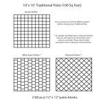
Proper use
1
Proper use
The PFAFF Docu-seam system is a supplementary quality assurance device, with which
safety-oriented seams can be observed and documented during the sewing process.
Process parameters are aquired online by a measurement device during stitch formation,
data are analyzed and documented.
The result ist a good/bad information about the sewn seam strength. On a seam file all
important process parameters are stored automatically.
Simultaneous to this operation a label is printed including these data in clear text and
barcode.
This label is sewn into the seam and makes retraceability possible for each seam.
Any use which is unauthorized by the manufacturer is regarded as contrary to
the instructions! The manufacturer does not accept responsibility for any
damage caused by improper use! Using the device according to the instructions
also involves compliance with all operating measures provided by the
manufacturer!
1-1
Installation
2
Installation
The following described installations may only be executed by adequately
specialist personnell! The danger and safety instructions on the machine itself
are to be followed!
2.01
System requirements
Hardware
● PC with Pentium processor, 800 MHz or higher, Disk drive
● 2 ISA slots, Standard hard disk, min. 64 MB RAM
● min. 14" color monitor, Microsoft-compatible mouse, CD-ROM drive
Software
● Microsoft WINDOWS 98®
● Control panel settings:
High Color 16 bit, Screen: 640 x 480
WINDOWS 98® is a registered trademark of MICROSOFT CORPORATION, USA
2.02
Installation of driver software NI-DAQ for WINDOWS
Attention: The NI-board... must be removed from the PC !!
In the delivered condition, the following installations have already been carried
out and must only be done for a new configuration.
After the PC is switched on, the Docu-seam program is started automatically.
Depending on the driver version the CD starts automatically or must be called
manually. The CD drive could be D:
Manual calling or CD starts automatically
● Start, Run, Browse, click on symbol My Computer
● Click on the CD drive
● Open NI-daq... (D:) with double click
● Directory of the CD is listed
● Open Setup.exe with double click ===> D:\setup.exe, OK
● Open Install NI-DAQ with double click
● NI-DAQ driver files, Next
● Select Destination Directory C:\NI-DAQ, Next
● Select Group is indicated, Next
● Ready to install, Next, file is installed
● Install, OK, Shut down PC, Restart
● Shut down PC
2-1
Installation
2.03
NI-DAQ Hardware Configuration
● Remove plug from the mains, plug in NI-board..., connect the flat wire
● Connect plug to the mains, Start the PC, My Computer, Control Panel, Add New
Hardware
● Add New Hardware Wizard, Next, Next, Search for your New Hardware, Yes, Next
● Next, Detection progress is running, Next, Hardwaretypes are listed
● Select Data Acquisition Devices, Next
● Models are listed: Select , Next
● Resourcetype and Settings are listed, Next
● Finish, Shut down PC
● Start WINDOWS
● My Computer, Control Panel, System, System Properties
Select Device Manager
● Open Data Acquisition Devices, Open NI-board...
● NI-board... Properties: Select Resources, if necessary change settings
and select new value
● I/0 range 0260-027 F, interrupt 05, DMA 03, OK, close
● Shut Down WINDOWS, Start PC
● Go to Start, Programs, National Instruments DAQ, NI-DAQ Configuration Utility
● Correct configuration is indicated, Next
● Configuration, OK
● File, Save, Exit
Handling conflict warnings
● If there is an interrupt conflict a new interrupt number must be set by a jumper
on the NI-board..., see User Manual.
● Similar to this set the DMA channel, see Lab-PC + User Manual page 2-6, and
the I/O range, see User Manual.
An indicated interrupt conflict leads to a failure during data aquisition and
indication, for example using the Monitor function.
Example
● Conflict: ECP-printer (LPT1), OK
● Conflict warning, Yes ===> Ressource setting
● Device conflict: DMA03 used by: ECP-printer (LPT1), OK
● Shut down WINDOWS, start WINDOWS, My Computer, Control Panel, System
● Device Manager, Conflicting device! Select ECP-printer
● Resources, manual configuration
● ECP-printer (LPT1) set on DMA1, no conflicting device
● OK, close
● Start, programs, National Instrument DAQ, NI-DAQ Configuration Utility
● Correct configuration is indicated, Next
● Configure, OK
● File, Save, Exit
2-2
Installation
2.04
Install Docu-Seam-Program from CD
● Start, Run, Browse, My Computer, select CD drive
● PFAFF directory is listed
● Open PFAFF, select Pfaffsetup.bat, Open, OK
● Program is installed on drive C:
● Start, Programs, WINDOWS Explorer
● Open directory PFAFF, select small screen
● Click on Icon DS11-... and drag and drop to desktop screen
● Close Explorer, Arrange Icons
● Install PFAFF Icon: click on with right mouse key, Pop up menu is opened
● Properties, Change Icon, Browse
● In directory PFAFF double click on PFAFF.ico, OK
● Apply, Close
● Start Docu-Seam-Program
● If taskbar appears on the screen do the following operation:
● Close the program using keys F1 and F12
● Start, Settings, select Taskbar & Start Menu,
● deactivate Always on top, activate Auto hide
● Apply, OK
● Restart the Docu-Seam-Program from WINDOWS
2.05
Linking the Docu-Seam-Program to Startup
● Click on Start with the right mouse key
● Click on Open, Programs, Startup
● Press Ctrl key and drag and drop the PFAFF Icon to Startup using the
left mouse key, Close, shut down PC, OK
● After Restart the Docu-Seam-Program is loaded and started automatically
The screen has to indicate the following 4 PFAFF icons:
DS-Config.exe, DS-Setup.exe, DS-Label-Copy.exe and DS11-...exe
2-3
Installation
2.06
Locking the WINDOWS function key
2.06.01
In WIN 98
● My Computer, Control Panel, System, Device Manager
● Open directory keyboard, Standard (101/102-key) or Microsoft Natural
Keyboard is indicated, OK
● Add New Hardware, Next, Next, No, the device is not listed, Next
● No, Select Hardware types, Next
● Hardware types: click on keyboard
● Models: Select Olivetti-keyboard (102-key), Next
● If conflict warning, Next, Finish
● Properties of, General, deactivate device user
● Click on Activate device, Restart PC, Yes
● The WINDOWS key is now locked in Docu-Seam-Program
2.06.02
In WIN 95
● My Computer, Control Panel, Keyboard, General
● Keyboard type is listed, Change, activate Show all devices
● Models: Select Olivetti-keyboard (102-key), OK, Close
● Restart your computer now, Yes
2.07
Shut Down Windows, automatically
This feature can be locked or unlocked in programm DS-Setup by opening
the Functions.
The meaning of the function slider Auto-Win-Exit is as follows:
Green:
After program stop by pressing F1 and F12 Windows will be Shut down
automatically.
Nevertheless if you want to jump to the Windows main screen (e.g.
configure DS-Setup) press F1 to stop the Docu program.
After pressing Alt Esc the start bar is visible. Clicking on Start, Programs,
Windows Explorer, folder PFAFF and DS-Setup, password 1 or 2 must be entered
to open the Functions and remove the slider Auto-WIN-Exit to Red.
After clicking on the key return you jump back to Setup level 2.
Clicking on the key Windows the program DS-Setup is closed and the Windows
Explorer is indicated. After closing the Explorer the Docu main screen is displayed
again. Now shut down Windows by pressing F1 and F12 to read the new setting
from Auto-WIN-Exit when the system is restarted.
Red:
This function is deactivated, means a program stop by pressing F1 and F12
switches to the Windows main screen.
2-4
Installation
2.08
Label Printers
After installation the printers must be selected as default printers!
Do not select WINDOWS-Printmanager!
The PC must be re-booted!
2.08.01
Gemini T Label printer
● Connect the printer as default printer to the parallel interface LPT 1 of the computer.
● Install the driver software under WINDOWS 98 as described in the printer manual
Setting the printer parameters
● Call up the Gemini symbol with a double mouse click.
The Gemini Control Panel opens.
● Printer: select Setup. Tharo Gemini opens.
● Set Unit to mm and type in 155.0 as Label Height (take care of your label size).
● Do not select Continuous Material!
● Select Landscape, X Fast Print.
● Label Printing Mode: Select Options..., Printer Mode opens.
● Select Batch Mode and set Presentation Position on 3.
● Select Thermal Transfer and set Heat Setting on 5, adapt if necessary.
● Set Printer Speed 50 mm/sec. and Label Offset on 0.0.
● Select OK, Tharo Gemini opens.
● Select field and deactivate Always on Top.
● Select field and close.
● Close Gemini.
Loading the barcode
● Call up the symbol Fonts in WINDOWS Control panel.
● Call up Add fonts
● Insert barcode disk and select disk drive ("A:").
● Double click Code 39.
A list of fonts is displayed.
● Double click Codedreineun Plain (True Type).
Font is displayed.
● Close function.
2-5
Installation
2.09
Network Installation (Instruction for self-installation)
2.09.01
Requirements
● Ethernet standard, IEE 802.3
● NE2000 compatible, WINDOWS 98, PCI-Bus
● Additional: BNC connector for coax cable, T-connector
● End resistor
● Definition:
● PC1 = Client = Docu-PC, access to resource (drive) of PC2
● PC2 = Server = External device, shares resource (drive) for PC 1
● Access to Docu-PC is not permitted!
2.09.02
Principle Configuration
Start of Network configuration
● Register card Configuration, Add, Client, Add
● Manufacturer: Microsoft, Network Clients: Client for Microsoft Networks, OK
Configuration of Network card
● Network, Add, Network card, Add
● Select network driver, for example select disk
● Diskdrive (default A:\) confirm with OK, select Model of network card,
for example select SN 2000 Ethernet Adapter, OK
Definition Network protocol
● Network, Add, Protocol, Add
● Manufacturer: Microsoft, Network protocol: IPX/SPX compatible protocol
Release resources (disk drive C) of PC2 (server)
● Network, Add, Service, Add
● Click File and Print Sharing for Microsoft Networks, OK
● Click Network, File and Print Sharing
● Mark both fields, OK
● Select Network, Access control with Share-level, OK
Select work groups and PC identification
● For PC1: Network, Identification, input of PC-name PC1
● Work group: Docu-System, Comment: ***, OK
● Same input for PC2, Restart the PC
Release drives and folders on PC2
● My Computer, select drive C:, open with right mouse click the
context menu, click Sharing
● Sharing As: Share Name C
● Access Type: Read-/Write Access, Apply, OK
2-6
Installation
Example:
● Open Network Neighbourhood after Network Installation, click PC2,
drive C, open with right mouse click the context menu.
● New, Folder, New Folder, Rename, PC1 input
● After clicking on folder PC1 the complete address is displayed in the
task bar: \\PC2\C\PC1.
● Configure in PC 1 setup: open DS-Setup, password 1 or 2 input.
● In Setup level 2 input of path for seam files: \\PC2\C\PC1, then return
to WINDOWS.
● If both PCs are connected to a network, seam files are only saved in PC2.
● If PC2 cannot receive data, a short warning is displayed on the screen,
data are saved automatically on PC1 (Docu-PC) in path C:\PFAFF\Seamfile.
● If no path for seam files was created in setup level 2, seam files are saved
automatically in path C:\PFAFF\Seamfile.
Depending on the configuration of functions in setup level 2 a network error
information can only be reset using password 1 or 2.
2.10
Configuration in Docu software and machine controller
2.10.01
Detection of the docu seam area
The docu seam area can be activated and deactivated by knee switch, fotocell or seam program (see chapter 3.10).
2.10.02
Language selection
Factory settings in program DS-Config.exe already select the language. Changing the
language here, you have to save the stitch-regulator position for PFAFF 3715-2/..
(see fig. 2-01):
● Doubleclick the icon DS-Config.exe to open this program.
● Move the slider with the mouse to the corresponding position.
● Click on the button Return. The selected language is saved.
If only the preselected language has to be changed, use the following procedure:
● Open file manager function.
● In "C:\PFAFF" open the file "poti-ref.txt" with a double click.
The contents of the file are displayed; the right-hand number group indicates the
language:
0.00 = German
3.00 = Spanish
1.00 = English
2.00 = French
● Enter the appropriate number, close the Editor function and start the docu-seam program.
2-7
Installation
Fig. 2 - 01
2.10.03
Teach in the stitch-regulator position (PFAFF 3715-2/...), see fig. 2 - 01
● Set both adjusting dials for the stitch length to "0".
● Turn the main shaft to take over the mechanical gear position.
● Enter the displayed stitch-regulator position in the field "zero position of stitch
regulator" into field "Input of zero position".
●
●
●
●
Press Return key.
Set both adjusting dials for the stitch length at the maximum position.
Turn the main shaft to take over the mechanical gear position.
Change the preset value of 320 in the field "Adaption of stitch-regulator" with the
mouse using the arrow symbols, so that the "End position of stitch-regulator" has the
exact value "100".
● Press the Return key.
● Clicking on the button Save data, the entered values are saved.
For teaching in only a new stitch length open the function Stitch Edit on the
docu screen, see chapter 3.09.05.
To deactivate this function set the Adaption of stitch regulator to "0".
2-8
Installation
2.10.04
Service information
-
-
The stitch-regulator potentiometer is installed with a resistance value of 1000 +/- 300
ohm (only PFAFF 3715-2/..) using a medium stitch length.
This is an electric voltage of 1.68V to 3.12V.
The actual value is the measured value displayed in the right lower corner of the screen
Monitoring stitch-regulator position. This indication too can be used to find the correct
assembly position.
-
If the synchroniser is dismantled, exchanged or adjusted, the starting position of the
synchroniser must be taught in again (only PFAFF 3715-2/..).
● In the operating field OC-TOP activate key 10, TE.
● Select parameter 700 Needle position 0 on the programming level B (mechanical
level).
● Push pedal forward once.
● Turn hand-wheel forward and position the tip of the needle exactly on the upper edge
of the needle plate.
● Push pedal forward once again.
● Deactivate key 10, TE.
● Start sewing procedure.
2-9
Installation
2.10.05
Parameter/Configuration-Settings
Enter settings on the control panel with display:
PFAFF 3715-1/..
Configuration
Meaning
9
Docu-Seam-monitoring: no
(Selection slider F2 may be positioned on Test seam, Save, Monitor or
Threadforce). In this cofiguration the machine can be used without DocuSeam-System.
10
Docu-Seam-monitoring: yes
(Selection slider F2 has to be positioned on Docu-Seam). If this condition is
not fullfilled, a Watchdog function will block the machine, a sewing operation
is not possible.
PFAFF 3715-2/..
Group Parameter Meaning
2
205
Max. speed
Adjustm. range Standard setting
100 - 2000
1500
300 - 6400
3200
100 - 10 000
3200
in Docu-Seam-Area
221
Max. speed
for sewing program
6
607
Max. speed
683
Docu-seam-monitoring yes / no
I = yes
I
(selection slider F2 must be
positioned on Docu seam)
If these conditions are not fullfilled, a
watchdog function is blocking the
machine, a sewing operation is not
possible.
II = no
(selection slider F2 must be
positioned on Test seam, Save,
Monitor or Thread force.
The machine can be used completely
independent on the Docu-Seam-System
9
991
WINDOWS-M, default
0 - 239
217
992
WINDOWS-K, default
0 - 239
85
Because of process security watch the parameter 683 and Configuration 9 or 10!
For information please see instruction manual of motor manufacturer.
2 - 10
Installation
2.10.06
Adjustment of thread force (thread tension)
The configuration must be executed in file Pfaff\DS-INI.txt.
The first character in this file defines the wanted version:
0 without electrical adjustment, mechanical version
1 electrical actuator for adjustment
2 electrical actuator for automatic controller (closed loop) adjustment
The exact function of setting/controlling the thread force is described in chapter
3.06 point 6.
2.11
Scanner Installation
● Looping the scanner via cable into keyboard
● Open WINDOWS Notepad
● Read installation codes from scanner manual:
- Restore Default
-
Wedge: IBM AT
Nationality: English
- Operating Test: 123456 (displayed in Notepad)
● Code selection for code 39 is read from scanner manual:
1. Read Enter configuration
2. Read Standard Code 39
3. Read Exit and Save configuration
2 - 11
Operation
3
Operation
3.01
How the Docu-Seam-System works
A sensor inserted in the needle thread course of the sewing machine determines the
actually occurring tensile forces on the needle thread (needle thread tension) at every stitch
during the sewing process.
The signals from the sensor are then evaluated in the PC via a signal input board and a
data acquisition board and are displayed on a monitor on a user interface running under
WINDOWS 98. The analysis of these signals provides information about the machine setting
and the quality of every individual completed stitch.
The seam area in which the system is to be activated (docu-seam area), is determined by
seam program, knee switch or photocell.
The docu-seam system compares the established thread tensile forces with the previouslyentered limit values and gives an evaluation of the seam on the monitor.
In the case of a good seam, a label can be issued, if necessary using
a printer, with the relevant signal to the PC interface.
Moreover, the docu-seam system activates a skip stitch detection function and reacts on
running out of bobbin thread.
Thread tension is no longer adjusted manually but it is preset by an electrical actuator
(setpoint). The closed loop controller always corrects the thread tension (feed back).
In addition, the docu-seam system offers the possibility of continuing to process the data
provided with standard spreadsheet programs.
A function for monitoring the number of stitches in the docu-seam area (calculation of the
average stitch length) can also be activated.
In conjunction with a PFAFF 3715-2/.. it is possible to monitor the stitch length setting dial
(determination of the stitch regulator position).
To increase process security 3 password levels are integrated which permit access on the
system and user funcitons.
Using a scanner, data comparison of the sewing process components is possible.
Sewing process data are saved under a significant identification number (printout also on
label) or can be used for a network connection.
Recommendation: in Docu-Seam-Area machine speed should not
exceed 2000 min-1.
3-1
Operation
3.02
Password Input, Setup levels
The Docu-Seam-System is protected by 3 setup levels.
To configure these levels you have to run the program DS-Setup, started from the
WINDOWS platform. Setup level 1 gives the information to make a password input (Fig. 3 - 01).
Fig. 3 - 01
Starting up the system for the first time, enter the factory preset password PFAFF.
Setup level 2 opens where additional inputs are possible (Fig. 3 - 02).
Fig. 3 - 02
3-2
Operation
Password 1
Clicking on the slider with the left mouse key it is moved up and the window
Password Level 1 opens (Fig. 3 - 03). Password PFAFF can be changed into a user
password. Using password 1 (highest priority) you get access to all safety areas and only a
person, responsible for the whole system, should get this password.
Fig. 3 - 03
Password 2
Opening the window for password 2 in setup level 2, a password list for level 2 (Fig. 3 - 04)
is displayed. Up to 5 substitutes of password 1 may be entered. Entering password 2
in setup level 1 there is no access in level 2 for the inputs of password 1 and
password 2. The other selections of setup level are released.
Fig. 3 - 04
3-3
Operation
Password 3
Opening the window for password 3 in setup level 2, a password list for level 3 (Fig. 3 - 05)
is displayed. The user may enter 20x6 characters to get access on the sewing process,
for example 2 characters for the operator, 2 characters for the plant-no., 2 characters
for the machine-no.
The Status LED field indicates 1 out of 20 passwords according to the actual entered
password 3. Now the screen indicates which password number (the hidden password 3) has
started the system.
Fig. 3 - 05
3.03
Path for seam files
Enter the path for saving seam files in Setup level 2 (Fig. 3-02). If no path is entered seam
files are saved automatically under C:\PFAFF\Seamfile (see also chapter 2.09.02
Configuration, principle).
3.04
Saving docu seam files on floppy disk too
If docu seam files have to be saved not only on hard disk or network but also on a floppy
disk, this function can be released or deactivated, see chapter 3.05.
Move the function slider to green, an input field in setup level 2 is indicated (Fig. 3-02) to
enter the path/folder for seam files also on floppy disk.
The path A:\Seamfile is preset automatically, may be changed if necessary.
The existing saving procedure on hard disk or network remains independent on this action.
If no floppy disk was inserted an indication appears on the screen: Please insert floppy
disk! Data were already saved on hard disk or network.
If a read only floppy disk was inserted an indication appears on the screen: Remove read
only on floppy disk! (e.g. set startup in BIOS on C).
In case of inserting a floppy disk without path/folder, the preselected path in setup program
is activated.
3-4
Operation
If memory capacity on the floppy disk is filled up to 1.38 MB, an indication appears on the
screen: Floppy disk full, insert new floppy disk! After inserting a new floppy disk the
saving process is executed.
3.05
Release functions
Move the slider Functions from red to green in setup level 2, (Fig. 3-02) and the screen
Functions:unlock/lock opens (Fig. 3-06).
Unlocking function means the slider on green, locking functions means slider on red.
-
-
High limit value, low limit value, Option (Fig. 3-06):
Green: Input is unlocked
Red:
Input is locked
F2 Selection, Scale, Label Form, Label/Scan, Stitch Edit
Green: WINDOWS can be opened
Red:
WINDOWS are locked
-
Label-Copy:
Green: Using the key combination Ctrl Shift F1, the label which is still in
Red:
-
memory can be printed. The label gets an imprint "Copy!"
Using the key combination, no Label-Copy is possible (see chapter Making
Label copies 3.09.10)
Stitch counter (incl. thread force diagram), Table, Min/Max,µ, s, Bargraph, Docu-seam-no.:
Green: Indications are visible
Red:
Indications are not visible
-
Unlock machine:
Green: After bad docu seam the sewing machine is not locked
Red:
-
SC reset daily:
Green: The seam counters (file SC.txt in path C:\PFAFF\Counter)
Red:
-
After bad docu seam the sewing machine is only unlocked by
entering password 1 or 2
are reset a 0:00 o’clock
The seam counters are reset to zero after reaching a total number
of docu seams of 9999.
Cross check no.:
Green: A cross check number (modulo 43) is appended to the barcode
Red:
No cross check number is calculated
-
-
NOK file:
Green: NOK files are saved, NOK is appended to the identification number
Red:
No NOK files are saved
Network/File:
Green: Deleting the error information and unlocking the machine is executed
automatically after about 5 seconds
Red:
Deleting the error information and unlocking the machine only by
entering password 1 or 2
3-5
Operation
-
Option:
Green: Input is unlocked
Red:
Input is locked
-
BT Change:
Green: No confirmation of bobbin change
Red:
-
-
Bobbin thread change must be confirmed by password 1 or 2, the machine is
unlocked
Setpoint, actual value:
Green: Input and indications are unlocked
Red:
Input and indications are locked
Scan-Exit:
Green: Execute Exit without password 1, 2
Red:
Execute Exit with password 1, 2
-
-
Auto-WIN-Exit:
Green: Shut down Windows automatically
Red:
No automatic Windows shut down
Label name, ext.:
Green: Reading the label name from external
Red:
Reading the label name not from external
-
Saving on floppy disk:
Green: Saving data on floppy disk too
Red:
No saving on floppy disk
Click on return, this configuration is save and left.
Fig. 3 - 06
3-6
Operation
3.06
Input Functions
The functions can be called up by clicking with the mouse or with the respective key.
14
13
12
1
11
10
9
Fig. 3 - 07
3
4
5
2
6
7
8
1 - Start ( F1 )
By calling this function, the program is started.
2 - Input ( Esc )
This function enables and/or blocks the input of limit values and the use of Option (Input
display red = input not active / Input display green = input active )
3 - High limit value ( F3 )
After calling this function when Input is activated, (see above), the high limit value for thread
force can be changed. After pressing <Return>, the newly-entered limit value is adopted and
saved. At the same time, Input is deactivated again (input display red).
4 - Low limit value ( F4 )
After calling this function when Input is active (see above, the low limit value for thread force
can be changed. After pressing <Return>, the newly-entered limit value is adopted and
saved. At the same time, Input is deactivated again (input display red).
5 - Option ( F5, F6, F7 )
After calling this function when Input is active (see Point 2 - Input), the number of
"permissible exceedings" can be entered, that is, the number of individual stitches, whose
thread force may lie outside the prescribed limit values.
This extension now allows the user to define the area of limit value exceedings
very exactly.
Example:
High Limit Value HLV=600 cN
Low Limit Value LLV=300 cN
Option F5= 2, F6= +50 cN, F7= -50 cN
3-7
Operation
If the High Limit Value is set to 600 cN (interrupted red line), and the Lower Limit Value is set
to 300 cN (interrupted red line), and 2 deviations are allowed, the new sewing results may be
within the new High Limit Value of 600 cN +50 cN = 650 cN (bold red line) and the new
Low Limit Value of 300 cN -50 cN = 250 cN (bold red line).
Each measured thread force, which leaves the exceeded tolerance range of 250 cN to 650
cN , immediately leads to a NOK seam.
This function leads to a more flexible system and can be adapted to more different
operations, with the focus on an exact definition of the sewing process itself to increase the
number of OK seams.
Blinking of the different signs leads to a better failure analysis in case of leaving the preset
tolerance range.
As long as the input at Option is still 0, no inputs at F6 or F7 are possible.
The entered values can be saved by pressing <Return>, the input is deactivated again
(indicator red).
6 - Controller ( F8 )
After calling this function two different inputs are available if the input is active.:
1. Electrical adjustment of thread force
To enter a value move selection slider F2 to Test seam. Enter a numeric value for the thread
force of 0 – 100% within the input field F8. Sewing tests have to prove whether the correct
thread force has been adjusted. Switching from Test seam to Docu seam the corresponding
percentage value is accepted, saved and is related to the actual sewing process (defined by
label name). This ensures a correct reproducibility of the sewing process.
Pressing the Return key the new value is accepted and saved, the input is deactivated again/
indicator red.
2. Automatic electrical adjustment of thread force (closed loop control)
Principle of controller loop:
This version shows a feedback control loop (Setpoint/Actual value comparator, sensor,
control valve, control device). Contrary to electrical adjustment the automatic controller loop
compensates the influence of external disturbance, means changes in thread force by
process effects are detected and compensated by automatic regulation. This ensures a
balanced distribution of the stitch related thread force values in the middle of the tolerance
range; drifting of thread force values is minimized and production of defective docu seams is
reduced.
In position Test seam various sewing tests must be made to achieve a correct seam quality.
The ascertained thread force value will be loaded to Docu seam by switching the slider to
this position and is related and saved to this actual sewing process (defined by label name).
This ensures a correct reproducibility of the sewing process.
Operation:
To enter a setpoint of thread force the selection slider F2 must be positioned on Test seam.
Enter the thread force setpoint in cN into field F8. At the end of the sewn test seam the
actual, representative value of thread force for this seam section is indicated in field Actual
3-8
Operation
value. In case of deviation between actual value and setpoint the thread force is regulated
and corrected automatically.
If setpoint and actual value are close together switch to Docu seam; the ascertained
stimulus control (electrical value for adjusting thread force) is downloaded. This value is
attached simultaneously to the actual sewing process (defined by label name).
Needing this sewing process again after a certain time (loading the corresponding label
name) the necessary thread force is readjusted automatically too, means the saved process
parameters are reloaded and reproducibility is ensured.
Remark:
"Heavy corrections" to the thread force are detected by the Docu-Seam-System, means a
stimulus control deviation of 40% related to the required and previous loaded value leads to
a warning information on the screen. The operator gets an information that there is any
reason for a heavy correction of the thread force. It is commendable to check thread guides,
eyelets, thread quality etc.
7 - Stop ( F1 )
By calling this function, the program is stopped (status = red).
After this, the WINDOWS platform can be reached by pressing the key F12.
For PFAFF 3715-1/.., using the machine panel, the configuration must be set to 9, if the
selection slider is not positioned on Docu seam, see chapter 2.10.05 Parameter/ Configuration settings
To sew a docu seam, configuration must be set to 10.
For PFAFF 3715-2/.., using the machine panel, parameter 683 must be set to II, if the
selection slider is not positioned on Docu seam, see chapter 2.10.05 Parameter/Configuration settings
To sew a docu seam, parameter 683 must be set to I.
8 - Selection ( F2 )
If the options display has been activated with F2, the functions can be selected by using the
mouse or the arrow keys on the keyboard.
Thread force ( <arrow keys> )
By using this function, the static thread force of both the needle and bobbin threads can
be measured, See Chapter 3.08 Measurement of static thread force.
Monitor ( <arrow keys> )
With this function, the flow of the dynamic thread force during the sewing process is
displayed on the thread force monitor. This function may be employed for the analysis of
signals and gives indications of the quality of stitch formation. With a corresponding
setting of the measuring ranges for the x- and y-axes, detailed and characteristic features
of the flow of the thread force can be recognized.
Save (<arrow keys>)
Switching from Monitor to Save, the dynamic thread force signal is saved on the screen.
3-9
Operation
Test seam (<arrow keys>)
After calling this function, a test seam = simulated docu seam can be sewn with the
slowest and fastest speeds planned for the docu-seam-area to check all settings.
There is no label printout and no identification number with seamfile.
The LED indicator Docu-Seam-Area shows Test.
Only in Test seam it is possible to enter values into panels F3-F8.
Docu seam ( <arrow keys> )
This function can be activated when all necessary values have been entered. The seam
supervision is active in the docu-seam function, as soon as the docu-seam area is
reached during the sewing process. There are no inputs F3 - F8 possible.
9 - Stitch edit
With this function it is possible to activate both, monitoring the number of stitches
(calculation of the average stitch length) and the stitch regulator position. See Chapter
3.09.04 Monitoring the number of stitches and 3.09.05 Monitoring the stitch-regulator
position.
10 - Label/Scan
By using this function, information concerning the selected label can be entered. See
Chapter 3.09.07 Label name, label selection.
In addition you can call up or execute the input for the scan function, see Chapter 3.09.13
Scanner function.
11 - Label Form.
With this function the label size and label printer can be selected.
12 - 14 Selection of measuring ranges (Scale)
The measuring ranges for thread force and time axes can be selected using this function. For
the thread force, full-scale values ranging between 100, 250, 500, 750, 1,000, 1,250 and
1,500 cN may be selected (see Pos. 13 on Fig. 3-06).
For the time axis, you have the full-scale values of 100, 200, 400, 600, 800, 1,000 or 1,200
ms at your disposal (see Pos. 14 on Fig. 3-07).
The full-scale values will be adopted both for display on the monitor and for the
bar graph display.
3 - 10
Operation
3.07
Display functions
The system offers a whole series of data which are displayed on the screen by the display
functions.
2
3
1
25
27
26
4
5
6
7
8
21- 24
9
10
11 12 13 14 15
16 17
18
20 19
28
29
30
Fig. 3 - 08
1 - Status display
This function displays the current status of the program
(red display = program not yet started / green display = program running).
3 - 11
Operation
2 - Thread force diagram
As well in position Test seam as in Docu seam (selectable with slider F2), the thread force
values of the executed stitches are indicated. These values represent the max. thread force
during stitch formation, means when the take up lever is in the upper death point. Each single stitch can be identified as a real numeric value in the thread force table 17. These values
are saved in the corresponding seam file on the PC (see chapter 3.12.04).
3 - Actual label
With this function the current label name = process name loaded is displayed.
All process parameters are downloaded when reading the label name (settings, label text....).
4 - Docu-seam area
This shows whether the machine is currently in the docu-seam area or not
(Green display = docu-seam ara / Red display = not in docu-seam area).
If F2 is on Test seam, Test is written into this field.
5 - Docu-seam
The result of the Docu-seam is displayed.
(Green display = docu-seam is in order/Red display = docu-seam is not in order).
Contemporary a numeric indication of the total number of executed docu seams is indicated
(indicator 11, Fig.3-8 indicates the OK and NOK docu seams).
6 - Skip stitches
From this display, you can recognize whether skip stitches have appeared in the docu-seam
area. (Green display = no skip stitch / Red display = skip stitch).
7 - Stitch length
From this display, you can recognize whether the calculated stitch length in the docu-seam
area is correct (preset seam length : counted stitches).
(Green display = stitch length in order / (Red display = stitch length not in order).
8 - Stitch regulator
This display shows whether the preset position of the stitch regulator has maintained .
(Green display = position in order / (Red display = position not in order).
9 - High limit value
In this panel, the adjusted value for the high limit value is displayed.
This display serves as an adjustment aid, to recognize during a test seam whether the
previously-set high limit value is being complied with.
(Green display = limit value not exceeded / Red display = limit value exceeded).
The high limit value is indicated as an interrupted red line in the thread force diagram point 2,
Fig. 3 - 08.
3 - 12
Operation
10 - Low limit value
In this panel, the adjusted value for the low limit value is displayed.
This display serves as an adjustment aid, to recognize during a test seam whether the
previously-set low limit value is being respected.
(Green display = not below limit value / Red display = below limit value).
The low limit value is indicated as an interrupted red line in the thread force diagram point 2,
Fig. 3 - 08.
11 - OK, NOK
OK:
NOK:
The number of good docu seams is indicated
The number of bad docu seams is indicated
12- Option (exceedings)
The number of preset and executed stitches within the docu seam area, falling outside the
limit values for thread force is indicated in this panel (extended tolerance range with F6 and
F7). The bold red lines in thread force diagram point 2, Fig. 3-08, show this extended
tolerance range. If only 1 stitch exceeds this extended tolerance range, an error warning is
indicated immediately.
13 - Input Esc
The mode in which the program is currently operating is displayed here by pressing key Esc.
(Red display = input not active / Green display = input active) Input keys F2 - F8 are unlocked.
14 - Stitches
The number of stitches in the docu- and test-seam area is displayed here.
15 – Closed loop controller
The preset Setpoint of thread force is indicated in this panel in cN.
This is the real gained, representative Actual value for the corresponding docu seam area.
If the system was configured as thread force controller without feedback, the indicator only
shows the preset percentage value of thread force.
If there is a mechanic thread force adjustment this panel remains empty. The necessary
configuration is described in chapter 2.10.06.
16 - Thread force table
All individual stitches sewn during a test seam or a docu-seam are displayed in this table
with the accompanying thread force. In this way, a seam analysis related to specific stitches
is made possible.
17 - Maximum thread force
The maximum thread force occurring during a test seam or a docu-seam is displayed here.
18 - Minimum thread force
The minimum thread force occurring during a test seam or a docu-seam is displayed here.
3 - 13
Operation
19 - µ
Out of the thread force values of table 16 the arithmetic average is calculated and indicated.
20 - s
Out of the thread force values of table 16 the standard deviation is calculated and indicated.
21 ... 24 Diagnosis-LEDs
To indicate controller signals and processes by using a simple method
several diagnosis-LEDs were placed in the lower right corner of the
Docu screen.
- WD... Watch Dog
- BT.....Bobbin Thread
blinks:
red:
Program runs in Docu seam
Alarm signal of bobbin thread monitor
- Cut....Cut
- Stop..Stop
red:
red:
Thread cutting
Machine stops, Error 9
25 - Bar display ( bar graph )
When the static thread force is measured, as well as during the test seam and the docuseam, the value of the thread force that has just been measured is displayed on the bar
display.
The division of the scale adjusts itself according to the newly-set full-scale value.
26...29 – Scale
If position Monitor is selected in panel Selection F2 scaling is possible.
-
Click on slider 26 or 27 for cN or ms and move upwards. A slider for setting the full scale
values of thread force 28 or time axis 29 appears on the thread force monitor.
-
Click on the needed scale value. The slider moves to the selected full scale value and
these values are accepted in the monitor and the bargraph.
-
Move the slider 26 and 27 down again.
30 - Monitor
Selecting the position Monitor in panel Selection F2, the dynamic thread force signal is
indicated. For a detailed signal analysis change the measurement ranges 26 - 29.
3 - 14
Operation
3.08
Measurement of static thread force
Besides the supervision of the docu-seam area, this system also offers the possibility of
measuring both the needle thread tension (force of the needle thread) and the bobbin thread
tension (force of the bobbin thread) without any additional device when the machine is
stationary.
In this way, you can have optimum, reproducible values for setting the machine which can
always be set precisely for every individual sewing process.
3.08.01
Measurement of static force on the needle thread
1
4
5
2
4
3
Fig. 3 - 09
● Thread the needle thread according to the machine class, taking into account that the
thread is passed through the thread force sensor, but not yet through the needle.
● Call up the Selection field with <F2>.
● If necessary, adjust the measuring range for the thread force (see Chapter 3.07 Display
functions, point 26, and 27, Fig. 3 - 08
● Select the function Thread Force using the <arrow keys> or the mouse.
A green text field 1 with instructions appears on the thread force monitor.
3 - 15
Operation
● After the signal, carry out at least 2 machine revolutions.
Machine stop at take-up lever T.D.C.
● Pull the needle thread evenly and slowly in the direction of the arrow until a red text field
2 appears on the thread force monitor.
The measured value can be read off the bar graph 3 and the display panel 4.
● If necessary, adjust the thread tension (knurled nut 5) and repeat the measuring
procedure after the signal, until the value for the thread force is correct.
The alternating procedure "Measure - read - adjust" takes place in a 6-second
rhythm, once the measuring function has been initialised by the revolution of
the machine.
3 - 16
Operation
3.08.02
Measurement of static force of the bobbin thread
1
2
4
4
3
5
Fig. 3 - 10
● Thread the bobbin thread through the thread force sensor and the take-up lever
(depending on the machine type).
● Call up the Selection field with <F2>.
● Set the measuring range for the thread force at 100 cN (see Chapter 3.07 Display
functions point 26 and 27, Fig. 3 - 08).
● Select the function Thread Force using the <arrow keys> or the mouse.
A green text field 1 with instructions appears on the thread force monitor.
● After the signal, carry out at least one machine revolution.
Machine stop at take-up lever T.D.C.
● Pull the bobbin thread evenly and slowly in the direction of the arrow until a red text field
2 appears on the thread force monitor.
The measured value can be read off the bar graph 3 and the display panel 4.
● If necessary, adjust the thread tension (screw 5) and repeat the measuring procedure
after the signal, until the value for the thread force is correct.
The alternating procedure "Measure - read - adjust" takes place in a 6-second
rhythm, once the measuring function has been initialised by the revolution of
the machine.
3 - 17
Operation
3.09
Test seam
The necessary requirements for the docu-seam area can be established by stitching off a
test seam. In the process, the system saves the thread force of the individual stitches and
displays the values on the thread force table 1 at the end of the test seam.
The maximum- or minimum-occurring thread forces are displayed in the Min/Max panel.
These thread forces serve as the basis for setting the limit values.
The original docu seam can be simulated here (parameter 683=I or configuration=10
remains), neither a label is printed nor the identification number with data file is created.
Test is written into the indicator LED Docu-Seam-Area. Only in Test seam inputs for panels
F3-F8 are possible.
In case of thread break in Test seam, a new stimulus control (setting) is
calculated which does not correspond to the correct preset values; therefore
enter manually a new setpoint.
3.09.01
Determining limit values
1
2
Fig. 3 - 11
First of all, the measuring ranges for the thread force and the time axes should
be selected appropriately and the static thread forces for the needle and bobbin
threads should be established or adjusted.
● Call up the Selection field with <F2>.
● Select the function Test-Seam using the <arrow keys> or the mouse.
● Stitch off the seam area, using the min. and max. speeds for the docu-seam area. During
the sewing procedure, the thread force occurring in every individual stitch is displayed on
the bar graph 1. Then the values are indicated in thread force table 2.
3 - 18
Operation
3.09.02
Setting limit values
After the maximum or minimum thread force by stitching off the test seam are established
(see Chapter 3.09.01 Determining limit values), the limit values for the thread force can be
entered.
3
2
1
Fig. 3 - 12
The limit values should be set at an appropriate and safe distance, according
to normal sewing practice, from the thread force values measured in the test
seam.
● Activate the input mode by pressing <Esc>. The input display 1 changes from red to
green. If key Caps Lock is activated, key <Esc> deactivated.
● Activate the input field for the high limit value with <F3>.
● Enter the high limit value.
● Activate the input field for the low limit value with <F4>.
● Enter the low limit value.
● Enter the options with <F5 - F7>.
● Confirm the input limit values by pressing <Return>.
The altered limit values are adopted and stored on the hard disk.
The input display 1 changes again from green to red.
In a similar fashion to the input of limit values, the input of "permissible
exceedings" can - if required - be carried out in the selection field 2 ("Option").
The occurrence of exceedings becomes more probable with a low tolerance
level in the limit values. An evaluation of the seam quality must determine
whether exceedings are permissible at all.
The actual number of exceedings occurring is displayed in field 3 (only active
within the docu-seam area).
3 - 19
Operation
3.09.03
Checking limit values
The sewing procedure (production) with the adjusted limit values can be simulated by
stitching off a further test seam.
1
2
3
Fig. 3 - 13
● Call up the Selection field with <F2>.
● Select the function Test seam using the <arrow keys> or the mouse.
● Stitch off the seam area.
During the sewing procedure, the thread force occurring in every individual stitch is
displayed on the bar graph 1.
When stitching off a test seam, the display elements 2 and 3 should not change
from green to red, unless a real error has occurred!
A check of the thread force values in the table is possible.
● Correct the limit values, if necessary.
3 - 20
Operation
3.09.04
Monitoring the number of stitches (calculated stitch length)
● Click on the slider in the panel Stitch Edit and move it to "Y" (for yes).
The input window Selection opens.
Fig. 3 - 14
● Click on the key Seam length/Stitch length, the panel Monitoring the number of
stitches opens.
Fig. 3 - 15
● The 4 input fields are activated by clicking on with the left mouse key or by pressing the
TAB-key.
These numerical values can also be increased or reduced by clicking on the
corresponding arrow fields.
● Enter the length of the docu-seam area (in millimeters) in the field "seam length".
3 - 21
Operation
● Enter the required number of stitches in the field "setpoint of number of stitches"
(Seam length : number of stitches = ideal stitch length). The stitch length resulting from
this calculation is stored in the seam file.
● Enter the allowable tolerance for the number of stitches in the docu-seam area in the
fields "+/- number of stitches". Example:
Seam length:
250 mm
Setpoint no. of stitches: 50
+/- number of stitches:
Result:
2
51 counted stitches in the docu-seam area, i.e. the docu-seam is in
order, because the tolerated number of stitches was not exceeded.
The average stitch length was therefore 4.9 mm (250 mm : 51). This is
stored automatically as the result in the seam file. The indication panel
for the stitch length remains green.
● To save these input values, click on the key "return with saving".
If the previous values are to be saved, click on the key "return without saving".
If the value "0" is entered for the seam length, the function "monitoring the
number of stitches" is deactivated.
3.09.05
Monitoring the stitch-regulator position
In the case of sewing machines with manual adjustment of the stitch length with an
adjusting dial, an integrated sensor monitors the stitch-regulator position for each stitch
length.
● The correct stitch length is determined by adjusting the adjusting dial or by making test
seams.
● Click on Stitch Edit and move to y (yes). Input panel selection opens. (Fig- 3 -14).
Fig. 3 - 16
3 - 22
Operation
● Click on the key Stitch regulator, the panel Monitoring the Stitch-regulator position
opens (Fig. 3- 16).
● The resulting correct position for the stitch-regulator is taken over as the setpoint by
clicking on the function "return with saving".
As long as the value of the actual position does not deviate from the setpoint by more
than +/-4 after sewing the docu-seam, the stitch-regulator position is considered to be in
order, i.e. the stitch-regulator indicator is green, and the setpoint and actual position are
stored automatically in the seam file.
To deactivate the function "Monitoring the stitch-regulator position",
the stitch-regulator adaption must be set to "0" in the Configuration program.
3 - 23
Operation
3.09.06
Label sizes, printer selection
● Click on the slider in the field "Label Form." and move it to "Y" (for yes).
The input window for the label sizes opens.
Fig. 3 - 17
● Open the menu by clicking on the arrow symbol.
● Press the left mouse key and position the mouse pointer in the desired field.
● Click on the key "return".
The window "Save As" opens.
Fig. 3 - 18
● Select your label as described in Chapter 3.09.07 Label name, label selection.
3 - 24
Operation
3.09.07
Label name, label selection
● Open the window "Save As". See Chapter 3.09.06 Label sizes, printer selection.
● Click on the desired label names, if these exist.
● Click on "Save".
Text and information about the selected label are displayed.
To create a new label:
● Enter the name of the label in the text field "file name".
● The cursor must blink in the input field.
The label name must have 8 characters, to which .txt is appended automatically.
● Click on "Save".
The window for text input opens.
Do not install new directories because program access is done automatically
to existing label directories.
3.09.08
Text input for label printer
All functions are explained with the example of the Gemini printer and with a label size of
110 x 45 mm.
Fig. 3 - 19
● Activate the input fields by clicking on with the mouse (the cursor appears in the
appropriate field) or by using the TAB-key.
3 - 25
Operation
After loading already existing label names all corresponding data appear which
can be handled here.
Input of clear text
Three rows with approximately 40 characters each can be entered.
● Activate the input field of the first row (the cursor blinks).
● Enter the text and press <Return>.
● Enter the text for the second row and press <Return>.
● Enter the text for the third row and press <Enter>.
Label output
Different output options can be selected.
● Click on the arrow symbol.
The menu opens.
● Click on desired field.
-
Text:
Only clear text is printed.
-
Text, Identification barcode:
Cleartext and Identification barcode is printed.
-
Text, Part code in ID-barcode:
Cleartext, 10 digits for user specific input and Identification barcode is printed.
To use the barcode function, the appropriate software (Option) must be
installed on the WINDOWS platform. See Chapter 2.08.01 Gemini T Label
Printer.
Number of labels
● The desired number of labels, from 0 - 9, can be selected by clicking on the arrow
symbol.
● If the setting "0" is selected, the information "no printer existing" appears.
● To end data input click on key return to save all adjustments.
Label selection
If there was a wrong label name selected by mistake, enter EXIT to execute a
new label selection.
3 - 26
Operation
3.09.09
Summary of the label sizes and printer selection
Gemini T, 45 mm x 155 mm
Label output:
Definition:
-
Clear text, 3 rows for customer data
Label name, seam number, date, time
Identification number
in addition with barcode
6 digits for customer input
4 digits for the year
3 digits for the day of the year
4 digits for Docu seam number
1 digit for cross check number
Number of labels:
0-9
Gemini T, 90 mm x 49 mm /01
Label output:
-
Clear text, 3 rows for customer data
Label name, seam number, date, time
Identification number
in addition with barcode
Definition:
-
2 digits for the year
3 digits for the day of the year
4 digits for Docu seam number
1 digit for cross check number
Number of labels:
0-9
Gemini T, 90 mm x 49 mm /02
The new version 90 mm x 49 mm/02 with a sewing space of 20 mm offers
a manual input field of 2 characters (numbers and capital letters) and
contents the following items:
-
3 rows for clear text
-
1 row for label name and seam number
1 row for date and time
-
1 row for identification-nr. in barcode (option cross check nr.)
1 row for identification-nr. in clear text
The Identification-nr. is defined as follows:
-
2 digits for manual input
2 digits for the year
-
3 digits for the day of the year
4 digits for the Docu seam number
-
1 digit for the cross check nr.(Option, only in Barcode visible)
Number of labels:
0-9
3 - 27
Operation
Gemini T, 90 mm x 35 mm
Label output:
- Clear text, 3 rows for customer data
- Label name, seam number, date, time
- Identification number
Definition:
- 2 digits for the year
- 3 digits for the day of the year
- 4 digits for Docu seam number
Number of labels: 0 - 9
Gemini T, 68 mm x 17 mm
Label output:
- Identification number
- in addition with barcode
Definition:
- 4 digits for customer input
- 2 digits for the year
- 3 digits for the day of the year
- 4 digits for Docu seam number
- 1 digit for cross check number
Number of labels:
0-9
For this label it is possible to enter 3 rows of clear text, which are not printed
but are saved in the seam file.
Gemini T, 110 mm x 45 mm
The transverse label printout offers a better print quality.
(Remark: Change printer driver settings: Label Height=45.0,
select Portrait)
The field Label output offers 3 selections:
Text:
3 rows for clear text, 1 row for label name and seam number
1 row for date and time
1 row for identification-number:
2 digits for the year
3 digits for the day of the year
4 digits for the Docu seam number
3 - 28
Operation
Text, Identification-Barcode:
3 rows for clear text, 1 row for label name and seam number
1 row for date and time
1 row for identification-nr. in barcode (option cross check nr.)
1 row for identification-nr. in clear text
The Identification-nr. is defined as follows:
6 digits for customer specific input, e.g. password 3
digits for the year
3 digits for the day of the year
4 digits for the Docu seam number
1 digit for the cross check nr. (option, only in barcode visible)
Text, Part code in ID-barcode:
3 rows for clear text, 1 row for label name and seam number
1 row for date and time
1 row for identification-nr. in barcode (option cross check nr.)
1 row for identification-nr. in clear text
The identification-nr. is defined as follows:
10 digits for customer specific input, e.g. part code
2 digits for the year
3 digits for the day of the year
4 digits for the Docu seam number
1 digit for the cross check nr. (option, only in barcode visible)
Number of labels:
0-9
Seiko, 28 mm x 89 mm
Label output:
- Clear text, 3 rows for customer data.
- Label name, seam number, date, time
- Identification number
Definition:
- 2 digits for the year
- 3 digits for the day of the year
- 4 digits for Docu seam number
Number of labels:
0-9
The cross check number (Modulo 43) is not appended to the text identification
number but is printed with the barcode, if the function was released in
setup level 2.
3 - 29
Operation
3.09.10
Making Label copies
To increase process security a separate program can be used if there is access
on Password 1 or 2.
The program DS-Label-Copy is started from the WINDOWS platform, a list is
displayed containing the saved seam files.
Clicking on the wanted seam file, the label is printed.
The screen displays the question: Another label copy?
No: Program exit, return to WINDOWS platform
Yes: List of seam files is displayed
If seam files are saved in other folders, they must be opened, too.
Labels of NOK seam files are not printed!
Label copies automatically get the additional printout "Copy!"
If the key combination Ctrl Shift F1 was unlocked in the function
configuration (setup level 2), the last, still saved label can be printed.
3.09.11
Loading a label name from external device
This function can be released or blocked in the setup program, see chapter 3.05. If this
function is used a superior master PC (network installation, Ethernet) can download a new
label name (includes all necessary sewing parameters) into the file Label-ID
(C:\Pfaff\Label-ID.txt). The new preselected label name has to exist already on the Docu PC.
A selection of a new label name can be executed only within the same label format. A new
label name is downloaded always after finishing a complete sewing process, means after
thread cutting.
3.09.12
Information for ordering the required materials
Gemini T Printer
Supplier:
Dalektron GmbH
Hainer Chaussee 55
63303 Dreieich
Telephone: 06103/86051, Telefax: 06103/88976
● Label 45 mm x 155 mm
In rolls, Tyvek permanent with heat transfer foil, Order-No. AA-300-050-SW
● Label 90 mm x 48,8 mm
In rolls, Tyvek permanent with heat transfer foil, Order-No. AA-300-090-SW
● Label 90 mm x 35,5 mm
In rolls, Tyvek permanent with heat transfer foil, Order-No. AA-300-090-SW
● Label 110 mm x 45 mm
In rolls, Tyvek Type D-281/0 with heat transfer foil, Order-No. AA-300-110-SW
3 - 30
Operation
Seiko Smart Label Printer 220
Supplier:
Inmac Micro Warehouse
Postfach 1280
65433 Flörsheim
Telephone: 0180/5237266, Telefax: 0180/5228229
● Label 28 mm x 89 mm, Inmac-No.: B-AC 7460
3.09.13
Scanner function
To recognize and check the sewing process components (threads, fabrics, etc.)
you can use this scanner function.
A comparison of the preset and acutal data is executed, the sewing process is only unlocked
if the data comparison was successful and scan data are saved then in the corresponding
seam file (OK or NOK).
For every sewing process the corresponding label must be selected and configured.
To open the scanner function for data input, click on the button Scan data of this
configuration screen. There are 10 rows available to enter up to 10 data.
Text
Enter clear text, description for example: Needle thread 1
Code
Only capital letters and numbers (no spaces) must be entered, for example: NT1.
Cycle
This is a setting which means, after how many docu seams a new scan operation must be
executed, for example: 15.
If the input is 1, the scan operation must be executed after each docu seam.
Clicking on the button return you leave the scanner function and the settings are saved
automatically together with the selected label name.
Fig. 3 - 20
3 - 31
Operation
● Calling existing label names (sewing process parameters are saved under
this name) the corresponding scan data settings are loaded automatically.
● If there is no cycle input, you are asked only once for the scan data after system
start.
● Starting the program you are asked for scanning your components.
In case of scanning new parts with new codes at the beginning of a new production
processs these scan data do not match with the loaded label of the old sewing process.
Now entering EXIT you can call the corresponding label selection.
● Before the sewing process you are asked to scan, this can be by-passed by entering
EXIT, if there are no pieces available at the work station; now a new label selection can
be executed.
● Thread cutting indicates the end of a sewing process. If a new order must be started
(new materials, new threads, etc.), the Docu-System needs these new data in connection
with the corresponding label (see chapter 3.09.06-3.09.08, 3.09.11).
If an already existing label is selected for another sewing process, the corresponding sewing parameters are loaded automatically.
After preparation for a new sewing process the next scan operation is asked
corresponding to the selected label with its corresponding scan data.
The handscanner can also be used to enter manual input like passwords and
codes using barcode 39.
3 - 32
Operation
3.10
Detecting the Docu-Seam-Area
The area of monitoring the seam can be activated by 3 different modes (see the following
table):
Knee switch
The operator has to press the knee switch to define the beginning and end of the docuseam-area.
Fotocell
Because of start and stop material flags the fotocell detects the docu-seam-area. It is
recommended to choose a specific size and shape for the material flags, an equal sided
triangle outside the seam with a hight of 15 mm.
The reflection area on the stitch plate must be lightly polished to secure a correct function. If
adaptions of the fotocell switching level are necessary, use the yellow adjustment screw at
the front side of the fotocell housing. Flashing of the yellow fotocell LED means the material
detection is instable.
Seam program, stitch counter
By entering seam programs, complete sewing processes or only seam sections can be
executed with the corresponding machine functions.
Detection of Docu-Seam-Area by means of:
Knee switch
Fotocell
Seam program
Stitch counter
PFAFF 3715-1/..
PFAFF 3715-2/..
Select in operation
mode Input the
Select in operation
mode Input the
Select in operation
mode Input the
symbol Knee switch
symbol Sensor
(fotocell)
Stitch counter
Parameter 994 = I
Parameter 994 = I
Parameter 995 = II
Parameter 995 = II
Activate operation
mode programmed
sewing by key T9
(P/M).
Parameter 994 = I
Parameter 995 = I
Do not connect the
Knee switch/fotocell
to the motor
controller.
Refer to example of seam programming chapter. 3.13
3 - 33
Operation
3.11
Sewing with the Docu-Seam-System
After the limit values for the thread force have been established, entered and tested,
production can be carried out monitored and controlled by system.
1
2
3
4
5
6
7
8 9
10
Fig. 3 - 21
● Call up the "Selection" field using <F2>.
● Select the function "docu-seam" using the <arrow keys> or the mouse.
If the system is restarted (beginning of operations), a program autostart takes
place after the devices are switched on. In this case, the default values from
the previous use are installed and the docu-seam function is activated.
See chapter 2.10 Configuration in Docusoftware and machine controller.
● Stitch off the seam.
As soon as the docu-seam area is reached, the seam monitor function is activated
(display 1 turns green). On leaving the docu-seam area (display 1 turns red again),
the seam results are displayed:
Docu seam is in order:
- The thread force diagram shows the sewing result, stitch by stitch
3 - 34
-
Display panels 2, 3, 4 and 5 are green
PC interface receives a signal (seam is in order)
-
Docu-seam number is increased by 1 and displayed in panel 2
The Docu-seam OK-indicator is increased by 1
-
Total number of stitches in the docu-seam-area is displayed in panel 7
Thread force table 8 contains all the individual stitches with the corresponding thread
-
force values
Maximum/minimum of occuring thread force is displayed in panel 9
Operation
-
The arithmetic average µ and the standard deviation s are displayed in panel 10
Seam file is stored on the hard disk and/or on floppy disk or linked to a network
-
The appropriate label is printed
Docu-seam is not in order:
- Display panel 2 and in case diplay panels 3, 4 or 5 are red
- PC interface receives no signal
- Docu-seam number is given
- The Docu-seam NOK-indicator in panel 6 is increased by 1
- Total number of stitches in the docu-seam-area is displayed in panel 7
- Thread force table 8 contains all the individual stitches with the corresponding thread
force values
- Maximum/minimum of occuring thread force is displayed in panel 9
- The arithmetic average µ and the standard deviation s are displayed in panel 10
- Seam file is stored with the extension NOK on hard disk and/or floppy disk or linked to a
network
- No label is printed
- The LED indicators are reset automatically after thread cut
Password after NOK-seam:
To increase process security after a NOK-seam you can finish the running sewing process
only after entering password 1 or 2. Therefore start program DS-Setup and open the
Functions to set the corresponding slider Unlock Machine to Red.
After a detected fault within the docu seam the machine is stopped now, (Error 9 or Stop
symbol on the machine display) the sewing material cannot be taken away because the
needle is in the material; an input field appears on the Docu screen for password 1 or 2. After entering the correct password the error indication appears in the machine display, the
machine remains locked. Quitting the error information on the machine display (PFAFF 37151/... key Enter, Pfaff 3715-2/... key S+), the machine is finally unlocked and the seam can be
finished.
3.12
Output functions of the Docu-Seam-System
The docu-seam system offers various possibilities for the evaluation and further processing
of stored information.
3.12.01
Thread force diagram
The complete Docu seam can be displayed in a diagram with this function including the
thread forces stitch by stitch. You get an immediate summary about the homogeneity of
your produced seam and you are able to check the distance to the limit values.
A sewing stop immediately indicates a thread force decrease while sewing over additional
plies of material the thread force increases. The more the sewing process is optimised to
constant thread forces, the less NOK seams are to be expected. This function is a tool to
make the sewing process itself and the sewing result visible.
If the selection slider F2 is positioned on Docu-Seam, this function is activated and scaling of
Y-axis (thread force in cN) is executed depending on preset limit values and scaling of the Xaxis is executed automatically depending on the number of sewn stitches.
This function can be released or locked in program DS-Setup, opening Functions and placing
the slider Table on the corresponding position (Green = visible, Red = not visible).
3 - 35
Operation
3.12.02
Monitor
After calling up the Monitor function, the dynamic thread force signal is displayed on the
thread force monitor.
In this way one has the possibility of a signal analysis of the dynamic thread force, which
gives indications of the quality of the stitch formation.
If the thread force analysis is used intensively in the "Monitor" function,
the signal form (the curve) can be stored on the screen by switching
from Monitor to Save during recording the signal (using arrow keys or mouse
click).
3.12.03
Thread force table
Every single stitch is listed in the thread force table too, together with the corresponding
thread force values (in Test and Docu-seam). Seams with a maximum of 4999 stitches per
docu seam can be processed. It is possible to scroll through the table by clicking the mouse
on the arrow keys at the side or by moving the slider.
3.12.04
Contents of the seam files
Seam files for good and bad docu seams are saved with the following parameters on hard
disk and/or floppy disk or network:
- Identification number
- contents of barcode
- cross check number
- part code
- password 3
- seam number
- date, time
- label name = process name
- label format
- clear text
- number of labels
- stitch length (calculated)
- high/low limit values
- seam length
- setpoint of no. of stitches
- +/- no. of stitches
- actual no. of stitches
- setpoint of stitch regulator position
- actual stitch regulator position
- option: input, +/-
- +/- tolerance
- actual option
- setpoint of thread force
- scan data
- actual thread force value
- statistical calculation: Min, Max
- arithmetic average
- thread force values for all stitches
- standard deviation
The thread force values out of the seam files can be processed further with standard
WINDOWS spreadsheet software, for example to prepare digrams or statistics.
3 - 36
Operation
3.12.05
Saving seam files
- The default setting is to save seam files on hard disk under
(configuration in setup level 2, chapter 3.02).
3.12.06
C:\PFAFF\seamfile
-
Data can be saved on floppy disk too (configuration in setup level 2, chapter 3.04).
Network saving (configuration chapter 2.09 and 3.02).
-
The stored seam files can be deleted or further processed in WINDOWS (path
C:\PFAFF\seamfile).
-
It is recommended that the user should archive the stored seam files at time intervals
determined by himself and then delete the archived seam files on the hard disk.
Seam file counter
Under C:\PFAFF\Counter\sc.txt 4 rows of information is saved:
1. Day of the year
2. Counter for all docu seams
3. Counter for good docu seams
4. Counter for bad docu seams
The counter values can be changed or reset in this file.
If new files get the name of already existing files, a WINDOWS error warning is
displayed on the screen.
3 - 37
Operation
3.13
Examples of seam programming
3.13.01
PFAFF 3715-1/..
The seam to be programmed should have
- 3 seam areas and
- be stored with the comment "docu"
- under program number 7.
● Call up the operation mode ENTER
Esc
Clear
1 2 3 4 5 6 7 8 9 0
Enter
Fig. 3 - 22
● Call up the function Programming (Number key 4)
Esc
PROGRAM NUMBER: 0
[ PERMISSIBLE:
Clear
1 - 99 ]
1 2 3 4 5 6 7 8 9 0
Enter
Fig. 3 - 23
7
● Enter programm number 7.
● Confirm input with Enter key.
(Display appears for entering comment).
Enter
Esc
COMMENT:
A B C D E F G H
I
1 2 3 4 5 6 7 8 9 0
Fig. 3 - 24
4
● Select letter D.
● Press right arrow key.
5 ● Select letter O.
● Complete comment using the above method.
3 - 38
Clear
J
Enter
Operation
Enter
● Confirm input with Enter key.
Esc
#1
NO. OF STITCHES 0
Clear
1 2 3 4 5 6 7 8 9 0
Enter
Fig. 3 - 24
● Program the first seam area (before the docu-seam)
The seam area should have
- stitch count (20 stitches)
- and a stitch length of 3.5 mm (for roller presser and wheel feed).
● Call up the function stitch length (Number key 4).
Esc
ROLLER PRESSER: 3,0 MM
FEED WHEEL: 3,0 MM
[ VALID: 0,8 MM - 5,0 MM
DIFF.: 1 MM ]
1 2 3 4 5 6 7 8 9 0
Clear
Enter
Fig. 3 - 25
The input is used for both stitch lengths. If different values have to be entered,
the roller presser and the wheel feed have to be selected with the use of the
arrow keys. Pay attention to the cursor.
3
5 ● Insert the desired stitch length.
Esc
ROLLER PRESSER: 3,5 MM
FEED WHEEL: 3,5 MM
[ VALID: 0,8 MM - 5,0 MM
DIFF.: 1 MM ]
1 2 3 4 5 6 7 8 9 0
Clear
Enter
Fig. 3 - 26
Enter
● Confirm stitch length input with Enter key.
Esc
#1
NO. OF STITCHES 0
Clear
1 2 3 4 5 6 7 8 9 0
Enter
Fig. 3 - 27
3 - 39
Operation
● Call up the function End of seam area (Number key 9).
Esc
#1
NO. OF STITCHES 0
Clear
1 2 3 4 5 6 7 8 9 0
Enter
Fig. 3 - 28
● The function stitch counter is already switched on (inverse). By operating the function
(Number key 1) the menu for the input of the number of stitches is opened.
Esc
NO. OF STITCHES: 0 STITCHES
Clear
[ PERMISSIBLE: 1 - 999 ]
1 2 3 4 5 6 7 8 9 0
Enter
Fig. 3 - 29
2 0
Enter
● Enter the desired number of stitches.
● Confirm input with Enter key.
Esc
#1
NO. OF STITCHES 20
Clear
1 2 3 4 5 6 7 8 9 0
Enter
Fig. 3 - 30
Enter
● Close the menu, end of seam area, with Enter key.
Esc
#1
NO. OF STITCHES 20
Clear
1 2 3 4 5 6 7 8 9 0
Enter
Fig. 3 - 31
● To program the second seam area, switch off the function End of program
Enter
3 - 40
(Number key 0).
● Press Enter key to teach in the first seam area.
Operation
● Program the second seam area (docu-seam area):
In the seam area
- the stitch length should be 5.0 mm
- the automatic stop function should carry out a stitch count (20 stitches)
- the speed should be reduced to 1500 min-1
- and the seam area should be recorded.
Esc
#2
NO. OF STITCHES 0
Clear
1 2 3 4 5 6 7 8 9 0
Enter
Fig. 3 - 32
● Call up the function stitch length.
Esc
ROLLER PRESSER: 3,5 MM
FEED WHEEL: 3,5 MM
[ VALID: 0,8 MM - 5,0 MM
DIFF.: 1 MM ]
1 2 3 4 5 6 7 8 9 0
Clear
Enter
Fig. 3 - 33
5 0
Enter
● Enter value for the stitch lengths.
● Confirm input with Enter key.
Esc
#2
NO. OF STITCHES 0
Clear
1 2 3 4 5 6 7 8 9 0
Enter
Fig. 3 - 34
● Call up the function for end of seam area (Number key 9).
Esc
#2
NO. OF STITCHES 0
Clear
1 2 3 4 5 6 7 8 9 0
Enter
Fig. 3 - 35
● Call up the menu for entering the number of stitches (Number key 1).
3 - 41
Operation
Esc
NO. OF STITCHES : 0 STITCHES
Clear
[ PERMISSIBLE: 1 - 999 ]
1 2 3 4 5 6 7 8 9 0
Enter
Fig. 3 - 36
2 0
Enter
● Enter desired number of stitches.
● Confirm number of stitches with Enter key.
● Switch on the function Docu-seam area.
● Switch on the function Stop.
Esc
#2
NO. OF STITCHES 20
Clear
1 2 3 4 5 6 7 8 9 0
Enter
Fig. 3 - 37
Enter
● Press Enter key to teach in the end of the seam area.
● Call up the function Speed.
1 5 0 0
3 - 42
● Enter desired speed.
Enter
● Confirm speed with Enter key.
Enter
● Press Enter key to teach in the second seam area.
The computer jumps to the input for the third seam area.
Operation
● Program the third seam area (docu-seam area):
The seam area should have
- a stitch count function (20 stitches),
- a stitch length of 2.5 mm (for roller presser and feed wheel)
- and a thread trimmer at the end of the seam area.
Esc
NO. OF STITCHES 0
#3
Clear
1 2 3 4 5 6 7 8 9 0
Enter
Fig. 3 - 38
● Call up the function stitch length (Number key 4).
2
5
Enter
● Enter value for the stitch lengths.
● Confirm input with Enter key.
● Call up the function for end of seam area (Number key 9).
● If the stitch counter function is not switched on, switch on the function (Number key 1).
● Select the stitch counter function once again to open up the menue for input.
2 0
Enter
● Enter number of stitches.
● Confirm number of stitches with Enter key.
● Switch on the Trim thread function (Number key 5).
Esc
#3
NO. OF STITCHES 20
Clear
1 2 3 4 5 6 7 8 9 0
Enter
Fig. 3 - 39
Enter
● Press Enter key to teach in the end of the seam area.
● Call up the End of program function.
3 - 43
Operation
Esc
NO. OF STITCHES 20
#3
Clear
1 2 3 4 5 6 7 8 9 0
Enter
Fig. 3 - 40
Enter
3.13.02
● Press Enter key to save the seam programm.
General information on seam programming on the PFAFF 3715-1/..
To achieve the best possible seam quality, please observe the following information.
● As the thread force values are dependent on the speed, it is useful to avoid changes in
speed within the docu-seam area. This enables a better tolerance for the limit values and
the number of seams classified as good increases.
● The speed should be reduced 5 stitches before the docu-seam area.
● If a docu-seam is classified as poor, the sewing procedure can be ended or interrupted by
switching over to manual sewing. To quit the error indication and to be able to sew
manually, the Number key 1 must be operated.
● If the sewing procedure is to be started at certain seam sections, the sewing positions
and program positions must coincide. If necessary the program must be set at the
required starting point manually.
● The needle must be positioned within the fabric at end of Docu.seam and stop within
Docu-seam, to prevent slippage or withdrawal of fabric.
● Additional symbols on the control panel:
Docu-seam-area activated
Bad (NOK) Docu-seam
Good (OK) Docu-seam
No Watchdog function, machine-PC communication is interrupted,
machine stops
3 - 44
Operation
3.13.03
PFAFF 3715-2/..
A
B
+
+
+
+
+
+
+
A
B
C
D
P
S
L
F1
I
0
0
I
D C
P
M
F2
F3
F4
T12
T13 T14
F5
T
E
Fig. 3 - 41
T9
Programming "before the docu-seam area"
● Switch on mains switch;
● Key T9 on;
PM-LED is on
● P +/- on 1;
● D +/- on 2;
Program start on program number 1
Switching program 1 to program 2
● A +/- on 2000;
● S +/- on 1;
Speed = 2000 min-1
Select seam section 1
● L +/- on 20;
● Press F1;
Enter 20 as number of stitches
LED on, i.e. forward to next program without a stop
● S +/- on 2;
● L +/- on 0;
Select seam section 2
Program 1 finished, move to program 2
● S +/- on 0;
Program combination, L +/- on 1
Programming "in the docu-seam area"
● P +/- on 2;
Program 2 selected
● D +/- on 3;
● A +/- on 1500;
Switching program 2 to program 3
Speed = 1500 min-1
● S +/- on 1;
● L +/- on 20;
Select seam section 1
Enter 20 as number of stitches
● Press F5;
● Press F1;
LED on, call up second level of the F-keys
LED on, docu-seam area activated
● Press F5;
● Press T12;
F5 blinks, F1 LED off, i.e. machine stops
LED on, lift foot
● S +/- on 2;
● L +/- on 0;
Select seam section 2
Program 2 finished, move to program 3
● S +/- on 0;
Program combination, L +/- on 1
3 - 45
Operation
Programming "after the docu-seam area"
● P +/- on 3;
Program 3 selected
● D +/- on 1;
● A +/- on 2000;
Return to program 1
Speed = 2000 min-1
● S +/- on 1;
● L +/- on 20;
Select seam section 1
Enter 20 as number of stitches
● Press T14;
● Press T13;
LED on, trim thread
LED on, lift foot, end of seam
● S +/- on 2;
● L +/- on 0;
Select seam section 2
Program 3 finished, move to program 1
● S +/- on 0;
Program combination, L +/- on 1
● Return to program start at No. 1 by pressing P-key
If seams with more than 255 stitches are to be programmed, the appropriate
number of seam sections have to be selected. For docu-seams with more than
255 stitches, each additional seam section must be entered with the key
sequence F5, F1, F5 (docu-seam activated).
3.13.04
General information on seam programming on the PFAFF 3715-2/..
To achieve the best possible seam quality, please observe the following information.
● As the thread force values are dependent on the speed, it is useful to avoid changes in
speed within the docu-seam area. This enables a better tolerance for the limit values and
the number of seams classified as good increases.
● The speed should be reduced 5 stitches before the docu-seam area.
● The machine stop after the docu-seam must be programmed. The machine then stops 3
stitches after the end of the docu-seam.
● Label printing takes place, if necessary the label can be sewn in.
● The next seam program can only take place after this procedure.
● In the case of manual sewing the docu-seam can be switched on and off by using the
knee switch.
● If a docu-seam is classified as poor, the sewing procedure can be ended or interrupted by
switching over to manual sewing. The key S+ on the operating panel has to be pressed
( to quit the error signal).
● If the sewing process is to be started at certain seam sections, the sewing positions and
program positions must coincide. If necessary the program must be set at the required
starting point manually.
● The needle must be positioned within the fabric at end of Docu-seam and stop within
Docu-seam, to prevent slippage or withdrawal of fabric.
● Additional symbols on the Quick operating panel:
On the LCD matrix following signs appear at the postion "/":
X
Docu-seam area activated
!
o
Error in docu-seam
No watchdog function, machine-PC communication is interrupted.
m
Manual sewing within a programmed seam,
activated by T4 (F4). Switching to the next programme takes place by
pressing the foot pedal fully backwards (Position 2-).
3 - 46
Extension
4
Extension
4.01
Coupling of Bobbin Thread Monitor with Docu-PC
Coupling the Bobbin Thread Monitor –926/06 with the Docu-PC leads to another monitoring
method of the sewing process included with the Docu-Seam-System. When the bobbin
thread monitor detects that the preselected amount of residual thread is reached (LED at
machine is blinking), in case of a correct preset of residual thread you can finish your running
sewing process without stopping the machine (Parameter 727 = II).
After thread cutting this bobbin thread alarm is evaluated and the sewing machine is
blocked (Error 9 on display, Parameter 679 = II). The Docu screen displays the question:
Bobbin Thread changed ?
After the bobbin thread was changed this operation must be confirmed by:
Pressing Key F10 or clicking on the Field F10 on the Docu screen with the mouse pointer.
After this confirmation Error 9 is deleted and the sewing machine is unlocked.
Parameters for PFAFF 3715-1/...
The option Bobbin Thread Monitor "6" can be activated/deactivated in chapter 11.08 in the
input menu at Switch Functions "1" of the sewing machine instruction manual.
To preset the still needed number of stitches after the 1. bobbin thread alarm, select
Counter "3" the option Delay, thread monitor "4" of the sewing machine instruction
manual.
Parameters for PFAFF 3715-2/...
679
I Error 92, restart of machine only by switching the main switch on/off
II Error 9, machine stops, Docu-PC resets Error 9, then the machine can start
again.
727
4.01.01
I Machine stops when residual amount of thread is reached.
II No machine stop when residual amount of thread is reached.
Unlocking with password 1 or 2
If the process Change Bobbin Thread must be secured even stronger, the machine release
can be made by entering password 1 or 2. Therefore start program DS-Setup and open the
Functions to set the slider BT Change to Red. After leaving the program DS-Setup and
starting the Docu-Seam-Program, an additional input field for password 1 or 2 appears on the
Docu screen. After entering the correct password the sewing machine is unlocked.
4-1
Extension
4.02
Exit function for label 110 x 45 mm
Using this integrated function you can react quick and flexible on changes in the production
process. If the label name = process name exists in a printed barcode, you can read this
name immediately by scanner without opening the label file.
Advantage:
Using this method, label data = process data are downloaded automatically after scanning
and also jumping back to the main program is executed at once.
This function too can be secured by password and switch Scan-Exit in program DS-Setup
and Functions.
Green:
Red:
4-2
Execute Exit without password 1 or 2
Execute Exit with password 1 or 2
Notes
PFAFF Industrie Maschinen GmbH
Postfach 3020
D-67653 Kaiserslautern
Königstr. 154
D-67655 Kaiserslautern
Telefon: (0631) 200-0
Telefax: (0631) 17202
E-Mail: [email protected]
Gedruckt in der BRD
Printed in Germany
Imprimé en R.F.A.
Impreso en la R.F.A.