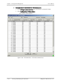
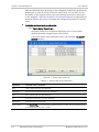
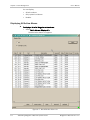
1
RADview-EMS/TDM Element Management System for TDM Applications Megaplex-2100/2104 © 1994–2008 RAD Data Communications Publication 07/08 Contents Chapter 1. Introduction 1.1 1.2 Overview.................................................................................................................... 1-1 Main System Features ............................................................................................. 1-1 Management Options ............................................................................................. 1-3 Manual Organization .................................................................................................. 1-3 Chapter 2. Installation and Setup 2.1 2.2 2.3 2.4 2.5 Preconfiguring Megaplex-2100/2104 for Management ................................................ 2-1 Preliminary Configuration Instructions ..................................................................... 2-1 Connecting Megaplex-2100/2104 to the Management Station .................................... 2-3 Direct Management Connection .............................................................................. 2-3 Management via LAN .............................................................................................. 2-3 Launching the RADview-EMS/TDM for Megaplex-2100/2104 ....................................... 2-4 Using the RADview Graphical User Interface ............................................................... 2-5 User Interface Principles ......................................................................................... 2-5 RADview Main Window ............................................................................................ 2-7 RADview Dialog Boxes ............................................................................................. 2-8 Viewing or Hiding Agent Mode ............................................................................ 2-9 Megaplex-2100/2104 Main Window ...................................................................... 2-10 Toolbar ................................................................................................................. 2-10 Menu Structure of Supervision Utility........................................................................ 2-11 Main Menu Structure............................................................................................. 2-11 Navigation Maps ................................................................................................... 2-12 Chapter 3. Configuration Management 3.1 3.2 3.3 3.4 Setting the System Parameters .................................................................................. 3-1 Viewing and Modifying System Logistics Information ............................................... 3-5 Setting the Date and Time ...................................................................................... 3-8 Polling the Agent .................................................................................................... 3-9 Resetting the Device ............................................................................................... 3-9 Displaying/Closing Agent Window ............................................................................ 3-9 Viewing and Modifying DB Operations ........................................................................ 3-9 Modifying the Configuration List ......................................................................... 3-9 Setting the Flip DB Agenda ............................................................................... 3-11 Setting Flip DB Net Events ................................................................................ 3-12 Setting Flip DB Decision Table .......................................................................... 3-16 Displaying Flip DB Net Events ........................................................................... 3-17 Updating (downloading) the Flip DB to the Megaplex ........................................ 3-19 Reading (Uploading) the Flip DB to the Edit Configuration................................. 3-19 Net Update ...................................................................................................... 3-19 Saving the Net Update Configuration ................................................................ 3-20 Saving the Flip DB ............................................................................................ 3-21 Setting the Net Update Delay ........................................................................... 3-21 Activating a Net Update ................................................................................... 3-21 Setting the Default Configuration ..................................................................... 3-22 Deleting an Agent Configuration ....................................................................... 3-23 Reading the Current Configuration of a Megaplex-2100/2104 ................................... 3-24 Updating the Megaplex-2100/2104 .......................................................................... 3-25 Megaplex-2100/2104 Ver. 12.6 i Table of Contents 3.5 3.6 3.7 3.8 3.9 3.10 3.11 3.12 3.13 ii User's Manual Viewing and Modifying Signaling Profile Parameters .................................................. 3-26 Configuring Legacy Data Profile ........................................................................ 3-27 Configuring R2 Data Profile .............................................................................. 3-28 Viewing and Modifying Redundancy Table Parameters .............................................. 3-33 Viewing and Modifying V5 Interface Parameters........................................................ 3-36 V5.1 Variants ................................................................................................... 3-36 Defining V5.1 Variant Data ............................................................................... 3-37 V5.2 Variants ................................................................................................... 3-41 Setting V5.2 Variants........................................................................................ 3-42 Adding V5.2 Variants ........................................................................................ 3-42 Setting C CH Parameters................................................................................... 3-43 Address Table .................................................................................................. 3-45 Viewing and Modifying Bundles ................................................................................ 3-49 Viewing the Bundle Connection Table .................................................................... 3-49 Customizing and Sorting the Columns ............................................................... 3-54 Showing and Hiding the Details of a Bundle ...................................................... 3-54 Adding an Entry in the Bundle Connection Table .................................................... 3-54 Changing an Entry in the Bundle Connection Table ................................................ 3-66 Removing an Entry in the Bundle Connection Table ............................................... 3-67 Viewing and Modifying Switching Table ..................................................................... 3-68 Viewing and Modifying T1/E1 Ring Management Parameters ..................................... 3-70 Adding an Entry in the Ring Table.......................................................................... 3-72 Changing an Entry in the Ring Table ...................................................................... 3-73 Removing an Entry in the Ring Table ..................................................................... 3-74 Viewing and Modifying the Managers List ................................................................. 3-75 Viewing and Modifying Card Operations .................................................................... 3-76 Zooming to Card View ........................................................................................... 3-76 Displaying Card Information .................................................................................. 3-77 Adding New Card .................................................................................................. 3-77 Updating Card Configuration ................................................................................. 3-79 Protecting ML-IP Card IP Address ........................................................................... 3-80 Removing Card Configuration ................................................................................ 3-81 Viewing and Modifying Port Operations .................................................................... 3-82 Setting Port Information ....................................................................................... 3-82 List of Supported Modules by Types ...................................................................... 3-82 Configuring ML-2E1 Module Parameters ................................................................ 3-85 ML-2E1 Port Information Parameters ................................................................ 3-85 ML-2E1 V5.1 Parameters .................................................................................. 3-88 ML-2E1 Redundancy Parameters ...................................................................... 3-90 T1/E1 Ring Management Parameters ................................................................ 3-91 Configuring ML-IP Module Parameters ................................................................... 3-91 ML-IP Port Information Parameters ................................................................... 3-91 ML-IP R2 TS Status Parameters ......................................................................... 3-94 ML-IP Bundle Parameters .................................................................................. 3-95 Configuring ML-20N Module Parameters................................................................ 3-99 ML-20N Port Information Parameters ............................................................... 3-99 ML-20N Status Parameters ............................................................................. 3-102 Displaying TS (Timeslot) Assignments .................................................................. 3-103 Split Timeslot ................................................................................................. 3-105 Configuring LS-12 Module Parameters ................................................................. 3-105 LS-12 Port Information Parameters ................................................................ 3-105 Configuring HS-12N Module Parameters .............................................................. 3-108 Configuring VC Module Parameters ...................................................................... 3-109 Configuring HS-ETH/SW Module Parameters ........................................................ 3-112 Megaplex-2100/2104 Ver. 12.6 User's Manual Table of Contents HS-ETH/SW Port Information Parameters ........................................................ 3-112 Configuring VFS Module Parameters .................................................................... 3-116 VFS Port Information Parameters .................................................................... 3-116 VFS Port TS (Timeslot) Connections ..................................................................... 3-122 Chapter 4. Security Management 4.1 4.2 Opening the Security Console..................................................................................... 4-1 Security Profiles ...................................................................................................... 4-1 Loading a Security Profile ................................................................................... 4-2 Adding a Profile.................................................................................................. 4-2 Changing Permissions ......................................................................................... 4-2 Editing Profiles ................................................................................................... 4-3 Removing Profile ................................................................................................ 4-3 User Security .......................................................................................................... 4-3 Adding a User .................................................................................................... 4-3 Editing a User..................................................................................................... 4-4 Changing a User’s Password ............................................................................... 4-4 Removing a User ................................................................................................ 4-4 RADview Basic Security Levels .................................................................................... 4-5 Administrator and Operator Levels .......................................................................... 4-5 Technician .............................................................................................................. 4-5 Monitor .................................................................................................................. 4-5 Chapter 5. Performance Management 5.1 5.2 5.3 5.4 Overview.................................................................................................................... 5-1 Starting Performance Monitoring ................................................................................ 5-1 System Level Operations ............................................................................................ 5-2 Port Level Statistics.................................................................................................... 5-3 Setting the Polling Interval ...................................................................................... 5-3 Displaying Current Data .......................................................................................... 5-4 Displaying a Current Data Table .......................................................................... 5-4 Displaying Intervals Data ......................................................................................... 5-7 Chapter 6. Fault Management 6.1 6.2 6.3 Displaying Sanity Check Results .................................................................................. 6-1 Handling Megaplex-2100/2104 System Alarms ........................................................... 6-3 Displaying All Active Alarms ..................................................................................... 6-4 Displaying System Level Alarms ............................................................................... 6-6 Displaying Active Bundle Alarms .............................................................................. 6-7 Clearing Alarms .................................................................................................. 6-8 Clearing All Alarms .............................................................................................. 6-8 Configuring Alarms.................................................................................................. 6-8 Setting Alarm Severity ........................................................................................ 6-8 Setting Alarm Attributes ................................................................................... 6-10 Sorting Alarm Attributes ....................................................................................... 6-13 Defining Scope of Alarm Reports........................................................................... 6-15 Read ACM Alarm Descriptions ........................................................................... 6-17 Displaying the History Log..................................................................................... 6-17 Displaying All Buffer Alarms .............................................................................. 6-17 Viewing New Buffer Alarms .............................................................................. 6-19 Managing Card Alarms .............................................................................................. 6-20 Displaying Alarms.................................................................................................. 6-20 Megaplex-2100/2104 Ver. 12.6 iii Table of Contents 6.4 6.5 iv User's Manual Clearing Card Alarms ............................................................................................. 6-23 Clearing All Alarms ................................................................................................ 6-23 Managing Port Alarms .............................................................................................. 6-24 Performing Diagnostic Tests.................................................................................. 6-24 BERT Counters ...................................................................................................... 6-27 Displaying Port Alarms .......................................................................................... 6-29 Clearing Port Alarms.............................................................................................. 6-30 Testing Megaplex-2100/2104 ................................................................................... 6-31 Megaplex-2100/2104 Ver. 12.6 Chapter 1 Introduction This User’s Manual describes the RADview management application for Megaplex-2100/2104. Note In this manual, the generic term Megaplex-2100/2104 is used when the information is applicable to all the equipment versions. The complete equipment designation is used when information is applicable to a specific version. 1.1 Overview The Megaplex-2100/2104 is a family of high-capacity user-configurable modular E1/T1 Integrating Access Devices with SNMP management. Megaplex-2100/2104 multiplexers provide an efficient and cost-effective method for integrating data, voice, fax, ISDN access, etc., for transmission over TDM networks, and are well adapted for use in corporate networks. Megaplex-2100/2104 equipment also supports the TDMoIP (TDM over IP) protocol and therefore can be integrated in corporate IP networks using IP basedbackbones. Main System Features Megaplex-2100/2104 systems are ideally suited to implementing custom system designs according to specific applications, and can be used to build cost-effective private corporate networks, as well as networks using public TDM carriers and IP transmission services. The Megaplex-2100/2104 systems are compatible with the Megaplex-2200 family of modular E1/T1 Integrating Access Nodes, and with the Megaplex-4100 next generation Multiservice nodes, also offered by RAD. When equipped with IP main link modules, Megaplex-2100/2104 systems are fully compatible with the IPmux family of TDMoIP gateways offered by RAD, and therefore permit the Megaplex equipment to become part of an integrated corporate IP network. Moreover, Megaplex-2100/2104 systems comply with the applicable standards, including support for ETSI V5.1 and V5.2 interfaces, and therefore are fully interoperable with TDM and TDMoIP equipment from other vendors and can be efficiently integrated in access networks. Megaplex-2100/2104 Ver. 12.6 Overview 1-1 Chapter 1 Introduction User’s Manual The Megaplex-2100/2104 systems are available in two chassis versions, which can be equipped with various types of main link and input/output (I/O) modules to provide the required user and system interfacing. Several power supply options are also available. The flexible modular construction and the advanced management capabilities of the Megaplex-2100/2104 family enable the using organization to easily configure individual systems for specific requirements and operating modes, and change rapidly system configurations. Moreover, the operating software can be remotely downloaded; therefore improvements and new features can be easily added across the whole network. The range of modules and options available for the Megaplex-2100/2104 family is continuously expanding. To minimize inventory and enhance system configuration flexibility, many of the modules available for the Megaplex-2100/2104 family can also be used by Megaplex-2100/2104 Hybrid. The I/O modules currently available include: • High-speed multichannel synchronous data I/O modules, operating at multiples of 56 kbps and 64 kbps. • Sub-multiplexer modules for low-speed synchronous and asynchronous data transmission. • Multichannel ISDN basic rate access modules, including support for data rate adaptation per ITU-T Rec. I.460. • Voice/fax sub-multiplexer modules with 2-wire and 4-wire interfaces and various signaling capabilities, which can directly connect to PBX and PSTN lines, as well as to fax and telephone sets. The voice modules are available in several versions, that support toll-quality PCM and ADPCM coding, or high-quality low-bit rate compression. • Ethernet LAN connectivity modules with internal Ethernet switch supporting port-based VLANs and VLAN tag-based switching or bridge, bridge/router, and IP router. • Multiport T1 (DS1) and E1 I/O and main link modules, which support applications such as fractional T1 and E1, direct connection to digital PBX, V5.1 and V5.2 trunk lines, and allow cascading of Megaplex-2100/2104 units. The current main link options support two families of interfaces: • Interfaces to TDM networks: T1 (1.544 Mbps), E1 (CEPT, 2.048 Mbps), as well as fractional T1 and fractional E1 data services. A wide range of electrical, optical and HDSL interfaces are available. • Interfaces to IP networks using 10/100BaseT or 100BaseFX Ethernet interfaces. • Interfaces to high-speed digital data services networks running at sub-E1 rates (n × 64 kbps in the range of 128 to 2048 kbps). Megaplex equipped with 8-port main link modules in conjunction with the 12-port high speed module features a traffic payload capacity of up to 248 DS0 timeslots. This capacity can be carried by 8 E1 links or 10 T1 links, or any equivalent combination of E1 and T1 links. The main link modules of version 11 and lower still support up to 124 DS0 timeslots (8 Mbps). This capacity can be carried by 4 E1 links or 5 T1 links, or any equivalent combination of T1 and E1 links. 1-2 Overview Megaplex-2100/2104 Ver. 12.6 User’s Manual Chapter 1 Introduction The number of main links that can be operated from the same chassis is not limited, and can be selected in accordance with customer’s requirements. For example, this permits a Megaplex-2100/2104 unit connected via a V5.2 interface to serve as a concentrator for the voice and ISDN traffic received via up to 22 E1 links. Main link utilization is user-programmable at the individual timeslot level, with full timeslot cross-connect capabilities. Timeslot utilization is user-programmable down to the bit level (minimum bandwidth allocation unit of two bits, i.e., 16 kbps). Megaplex-2100/2104 equipment can be powered by AC and DC power sources. To enhance system availability, Megaplex-2100/2104 supports main link redundancy, as well as common logic redundancy. When necessary, two power supply modules can be installed to provide redundancy. Management Options The Megaplex-2100/2104 equipment supports Telnet and SNMP management, both inband through the main links, and out-of-band through Ethernet or RS-232 supervisory ports. SNMP enables fully graphical, user-friendly management using the RADview network management stations offered by RAD, as well as management by other SNMP-based management systems. In addition, a supervision terminal that provides full configuration and management capabilities can be connected to the RS-232 supervisory ports, either directly or through modem links. 1.2 Manual Organization This manual is structured around FCAPS (Fault, Configuration, Accounting, Performance, Security), the ISO model of network management. This acronym describes the cornerstones of network management: Fault management Detects and correlates faults in network devices, isolates faults and initiates recovery actions Configuration management Provides the ability to track changes and configure, install and distribute software across the network for all network devices. Accounting management Provides the capability to collect and parse accounting data to generate network usage reports. Performance management Offers a continuous source from which to monitor network performance (QoS, CoS) and resource allocation. Security management Provides the ability to control the access to network resources. Megaplex-2100/2104 Ver. 12.6 Manual Organization 1-3 Chapter 1 Introduction User’s Manual Table 1-1. Mapping of FCAPS to the Applications and Sections in this Manual FCAPS Component Fault Management Function Path in Application Section in Manual Displaying sanity check results Fault See Displaying Sanity ´Sanity Check Errors Check Results Fault ´Alarms ´Display ´All… See Displaying All Fault ´Alarms ´Display ´System Level… See Displaying System Fault ´Alarms ´Display ´Bundles… See Displaying Active Clearing active alarms Fault ´Alarms ´Clear See Clearing Alarms Clearing all active card and port alarms Fault ´Alarms ´Clear All See Clearing All Fault ´Alarms ´Config. ´ Severity & ACM Relay… See Setting Alarm Fault ´Alarms ´Configuration ´Attributes… See Setting Alarm Fault ´Alarms ´ Configuration ´Reports… See Defining Scope of Initiate an update of the ACM Alarm Descriptions Fault ´Alarms ´ Configuration ´ Read ACM Alarm Descriptions … See Read ACM Alarm Displaying all Megaplex alarms Fault ´Alarms ´Display ´All… See Displaying All Active Alarms Displaying all Megaplex alarms Displaying system alarms Displaying active bundle alarms Setting alarm severity level Defining alarm attributes Defining scope of alarm reports 1-4 Manual Organization Active Alarms) Level Alarms) Bundle Alarms) Alarms Severity Attributes Alarm Reports Descriptions Megaplex-2100/2104 Ver. 12.6 User’s Manual FCAPS Component Chapter 1 Introduction Function Path in Application Section in Manual Displaying buffer alarms Fault ´History Log ´All… See Displaying All Fault ´History Log ´Ack See Viewing New Displaying new buffer alarms since last ACK Fault ´History Log ´Since Last Ack… See Viewing New Running diagnostic tests Diagnostics ´Bundle Connection Test… See Megaplex Level Diagnostics ´Test… See Running Sets the alarm buffer from this point on Running diagnostic tests (ports) Configuration Management Buffer Alarms Buffer Alarms Buffer Alarms Diagnostic Operations Diagnostic Tests Viewing BERT Counters (ports) Diagnostics ´Bert Counters… See BERT Counters Printing BERT Log (ports) Diagnostics ´Print Bert Log… See BERT Counters Setting Mux timing information Configuration ´Info ´Mux Info… See Performing Megaplex Timing Configuration Displaying system information Configuration ´Info ´System Info… See Displaying System Configuration ´DB Operations ´Select Config… See Modifying the Setting flip DB agenda Configuration ´DB Operations ´Flip DB ´Agenda… See Setting the Flip DB Agenda Setting flip DB net events Configuration ´DB Operations ´Flip DB ´Net Events… See Setting Flip DB Net Events Defining events that cause RADview to flip to specific configuration Configuration ´DB Operations ´Flip DB ´Decision Table… See Setting Flip DB Decision Table Setting voice level offset Setting Megaplex configuration Megaplex-2100/2104 Ver. 12.6 Information Configuration List Manual Organization 1-5 Chapter 1 Introduction FCAPS Component 1-6 User’s Manual Function Path in Application Section in Manual Saving (downloading) edit flip configuration parameters to agent Configuration ´DB Operations ´Flip DB ´Update… See Updating (downloading) the Flip DB to the Megaplex Reading (uploading) flip parameters from Configuration agent to edit flip configuration ´DB Operations ´Flip DB ´Read… See Reading Saving current edit configuration to all Muxes in net Configuration ´DB Operations ´Net Update ´Save Config… See Saving the Net Saving current flip configuration to all Muxes in net Configuration ´DB Operations ´Net Update ´Save Flip DB See Saving the Flip DB Transferring current agent configuration to edit configuration Configuration ´Read… See Reading the Transferring edit configuration to agent configuration Configuration ´Update… See Updating the Configuration to the Agent Configuring system signaling profiles Configuration ´ Signaling Profile… See Setting Signaling Profile Parameters Setting redundancy parameters Configuration ´Redundancy Table… See Setting Redundancy Table Parameters Setting V5.1 Variants Configuration ´V5 Interface ´V5.1 Variants… See V5.1 Variants Setting V5.2 Variant General Configuration Configuration ´V5 Interface ´V5.2 ´General… See V5.2 Variants Setting V5.2 Variants Configuration ´V5 Interface ´V5.2 ´Variants… See Setting V5.2 Variants Configuring Bundle Parameters Configuration ´Bundle Connection Table… See Configuring Bundles Configuring the Switching Table Configuration ´Switching Table… See Configuring Switching Table Manual Organization (Uploading) the Flip DB to the Edit Configuration Update Configuration Agent Configuration Megaplex-2100/2104 Ver. 12.6 User’s Manual FCAPS Component Performance Management Chapter 1 Introduction Function Path in Application Section in Manual Configuring T1/E1 Ring Configuration ´T1/E1 Ring Table… See T1/E1 Ring Management Polling the agent Configuration ´Poll Agent See Polling the Agent Viewing statistics Statistics ´Bundle Connection Statistics… See System Level Setting polling interval Statistics ´Polling Interval… See Setting the Polling Interval Displaying current data statistics in table or graph Statistics ´Current Data… See Displaying Displaying intervals data statistics in table or graph Statistics ´Intervals Data… See Displaying Intervals Data Function Path in Application Section in Manual To start the Security Console EMS Admin Console ´Security Services See Opening the Loading a Security Profile Profile ´Load... See Loading a Security Profile Adding a Profile Profile ´Add... See Adding a Profile Editing Profiles Profile ´Edit... See Editing Profiles Removing Profile Profile ´Remove See Removing Profile User Security User See User Security Adding a User User ´Add... See Adding a User Editing a User User ´Edit... See Editing a User Changing a User’s Password User ´Edit... See Changing a User’s Password Removing a User User ´Remove See Removing a User Operations Current Data FCAPS Component Security Management Megaplex-2100/2104 Ver. 12.6 Security Console Manual Organization 1-7 Chapter 1 Introduction 1-8 Manual Organization User’s Manual Megaplex-2100/2104 Ver. 12.6 Chapter 2 Installation and Setup This chapter describes how to prepare the Megaplex-2100/2104 for remote management. The chapter includes the following sections: • Preconfiguring Megaplex-2100/2104 for management • Connecting Megaplex-2100/2104 to the RADview network management station (NMS) • Launching the RADview-EMS/TDM for Megaplex-2100/2104 • Using the RADview graphical user interface (GUI). 2.1 Preconfiguring Megaplex-2100/2104 for Management Megaplex-2100/2104 can be managed by any SNMP-based network management station, provided IP communication is possible with the management station. To manage the Megaplex-2100/2104 from a remote NMS, it is necessary to preconfigure the basic parameters using a supervision terminal connected to the Megaplex-2100/2104 CONTROL port. You can find detailed instructions on preconfiguring the Megaplex-2100/2104 for management in the Megaplex-2100/2104 Installation and Operation Manual. Preliminary Configuration Instructions In Section 4.4 of the Megaplex-2100/2104 Installation and Operation Manual you will find the supervision terminal log-in procedure, and the preliminary configuration instructions to be performed by means of the supervision terminal. Preliminary hardware configuration for the Megaplex-2100/2104 is performed using a Terminal Emulation program. When selecting parameters, click the <F> and <B> keys to move forward and backwards among the possible values for the selected parameter. Click <Enter> to make a selection and the spacebar to move on to the next parameter. ³ To initiate terminal operation with the Megaplex-2100/2104: 1. With the PS and CL cards in place, switch unit to ON. 2. On the active CL card, set the DIP/pin adjacent to the alarm LED to ON. Megaplex-2100/2104 Ver. 12.6 Preconfiguring Megaplex-2100/2104 for Management 2-1 Chapter 2 Installation and Setup User’s Manual 3. Double-click the Terminal's icon. 4. Select the correct COM port, and then from the Setting menu, select Communication. 5. Enter the following Communication Parameters, and then click <OK>: − Baud Rate: 9600 − Data Bits: 8 − Stop Bits: 1 − Parity: None − Flow Control: None Note At the beginning of terminal emulation, and after specified time-out periods, you will be prompted to type the password. The default password is ENTER. 6. From the Setting menu, select Modem Communications. 7. Change the setting in the Modem Defaults field to None and then click <OK>. 8. Enter the terminal definition in the field provided. For example, for VT-100, type DEF TERM VT-100, and then click <Enter>. ³ To define agent parameters: 1. Type def agent and click <Enter>. 2. Enter appropriate values for the following in the fields provided: ³ − MUX name: Megaplex-2100 − IP address: (999.999.999.999) − Net Id: 1 to 255 − SNMP Read Community: (up to 8 characters) public − SNMP Write Community: (up to 8 characters) private (for WAN) − SNMP Trap Community: (up to 8 characters) Public To define serial port parameters: 1. Type def sp, then click <Enter>. The default parameters will be displayed. 2. Set the baud rate, data bits, and stop bits to correspond to the SLIP, by entering values that correspond to the Communication Parameters entered for the Megaplex. 3. Set the auxiliary device to SLIP NMS, and then click <Enter>. 2-2 Preconfiguring Megaplex-2100/2104 for Management Megaplex-2100/2104 Ver. 12.6 User’s Manual Chapter 2 Installation and Setup ³ To update the database: • ³ Type db upd and a number between 1 and 10, and then click <Enter>. To complete the configuration: 1. Type bye and click <Enter>. The Terminal configuration window closes. 2. Close the Terminal Screen's icon. 3. On the active CL card, set the DIP/pin adjacent to the alarm LED to OFF. 2.2 Connecting Megaplex-2100/2104 to the Management Station The RADview management station may be connected to Megaplex units in one of the following setups: • Direct management-to-TDM link running on Single Line Internet Protocol (SLIP) • Connection from management station in a LAN through an MBE to a TDM unit. Direct Management Connection In this application, the management station is connected directly to a Megaplex unit. If more than one device is installed on this network, the device directly connected to management is the local unit. Any other devices are remote. This application requires installation of SLIP. It is the customer's responsibility to acquire a SLIP communication program and to install it according to the manufacturer's instructions. RADview supports both public domain SLIP and vendor SLIP. Figure 2-1 shows a sample direct management application. SLIP RADview Management Station Megaplex Figure 2-1. Direct Management Application Management via LAN In this application, the management station is connected to the device through an Ethernet LAN and an MBE (Ethernet Elementary Bridge). If the MBE and the device are located in the same subnet, the system will operate immediately upon hardware connection with no need for further software configuration. Megaplex-2100/2104 Ver. 12.6 Connecting Megaplex-2100/2104 to the Management Station 2-3 Chapter 2 Installation and Setup User’s Manual Figure 2-2 and Figure 2-3 show a sample management via LAN application. Ethernet Main Link E1/T1 SLIP Megaplex MBE Megaplex RADview Management Station Figure 2-2. Megaplex Management via LAN Ethernet Local Remote E1 DXC DXC E1 RADview Management Station Megaplex Megaplex Figure 2-3. Megaplex or DXC Management via LAN 2.3 Note Launching the RADview-EMS/TDM for Megaplex-2100/2104 For detailed instructions, refer to the RADview NMS User’s Manual. The RADview EMS Server application, which manages the EMS system, is automatically started when the RADview station is up. However, after rebooting the station, wait three to four minutes before you start to work with the EMS application. The EMS functions are activated by means of the LaunchDesk toolbar. If necessary, use the Windows Explorer to start the LaunchDesk toolbar: select Programs > Network Manager > RADview EMS > LaunchDesk. After the RADview station is up and running, you can start the RADview agent application for any manageable RAD device. The desired device can be selected from the EMS Network Elements Tree or from the SNMP Management Console map (a typical map is shown below). 2-4 Launching the RADview-EMS/TDM for Megaplex-2100/2104 Megaplex-2100/2104 Ver. 12.6 User’s Manual Chapter 2 Installation and Setup Figure 2-4. SNMP Management Console Screen, Typical Managed Subnet Map To open the agent Zoom window, double-click the desired icon in the SNMPc map or in the EMS Network Elements Tree, or right-click on the item in the EMS Network Elements Tree and select Zoom on the object menu. Refer to Section 2.4 for a description of the agent Zoom window. 2.4 Using the RADview Graphical User Interface User Interface Principles RADview has a graphical user interface (GUI) that lets you perform rapidly and efficiently all the tasks needed to configure, control, monitor and troubleshoot any Megaplex-2100/2104 equipment version from a remote location, yet conveys the impression that you are near the equipment looking at its panel. It also enables preparing completely new sets of parameters (“configurations”) or preparing a change in the current operating mode (new configuration) without disrupting the services performed by the Megaplex-2100/2104 unit until everything is ready. For this purpose, the RADview-EMS/TDM Megaplex-2100/2104 main window uses a graphical display that shows a life-like representation of a true Megaplex2100/2104 unit, and the window is divided into two sections: Megaplex-2100/2104 Ver. 12.6 Using the RADview Graphical User Interface 2-5 Chapter 2 Installation and Setup User’s Manual • The upper section, called the Edit window, is used to make changes or prepare new configurations. Making changes in this window is called working in the Edit mode. • The lower section, called the Agent window, displays the current state of a selected Megaplex-2100/2104 unit. Any operation made in this window is called working in the Agent mode. At any time, only one of these two sections are in focus. The main difference between the two modes is as follows: • To work in the Agent mode, the RADview station must be able to manage that unit. The prerequisites for managing are: Be able to communicate full duplex with that unit (you cannot move the focus to the Agent window if communication with the unit is not possible). Be allowed (authorized) to make the desired changes, a function taken care of by the RADview security functions and by appropriate configuration of the unit to be managed (as a minimum, such configuration requires preliminary configuration by means of a supervision terminal, as explained in Chapter 2). In the Agent mode, any command sent to a managed unit is immediately executed. Therefore, you must use the Agent mode to monitor the unit, retrieve performance statistics, send commands such as Reset (restart) the unit, and perform tests. Note that the managed unit is polled only when the Agent window is in focus. If the focus is moved to the Edit mode, the Agent window continues displaying the last known state, until the managed unit is polled again. • Note In contrast, when working in the Edit mode, you prepare sets of parameters that are stored in the RADview station. Therefore, you can prepare and store new configurations for any unit, even if the RADview station cannot communicate with that unit (off-line configuration). RADview-EMS/TDM is an element manager: it lets you manage a selected network element that is selected, using the general RADview NMS services, on a subnet map. The Agent window is empty if the station could not establish communication with the selected unit, to establish a baseline status for the Edit window. In this case, the NMS displays a dialog box in which you can fill in the main equipment characteristics: • Network link type, number of links, and the APS option. • Type and number of PDH ports, or presence of a sub link. • Type and number of Ethernet ports. • Number of VCGs supported. This information is used to characterize the new device. The information is updated after management communication with the device is established. 2-6 Using the RADview Graphical User Interface Megaplex-2100/2104 Ver. 12.6 User’s Manual Chapter 2 Installation and Setup To bridge between the two modes, RADview provides the following commands, both used in the Edit mode: • Read command: upload the current configuration of the desired unit to the RADview station, to be displayed in the Edit window. You can then start configuring the unit from its true current configuration. • Update command: download the configuration from the RADview station to the managed unit. When you update, the managed unit checks the received configuration (sanity check) to detect possible errors and conflicts, and if it accepts it – saves the new configuration in its non-volatile memory and starts using it. Other system-level commands you need to know about: • Poll: retrieve status from the managed unit. The retrieved status is used to update the Agent window. This command is available in both the Agent mode and Edit mode. • Reset HW: resets the managed unit (warm restart). RADview Main Window The RADview main window has two sections: one for the Edit mode and the other for the Agent mode. The Agent mode represents the true state of the managed device, whenever management communication is possible. All the graphical conventions in the RADview agent application match those in the main RADview (NMS) application. A few of the conventions are presented below. 1. Each section displays the Megaplex-2100/2104 front panel, including all of its ports, as determined by means of Megaplex-2100/2104 configuration entered by you, or discovered in the course of management communication with the unit. You can select configurable items in each section by clicking on the item (for example, port symbols). You cannot select non-configurable items. 2. To select the whole unit (system level), click somewhere within the window on any area not dedicated to another selectable item. 3. A light blue border marks the selected item (the item in focus): the whole device or a specific port. For connectors which represent multiple ports (channels), for example, the PDH ports, clicking within the connector area under the number of a port displays a blue selection box, which indicates that the port is selected. 4. In the Agent window, the magenta color is used to indicate that an item (fan, port, PS module) failed, is not present, or cannot be managed. 5. The current mode is displayed at the top-left of the main window as Edit or Agent. In other dialog boxes, the mode is indicated by E.# or A.# at the topleft of the dialog box, where # varies in accordance with the number of open boxes. 6. The menus and the available menu options vary, depending on the mode (Edit or Agent) and the item selected in the main window (the device, or one of its ports). Certain actions can only be performed in one of the modes. For example, setting time and date can only be performed in the Agent Mode. Megaplex-2100/2104 Ver. 12.6 Using the RADview Graphical User Interface 2-7 Chapter 2 Installation and Setup User’s Manual Sometimes, congestion in the network handling the management traffic means that significant delays occurs during polling, transfer of large data tables, etc. In such cases, the operator is notified that the process continues. In some cases, a progress bar cannot be used, and a message is displayed in the status bar at the bottom of the screen, as follows: Working... Displayed from the moment when a request is sent to the Megaplex-2100/2104, until data is received or a certain time expires (a few seconds). Waiting... Displayed while the RADview station waits more than a few seconds for the Megaplex-2100/2104 response, but less than the time-out time. Interrupted When all attempts to communicate with the Megaplex2100/2104 failed (time-out), or when the Megaplex2100/2104 response was an SNMP error. Ready Displayed after the process has been successfully completed. 7. Pop-up menus are used to expedite operations: when the cursor is on a selectable object, and the secondary (usually – the right-hand mouse button) is pressed, a pop-up menu will be displayed. This pop-up menu depends on the selected object. The pop-up menu start with the top level menu appearing in the regular menu bar (e.g. Configuration, Fault, etc.). RADview Dialog Boxes Dialog boxes are used both to configure parameters and to display status information, and therefore can include a wide range of elements. The most common types of elements are described below. Since RADview-EMS/TDM for Megaplex-2100/2104 uses the same GUI as the RADview NMS, refer to the RADview NMS User’s Manual if you need additional information. The main elements of a dialog box are as follows: 2-8 • Header: identifies the box. May also contain information on the current mode (Edit or Agent), the selected object (for example, IP address, port name and number), etc. • Read-only fields: these fields cannot be changed and therefore have the general background color of the box. • Selection fields: these fields have white background. There are several types of selection fields: Edit box: used to enter free text. The free text can include only alphanumeric characters. Combo box: used to select a value or option out of a predetermined list of values. Scroll box: lets you select a numerical value by clicking a small arrow pointing in the desired direction of change. Using the RADview Graphical User Interface Megaplex-2100/2104 Ver. 12.6 User’s Manual Chapter 2 Installation and Setup • Check boxes: a check mark X in the box means that the function described next to the box is enabled (active). Each click toggles the selection. • Radio buttons: group of buttons used to make mutually exclusive selections. At any time, one and only one of the buttons in the group is selected. • Function buttons: used to initiate the execution of a certain operation. The most common buttons are as follows: Set – confirm and activate the selections made in the dialog box and close the box. Apply – confirm and activate the selections made in the dialog box without closing the box. Cancel – cancel the selections made in the dialog box and close the box. Close – close the dialog box without any other effect. OK – confirm the message displayed in an information box, and close the box. Add – opens a new dialog box that is used to add a new item to the list or table displayed in the dialog box. Change – opens a new dialog box that is used to change an item selected in the list or table displayed in the dialog box. Delete – delete a selected item from the list or table displayed in the dialog box. Refresh – poll the managed unit to retrieve again the information needed to display the current dialog box. This action can be used to update the displayed information. Each dialog box can also have dedicated buttons that are used to perform functions specific to that dialog box. Viewing or Hiding Agent Mode ³ To view/hide the Agent Mode section of the main window: 1. In the Edit Mode or in the Agent window, select the device. 2. Select Window > Agent View. Megaplex-2100/2104 Ver. 12.6 Using the RADview Graphical User Interface 2-9 Chapter 2 Installation and Setup User’s Manual Megaplex-2100/2104 Main Window Active Window IP Address of Managed Unit Communication Status Header Menu Bar Toolbar Edit Window Agent Window Status Figure 2-5. Megaplex-2100/2104 Main Window Toolbar Figure 2-6. Megaplex-2100/2104 Toolbar The main toolbar (Figure 2-6), located just below the main menu bar, allows you to perform various operations related to the selected element in the Megaplex-2100/2104 main window. Table 2-1 contains descriptions of each button. 2-10 Using the RADview Graphical User Interface Megaplex-2100/2104 Ver. 12.6 User’s Manual Chapter 2 Installation and Setup Table 2-1. Megaplex-2100/2104 Toolbar Buttons Click This Button To Display card/port Information Add New Card View/hide the Agent Mode Remove selected card Select Tests Configure/Display Time Slots Poll the device Zoom in on the device Display alarms 2.5 Menu Structure of Supervision Utility Main Menu Structure The tasks that can be performed by means of RADview-EMS/TDM for Megaplex-2100/2104 are initiated using the main menu, displayed as a bar at the top of the RADview main window. The functions of the various main menu items are as follows: Configuration Configure all the Megaplex-2100/2104 operational parameters, including general system parameters, the parameters of the physical and virtual ports, and the functions of the Megaplex-2100/2104 Ethernet switch, when installed in the managed Megaplex-2100/2104 unit. See Chapter 3 for details. Fault Display Megaplex-2100/2104 alarms and events, and check for system configuration errors. See Chapter 6 for details. Diagnostics Used to initiate tests and loopbacks on the various external ports, and check IP connectivity. See Chapter 6 for details. Statistics Display the performance monitoring statistics collected for the Megaplex-2100/2104 physical and virtual ports. See Chapter 5 for details. Window Switch the focus between the Edit and Agent window. See Chapter 3 for details. Options Used to control management access to the Megaplex-2100/2104 by specifying the IP addresses of the authorized management entities, and control management by Telnet and Web browsers. See Chapter 3 for details. Megaplex-2100/2104 Ver. 12.6 Menu Structure of Supervision Utility 2-11 Chapter 2 Installation and Setup User’s Manual Help Displays information on the RADview version, and provides access to the RADview-EMS/TDM for Megaplex-2100/2104 help files. The items that can be used at any time depend on the mode and object selected in the RADview window. Inactive items are grayed out, and do not respond to clicking. Note A floating menu with the active main menu items associated with a certain object (for example, whole system, or a specific port) can be displayed by clicking the secondary mouse button (usually – the right-hand mouse button) while pointing to the desired item. Navigation Maps Figure 2-7 to Figure 2-13 show typical menu trees for Megaplex-2100/2104 units. You may use these figures as navigation maps to find the dialog box used for many activities. The response to be expected after selecting a menu item is indicated as follows: ► Selecting that item will display a submenu. ... Selecting that item will display a dialog box. Nothing When neither symbol is displayed, selecting that item will perform the corresponding command. The actual menus available on any specific unit depend on its and the set of interfaces and options installed on that unit. Ignore items not supported on the particular Megaplex-2100/2104 unit being managed. For the same reason, no menu maps are given for the Statistics menu. For detailed operating instruction, refer to the Chapter covering each menu (see list above); in these Chapters you will also find detailed views and a description of the functions and parameters available on each menu and dialog box. The other main menu items do not require navigation maps. The information presented in each figure is as follows: • System Configuration menu maps. Figure 2-7 and Figure 2-8 show typical Configuration menu trees for the system level, for both the Agent and Edit modes. Configuration Info DB Operations Read… Update… Signaling Profile… Redundancy Table… V5 Interface Bundle Connection Table… Switching Table… T1/E1 Ring Table… Poll Agent S S Mux Info... System Info… Select Config... Flip DB Net Update Save Config... Save Flip DB… S V5.1 Variants... V5.2 S S S General... Variants... Agenda... Net Events… Decision Table… Update… Read... Figure 2-7. System Configuration Menu for Edit Mode 2-12 Menu Structure of Supervision Utility Megaplex-2100/2104 Ver. 12.6 User’s Manual Chapter 2 Installation and Setup Configuration Info DB Operations Signaling Profile… Redundancy Table… Bundle Connection Table… Switching Table… V5 Interface T1/E1 Ring Table… Reset Mux Info... System Info… Date & Time... S S Default Config… Delete Config... Flip DB Net Update S V5.1 Variants... V5.2 S S Delay... Activate S Agenda... Net Events… Decision Table… General... Variants... Figure 2-8. Typical System Configuration Menu for Agent Mode • System Fault menu maps. Figure 2-9 and Figure 2-10 show typical Fault menu trees for the system level, for both the Agent and Edit modes. Fault Alarms History Log S S List... Clear Display Clear Clear All Configuration Read ACM Alarm Descriptions S All... System Level… Bundles... S Severity & ACM Relay... Attributes… Report… Figure 2-9. Typical System Fault Menu for Agent Mode Fault Sanity Check Errors... Figure 2-10. Typical System Fault Menu for Edit Mode • System Options menu map Figure 2-11 shows the menu for the system level, for both the Agent and Edit modes. Options Manager List... Figure 2-11. Typical System Options Menu • System Window menu map Figure 2-12 shows the menu for the system level, for both the Agent and Edit modes. Window Agent View Figure 2-12. Typical System Window Menu for Edit/Agent Mode • Port-level menu maps. Figure 2-13 shows a typical menu map for the port level, for both the Agent and Edit modes. The items actually included on each menu depend on the specific port type, and may differ from the view shown in Figure 2-13. Configuration Port Info... User Info Fault Diagnostics Alarms Display... Clear Test BERT Counters Statistics Depends on port type Figure 2-13. Typical Port-Level Menu Structure Megaplex-2100/2104 Ver. 12.6 Menu Structure of Supervision Utility 2-13 Chapter 2 Installation and Setup 2-14 Menu Structure of Supervision Utility User’s Manual Megaplex-2100/2104 Ver. 12.6 Chapter 3 Configuration Management This Chapter provides instructions for configuring a Megaplex-2100/2104 unit to fulfill its intended role in the user’s network, for displaying its current configuration, and for modifying the configuration to adapt to changing needs. Note The information appearing in this Chapter assumes that you are familiar with the Megaplex-2100/2104 characteristics, as described in the Megaplex-2100/2104, Installation and Operation Manual. If necessary, you may find information on the Megaplex-2100/2104 operating environment and technical background information on the various Megaplex-2100/2104 configuration parameters in Appendix E of the Megaplex-2100/2104 Installation and Operation Manual. The configuration activities presented in this Chapter assume that the Megaplex-2100/2104 has been prepared for management using a standard ASCII terminal (supervision terminal), as explained in Chapter 4 of the Megaplex-2100/2104 Installation and Operation Manual. Section 2.1 of this manual presents a concise description of the preliminary configuration tasks that must be performed by means of a supervision terminal. Note Unless otherwise specified, all the parameter values appearing in this chapter are given for illustration purposes only. They do not reflect recommended values. Moreover, some of the options appearing in dialog boxes depend on the equipment model being configured, and therefore you should ignore items not supported by your unit. 3.1 Setting the System Parameters RADview-EMS/TDM allows you to view and modify the general configuration parameters of the managed Megaplex-2100/2104, to prepare it for operation in your specific environment. Viewing and Modifying System Timing allows you to view and set Megaplex timing information. Note The following discussion is relevant only for the transmit paths of TDM main link modules, because the transmit timing of the packet (for example, Ethernet) ports is not critical. Megaplex-2100/2104 Ver. 12.6 Setting the System Parameters 3-1 Chapter 3 Configuration Management User’s Manual The source of the timing signals used by the transmit path of any TDM main link, starting with the read-out of transmit data from the chassis TDM buses and up to the transmit data rate of each TDM link interface, is always the nodal clock. This is also true for the transmit rate of each timeslot bundle carried by IP main link modules, but it is not relevant for the Ethernet ports transmit timing. The bundle rate is always a submultiple of the Megaplex nodal clock, in accordance with the number of timeslots in the bundle (or bits for split timeslot assignment). The nodal clock can be locked to another clock signal (called timing source, or reference source), which can be selected in accordance with the communication system requirements. The Megaplex uses an internal timing bus that can carry timing signals from several sources. The sources that can be used include each recovered main link receive clock, each transmit clock applied to a data channel that operates in the DTE timing mode, an external station clock, and an internal crystal oscillator. Moreover, the recovered clock signal of any bundle carried by an IP main link module can also be used as a reference for the nodal clock. The desired source is selected in accordance with user's commands. The resulting transmit timing modes are: • Internal timing, derived from the free-running clock signal generated by an internal crystal oscillator. When several main link modules are installed in the chassis, the module that will provide the timing reference is automatically selected. • Derived from one of the received clock signals, using one of the following methods: Loopback timing: timing locked to the clock signal recovered from the receive signal of a selected main link. External timing: timing locked to one of the high-speed data channels. • Locked to an external clock signal (2048 kbps or 1544 kbps, in accordance with the module interface type, E1 or T1), supplied to the dedicated station clock connector of main link modules. • Adaptive timing, locked to the recovered timing of a selected timeslot bundle. This mode is available only when IP main link modules are used in the chassis. To ensure that a reliable timing source is used even when the selected master timing source fails, the Megaplex allows the selection of an additional fallback source. The fallback source is automatically connected when the main source fails. If the fallback source also fails, the internal crystal oscillator is automatically selected. Note 3-2 Not all fields are available in the Edit mode. In addition, after opening the Megaplex-2100/2104 application, these fields are blank until you view the system information in Agent Mode and click the <Set> button, even if you do not make any changes. Setting the System Parameters Megaplex-2100/2104 Ver. 12.6 User’s Manual Chapter 3 Configuration Management ³ To view or modify Megaplex-2100/2104 timing information: 1. In the Edit mode (for modifying) or in the Agent mode (for viewing), select the device. 2. Select Configuration> Info> Info... Figure 3-1. Mux Information Dialog Box (Edit Mode) Megaplex-2100/2104 Ver. 12.6 Setting the System Parameters 3-3 Chapter 3 Configuration Management User’s Manual Figure 3-2. Mux Information Dialog Box (Agent Mode) Table 3-1. Mux Information Parameters Parameter Description Type The type of Megaplex Megaplex-2100, Megaplex-2104 Master Clock Source Type Main source for Megaplex timing Internal, Rx Clock, Adaptive Note: Adaptive is available only when an ML-IP card exists in the hub Source Slot The slot containing the card on which the master clock is located. This parameter is applicable only when the master clock source type is Rx Clock. Empty slots are not selectable. IO-1..IO-12 For Megaplex-2104: IO-1..IO-5. 3-4 Setting the System Parameters Megaplex-2100/2104 Ver. 12.6 User’s Manual Chapter 3 Configuration Management Parameter Description Source Port The port through which the master clock signal is received by the Megaplex. External-1..External-12 For an HS-Q/M card, only External-1 is available When Type is Adaptive: Bundle1..Bundle120 Note: To avoid future sanity check errors, select only existing bundles, or one that is going to be created Fallback Clock Source Type Alternate source for the Megaplex timing, to be used in case the master clock fails Internal, Rx Clock, Adaptive Note: Adaptive is available only when an ML-IP card exists in the hub Source Slot The slot containing the card on which the fallback clock is located. This parameter is enabled only when the fallback clock source type is Rx Clock. Empty slots are not selectable IO-1..IO-12 For Megaplex-2104: IO-1..IO-5. Source Port The port through which the fallback clock signal is received by the Megaplex. External-1..External-12 For an HS-Q/M card, only External-1 is available When Type is Adaptive: Bundle1..Bundle120 Note: To avoid future sanity check errors, select only existing bundles, or one that is going to be created Viewing and Modifying System Logistics Information Note ³ Not all fields are available in the Edit mode. In addition, after opening the Megaplex-2100/2104 application, these fields are blank until you view the system information in Agent Mode and click the <Set> button, even if you do not make any changes. To view or modify Megaplex-2100/2104 system logistics information: 1. In the Edit mode (for modifying) or in the Agent mode (for viewing), select the device. 2. Select Configuration> Info> System Info... Megaplex-2100/2104 Ver. 12.6 Setting the System Parameters 3-5 Chapter 3 Configuration Management User’s Manual Figure 3-3. System Information (Edit Mode) Figure 3-4. System Information (Agent Mode) 3. Fill in the fields, as described in Table 3-2. 4. Click <Set> to save the changes and update the device. 3-6 Setting the System Parameters Megaplex-2100/2104 Ver. 12.6 User’s Manual Chapter 3 Configuration Management Table 3-2. System Information Parameters Parameter Description Description Displays the Megaplex-2100/2104 model and its hardware and software versions Object ID Displays the formal Megaplex-2100/2104 object identifier (its MIB root) Name Used to assign an arbitrary name to the Megaplex-2100/2104 unit (up to 12 characters) Contact Used to enter the name of the person to be contacted in matters pertaining to this equipment unit (up to 32 characters) Location Used to enter a description of the physical location of this equipment unit (up to 32 characters) Voice Level Offset Offset 1, No Offset The Voice Level Offset affects the displayed value of Tx and Rx levels (voice cards only) by adding or subtracting a constant value. The offset varies depending on the port.The following values are added when Offset 1 is selected: For 2WIRE PORTS: Tx Level: The base value (for 0dBm) =0 Rx Level: The base value (for 0dBm) =-2 For 4WIRE PORTS: Tx Level: The base value (for 0dBm) =-16 Rx Level: The base value (for 0dBm) =7 System Up Time Displays the time elapsed since the Megaplex-2100/2104 has been powered up Last Update Date Displays the date at which the Megaplex-2100/2104 configuration has been last updated, using the currently selected date format Last Update Time Displays the time-of-day at which the Megaplex-2100/2104 configuration has been last updated (24-hour military clock) Last Update By Displays the IP address of the entity that initiated the last configuration update (management station, Telnet host or Web browser) Number of Interfaces Displays the total number of manageable interfaces present on the device Megaplex-2100/2104 Ver. 12.6 Setting the System Parameters 3-7 Chapter 3 Configuration Management User’s Manual Setting the Date and Time RADview-EMS/TDM allows you to set the time of day and date of the Megaplex-2100/2104 internal real-time clock, and select the date format. ³ To set the date, time and/or the date format: 1. In the Agent mode, select the device, and then select Configuration> Info> Date & Time. Figure 3-5. Date & Time 2. To change the date format, select a format from the Format drop-down list, or type directly the desired format (DD stands for day, MM for month and YYYY for year). 3. To set the device date and time, type the time and date in the Date & Time field, or use the drop-down calendar: Type the desired date in the format appearing in the Format field. Make sure to type any leading zeroes, for example, for May type 05. Type the desired time in the 24-hour format. Make sure to type any leading zeroes, for example, for 9 hours type 09 (no need to type the separators :). It is recommended to set the time about one minute beyond the desired time, and then click <Set> at the correct instant, considering the delay experienced by the management traffic. 4. Click <Set> to save the changes and update the managed device. 3-8 Setting the System Parameters Megaplex-2100/2104 Ver. 12.6 User’s Manual Chapter 3 Configuration Management Polling the Agent RADview-EMS/TDM allows you to request a polling of the Megaplex-2100/2104 at any given instant. This is useful when you don’t want to wait until the next automatic polling interval. When the agent device is disconnected, the Agent view is not displayed. Selecting this entry will cause immediate polling of the Agent and Display Update accordingly. ³ To poll the device for basic device information: • In the Edit mode or in the Agent mode, select the device, and then select Configuration> Poll Agent. The current status of the device is displayed in the lower section of the main window (Agent Mode). Resetting the Device ³ To reset the device: • In Agent Mode, select Configuration > Reset. The Megaplex is reset. Displaying/Closing Agent Window ³ To display/close the Agent view of the Megaplex Level window: • Select Window> Agent View. 3.2 Viewing and Modifying DB Operations Up to ten configuration databases can be prepared and stored, to cover various system configurations, to enable rapid recovery from critical failure conditions, or to provide optimized configurations at different times of the day, during week-ends, etc. Modifying the Configuration List ³ To view the list of Megaplex configurations: • Select Configuration> DB Operations> Select Config… The Select Config dialog box appears. Megaplex-2100/2104 Ver. 12.6 Viewing and Modifying DB Operations 3-9 Chapter 3 Configuration Management User’s Manual Figure 3-6. Select Configuration Dialog Box (Edit Mode) Table 3-3. Select Configuration Parameters Parameter Possible Values / Remarks Cfg Id Index numbers in the list of the configurations. The current Edit Configuration is marked by [ ] surrounding the Cfg Id number. RADview can store up to 10 configurations. Description Brief description of each configuration ID. The default description for Cfg Id [1] is Initial Config. [Add…] Click <Add…> to add a new Megaplex configuration to the Select Config list. The Add Configuration dialog box appears. Select an available configuration ID and enter a description of the new configuration in the Description field. Click <OK>. The new configuration will include the same set of cards as the previous configurations, although those card configuration values will be the defaults. [Change…] To change a Megaplex configuration description, select an entry in the list and click <Change…> The Change Configuration dialog box appears. Enter new description of the configuration in the Description field. Click <OK>. The changed description appears in the Select Config dialog box. [Delete] Delete an entry in the list by selecting it and clicking <Delete>. A dialog box appears asking you to confirm the delete. Click <OK> to confirm delete from the RADview database. Note: You cannot delete the configuration that currently appears in the Edit Configuration mode. To delete this configuration, select another configuration to appear in the Edit Configuration mode. You can then delete the replaced configuration. [Select…] A configuration can be added to the Select Config list if less than 10 Megaplex configurations exist in RADview’s database. To select a configuration to appear in the Edit Configuration mode: click the required configuration and click Select… 3-10 Viewing and Modifying DB Operations Megaplex-2100/2104 Ver. 12.6 User’s Manual Chapter 3 Configuration Management Setting the Flip DB Agenda The Configuration> DB Operations> Flip DB> Agenda command defines a type of workday for every day of the week. The type of workday helps determine the times of automatic activation for the Flip configuration. ³ To define a weekly agenda for the Flip configuration: 1. Select Configuration> DB Operations> Flip DB> Agenda… The Flip DB Agenda dialog box appears (Figure 3-7). The Flip DB Agenda dialog box displays a weekly schedule. 2. For each day of the week, click a Day Type. A Day Type can be Full Workday, Partial Workday or Weekend. Only one Day Type can be selected for each week day. 3. Click <Set> to save the agenda in the RADview Edit Configuration database. Note This agenda will be downloaded to the Megaplex only when you invoke the Flip DB>Update command. Figure 3-7. Flip DB Agenda Dialog Box (Edit Mode) Megaplex-2100/2104 Ver. 12.6 Viewing and Modifying DB Operations 3-11 Chapter 3 Configuration Management User’s Manual Figure 3-8. Flip DB Agenda Dialog Box (Agent Mode) Setting Flip DB Net Events The Configuration> DB Operations> Flip DB> Net Events command defines the events that will occur during the automatic configuration flip. ³ To set the Net Events: 1. Select Configuration> DB Operations> Flip DB> Net Events… The Flip DB Net Events dialog box appears. 2. Configure desired parameters and click <Set> to save the Net Events parameters in the RADview Edit Configuration database. Note 3-12 These parameters will be downloaded to the Megaplex only when you invoke the Flip DB>Update command. Viewing and Modifying DB Operations Megaplex-2100/2104 Ver. 12.6 User’s Manual Chapter 3 Configuration Management Figure 3-9. Flip DB Net Events Dialog Box Event Type = Time Figure 3-10. Flip DB Net Events Dialog Box Event Type = Time (Agent Mode) Megaplex-2100/2104 Ver. 12.6 Viewing and Modifying DB Operations 3-13 Chapter 3 Configuration Management User’s Manual Figure 3-11. Flip DB Net Events Dialog Box Event Type = Interface Down Figure 3-12. Flip DB Net Events Dialog Box Event Type = Interface Down (Agent Mode) 3-14 Viewing and Modifying DB Operations Megaplex-2100/2104 Ver. 12.6 User’s Manual Chapter 3 Configuration Management Table 3-4. Flip BD Net Events Parameters Parameter Possible Values / Remarks Event No. The net event code number. This number is unique for a particular type of event in the whole net. This prevents usage of the same number by more than one type of event. The available options are 1..511. Enable √ in the Enable column indicates that an entry is valid. To add or modify parameters of a net event, click the Enable checkbox (√) on the right side of the dialog box. To delete/cancel an entry, you must first remove the √. [Events…] Clicking Events… opens the Net Events List which displays only numbers that are not currently assigned a type of event. Click the event number you want and click <Set>. Event Type Type of event. Time, Interface Down Note: You can enable only one Time Event per Day Type. Enabling more than one Time Event per Day Type causes a failure when you try to update or download the Flip DB to the Megaplex (Flip DB Update) For Event Type=Time, you can set the following parameters: Day Type The type of day as determined in the Flip DB Agenda. Full Workday, Partial Workday, Weekend. Start Time Time at which RADview activates the event. Note: Start Time must be before the End Time End Time Time at which RADview deactivates the event For Event Type=Link Down, you can set the following parameters: Slot Slot in the Megaplex in which the selected net event occurs. IO-1..IO-12 For Megaplex-2104: IO-1..IO-5 Port Port in the Megaplex in which the selected net event occurs. External-1..External-16, Internal-1..Internal-48, depending on the type of card. IN Delay (sec) Delay time between the reporting of a net event as ON and the actual occurrence of the event. 1..10..999 OUT Delay (sec) Delay time between the reporting of a net event as OFF and the actual termination of the event. 1..10..999 Net Event Broadcast: Enable Determines if the Net Events will be Broadcasted to other muxes of the Net or not. Unchecked (disabled): Net Events will NOT be Broadcasted Checked (enabled): Net Events will be Broadcasted Interval (sec) When Net Event Broadcast is enabled, this object determines the interval of time in seconds, between two consecutive Net Events transferred over the network. 10..40..60 Megaplex-2100/2104 Ver. 12.6 Viewing and Modifying DB Operations 3-15 Chapter 3 Configuration Management User’s Manual Setting Flip DB Decision Table In the Configuration> DB Operations> Flip DB> Decision Table, you can define a combination of events that will cause RADview to flip to a specific configuration automatically. ³ To set event combinations for activating a specific configuration flip: 1. Select Configuration> DB Operations> Flip DB> Decision Table... The Flip DB Decision Table appears. Each entry in the Flip DB Decision Table defines a combination of events that cause a specific Flip DB action. 2. Configure desired parameters and click <Set> to save the Decision Table parameters in the RADview Edit Configuration database. Note The Decision Table will be downloaded to the Megaplex only when you invoke the Flip DB>Update command. Figure 3-13. Flip DB Decision Table (Edit Mode) 3-16 Viewing and Modifying DB Operations Megaplex-2100/2104 Ver. 12.6 User’s Manual Chapter 3 Configuration Management Figure 3-14. Flip DB Decision Table (Agent Mode) Displaying Flip DB Net Events The Net Events command displays information about the events that occur during the automatic configuration flip. ³ To display the Net Events dialog box: • Select Configuration> DB Operations> Flip DB> Net Events. The Flip DB Net Events dialog box appears. Table 3-5. Flip DB Decision Table Parameters Parameter Possible Values / Remarks Flip Index Index number of the entry in the Table according to the order of priority. For example, suppose that multiple event combinations, causing flipping to more than one configuration, occur at the same time. RADview will activate the entry that comes first in the Decision Table. Logical Expression Combination of net events which, if they occur, cause RADview to flip to a specific Megaplex configuration. The expression consists of event numbers and the following logical symbols (maximum of 19 characters): & - AND | - OR ! - NOT ( ) - Parentheses enclose a combination of events that comprises a single condition in the logical expression. For example, (2&51)|(!102&4) means that (event no. 2 exists AND event no. 51 exists) OR (event no. 102 does not exist AND event no. 4 exists). Note: The logical expression cannot begin with a blank space. Megaplex-2100/2104 Ver. 12.6 Viewing and Modifying DB Operations 3-17 Chapter 3 Configuration Management User’s Manual Parameter Possible Values / Remarks Flip to Config No. ID number of the Megaplex configuration that will be activated if the events written in the logical expression occur. Enable √ in the Enable column indicates that an entry is valid. [Edit…] Edit entries in the decision table by selecting the entry and clicking <Edit…>. The Edit Decision Table Entry dialog box appears. Set the parameters as required and click <OK>. Figure 3-15. Edit Decision Table Entry ³ To check if any events written in the logical expression do not exist: • In the Edit Decision Table Entry dialog box, click <Net Events...>. The Net Events List appears displaying the defined and enabled net events stored in RADview’s database in ascending order. If an event that is written in the logical expression does not appear in this list, the error message, Logical Expression includes undefined/disabled event/s, appears after you click <Set> in the Flip DB Decision Table. Note 3-18 The purpose of this error message is to inform you that a potential error condition exists. Regardless, pressing <OK> in the error message proceeds to save the decision Table in RADview’s database Viewing and Modifying DB Operations Megaplex-2100/2104 Ver. 12.6 User’s Manual Chapter 3 Configuration Management Updating (downloading) the Flip DB to the Megaplex The Configuration> DB Operations> Flip DB> Update command saves (downloads) the information in the Agenda, Net Events and Decision Table to the Megaplex. Note ³ This option is only available when there is communication with the Megaplex. To update the Flip DB to the Megaplex: 1. Select Configuration> DB Operations> Flip DB> Update. A confirmation message appears. 2. Click <OK> to confirm Update operation. The Flip configuration is saved in the Megaplex CL card. If the sanity check detects errors, RADview aborts the Update Flip DB process. Reading (Uploading) the Flip DB to the Edit Configuration The Configuration> DB Operations> Flip DB> Read command reads (uploads) the Flip configuration from the Megaplex agent’s mode in the database to the Edit Flip Configuration. Note ³ This option is only available when there is communication with the Megaplex. To upload the Flip DB to the Edit Flip Configuration: 1. Select Configuration> DB Operations> Flip DB> Read. A confirmation message appears. 2. Click <OK> to confirm Read operation. The Flip configuration in the Megaplex CL card replaces the existing Edit Flip configuration. Net Update The Net Update command (Edit Mode) opens up a submenu that includes commands for saving the current Edit Configuration and/or flip configurations to all Megaplexes in the net. The Net Update command (Agent Mode) opens up a submenu that includes commands for setting an activating delay time, and for activating a Flip configuration in all Megaplexes in the net. Megaplex-2100/2104 Ver. 12.6 Viewing and Modifying DB Operations 3-19 Chapter 3 Configuration Management User’s Manual Saving the Net Update Configuration The DB Operations> Net Update> Save Config command allows you to save the current Edit Configuration as the Megaplex's temporary configuration without activating it over the net. ³ To save the current Edit Configuration as the Megaplex's temporary configuration: 1. Select Configuration> DB Operations> Net Update> Save Config... The Net Update Save Config dialog box appears. 2. Configure desired parameters and click <Apply>. If the sanity check is successful, the download proceeds and the selected Edit Configuration is saved as the temporary configuration of the Megaplex but not activated over the net. If warnings appear, completion of the download process requires confirmation. If the sanity check detects errors, RADview aborts the download process and displays the error message, “Sanity Check errors encountered by NMS”. To view a list of detected errors, click <View Errors>. Figure 3-16. Net Update Save Config Dialog Box Table 3-6. Net Update Save Config Parameters Parameter Possible Values / Remarks Configuration Id Configuration ID number of Edit Configuration that you want to save as the temporary configuration. Description Brief description of the selected Edit Configuration. ³ To abort the Save Config operation in process: • 3-20 Click <Abort>. Viewing and Modifying DB Operations Megaplex-2100/2104 Ver. 12.6 User’s Manual Chapter 3 Configuration Management Saving the Flip DB The DB Operations> Net Update> Save Flip DB command saves the flip configuration as the temporary flip configuration of the Megaplex, without activating it over the net. ³ To save the Flip configuration as the Megaplex's temporary flip configuration: 1. Select Configuration> DB Operations> Net Update> Save Flip DB. The Net Update Save Flip DB Confirmation Dialog Box appears with the following message: “Saving Net Flip DB”. 2. Click <OK> to Save operation. If the sanity check detects errors, RADview aborts the Save Flip DB process. Setting the Net Update Delay The Delay command allows you to set the time required for all the Megaplexes in the net to activate the Flip configuration. ³ To set the net update delay: 1. Select Configuration> DB Operations> Net Update> Delay… The Net Update Delay dialog box appears. 2. Type the number of seconds required to activate the Flip configuration in the whole net. 3. Click <Set>. Figure 3-17. Net Update Delay Dialog Box Activating a Net Update The Activate command updates the current configuration or the flip configuration over the net. ³ To update the net configuration: 1. Select Configuration> DB Operations> Net Update> Activate. The system requires confirmation of the update. 2. Click <OK> to confirm the net update operation. Megaplex-2100/2104 Ver. 12.6 Viewing and Modifying DB Operations 3-21 Chapter 3 Configuration Management User’s Manual Setting the Default Configuration The Default Config command (Agent Mode) allows you to select one of the Megaplex's saved configurations as the default configuration. If automatic Flip DB is not activated, this default configuration is the Megaplex's current configuration. ³ To select the Default Configuration: 1. Select Configuration> DB Operations > Default Config… The Default Config dialog box appears. 2. Click the entry describing the configuration that you want to set as the default. 3. Click <Set>. A message stating, “For activation, select [E] Configuration> Flip DB> Update” appears. 4. Click <OK> to confirm. The selected default configuration is stored in the Megaplex's temporary configuration until you perform the Flip DB>Update operation. If automatic Flip DB is not activated, this default configuration is the Megaplex's current configuration. Figure 3-18. Default Config Dialog Box 3-22 Viewing and Modifying DB Operations Megaplex-2100/2104 Ver. 12.6 User’s Manual Chapter 3 Configuration Management Table 3-7. Default Config Parameters Parameter Possible Values / Remarks Id Index number of a Megaplex configuration. The current default configuration number is surrounded by [ ] Description Description of the configuration ID as typed during the last update procedure Date Date of the configuration's last update according to the agent's real-time clock Time Time of the configuration's last update according to the agent's real-time clock By IP address of the manager who last updated this configuration Deleting an Agent Configuration The Delete Config command (Agent Mode) allows you to delete a configuration from the Megaplex Agent Mode’s MTCL card. This command is not available for a configuration that either appears in the Flip DB Decision Table or is the default configuration. 1. Select Configuration> DB Operations> Delete Configuration… The Delete Config dialog box appears displaying a list of saved Megaplex configurations that do not appear in the Flip DB Decision Table or are not the current default configuration. 2. Click the entry describing the configuration that you want to delete. 3. Click <Set>. The system requires confirmation of the delete. 4. Click <OK> to confirm. The selected configuration is deleted from the Megaplex's MTCL-1 card. Figure 3-19. Delete Config Dialog Box Megaplex-2100/2104 Ver. 12.6 Viewing and Modifying DB Operations 3-23 Chapter 3 Configuration Management 3.3 User’s Manual Reading the Current Configuration of a Megaplex-2100/2104 When you start configuring a Megaplex-2100/2104, it is recommended to make sure that you start from its actual configuration. RADview-EMS/TDM allows you to read the current configuration of the managed Megaplex-2100/2104, and store the retrieved configuration in the management station. This operation overwrites the configuration data stored for this unit in the management station, and thus ensures that the Edit baseline is the true Megaplex-2100/2104 configuration. Up to 10 configurations can be stored in the RADview database and the CL (common logic) cards of the Megaplex. The system can be programmed to switch automatically between them in accordance with a predetermined daily schedule (day/night operation), or to use one of the databases when it is required to switch to a backup line. Note ³ This option is only available when the management station can communicate with the device. To read the actual device configuration: 1. In the Edit mode, select the device, and then select Configuration>Read. Figure 3-20. Read Configuration Dialog Box 2. Click <Apply> to start reading the configuration. The red warning is replaced by Working, and a progress bar shows the progress of the read operation. 3-24 Reading the Current Configuration of a Megaplex-2100/2104 Megaplex-2100/2104 Ver. 12.6 User’s Manual Chapter 3 Configuration Management After the configuration is successfully retrieved, a confirmation box appears with the message Read operation was successfully completed. Click <OK> to close the box: the configuration in the management station is not replaced until the read operation is successfully completed. After the management station configuration is updated, the same device status appears in both the Edit and Agent sections of the window. 3. If you decide not to read the device configuration, click <Cancel> before <OK>. To abort the operation after reading has been started, click <Abort>. Note There are times when the read operation will complete before the system has a chance to abort the operation. If the Read operation is aborted in process, part of the specified configurations may already have been transferred to the RADview database. If the uploaded configuration/s have a different set of cards than the existing Edit Configurations, Edit Configurations that were not overwritten by the Read operation will receive the cards of the uploaded configuration(s). These cards will have default parameter values. 3.4 Updating the Megaplex-2100/2104 RADview-EMS/TDM allows you to update the Megaplex-2100/2104 with the configuration stored in the management station. This replaces the configuration stored on the device. Note that most configurations are performed on the management station in Edit mode. Note ³ This option is only available when the management station is connected to the device. To update the device with the configuration stored in the management station: 1. In the Edit mode, select the device, and then select Configuration> Update. Figure 3-21. Update Configuration Dialog Box 2. Select the desired Configuration Id. Megaplex-2100/2104 Ver. 12.6 Updating the Megaplex-2100/2104 3-25 Chapter 3 Configuration Management User’s Manual 3. Click <Apply> to continue updating the configuration. A progress bar shows the progress of this operation. Figure 3-22. Update Configuration Dialog Box If the update fails, sanity check errors are generated. For information on viewing sanity check errors, see Chapter 6. 4. If you decide not to update the device configuration, click <Cancel> before <OK>. To abort the operation after reading has been started, click <Abort>. Note There are times when the update operation will complete before the system has a chance to abort the operation. 3.5 Viewing and Modifying Signaling Profile Parameters Megaplex main link ports can be configured to use either legacy CAS (with or without signaling conversion) or the R2 protocol. Different profiles are used to define the format of the signaling information. ³ To set signaling profile parameters: 1. Select Configuration> Signaling Profile… The Signaling Profile dialog box appears. 2. Configure the Type of Signaling Profile (Legacy or R2 CAS) for the desired profiles. 3. Configure Legacy Data or R2 Data for selected profiles (described below) and click <Set>. 3-26 Viewing and Modifying Signaling Profile Parameters Megaplex-2100/2104 Ver. 12.6 User’s Manual Chapter 3 Configuration Management Figure 3-23. Signaling Profile Dialog Box Figure 3-24. Edit Signaling Profile Dialog Box Configuring Legacy Data Profile Profiles for legacy signaling are used for regular CAS. These profiles enable the you to define two separate conversions: ³ • Conversion of signaling information received through a main link, in order to match the internal Megaplex signaling interpretation conventions. • Conversion of the internal signaling information to the format used by the equipment connected to Megaplex links. To set legacy data parameters: 1. From the Signaling Profile Dialog Box (Figure 3-23), select a profile whose type is Legacy and click <Legacy Data…>. The Legacy Data dialog box appears. 2. Configure desired parameters. 3. Click <Set> to add the changes to the NMS database and close the dialog box. Megaplex-2100/2104 Ver. 12.6 Viewing and Modifying Signaling Profile Parameters 3-27 Chapter 3 Configuration Management User’s Manual Figure 3-25. Legacy Data Dialog Box Table 3-8. Legacy Data Parameters Parameter Possible Values / Remarks Signaling Profile The profile number selected in the Select Profile dialog box 1 to 5 Rx (ML->IO) column A A, B, C, D, Inverse A, Inverse B, Inverse C, Inverse D, 1, 0 B A, B, C, D, Inverse A, Inverse B, Inverse C, Inverse D, 1, 0 C A, B, C, D, Inverse A, Inverse B, Inverse C, Inverse D, 1, 0 D A, B, C, D, Inverse A, Inverse B, Inverse C, Inverse D, 1, 0 Busy 0000 .. 1111 Idle 0000 .. 1111 Tx (ML->IO) column A A, B, C, D, Inverse A, Inverse B, Inverse C, Inverse D, 1, 0 B A, B, C, D, Inverse A, Inverse B, Inverse C, Inverse D, 1, 0 C A, B, C, D, Inverse A, Inverse B, Inverse C, Inverse D, 1, 0 D A, B, C, D, Inverse A, Inverse B, Inverse C, Inverse D, 1, 0 Configuring R2 Data Profile Most of the parameters included in an R2 profile can be automatically selected by specifying a national (country) implementation. In addition, it is necessary to select the type of link (terrestrial or satellite). 3-28 Viewing and Modifying Signaling Profile Parameters Megaplex-2100/2104 Ver. 12.6 User’s Manual Chapter 3 Configuration Management R2 profiles enable you to specify, for each individual channel (identified by the main link timeslot to which it is routed), the call permissions: incoming only, outgoing only, or both. ³ To set R2 data: 1. From the Signaling Profile Dialog Box (Figure 3-23), select a profile whose type is R2 CAS and click <R2 Data…> The R2 Data dialog box appears. There are three tabs: General, Timers and Data. 2. Click on the desired tab to configure parameters 3. Click <Set> to add the changes to the NMS database and close the dialog box. Figure 3-26. R2 Data - General Tab Dialog Box Megaplex-2100/2104 Ver. 12.6 Viewing and Modifying Signaling Profile Parameters 3-29 Chapter 3 Configuration Management User’s Manual Figure 3-27. R2 Data - Timers Tab Dialog Box Note 3-30 Click the left mouse button to change the fields in the TS Data dialog box. Viewing and Modifying Signaling Profile Parameters Megaplex-2100/2104 Ver. 12.6 User’s Manual Chapter 3 Configuration Management Figure 3-28. R2 Data - TS Data Tab Dialog Box Table 3-9. R2 Data Parameters Parameter Possible Values / Remarks Signaling Profile The profile number selected in the Select Profile dialog box 1 to 5 General Tab R2 Mode Auto: default value of timers will be used by R2, according to selected Country Manual: You can change the value of R2 timers within the valid limits, specific to each country Country ITU-T, Korea, India, Brazil (continuous), Brazil (pulsed), Argentina, 7, 8, 9, 10 Megaplex-2100/2104 Ver. 12.6 Viewing and Modifying Signaling Profile Parameters 3-31 Chapter 3 Configuration Management User’s Manual Parameter Possible Values / Remarks R2 Delay Eenables you to configure link as satellite or terrestrial. Seize acknowledge detect timing is much shorter for terrestrial link than for satellite link (1-2 sec) Terrestrial, Satellite Metering Indication Indicates which Bit will be used for Metering Indication C Bit, B Bit Timers Tab The parameters of the Timers Tab are Read-Write only when R2 Mode = Manual Break-Make Ratio (msec) Break-Make Ratio of Pulse Duration 56-44, 64-36, 80-20 Release Guard T2 (msec) Release guard timing before going to idle 16..2000 Regret Duration (sec) Regret duration 1..14..120 Seize Detect (msec) Minimum duration to detect a valid seizure 24..448 Seize Ack. Delay (msec) Delay before sending a valid seize ack signal 8..304 Clear-Back Detect (msec) Minimum duration to recognize a valid clear-back 24..448 Clear-Forward Detect (msec) Minimum duration to recognize a valid clear-forward 200..504 Fault Detect (msec) Minimum duration to recognize a block signal 16..104 Fault Removal Detect (msec) Minimum duration to recognize a valid block removal signal 16..104 Meter Pulse Duration (msec) Duration of metering pulse to be sent 120..304 Seize Ack. Wait (msec) Minimum duration to receive seizure acknowledge signal 104..1200 Seize Ack. Detect (msec) Minimum duration to recognize a valid seizure acknowledge signal 48..600 Answer Detect (msec) Minimum duration to recognize a valid answer signal 64..448 Block Removal Detect (msec) Minimum duration to recognize a valid block removal signal 16..96 Metering Pulse Detect (msec) Minimum duration of incoming meter pulse 64..448 Forced Disconnect Detect (msec) Minimum duration to recognize disconnect signal 304..448 Disconnect Ack. Detect (msec) Minimum duration to recognize disconnect acknowledge signal 304..448 3-32 Viewing and Modifying Signaling Profile Parameters Megaplex-2100/2104 Ver. 12.6 User’s Manual Chapter 3 Configuration Management Parameter Possible Values / Remarks Release Guard T1 (msec) Minimum duration to release guard. During this time, no new call can be initiated 16..2000 TS Data Tab TS TS Index 1..31 Call Enable Indicates the Enabled Call direction for the specific TS Both, Incoming, Outgoing Metering Indicates if the specific TS supports Metering Yes, No 3.6 Viewing and Modifying Redundancy Table Parameters The Configuration> Redundancy Table command enables you to set redundancy parameters for the Megaplex. Note Only slots containing MTML and HSH cards are available for redundancy operations. MTML-H ports can be redundant only to MTML-H ports; HSH ports can be redundant only to HSH ports. ³ To view or change redundancy table parameters: • Select Configuration> Redundancy Table…. The Redundancy Table dialog box appears. Figure 3-29. Redundancy Table Dialog Box Megaplex-2100/2104 Ver. 12.6 Viewing and Modifying Redundancy Table Parameters 3-33 Chapter 3 Configuration Management User’s Manual Table 3-10. Redundancy Table Parameters Parameter Possible Values / Remarks Redundancy Mode Redundancy Mode for the card Y Cable, Dual Cable Parallel Tx, 1+1, 1:1 Primary Slot Primary Slot for the card NA, IO-1..IO-12 Primary Port Primary Port for the card External-1..External-8, Internal-1…Internal-8, Bundle1..Bundle120, External Device Note: For ML-1/T1, ML-1/E1 cards: only External-1 is available For MLML-H, HSH cards: only External-1 is available Secondary Slot Secondary Slot for the card NA, IO-1..IO-12 Secondary Port Secondary Port for the card External-1..External-8, Internal-1…Internal-8, Bundle1..Bundle120, External Device Note: For ML-1/T1, ML-1/E1 cards: only External-1 is available For MLML-H, HSH cards: only External-1 is available Wait to Restore (sec) Recovery time in seconds 1..99 [Add…] To open the Add Redundancy Couple dialog box, click <Add…>. Select the desired parameters and click <Set>. [Change…] To open the Change Redundancy Couple dialog box, select a line in the table and click <Change…>. Select the desired parameters and click <Set>. [Remove] To remove a Redundancy Couple, select a line in the table and click <Remove>. If Secondary Bundle is on the same Slot/Port, NMS removes the Secondary Bundle from Bundle Connection Table. 3-34 Viewing and Modifying Redundancy Table Parameters Megaplex-2100/2104 Ver. 12.6 User’s Manual Chapter 3 Configuration Management Figure 3-30. Disable Redundancy Dialog Box ³ To disable redundancy: • In Agent mode, select a line in the table and click <Redundancy> followed by: 'Online Force to Primary' or 'Online Force to Secondary'. The redundancy will be disabled until it is enabled. ³ To flip to the redundant port: • In Agent mode, select a line in the table and click Flip Cmd. Megaplex-2100/2104 Ver. 12.6 Viewing and Modifying Redundancy Table Parameters 3-35 Chapter 3 Configuration Management 3.7 User’s Manual Viewing and Modifying V5 Interface Parameters V5.1 Variants ³ To display V5.1 variants: • Select Configuration> V5 Interface> V5.1 Variants… The V5.1 Variants dialog box appears. Figure 3-31. V5.1 Variants Dialog Box 3-36 Viewing and Modifying V5 Interface Parameters Megaplex-2100/2104 Ver. 12.6 User’s Manual Chapter 3 Configuration Management Defining V5.1 Variant Data ³ To define V5.1 variant data in the NMS database: 1. Select the desired variant in the V5.1 Variants Dialog Box (Figure 3-31) and click <Var. Data…>. The Variant Data dialog box appears (Figure 3-32). 2. Configure desired parameters and click <Set>. Figure 3-32. Variant Data Dialog Box Megaplex-2100/2104 Ver. 12.6 Viewing and Modifying V5 Interface Parameters 3-37 Chapter 3 Configuration Management User’s Manual Table 3-11. V5.1 Variants Parameters - General Tab Parameter Possible Values / Remarks TS Timeslot 1..31 TS Type NC, PSTN, ISDN B1, ISDN B2, Permanent B1, Permanent B2, Semi-Permanent B1, Semi-Permanent B2 For TS=15, 16, 31: NC, PSTN, ISDN B1, ISDN B2, C Channel, Permanent B1, Permanent B2, Semi Permanent B1, Semi Permanent B2 Port Id 0..16777215 For TS Type=NC or C Channel: 0 EF/L3 Address Indicates the Address of the IO port this TS is connected to NA, 0..32768 F Type C CH Indicates which TS will be used for F-Type C channel NA, TS 15, TS 16, TS 31 P Type C CH Indicates which TS will be used for P-Type C channel NA, TS 15, TS 16, TS 31 Block Mode Indicates if this TS will be Blocked or not and how Unblock, Block (done locally), Block Request (according to external request of the telephone exchange) Ext D-Ch Indicates if this TS is an ISDN D channel that comes via Bypass from a non-V5.1 ML NA, No, Yes ³ To change Variant TS values: 1. In the Variant Data dialog box (Figure 3-32), select desired variant and click <Change…>. The Change Variant TS dialog box appears (Figure 3-33). Click <Port Id List> to display the Port Id List dialog box (Figure 3-34). Select desired Port Id and click <Select>. Configure other Variant TS parameters and click <OK>. 2. To set all parameters, click <Set> in the Variant Data dialog box (Figure 3-32). 3-38 Viewing and Modifying V5 Interface Parameters Megaplex-2100/2104 Ver. 12.6 User’s Manual Chapter 3 Configuration Management Figure 3-33. Change Variant TS Dialog Box Note Ext. D-CH Data parameters are available only when Ext D-Ch=Yes. Megaplex-2100/2104 Ver. 12.6 Viewing and Modifying V5 Interface Parameters 3-39 Chapter 3 Configuration Management User’s Manual Figure 3-34. Port Id List Dialog Box Table 3-12. V5.1 Variants Parameters - D-Ch. Data Tab Parameter Possible Values / Remarks TS Timeslot 1..31 Ext D-Ch Slot Indicates the Slot of the non-V5.1 ML on which the External D channel TS is defined (and is transferred via Bypass between the V5.1 ML and the non-V5.1 ML) IO-1..IO-12 Ext D-Ch Port Port of Ext D-Ch Slot External-1.. External-2, Internal-1.. Internal-2 Ext D-Ch TS TS on the non-V5.1 ML on which the External D channel TS is defined (and is transferred via Bypass between the V5.1 ML and the non-V5.1 ML) 1..31 D-Ch Compression Indicates if this ISDN D channel TS is Compressed or not No, Yes 3-40 Viewing and Modifying V5 Interface Parameters Megaplex-2100/2104 Ver. 12.6 User’s Manual Chapter 3 Configuration Management Parameter Possible Values / Remarks D-Ch Rate (bits) Rate of the ISDN D channel 2, 4, 8 D Ch Start Bit Start Bit of the ISDN D channel on the TS of the non-V5.1 ML on which it is defined 1, 3, 5, 7 V5.2 Variants ³ To configure general parameters: • Select Configuration> V5 Interface> V5.2> General… The V5.2 General Configuration dialog box appears. Figure 3-35. V5.2 General Configuration Dialog Box Table 3-13. V5.2 General Configuration Parameters Parameter Possible Values / Remarks V5.2 Application V5.2 Application of the mux None: - V5.2 is not used in the mux. EndPoint: - this V5.2 Application transfers voice of Analog Voice and ISDN cards of the mux, to/from V5.2 Local Exchange. ExchangePoint: - this V5.2 Application exchanges voice of ML cards (coming from other devices) to/from V5.2 Local Exchange. Interface ID V5.2 Interface ID 0..16777215 Startup Mode Startup Mode Sync, Async Reprovision Support Reprovision Support No: reprovision is not supported Yes: reprovision is supported Megaplex-2100/2104 Ver. 12.6 Viewing and Modifying V5 Interface Parameters 3-41 Chapter 3 Configuration Management User’s Manual Setting V5.2 Variants ³ To display V5.2 variants: • Select Configuration> V5 Interface> V5.2> Variants… The V5.2 Variants dialog box appears. Figure 3-36. V5.2 Variants Dialog Box Table 3-14. V5.2 Variants Parameters Parameter Possible Values / Remarks Master Slot IO Slot Card Type Type of card Variant ID 0..127 Description Description Adding V5.2 Variants ³ To add a V5.2 variant: 1. From the V5.2 Variants Dialog Box click <Add…>. The Add Variant dialog box appears. 2. Configure Variant Id and Description. 3. Click <Set>. 3-42 Viewing and Modifying V5 Interface Parameters Megaplex-2100/2104 Ver. 12.6 User’s Manual Chapter 3 Configuration Management Figure 3-37. Add V5.2 Variant Dialog Box Setting C CH Parameters ³ To configure C CH parameters: 1. From the V5.2 Variants Dialog Box click <C CH Table…>. The V5.2 C CH Table dialog box appears. Figure 3-38. V5.2 C CH Table Dialog Box Megaplex-2100/2104 Ver. 12.6 Viewing and Modifying V5 Interface Parameters 3-43 Chapter 3 Configuration Management User’s Manual 2. Select an entry in the table and click <Edit…>. The V5.2 Edit CH dialog box appears. 3. Configure desired parameters and click <OK>. Figure 3-39. V5.2 Edit C CH Dialog Box Table 3-15. V5.2 C CH Parameters Parameter Possible Values / Remarks V5.2 Master Slot IO-1..IO-12 Card Type Card type Variant ID 0..127 Description Description C CH# 1..8 Type None, Primary, Secondary, Regular, Standby Phy. Port No. Physical Port 1, 2 Logical Id The Physical Link Number of the card 0..65535, NA TS The C-CH TS 16, 15, 31, NA 3-44 Viewing and Modifying V5 Interface Parameters Megaplex-2100/2104 Ver. 12.6 User’s Manual Chapter 3 Configuration Management Parameter Possible Values / Remarks PSTN PSTN C-CH NA, No, Yes ISDN S Type ISDN Types of C-CH. ISDN F Type This object is a sum of 2**n, where n=Bit No. and Bit is '1': ISDN P Type Bit No. 0 1 2 ISDN Type P F S Bit value '1'= Yes Bit value '0'= No Example: P=No, F=Yes, S=Yes (110H) will have the value 6 Address Table ³ To configure address table parameters: • From the V5.2 Variants Dialog Box click <Address Table…>. The V5.2 Address Table dialog box appears. Megaplex-2100/2104 Ver. 12.6 Viewing and Modifying V5 Interface Parameters 3-45 Chapter 3 Configuration Management User’s Manual Figure 3-40. V5.2 Address Table Dialog Box Table 3-16. V5.2 Address Table Parameters Parameter Possible Values / Remarks V5.2 Master Slot IO-1..IO-12 Card Type Card type Variant ID 0..127 Description Description Active Variant Currently Active Variant Id. on this ML None, 0..127 3-46 Viewing and Modifying V5 Interface Parameters Megaplex-2100/2104 Ver. 12.6 User’s Manual Chapter 3 Configuration Management Parameter Possible Values / Remarks Interface Id V5.2 Interface Id 0..16777215 Addr. # V5.2 Running Index 1..1320 Port Type Timeslot Type PSTN, ISDN B1, ISDN B2, Permanent B1, Permanent B2, Semi-Permanent B1, SemiPermanent B2 Port Id IO Port Id this TS is connected to. 0..121631 For V5.2, the Port Id is a concatenation of SS:PP:TS of the port connected to V5.2 Master. SS=IO Slot (1..12) PP=Port (01..04) TS = TS (00 for ports that don't have TSs ..31). Example: 50327 means IO-5, port-3, TS27 EF/L3 Address Address of the IO port this TS is connected to. NA, 0..32768 The IO port is identified according to its Address: for ISDN ports: EF Address. Valid values: 0..8175 for PSTN ports: L3 Address. Valid values: 0..32767 65535=notApplicable (FFFF) Logical C CH S Type Indicates the Logical C Channel S Type 0..65535 Logical C CH F Type Indicates the Logical C Channel F Type 0..65535 Logical C CH P Type Indicates the Logical C Channel S Type 0..65535 Block Mode Indicates if this TS will be Blocked or not and how: Block - done locally BlockRequest - according to external request of the telephone exchange. Ext D-Ch Ts Indicates the TS on the non-V5 ML on which the External D channel TS is defined (and is transferred via Bypass between the V5 ML and the non-V5 ML.) None, NA D-Ch Compression Indicates if this ISDN D channel TS is Compressed or not NA, No, Yes D-CH Rate (bits) Indicates the Rate of the ISDN D channel NA, 2, 4, 8 D CH Start Bit Indicates the Start Bit of the ISDN D channel on the TS of the non-V5 ML on which it is defined NA, 1, 3, 5, 7 State State of the IO port this TS is connected to Not Used, Normal Operation, Block, Local Unblock, Remote Unblock Megaplex-2100/2104 Ver. 12.6 Viewing and Modifying V5 Interface Parameters 3-47 Chapter 3 Configuration Management User’s Manual Parameter Possible Values / Remarks V5.2 Master TS (SS:PP:TS) V5.2 Master, Switch Allocated Location. It is a concatenation of SS:PP:TS of the V5.2 Master. It indicates which is the exact port and TS allocated by the Local Exchange on the V5.2 Link. SS=IO Slot (1..12) PP=Port (01..04) TS = TS (1..31). Example: 50323 means IO-5, port-3, TS23 Adding an Address to the Table ³ To add an address to the table: 1. From the V5.2 Address Table click <Add…>. The Add Address dialog box appears. 2. Configure desired parameters and click <Set>. Changing an Address in the Table ³ To change an address in the table: 1. From the V5.2 Address Table, select an entry and click <Change…>. The Change Address dialog box appears. 2. Configure desired parameters and click <Set>. Deleting an Address in the Table ³ To delete an address in the table: • From the V5.2 Address Table, select an entry and click <Delete…>. The entry is deleted from the table. 3-48 Viewing and Modifying V5 Interface Parameters Megaplex-2100/2104 Ver. 12.6 User’s Manual Chapter 3 Configuration Management 3.8 Viewing and Modifying Bundles You can view, add, change or delete IP Bundles. In addition, you can define the time slots associated to the Bundle and Redundancy Bundle, if needed. Note Bundles defined as Redundant in the Redundancy Table will not always have the same Dest Name and Dest Bundle. If you use the redundancy feature as Broadcast, the destinations will be different. When both redundant bundles are related to the same Timeslots (for a specific port), only one appears in the Bundles dialog box. A Timeslot can be assigned to only one bundle. Viewing the Bundle Connection Table ³ To display the Bundle Connection Table: 1. Select Configuration> Bundle Connection Table…. The Bundle Connection Table dialog box appears. The number of columns and their order is according to the last state. The first entry is selected by default. Figure 3-41. Bundle Connection Table (Agent Mode - Hide Details) Figure 3-42. Bundle Connection Table (Edit Mode) Megaplex-2100/2104 Ver. 12.6 Viewing and Modifying Bundles 3-49 Chapter 3 Configuration Management User’s Manual 2. To display data for a row, double-click a row or select a row and click <Show Details>. A pane with the Bundle Parameters group and Time Slots group for the select row opens and the <Show Details> button toggles to <Hide Details>. The Bundle Parameters group displays all data for the selected entry. The Time Slots group displays the time slots of the E1 port that this bundle is connected to. The internal port whose time slots are displayed is the one whose value appears in the IO Slot/Int-n parameter. If no entry exists or none is selected, this pane is empty. The first time, this pane opens by default. After that, it opens according to the last state. Figure 3-43. Bundle Connection Table (Agent Mode - Show Details) 3-50 Viewing and Modifying Bundles Megaplex-2100/2104 Ver. 12.6 User’s Manual Chapter 3 Configuration Management Figure 3-44. Bundle Connection Table (Edit Mode - Show Details) 3. To close the pane with the Bundle Parameters group and Time Slots group, double-click any row or and click <Hide Details>. The pane is closed and the <Hide Details> button toggles to <Show Details>. Table 3-17. Bundle Connection Table Parameters Parameter Possible Values/Remarks Bundle No. 1-120 Read only Note: Displayed the first time by default. Bundle Name Bundle name for selected channel. Table will display one bundle name per line. Read only Note: Displayed the first time by default. IO Slot / Int-n Slot or Int-n to be configured for Slots: 1-1..12 for Int-n: 1..12-2 Read only Note: Displayed the first time by default. Admin Status Connected, Disconnected (frames will not be sent from this channel) Read only Note: Displayed the first time by default. Megaplex-2100/2104 Ver. 12.6 Viewing and Modifying Bundles 3-51 Chapter 3 Configuration Management Parameter Possible Values/Remarks Oper. Status Operational Status User’s Manual Read only Note: Dest. Name • Agent mode only. • Displayed the first time by default. Logical name or IP address of the destination mux Read only Note: Displayed the first time by default. Dest. Bundle Bundle number in the destination mux 1-2016 Read only Note: Displayed the first time by default. Rdn Bundle NA: Bundle does not exist in the Redundancy Table Bundle number of redundant bundle External: External device Read only Note: Displayed the first time by default. Rdn Disabled: Displayed for rows that have Rdn Bundle = N/A Enabled: Displayed for rows that have Rdn Bundle = N/A ‘--‘ Read only Note: Displayed the first time by default. Exit Port External-1, External-2, Auto Read only Next Hop Indicates IP address to which the Ehternet frame will be sent when the Dest. Name IP is not in the device subnet Read only Jitter Buffer (msec) Depth of the jitter buffer (elastic buffer per link whose size is configurable in units of mses). 3..300 msec Read only ToS IP ToS (Type of Service) assigned to this channel. Configures the IP ToS field in the IP frames transmitted by the device. Configures the entire byte - not only the 3 ToS bits. ToS assignment applies to all TDM packets leaving mux. 0..255 Read only Payload Size (TDM Bytes) UDP payload (one-eight) length enabling reduction of Ethernet throughput 48, 96, 144, 192, 240, 288, 336, 384 Read only 3-52 Viewing and Modifying Bundles Megaplex-2100/2104 Ver. 12.6 User’s Manual Chapter 3 Configuration Management Parameter Possible Values/Remarks OAM Connectivity Disable, Enable Read only VLAN Tagging Untag, Tag Read only VLAN ID VLAN ID 0..4000 Read only Note: Enabled only when VLAN Tagging = Tag. Priority Tag Priority Tag 0..7 Read only Note: Enabled only when VLAN Tagging = Tag. Voice OOS Voice out-of-service code transmitted on voice timeslots when the link is out-of-service. 00..FF (hexadecimal) Read only Data OOS Data out-of-service code transmitted on data timeslots when the link is out-of-service. 00..FF (hexadecimal) Read only Far-End Type Type of the Far-End device (available only for Agents with SW version ≥ 9.xx) E1, T1-ESF, T1-D4, Serial Link Read only [Add…] Click <Add…> to add a new entry to the Bundle Connection Table. The Add Bundle Connection dialog box appears. Note: Edit mode only. [Change…] To change a bundle configuration description, select an entry in the list and click <Change…> The Change Bundle Connection dialog box appears. Note: Edit mode only. [Remove] Delete a bundle in the list by selecting it and clicking <Remove>. A dialog box appears asking you to confirm the delete. Click <OK> to confirm the deletion. Note: Edit mode only. [View>} Click <View> to open a submenu that includes commands for customizing and sorting the columns. [Show / Hide Details] Click <Show Details> or <Hide Details> to show or hide the details. [Close] Click <Close> to close the dialog box Megaplex-2100/2104 Ver. 12.6 Viewing and Modifying Bundles 3-53 Chapter 3 Configuration Management User’s Manual Customizing and Sorting the Columns ³ To customize and sort the columns: 1. In Agent mode or Edit mode, in the Bundle Connection Table, click <View>. A submenu appears that includes commands for customizing and sorting the columns. 2. Click <Customize> to customize the display and order of the columns. 3. Click <Sort> to sort the columns. Showing and Hiding the Details of a Bundle ³ To show or hide the details of a bundle: • In Agent mode or Edit mode, in the Bundle Connection Tables, select a row, and click <Show Details> or <Hide Details>. The Bundle Parameters group opens or closes and the button toggles from <Show Details> to <Hide Details> or from <Hide Details> to <Show Details>. Adding an Entry in the Bundle Connection Table ³ To add an entry in the Bundle Connection Table: 1. In Edit mode, in the Bundle Connection Table, click <Add...> . The Add Bundle Connection dialog box appears displaying the Bundle Parameters group and Time slots group. The Bundle Parameters group includes parameters of the new bundle. The Time Slots group displays time slots assignment of the selected IO Slot/Int-n port, to Bundles. This means that if you change the value of IO Slot/Int-n port at any point, the display of the Time Slots group will change accordingly to reflect the new selected port. 3-54 Viewing and Modifying Bundles Megaplex-2100/2104 Ver. 12.6 User’s Manual Chapter 3 Configuration Management Figure 3-45. Add Bundle Connection Dialog Box 2. Fill in the fields, as described in Table 3-18. 3. To copy the bundle parameters: 1. Click <Copy From>…. The Copy From dialog box appears displaying all Bundles in the mux. Megaplex-2100/2104 Ver. 12.6 Viewing and Modifying Bundles 3-55 Chapter 3 Configuration Management User’s Manual Figure 3-46. Copy From Dialog Box 2. Select an entry and click <Select>. The bundle parameters of the select Bundle are copied to the displayed Added Bundle. The following parameters are not copied: Bundle No., Bundle Name and Dest Bundle. 4. To assign time slots: 1. To assign time slots of this port to the new bundle, select a timeslot. 2. To select all time slots, click <Select All>. 3. To clear all time slots, click <Clear All>. The top row is the title row with all of the time slot of this internal port (1..31). The middle row indicates which time slots are already used (or cannot be connected), which time slots are free (not assigned yet), and which time slots were assigned for this new Bundle in this dialog box, as follows: A cell that is colored blue indicates that the time slot is already attached to a Bundle (not the new one). This cell cannot be selected because it is already assigned. 3-56 Viewing and Modifying Bundles Megaplex-2100/2104 Ver. 12.6 User’s Manual Chapter 3 Configuration Management Time slot 16's cell is colored blue, when Line Type=E1-MF (G.732S) for the selected port. This cell cannot be selected because it is used for Signaling. A cell that is colored gray indicates a free time slot (not assigned). This cell can be assigned to the new Bundle by clicking the left mouse button on the respective gray cell. This cell changes its color to yellow (assigned to the new Bundle). A cell that is colored yellow indicates that it was assigned to the new added Bundle already. You can clear it by clicking the left mouse button on the respective yellow cell. This cell changes its colors to gray (free). When there is Bundle Redundancy, this row always indicates the Primary Bundle. When the Primary Bundle is an External Device, "Ext" is displayed. The bottom row is used only in cases when a couple (two) or more of Redundant Bundles are defined on this port. In this case, both Bundles must have the same time slots and are displayed one beneath the other. Usually, the Bundle having a smaller Bundle number will be in the middle row and the other will be in the bottom row. However, if one Bundle of a Redundancy couple exists and you add a new entry with a smaller Bundle number than its pair to the Bundle Connection Table (via the [Add...] button), the added Bundle will be displayed on bottom row, even though it has a smaller number. When you close the dialog box and open it again, the order is swapped to show the Bundle with the lower number in middle row and the one with the higher number in the bottom row, as described above. When there is Bundle Redundancy, this row always indicates the Secondary Bundle. When the Secondary Bundle is an External Device, "Ext" is displayed. Table 3-18. Add Bundle Connection Parameters Parameter Possible Values/Remarks Bundle No. 1..120 Default = First number that does not have an entry in this table. Bundle Name Bundle name for selected channel (up to 12 characters). Table will display one bundle name per line Note: Bundle name should be unique, otherwise, more than one Bundle may have the same name. Admin Status Connected, Disconnected (frames will not be sent from this channel) Dest. Name Logical name or IP address of the destination mux You can enter either IP Address of the Destination or Node Name as it appears in RV map (this option will be possible only for UNIX). Default=empty field Dest. Bundle Bundle number in the destination Ipmux device 1-2016 Megaplex-2100/2104 Ver. 12.6 Viewing and Modifying Bundles 3-57 Chapter 3 Configuration Management User’s Manual Parameter Possible Values/Remarks Exit Port External-1, External-2, Auto Next Hop Indicates IP address to which the Ehternet frame will be sent when the Dest. Name IP is not in the device subnet Default=empty field Jitter Buffer (msec) Depth of the jitter buffer (elastic buffer per link whose size is configurable in units of mses). 3..300 msec ToS IP ToS (Type of Service) assigned to this channel 0..255 Configures IP ToS field in the IP frames transmitted by the device. Configures the entire byte - not only the 3 ToS bits. ToS assignment applies to all TDM packets leaving mux. Payload Size (TDM Bytes) UDP payload (one-eight) length enabling reduction of Ethernet throughput OAM Connectivity Disable, Enable VLAN Tagging Untag, Tag 48, 96, 144, 192, 240, 288, 336, 384 Note: If two Bundles use the same VLAN ID value and the same Exit Port, both of them should have the same VLAN Tagging value (both Tag, or both Untag). VLAN ID VLAN ID 0..4000 Note: • Value=0 is used for ML-IP Ring only. It cannot be used when working with IP-MUX devices • Priority Tag Enabled only when VLAN Tagging = Tag. Priority Tag 0..7 Note: Enabled only when VLAN Tagging = Tag. Voice OOS Voice out-of-service code transmitted on voice timeslots when the link is out-ofservice. This value must be the same for both ports. To change the code, type the required code in the edit box 00..FF (hexadecimal) Data OOS Data out-of-service code transmitted on data timeslots when the link is out-ofservice. This value must be the same for both ports. To change the code, type the required code in the edit box 00..FF (hexadecimal) Far-End Type Type of the Far-End device (available only for Agents with SW version ≥ 9.xx) E1, T1-ESF, T1-D4, Serial Link Note: If Far-End Type=Serial Link, in time slot assignment, the time slots that belong to this Bundle, must be of the same IO Port (they cannot be connected to more than one IO Port) and their TS Type cannot be voice. 3-58 Viewing and Modifying Bundles Megaplex-2100/2104 Ver. 12.6 User’s Manual Chapter 3 Configuration Management Parameter Possible Values/Remarks Redundancy Checked (Yes), Unchecked (No) Note: If checked, an entry is creaded in the Redundancy Table. [Copy From…] Click <Copy From…> to copy the bundle parameters. Note: Enabled only when a Bundle exists in the mux. IO Slot/Int-n Timeslots of IO <IO Slot> Internal <Int-n> group (including time slot assignment to bundles of the port whose vale was selected in IO-Slot/Int-n). 1/1, 12, 2/1, 2/2…12/1,12 X/Y format has the meaning: X=IO Slot number of an ML-IP card (only) Y=Internal Port number of the ML-IP card) Values can be only 1 or 2. Default: First selectable Slot/Port [Select All] Click <Select All> to select all time slots. [Clear All] Click <Clear All> to clear all time slots. [Back} Note: This button is disabled. [Next} Click <Next> to set the redundancy parameters. The Redundancy Parameters dialog box appears. Note: Enabled only when Redundancy = Yes (checked). [Finish] Click <Finish> to add the new entry to the Bundle Connection Table and close the dialog box. Note: Enabled only when Redundancy = No (unchecked). 5. Click <Next> to set the redundancy parameters. The Redundancy Parameters dialog box appears. Megaplex-2100/2104 Ver. 12.6 Viewing and Modifying Bundles 3-59 Chapter 3 Configuration Management User’s Manual Figure 3-47. Redundancy Parameters Dialog Box 6. Click <Finish> to add the new entry to the Bundle Connection Table. NMS creates a new entry in the Bundle Connection Table, adds the new entry to the last line of the Bundle Connection Table list with the data entered, and sets Rdn Bundle to NA for the new entry. Table 3-19. Redundancy Parameters Parameter Possible Values/Remarks Rdn Mode 1+1, 1:1 Wait to Restore (sec) Recovery time in seconds 1..99 Added Rdn Bundle External Device, Existing Bundle, New Bundle Note: 'Existing Bundle' can be selected only if there is a selection for next field. Existing Rdn Bundle 1-120 Note: Only Existing Bundles having 'Rdn Bundle’=NA and having 'IO Slot/Int-n'= <different IO Slot than the one of the Selected Bundle No.> • • 3-60 Enabled only if Added Rdn Bundle=Existing Bundle. Viewing and Modifying Bundles Megaplex-2100/2104 Ver. 12.6 User’s Manual Chapter 3 Configuration Management Parameter Possible Values/Remarks Rdn Role of External Device Secondary, Primary [Back} Click <Back> to return to the Add Bundle Connection dialog box. [Next} Click <Next> to set the secondary bundle parameters. The Secondary Bundle Parameters dialog box appears. Note: Enabled only if Added Rdn Bundle=External Device Note: Enabled only when Added Rdn Bundle = Existing Bundle or New Bundle. [Finish] Click <Finish> to add the new entry to the Bundle Connection Table and Redundancy Table and close the dialog box. Note: Enabled only when Added Rdn Bundle = Existing Bundle or New Bundle. 7. Click <Next> to set the secondary bundle parameters. The Secondary Bundle Parameters dialog box appears. Megaplex-2100/2104 Ver. 12.6 When Added Rdn Bundle = Existing Bundle (in Redundancy Parameters dialog box, the time slots group reflects the time slot assignment of the Bundle selected in Existing Rdn Bundle. When Added Rdn Bundle=New Bundle (in Redundancy Parameters dialog box), default values displayed will be the same as selected for the Primary Bundle (Add Bundle Connection dialog box), except for Bundle No. (will be first “free" number) and Next Hop (will be empty). When Added Rdn Bundle=New Bundle (in Redundancy Parameters dialog box), if the selected value of IO Slot/Int-n equals one of the Primary Bundles, then the Time Slots group is read only (and group buttons are disabled), same as the Selected Bundle, otherwise (selected value of IO Slot/Int-n is different than the one of the Selected Bundle), the Time Slots group is read-write as in the Add Bundle Connection dialog box. Viewing and Modifying Bundles 3-61 Chapter 3 Configuration Management User’s Manual Figure 3-48. Secondary Bundle Dialog Box 8. Click <Finish> to add the new entry to Bundle Connection Table and Redundancy Table. NMS creates a new entry in the Bundle Connection Table, adds the new entry to the last line of Bundle Connection Table list with the data entered, and sets Rdn Bundle to NA for the new entry. NMS creates a new entry the Redundancy Table Bundle and sets the following fields in the database: 3-62 Secondary Slot=NA Secondary Port= External Device (if Rdn Role of External Device=Secondary) or Bundle selected in the Add Bundle Connection dialog box Rdn Mode=1+1 or 1:1 (as selected in the GUI) Wait to Restore (sec)=1…99 (as selected in the GUI) Viewing and Modifying Bundles Megaplex-2100/2104 Ver. 12.6 User’s Manual Chapter 3 Configuration Management Table 3-20. Secondary Bundle Parameters Parameter Possible Values/Remarks Bundle No. 1..120 Note: When Added Rdn Bundle = Existing Bundle in Redundancy Parameters dialog box, this field is read only. • When Added Rdn Bundle=New Bundle (from Redundacy Parameters dialog box), Bundle No. will be first number that does not have an entry in this table. • Bundle Name Bundle name for selected channel (up to 12 characters). Table will display one bundle name per line Note: Bundle name should be unique, otherwise, more than one Bundle may have the same name. Admin Status Connected, Disconnected (frames will not be sent from this channel) Dest. Name Logical name or IP address of the destination mux You can enter either IP Address of the Destination or Node Name as it appears in RV map (this option will be possible only for UNIX). Default=empty field Dest. Bundle Bundle number in the destination Ipmux device 1-2016 Exit Port External-1, External-2, Auto Next Hop Indicates IP address to which the Ehternet frame will be sent when the Dest. Name IP is not in the device subnet Note: When Added Rdn Bundle=New Bundle (from Redundacy Parameters dialog box), field is empty. Jitter Buffer (msec) Depth of the jitter buffer (elastic buffer per link whose size is configurable in units of mses). 3..300 msec ToS IP ToS (Type of Service) assigned to this channel 0..255 Configures IP ToS field in the IP frames transmitted by the device. Configures the entire byte - not only the 3 ToS bits. ToS assignment applies to all TDM packets leaving mux. Payload Size (TDM Bytes) UDP payload (one-eight) length enabling reduction of Ethernet throughput OAM Connectivity Disable, Enable VLAN Tagging Untag, Tag 48, 96, 144, 192, 240, 288, 336, 384 Note: If two Bundles use the same VLAN ID value and the same Exit Port, both of them should have the same VLAN Tagging value (both Tag, or both Untag). Megaplex-2100/2104 Ver. 12.6 Viewing and Modifying Bundles 3-63 Chapter 3 Configuration Management Parameter Possible Values/Remarks VLAN ID VLAN ID 0..4000 User’s Manual Note: • Value=0 is used for ML-IP Ring only. It cannot be used when working with IP-MUX devices • Priority Tag Enabled only when VLAN Tagging = Tag. Priority Tag 0..7 Note: Enabled only when VLAN Tagging = Tag. Voice OOS Voice out-of-service code transmitted on voice timeslots when the link is out-ofservice. This value must be the same for both ports. To change the code, type the required code in the edit box 00..FF (hexadecimal) Data OOS Data out-of-service code transmitted on data timeslots when the link is out-ofservice. This value must be the same for both ports. To change the code, type the required code in the edit box 00..FF (hexadecimal) Far-End Type Type of the Far-End device (available only for Agents with SW version ≥ 9.xx) E1, T1-ESF, T1-D4, Serial Link Note: If Far-End Type=Serial Link, in time slot assignment, the time slots that belong to this Bundle, must be of the same IO Port (they cannot be connected to more than one IO Port) and their TS Type cannot be voice. IO Slot/Int-n Timeslots of IO <IO Slot> Internal <Int-n> group (including time slot assignment to bundles of the port whose vale was selected in IO-Slot/Int-n). 1/1, 12, 2/1, 2/2…12/1,12 Read only X/Y format has the meaning: X=IO Slot number of an ML-IP card (only) Y=Internal Port number of the ML-IP card) Values can be only 1 or 2. Default: First selectable Slot/Port Note: When Added Rdn Bundle = Existing Bundle in Redundancy Parameters dialog box, this field is read only. • When Added Rdn Bundle=New Bundle in Redundancy Parameters dialog box, you can select the same Slot and Port as the Primary Bundle of the Add Bundle Connection dialog box, or from a different Slot (cannot be of the same Slot as the Primary Bundle of the Add Bundle Connection dialog box and another port). • Required Connected TSs Number of time slots connected in the Add Bundle Connection dialog box Read only [Select All] Click <Select All> to select all time slots. [Clear All] Click <Clear All> to clear all time slots. 3-64 Viewing and Modifying Bundles Megaplex-2100/2104 Ver. 12.6 User’s Manual Chapter 3 Configuration Management Parameter Possible Values/Remarks [Back} Click <Back> to return to the Redundancy Parameters dialog box. [Next} Note: This button is disabled. [Finish] Click <Finish> to add the new entry to the Bundle Connection Table and Redundancy Table and close the dialog box. 9. Click <Finish> to add the new entry to Bundle Connection Table and Redundancy Table. NMS creates a new entry in the Bundle Connection Table. If Added Rdn Bundle=External Device, NMS adds the new Bundle of the Add Bundle Connection dialog box to the last line of Bundle Connection Table list with the data entered, and sets Rdn Bundle to value of Bundle No. in Secondary Bundle dialog box for the new entry. If Added Rdn Bundle=New Bundle (in Redundancy Parameters dialog box), NMS adds to the last line the Bundle created for the Secondary Bundle (in Secondary Bundle dialog box), with the data selected for it in the Secondary Bundle dialog box and sets Rdn Bundle to value of 'Bundle No.' in Add Bundle Connection dialog box. If Added Rdn Bundle=Existing Bundle ((in Redundancy Parameters dialog box), NMS changes all data of the existing Bundle with the data entered, and sets Rdn Bundle to value of 'Bundle No.' in Add Bundle Connection dialog box instead of NA. NMS creates a new entry the Redundancy Table Bundle and sets the following fields in the database: Secondary Slot=NA Secondary Port= External Device (if Rdn Role of External Device=Secondary) or Bundle selected in the Add Bundle Connection dialog box Rdn Mode=1+1 or 1:1 (as selected in the GUI) Wait to Restore (sec)=1…99 (as selected in the GUI) Megaplex-2100/2104 Ver. 12.6 Viewing and Modifying Bundles 3-65 Chapter 3 Configuration Management User’s Manual Changing an Entry in the Bundle Connection Table You can change data of a Bundle (parameters and time slot assignment). ³ To change an entry in the Bundle Connection Table: 1. In the Bundle Table, select a bundle and click <Change...>. The Change Bundle Connection dialog box appears. The parameters are the same as those in Table 3-18,, Table 3-19,, and Table 3-20, except for the following: All fields are read-write except for 'Bundle No.' of the Add Bundle Connection dialog box. There are no default values since there is existing data. In Change Bundle Connection dialog box, if ‘Redundancy’ was changed from Yes to No, NMS removes the entry that existed for this Bundle in the Redundancy Table. In Change Bundle Connection dialog box, if ‘Redundancy’ was changed from No to Yes, [Finish] button is disabled. In Change Bundle Connection dialog box, if former Secondary Bundle had Time Slots on the same IO Slot/Int-n port as the Primary port, NMS also removes the Secondary Bundle. In Change Bundle Connection dialog box, if IO Slot/Int-n field was changed or any of the connected time slots, NMS changes the selected Bundle to match the new values selected. In Redundancy Parameters dialog box, if initially Redundancy=Yes, Added Rdn Bundle and Existing Rdn Bundle fields are read only and the value of Added Rdn Bundle=External Device or Existing Bundle. 2. Configure desired parameters and click <Finish>. NMS changes the data of the selected Bundle according to the new values. 3-66 In Change Bundle Connection dialog box, if ‘Redundancy’ was changed from No to Yes, ‘Rdn Bundle’ value changes accordingly (see Adding an Entry in the Bundle Connection Table, page 3-54). In Change Bundle Connection dialog box, if ‘Redundancy’ was changed from Yes to No, ‘Rdn Bundle’ value changes to NA. If the former Rdn Bundle was on the same Slot/Port, it will be removed from the list. If not, its Rdn Bundle value will be changed to be NA. In Change Bundle Connection dialog box, if a New Bundle was selected, it will be added as well (see Adding an Entry in the Bundle Connection Table, page 3-54). In Change Bundle Connection dialog box, if an existing Bundle was selected, its data will change accordingly (see Adding an Entry in the Bundle Connection Table, page 3-54) Viewing and Modifying Bundles Megaplex-2100/2104 Ver. 12.6 User’s Manual Chapter 3 Configuration Management Figure 3-49. Change Bundle Connection Dialog Box Removing an Entry in the Bundle Connection Table ³ Note To remove an entry in the Bundle Connection Table: You cannot remove bundles with connected Timeslots. 1. In the Bundle Table, select a bundle and click <Remove>. A message appears: "Removing Bundle <Bundle No.>\n Bundle information will be lost." 2. Click <OK>. Megaplex-2100/2104 Ver. 12.6 The entry is removed from the NMS database. If the selected bundle existed in the Redundancy Table, it is removed from the table. If the removed Bundle had a redundant Bundle on the same IO Slot/Int-n, this Bundle is removed as well. Viewing and Modifying Bundles 3-67 Chapter 3 Configuration Management The removed Bundle(s) disappear from the Bundle List and no other Bundle is selected (therefore, the Details Pane is empty). If the removed Bundle had Rdn Bundle not = NA or External Device and it was not removed, and if Bundle No.=<Rdn Bundle of the removed Bundle>, the value of ‘Rdn Bundle’ is changed to NA. 3.9 ³ User’s Manual Viewing and Modifying Switching Table To view the Switching table: 1. Select Configuration> Switching Table… The Switching Table dialog box appears. Figure 3-50. Switching Table Dialog Box Table 3-21. Switching Table Parameters Parameter Possible Values / Remarks IP Address IP Address of manager IP Mask IP Address Mask Next Hop IP Indicates IP address to which the frame will be sent when the Dest. Name IP is not in the device subnet Slot Value which identifies the local interface through which the next hop of this route should be reached NA, IO-1..IO-12 Port NA, Internal-1..Internal-17 Interface Cost (Metric) 1..15 3-68 Viewing and Modifying Switching Table Megaplex-2100/2104 Ver. 12.6 User’s Manual Chapter 3 Configuration Management ³ To add an entry in the Switching Table: 1. In the Switching Table, click <Add...> The Add Switching Entry dialog box appears (Figure 3-51). 2. Enter the required changes. 3. Click <Apply> to add the new entry to the bottom of list in the Switching Table. Figure 3-51. Add Switching Entry Dialog Box ³ To change the interface cost for a switching entry: 1. In the Switching Table, select an entry and click <Change...>. The Change Switching Entry dialog box appears. 2. Configure desired Interface Cost and click <Set>. Figure 3-52. Change Switching Entry Dialog Box Megaplex-2100/2104 Ver. 12.6 Viewing and Modifying Switching Table 3-69 Chapter 3 Configuration Management ³ User’s Manual To remove an entry in the Managers Routing Table: • In the Switching Table, select an entry and click <Remove>. The entry is deleted from the NMS database. 3.10 Viewing and Modifying T1/E1 Ring Management Parameters ³ To display the T1/E1 Ring Table: • Select Configuration> T1/E1 Ring Table… The T1/E1 Ring dialog box appears. Figure 3-53. T1/E1 Ring Table Dialog Box (Edit Mode) Figure 3-54. T1/E1 Ring Table Dialog Box (Agent Mode) 3-70 Viewing and Modifying T1/E1 Ring Management Parameters Megaplex-2100/2104 Ver. 12.6 User’s Manual Chapter 3 Configuration Management Table 3-22. T1/E1 Ring Table Parameters Parameter Possible Values / Remarks Primary Slot Configuration of all T1/E1 Ring ML cards and ports IO-1..IO-12 Default = first selectable Slot Note: Only Slots containing the following cards canl be selected: ML-2/T1, ML-2/E1, MLF-2T1, MLF-2E1, ML-1T1, ML-1E1, MLF-1T1, MLF-1E1, MTML-H-2E1, MTML-H2E1/2W, MTML-H-2T1, ML-8E1, ML-8T1 • If no such card exists in the MP, the field is empty and the [Set] button is disabled. • Primary Port Port number in the Primary Card External-1..External-8, Internal-1..Internal-2 Secondary Slot Slot number of the Secondary card of the Ring Pair IO-1..IO-12 Note: Only Slots containing the following cards can be selected: ML-2/T1, ML-2/E1, MLF-2T1, MLF-2E1, ML-1T1, ML-1E1, MLF-1T1, MLF-1E1, MTML-H-2E1, MTML-H2E1/2W, MTML-H-2T1, ML-8E1, ML-8T1 Secondary Port Port number in the Secondary Card External-1..External-8, Internal-1..Internal-2 Dual Failure Detection Enabled, Disabled Recovery Time (sec) 1..12..99, NA Wait to Restore (sec) T1/E1 Ring Recovery Time (sec) 0..300..999, NA [Add…] To open the Add T1/E1 Ring Couple dialog box, click <Add…>. Select the desired parameters and click <Set>. [Change…] To open the Change T1/E1 Ring Parameters dialog box, select a line in the table and click <Change…>. Select the desired parameters and click <Set>. Note: Enabled only when an entry of the list is selected. [Remove] To remove a T1/E1 Ring Couple, select a line in the table and click <Remove>. Note: Enabled only when an entry of the list is selected. Megaplex-2100/2104 Ver. 12.6 Viewing and Modifying T1/E1 Ring Management Parameters 3-71 Chapter 3 Configuration Management User’s Manual Adding an Entry in the Ring Table ³ To add an entry in the Ring Table: 1. In the T1/E1 Ring Table, select an entry and click <Add…> The Add T1/E1 Ring Couple dialog box appears. Figure 3-55. Add T1/E1 Ring Couple Dialog Box 2. Enter the required changes. 3. Click <Set>. Note 3-72 [Set] button is disabled if there is no Slot that includes a valid ML card. If the Primary Slot and Port are the same as the Secondary Slot and Port, a message appears: "Primary Slot and Port cannot be the same as the Secondary Slot and Port" Click <OK> to close the message-box. The Set operation is not performed. If the Primary or Secondary Slot and Port already appear in the T1/E1 Ring table (either as Primary or Secondary), a message appears: "Primary/Secondary port already exists" Click <OK> to close the message-box. The Set operation is not performed. If the Primary Slot and Secondary Slot contain mixed card types (T1 vs. E1 (MSL ports are considered of E1 type)), a message appears: "T1/E1 Mix" Click <OK> to close the message-box. The Set operation is not performed. Viewing and Modifying T1/E1 Ring Management Parameters Megaplex-2100/2104 Ver. 12.6 User’s Manual Chapter 3 Configuration Management For Agents that support V5.1 feature or V5.2, if either Primary Port or Secondary Port has Service=V5.1, V5.2 Master or V5.2 Slave, a message appears: "V5 Links cannot be part of a T1/E1 Ring" Click <OK> to close the message-box. The Set operation is not performed. If any of the added couple of ports of T1/E1 Ring appear in any of the entries of the Redundancy Table either as Primary Slot/Port or Secondary Slot/Port, a message appears: "Slot <Slot found> : Port <Port found> already exists in Redundancy Table" Click <OK> to close the message-box. The Set operation is not performed. If any of the Slot and Ports selected (Primary/Secondary) are used by TDM SC (Port Flag=1), a message appears: "<Primary/ Secondary> Port is used by SC. Set cannot be performed" Click <OK> to close the message-box. The Set operation is not performed. A warning message appears: "All TSs of the Secondary Port will be disconnected" Click <Cancel> to close the warning message. The Set operation is not performed. Click <OK> to close the warning message. The Set operation is performed and the entry is added to the T1/E1 Ring Table. This entry addition will affect the Time slot Assignment database as follows: All former time slot assignment connections of the Secondary Port will be disconnected. In addition, an Internal trap is sent to TDM SC about this change. TDM SC updates its database regarding both Primary and Secondary port of this entry. Note Both Primary and Secondary Port selected for the Ring, must have in SW Cfg: • Inband Mng not = Off • Inband Mng Routing Protocol = Proprietary or Proprietary RIP without NMS IP. Changing an Entry in the Ring Table ³ To change an entry in the Ring Table: 1. In the T1/E1 Ring Table, select an entry and click <Change…> The Change T1/E1 Ring Parameters dialog box appears. 2. Enter the required changes. 3. Click <Set>. Megaplex-2100/2104 Ver. 12.6 Viewing and Modifying T1/E1 Ring Management Parameters 3-73 Chapter 3 Configuration Management User’s Manual Figure 3-56. Change T1/E1 Ring Parameters Dialog Box Removing an Entry in the Ring Table ³ To remove an entry in the Ring Table: • In the T1/E1 Ring Table, select an entry and click <Remove>. If any of the Slots and Ports selected (Primary/Secondary) are used by TDM SC (Port Flag=1), a message appears: "<Primary/Secondary> Port is used by SC. Remove cannot be performed" Click <OK> to close the message-box. The Remove operation is not performed. A warning message appears: "Removing selected entry" Click <Cancel> to close the warning message. The Remove operation is not performed. Click <OK> to close the warning message. The Remove operation is performed and the selected entry is removed from the table. Note If before removing this entry there were time slots that connected the Primary Port to they Secondary Port, they will remain connected. Now that the Secondary port is just an ordinary port (not part of the T1/E1 Ring), you have to define its time slot assignment mutual to the Bypass time slots defined on the Primary Port). If you do not, you will get a get a Sanity Check error upon Update. In addition, an Internal trap is sent to TDM SC about this change. TDM SC updates its database regarding both Primary and Secondary port of this entry. 3-74 Viewing and Modifying T1/E1 Ring Management Parameters Megaplex-2100/2104 Ver. 12.6 User’s Manual Chapter 3 Configuration Management 3.11 Viewing and Modifying the Managers List RADview-EMS/TDM allows you to view and specify the IP addresses of the managers that may manage the Megaplex-2100/2104, for example, network management stations, Tenet hosts, or Web browsers. These are also the addresses to which the managed Megaplex-2100/2104 will send traps. The maximum number of managers is 10. ³ Note To view/specify management station IP addresses: Do not delete your station address from the list, unless you want to transfer the management of the corresponding Megaplex-2100/2104 to another station. 1. In the Agent mode, select the device, and then select Options>Manager List. Figure 3-57. Manager List Dialog Box 2. Before starting, it is recommended to click <Refresh>. The displayed list will always include the IP address of your management station: the default for all the other fields is 0.0.0.0 (meaning no address). 3. Enter the IP address of the manager in the IP Address field of the desired Manager Id. The order of the managers is not important. 4. Click <Set> to save the changes and update the managed Megaplex2100/2104. Megaplex-2100/2104 Ver. 12.6 Viewing and Modifying the Managers List 3-75 Chapter 3 Configuration Management User’s Manual 3.12 Viewing and Modifying Card Operations Note Card Level Configuration menu options are dependent upon the selected card. You cannot zoom in on PS cards, empty slots, unknown cards and CL cards. For Megaplex-2104, you cannot remove a PS card. Zooming to Card View You may display a more detailed view of a card, including individual ports. ³ To display the Card View: 1. Double click on a card in the mux Or Select a card. 2. Configuration> Zoom. The Zoomed card dialog box appears. Note In the Edit Configuration mode, you cannot zoom in on a PS card slot, empty slot, unknown or CL card slot. Figure 3-58. Zoomed Card View (Edit Mode) ³ To exit the Card View: • 3-76 Double click the upper left hand corner of the Zoomed Card View window. Viewing and Modifying Card Operations Megaplex-2100/2104 Ver. 12.6 User’s Manual Chapter 3 Configuration Management Displaying Card Information The Card Info command displays physical configuration information about the selected card. ³ To display information about the selected card: 1. Select the card in the mux. 2. Select Configuration> Card Info... The Card Information dialog box appears. Figure 3-59. Card Information Dialog Box Table 3-23. Card Information Parameters Parameter Possible Values / Remarks Slot Slot in which the selected card is inserted Card Type Type of the selected card No. of External Ports Number of external ports in the selected card No. of Internal Ports Number of internal ports in the selected card Adding New Card The Add command allows you to program a new card configuration in an empty slot in the Edit Configuration mode. ³ To add a new card to the configuration: 1. In the Edit Configuration mode, click an empty slot. 2. Select Configuration> Add… The New Card dialog box appears containing the number of the selected slot and a list of all cards supported by the current Megaplex. 3. From the New Card list, select the required card type. If necessary, drag the scroll bar to view other card names. Megaplex-2100/2104 Ver. 12.6 Viewing and Modifying Card Operations 3-77 Chapter 3 Configuration Management User’s Manual 4. Click <Set>. The selected card is added to all existing Edit Configurations. Note Only certain combinations of cards are allowed. ML (Main Link) cards work in conjunction with common logic cards. For Megaplex-2100: Slots PS 1 and PS 2 can take only PS cards. Slots CL 1 and CL 2 can take only CL cards. Slots IO 1 to IO 12 can take all other types, including unknown. For Megaplex-2104: Slot PS 1 can take only a PS card. Slot CL 1 can take only a CL card. Slots IO 1 to IO 5 can take all other types, including unknown. For each Megaplex device, only one ACM card can be used. More than one ACM card will cause a sanity check error. Figure 3-60. New Card Dialog Box 3-78 Viewing and Modifying Card Operations Megaplex-2100/2104 Ver. 12.6 User’s Manual Chapter 3 Configuration Management Updating Card Configuration The Configuration> Update command allows you to perform a quick update for a selected card's ports. This update does not include the Timeslot Assignments. Update is useful when an error was discovered (during a mux update) pertaining to one of the card’s ports. ³ To perform a quick update: 1. In the Edit Configuration mode, double-click (zoom in on) the card whose configuration you want to update. 2. Select Configuration> Card Update... The Update Card dialog box appears. 3. Select the required configuration ID and click <Set>. Figure 3-61. Update Card Dialog Box Table 3-24. Card Update Parameters Parameter Possible Values / Remarks Source Slot Slot in which the selected card is inserted Card Type Type of the selected card Configuration Id ID number of an existing Edit Configuration in the destination Megaplex Megaplex-2100/2104 Ver. 12.6 Viewing and Modifying Card Operations 3-79 Chapter 3 Configuration Management User’s Manual Protecting ML-IP Card IP Address When the IP Ring is working (Ring Mode=On) and a problem arises on one of the IP Links, the switch to the other Link (Protection) occurs within 50 msec only for a limited list of Source IP Addresses. Note ³ This list is relevant only if for External-1 or External-2 port of the ML-IP card, when Protected IP Enable=Yes. The list is limited to maximum 32 entries. To protect an IP Address: • Select Configuration> Protected IP Addresses... The Card Protected IP Addresses List dialog box appears. Figure 3-62. Card Protected IP Address List Table 3-25. Card Protected IP Address List Parameters Parameter Possible Values / Remarks Slot Slot in which the selected card is inserted Card Type ML-IP IP Address IP Address of card 3-80 Viewing and Modifying Card Operations Megaplex-2100/2104 Ver. 12.6 User’s Manual Chapter 3 Configuration Management ³ To add an IP Address to the list: 1. Click <Add…>. The Add IP Address dialog box appears. Figure 3-63. Add IP Address Dialog Box 2. Add desired address. 3. Click <Set>. The address is added to the list. Removing Card Configuration The Remove command deletes a card configuration from the selected slot in the Edit Configuration mode. If the card configuration exists in the same slot in other Edit Configurations of the current Megaplex, the card configuration will be removed from all. ³ To remove a card from the Edit Configuration: 1. Click the card you want to remove. 2. Select Configuration > Remove. A dialog box appears asking you to confirm the Remove operation. 3. Click <OK> to confirm. Megaplex-2100/2104 Ver. 12.6 Viewing and Modifying Card Operations 3-81 Chapter 3 Configuration Management User’s Manual 3.13 Viewing and Modifying Port Operations RADview allows you to perform network management in the Port Level. You select a port by clicking it in the zoomed card view. Setting Port Information The Port Info command displays port information about the selected port. ³ To display information about a port: • In the Card View, double click the port. Alternatively, in Card View select the port, select Configuration > Port Info, and click the desired tab. The Port Information dialog box appears. The Port Information dialog box contains the following read-only parameters at the top: Slot, Port and Card Type. List of Supported Modules by Types The modules (cards) supported by the Megaplex are listed in Table 3-26. The Megaplex modules can be divided by several groups/types such as main link modules, high speed and low speed modules, internetworking modules, etc. For each group we will describe their port parameters configuration procedure on an example of one or two modules representative of this group. The names of these modules are highlighted in gray in the table below. Table 3-26. Supported Megaplex Cards (Modules) Module/Card Name Note System Modules ACM MCL-2 MCL-2 ETH PS PS + FAN Megaplex-2100 only Main Link Modules ML-20N/1 ML-20N/2 3-82 ML-1E1 Used also for main link modules supporting V5.1 and V5.2 applications ML-1T1 Used also for main link modules supporting V5.1 and V5.2 applications Viewing and Modifying Port Operations Megaplex-2100/2104 Ver. 12.6 User’s Manual Chapter 3 Configuration Management Module/Card Name Note MLF-1E1 MLF-1T1 ML-2E1 Used also for main link modules supporting V5.1 and V5.2 applications ML-2T1 Used also for main link modules supporting V5.1 and V5.2 applications MLF-2E1 MLF-2T1 MTML-H-2E1 MTML-H-2E1/2W ML-8E1 ML-8T1 MSL-8/2W ML-IP Low Speed Data I/O Modules LS-6N LS-12 LS-2/A(SDM) LS-2/A(X.50) LS-2/A(X.58) LS-2/A/2TS LS-2/M HS-DP/3 HS-DP/6 HS-R Used also for HS-RN module High Speed Data I/O Modules HS-2 HS-S HS-U/1 HS-U/I HSU-6 HSU-12 HS-703 HS-6/N Megaplex-2100/2104 Ver. 12.6 Viewing and Modifying Port Operations 3-83 Chapter 3 Configuration Management Module/Card Name User’s Manual Note HS-12/N HSF-1 HSF-2 HSH-2E1 HSH-2E1/2W HS-Q HS-Q/M HS-Q/N Internetworking modules HS-ETH HS-ETH/SW Voice Modules VC-2/E&M VC-2/FXO(1) VC-2/FXO(2) VC-2/FXO(3) VC-2/FXS(1-PLAR) VC-2/FXS(2) VC-2/FXS(3) VC-4/E&M Used also for VC-4A/E&M module VC-4/FXO Used also for VC-4A/FXO module VC-4/FXS Used also for VC-4A/FXS module VC-8/E&M Used also for VC-8A/E&M module VC-8/FXO Used also for VC-8A/FXO module VC-8/FXS Used also for VC-8A/FXS module VC-16/E&M VC-16/FXO VC-16/FXS VC-16A VC-4/Omni E&M VC-6/E&M VC-6/FXO VC-6/FXS 3-84 Viewing and Modifying Port Operations Megaplex-2100/2104 Ver. 12.6 User’s Manual Chapter 3 Configuration Management Module/Card Name Note VC-6A/E&M VC-6A/FXO VC-6A/FXS VC-6AG/FXO VC-6AG/FXS VC-6A/LB Used also for VC-6A/4LB module Voice/Fax Modules VF-3/E&M VF-3/FXO VF-3/FXS VF-24/T1 VF-30/E1 VF-48/T1 VF-60/E1 VFS-24/T1 VFS-30/E1 VFS-48/2T1 VFS-60/2E1 Other Unknown Used for unknown modules that cannot be identified by the system Configuring ML-2E1 Module Parameters ML-2E1 Port Information Parameters ³ To display port information parameters for an ML-2E1 external port: 1. In the Card View, click the required port. 2. Select Configuration> Port Info. The Port Information dialog box appears. 3. Click the SW Cfg tab. The Port Information dialog box appears. Megaplex-2100/2104 Ver. 12.6 Viewing and Modifying Port Operations 3-85 Chapter 3 Configuration Management User’s Manual Figure 3-64. Port Information – ML-2E1 3-86 Viewing and Modifying Port Operations Megaplex-2100/2104 Ver. 12.6 User’s Manual Chapter 3 Configuration Management Figure 3-65. Port Information – ML-2E1 Table 3-27. Port Information – ML-2E1 Parameter Possible Values / Remarks Connect Indicates whether the port should be considered in any of the Megaplex algorithms No, Yes Line Type The line type of the interface E1-MF (G.732S), E1 (G.732N), E1-CRC (G.732NCRC), E1-CRC-MF (G.732SCRC) Restore Time (sec) The time required to restore normal service after the end of a loss of synchronization condition CCITT, 1, 10 Signaling Profile 1, 2, 3, 4, 5 Idle Code (hex) Hexadecimal code transmitted to fill idle (unused) timeslots in frames transmitted through the selected port 0 to FF The following values are not allowed: 0, 8, 10, 12, 21, 24, 42, 49, 84, 92 Megaplex-2100/2104 Ver. 12.6 Viewing and Modifying Port Operations 3-87 Chapter 3 Configuration Management User’s Manual Parameter Possible Values / Remarks Rx Gain Short Haul, Long Haul OOS Signal State of the signaling bits when the link is in out-of-service (OOS) state Forced Idle - Signaling bits A and B are idle when the link is in out-of-service state. In addition, if the line type is ESF, signaling bits C and D are also idle Forced Busy - Signaling bits A and B are busy when the link is in out-of-service state. In addition, if the line type is ESF, signaling bits C and D are also busy Busy Idle - Signaling bits A and B are busy for 2.5 seconds, then become idle until the out-of-service state ends. In addition, if the line type is ESF, signaling bits C and D are idle for 2.5 seconds before switching to busy state Idle Busy - Signaling bits A and B are idle for 2.5 seconds, then become busy until the out-of-service state ends. In addition, if the line type is ESF, signaling bits C and D are busy for 2.5 seconds before switching to idle state Voice OOS (hex) Voice out-of-service code transmitted on voice timeslots when the link is out-of-service. This value must be the same for both ports. To change the code, type the required code in the edit box 00-FF (hexadecimal) Data OOS (hex) Data out-of-service code transmitted on data timeslots when the link is out-of-service. This value must be the same for both ports. To change the code, type the required code in the edit box 00-FF (hexadecimal) Inband Mng Identifier of inband management over the link Off, FDL or TS0, Dedicated TS, Dedicated PPP, Dedicated FR PPP Echo Fail Detection NA, Disable, Enable Note: Supported from version 12.4 Inband Mng Rate (Kbps) Data rate of the inband management. Options depend on Inband Mng Inband Mng Routing Protocol Protocol of Inband Mng 8, 16, 32, 64 For Inband Mng =Dedicated PPP or Dedicated FR: None, RIP2, Proprietary ML-2E1 V5.1 Parameters ³ To configure V.51 data parameters for an ML-2E1 external port: 1. In the Card View, click the required port. 2. Select Configuration> Port Info The Port Information dialog box appears. 3. Click the V5.1 Data tab. The V5.1 Data dialog box appears. 3-88 Viewing and Modifying Port Operations Megaplex-2100/2104 Ver. 12.6 User’s Manual Chapter 3 Configuration Management Figure 3-66. V5.1 Data - ML-2E1 Table 3-28. V5.1 Data Parameters – ML-2E1 Parameter Possible Values / Remarks Service V5.1 V5.1 Interface ID 00000000..16777215 Startup Mode Startup Mode Sync, Async Reprovision Support Reprovision Support No: reprovision is not supported Yes: reprovision is supported Active Variant Currently Active Variant Id. on this ML 0..127, None Megaplex-2100/2104 Ver. 12.6 Viewing and Modifying Port Operations 3-89 Chapter 3 Configuration Management User’s Manual Parameter Possible Values / Remarks V5.1 State Protocol State of the ML Active Variant Not Defined: V5.1 is not defined for this interface Out Of Service: V5.1 interface is Out-of-Service Sys Start Up: An Establish request arrived at the V5.1 interface Wait For VID: Variant and the Interface Id were requested during system start-up procedure Activate PSTN: Activation of the PSTN Data Link was requested during system start-up procedure RES1: PSTN restart procedure is in process In Service: V5.1 interface is in service RES2: V5.1 is in AN5 state (sends restart complete to all PSTN protocols and changes status to In-Service) RES3: V5.1 is in AN6 state (sends restart complete to all PSTN protocols and changes status to In-Service) Wait Init: This state is entered when the system's management is in In-Service state, Switch to a new Variant is received and V5.1 interface will not be restarted Switch Over: This state is entered when the system's management is in In-Service state, Switch to a new Variant is received and V5.1 interface will be restarted Ctrl DL Rel1: This state is entered when the system's management is in In-Service state and Release Indication is received Timer TC1 is running in this state Ctrl DL Rel2: This state is entered on reception of Release-Indication in 'RES3' state Ctrl DL Rel3: ML-2E1 Redundancy Parameters ³ To display redundancy parameters for an ML-2E1 external port: 1. In the Card View, click the required port. 2. Select Configuration> Port Info. The Port Information dialog box appears. 3. Click the ML Rdn tab. The Redundancy dialog box appears. Table 3-29. Redundancy Parameters – ML-2E1 Parameter Possible Values / Remarks Redundancy Mode ML redundancy mode Dual Cable Parallel Tx: ML card is connected by a separate cable to other Megaplexes Y Cable: Y Cable connects two MTML cards to two Megaplexes, through one cable (only applicable for same types CSU or DSU of MTML cards) Primary Port Primary port Secondary Slot Secondary slot Secondary Port Secondary port 3-90 Viewing and Modifying Port Operations Megaplex-2100/2104 Ver. 12.6 User’s Manual Chapter 3 Configuration Management Parameter Possible Values / Remarks Recovery Time (sec) Minimum interval in seconds necessary to pass from time MTML card is switched (to current slot) before next ML switch can occur 1..99 T1/E1 Ring Management Parameters ³ To view the T1/E1 Ring Table: 1. Select Configuration> Port Info. The Port Information dialog box appears. 2. Click the T1/E1 Ring Table tab. The T1/E1 Ring dialog box appears. Table 3-30. T1/E1 Ring Table Parameter Possible Values / Remarks Primary Slot Configuration of all T1/E1 Ring ML cards and ports IO-1..IO-12 Primary Port Port number in the Primary Card External-1, External-2, Internal-1, Internal-2 Secondary Slot Slot number of the Secondary card of the Ring Pair IO-1..IO-12 Secondary Port Port number in the Secondary Card IO-1..IO-12 Wait to Restore (sec) T1/E1 Ring Recovery Time (sec) 1..99 Configuring ML-IP Module Parameters The port information parameters for the ML–IP are different for internal and external ports. ML-IP Port Information Parameters ³ To display port information parameters for an ML-IP external port: 1. In the Card View, click the required port. 2. Select Configuration> Port Info. The Port Information dialog box appears. 3. Click the SW Cfg tab. The Port Information dialog box appears. Megaplex-2100/2104 Ver. 12.6 Viewing and Modifying Port Operations 3-91 Chapter 3 Configuration Management User’s Manual Figure 3-67. Port Information ML–IP (External Port) Table 3-31. Port Information –ML–IP (External Port) Parameter Possible Values / Remarks Auto Negotiation Enable (checked), Disable (unchecked) Max Capability Advertised Defines the maximum capabilities of the interface Only applicable when Auto Negotiation is enabled (checked) 10BASE-T half duplex mode 10BASE-T full duplex mode 100BASE-TX half duplex mode 100BASE-TX full duplex mode Default Type Only applicable when Auto Negotiation is disabled 10BASE-T half duplex mode 10BASE-T full duplex mode 10BASE-TX half duplex mode 10BASE-TX full duplex mode Mng VLAN Mode Unaware, Aware Mng VLAN ID VLAN ID 0..4000 This field exist only when Mng VLAN Mode=Aware. This field does not exist for External–3 port. 3-92 Viewing and Modifying Port Operations Megaplex-2100/2104 Ver. 12.6 User’s Manual Chapter 3 Configuration Management Parameter Possible Values / Remarks Mng Priority Tag 0..7 This field exist only when Mng VLAN Mode=Aware. This field does not exist for External–3 port. Protected IP Enable No, Yes, NA When Ring Mode is Enable, No or Yes is displayed, otherwise NA is displayed.This field does not exist for External–3 port. ³ To display port information parameters for an ML-IP internal port: 1. In the Card View, click the required port. 2. Select Configuration> Port Info. The Port Information dialog box appears. 3. Click the SW Cfg tab. The Port Information dialog box appears. Figure 3-68. Port Information ML–IP (Internal Port) Megaplex-2100/2104 Ver. 12.6 Viewing and Modifying Port Operations 3-93 Chapter 3 Configuration Management User’s Manual Table 3-32. Port Information –ML–IP (Internal Port) Parameter Possible Values / Remarks Connect No, Yes CAS Enable Enables CAS Enable (checked), Disable (unchecked) Routing Protocol None, RIP2, Proprietary RIP OOS Signal State of the signaling bits when the link is in out-of-service (OOS) state: Forced Idle – Signaling bits A and B are idle when the link is in out-of-service state. In addition, if the line type is ESF, signaling bits C and D are also idle. Forced Busy - Signaling bits A and B are busy when the link is in out-of-service state. In addition, if the line type is ESF, signaling bits C and D are also busy. Busy Idle - Signaling bits A and B are busy for 2.5 seconds, then become idle until the out-of-service state ends. In addition, if the line type is ESF, signaling bits C and D are idle for 2.5 seconds before switching to busy state. Idle Busy - Signaling bits A and B are idle for 2.5 seconds, then become busy until the out-of-service state ends. In addition, if the line type is ESF, signaling bits C and D are busy for 2.5 seconds before switching to idle state. Signaling Profile 1 (<Signaling Profile name for Profile#1> (up to 12 chars)) … 5 (<Signaling Profile name for Profile#5> (up to 12 chars)) IP Address IP Address IP Mask IP Mask Echo Canceler Off, On Note: • This field exists for Internal-2 port only. If this field's value is On and the time slots of this Internal-2 port are connected to voice ports of the MP, then for all of these voice ports, the Coding Law (ULaw/ALaw) must be the same. • ML-IP R2 TS Status Parameters ³ To display R2 TS Status for an ML-IP internal port: 1. In the Card View, click an external port. 2. Select Configuration > R2 TS Status… The Port R2 TS Status dialog box appears. 3-94 Viewing and Modifying Port Operations Megaplex-2100/2104 Ver. 12.6 User’s Manual Chapter 3 Configuration Management Figure 3-69. R2 TS Status– ML–IP (Internal Port) ML-IP Bundle Parameters ³ To display bundle parameters for an ML-IP internal port: 1. In the Card View, click the required port. 2. Select Configuration > Bundles... The Bundle Connection Table dialog box appears. Megaplex-2100/2104 Ver. 12.6 To view and modify the Bundle Connection Table, see Viewing the Bundle Connection Table page 3-49. To add an entry to the table, see Adding an Entry in the Bundle Connection Table, page 3-54. Viewing and Modifying Port Operations 3-95 Chapter 3 Configuration Management User’s Manual To change an entry in the table, see Changing an Entry in the Bundle Connection Table, page 3-66. To remove an entry in the table, see Removing an Entry in the Bundle Connection Table page 3-67. Figure 3-70. Bundle Connection Table (Hide Details) – ML–IP (Internal Port) Figure 3-71. Bundle Connection Table (Show Details) – ML–IP (Internal Port) 3-96 Viewing and Modifying Port Operations Megaplex-2100/2104 Ver. 12.6 User’s Manual Chapter 3 Configuration Management Table 3-33. Bundles Dialog Box –ML–IP (Internal Port) Parameter Possible Values / Remarks Slot IO-1...IO-12 Read only Port Internal-1...Internal-2 Read only Card Type ML-IP Read only Bundle No. 1-120 Read only Bundle Name Bundle name for selected channel. Table will display one bundle name per line. Read only IO Slot / Int-n Slot or Int-n to be configured for Slots: 1-1..12 for Int-n: 1..12-2 Read only Note: Displayed the first time by default. Admin Status Connected, Disconnected (frames will not be sent from this channel) Read only Note: Displayed the first time by default. Oper. Status Operational Status Read only Note: Dest. Name • Agent mode only. • Displayed the first time by default. Logical name or IP address of the destination mux Read only Note: Displayed the first time by default. Dest. Bundle Bundle number in the destination mux 1-2016 Read only Note: Displayed the first time by default. Rdn Bundle NA: Bundle does not exist in the Redundancy Table Bundle number of redundant bundle External: External device Read only Note: Displayed the first time by default. Megaplex-2100/2104 Ver. 12.6 Viewing and Modifying Port Operations 3-97 Chapter 3 Configuration Management User’s Manual Parameter Possible Values / Remarks Rdn Disabled: Displayed for rows that have Rdn Bundle = N/A Enabled: Displayed for rows that have Rdn Bundle = N/A ‘--‘ Read only Note: Displayed the first time by default. Exit Port External-1, External-2, Auto Read only Next Hop Indicates IP address to which the Ehternet frame will be sent when the Dest. Name IP is not in the device subnet Read only Jitter Buffer (msec) Depth of the jitter buffer (elastic buffer per link whose size is configurable in units of mses). 3..300 msec Read only ToS IP ToS (Type of Service) assigned to this channel. Configures the IP ToS field in the IP frames transmitted by the device. Configures the entire byte - not only the 3 ToS bits. ToS assignment applies to all TDM packets leaving mux. 0..255 Read only Payload Size (TDM Bytes) UDP payload (one-eight) length enabling reduction of Ethernet throughput 48, 96, 144, 192, 240, 288, 336, 384 Read only OAM Connectivity Disable, Enable Read only VLAN Tagging Untag, Tag Read only VLAN ID VLAN ID 0..4000 Read only Note: Enabled only when VLAN Tagging = Tag. Priority Tag Priority Tag 0..7 Read only Note: Enabled only when VLAN Tagging = Tag. Voice OOS Voice out-of-service code transmitted on voice timeslots when the link is out-of-service. 00..FF (hexadecimal) Read only 3-98 Viewing and Modifying Port Operations Megaplex-2100/2104 Ver. 12.6 User’s Manual Chapter 3 Configuration Management Parameter Possible Values / Remarks Data OOS Data out-of-service code transmitted on data timeslots when the link is out-of-service. 00..FF (hexadecimal) Read only Type of the Far-End device (available only for Agents with SW version ≥ 9.xx) E1, T1-ESF, T1-D4, Serial Link Far-End Type Read only [Add…] Click <Add…> to add a new entry to the Bundle Connection Table. The Add Bundle Connection dialog box appears. Note: Edit mode only. [Change…] To change a bundle configuration description, select an entry in the list and click <Change…> The Change Bundle Connection dialog box appears. Note: Edit mode only. [Remove] Delete a bundle in the list by selecting it and clicking <Remove>. A dialog box appears asking you to confirm the delete. Click <OK> to confirm the deletion. Note: Edit mode only. [View>} Click <View> to open a submenu that includes commands for customizing and sorting the columns. [Show / Hide Details] Click <Show Details> or <Hide Details> to show or hide the details. [Close] Click <Close> to close the dialog box Configuring ML-20N Module Parameters The port information parameters for the ML–20N are configured from the SW Cfg tabs. ML-20N Port Information Parameters ³ To configure port information parameters for an ML-20N external port: 1. In the Card View, click the required port. 2. Select Configuration> Port Info. The Port Information dialog box appears. 3. Click the SW Cfg tab. The Port Information dialog box appears. Megaplex-2100/2104 Ver. 12.6 Viewing and Modifying Port Operations 3-99 Chapter 3 Configuration Management User’s Manual Figure 3-72. Port Information ML-20N (External Port) 3-100 Viewing and Modifying Port Operations Megaplex-2100/2104 Ver. 12.6 User’s Manual Chapter 3 Configuration Management Table 3-34. Port Information -ML-20N (External Port) Parameter Possible Values / Remarks Connect Indicates whether the port should be considered in any of the mux algorithms No, Yes Error Correction Indicates whether Error Correction mechanism should be applied or not. It will be applicable only if the interface HW includes the Error Correction chip No, Yes Correction Mode Correction mode used in the event of errors Applicable only when Error Correction=Yes. Random - enables correction of up to 3 random errors in an 23 bit frame built from 12 data bits and 11 appended parity bits. Burst - interleaving 3 frames, enables correcting bursts of 9 bit length. Rate (Kbps) Indicates the configured port speed Auto – rate is adapted automatically to the attached modem rate If Error Correction=No: 128..2084 (n x 64 where n=2..32), Auto If Error Correction=Yes: 256..2084 (n x 64 where n=4..32), Auto Signaling and Mng Enable Indicates whether Channel Associated Signaling (CAS) is used No, Yes Clock Mode Clock mode DCE, Ext-DCE, DTE Clock Source Signal The Clock Source: TC (Tx Clock) or RC (Rx Clock) signals If Clock Mode=DCE: NA If Clock Mode=Ext-DCE: Rx Clock If Clock Mode=DTE: Tx Clock, Rx Clock Satellite Buffer Satellite Buffer If Clock Mode=DCE: NA Else: No, Yes Dial Process Dial Process No Sync Restoration (sec) 1..10 Note: This field is ignored by AMI intefaces. Idle Code (hex) Hexadecimal code transmitted to fill idle (unused) timeslots in frames transmitted through the selected port 0..FF The following values are not allowed: 0, 8, 10, 12, 21, 24, 42, 49, 84, 92 Megaplex-2100/2104 Ver. 12.6 Viewing and Modifying Port Operations 3-101 Chapter 3 Configuration Management User’s Manual Parameter Possible Values / Remarks OOS Signal State of the signaling bits when the link is in out-of-service (OOS) state: Forced Idle – Signaling bits A and B are idle when the link is in out-of-service state. In addition, if the line type is ESF, signaling bits C and D are also idle. Forced Busy - Signaling bits A and B are busy when the link is in out-of-service state. In addition, if the line type is ESF, signaling bits C and D are also busy. Busy Idle - Signaling bits A and B are busy for 2.5 seconds, then become idle until the out-of-service state ends. In addition, if the line type is ESF, signaling bits C and D are idle for 2.5 seconds before switching to busy state. Idle Busy - Signaling bits A and B are idle for 2.5 seconds, then become busy until the out-of-service state ends. In addition, if the line type is ESF, signaling bits C and D are busy for 2.5 seconds before switching to idle state. Voice OOS (hex) Voice out-of-service code transmitted on voice timeslots when the link is outof-service. This value must be the same for both ports. To change the code, type the required code in the edit box 00-FF (hexadecimal) Data OOS (hex) Data out-of-service code transmitted on data timeslots when the link is outof-service. This value must be the same for both ports. To change the code, type the required code in the edit box 00-FF (hexadecimal) ML-20N Status Parameters ³ To configure status parameters for an ML-20N external port: 1. In the Card View, click the required port. 2. Select Configuration> Port Info. The Port Information dialog box appears. 3. Click the Status tab. The Port Information dialog box appears. 3-102 Viewing and Modifying Port Operations Megaplex-2100/2104 Ver. 12.6 User’s Manual Chapter 3 Configuration Management Figure 3-73. Port Information Status ML-20N (External Port) Displaying TS (Timeslot) Assignments The TS Assignment command allows you to display timeslot assignments for a specific port. ³ To display timeslot assignments of a selected port: 1. In the Agent mode Card View, click the required External-1 port. 2. Select Configuration> TS Assignment. The Timeslots Table appears. Megaplex-2100/2104 Ver. 12.6 Viewing and Modifying Port Operations 3-103 Chapter 3 Configuration Management User’s Manual Figure 3-74. Timeslots Table Table 3-35. Timeslots Parameters Parameter Possible Values / Remarks Slot Slot in which the selected card is inserted IO-1 to IO-12 Port Number of the selected port External-1, External-2 or Internal-1 Card Type Type of the selected card All MTML cards TS Src Index number of the selected timeslot For T1 link: 1..24 For E1 link: 1..31 Slot Destination card slot in the current Megaplex-2100 None, IO-1..IO-12, Split 3-104 Viewing and Modifying Port Operations Megaplex-2100/2104 Ver. 12.6 User’s Manual Chapter 3 Configuration Management Parameter Possible Values / Remarks Port Destination port in the destination slot. Options depend on the available ports on the installed IO card. None, NA, External-1..External-12, Internal-1..Internal-13 Time Slot Destination timeslot for the selected timeslot in the current Megaplex. This parameter is relevant if the destination slot contains an ML card. Assigned timeslots are checked during sanity checks. For T1 link - None, 1 to 24 For E1 link - None, 1 to 31 Direction NA, Tx, Rx, Both, BcastSrc, BcastDst TS Type NC, Data, Voice, Mng Split Timeslot In MTML card ports, the timeslots may be split into smaller parts so that different bits are connected to different slots and/or ports. If a timeslot is Split, you can expand the table to view the connections of the timeslot's bits. ³ To view the connections of a split timeslot's bits: • Click an entry whose slot is Split and click <Expand> or double-click the TS Src or Slot column of an entry whose slot is Split. The Timeslots Table displays eight additional rows (one for each bit) directly under the selected timeslot. ³ To return to the Timeslot Table's normal view: • Click a Bit entry and click <Collapse> or double-click a Bit entry. Configuring LS-12 Module Parameters The port information parameters for the LS–12 are different for internal and external ports. LS-12 Port Information Parameters ³ To display port information parameters for an LS-12 external port: 1. In the Card View, click the required port. 2. Select Configuration> Port Info. The Port Information dialog box appears. 3. Click the SW Cfg tab. The Port Information dialog box appears. Megaplex-2100/2104 Ver. 12.6 Viewing and Modifying Port Operations 3-105 Chapter 3 Configuration Management User’s Manual Figure 3-75. Port Information LS-12 (External Port) Table 3-36. Port Information Parameters-LS-12 (External Port) Parameter Possible Values / Remarks Connect Indicates whether the port should be considered in any of the mux algorithms No, Yes Protocol Sync, Async Rate (Kbps) If Protocol is Async: 2.4, 4.8, 7.2, 9.6, 14.4, 19.2, 28.8, 38.4, 57.6 If Protocol is Sync: 2.4, 4.8, 7.2, 8.0, 9.6, 14.4, 16.0, 19.2, 24.0, 28.8, 32.0, 38.4, 48.0, 56.0, 57.6, 64.0 Clock Mode --, DCE, Ext-DCE, DTE Note: This field is enabled only when Protocol=Sync Control Signal Local, RTS, DTR&RTS Data Bits --, 6, 7, 8, 9 Note: This field is enabled only when Protocol=Sync CTS On, RTS Link to Internal Internal-1, Internal-2 3-106 Viewing and Modifying Port Operations Megaplex-2100/2104 Ver. 12.6 User’s Manual Chapter 3 Configuration Management ³ To display port information parameters for an LS-12 internal port: 1. In the Card View, click the required port. 2. Select Configuration> Port Info. The Port Information dialog box appears. 3. Click the SW Cfg tab. The Port Information dialog box appears. Figure 3-76. Port Information LS-12 (Internal Port) Table 3-37. Port Information Parameters –LS-12 (Internal Port) Parameter Possible Values / Remarks Connect Indicates whether the port should be considered in any of the mux algorithms No, Yes Tandem No Tandem Rate (Kbps) 14.4, 32, 56, 64, 128, 192, 256, 384, 512, 768 Link to Slot IO-1..IO-12, NA Link to Port NA when Link To Slot=NA: Else: According to the card in the selected Link To Slot Megaplex-2100/2104 Ver. 12.6 Viewing and Modifying Port Operations 3-107 Chapter 3 Configuration Management User’s Manual Configuring HS-12N Module Parameters ³ To configure port information parameters for an HS-12N external port: 1. In the Card View, click the required port. 2. Select Configuration> Port Info. The Port Information dialog box appears. 3. Click the SW Cfg tab. The Port Information dialog box appears. Figure 3-77. Port Information HS-12N (External Port) Table 3-38. Port Information Parameters – HS-12N (External Port) Parameter Possible Values / Remarks Connect Indicates whether the port should be considered in any of the mux algorithms No, Yes Rate (Kbps) 1x56=56, 1x64=64, 2x56=112, 2x64=128, ..31x56=1736, 31x64=1984 Clock Mode DCE, Ext-DCE, DTE 3-108 Viewing and Modifying Port Operations Megaplex-2100/2104 Ver. 12.6 User’s Manual Chapter 3 Configuration Management Parameter Possible Values / Remarks CTS On, RTS Fifo Size Auto, 16, 30, 52, 72 Bi-directional Broadcast Ring --, 6, 7, 8, 9 Note: This field is enabled only when Protocol=Sync Broadcast Ring Source Port Yes (checked), No Link To Slot IO-1..IO-12, NA Link To Port NA when Link To Slot=NA: Else: According to the card in the selected Link To Slot Configuring VC Module Parameters Note This section uses the VC-8 card as an example. The port information parameters for the VC–8 are different for internal and external ports. ³ To display port information parameters for a VC-8 external port: 1. In the Card View, click the required port. 2. Select Configuration> Port Info. The Port Information dialog box appears. 3. Click the SW Cfg tab. The Port Information dialog box appears. Megaplex-2100/2104 Ver. 12.6 Viewing and Modifying Port Operations 3-109 Chapter 3 Configuration Management User’s Manual Figure 3-78. Port Information VC-8 Cards 3-110 Viewing and Modifying Port Operations Megaplex-2100/2104 Ver. 12.6 User’s Manual Chapter 3 Configuration Management Table 3-39. VC-8 Cards Port Information Parameters Parameter Possible Values / Remarks Connect Indicates whether the port should be considered in any of the Megaplex algorithms. No, Yes. Interface For E&M, MTVC-2, VC-16A cards: 2WIRE, 4WIRE For others: 2WIRE Note: Interface is the same for each pair of ports 1-2, 3-4..15-16. Tx Level (dBm) Transmit level in steps of 1 or 0.5 dBm –17...8 Note: Tx Level value can be offset by a certain value if Offset 1 is selected in the System Information dialog box. Rx Level (dBm) Receive level in steps of 1 or 0.5 dBm –23...2 Note: The Rx Level value can be offset by a certain value if Offset 1 is selected in the System Information dialog box. Coding Law A-law, U-law Note: Coding Law is the same for all card ports. Signaling Method No Signaling, RobbedBitMultiFrame, RobbedBitFrame, Ch Associated E1 Note: Options vary depending on card. Signaling Method is the same for all card ports. It does not exist for MTVC-2 cards. Echo Canceler On, Off Encoding Mode PCM, ADPCM, Linear Encoding Mode is the same for all card ports. Linear is supported for versions ≥ 10. Analog Signaling Same for all card ports Loop–Start, Wink Start Meter Rate 16, 12 Note: Meter Rate is the same for all card ports. VC–8/FXO does not support Meter Rate. An alarm is issued if 12 or 16 is selected. E&M Type For VC-8/E&M Type 1, Type 2, Type 3, SSDC5 Note: E&M Type is the same for every 4 adjacent ports (1..4, 5..8, 9..12, 13..16). Signaling Feedback For VC-8/FXO No, Yes Note: Signaling Feedback is the same for every 8 adjacent ports (1..8, 9..16). Signaling Service For VC-8/FXS Normal, Advanced Note: Signaling Service is the same for all the card ports Megaplex-2100/2104 Ver. 12.6 Viewing and Modifying Port Operations 3-111 Chapter 3 Configuration Management Parameter Possible Values / Remarks Compression Method NA, G.726, G.727 Impedance Standard G.712, Q552/ETSI,Q552/Italy Link To Slot IO-1..IO-12, Multiple User’s Manual Only slots containing ML cards are available for selection. Note: If Encoding Mode= PCM: Only slots containing ML cards or VFS cards will be displayed for selection. Link To Port External-1..External-2, Internal-1, Multiple (when Link to Slot=Multiple) For VFS cards, the only selectable ports are: Internal-9, Internal-10. Configuring HS-ETH/SW Module Parameters The port information parameters for the HS–ETH are different for internal and external ports. HS-ETH/SW Port Information Parameters ³ To display port information parameters for an HS-ETH/SW external port: 1. In the Card View, click the required port. 2. Select Configuration> Port Info. The Port Information dialog box appears. 3. Click the SW Cfg tab. The Port Information dialog box appears. 3-112 Viewing and Modifying Port Operations Megaplex-2100/2104 Ver. 12.6 User’s Manual Chapter 3 Configuration Management Figure 3-79. Port Information HS-ETH/SW (External Port) Table 3-40. Port Information Parameters-HS-ETH/SW (External Port) Parameter Possible Values / Remarks Connect Indicates whether the port should be considered in any of the mux algorithms No, Yes Egress Mode Unmodified, Tagged, Double Tagged, Untagged VLAN ID 1.. 4094 ³ To display port information parameters for an HS-ETH/SW internal port: 1. In the Card View, click the required port. 2. Select Configuration> Port Info. The Port Information dialog box appears. 3. Click the SW Cfg tab. The Port Information dialog box appears. Megaplex-2100/2104 Ver. 12.6 Viewing and Modifying Port Operations 3-113 Chapter 3 Configuration Management User’s Manual Figure 3-80. Port Information HS-ETH/SW (Internal Port) Table 3-41. Port Information Parameters-HS-ETH/SW (Internal Port) Parameter Possible Values / Remarks Connect Indicates whether the port should be considered in any of the mux algorithms No, Yes Rate (Kbps) 1x64=64, 2x64=128, 3..31x64=1984 Mode Bridge, Bridge and STP, L3 Subnet Switch Destination Interface If Mode= Bridge and STP: Switching Table Else: Internal-1..Internal-17 (except the port in focus itself), Switching Table Default=First selectable internal port L2 Protocol If Mode= L3 Subnet Switch: PPP None, PPP MTU (bytes) 40..1536 This field will be enabled only if Mode= L3 Subnet Switch Link to Slot IO-1..IO-12, NA Link to Port NA when Link To Slot=NA: Else: According to the card in the selected Link To Slot 3-114 Viewing and Modifying Port Operations Megaplex-2100/2104 Ver. 12.6 User’s Manual Chapter 3 Configuration Management ³ To display bridge parameters for an HS-ETH/SW internal port: 1. In the Card View, click the required port. 2. Select Configuration> Port Info. The Port Information dialog box appears. 3. Click the Bridge tab. The Port Information dialog box appears. Figure 3-81. Port Information Bridge HS-ETH/SW (Internal Port) Table 3-42. Bridge Parameters-HS-ETH/SW (Internal Port) Parameter Possible Values / Remarks WAN to LAN VLAN Mode Unmodified, Double Tagged, Untagged WAN Egress VLAN Mode Unmodified, Tagged, Double Tagged, Untagged WAN VLAN ID 1..4094 WAN VLAN Priority 0..7 Port Priority 0..128..255 Port Path Cost 1..500..65535 Megaplex-2100/2104 Ver. 12.6 Viewing and Modifying Port Operations 3-115 Chapter 3 Configuration Management User’s Manual Configuring VFS Module Parameters Megaplex supports the following VFS cards: • • VFS-24/T1, VFS-30/E1 1 External Port (T1 or E1) 8 Internal Ports (1 – 8) for Voice Compression 1 Internal Port (9) with (24 TSs for VFS-24/T1) or (30 TSs for VFS-30E) enabling compression service for certain MP Analog Voice cards VFS-48/2T1, VFS-60/2E1 2 External Ports 10 Internal Ports for Voice Compression 2 Internal Ports (9, 10) with (24 TSs for VFS-48/2T1) or (30 TSs for VFS-60/E1) enabling compression service for certain MP Analog Voice cards VFS Port Information Parameters ³ To display port information parameters for a VFS external port: 1. In the Card View, click the required port. 2. Select Configuration> Port Info. The Port Information dialog box appears. 3. Click the SW Cfg>> tab. The Port Information dialog box appears. 3-116 Viewing and Modifying Port Operations Megaplex-2100/2104 Ver. 12.6 User’s Manual Chapter 3 Configuration Management Figure 3-82. Port Information - VFS Cards (External Port) Megaplex-2100/2104 Ver. 12.6 Viewing and Modifying Port Operations 3-117 Chapter 3 Configuration Management User’s Manual Table 3-43. Port Information Parameters – VFS Cards (External Port) Parameter Possible Values / Remarks Connect Indicates whether the port should be considered in any of the Megaplex algorithms No, Yes Line Type The line type of the interface For T1: ESF, D4 (SF) For E1: E1-MF (G.732S), E1 (G.732N), E1-CRC (G.732NCRC), E1-CRC-MF (G.732SCRC) Line Code The line code parameter of the interface. Only for T1 B8ZS, B7, TRANS Interface Interface type. Only for T1 DSU, CSU RBMF Signaling RBMF Signaling. Only for T1 Yes, No Line Length (feet) The line length (only for T1/DSU interfaces) 0-133, 134-266, 267-399, 400-533, 534-655 TX Gain (dBm) Attenuation value that brings the signal level closer to the expected repeater signal level on the cable (only applicable for T1 CSU cards) 0, 7.5, 15.0, 22.5 Restore Time (sec)) The time required to restore normal service after the end of a loss of synchronization condition For T1: 1, 10 For E1: CCITT, 1, 10 Rx Gain Short Haul, Long Haul Signaling Profile 1, 2, 3, 4, 5 None - when Line Type is E1 or E1-CRC) Idle Code (hex) Hexadecimal code transmitted to fill idle (unused) timeslots in frames transmitted through the selected port 0..7F..FF The following values are not allowed: 0, 8, 10, 12, 21, 24, 42, 49, 84, 92 OOS Signal State of the signaling bits when the link is in out-of-service (OOS) state: Forced Idle - Signaling bits A and B are idle when the link is in out-of-service state. In addition, if the line type is ESF, signaling bits C and D are also idle. Forced Busy - Signaling bits A and B are busy when the link is in out-of-service state. In addition, if the line type is ESF, signaling bits C and D are also busy. None - when Line Type is E1 or E1-CRC Inband Mng Identifier of Inband Management over the link Off, Dedicated PPP, Dedicated FR 3-118 Viewing and Modifying Port Operations Megaplex-2100/2104 Ver. 12.6 User’s Manual Chapter 3 Configuration Management Parameter Possible Values / Remarks Inband Mng Rate (Kbps) Data rate of the Inband Management. Options depend on Inband Mng NA, 64 Inband Mng Routing Protocol Protocol of Inband Mng. Options depend on Inband Mng None, RIP2, Proprietary ³ To configure port information parameters for a VFS internal port: 1. In the Card View, click the required port. 2. Select Configuration> Port Info. The Port Information dialog box appears. 3. Click the SW Cfg> tab. The Port Information dialog box appears. Figure 3-83. Port Information - VFS Cards (Internal Port) Megaplex-2100/2104 Ver. 12.6 Viewing and Modifying Port Operations 3-119 Chapter 3 Configuration Management User’s Manual Figure 3-84. Port Information - VFS Cards (Internal Port) Table 3-44. Port Information Parameters - VF Cards (Internal Port) Parameter Possible Values / Remarks Connect Indicates whether the port should be considered in any of the Megaplex algorithms No, Yes Rate (TSs) 1..31 MTU (Max Transmission Unit) Maximum size in Bytes of the multiplexed frame 100.. 450..1472 Frame Interval (msec) Defines the maximum amout of time (msec.) between multiplexed frames that are sent. Voice Coding Coder and Rate for the Voice Compression. G7231 6.3 Kbps, G7231 5.3 Kbps, G729A 8 Kbps, G711 A Law, G711 U Law 3-120 10..30..90 Viewing and Modifying Port Operations Megaplex-2100/2104 Ver. 12.6 User’s Manual Chapter 3 Configuration Management Parameter Possible Values / Remarks FAX Rate (Kbps) FAX initial rate Not Connected, 4.8, 9.6, 14.4 Transport Protocol AAL2oPPLS, PTP Inband Mng Off, On Inband Mng Routing Protocol NA, Proprietary Link To Slot IO-1..IO-12, NA Note: Only slots containing ML cards are available for selection. If Rate (TS) is greater than 24, only E1 cards are available for selection. Link To Port Depends on card in Link to Slot Multi Frequency Relay Disable, Enable Min Pulse Width (msec) Field is not available when Multi Frequency Relay=Disable or Transport Protocol=PTP Min Power Level (dBm) -35..-12..-1 Tx Gain (dB) -6..0..6 Coding Law For T1: A Law, U Law 45..60..300 For E1: A Law, U Law Super Tandem Disable, Enable Echo Canceler Disable, Enable Destination IP Field is not available when Transport Protocol=PTP 0.0.0.0..255.255.255.255 Destination Bundle Field is not available when Transport Protocol=PTP Source IP Field is not available when Transport Protocol=PTP 1..2000 0.0.0.0..255.255.255.255 Source IP Mask Field is not available when Transport Protocol=PTP 0.0.0.0.. 255.255.255.0 ..255.255.255.255 Default Gateway Field is not available when Transport Protocol=PTP 0.0.0.0..255.255.255.255 Megaplex-2100/2104 Ver. 12.6 Viewing and Modifying Port Operations 3-121 Chapter 3 Configuration Management User’s Manual VFS Port TS (Timeslot) Connections Note TS Connections are available for the external ports of VFS cards and for the Internal-9 and Internal-10 ports of the VFS cards. The TS Connections command allows you to display timeslot connections for a specific port. ³ To display timeslot connections for a VFS external port: 1. In the VFS Agent mode Card View, click an external port. 2. Select Configuration> TS Connections. The TS Connections Table appears. Figure 3-85. TS Connections – VFS Cards (External Port) 3-122 Viewing and Modifying Port Operations Megaplex-2100/2104 Ver. 12.6 User’s Manual Chapter 3 Configuration Management Table 3-45. VFS Timeslot Parameters (External Port) Parameter Possible Values / Remarks Slot IO-1 .. IO-12 Port External-1..External-2 Card Type Type of the selected card TS For T1 cards: 1 .. 24 For E1 cards: 1 .. 31 Assignment Mode Options depend on the card Line Type Unused, Data, Transparent, Voice, CCS, Mng, CCS_1, CCS_2..CCS_8, SS7_1..SS7_8 Conn Slot Options depend on Assignment Mode --, IO-1.. IO-12 Conn Port Options depend on Assignment Mode --, External-1..External-8, Internal-1..Internal-8 Conn TS Options depend on Assignment Mode --, 1..24 for T1 port in Conn Port 1..31 for E1 port in Conn Port Conn ID Options depend on Assignment Mode --, 1 (ext-1: 01), 2 (ext-1: 02), 3 (ext-1: 03)..31 (ext-1:31), 32, 33 (ext-2: 01), 34 (ext02:02), 35 (ext-02:03)..63 (ext-2:31) Megaplex-2100/2104 Ver. 12.6 Viewing and Modifying Port Operations 3-123 Chapter 3 Configuration Management ³ User’s Manual To display timeslot connections for a VFS internal port: 1. In the VFS Agent mode Card View, click an Internal-9 or Internal-10 port. 2. Select Configuration> TS Connections. The Timeslots Table appears. Figure 3-86. TS Connections – VFS Cards (Internal Port) 3-124 Viewing and Modifying Port Operations Megaplex-2100/2104 Ver. 12.6 User’s Manual Chapter 3 Configuration Management Table 3-46. VFS Timeslots Parameters (Internal Port) Parameter Possible Values / Remarks Slot IO-1 .. IO-12 Port Internal-9 ..Internal-10 Card Type Type of the selected card TS For VFS-24, VFS-48 cards; 1 .. 24 For VFS-30, VFS-60 cards: 1 .. 30 Assignment Mode Unused, Voice Source Slot Analog Voice Slot. Options depend on Assignment Mode. Only Slots containing VC-4/8/16 cards whose External-1 port has Encoding Mode=PCM are selectable. --, IO-1 .. IO-12 Source Port Analog Voice Port. Options depend on Assignment Mode. --, External-1..External-16 Conn Port Options depend on Assignment Mode --, Internal-1..Internal-8 Conn ID Options depend on Assignment Mode --, 1 (ext-1: 01), 2 (ext-1: 02), 3 (ext-1: 03).. 31 (ext-1:31), 32, 33 (ext-2: 01), 34 (ext02:02), 35 (ext-02:03).. 63 (ext-2:31) Megaplex-2100/2104 Ver. 12.6 Viewing and Modifying Port Operations 3-125 Chapter 3 Configuration Management 3-126 Viewing and Modifying Port Operations User’s Manual Megaplex-2100/2104 Ver. 12.6 Chapter 4 Security Management The RADview security functions are managed by means of the EMS Security Console. The EMS Security Console is a tool that: • Allows you to view and manage the EMS Security profiles in a graphical interface • Enables you to create and edit security profiles • Enables you to manage users’ accounts. Only users with security administrator rights can access the EMS Security Console. For detailed information and instructions on the tasks that can be performed by means of the EMS Security Console, refer to the RADview NMS User’s Manual. 4.1 Opening the Security Console The EMS Security Console is launched from the RADview-EMS LaunchDesk toolbar. ³ To start the Security Console: • In the EMS Admin Console, select Security Service. You will see the main application window, which includes three sections: Hierarchical display of security profiles List of users that are assigned the currently selected profile List of all the users. Security Profiles A security profile is a set of actions which users assigned that profile are authorized to perform. Each action is identified by a label, with a permission icon next to it. The following permissions are supported: • Write –read and write (modify). Identified by a W on green background • Read –read only. Identified by an R on yellow background • Not available – a dash on red background. The list of actions and permissions for each managed device is provided as a file that must be loaded before trying to define permissions for the specific managed device. RADview includes four predefined profiles that cannot be deleted, nor modified (Administrator, Operator, Monitor, Technician), and also supports user-defined profiles. Megaplex-2100/2104 Ver. 12.6 Opening the Security Console 4-1 Chapter 4 Security Management User’s Manual A user is assigned only one role (profile), however, the same role (profile) may be assigned to many users. Loading a Security Profile ³ To load a security profile (permissions): 1. From the EMS Security Administrator window, select Profile > Load... 2. Select the permission file(s) that you want to load. You can select multiple files. 3. Press <Load>. Adding a Profile ³ To add a new Profile: 1. From the EMS Security Administrator window, select Profile > Add... 2. Enter Profile Name and Profile Description. 3. To use an existing base profile, select the desired category. 4. You may now continue to make changes to the desired profile. 5. When done, press <Set>. Changing Permissions The access rights of a permission are listed below. The current rights are indicated by the color of the permission icon: • Write – read and write (modify), identified by W on green background • Read – read only, identified by R on yellow background • Not Available – cannot read, nor write, identified by dash on red background. You can change the access rights by double clicking on the permission icon: this cyclically changes the permission from Write (W on green background) Æ Read (R on yellow background) Æ Not Available (dash on red background) Æ Write. 4-2 Opening the Security Console Megaplex-2100/2104 Ver. 12.6 User’s Manual Chapter 4 Security Management Editing Profiles ³ To edit a Profile: 1. From the EMS Security Administrator toolbar, select Profile > Edit... 2. Make any changes. 3. Press <Set>. Note You cannot edit your own Profile properties. Removing Profile ³ To remove a Profile: 1. From the EMS Security Administrator window, select Profile. 2. From the Profile menu, select Remove. 3. Press <OK>. User Security The EMS Administrator can: • Add Users • Edit Users • Remove Users. Adding a User ³ To add a User: 1. From the EMS Security Administrator window, select User > Add... 2. Enter User Name and Description. 3. Select Profile (from all of the existing profiles). 4. Enter Password for User. 5. Enter Password again for confirmation. 6. Press <Set>. Megaplex-2100/2104 Ver. 12.6 Opening the Security Console 4-3 Chapter 4 Security Management User’s Manual Editing a User ³ To edit a User: 1. From the EMS Security Administrator window, select User > Edit... 2. If necessary, make changes in User Name, Description, Profile, or Lock. Notes • You cannot edit your own User properties. • This entry is enabled only when an entry on the Users Table is selected. • When Admin Lock is checked, the User cannot use the system until the Administrator removes the checkmark. Changing a User’s Password ³ To change a User’s Password: 1. From the EMS Security Administrator window, select User > Edit... 2. Click <Change Password>. 3. Enter the new Password. 4. Enter the new Password again. 5. Press <Set>. Removing a User ³ To remove a User: 1. From the EMS Security Administrator window, select User > Remove. 2. Press <OK>. 4-4 Opening the Security Console Megaplex-2100/2104 Ver. 12.6 User’s Manual Chapter 4 Security Management 4.2 RADview Basic Security Levels This section presents an overview of the basic RADview EMS security levels (Profiles): Administrator, Operator, Technician, and Monitor. These are the four basic Profiles of the EMS Security Server, and therefore a user assigned one of these Profiles will be granted the permissions defined below for the respective Profile. In addition, the user can also define custom Profiles, where the permissions (access levels) can be defined by the user for each dialog box, using the procedures presented above. Administrator and Operator Levels The operator is granted all the permissions needed to perform any task related to element management. This means that an operator will never encounter an Access denied message, no matter what action is selected. The Administrator has all the Operator permissions, and in addition has access to the RADview MAP level: this level is not accessible by the Operator. Technician The Technician level is granted all the permissions of the Monitor level, and in addition is allowed to make the following changes: • Perform all the alarm configuration tasks • Perform port tests • Clear alarms • Poll the agent. Monitor A user at the Monitor level may monitor all types of information related to the managed device, but cannot do any action that causes any change in the device itself. This means that any action requiring the use of Set, Apply, Delete, Change, Add, Remove, etc..., either within a dialog box or by selecting a menu option, is not allowed in one of following ways: • To obtain maximum information, the Monitor can change any fields (edit, combo-box, etc.) in a dialog box, but these changes cannot be activated because the Set, Apply, Delete, Change, Add, Remove, etc..., operations are blocked. • Some dialog boxes do not provide any additional information, but merely allow changes in the system. Since a Monitor cannot use these dialog boxes, they cannot be displayed at all at this level. Megaplex-2100/2104 Ver. 12.6 RADview Basic Security Levels 4-5 Chapter 4 Security Management 4-6 RADview Basic Security Levels User’s Manual Megaplex-2100/2104 Ver. 12.6 Chapter 5 Performance Management This chapter provides instructions for handling the transmission performance statistics collected by Megaplex-2100/2104 units using RADview-EMS/TDM. The tasks presented in this chapter include: • • General tasks: Adjusting the statistics polling interval Clear the collected statistics. Monitoring system performance. The various tasks are accessed under the Statistics menu, after selecting the desired object in the Agent window. Therefore, statistics can be retrieved from the managed Megaplex-2100/2104 only when it is possible to communicate with the unit. 5.1 Overview Megaplex-2100/2104 continuously collects transmission performance data for its various ports. The collected data enables network administrators to monitor the transmission performance, and thus the quality of service provided to users. The collected data can be used for statistical purposes, however, when problems are reported by users served by Megaplex-2100/2104, the same data can be used for diagnostic purposes, because it can help identify the source of the problem. For Ethernet ports, the performance data is continuously accumulated. 5.2 Starting Performance Monitoring When starting performance monitoring for a new Megaplex-2100/2104, it is recommended to first poll the Megaplex-2100/2104 manually, to trigger an immediate update of the Megaplex-2100/2104 status known to the RADview-EMS/TDM. ³ To poll the Megaplex-2100/2104: 1. In the Agent mode, select the device. 2. Select Configuration> Poll Agent. Megaplex-2100/2104 Ver. 12.6 Starting Performance Monitoring 5-1 Chapter 5 Performance Management User’s Manual 3. After the Megaplex-2100/2104 responds, the status of the device is updated. You may note some changes in the status of the objects, as displayed in the Agent window. 5.3 ³ System Level Operations To display statistics for Bundles: 1. Select Statistics> Bundle Connection Statistics… The Bundle Connection Statistics Table appears listing all the different bundles. Figure 5-1. Bundle Connection Statistics Table 2. Select an entry from the list (Figure 5-1) and click <Statistics…>. The Bundle Connection Statistics dialog box appears (Figure 5-2). 5-2 System Level Operations Megaplex-2100/2104 Ver. 12.6 User’s Manual Chapter 5 Performance Management Figure 5-2. Bundle Connection Statistics ³ To Reset Counters: • Click <Reset Counters>. 5.4 Port Level Statistics You can view statistical information for the external-1 port of an MTML card. RADview displays statistics in dialog boxes and graphs. Setting the Polling Interval RADview updates displayed statistical data by polling the Megaplex at set intervals. The Polling Interval command allows you to set the number of seconds between polls. ³ To set the polling interval: • Select Statistics> Polling Interval… The Polling Interval dialog box appears. Megaplex-2100/2104 Ver. 12.6 Port Level Statistics 5-3 Chapter 5 Performance Management User’s Manual Figure 5-3. Polling Interval Dialog Box Table 5-1. Polling Interval Parameters Parameter Possible Values / Remarks Polling Interval Number of seconds between polls Applicable for FDL messages and Current Data dialog boxes and graphs √ enables polling when a Statistics dialog box is open Polling Enable After each poll, RADview automatically updates the information in the dialog box. If polling is disabled, RADview does not automatically update a Statistics dialog box. Note: Polling is always enabled when a Statistics graph is open. Displaying Current Data The Current Data command allows you to view current statistics for ML-2T1 (CSU), ML-2T1 or E1 (DSU) and ML-2E1 (LTU) ports. RADview displays the statistics in table format and graph format. Displaying a Current Data Table The Current Data Table is only applicable to ML-2 ports in which: ³ • Active Status = Online (Connect=Yes) or Online Redundancy • Line Type = ESF (ML-2T1) or Line Type = G.732NCRC or G.732SCRC (ML-2E1) To display the current data: • Select Statistics> Current Data... The Current Data dialog box appears. 5-4 Port Level Statistics Megaplex-2100/2104 Ver. 12.6 User’s Manual Chapter 5 Performance Management Figure 5-4. Current Data Dialog Box (E1) Megaplex-2100/2104 Ver. 12.6 Port Level Statistics 5-5 Chapter 5 Performance Management User’s Manual Figure 5-5. Current Data Dialog Box (T1) The Current Data dialog box shows the amount of time that error(s) exist(s) in the current measurement interval. Each interval is 15 minutes (900 seconds). 5-6 Port Level Statistics Megaplex-2100/2104 Ver. 12.6 User’s Manual Chapter 5 Performance Management Table 5-2. Current Data Parameters Parameter Possible Values / Remarks Slot Slot number of the selected card For Megaplex-2100: IO-1 – IO-12 For Megaplex-2104: IO-1 to IO-5 Card Type Type of card inserted into the selected slot ML-2T1, ML-2E1 Port Selected port external-1, external-2 Time Elapsed Number of seconds since the beginning of the current interval Errored Seconds Number of seconds in the current interval in which an event or alarm occurred Severely Errored Seconds (SES) Number of seconds in the current interval in which at least 320 CRC events or one OOF event occurred Unavailable Seconds (UAS) Number of seconds in the current interval in which a failed signal state exists. A failed signal state occurs after 10 consecutive severely errored seconds. This state is cleared only after the Megaplex processes 10 consecutive seconds of data without an SES Controlled Slip Seconds (CSS) Number of seconds in the current interval in which at least one controlled SLIP event occurred Bursty Errored Seconds (BES) Bursty Errored Seconds. Number of seconds in the current interval in which 2 - 319 CRC events occurred LOFC For T1 only 1..96 Degraded Minutes Number of minutes in the current interval in which the bit error rate (BER) exceeded (DM) 1x10⁻⁶ If Statistics polling is enabled (see Setting the Polling Interval), RADview updates the data in the Current Data dialog box after each polling interval. The Graph shows Megaplex performance statistics in the current measurement interval. Each interval is 15 minutes (900 seconds). Lines of various colors represent a measurement item. A legend on the right side of the dialog box indicates the measurement items and their respective color indications. Displaying Intervals Data You can view a selected 15-minute interval or cumulative totals of the data from the previous 24 hours. ³ To view data from a selected interval from the previous 24 hours: • Select Statistics> Intervals Data … The Intervals Data Dialog Box appears. This dialog box shows the number of intervals in the last 24 hours in which valid data that was collected by the Megaplex. Megaplex-2100/2104 Ver. 12.6 Port Level Statistics 5-7 Chapter 5 Performance Management User’s Manual The data parameters are the same as for the Current Data, except that the performance data relates to the selected interval (Interval No.). Figure 5-6. Intervals Data Dialog Box 5-8 Port Level Statistics Megaplex-2100/2104 Ver. 12.6 Chapter 6 Fault Management This chapter provides instructions for performing Megaplex-2100/2104 fault management tasks by means of the RADview-EMS/TDM. These tasks include: • Checking for configuration errors (an action referred to as sanity check) before downloading a new configuration to the managed Megaplex-2100/2104, and viewing the detected errors • Handling the alarms collected by the managed Megaplex-2100/2104. RADview-EMS/TDM can present alarms in accordance with various crosssections. In addition, it is possible to clear irrelevant alarms, or mask temporarily selected alarms while the problem causing them is being corrected. RADview-EMS/TDM also allows you to customize the severity levels of the various alarms, in accordance with your specific priorities. • Performing various diagnostic tests on the managed Megaplex-2100/2104 and the transmission paths carrying its traffic, to isolate the location of faults. These tasks described above, in conjunction with the performance monitoring statistics collected by the Megaplex-2100/2104 (see Chapter 5 for details), can be used to identify problems in the network incorporating Megaplex-2100/2104 units, test the proper operation of each Megaplex-2100/2104 unit, and locate rapidly the cause of the fault: within the Megaplex-2100/2104 itself, in its connections to the network or to a user’s equipment unit, or in the another network component. 6.1 Displaying Sanity Check Results Megaplex-2100/2104 units include an extensive subsystem that continuously checks the validity of the user’s configuration activities and reports any conflicts as errors or warnings. The sanity check is also performed on the configuration data sent by the RADview-EMS/TDM to the managed Megaplex-2100/2104 after you send the Configuration>Update command. If any errors are detected, Megaplex-2100/2104 rejects the erroneous configuration data, thereby preventing possible disruptions in traffic flow. Megaplex-2100/2104 Ver. 12.6 1BDisplaying Sanity Check Results 6-1 Chapter 6 Fault Management User’s Manual RADview-EMS/TDM takes advantage of these Megaplex-2100/2104 capabilities by allowing you to view the results of the last sanity check. You can then use the description of the reported sanity errors and warnings presented in Appendix B of the Megaplex-2100/2104 Installation and Operation Manual to understand the detected problem and correct accordingly the configuration prepared in the Edit mode. ³ To display the latest sanity check results: • Select Fault> Sanity Check Errors… The Sanity Check Error List appears displaying a list of errors and/or warnings detected during the latest sanity check. If the latest sanity check detected no errors, the message “NO SANITY ERRORS” appears. Figure 6-1. Sanity Check Error List Table 6-1. Sanity Check Error Parameters Parameter Possible Values / Remarks Slot Slot in which the error was detected. Card Type Type of card in which the error was detected. Port Port in which the error was detected. TS Time Slot in which the error was detected. Description Brief description of the error. [Save to File…] Click Save to File… to save the Sanity Check Errors List in a file. You can save the file in the following formats: PDF or HTML. 6-2 1BDisplaying Sanity Check Results Megaplex-2100/2104 Ver. 12.6 User’s Manual Chapter 6 Fault Management 6.2 Handling Megaplex-2100/2104 System Alarms Megaplex-2100/2104 continuously monitors critical signals and signal processing functions. In case a problem is detected, the Megaplex-2100/2104 generates time-stamped alarm messages that cover all the events. The time stamp is provided by an internal real-time clock, which can be synchronized to the management station clock using Configuration>Date & Time. The messages represent two types of conditions: • State alarm: an alarm that is in the ON state while a certain condition is present, and automatically changes to OFF when the condition is no longer present. This type of alarm cannot be cleared (removed from the alarm buffer) while it is in the ON state. State alarms are assigned specific severities (major, minor, etc.) • Event alarm: an alarm that records the occurrence of an event. This type of alarm can be cleared at any time. For continuous monitoring, the detected alarms messages are also automatically sent as traps to the user-specified managers (the managers list is configured using Options>Manager List). Internally, the Megaplex-2100/2104 stores alarms in an alarm buffer. This alarm buffer can store up to 255 alarm messages, together with their time stamps. The alarm history buffer is organized as a FIFO queue; therefore after 255 alarms are written into the buffer, new alarms overwrite the oldest alarms. When the Megaplex-2100/2104 is powered down, the most recent 100 alarm messages are stored in its non-volatile memory, and therefore are available when the Megaplex-2100/2104 is powered up again. The alarms can be read on-line by the RADview-EMS/TDM. The various diagnostic tests can then be used to determine the causes of the alarm messages and to return the system to normal operation. RADview-EMS/TDM allows you to perform the following Megaplex-2100/2104 system-level alarm handling tasks: • View the system alarms • Mask alarms • Configure alarm severity. See Section 6.4 for information on the handling of port alarms. In the Agent mode Megaplex Level, the Fault menu contains options for: • Displaying and clearing Megaplex-related alarms. • Viewing a history log of alarms. Megaplex-2100/2104 Ver. 12.6 2BHandling Megaplex-2100/2104 System Alarms 6-3 Chapter 6 Fault Management User’s Manual You can display: • All active alarms • Only system level alarms • Bundles. Displaying All Active Alarms ³ To display a list of all Megaplex active alarms: • Select Fault> Alarms> Display> All… The Mux Active Alarm List appears. Figure 6-2. Mux All Active Alarm List 6-4 2BHandling Megaplex-2100/2104 System Alarms Megaplex-2100/2104 Ver. 12.6 User’s Manual Chapter 6 Fault Management Table 6-2. Mux All Active Alarm Parameters Parameter Possible Values / Remarks No. Alarm No. Code Code number of the alarm Slot IO slot where alarm occurred Port Port where alarm occured Description Brief description of the alarm Severity Indication of the effect level of the alarm: Event, Warning, Minor, Major, Critical State Type of alarm: Off - No alarms or events in port Event - At least one alarm event (including state on, off events) since the last Alarms>Clear operation Major - At least one active major alarm since the last Alarms>Clear operation Minor - At least one active minor alarm since the last Alarms>Clear operation Mask/Invert Indicates mask/invert staus of alarm Mask: No, No and Save, Yes, Yes and Save Inverted: Yes, No Counter Number of times that this alarm occurred since either Megaplex startup or the last time the alarm list was cleared [Save to File…] Saves alarms list in a file. You can save the file in the following formats: PDF or HTML. [Clear] Clears all active alarms. Confirmation is not required. Megaplex-2100/2104 Ver. 12.6 2BHandling Megaplex-2100/2104 System Alarms 6-5 Chapter 6 Fault Management User’s Manual Displaying System Level Alarms ³ To display a list of system level alarms: • Select Fault > Alarms > Display > System Level… The Mux Active Alarm List appears displaying active alarms for the current Megaplex. The list begins from either Megaplex startup or from the last time the alarm list was cleared. Figure 6-3. Mux Active Alarm List 6-6 2BHandling Megaplex-2100/2104 System Alarms Megaplex-2100/2104 Ver. 12.6 User’s Manual Chapter 6 Fault Management Table 6-3. Mux Active Alarm Parameters Parameter Possible Values / Remarks Code Code number of the alarm Description Brief description of the alarm Severity Indication of the effect level of the alarm: Event, Warning, Minor, Major, Critical State Type of alarm: Off - No alarms or events in port Event - At least one alarm event (including state on, off events) since the last Alarms>Clear operation Major - At least one active major alarm since the last Alarms>Clear operation Minor - At least one active minor alarm since the last Alarms>Clear operation Mask/Invert Indicates mask/invert staus of alarm Mask: No, No and Save, Yes, Yes and Save Inverted: Yes, No Counter Number of times that this alarm occurred since either Megaplex startup or the last time the alarm list was cleared [Save to File…] Saves alarms list in a file. You can save the file in the following formats: PDF or HTML. [Clear] Clears all active alarms. Confirmation is not required. Displaying Active Bundle Alarms ³ To display a list of active bundle alarms: • Select Fault> Alarms> Display> Bundles… The Bundle Active Alarms List appears. From this dialog box you can display all IP Bundle alarms or alarms for a specific bundle (selected from table). Figure 6-4. Bundle Active Alarms List Megaplex-2100/2104 Ver. 12.6 2BHandling Megaplex-2100/2104 System Alarms 6-7 Chapter 6 Fault Management ³ User’s Manual To display all IP Bundle Alarms: • Click <All Bundles…>. A dialog box appears listing all IP Bundle alarms. ³ To display IP Bundle Alarms for a specific bundle: 1. Select an entry in the Bundle Active Alarms List. 2. Click <One Bundle…>. A dialog box appears listing IP bundle alarms for the selected bundle. Clearing Alarms The Alarms> Clear command clears active Megaplex alarms from the Mux Active Alarms list: ³ To clear active Megaplex alarms from the Mux Active Alarms List: • Select Fault> Alarms> Clear. No user confirmation is requested. Clearing All Alarms The Alarms> Clear All command clears all active Megaplex, card and port alarms from the Mux Active Alarms list. ³ To clear all active alarms from the Mux Active Alarms List: • Select Fault> Alarms> Clear All. No user confirmation is requested. Configuring Alarms For Megaplex level alarms, you can configure the following: • Severity • Attributes • Define the scope of alarm reports. Setting Alarm Severity Using the Severity command, you can set the level of severity for the various types of alarms. ³ To set severity levels for alarms • Select Fault> Alarms> Configuration> Severity & ACM Relay… The Alarms Severity dialog box appears. 6-8 2BHandling Megaplex-2100/2104 System Alarms Megaplex-2100/2104 Ver. 12.6 User’s Manual Chapter 6 Fault Management Figure 6-5. Alarms Severity & ACM Relay Dialog Box The Alarms Severity dialog box displays a list of alarms, their types and a severity level. The dialog box contains the following parameters: Table 6-4. Alarms Severity & ACM Relay Parameters Parameter Possible Values / Remarks Code Identifier of the alarm Description Brief description of the alarm Default Status Type of alarm: Event, Minor, Major Severity Indication of the effect level of the alarm: Event, Warning, Minor, Major, Critical ACM Slot ACM Slot ACM Port ACM Port Note If Default Status is Event but Severity is not Event, a filter is required to obtain the required severity. Megaplex-2100/2104 Ver. 12.6 2BHandling Megaplex-2100/2104 System Alarms 6-9 Chapter 6 Fault Management ³ User’s Manual To edit Alarm severity and ACM relay parameters: 1. Select and entry in the Alarm Severity and ACM Relay dialog box. 2. Click <Edit>. The Edit Alarm Severity and ACM Relay dialog box appears: 3. Configure Severity, ACM Relay and ACM Port. 4. Click <Set>. Figure 6-6. Change Severity Dialog Box Setting Alarm Attributes Using the Attributes command, you can set a period of time for alarm filters validity and the attributes for the selected Megaplex alarms. The defined attributes pertain to specific alarm codes, slots and ports. ³ To view alarm attributes • Select Fault> Alarms> Configuration> Attributes… The Alarm Attributes dialog box appears. Note 6-10 It may take several minutes for the Alarm Attributes dialog box to appear. 2BHandling Megaplex-2100/2104 System Alarms Megaplex-2100/2104 Ver. 12.6 User’s Manual Chapter 6 Fault Management Figure 6-7. Alarm Attributes Dialog Box In the Alarm Attributes dialog box, you can set the filter time period (window) and view a list of alarm attributes for the selected Megaplex. Megaplex-2100/2104 Ver. 12.6 2BHandling Megaplex-2100/2104 System Alarms 6-11 Chapter 6 Fault Management User’s Manual Table 6-5. Alarm Attributes Parameters Parameter Possible Values / Remarks Filter Window (at top of dialog box) Time period in which the filter is valid Alarm Identifier of the alarm that retains the attributes in this list and a brief description of the alarm Default Default state of this alarm: Minor, Major, Event Slot Slot in which the card/port alarm attributes are valid. The attributes can be valid in all slots in the selected Megaplex or in a specific slot, depending on the Megaplex's configuration. Attributes that are set for a specific slot override an all-slots alarm configuration in the specific slot only To set the time period, drag the slider and click <Apply> 1..255 seconds NA, All, PS-A, PS-B, CL-A, CL-B, IO-1 to IO-12 For an Agent Level alarm, the only possible value is NA Port Port in which the alarm attributes are valid. The attributes can be valid in all ports in the selected slot or in a specific port, depending on the Megaplex's configuration. Attributes that are set for a specific port override an all-ports alarm configuration in the specific port only NA, All, External-1 to External-12, Internal-1 to Internal-12 For an Agent Level or Card Level alarm, the only possible value is NA Mask A masked alarm: Does not affect the operational status of the selected Megaplex. Is not logged in the alarm buffer. Does not generate a trap. Does not cause a LED on the Megaplex panel to turn on. Appears in the Active Alarm List. Cannot be cleared during a Clear or Clear All operation. May be saved. If it is not saved, the mask will be lost if the card is removed, reset, or if the Megaplex is turned off. No, No and Save, Yes, Yes and Save Invert Alarm that retains an inverted status. For example, suppose that you don't want to see an alarm in the Alarm list all the time, but you want to know when it was fixed. The Invert status hides the alarm but then "activates" it and informs you when it is fixed. Yes, No Only active state alarms with a severity level of warning, major, minor or critical can be inverted. An inverted alarm cannot be masked by the Mask function. An inverted alarm cannot be cleared by an Alarms>Clear or Alarms>Clear All command. An inverted alarm cannot be saved, so the inversion will be lost if the Megaplex is turned off. However, the inversion is retained after the card is removed. 6-12 2BHandling Megaplex-2100/2104 System Alarms Megaplex-2100/2104 Ver. 12.6 User’s Manual Chapter 6 Fault Management Parameter Possible Values / Remarks Filter A filter helps prevent frequent changes to a state alarm (which results in frequent reports). The filter also prevents frequent reports for the same event. The filter functions in conjunction with the F. Set and the F. Reset parameters (see below). Yes, No Filter Reset Filter reset limit. The filtered alarm is not active if: A state alarm is in the ON state for less than the specified percentage of the time defined by the Filter Window 0% to 100% An event occurs less than the specified number of times during the time defined by the Filter Window 0 to 255 times [Add…] Click <Add…> to open Add Alarm Attributes dialog box. Add a new set of alarm attributes and click <Set>. [Change…] Select an entry in the table and click <Change…> to open Change Alarm Attributes dialog box. Change alarm attributes and click <Set>. [Reset] Select an entry in the table and click <Reset> to can reset the attributes of an alarm type to their default values. The Reset operation removes any filters, sets Invert to No, and sets Mask to No and Save. If the alarm is not active, it will be removed from the Alarm Attributes table. Sorting Alarm Attributes If the Alarm Attributes list contains at least two entries, you can display entries according to alarm level type. ³ To sort the alarm attributes: 1. In the Level group of the Alarm Attributes dialog box, select the alarm level type that you want to display. The available options are: All, System only, Card and ports and Port. 2. If the alarm level type is Card and ports or Port, select a slot. The available options are PS-A, PS-B, CL-A, CL-B, IO-1 to IO-12 and All. 3. If the alarm level type is Port, select a port. The available options are: External-1 to External-12, Internal-1 to Internal-12 and All. 4. Click <Apply>. The alarm types that match the selected level appear in the Alarm Attributes table. ³ To display attributes of all alarms in the selected level in the Alarm Attributes table: 1. In the Attributes group, select All. 2. Click <Apply>. Megaplex-2100/2104 Ver. 12.6 2BHandling Megaplex-2100/2104 System Alarms 6-13 Chapter 6 Fault Management ³ User’s Manual To display attributes of masked alarms (Mask = Yes or Yes and Save) within the selected level in the Alarm Attributes table: 1. In the Attributes group, select Mask. If the selected level is All, all masked alarms appear in the Alarms Attributes table. If the selected level is System, only masked alarms whose Slot and Port are NA appear in the Alarms Attributes table. If the selected level is Card and ports, only masked alarms whose slot matches the Level group’s Slot parameter appear in the Alarms Attributes table. If the selected level is Ports, only masked alarms whose slot matches the Level group’s Slot and Port parameters appear in the Alarms Attributes table. 2. Click <Apply>. ³ To display attributes of inverted alarms (Invert = Yes) within the selected level in the Alarm Attributes table: 1. In the Attributes group, select Invert. If the selected level is All, all inverted alarms appear in the Alarms Attributes table. If the selected level is System, only inverted alarms whose Slot and Port are NA appear in the Alarms Attributes table. If the selected level is Card and ports, only inverted alarms whose slot matches the Level group’s Slot parameter appear in the Alarms Attributes table. If the selected level is Ports, only inverted alarms whose slot matches the Level group’s Slot and Port parameters appear in the Alarms Attributes table. 2. Click <Apply>. ³ To display attributes of filtered alarms (Filter = Yes) within the selected level in the Alarm Attributes table: 1. In the Attributes group, select Filter. If the selected level is All, all filtered alarms appear in the Alarms Attributes table. If the selected level is System, only filtered alarms whose Slot and Port are NA appear in the Alarms Attributes table. If the selected level is Card and ports, only filtered alarms whose slot matches the Level group’s Slot parameter appear in the Alarms Attributes table. If the selected level is Ports, only filtered alarms whose slot matches the Level group’s Slot and Port parameters appear in the Alarms Attributes table. 6-14 2BHandling Megaplex-2100/2104 System Alarms Megaplex-2100/2104 Ver. 12.6 User’s Manual Chapter 6 Fault Management 2. Click <Apply>. ³ To add an entry to the table: 1. In the Alarm Attributes Dialog Box, Click <Edit>. The Add Alarm Attributes dialog box appears. 2. Configure desired parameters. 3. Click <Set>. The attributes are added to the table. Figure 6-8. Add Alarm Attributes Dialog Box Defining Scope of Alarm Reports Using the Reports command, you can define the scope, type and severity of alarm reports that you will receive at the network management station. ³ To define an alarm report: 1. Select Fault> Alarms> Configuration> Reports… The Alarm Report dialog box appears. 2. Set the desired severity level for each report: Event, Warning, Minor, Major, or Critical. Megaplex-2100/2104 Ver. 12.6 2BHandling Megaplex-2100/2104 System Alarms 6-15 Chapter 6 Fault Management User’s Manual 3. Click <Set>. Figure 6-9. Alarm Report Dialog Box Table 6-6. Alarm Report Parameters Parameter Possible Values / Remarks Trap Define whether you want to receive traps for all alarms or for only those alarms of at least a certain severity. Alarm On Severity - Minimum level of severity required for sending a trap to the network management station. Trap severity must be equal or higher than buffer severity. Alarm Off Severity - Maximum level of severity allowed for a trap not to be sent to the network management station. Buffer Define whether you want the alarm buffer to contain all alarms (including traps) or only those alarms of at least a certain severity. Alarm On Severity - Minimum level of severity required for sending an alarm to the alarm buffer Alarm Off Severity - Maximum level of severity allowed for an alarm not to be sent to the alarm buffer A masked alarm does not appear in the buffer and no traps are sent for it, even if its severity matches the Alarm On Severity specified here. R1/R2 Relay Define whether you want to receive the beep sound of the R1/R2 Relay contact for all alarms or for only those alarms of at least a certain severity. Alarm On Severity - Minimum level of severity required for sending a beep sound to the network management station ALR Minor LED Define the level of severity at which the MTCL2’s ALR Minor LED turns on. ALR Major LED Define the level of severity at which the MTCL2’s ALR Major LED turns on. 6-16 2BHandling Megaplex-2100/2104 System Alarms Megaplex-2100/2104 Ver. 12.6 User’s Manual Chapter 6 Fault Management Read ACM Alarm Descriptions Using the Read ACM Alarm Description command, you can initiate an update of the ACM Alarm Descriptions. ³ To update the ACM Alarm Descriptions: • Select Fault> Alarms> Configuration> Read ACM Alarm Descriptions … The ACM Alarm Descriptions are updated and saved in the NMS database. Displaying the History Log The History Log lists all Megaplex, card and port alarms since the last time the log was cleared. Displaying All Buffer Alarms The History Log> List command displays the entire contents of the Megaplex’s alarm buffer. ³ To display the contents of the Megaplex's alarm buffer: • Select Fault> History Log> All… The All Buffer Alarms dialog box appears. The Alarm Buffer List displays all recorded Megaplex, card and port alarms since the last time the log was cleared. If the list is long, you can click the scroll bar or scroll arrows to display more entries. Megaplex-2100/2104 Ver. 12.6 2BHandling Megaplex-2100/2104 System Alarms 6-17 Chapter 6 Fault Management User’s Manual Figure 6-10. All Buffer Alarms List Table 6-7. All Buffer Alarms Parameters Parameter Possible Values / Remarks Code Code number of the alarm Card Type Type of card in which the alarm originated. This parameter is not applicable for Megaplex alarms Slot Slot number of the card in which the alarm originated. This parameter is not applicable for Megaplex alarms Port Port number in which the alarm originated. This parameter is applicable only for port alarms Description Description of the alarm 6-18 2BHandling Megaplex-2100/2104 System Alarms Megaplex-2100/2104 Ver. 12.6 User’s Manual Chapter 6 Fault Management Parameter Possible Values / Remarks Status Type of alarm. The possible values are: Off - No alarms or events in port. Event - At least one alarm event (including state on, off events) since the last Alarms>Clear operation. Major - At least one active major alarm since the last Alarms>Clear operation. Minor - At least one Date Date when the alarm occurred Time Time when the alarm occurred [Save to File..] Click <Save to File…> to save all buffer alarms in a file. You can save the file in the following formats: PDF or HTML. Viewing New Buffer Alarms The History Log>ACK command sets the alarm buffer at a certain point in time. It allows the user to see only buffer alarms that occur after this command is processed. ³ To display new buffer alarms since the ACK command executed: • Select Fault > History Log > Since Last Ack The New Buffer Alarms Since Last ACK dialog box appears displaying the same type of information as the All Buffer Alarms dialog box. However, the New Buffer Alarms dialog box shows only those alarms that have occurred since the last ACK command was executed. Megaplex-2100/2104 Ver. 12.6 2BHandling Megaplex-2100/2104 System Alarms 6-19 Chapter 6 Fault Management User’s Manual Figure 6-11. New Buffer Alarms Since Last ACK Dialog Box ³ To save the New Buffer Alarms list in a file: 1. Click Save to File... A dialog box appears. 2. Select a path, enter a filename (default is output.txt) and click <OK>. 6.3 Managing Card Alarms In the Card Level, you can display and clear card and port-related alarms. Displaying Alarms You can display all active alarms for both Cards and Ports or only the Card Level. 6-20 3BManaging Card Alarms Megaplex-2100/2104 Ver. 12.6 User’s Manual Chapter 6 Fault Management ³ To display a list of all active alarms for cards and ports: • Select Fault> Alarms> Display> Card & Ports… The Card & Ports Active Alarm List appears. Figure 6-12. Card & Ports Active Alarm List ³ To display a list of all active alarms for card level only: • Select Fault> Alarms> Display> Card Level. The Card Active Alarm List appears. Megaplex-2100/2104 Ver. 12.6 3BManaging Card Alarms 6-21 Chapter 6 Fault Management User’s Manual Figure 6-13. Card Active Alarm List 6-22 3BManaging Card Alarms Megaplex-2100/2104 Ver. 12.6 User’s Manual Chapter 6 Fault Management The Card Active Alarm List displays active alarms for the selected card. The list begins from either Megaplex startup or from the last time the alarm list was cleared. Table 6-8. Card (& Ports) Active Alarm List Parameters Parameter Possible Values / Remarks Code Code number of the alarm Description Brief description of the alarm Status Type of alarm Off - No alarms or events in port. Event - At least one alarm event (including state on, off events) since the last Alarms>Clear operation. Major - At least one active major alarm since the last Alarms>Clear operation. Minor - At least one active minor alarm since the last Alarms>Clear operation. Counter Number of times that this alarm occurred since either Megaplex startup or the last time the alarm list was cleared [Save to File…] Saves alarms list in a file. You can save the file in the following formats: PDF or HTML. [Clear] Clears all active alarms. Confirmation is not required. Clearing Card Alarms The Alarms> Clear command clears active card alarms from the Card Active Alarms list ³ To clear active card alarms from the Card & Ports Active Alarms List: • Select Fault> Alarms> Clear. No user confirmation is requested. Clearing All Alarms The Alarms> Clear All command clears all card and port alarms from the Card & Ports Active Alarms list. ³ To clear all alarms from the Card & Ports Active Alarms List: • Select Fault> Alarms> Clear All. No user confirmation is requested. Megaplex-2100/2104 Ver. 12.6 3BManaging Card Alarms 6-23 Chapter 6 Fault Management 6.4 User’s Manual Managing Port Alarms The Megaplex supports local/remote loopback testing and BERT testing. The Diagnostics Testing function is available for all Megaplex-supported ports except: Note • External port of TRE cards • Internal ports of HS-U/1, HS-U/I and HS-S. The Diagnostics Testing function is enabled if the selected port is connected (in Port Information dialog box, Connect = Yes) and if the port has connected time slots (see Displaying Time-Slot Assignments). Performing Diagnostic Tests ³ To enter the diagnostic test function: 1. In the Agent Card View, click a port. 2. Select Diagnostics> Test… The Testing dialog box appears. Figure 6-14. Testing Dialog Box (Test per Port Tab) 6-24 4BManaging Port Alarms Megaplex-2100/2104 Ver. 12.6 User’s Manual Chapter 6 Fault Management Figure 6-15. Testing Dialog Box (Test per TS/Bit Tab) The Testing dialog box contains card and port identification at the top and two tabs: Test per Port and Test per TS/Bit. Megaplex-2100/2104 Ver. 12.6 4BManaging Port Alarms 6-25 Chapter 6 Fault Management User’s Manual Table 6-9. Testing Parameters (Test per Port Tab) Parameter Possible Values / Remarks Slot Slot number of the selected card IO-1 to IO-12 For Megaplex-2104: IO-1 to IO-5 Port Selected port External-1 to External-12, Internal-1 to Internal-12 Card Type Type of card assigned to the selected slot BERT Pattern QRSS, 2E23–1, 2E20–1, 2E15–1, 2047, 511, 63, 1M-7S, 1S-7M, Alternate, Mark, Space BERT Err Inj. Rate (10E-) The rate of BERT injection: Single, 1, 2, 3, 4, 5, 6, 7 Current The Current section shows the current testing status in the selected port. In addition, you can stop a currently running test Test Currently running test. The Megaplex supports the following tests: Local Loop, Tone Injection, Remote Loop, External Initialization, Local Loop, Local and Remote Loop, BERT , Remote Loop on Remote Unit, Remote Loop on External Unit, Remote Loop on Remote Unit, BERT Time Left Time remaining, in minutes, until the end of the current test BERT Count Number of BERT errors counted during current BERT test (applicable only when BERT is running on the selected port) New The New section allows you to activate a diagnostic test if no test is currently running on the selected port Test Name of test that you want to initiate. The available options are the same as the Current Test possible values. If diagnostic testing is not possible on the selected port, None appears in this field Duration Desired duration of the new test. Some ports require a time limit to prevent infinite execution. If the selected port requires a time limit, the default duration appears in this field when the Testing dialog box initially appears. 1..30 minutes Other ports do not require a time limit, but you may set a time limit anyway: infinite (no limit), 1..30 6-26 4BManaging Port Alarms Megaplex-2100/2104 Ver. 12.6 User’s Manual Chapter 6 Fault Management Table 6-10. Testing Parameters (Test per TS/Bit Tab) Parameter Possible Values / Remarks Slot Slot number of the selected card IO-1 to IO-12 For Megaplex-2104: IO-1 to IO-5 Port Selected port External-1 to External-12, Internal-1 to Internal-12 Card Type Type of card assigned to the selected slot TS Test None, (L) Local Loop, (R) Remote Loop, (LB) Local BERT, (RB) Remote BERT, (LT) Local Tone Injection, (RT) Remote Tone Injection, (S) Split Note: When Split is selected, the tests are per bit. Otherwise, the tests are per TS. Bit 1..8 ³ To activate a test: 1. In the New section, select a test. 2. Select duration for the new test. 3. Click <Set>. ³ To stop a currently running test: • Click <Stop Test>. The Megaplex stops running the current test. This command is not applicable for Ext Init Local Loop tests. ³ To reset the BERT counter to zero (if a BERT test is currently running) : • Click <Clear Bert>. The BERT counter restarts at zero, even if the BERT test continues. BERT Counters ³ To inject errors: 1. In the Agent Card View, click a port. 2. Select Diagnostics> Bert Counters… The Bert Counters dialog box appears (Figure 6-16). 3. Click <Polling Interval>. The Polling Interval dialog box appears. Select the desired polling interval and click <Set>. 4. Click <Start>. The Errors appear in the BERT Log. Megaplex-2100/2104 Ver. 12.6 4BManaging Port Alarms 6-27 Chapter 6 Fault Management User’s Manual Figure 6-16. BERT Counters Dialog Box ³ To print the BERT Log: 1. After injecting errors (above) in the Bert Counters dialog box (Figure 6-16), click <Print Log>. OR In the Agent Card View, click a port. 2. Select Diagnostics> Print Log… 6-28 4BManaging Port Alarms Megaplex-2100/2104 Ver. 12.6 User’s Manual Chapter 6 Fault Management Displaying Port Alarms ³ To display a list of all active port alarms: 1. In the Card View, click a port. 2. Select Fault> Alarms> Port Alarms… The Port Active Alarm List appears. Figure 6-17. Port Active Alarm List Dialog Box The Port Active Alarm List displays active alarms for the selected port. The list begins from either Megaplex startup or from the last time the alarm list was cleared. Megaplex-2100/2104 Ver. 12.6 4BManaging Port Alarms 6-29 Chapter 6 Fault Management User’s Manual Table 6-11. Port Active Alarm List Parameters Parameter Possible Values / Remarks Code Code number of the alarm Description Brief description of the alarm Severity Indication of the effect level of the alarm Status Type of alarm Off – No alarms or events in port. Event – At least one alarm event (including state on, off events) since the last Alarms>Clear operation Major – At least one active major alarm since the last Alarms>Clear operation Minor – At least one active minor alarm since the last Alarms>Clear operation Mask/Invert Indicates mask/invert staus of alarm Mask: No, No and Save, Yes, Yes and Save Inverted: Yes, No Counter Number of times that this alarm occurred since either Megaplex startup or the last time the alarm list was cleared [Save to File…] Saves alarms list in a file. You can save the file in the following formats: PDF or HTML. [Clear] Clears all active alarms. Confirmation is not required. Clearing Port Alarms The Alarms>Clear command clears active port alarms from the Port Active Alarms list: ³ To clear active port alarms from the Port Active Alarms List: • Select Fault> Alarms> Clear. No user confirmation is requested. 6-30 4BManaging Port Alarms Megaplex-2100/2104 Ver. 12.6 User’s Manual Chapter 6 Fault Management 6.5 ³ Testing Megaplex-2100/2104 To run diagnostic tests on Bundles: 1. Select Diagnostics > Bundle Connection Test… The Bundle Connection Test dialog box appears. Figure 6-18. Bundle Connection Test Dialog Box – Step I 2. Select desired bundle and click <Test…> The Bundle Connection Test dialog box appears (Figure 6-19). 3. Select type of test you want to run (from the New Test list) and click <Start Test>. Figure 6-19. Bundle Connection Test Dialog Box – Step II Megaplex-2100/2104 Ver. 12.6 5BTesting Megaplex-2100/2104 6-31 Chapter 6 Fault Management ³ To stop the test: • 6-32 User’s Manual Click <Stop Test>. 5BTesting Megaplex-2100/2104 Megaplex-2100/2104 Ver. 12.6 Index —A— ACM Port, 6-9 ACM Slot, 6-9 Activate command Net Update, 3-21 Active Bundle Alarms, 6-7 Active Variant, 3-46, 3-89 Addr. #, 3-47 Address Table, 3-45 adding an address, 3-48 changing an address, 3-48 configuring, 3-45 deleting an address, 3-48 Admin Status, 3-51, 3-57, 3-63, 3-97 Agenda command Flip DB, 3-11 Agent polling, 5-1 Agent Mode, 2-6 hiding, 2-9 viewing, 2-9 Agent parameters defining, 2-2 Agent Window closing, 3-9 Alarm, 6-12 Alarms attributes, 6-10 Clear All command, 6-23 Clear command, 6-23, 6-30 clearing active alarms, 6-8 clearing active card alarms, 6-23 clearing all alarms, 6-8 clearing all card alarms, 6-23 defining scope of reports, 6-15 displaying History Log, 6-17 Read ACM Alarm Description command, 6-17 severity, 6-8 sorting, 6-13 All Active Alarms, 6-4 ALR Major LED, 6-16 ALR Minor LED, 6-16 Analog Signaling, 3-111 Answer Detect, 3-32 Attributes command, 6-10 Auto Negotiation, 3-92 —B— BERT Count, 6-26 BERT Counters, 6-27 Print Log, 6-28 BERT Err Inj. Rate, 6-26 BERT Pattern, 6-26 BESs, 5-7 Bit, 6-27 Block Mode, 3-47 Block Removal Detect, 3-32 Break-Make Ratio, 3-32 Buffer, 6-16 Bundle Connection Statistics, 5-2 resetting counters, 5-3 Bundle Connection Test, 6-31 Bundle Name, 3-51, 3-57, 3-63, 3-97 Bundle No., 3-51, 3-57, 3-63, 3-97 Bundles adding connection, 3-54 Bundle Connection Table, 3-54 changing connection, 3-66 configuring, 3-49 customizing the view, 3-54 displaying, 3-49 hiding details, 3-54 removing connection, 3-67 showing details, 3-54 sorting the columns, 3-54 —C— C CH Parameters, 3-43 C CH#, 3-44 Call Enable, 3-33 Card Info command, 3-77 Card Level Configuration, 3-76 adding new card, 3-77 Card Info command, 3-77 exiting card view, 3-76 protecting ML-IP card’s IP address, 3-80 removing card, 3-81 updating card’s ports, 3-79 zooming to card view, 3-76 Card Level Fault Operations, 6-20 clearing active alarms, 6-23 clearing all alarms, 6-23 displaying all active alarms for cards and ports, 6-20 displaying all active alarms for cards only, 6-21 Card Type, 3-42 CAS Enable, 3-94 Cfg Id, 3-10 Clear All command, 6-8 Clear command, 6-8 Clear-Back Detect, 3-32 Clear-Forward Detect, 3-32 Clock Mode, 3-101 Clock Source Signal, 3-101 Code, 6-5, 6-7, 6-23, 6-30 Megaplex-2100/2104 Ver. 12.6 I-1 Index Coding Law, 3-111 Configuration Manager list, 3-75 reading, 3-24 setting time and date, 3-8 SNMP, 3-75 Configuration Menu Bundle Connection Table, 3-49 DB Operations, 3-9 Mux Info, 3-1 Redundancy Table, 3-33 resetting the device, 3-9 signalling profile, 3-26 switching table, 3-68 T1/E1 Ring Table, 3-70 V5 interface parameters, 3-36 Configuring for Management, 2-1 Connect, 3-87, 3-94, 3-101, 3-111, 3-118, 3-120 Control Port, 2-1 Correction Mode, 3-101 Counter, 6-5, 6-7, 6-23, 6-30 Country, 3-31 CSSs, 5-7 Current Data, 5-4 displaying Current Data Table, 5-4 Current Data command, 5-4 —D— D Ch Start Bit, 3-41 D CH Start Bit, 3-47 Data OOS, 3-53, 3-58, 3-64, 3-88, 3-99, 3-102 Database updating, 2-3 Date, setting, 3-8 Day Type, 3-15 DB Operations deleting configuration, 3-23 Flip DB Agenda command, 3-11 Flip DB Decision Table command, 3-16 Flip DB net events command, 3-17 Flip DB Net Events command, 3-12 Flip DB read command, 3-19 Net Update command, 3-19 Select Config command, 3-9 setting the default configuration, 3-22 updating Flip DB command, 3-19 D-Ch Compression, 3-40, 3-47 D-Ch Rate, 3-41 D-CH Rate (bits), 3-47 Decision Table command Flip DB, 3-16 Default, 6-12 Default Config command, 3-22 Default Status, 6-9 Default Type, 3-92 Degraded Minutes, 5-7 Delay command Net Update, 3-21 Delete Config command, 3-23 Description, 6-23 Dest. Bundle, 3-52, 3-57, 3-63, 3-97 Dest. Name, 3-52, 3-57, 3-63, 3-97 Diagnostic Tests, 6-24 activating test, 6-27 I-2 User's Manual BERT Counters, 6-27 inject errors, 6-27 reset BERT counter, 6-27 running, 6-24 stop currently running test, 6-27 Diagnostics Menu, 6-31 Bundle Connection Test, 6-31 Dial Process, 3-101 Direct Management Connection, 2-3 Direction, 3-105 Disconnect Ack. Detect, 3-32 Duration, 6-26 —E— E&M Type, 3-111 Edit Mode, 2-6 EF/L3 Address, 3-47 Enable, 3-15, 3-18 Encoding Mode, 3-111 End Time, 3-15 Error Correction, 3-101 Errored Seconds, 5-7 Event No., 3-15 Event Type, 3-15 Exit Port, 3-52, 3-58, 3-63, 3-98 Ext D-Ch Port, 3-40 Ext D-Ch Slot, 3-40 Ext D-Ch Ts, 3-47 Ext D-Ch TS, 3-40 —F— Fallback Clock source port, 3-5 source slot, 3-5 source type, 3-5 Far-End Type, 3-53, 3-58, 3-64, 3-99 Fault Detect, 3-32 Fault Menu clearing active port alarms, 6-30 displaying active bundle alarms, 6-7 displaying all active alarms, 6-4 displaying all active port alarms, 6-29 displaying system level alarms, 6-6 Sanity Check Errors, 6-1 Fault Removal Detect, 3-32 FAX Rate, 3-121 FCAPS model, 1-3 Filter, 6-13 Filter Reset, 6-13 Filter Window, 6-12 Flip DB read command, 3-19 Flip Index, 3-17 Flip to Config No., 3-18 Forced Disconnect Detect, 3-32 Frame Interval, 3-120 —H— Hardware Configuration defining agent parameters, 2-2 defining serial port parameters, 2-2 initiating terminal operation, 2-1 updating database, 2-3 History Log Megaplex-2100/2104 Ver. 12.6 User's Manual List command, 6-17 —I— Idle Code, 3-87, 3-101, 3-118 IN Delay, 3-15 Inband Mng, 3-88, 3-118 Inband Mng Rate, 3-88, 3-119 Inband Mng Routing Protocol, 3-88, 3-119 Installation and Operation Manual, 2-1 Installation and Setup, 2-1 Interface, 3-111, 3-118 Interface Cost, 3-68 Interface ID, 3-41, 3-89 Interval, 3-15 Intervals Data, 5-7 Invert, 6-12 IO Slot / Int–n, 3-51, 3-97 IP Address, 3-94 IP Communication, 2-1 IP Mask, 3-94 ISDN F Type, 3-45 ISDN P Type, 3-45 ISDN S Type, 3-45 —J— Jitter Buffer, 3-58, 3-63 —L— Legacy Data setting, 3-27 Line Code, 3-118 Line Length, 3-118 Line Type, 3-87, 3-118 Link To Port, 3-112, 3-121 Link To Slot, 3-112, 3-121 Logical C CH F Type, 3-47 Logical C CH P Type, 3-47 Logical C CH S Type, 3-47 Logical Expression, 3-17 Logical Id, 3-44 —M— Main window, 2-5 Management configuring for, 2-1 options, 1-3 security, 4-1 via LAN, 2-3 Management station, 2-1, 2-7 updating, 3-25 Manager list, 3-75 Mask, 6-12 Mask/Invert, 6-5, 6-7, 6-30 Master Clock source port, 3-5 source slot, 3-4 source type, 3-4 Max Capability Advertised, 3-92 Megaplex displaying new alarm buffer since last ACK, 6-19 features, 1-1 Meter Pulse Duration, 3-32 Meter Rate, 3-111 Megaplex-2100/2104 Ver. 12.6 Index Metering, 3-33 Metering Indication, 3-32 Metering Pulse Detect, 3-32 Mng VLAN ID, 3-92 Mng VLAN Priority, 3-93 Mng VLAN Tagging, 3-92 Mux Info command, 3-1 Mux Timing Information Mux Info command, 3-1 —N— Net Events command Flip DB, 3-12, 3-17 Net Update command, 3-19 New Alarm Buffer displaying since last ACK, 6-19 Next Hop, 3-52, 3-58, 3-63, 3-98 Next Hop IP, 3-68 —O— OOS Signal, 3-88, 3-94, 3-102, 3-118 OUT Delay, 3-15 Overview, 1-1 —P— Payload Size (TDM Bytes), 3-52, 3-63, 3-98 Performance, 5-1 system, 5-2 Phy. Port No., 3-44 Polling, 5-1 Polling Enable, 5-4 Polling Interval, 5-3, 5-4 Port Alarms, 6-29 Port Id, 3-38, 3-47 Port Level Configuration, 3-82 Port Info command, 3-82 Port Level Diagnostics, 6-24 Port Level Fault Operations clearing active port alarms, 6-30 displaying all active port alarms, 6-29 Port Level Operations ML-IP Cards-Bundle Parameters, 3-95 ML-IP Cards-R2 Status Parameters, 3-94 MTML-2/E1 Cards V5.1 Parameters, 3-88 Port Level Statistics, 5-3 displaying current data, 5-4 displaying intervals data, 5-7 setting polling interval, 5-3 Port Type, 3-47 Primary Port, 3-90, 3-91 Primary Slot, 3-91 Priority Tag, 3-53, 3-64, 3-98 Protected IP Addresses, 3-80 PSTN, 3-45 —R— R1/R2 Relay, 6-16 R2 Data setting, 3-29 R2 Delay, 3-32 R2 Mode, 3-31 Rate, 3-101, 3-120 Rdn Bundle, 3-52, 3-97 I-3 Index Rdn No., 3-60 Read ACM Alarm Description command, 6-17 Redundancy Mode, 3-90 Redundancy Table, 3-33 Regret Duration, 3-32 Release Guard T1, 3-33 T2, 3-32 Reports command, 6-15 Reprovision Support, 3-41, 3-89 Reset counters Bundle statistics, 5-3 Resetting the device, 3-9 Restore Time, 3-87 Restore Time (sec), 3-118 Ring Management, 3-70 displaying T1/E1 Ring Table, 3-70 Ring Table, 3-70 adding entry to Ring Table, 3-72 changing entry to Ring Table, 3-73, 3-74 Routing Protocol, 3-94 Rx Gain, 3-88, 3-118 Rx Level, 3-111 —S— Sanity Check displaying sanity check errors, 6-1 Sanity Check Errors command, 6-2 Satellite Buffer, 3-101 Save Config command Net Update, 3-20 Save Flip DB command Net Update, 3-21 Secondary Port, 3-90, 3-91 Secondary Slot, 3-90, 3-91 Security management, 4-1 profiles, 4-1 users, 4-3 Security console, 4-1 Seize Ack. Delay, 3-32 Seize Ack. Detect, 3-32 Seize Ack. Wait, 3-32 Seize Detect, 3-32 Select Config command, 3-9 Serial port parameters defining, 2-2 Service, 3-89 SESs, 5-7 Setup, 2-1 Severity, 6-5, 6-7, 6-9, 6-30 Severity command, 6-8 Signaling and Mng Enable, 3-101 Signaling Feedback, 3-111 Signaling Method, 3-111 Signaling Profile, 3-31, 3-87, 3-94, 3-118 Signaling Profile Parameters, 3-26 Legacy Data, 3-27 R2 CAS, 3-28 R2 Data, 3-28 Slot, 6-12 SNMP, 3-75 configuration, 3-75 Start Time, 3-15 I-4 User's Manual Startup Mode, 3-41, 3-89 State, 6-5, 6-7 Statistics Menu, 5-2, 5-3 displaying Bundle Connection Statistics, 5-2 Status, 6-23, 6-30 Switching Table, 3-68 adding entry, 3-69 changing interface cost, 3-69 removing entry, 3-70 Switching Table command], 3-68 Sync Restoration, 3-101 System managing alarms, 6-3 System Level Alarms, 6-6 —T— TDM Bytes in Frame, 3-58 Terminal Operation initiating, 2-1 Terminal Session, 2-1 Test, 6-26 Time Elapsed, 5-7 Time Left, 6-26 Time Slot, 3-105 Time, setting, 3-8 Time-Slot Assignments command, 3-103, 3-122 displaying, 3-103 split, 3-105 Toolbar, 2-10 ToS, 3-52, 3-58, 3-63, 3-98 Transport Protocol, 3-121 Trap, 6-16 TS, 3-33 TS Src, 3-104 TS Test, 6-27 TS Type, 3-105 TX Gain, 3-118 Tx Level, 3-111 —U— UASs, 5-7 Update command Flip DB, 3-19 Users Administrator, 4-5 Monitor, 4-5 Operator, 4-5 security, 4-3 Technician, 4-5 —V— V5 Interface Parameters, 3-36 V5.1 Variants, 3-36 V5.2 Variants, 3-41 V5.1 State, 3-90 V5.1 Variants, 3-36 changing variant TS value, 3-38 configuring, 3-37 displaying, 3-36 V5.2 Application, 3-41 V5.2 Master Slot, 3-42, 3-44 V5.2 Master TS (SS:PP:TS), 3-48 Megaplex-2100/2104 Ver. 12.6 User's Manual V5.2 Variants, 3-41 adding, 3-42 address table, 3-45 C CH parameters, 3-43 configuring, 3-41 displaying, 3-42 Variant ID, 3-42, 3-44 VLAN ID, 3-53, 3-58, 3-64, 3-98 VLAN Priority, 3-58 Voice Coding, 3-120 Voice OOS, 3-53, 3-58, 3-64, 3-88, 3-98, 3-102 Megaplex-2100/2104 Ver. 12.6 Index —W— Wait to Restore, 3-71, 3-91 Window Menu Agent view, 3-9 —Z— Zoom zooming to card View, 3-76 I-5 Index I-6 User's Manual Megaplex-2100/2104 Ver. 12.6