1
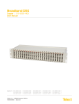
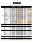
BCS HD Low-Profile Modular DSX-3 System
Copper :: 010-4801-4848, 010-0000-3248, 010-0000-2448
User Manual
Applies to :: 010-4801-4848 :: 010-0000-3248 :: 010-0000-2448 :: 010-4801-0407 :: 010-4801-0401 :: 010-4801-0410
© Telect, Inc., All Rights Reserved, 139255-2 A0.1
1.509.926.6000 :: telect.com
BCS HD Low-Profile Modular DSX-3 Systems
Copper :: 010-4801-4848, 010-0000-3248, 010-0000-2448
Table of Contents
Chapter 1: Description����������������������������������������������������������������������������������������������������������1
1.1 Broadband DSX��������������������������������������������������������������������������������������������������������������1
1.1.1 Capabilities�������������������������������������������������������������������������������������������������������������1
1.1.2 Features������������������������������������������������������������������������������������������������������������������1
1.1.3 Part Numbers����������������������������������������������������������������������������������������������������������1
1.2 Main Assemblies�������������������������������������������������������������������������������������������������������������2
1.2.1 24-Position Chassis������������������������������������������������������������������������������������������������2
1.2.2 32-Position Chassis������������������������������������������������������������������������������������������������3
1.2.3 48-Position Chassis������������������������������������������������������������������������������������������������4
1.2.4 Backplane���������������������������������������������������������������������������������������������������������������5
1.2.5 DSX Module������������������������������������������������������������������������������������������������������������5
1.3 Specifications������������������������������������������������������������������������������������������������������������������6
1.3.1 Electrical�����������������������������������������������������������������������������������������������������������������6
1.3.2 Environmental���������������������������������������������������������������������������������������������������������6
1.3.3 Agency Approvals���������������������������������������������������������������������������������������������������6
1.3.4 Physical - 24-Position Chassis, Fully Loaded��������������������������������������������������������� 7
1.3.5 Physical - 32-Position Chassis, Empty������������������������������������������������������������������� 8
1.3.6 Physical - 48-Position Chassis, Fully Loaded����������������������������������������������������9-10
Chapter 2: Installation��������������������������������������������������������������������������������������������������������� 11
2.1 Installation Considerations�������������������������������������������������������������������������������������������� 11
2.1.1 Location and Space���������������������������������������������������������������������������������������������� 11
2.1.2 Tools and Equipment��������������������������������������������������������������������������������������������� 11
2.1.3 Technical Support�������������������������������������������������������������������������������������������������� 11
2.1.4 Inspection�������������������������������������������������������������������������������������������������������������� 11
2.2 Installation Procedure for 010-0000-2448, 010-0000-3248�������������������������������������12-13
2.3 Installation Procedure for 010-0000-4848�������������������������������������������������������������������� 13
Chapter 3: Electrical Operation�������������������������������������������������������������������������������������������14
3.1 Power����������������������������������������������������������������������������������������������������������������������������14
3.1.1 Tracer Lamp����������������������������������������������������������������������������������������������������������14
Chapter 4: Service��������������������������������������������������������������������������������������������������������������16
4.1 Owner Maintenance������������������������������������������������������������������������������������������������������16
4.2 In-Warranty Service������������������������������������������������������������������������������������������������������16
4.3 Out-Of-Warranty Service����������������������������������������������������������������������������������������������16
4.4 Repacking for Shipment�����������������������������������������������������������������������������������������������16
4.5 Troubleshooting������������������������������������������������������������������������������������������������������������16
4.5.1 Cross-Connected Signals�������������������������������������������������������������������������������������16
© Telect, Inc., All Rights Reserved, 139255-2 A0.1
1.509.926.6000 :: telect.com
ii
BCS HD Low-Profile Modular DSX-3 Systems
Copper :: 010-4801-4848, 010-0000-3248, 010-0000-2448
List of Figures
Figure 1 - DSX 48-Position (010-4801-4848, Fully Loaded)������������������������������������������������� 1
Figure 1B - DSX 32-Position (010-0000-3248, Rear View)�������������������������������������������������� 1
Figure 2 - 24-Position, Part 010-0000-2448������������������������������������������������������������������������� 2
Figure 3 - 32-Position, Part 010-0000-3248������������������������������������������������������������������������� 3
Figure 4 - 48-Position, Part 010-0000-4848������������������������������������������������������������������������� 4
Figure 5 - Part 010-0000-4848, Rear View��������������������������������������������������������������������������� 5
Figure 6 - 6-Port Module, Part 010-4801-0410��������������������������������������������������������������������� 5
Figure 7 - 24-Position Chassis: All views������������������������������������������������������������������������������ 7
Figure 8 - 32-Position Chassis: All views������������������������������������������������������������������������������ 8
Figure 9 - 48-Position Chassis: Front Isometric and Side Views������������������������������������������ 9
Figure 10 - 48-Position Chassis: Rear, Top, and Front Views������������������������������������������� 10
Figure 11 - Connecting the Network Element on the 010-0000-2448 or 010-0000-3248�� 12
Figure 12 - Connecting Messenger Wire��������������������������������������������������������������������������� 12
Figure 13 - Connecting Ground Wire��������������������������������������������������������������������������������� 13
Figure 14 - Connecting the Network Element on the 010-0000-4848������������������������������� 13
Figure 15 - Connecting the Messenger Wire��������������������������������������������������������������������� 13
Figure 16 - Connecting the Ground Wire��������������������������������������������������������������������������� 13
Figure 17 - Closeup of Rear View of the Chassis�������������������������������������������������������������� 14
Figure 18- Tracer Lamp�����������������������������������������������������������������������������������������������������14
© Telect, Inc., All Rights Reserved, 139255-2 A0.1
1.509.926.6000 :: telect.com
iii
BCS HD Low-Profile Modular DSX-3 Systems
Copper :: 010-4801-4848, 010-0000-3248, 010-0000-2448
Chapter 1: Description
1.1 Broadband DSX
Telect’s Broadband Digital Signal Cross-Connect
(DSX) is a high-density device for crossconnecting
DS3, STS-1, and STS-3 signal types from broadband
equipment, such as digital radio, fiber-optic multiplexers,
and 3:3 or 3:1 DCS.
Figure 1 - DSX 48-Position
(010-4801-4848, Fully Loaded)
1.1.1 Capabilities
• Virtually “hitless” patching with terminate-before
-break TwistLok™ (TLJ™) jacks
• Backplane that can be pre-terminated and
cross-connect assignments pre-wired
• Bidirectional monitoring
1.1.2 Features
• Plug-in DSX cards to turn up circuit
• Up to 48 modules (010-0000-4848 is 6” x 23” chassis)
• Industry-standard patch cords
Figure 1B - DSX 32-Position
(010-0000-3248, Rear View)
• Mini-WECO jacks on modules and BNC on the rear
of the chassis
• Cable tie-down bars
1.1.3 Part Numbers
The information in this manual applies to the following part numbers:
Chassis #
Height
Width
Positions
Connectors
Tracer Lamp Terminations
010-0000-3248
3.5”
23”
32
BNC
PJ
010-0000-2448
010-0000-4848
3.5”
6”
19”
23”
24
48
BNC
PJ
BNC
PJ
Module #
Jacks
# of Ports
010-4801-0401
Mini-WECO
4
010-4801-0407
010-4801-0410
Mini-WECO
3
Mini-WECO
© Telect, Inc., All Rights Reserved, 139255-2 A0.1
1.509.926.6000 :: telect.com
6
1
BCS HD Low-Profile Modular DSX-3 Systems
Copper :: 010-4801-4848, 010-0000-3248, 010-0000-2448
1.2 Main Assemblies
1.2.1 24-Position Chassis
˿
Module Plug-in Connector (Inside View of Backplane)
Cable Ring
˿
˿
Rear Tie-down Bars
˿
˿
Module
Insertion Guide
Figure 2 - 24-Position, Part 010-0000-2448
© Telect, Inc., All Rights Reserved, 139255-2 A0.1
1.509.926.6000 :: telect.com
2
Mounting
Bracket
BCS HD Low-Profile Modular DSX-3 Systems
Copper :: 010-4801-4848, 010-0000-3248, 010-0000-2448
1.2.2 32-Position Chassis
˿
Module Plug-in Connector (Inside View of Backplane)
˿
Rear Tie-down Bars
˿
Cable Ring
˿
˿
Module
Insertion Guide
Figure 3 - 32-Position, Part 010-0000-3248
© Telect, Inc., All Rights Reserved, 139255-2 A0.1
1.509.926.6000 :: telect.com
3
Mounting
Bracket
BCS HD Low-Profile Modular DSX-3 Systems
Copper :: 010-4801-4848, 010-0000-3248, 010-0000-2448
1.2.3 48-Position Chassis
˿
Module Plug-in Connector (Inside View of Backplane)
˿
Rear Tie-down Bars
˿
Cable Ring
˿
˿
Module
Insertion Guide
Figure 4 - 48-Position, Part 010-0000-4848
© Telect, Inc., All Rights Reserved, 139255-2 A0.1
1.509.926.6000 :: telect.com
4
Mounting Bracket
BCS HD Low-Profile Modular DSX-3 Systems
Copper :: 010-4801-4848, 010-0000-3248, 010-0000-2448
1.2.4 Backplane
Figure 5 - Part 010-0000-4848, Rear View
1.2.5 DSX Module
Designation Label
& Holder
˿
Figure 6 - 6-Port Module, Part 010-4801-0410
© Telect, Inc., All Rights Reserved, 139255-2 A0.1
1.509.926.6000 :: telect.com
5
BCS HD Low-Profile Modular DSX-3 Systems
Copper :: 010-4801-4848, 010-0000-3248, 010-0000-2448
1.3 Specifications
1.3.1 Electrical
Digital Signal: E3 (34.368 Mbps), T3 (44.736 Mbps), STS-1 (51.84 Mbps), or STS-3 (155 Mbps)
Insertion Loss: 0.6 dB ±0.55, 8 MHz to 240 MHz, at signal rate
Return Loss: ≤ -15 dB, 8 MHz to 240 MHz, STS-3 signal rate, ≤ -26 dB, T3/E3/STS-1 signal rates
Crosstalk: ≤ -60 dB, 8 MHz to 240 MHz, at signal rate
Monitor Level: 21 ±1.5 dB below signal level
Contact Resistance: ≤ 0.01Ω
Characteristic Impedance: 75Ω
Tracer Lamp LED: Draws 9 mA
1.3.2 Environmental
Operating Temperature: –41º to 104ºF (5º to 40ºC)
Thermal Shock: Per MIL-STD 202, method 107D
Humidity: To 95% non condensing (operating and non-operating)
1.3.3 Agency Approvals
NEBS Level III Certification
© Telect, Inc., All Rights Reserved, 139255-2 A0.1
1.509.926.6000 :: telect.com
6
BCS HD Low-Profile Modular DSX-3 Systems
Copper :: 010-4801-4848, 010-0000-3248, 010-0000-2448
1.3.4 Physical - 24-Position Chassis, Fully Loaded
Figure 7 - 24-Position Chassis: All views
© Telect, Inc., All Rights Reserved, 139255-2 A0.1
1.509.926.6000 :: telect.com
7
BCS HD Low-Profile Modular DSX-3 Systems
Copper :: 010-4801-4848, 010-0000-3248, 010-0000-2448
1.3.5 Physical - 32-Position Chassis, Empty
11.626
6.090
8.76
3.450
Front Isometric View
˿
Left Side View
Rear View (Rotated)
Product ID/Serial Number
74.60
29.370
54.28
21.370
9.86
3.880
10.16
4.000
24.38
9.599
Top View
58.34
22.970
1.27
.500
7.62
3.000
3.18
1.250
Front View
Figure 8 - 32-Position Chassis: All Views
© Telect, Inc., All Rights Reserved, 139255-2 A0.1
1.509.926.6000 :: telect.com
8
BCS HD Low-Profile Modular DSX-3 Systems
Copper :: 010-4801-4848, 010-0000-3248, 010-0000-2448
1.3.6 Physical - 48-Position Chassis, Fully Loaded
˿
Cable Tie-down Bars
Front Isometric View
Side View
Figure 9 - 48-Position Chassis: Front Isometric and Side Views
© Telect, Inc., All Rights Reserved, 139255-2 A0.1
1.509.926.6000 :: telect.com
9
BCS HD Low-Profile Modular DSX-3 Systems
Copper :: 010-4801-4848, 010-0000-3248, 010-0000-2448
Figure 10 - 48-Position Chassis: Rear, Top, and Front Views
© Telect, Inc., All Rights Reserved, 139255-2 A0.1
1.509.926.6000 :: telect.com
10
BCS HD Low-Profile Modular DSX-3 Systems
Copper :: 010-4801-4848, 010-0000-3248, 010-0000-2448
Chapter 2: Installation
2.1 Installation Considerations
!
CAUTION
!
CAUTION
CAUTION! Only qualified technicians may install and maintain this product.
CAUTION! Do not supply power until all connections are made in accordance with requirements specified
in local electrical codes. Protect this equipment with an approved fuse or breaker sufficiently rated to
interrupt power at -48 Vdc at 2 amps, or as specified on the device. Only use components and crimping
tools approved by agencies or certifying bodies recognized in your country or region such as Underwriter's
Laboratories (UL), TUV, etc.
!
CAUTION
CAUTION! This equipment is intended for installation in locations accessible only to qualified persons.
These instructions presume that you have verified that the Telect equipment being installed is compatible with
the rest of the system including power, ground, circuit protection, signal characteristics, equipment from other
vendors, and local codes or ordinances.
2.1.1 Location and Space
Depending on chassis size, the Broadband DSX mounts in 19" or 23" WECO-spaced racks (1-inch-on-center
mounting holes) and uses 3.5" or 6" of vertical space.
2.1.2 Tools and Equipment
Installation requires no special tools or equipment.
2.1.3 Technical Support
Please use the online request from at www.telect.com under Support\Technical Support or call Telect directly
at 1-509-921-6161.
2.1.4 Inspection
Compare the contents of the Broadband DSX shipping container with the packing list. Call Telect if you are
missing anything.
NOTE: Telect is not liable for shipping damage. If the shipping container is damaged, keep it for carrier’s inspection.
Notify the carrier and call Telect’s Customer Service Department at 1-800-551-4567 or 1-509-926-6000. Keep the
container until you have checked equipment operation. Contact Telect if there are any problems with the equipment.
Use the original, undamaged container if instructed to return the DSX to Telect.
© Telect, Inc., All Rights Reserved, 139255-2 A0.1
1.509.926.6000 :: telect.com
11
BCS HD Low-Profile Modular DSX-3 Systems
Copper :: 010-4801-4848, 010-0000-3248, 010-0000-2448
2.2 Installation Procedure for 010-0000-2448, 010-0000-3248
1. Mount the Broadband DSX chassis to the rack with the four mounting screws that come with the equipment.
2. Attach tie-down bar mounting plate and tie-down bars and rings.
3. Starting with the lowest Broadband DSX in the chassis and working up, connect the network element (NE)
equipment to the lower pairs of connectors.
4. Secure the cables as required.
5. Install the cross-connects at the upper pairs of connectors, connecting “IX” of one piece of equipment to “OX”
of another. The equipment must have both cross-connects: “IX” of Equipment A to “OX” of Equipment B, and
“IX” of B to “OX” of A.
Figure 11 - Connecting the Network Element on the 010-0000-2448 or 010-0000-3248
6. Connect the messenger wire to one of the pin
sockets or wire wrap pins that pertain to the IX
and OX of a crossconnect pair.
7. Secure cross-connect cables from other
Broadband DSXs to the upper tie-down bar.
8. Slide the plastic designationlabel holders onto
the DSX modules.
© Telect, Inc., All Rights Reserved, 139255-2 A0.1
1.509.926.6000 :: telect.com
Figure 12 - Connecting Messenger Wire
12
BCS HD Low-Profile Modular DSX-3 Systems
Copper :: 010-4801-4848, 010-0000-3248, 010-0000-2448
9. Connect a ground wire (14 AWG, minimum) with #8
screw ring terminal to the ground lug.
10. Connect the office battery to the Power/Terminal
Screws.
11. Insert the appropriate DSX modules to turn up the
circuits you want.
12. Fill out the designation labels and insert them into
the plastic holders on the DSX modules.
2.3 Installation Procedure for 010-0000-4848
Figure 13 - Connecting Ground Wire
1. Mount the Broadband DSX to the rack with the four
mounting screws that come with the equipment.
2. Attach the tie-down bar mounting plate and tie
-down bars and rings.
3. Connect the network element (NE) equipment to
the I and O BNC connectors.
4. Secure the cables as required.
5. Install the cross-connects, connecting “IX” of one
piece of equipment to the “OX” of another. The
equipment must have both cross-connects:
“IX” of Equipment A to “OX” of Equipment B, and
“IX” of B to “OX” of A.
6. Connect the messenger wire to one of the pin
sockets or wire wrap pins that pertain to the IX and
OX of a cross-connect pair.
Figure 14 - Connecting the Network Element
on the 010-0000-4848
7. Secure cross-connect cables from other Broadband
DSXs to the upper tie-down bar.
8. Slide the plastic designation-label holders onto the
DSX modules.
9. Connect a ground wire (14 AWG, minimum) with a
#8 screw ring terminal to the ground lug.
Figure 15 - Connecting the Messenger Wire
10. Connect the office battery to the Power/
Terminal screws.
11. Insert the appropriate DSX modules to turn up the
circuits you want.
12. Fill out the designation labels and insert them into
the plastic holders on the DSX modules.
Figure 16 - Connecting the Ground Wire
© Telect, Inc., All Rights Reserved, 139255-2 A0.1
1.509.926.6000 :: telect.com
13
BCS HD Low-Profile Modular DSX-3 Systems
Copper :: 010-4801-4848, 010-0000-3248, 010-0000-2448
Chapter 3: Electrical Operation
3.1 Power
The Broadband DSX is passive equipment. It accepts -48V office battery power to turn on the tracer lamp (TL)
LED on the front of the DSX modules. This power connects to the power terminal at the back of the equipment.
The strip terminates a bus on the chassis backplane; all DSX module connectors on the backplane tap into the
signal lines of this bus.
Figure 17 - Closeup of Rear View of the Chassis
3.1.1 Tracer Lamp
The TL turns on only when a plug is inserted into one of the monitor jacks on the front of a DSX module.
Figure 18 - Tracer Lamp
Tracer Lamps of cross-connected modules can also be connected by attaching the messenger wire to the back
plane pin sockets that correspond to each of the connected modules. When one TL turns on, the other flashes for
about 30 seconds and then its light becomes steady.
© Telect, Inc., All Rights Reserved, 139255-2 A0.1
1.509.926.6000 :: telect.com
14
BCS HD Low-Profile Modular DSX-3 Systems
Copper :: 010-4801-4848, 010-0000-3248, 010-0000-2448
This page intentionally left blank.
© Telect, Inc., All Rights Reserved, 139255-2 A0.1
1.509.926.6000 :: telect.com
15
BCS HD Low-Profile Modular DSX-3 Systems
Copper :: 010-4801-4848, 010-0000-3248, 010-0000-2448
Chapter 4: Service
!
CAUTION
CAUTION! Only qualified technicians may install and maintain this product.
4.1 Owner Maintenance
Telect’s Broadband DSX does not require preventive maintenance. If you encounter technical difficulties, please
use the online request form at www.telect.com under Support\Technical Support or call Telect directly
at 1.509.926.6000.
4.2 In-Warranty Service
Contact Telect at 1.509.926.6000 or e-mail us at [email protected]. Telect will ship a new replacement product,
along with a return shipping label and authorization information. When you receive your replacement product,
pack up the defective product and return it to Telect using the return label, box and any additional information provided.
4.3 Out-Of-Warranty Service
Follow the In-Warranty directions above. Telect charges a processing fee for out-of-warranty service, and you
must submit a Purchase Order along with a Return Material Authorization (RMA) before returning equipment. The
processing fee guarantees a repair estimate and is credited against actual material and labor costs. Call Telect's
support center at 1.509.926.6000 for more information.
4.4 Repacking for Shipment
1. Tag the equipment showing owner’s name, address, and telephone number, together with a detailed
description of the problem.
2. Use the original shipping container if possible. If you do not have it, package the equipment in a way to
prevent shipping damage. Include the RMA inside the container and legibly print the RMA number on the
outside of the package, near the shipping address.
3. Insure the package
4.5 Troubleshooting
4.5.1 Cross-Connected Signals
Check for correct and firm cable connections at the termination and cross-connect points of the BCS-HD.
© Telect, Inc., All Rights Reserved, 139255-2 A0.1
1.509.926.6000 :: telect.com
16
BCS HD Low-Profile Modular DSX-3 Systems
Copper :: 010-4801-4848, 010-0000-3248, 010-0000-2448
This page intentionally left blank.
© Telect, Inc., All Rights Reserved, 139255-2 A0.1
1.509.926.6000 :: telect.com
17