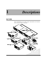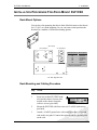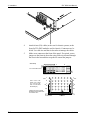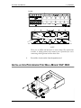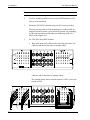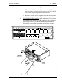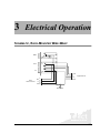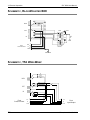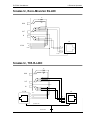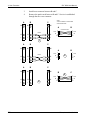
1
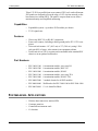
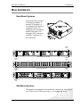
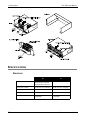
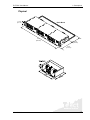
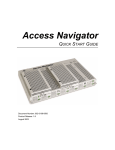
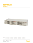
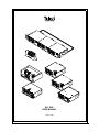
®
®
ELF DSX
USER MANUAL
124317-5 A0
ELF DSX User Manual
Document Number 124317-5 A0
Copyright© 2001, Telect, Inc., All Rights Reserved.
Telect® and Connecting the Future® are registered trademarks of Telect, Inc., 2111 N. Molter Rd., Liberty Lake,
Washington 99019
Technical Support (USA):
By e-mail: [email protected]
By phone: 888-821-4856 or 509-921-6161
Note:
Telect assumes no liability from the application or use of these products. Neither does Telect convey any license under its patent rights nor the patent rights of others. This document and the products described herein are subject to
change without notice.
ii
Telect, Inc.
124317-5 A0
Contents
1 Descriptions
ELF DSX ..................................................................................... 1-1
Capabilities ............................................................................ 1-2
Features.................................................................................. 1-2
Part Numbers ......................................................................... 1-2
System-Level Applications.......................................................... 1-2
Main Assemblies.......................................................................... 1-3
Rack-Mount Systems ............................................................. 1-3
Wall-Mount Systems ............................................................. 1-3
Specifications............................................................................... 1-4
Electrical ............................................................................... 1-4
Physical ................................................................................. 1-5
2 Installation
Installation Considerations .......................................................... 2-1
Location and Space................................................................ 2-1
Tools and Equipment ............................................................. 2-2
Technical Support (USA) ...................................................... 2-2
Inspection..................................................................................... 2-2
Installation Procedure for Rack-Mount ELF DSX ...................... 2-3
Rack-Mount Options.............................................................. 2-3
Rack Mounting and Cabling Procedure................................. 2-3
Installation Procedure for Wall-Mount ELF DSX ....................... 2-5
3 Electrical Operation
Schematic, Rack-Mounted Wire-Wrap ........................................ 3-1
Schematic, Rack-Mounted BNC.................................................. 3-2
Schematic, TFA Wire-Wrap......................................................... 3-2
Schematic, Rack-Mounted RJ-48C.............................................. 3-3
Schematic, TFA RJ-48C .............................................................. 3-3
124317-5 A0
®
®
iii
4 User Functions
Monitoring ................................................................................... 4-1
Patch And Roll............................................................................. 4-1
5 Service
Owner Maintenance ..................................................................... 5-1
In Case Of Difficulty ................................................................... 5-1
Technical Support (USA) ...................................................... 5-1
In-Warranty Service ..................................................................... 5-2
Out-Of-Warranty Service............................................................. 5-2
Repacking For Shipment ............................................................. 5-2
iv
Telect, Inc.
124317-5 A0
1
Descriptions
ELF DSX
Telect’s ELF DSX serves as a small, “edge” connection device in locations
where equipment density is important.
®
®
124317-5 A0
1-1
1 Descriptions
ELF DSX User Manual
Telect’s T1/E1 low-profile front cross connect (FXC) rack- and wall-mount
ELF panels are designed to fit on the edge of a 3G wireless network, at the
base transceiver station (BTS). The panel’s compact front access allows
maximum density and simplified monitoring.
Capabilities
•
•
Expandable system—up to three ELF modules per chassis
T1/E1 signal rates
•
•
Wire-wrap, BNC I/O, or RJ-48C connections.
Front cross-connect, including a shield ground pin for ITU G.703 compiance.
Universal rack mount—19" (48.3 cm) or 23" (58.4 cm), using 1 EIA
rack unit (RU) of space. Also mounts in an equipment cabinet.
Total Front Access (TFA) versions can be mounted in the standard ELF
chassis or in an optional wall bracket.
Features
•
•
Part Numbers
•
•
•
•
•
•
•
•
ELF-1008-1100
ELF-1008-1200
ELF-1008-1800
ELF-3006-1100
ELF-3006-1800
ELF-0000-2400
ELF-0000-0600
ELF-0005-0001
8-termination module, wire-wrap I/O
8-termination module, BNC I/O
8-termination module, RJ-48C
6-termination module, wire-wrap TFA
6-termination module, RJ-48C TFA
3-module chassis for all ELF modules
Wall bracket for ELF-3008-1100 & ELF-3006-1800
12 x 4 Alarm Pin Block
SYSTEM-LEVEL APPLICATIONS
•
•
•
•
1-2
Wireless base transceiver station (BTS)
Customer premises
Controlled environment vault
Co-location
Telect, Inc.
124317-5 A0
ELF DSX User Manual
1 Descriptions
MAIN ASSEMBLIES
Rack Mount Systems
The chassis holds up to three
8-termination modules, 6terminal-TFA modules, or
12x4 alarm pin blocks for an
expandable system. The
backplanes of 8-termination
modules hold either wirewrap pins, BNC connectors,
or RJ-48C connectors for
I/O connections.
Ground
Stud
Cable
Tie-Down
Bar
Chassis Backplane, Wire-Wrap
Cable
Tie-Down
Bar
Chassis Backplane, BNC
7
8
5
6
3
4
1
2
Cable
Tie-Down
Bar
7
8
5
6
Ground
Stud
1
3
4
Ground
Stud
2
7
8
3
5
6
4
1
2
Chassis Backplane, RJ-48C
Wall-Mount Systems
The optional wall-mounted bracket holds one 6-termination, total front ac®
cess (TFA I/O & X-CON) wire-wrap or a 12 x 4 alarm pin block.
®
124317-5 A0
1-3
1 Descriptions
ELF DSX User Manual
SPECIFICATIONS
Electrical
E1
1-4
T1
Return Loss
12 dB 51 kHz to 102 kHz
18 dB 102 kHz to 2048 kHZ
14 dB 2048 kHz to 3073 kHz
26 dB 772 kHz
Interchannel Crosstalk
-60 dB at bit rate (2.048 Mbps)
-60 dB at bit rate (1.544 Mbps)
Adjacent Channel Crosstalk
-60 dB at bit rate (2.048 Mbps)
-60 dB at bit rate (1.544 Mbps)
Insertion Loss
0.5 dB at bit rate (2.048 Mbps)
0.5 dB at bit rate (1.544 Mbps)
Monitor Level
–20 dB ± 1.5 dB at bit rate
(2.048 Mbps)
–20 dB ± 1.5 dB at bit rate
(1.544 Mbps)
Telect, Inc.
124317-5 A0
ELF DSX User Manual
1 Descriptions
Physical
1.75 in.
(4.4 cm)
Rack Mount
19 in.
(48.3 cm)
3.5 in.
(8.9 cm)
5.5 in.
(14.0 cm)
®
®
124317-5 A0
1-5
1 Descriptions
1-6
ELF DSX User Manual
Telect, Inc.
124317-5 A0
2
Installation
INSTALLATION CONSIDERATIONS
!
CAUTION
CAUTION! This product must be installed and maintained only
by qualified technicians.
VORSICHT! Nur von qualifizierten Technikern installiert werden
und instand gehalten werden.
PRECAUCIÓN! Ser instalado y ser mantenido solamente por
los técnicos autorizados.
ATTENTION! Ce produit doit être installé et entretenu uniquement par des techniciens qualifiés.
!
ALERT
ALERT! These instructions presume you have verified that the
Telect equipment being installed is compatible with the rest of
the system, including power, ground, circuit protection, signal
characteristics, equipment from other vendors, and local codes
or ordinances.
Location and Space
•
•
124317-5 A0
The ELF DSX chassis mounts in a 19" (48.3 cm) or 23" (58.4 cm)
®
equipment rack (EIA or WECO) or inside an equipment cabinet. On
an
EIA rack, it takes up one RU of space (1.75"/4.4 cm).
The ELF DSX wall bracket requires 6" (15.2 cm) by 1.8" (4.5 cm)® of
wall space.
2-1
2 Installation
ELF DSX User Manual
Tools and Equipment
•
•
Standard and wire-wrap tools
A chassis ground wire—14 AWG minimum with ring terminal.
Use listed components (UL-recognized, CSA, ETL, TUV agency) and
crimping tools.
Technical Support (USA)
By e-mail: [email protected]
By phone: 888-821-4856 or 509-921-6161
INSPECTION
Compare the contents of the ELF DSX shipping container with the packing
list. Call Telect if you are missing anything.
NOTE
Telect is not liable for shipping damage.
If the shipping container is damaged, keep it for the carrier’s inspection.
Notify the carrier and call Telect’s Customer Service Department:
1-800-551-4567 or 1-509-926-6000
Keep the container until you have checked equipment operation. If you experience any kind of problem, call Telect’s Customer Service Department.
Use the original, undamaged container if you are instructed to return the
ELF DSX to Telect.
2-2
Telect, Inc.
124317-5 A0
ELF DSX User Manual
2 Installation
INSTALLATION PROCEDURE FOR RACK-MOUNT ELF DSX
Rack-Mount Options
You can leave the mounting brackets in their default location on the chassis
for 19" (48.3 cm) flush mounting. Or you can remove and reposition the
brackets for a number of different mounting options:
(End Views)
19" Orientation
(1)
23" Orientation
(2)
(3)
Bracket Position Mount Option
Flush
1A
Extended
1B
Recessed
2A
Recessed*
2B
Flush
3A
Extended
3B
*The recess is very slight at this
position, almost flush.
(A)
(B)
ELF DNX, Right-End View
ELF DSX, Right-End View
Rack Mounting and Cabling Procedure
Step
Action
1.
Insert one to three ELF DSX modules into the chassis. Secure each
module to the chassis faceplate
with two screws (provided).
2.
Mount the ELF DSX with four screws (#12 or M6, both sets are
provided).
®
3.
124317-5 A0
Attach a 14 AWG ground wire with a ring lug to the 8-32 ground
stud on the rear panel. Connect the opposite end to a ground point
®
on the rack.
2-3
2 Installation
ELF DSX User Manual
4.
Attach in/out (I/O) cables (at the rear for chassis systems; at the
front for TFA DSX modules used in chassis). Connectors are labeled. Use cable ties and the tie-down bar to manage the cables.
5.
Make cross-connects at the front of the panel. If required, secure
jumpers to the front tie-down bar using cable ties inserted through
the slots in the bar and then wrap the tie around the jumpers.
Wire Wrap
B A
A
B
A TO B IS EXAMPLE ONLY
T
T
R
R
T
T
R
R
OUT
Out T “A” to In T “B”
Out R “A” to In R “B”
In T “A” to Out T “B”
In R “A” to Out R “B”
SG to SG (E1)
OUT
IN
IN
SG
SG
JUMPER ROUTING SCHEME
BETWEEN PINS SHOWN HERE
IS EXAMPLE ONLY
Tie-Down Bar
2-4
Cable Tie
Telect, Inc.
124317-5 A0
ELF DSX User Manual
2 Installation
RJ-48C
NOTE
There are no LEDs and therefore no tracer lamp (TL) connections
to make. A shield ground cross-connect pin is provided for crossconnecting shield ground with the drain wire.
6.
Record the circuits on the front designation card.
INSTALLATION PROCEDURE FOR WALL-MOUNT ELF DSX
TFA ELF Module
Wall Bracket
®
®
124317-5 A0
2-5
2 Installation
ELF DSX User Manual
Step
Action
1.
Use four, suitable panhead screws to secure DSX bracket to wall.
Screws are not included.
2.
Mount the ELF DSX in bracket using two M3 screws provided.
The away-facing surfaces of the mounting ears on the module are
stripped of paint to ensure a good electrical ground. For grounding,
use the ring lug and star lockwasher provided along with a #14
AWG (min.) copper wire.
3.
For TFA Wire-Wrap DSX modules,
a. Wire-wrap in/out (I/O) cables to the left of the patch area. Use
cable ties and the tie-down bar to manage cables.
b. Make cross-connects at the right of the patch area. Again, use
cable ties and tie-down bar to manage cables.
The example below shows network element 1 (NE 1) cross-connected to NE 6.
2-6
Telect, Inc.
124317-5 A0
ELF DSX User Manual
2 Installation
NOTE
There are no LEDs and therefore no tracer lamp (TL) connections to make. A shield ground cross-connect pin is provided for
cross-connecting shield ground with the drain wire.
c. Record the circuits on the designation card and affix anywhere.
4.
For TFA RJ-48C DSX modules, make input/output (I/O) interconnections along the bottom row of RJ connectors and cross connections along the top row, as shown in the following illustration.
Record the circuits on the designation card and affix anywhere.
®
®
124317-5 A0
2-7
2 Installation
2-8
ELF DSX User Manual
Telect, Inc.
124317-5 A0
3
Electrical Operation
SCHEMATIC, RACK-MOUNTED WIRE-WRAP
MON
R
OUT
IN
Front
Cross-Connect
T Out
R
T In
R
SGnd
T
Out R
In T
R
SGnd
Equipment I/O
Shield Gnd
®
®
124317-5 A0
3-1
3 Electrical Operation
ELF DSX User Manual
SCHEMATIC, RACK-MOUNTED BNC
MON
R
XFR
OUT
OUT
IN
0Ω
IN
Front
Cross-Connect
T
Out R
In T
R
SGnd
120/75Ω
Shield Gnd
SCHEMATIC, TFA WIRE-WRAP
R2
R1
MON
OUT
IN
Front
Cross-Connect
3-2
OUT T
R
IN T
R
S. GND.
T OUT
R
T IN
R
S. GND.
Telect, Inc.
Front
Input/Output
124317-5 A0
ELF DSX User Manual
3 Electrical Operation
SCHEMATIC, RACK-MOUNTED RJ-48C
R2
R1
MON
OUT
IN
I/O
OUT T
R
IN T
R
S. GND.
X-CON
IN
T
R
OUT
T
R
8
7
6
5
4
3
2
1
S. GND.
SCHEMATIC, TFA RJ-48C
R2
R1
MON
OUT
IN
X-CON
I/O
1
2
3
4
5
6
7
8
R
T
R
T
OUT
IN
IN
OUT
T
R
T
R
8
7
6
5
4
3
2
1
®
RJ SHIELD GND.
®
CHASSIS GND.
124317-5 A0
3-3
3 Electrical Operation
3-4
ELF DSX User Manual
Telect, Inc.
124317-5 A0
4
User Functions
MONITORING
To monitor the OUT signal from an ELF DSX module, plug one end of a
single patch cord into the MON port and the other end into the monitoring
equipment. The MON port connection is nonintrusive.
PATCH AND ROLL
Patching maintains a circuit by temporarily cross-connecting to back-up
equipment so that technicians can repair or test the lines of the permanent
connection. Patching and rolling allows a circuit to be moved from an existing facility to a new or spare facility, including new permanent crossconnects.
NOTE
If you use a dual patch plug, remember to twist the plug on one end of the
cord so that it is reversed (i.e., turned upside down) from the other end.
Step
Action
1.
Patch B to spare facility C. Insert patch cords in C, then in B.
2.
Remove the cross connects between the A and B facilities.
®
®
124317-5 A0
4-1
4 User Functions
ELF DSX User Manual
3.
Install cross-connects between B and C.
4.
Remove the patch cords between B and C. Service is established
through the new cross-connects.
A
M
B
NOTE:
CROSS-CONNECTS ARE SHOWN
IN DIAGRAM FORM.
C
M
M
A
B
Cross-Connect
T
R OUT
T
R IN
SG
OUT T
Patch
O
O
O
I
I
I
R
IN T
R
SG
(E1)
1
A
M
B
C
M
M
A
B
OUT T
Patch
O
O
O
I
I
I
A
M
B
R
IN T
R
SG
2
C
M
M
B
3
OUT T
O
I
4-2
O
I
T
R OUT
T
R IN
SG
O
4
I
R
T
IN R
SG
(E1)
Telect, Inc.
C
T
R OUT
T
R IN
SG
124317-5 A0
5
Service
!
CAUTION
CAUTION! This product must be installed and maintained only
by qualified technicians.
VORSICHT! Nur von qualifizierten Technikern installiert werden
und instand gehalten werden.
PRECAUCIÓN! Ser instalado y ser mantenido solamente por
los técnicos autorizados.
ATTENTION! Ce produit doit être installé et entretenu uniquement par des techniciens qualifiés.
OWNER MAINTENANCE
Telect’s ELF DSX does not need preventive maintenance.
IN CASE OF DIFFICULTY
If problems occur after initial installation, check cable connections and
grounding as described in the installation instructions in Chapter 2.
Technical Support (USA)
®
By e-mail: [email protected]
By phone: 888-821-4856 or 509-921-6161
124317-5 A0
®
5-1
5 Service
ELF DSX User Manual
IN-WARRANTY SERVICE
Contact your Telect equipment distributor, or call a Telect Customer Service Representative:
1-800-551-4567
1-509-926-6000
Telect will repair or replace defective products within the limits of the warranty. See “Repacking for Shipment” in this section.
NOTE
Call a Customer Service Representative for a Return Material Authorization (RMA) before returning any equipment.
OUT-OF-WARRANTY SERVICE
The procedure for out-of-warranty service is the same as for in-warranty
service, except that Telect charges a processing fee, and you must submit a
Purchase Order along with a Return Material Authorization (RMA) before
returning equipment. Call a Customer Service Representative for help getting these forms.
The processing fee guarantees a repair estimate and is credited against actual material and labor costs.
REPACKING FOR SHIPMENT
Step
Action
1.
Tag the equipment showing owner’s name, address, and telephone
number, together with a detailed description of the problem.
2.
Use the original shipping container if possible. If you do not have
it, package the equipment in a way to prevent shipping damage. Include the RMA inside the container and legibly print the RMA
number on the outside of the package, near the shipping address.
3.
Insure the package.
NOTE
Telect is not liable for shipping damage.
5-2
Telect, Inc.
124317-5 A0
Telect, Inc.
2111 N. Molter Rd.
P.O. Box 665, Liberty Lake, WA 99019
509-926-6000, 800-551-4567, Fax 509-926-8915
E-mail: [email protected] Internet: http://www.telect.com