1
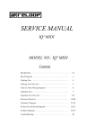
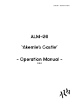
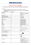
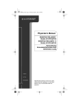
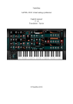
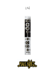
Spring Reverb
Documentation
PCB rev 2.1
Summer 2013
by Tom Whitwell
A flexible, easy-to-build voltage controlled DIY
mono spring reverb module.
It’s a simple build, but there are quite a few
options. The more of this document you read
before you start, the less likely you are to
make a mistake.
Block Diagram
Tilt EQ
Spring Tank
Crossfade in
Audio in
Crossfader
CV in
Attenuverter
Blend out
Blend Level
• Works with a variety of spring reverb tanks, or
• 6hp wide (NB: If using the brick, mounted
• Vactrol crossfade between dry and wet
• Tilt EQ on the reverb send to tune the voice of
• Around 60mm deep including a phono plug
with the Accutronics BTDR-2 reverb ‘brick’
designed by Brian Neunaber
the reverb, from warm and deep to bright and
light
horizontally, the brick extends 5mm over the
PCB to the left of the module, around 25mm
back from the front panel, so mount the
reverb next to a shallow module)
for the reverb tank coming from the back
• X-Fade input so the module can also be used
• Just 35mm deep if you mount the reverb
• Attenuverter on the crossfade CV input;
• Modular PCB design; the back PCB is a self
• Options for reverb tank connection and
• Power consumption: Around 25 ma (spring) or
as a standalone vactrol crossfader
centre = off; anticlockwise = inverted signal;
clockwise = normal signal
placement; front or rear panel phono sockets
and PCB connections
• Optional (unbuffered) PCB connections for
100% wet and post-EQ dry outputs
connections on the front panel
contained system to drive a spring tank or
brick, making it easy to design simpler or
more complex reverb systems
75ma (brick)
Using the module, and
how to get the best
possible sound
I’m very happy with how this circuit sounds,
particularly in this demo: http://snd.sc/16o6GvG
But it’s not always easy to coax such smooth
tones from a spring reverb.
Don’t assume there is a fault with your module
if you don’t immediately get this kind of sound I made that mistake a few times on breadboard.
Here’s what I’ve learned about getting a good,
rich, warm, clean sound:
•What you get out depends on what you
put in. By far the biggest factor in the tone of the
reverb is - obviously - the tone being fed into it.
Software reverbs can put the same smooth
mushy sound over whatever your run into them.
This isn’t like that at all. Remember that it’s a
physical system moving about, driven by
magnets and electricity and springs.
the tank. Try shifting it through 90 degrees - on
whichever axis is practical - and often the hum
will drop. If you want to mount your tank inside a
case, experiment with the exact position to find
the quietest spot before fixing anything.
•Noise (hiss, white noise, not hum) is
caused by the high-gain op amp in the
recovery section. I’ve tried to reduce it as far
as possible by using low-impedance resistors. I
also tried two lower-gain op amps in series, which
seriously increased the noise. It may be that
using other dual op-amps could reduce this noise
even further. Or just think of it as tape hiss,
adding mojo.
•Spring reverb is chaotic and hard to
predict. Spring reverb is a strange, gnarly,
physical effect. When I tried to calibrate and
measure this circuit, I’d find that a sine wave at,
for example, 400hz, might barely excite the
springs at all, while a sine at 405hz would bust
them into fuzzy overdrive. Change a component,
and that response changes completely.
How to use the controls
I’ve found that smooth, clean, FM-ed sinewaves
work very well with the springs. On a ‘scope, the
output looks similar to the input, but more
complicated. On the other hand, square waves
try to bash the springs about. There’s no way that
a magnet can move a spring in anything like a
square wave, so the sound coming out will sound
little like a square wave. On a ‘scope, it’s more
like a filter or waveshaper.
Tilt
Small changes in the input sound can be
amplified and enhanced by the reverb.
Blend
•Choice of spring tank is not absolutely
critical. Big long six spring tanks will sound
bigger than small tanks, but I’ve found that - at
least with my limited selection - it is less
important than the other factors in this list. I got
pretty good reverb from the tiny plastic-boxed
new reverb that Belton are developing. You can
use EQ to compensate for the choice of tank to
some extent.
•Hum is caused (and can often be cured)
by the exact position of the tank. A reverb
tank is not unlike a big, highly amplified singlecoil guitar pickup. It will pick up 50/60hz mains
hum, particularly from transformers but probably
also from dimmer switches or fluorescent tubes.
That hum can often be stopped completely by
moving the tank away from the source or - often
more practically - by just changing the position of
Is a hifi-style EQ control based on the Ambler
circuit from 1970. It controls the signal sent to
the reverb, but has no effect on the dry signal.
At 12 o’clock, it is flat. Turned clockwise, it
boosts frequencies above 1,000hz, and cuts
frequencies below, by up to 8dB. Turned anticlockwise it cuts treble and boosts bass.
Controls the mix between clean and reverb
outputs, between dry and wet.
Control
This attenuates or inverts the CV input for the
blend control. At 12 o’clock, the CV is attenuated
(although if you want it to go completely, it’s
much easier to pull out the plug). Clockwise,
voltages are added to the blend control; high
input voltage = more reverb.
Anti-clockwise, they’re inverted; high input
voltage = less reverb.
X-Fade Input
Audio input here will replace the ‘wet’ reverb
signal in the crossfader, so the module can be
used as a standalone vactrol crossfader. Reverb
cannot be heard in this mode.
Building the module, and
choices you’ll need to
make before you start
Summary: Which values
should I use in the
unmarked spaces?
Before you start:
R7 depends on the vactrol.
Silonex 32SR3 = 470Ω
VTL5C3 = 47k
This PCB was built to be flexible. Before building,
you’ll have to take four decisions:
1: Tank or Brick?
The rear PCB has space for two separate drive &
recovery circuits; one for a reverb tank and one
for the Accutronics BTDR-2 reverb brick. The real
tank sounds better, but is physically bigger and
liable to hum. The brick is small and selfcontained, with a distinctive reverb based on
PT2399 delay chips.
Only build the circuit you will be using; If
building for a spring, ignore all components in
the ‘Brick’ area. If building for a brick, ignore
all components in the ‘Spring’ area.
It is also possible to build both circuits and
attach a switch in place of the jumper, to make
the module switchable between spring and brick
2: Which vactrol?
I’ve tested the circuit with VTL5C3 and Silonex
32SR3 vactrols. Both work well, and the value of
R7 needs to change:
Silonex 32SR3 470Ω
VTL5C3
47k
If you’re using a DIY vactrol or another brand, R7
should be chosen experimentally.
3. Where will you put the tank?
Inside the case The rear PCB has space for
phono sockets so that you can easily mount a
reverb tank either inside your case. There’s a risk
that your PSU will create hum that is picked up by
the tank, so experiment with the position and
orientation of the tank.
Out the back of the case If you have, or can
make, a suitable hole in the back of your case,
probably the best way to mount your tank is
outside Hanging a tank on the wall behind your
modular is a good way to cut down unwanted
vibration and avoid transformer hum, or the tank
can be left on top of the modular where then can
Tested spring specs are:
Input: 150Ω to 800Ω
Output: 2,250Ω to 2,575Ω
Insulated input, Grounded output
Beyond this range, you may need to do some
research or experimentation.
be shaken or strummed, or next to a speaker to
encourage feedback.
Out of the front of the case There is an
alternative version of the front panel with space
for two chassis-mounted phono sockets, so you
can patch the reverb tank into the front. It makes
for a snug front panel, but is the shallowest and
most skiff-friendly solution.
4a: Which Tank?
Short version: If you’re buying a new tank, I’d
recommend one of these fairly common models:
Accutronics 9EB2C1B A big 17” long reverb
tank with six springs.
Accutronics 8EB2C1B A smaller 10” version
with three springs. This is the tank from a Fender
Blues Junior amp, so is very common.
Other makes with the same number (i.e. MOD
8EB2C1B ) will work in the same way. The Ruby
3EB2C1B also looks nice.
Long version: The circuit has to be tailored to the
specific tank you use. It’s designed to be flexible,
but I don’t have hundreds of tanks lying around
to test it with.
Here’s how Accutronics/Belton codes work,
using the top tank as an example: 9EB2C1B
9 = The type of tank - the size, number of springs
etc. The circuit doesn’t care, but the sound
will be different.
This circuit is designed for C type tanks.
You might need to change the circuit
significantly to use other types.
That said, I’ve run my Blues Junior with the
reverb connected entirely the wrong way
round. It still worked, but certainly
sounded better the right way around.
1 = Locking Devices
B = Mounting orientation
The circuit doesn’t care about either of
these.
E = The input impedance;
A = 8-10 Ω
B = 150 - 190 Ω
C = 200 - 240 Ω
D = 250 - 310 Ω
E = 600 - 800 Ω
F = 1,475 - 1,925 Ω
The lower numbers are for Type 4 tanks,
higher for Type 8 & 9 tanks.
I’ve tested the circuit with various
impedances between 150 and 800 Ω.
Very low impedances may pull more
current than is available from the TL072
driver. Very high impedances might require
swapping the 10k trimmer for a 100k
trimmer.
B = Output Impedance
A = 500 - 600 Ω
B = 2,250 - 2,575 Ω
C = 10,000 - 12,000 Ω
I’ve only tested this circuit with B type
tanks. To adapt to other impedances you’d
need to change the values of R4 and R6.
4b: Which Brick?
There are two types of BTDR-2, depending on the
orientation. Either should work, but I’ve only
tested mine with a BTDR-2H, which lies parallel
to the PCB. The BTDR-2H will lie flat against the
back of the module, poking 5mm out of the left
side. The BTDR-2V will poke out of the back of
the module, extending the depth to around
60mm, and poking out a couple of millimeters
on the right hand side.
Either solder the brick directly to the PCB, which
is sturdy and low profile, or mount it in a bit of
female header, which adds a couple of
centimeters of depth. You probably wouldn’t
solder a chip worth £15 to a board without a
socket, would you?
Other Options
There are lots of options on the board to help you
build the reverb you want. All the sockets are pulled
out to tags on the front board. On the back board
there are outputs for the Post EQ, pre Reverb signal
and the Post reverb, pre Blend (100% wet) signal.
The rear board is a stand-alone reverb circuit, and the
front board should act as a modular-level EQ/Blend
circuit receiving power from the rear board.
2 = Decay Time
The circuit doesn’t care
C = Connections
A = Input Grounded / Output Grounded
B = Input Grounded / Output Insulated
C = Input Insulated / Output Grounded
D = Input Insulated / Output Insulated
NB: This board assumes Red=Output,
White=Input. Check your tank carefully.
The mini tanks that come with a Doepfer
A199 are sometimes coded differently.
Two Accutronics Blue
reverbs mounted in a
Hammond 1590XX
enclosure
Building the circuit
First run calibration
Bill of Materials
The calibration procedure is pretty
straightforward. If you don’t get it right first time,
go back and try again.
Most of the components are straightforward offthe-shelf parts, but the parallel PCB construction
means some components are very specific.
Sockets: The board is designed for 3.5mm
vertical jacks from Erthenvar or Thonk: model
PJ-301b. Other jacks may work, you’ll probably
need to wire the grounds together.
Potentiometers: Many 9mm vertical-mount
pots will fit on the board. Ideally, for maximum
module strength and stability, use pots that
mount to the panel, like the Alpha
RD901F-40-15R range available from Smallbear
(7mm mounting holes) or the Alps RK09L range
(9mm mounting holes)
The Blend pot is a voltage divider; any Linear pot
above 10k should work fine.
The CV Control attenuverter circuit is setup for a
50k pot, but I’ve used 100k in this slot without a
big impact.
The EQ circuit is set up for 10k with values
deliberately low to reduce noise. The circuit will
still work with other values, but the maximum
gain/cut may be more extreme, causing clipping
at some settings.
Op Amps: I specified a NE5532 for the EQ
section, but another TL072 will perform fine.
Unfortunately, I had little luck with the 5532 in
the critical spring recovery circuit, where the
lower noise would be helpful.
Vactrols:
The Silonex NSL-32SR3 has a white spot next to
the negative LED lead. The resistor leads are the
long thin ones. It’s a pretty tight fit, but the
Silonex and VTL5C3 will both fit on the board.
Once the module is fully built, with all the ICs in
their sockets, connect the module to power in
your case (or a separate PSU, if you have one).
Connect the spring reverb, being careful to get
the ins and outs the right way around. Don’t
screw the module into the case, you’ll need
access to the trimmer on the back.
•Connect an oscillator (ideally, the loudest sine
or triangle oscillator in your modular) to the
input.
•Connect the spring module output to your
output/mixer etc. Turn down your speakers! It
might get loud (it might also be very quiet)
•Set the oscillator to a middle/low frequency not sub-bass or very high pitched. Use an LFO
or a sequencer to constantly vary the pitch.
It doesn’t matter what it’s doing, but you
can’t really hear reverb on a static pitch.
•Set the CV and Tilt controls to 12 o’clock.
•Pan the blend control from 7 o’clock to 5
o’clock. You should be able to hear the clean, dry
signal at 7, and some kind of reverbed signal at
5. The reverb level might be very low or very loud
and distorted
•With the blend control at 5 o’clock (fully wet)
start moving the screw on the trim pot
clockwise.
•Listen to the reverb output, which should get
gradually either louder or quieter. If it doesn’t
change, start moving anticlockwise instead.
•Once you’ve got the hang of it, adjust the
reverb output until it just starts to distort, then
move back a bit so that it’s clean. You want it
as loud as possible, before distortion.
•Sweep the oscillator frequency up and down to
ensure it doesn’t distort. If you like, try a few
other oscillators in your system, or an oscillating
filter. Try whatever makes loud noises, to check it
won’t overdrive the spring.
•Sweep the blend control back to 100% dry.
Hopefully the dry and wet signal levels are
reasonably well balanced. If not, maybe push the
spring a little harder.
•After a while using the reverb, you may want to
go back to tweak the gain to taste.
LEDs
I’ve tested the board with both superbright and
regular 3mm LEDs, both seem to work fine. Be
careful about changing R11 to make the LED
brighter or dimmer as it will also change the
Vactrol LED brightness, potentially changing the
sound.
Populating the board Is hopefully
straightforward - build in the normal way,
resistors first, then capacitors, transistors,
sockets, hardware.
Front board = the board with sockets and pots.
Back board = the board with the power header.
Take care to study the silkscreen and
photographs to ensure components are on
the correct side. Both boards are double-sided
with components on both sides.
Particularly watch out for:
Type 1
PCB mounted phono
jacks for the spring
reverb tank on the
back
Type 2
An Accutronics
reverb ‘brick’ on the
back
•C12, the capacitor behind the the sockets on
the front board must be soldered before the
sockets
•The little 5 pin jumper that runs between the
front and back boards. Fit the male and female
halves together, put it in place, screw the boards
together, then solder. It doesn’t matter which
side is male or female.
•The back board is particularly double-sided; the
phono jacks, power header, trimmer, spring/brick
jumper and Brick are all mounted on the rear of
the back board. All other components, including
the rest of the power circuit are on the front of
the back board (between the two boards).
•I’ve accidentally soldered the power header to
the wrong side of the board before. It’s a real
pain to remove, and you have to sacrifice the
entire header to get it out.
It’s best to attach the LED right at the end. When
the front board is finished, put the LED into the
board (the longer lead goes into the + hole) but
don’t solder it. Loosely fit the front panel and
finger tighten a couple of nuts. Place the LED
Type 3
Phono jacks for the
PCB mounted on the
front panel
into the hole in the front panel, then solder it into
place before assembling the rest of the module.
Troubleshooting & mods
If the reverb level is too low after calibration,
consider changing R6 from 22k to 47k. R6 sets
the gain for the recovery circuit. The downside is
that this may cause increased hum and risk of
feedback.
It is possible to build both spring and brick
circuits, then attach a simple SPDT switch to the
jumper to switch between the two reverb types.
There are solder points on the back board for
Post EQ and 100% outputs which could be
pulled out to front panel sockets. These aren’t
buffered, so inserting a plug may change the
reverbed output. It would be easy enough to
hack two buffers from the TL072 in the ‘Brick’
section .
Patch ideas
Feedback
Ingredients; Spring Reverb + Filter with two input
channels (or filter + mixer)
1) Mult the Spring output to your speakers, and
to one input channel on the filter
2) Take the input source (if required) to the other
filter input.
3) Connect the filter output to the spring input.
4) Turn the volumes up carefully until the whole
circuit starts to feed back.
5) Bandpass filters are particularly fun here sweeping the filter tunes the feedback.
Gated / reverse reverb
Ingredients: Spring Reverb + Make Noise Maths
+ oscillator + VCA
1) Set up the right side of a Maths as an
envelope controlling the VCA to create a string
of short audio pulses / blips.
2) Connect EOC to the left side TRIG. Ensure left
side is not in cycle mode.
3) Connect the EOR output to the Spring CV
input. Set the blend to 7 o’clock and Control to
5 o’clock. Listen to the spring reverb output.
4) The Spring LED should now flash in time with
the audio pulses. Left hand Rise control sets
the length of the reverb.
5) Switch the Spring CV input from EOR to the
envelope out to get pseudo-reverse reverb.
Send your patch ideas to:
[email protected]
Open Source Hardware
This is an open hardware project. You are free to build this
hardware, sell it or make any changes to it, so long as you
share your changes and release them under the same license.
You should also credit me, Tom Whitwell. All of the original
design files (Eagle CAD, Illustrator etc) are shared. These files
are licensed under a Creative Commons Attribution Share-Alike
license, which allows for both personal and commercial
derivative works, as long as they credit me and release your
own interpretation under the same license.
This work is licensed under the Creative Commons
Attribution-ShareAlike 3.0 Unported License. To view a
copy of this license, visit http://creativecommons.org/
licenses/by-sa/3.0/ or send a letter to Creative
Commons, 444 Castro Street, Suite 900, Mountain
View, California, 94041, USA.