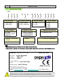
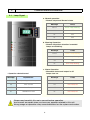
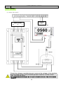
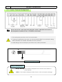
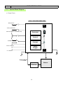
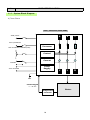
1
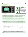
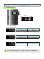
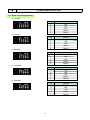
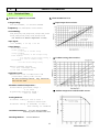
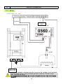
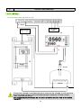
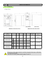
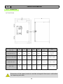
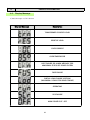
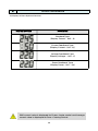
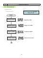
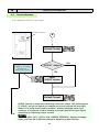
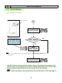
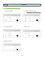
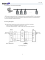
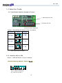
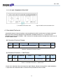
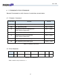
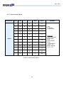
USER’S MANUAL
-DPR Series-
ABOUT PRODUCTS & SERVICES
Preface
We appreciate your purchasing our Digital Power Regulator. To avoid any trouble and for your
safety, please read this manual carefully before usage.
Charged Services
-Please read the manual in advance, as a service charge will be imposed for any service request
on a product without defects.
• A defect because a user doesn’t follow the instructions in the manual.
• A defect caused by not following rating, current capacity, or using
abnormal voltage or power.
• A defect caused by using components that our company doesn’t
designate.
• A defect caused by repair work of non-specialists.
• Alternation of fuse and consumption goods.
• A defect caused by natural calamities.
When a defect
occurs due to
mishandling or
improper repair.
* Term of guarantee of this product is 1 year from the purchase date.
Product installation environments
- Install this product vertically to activate ventilation and do not use it in or around flammable,
explosive, corrosive, and humid environments.
Symbol explanation
Mark
Name
Notice for electric shock
Notice
Warning
Danger
Grounding
Explanation
This symbol marks the parts where there is danger
of electric shock. Power must be turned off for
maintenance or repair of the product.
This symbol indicates risk of death or serious injury.
When the product is used incorrectly, it could
cause property damage.
To prevent malfunction, you must operate
grounding.
To prevent electric shock or noise from the
outside.
1
NOTICES FOR SAFETY
1. Install
1) Before installing this machine, install main power circuit breaker (NFB) and Magnetic switch
on the outside of the main body for safety.
2) If, after transport or storage in humid conditions, equipment could fail to meet all the safety
requirement, the install instruction shall 4 hour of operation to dry out the equipment and
restore it to normal condition.
2. Ground type 1 grounding or special type 3 grounding in the exterior box of the machine to
prevent electric shock.
3. Check that voltage of provided power is same as the voltage of the machine and the rated
current is not exceeding proper capacity of load current. Then, provide the power.
(It is recommended that you do not use a machine at over 70% of the rated current condition.)
4. Fuse
1) To prevent fire and to protect the machine, use a fast-acting fuse,which is designated by our
company. (Refer to the product label)
2) Must turn off the main power to exchange the fuse.
3) The fuse used must be of the specified rating (current, voltage, type) in order to prevent a fire
hazard.
5. Environments
1) Adjust ventilation and temperature so that temperature inside the control panel is
not over 45˚C.
2) Do not operate the machine where there is a risk of inflammability, explosiveness,
corrosion or humidity. (RH 70% below at 40℃)
3) The equipment must not be mounted on a surface of flammable material.
4) Live parts may need to be accessible, a statement requiring the fitting of a residual
current-opened circuit-breaker.
6. Disassembly or remodeling of the machine
1) Never change components voluntarily with the exception of changes of fuse or thyristor.
2) Our company can not guarantee operation of the machine when the volume of the
machine or component is altered voluntarily. When a problem occurs, please
contact our company’s A/S Department.
7. Check and repair
1) Before checking the machine, cut off the power and beware of electric shock.
2) Check fastening condition of bolts and nuts of terminal parts.
3) When bolts of terminal are loose, it could generate heat so wiring can be
damaged or fire can occur. Check this condition periodically.
8. This manual could be revised without notification for improvements of functions of the
machine.
9. Responsibilities and guarantee
1) Must preserve notices for handling, maintenance, and repair of the machine.
2) Our company is not responsible for damage, which occurs due to not following these
instructions..
Must preserve notices during handling the machine to ensure safety.
2
NOTICES FOR SAFETY
10. Cleaning
1) Do not spray water directly at the product. (A fire and electric shock will be occurred)
2) Please unplug the product
3) Do not use chemical liquid. Discoloration will be occurred.
4) Appropriate decontamination is carried out if hazardous material is split onto or into
the equipment.
5) Cleaning and decontamination necessary as a safeguard when laboratory heating
equipment and any accessories are maintained, required and transferred.
11. Protection against electric shock
1) The hazardous live parts are supplied from a circuit protected by a residual current
operated circuit-breaker which interrupts the supply at a differential current of 30mA
or less, or the installation such a circuit-breaker.
2) Conveyor belts, muffles, etc. which are conductive are connected to the protective
conductor terminal.
3) Please express clearly the necessary method to be carried for protection and method
for protection on where operator or other personnel can be contacted such as rechargeable
part or terminal connected to conductive circuit.
(ex. Isolation tools, isolation cable)
12. A/S Request
A/S Department
TEL (053) 857 – 4470, 4471
FAX (053) 857 – 4474
mail : [email protected]
Must preserve notices during handling the machine to ensure safety.
3
CONTENTS
PAGE
1. Identifying Label
--------------------------------------
5
2. Control Board Explanation
--------------------------------------
6
3. Control Mode Selection
--------------------------------------
8
4. Product Explanation
--------------------------------------
11
--------------------------------------
27
6. Repair and Maintenance
--------------------------------------
29
7. Inspection
--------------------------------------
30
1-1. Coding
4-1. Technical Data
4-2. Wiring
4-3. Control Terminal Arrangement
4-4. System Block Diagram
4-5. Dimensions
4-6. Display Message
5. Operation
5-1. Notices during operation
5-2. Wiring Control Terminal block
4
IDENTIFICATION
1
1-1. Identification Code
• CODE
S
P
P
2
–
0
2
① ② ③ ④
5
– 0
⑤
0
0
0
–
⑥ ⑦ ⑧⑨
0
0
0
0
⑩ ⑪ ⑫ ⑬
1. NO. OF PHASE
2. CONTROL METHOD
3. PRODUCT MODEL
4. RATED VOLTAGE
S. SINGE PHASE
T. THREE PHASE
P. PHASE-ANGLE
Z. ZERO-CROSSING
P. P TYPE
X. X TYPE
1.
2.
3.
4.
110V
220V
380V
440V
5. RATED CURRENT
6. FEEDBACK OPTION
7. COMMUNICATION OPTION
25A~800A
OVER 800A : PLEASE
CONSULT US
I. CURRENT FEEDBACK
V. VOLTAGE FEEDBACK
W. POWER FEEDBACK
C. COMMUNICATION
8. PARTIAL LOAD FAILURE
OPTION
9. OPTION
10~13. CUSTOMER’S REQUIREMENT
P. PARTIAL LOAD FAILURE
OTHER OPTION
CUSTOMER’S REQUIREMENT
Note
• Identification code is attached to the outer side of the unit.
• Please make sure this unit is the same as what you ordered by referring to identification code.
PARA-ENT , Republic of Korea
+82+53-857-4478
Product Power Regulator
Model
TZP2-110
Serial No 3G007
Power Rating : 110A @ 220V 60Hz
Input :
Firing Mode : Zero Crossing
Made In Korea
Fuse : SIBA 20 282 04-125A
Any other fuse invalidates warranty
H.page : www.paratec.co.kr , mail : [email protected] A/S 053)857-4470
Must preserve notices during handling the machine to ensure safety.
5
2
CONTROL BOARD EXPLANATION
2-1. Lamp Signal
a. Normal operation
: Normal output and Normal status
Message
Lamp
PILOT
Green Lamp Blinking
OC
OFF
OT
OFF
UL
OFF
b. Warning Operation
: Normal output but attention is needed.
Lamps are blinking.
▪ Operation related terms I
Message
Lamp
PILOT
Yellow Lamp Blinking
OC
Red Lamp Blinking
OT
OFF
UL
Red Lamp Blinking
c. Alarm Operation
: Abnormal status and output is off.
Lamps turn on.
Message
Explanation
Message
Lamp
PILOT
Operating status lamp
PILOT
Red Lamp ON
OC
Over Current
OC
Red Lamp ON
OT
Over Temp.
OT
Red Lamp ON
UL
Unbalanced Load
UL
Red Lamp ON
Please read carefully this user’s manual before operation.
And consult an expert when you have any question related to this unit.
Wrong usage or operation may cause bad effect on the system and worker.
63
2
CONTROL BOARD EXPLANATION
2-2. CONTROL Volume
▪ Operation related terms II
Volume
RESET
Explanation
RESTART :
On Alarming status
OUT PUT
Select maximum output
SOFT
Time for Soft Start &
Soft UP/DOWN
OC
Over Current prevention
function
Current Value
① Use RESET Button when you re-start the unit on the status of warning operation or alarm operation.
② OUTPUT Volume is used when selecting maximum output. FND shows figures 0~100(%),
set up the figure you require by turning volume left and right. After setting up the figure you want,
just push RESET BUTTON to complete selection.
③ Use SOFT Volume to adjust soft Start time(0~30sec). This setting time applies to soft up/down
also. On the adjusting soft volume, display FND shows you 0~30 sec. Then you can select
required time by turning volume switch left and right. After setting up the figure you want, just
push RESET BUTTON to complete selection.
④ On selecting OC (Over Current) Volume, FND shows 0~max (maximum amperage will be shown),
For example, OC volume is selected as 40 amp over current more than 52 amp(40amp X 1.3
normally 1.3 times of maximum amp. is the limit over current) flows, the unit notify the abnormal
status and does not allow the output. (OC lamp : Red lamp on)
Soft Start
Soft UP/DOWN
Please read carefully this user’s manual before operation.
And consult an expert when you have any question related to this unit.
Wrong usage or operation may cause bad effect on the system and worker.
7
CONTROL MODE SELECTION
3
3-1. Phase-Angle Control
-Front Control PartA. Function to SW1 ON/OFF
ON
OFF
Transformer Coupled Load
Resistive Load
ON
OFF
Soft UP/Down Operating
No Soft UP/DOWN operating
ON
OFF
Outer power volume
operating
No operating outer power
volume
B. Function to SW2 ON/OFF
C. Function to SW3 ON/OFF
Note : Please make sure SW2 is on when it is transformer coupled load.
8
3
CONTROL MODE SELECTION
3-2.Zero-Crossing Control
A. 1 mode
SW
ON/OFF
1
OFF
2
OFF
3
OFF
4
Option
5
Option
SW
ON/OFF
1
ON
2
3
OFF
OFF
4
Option
5
Option
SW
ON/OFF
1
OFF
2
3
ON
OFF
4
Option
5
Option
SW
ON/OFF
1
ON
2
3
ON
OFF
4
Option
5
Option
SW
ON/OFF
1
OFF
2
3
OFF
ON
4
Option
5
Option
B. 4 mode
C. 8 mode
D. 16 mode
E. 32 mode
9
3
CONTROL MODE SELECTION
F. 64 mode
SW
ON/OFF
1
ON
2
3
OFF
ON
4
Option
5
Option
SW
ON/OFF
1
ON
2
3
ON
ON
4
Option
5
Option
G. 128 mode
10
4
PRODUCT EXPLANATION
4-1. Technical Data
b. Characteristics
a. General Specifications
Voltage Rating :
200/220/240VAC, or 380/400/440VAC
■
Input/output characteristics
■
Gradient setting characteristics
■
Ambient temperature and allowable current
Frequency : 50/60Hz(Auto-selectable)
Current Rating :
25A,40A,55A,70A,90A,110A,130A,160A,200A
250A,320A,400A,500A,570A,800A,1100A
(all based on an ambient temperature of 50˚C)
Input Signal :
4 to 20mADC, 1 to 5V, 0 to 5V
Output Range :
• Phase Angle Control
Current feedback
- 0 to 100% of current rating
Voltage feedback
- 0 to 98%(95%) of the voltage rating
Power feedback
- [0 to 98%(95%) of the voltage rating] X
[0 to 100% of current rating]
Non Feedback
-0 to 98% of the voltage rating
• Zero Crossing Control
0 to 100% of voltage rating
(): In case of Three-Phase
Applicable Load :
• Resistive load or inductive load
(transformer primary side control)
For Zero Crossing Control, only resistive
load can be used.
Allowable Ambient Temperature :
• Performance guarantee range :
0 to +50˚C
• Operating guarantee range :
-15˚C to +55˚C
Cooling Method :
• Current rating of 70A or less :
Natural convection
• Current rating of 90A(25A) or more :
Fan Cooling as standard
Insulation Resistance : Over DC 500V 200MΩ
between power terminal and case
Mounting Method :
Vertical Method
11
4
PRODUCT EXPLANATION
4-2 . Wiring
a) Single phase, 25A ~ 70A
4~20mA
PCB Power
220V
TIC
⊙⊙
-
+
⊙⊙
Sensor
R
G
U
Heater
R
S
Main Power
Check the voltage of provided power is same as the voltage of the machine
and the rated current is not exceeding proper capacity of load current.
Then, provide the power.
(It is recommended that you do not use a machine at over 70% of the rated
current.)
12
4
PRODUCT EXPLANATION
4-2 . Wiring
b) Single phase, More than 90A (A Type)
4~20mA
PCB Power
220V
Main Power
R
S
TIC
⊙⊙
-
+
⊙⊙
Sensor
Heater
Check the voltage of provided power is same as the voltage of the machine
and the rated current is not exceeding proper capacity of load current.
Then, provide the power.
(It is recommended that you do not use a machine at over 70% of the rated
current.)
13
4
PRODUCT EXPLANATION
4-2 . Wiring
c) Single Phase, More than 90A(Type B)
4~20mA
PCB Power
220V
TIC
⊙⊙
-
+
⊙⊙
Sensor
Heater
R
S
Main Power
Check the voltage of provided power is same as the voltage of the machine
and the rated current is not exceeding proper capacity of load current.
Then, provide the power.
(It is recommended that you do not use a machine at over 70% of the rated
current.)
14
4
PRODUCT EXPLANATION
4-2 . Wiring
e) 3 Phase (all models)
PCB Power
220V
Main Power
R
S
T
TIC
⊙⊙
-
+
⊙⊙
Sensor
Heater
Check the voltage of provided power is same as the voltage of the machine
and the rated current is not exceeding proper capacity of load current.
Then, provide the power.
(It is recommended that you do not use a machine at over 70% of the rated
current.)
15
4
PRODUCT EXPLANATION
4-3 . Control Terminal Arrangement
Note
Please refer to the control input wiring diagram, which is attached to the inside of
the front panel or outside of case, to connect correct wires.
1. The main power must be cut off to connect wires.
2. To prevent malfunctions by noise, use the twist shield cable for control input wiring.
FIELD GROUND and SIGNAL GROUND must be operated.
3. Install wiring of the control input part far from the other power lines.
+
FG
Shield cable usage example
Danger, Warning/Notice
Danger, Warning : This symbol is displayed when there is risk of death or
severe injuries.
Notice : This symbol is displayed when there is a risk of property damage.
16
4
PRODUCT EXPLANATION
4-4 . System Block Diagram
a) Single Phase
220V, 380V,440V/50Hz,60Hz
RUN/STOP
R
AUTO/MANUAL
EXT.POTENTIO-METER(10K)
Processor
Control
ALARM
Current
220V POWER
Power
Supply
U
S - PHASE
FG
FG
Control Signal
4 ~ 20 mA
Temperature
Controller
17
Heater
4
PRODUCT EXPLANATION
4-4 . System Block Diagram
b) Three Phase
220V, 380V,440V/50Hz,60Hz
RUN/STOP
R
S
T
U
V
W
AUTO/MANUAL
EXT.POTENTIO-METER(10K)
Processor
Control
Current
ALARM
Power
Supply
220V POWER
FG
Control Signal
4 ~ 20 mA
Temperature
Controller
18
Heater
4
PRODUCT EXPLANATION
4-5 . Dimension
a) Single Phase
(Front-View)
(Side-View)
(Front-View)
- Models for less than 70 A -
Model
Type [A]
25, 40, 55, 70
- Models for more than 90 A -
W
H
D
W1
H1
Mounting
Bolt
Note
108
195
150
90
185
4 mm
Terminal
Block
4 mm
BUS-BAR
5 mm
BUS-BAR
5 mm
BUS-BAR
A
123
350
225
100
335
B
123
315
210
100
300
A
127
410
270
100
390
B
127
325
270
100
305
A
150
525
290
100
510
90,110, 130
160, 200, 250, 320
400, 500
B
(Side-View)
150
450
260
100
435
Dimensions of the upper products could be changed without pre-notification
for improving functions.
The sizes for A and B, please refer to page 12 and 13.
19
4
PRODUCT EXPLANATION
4-5 . Dimension
b) Three Phase
Model
Type [A]
W
H
D
W1
H1
Mounting
Bolt
Note
25, 40, 55, 70,
153
240
200
140
200
4 mm
Terminal
Block
90, 110, 130, 160
196
350
235
170
335
5 mm
BUS - BAR
200, 250, 320
250
415
270
200
395
5 mm
BUS - BAR
400, 500
330
530
310
220
510
6 mm
BUS - BAR
Dimensions of the upper products could be changed without pre-notification
for improving functions.
20
4
PRODUCT EXPLANATION
4-6 . Display Message
a) Main Message on FND Window
Display Message
Description
TRANSFORMER COUPLED LOAD
RESISTIVE LOAD
OVER CURRENT
OVER TEMPERATURE
HEAT FAILURE OR ALARM MESSAGE FOR
ABNORMAL STATUS OF POWER SYSTEM
FUSE FAILURE
PARTIAL LOAD FAILURE (OPTION)
(MAXIMUM 6 LOADS FOR SINGLE PHASE)
OPERATING
SCR FAILURE
MAIN POWER CUT-OFF
21
PRODUCT EXPLANATION
4
b) Display to Each Optional Function
Display Message
Description
Standard Type
(Display Current – Unit : A)
Current Feedback Type
(Display Current- Unit : A))
Voltage Feedback Type
(Display Voltage - Unit : V)
Power Feedback Type
(Display Power – Unit : Kw)
RMS current value is displayed for Phase-Angle control and Average
current value is displayed for Zero-Crossing control.
22
4
PRODUCT EXPLANATION
4-6 . Display Message
c) Display Example
① While initial starting
Example) Single Phase 220V 400A
display Message.
START
Type of product
: Single Phase 220V
Rated current
: Rated Current 400A
Type of Loads
: Transformer MODE
: Display actual current
Actual Current
A
23
PRODUCT EXPLANATION
4
4-6 . Display Message
② On adjusting ‘OUTPUT’ power volume
‘OUTPUT’ volume
A
Actual Current
Display % of output
Ex) 50% of
max. rated current
‘OUTPUT’ Adjust ?
NO
YES
Adjust
‘OUTPUT’ volume
Actual Current
OUTPUT Volume is used when selecting maximum output. FND shows figures
0~100(%), set up the figure you require by turning volume left and right.
When it is a feed-back type of product, display message varies from
minimum to maximum current (voltage or power against full input signal
according to adjusting output volume.
Example
When it is SPP2-040-I (220V, 40A, CURRENT FEEDBACK), display message
shows you from 0A to 40A according to adjusting output volume.
24
PRODUCT EXPLANATION
4
4-6 . Display Message
③ On adjusting ‘SOFT’ volume
‘SOFT’ volume
A
Actual Current
The display shows
‘SOFT START’ time by
second. But not shown
in three phase model
‘SOFT’ Adjust ?
NO
YES
Adjust
‘SOFT’ volume
Note
• ‘SOFT’ volume adjusting is only possible while the 2nd DIP switch is ON.
(see page 7)
Actual Current
Use SOFT Volume to adjust soft Start time(0~30sec). This setting time applies to soft
up/down also. On the adjusting soft volume, display FND shows you 0~30 sec. Then
you can select required time by turning volume switch left and right.
Note
• ‘SOFT’ volume adjusting is only possible while the 2nd DIP switch is ON. (see page 7)
25
PRODUCT EXPLANATION
4
4-6 . Display Message
④ On adjusting O.C. (over current) volume
‘O.C’ volume
A
Actual Current
‘O.C’ Adjust ?
NO
YES
Adjust
‘O.C’ volume
Actual Current
On selecting OC (Over Current) Volume, FND shows 0~max (maximum amperage will
be shown), For example, OC volume is selected as 40 amp over current more than
52 amp(40amp X 1.3V normally 1.3 times of maximum amp. Is the limit over current)
flows, the unit notify the abnormal status and does not allow the output. (OC lamp :
Red lamp on)
It is recommended to adjust O.C value should be 1.1 times than load ampere.
26
5
OPERATION
5-1 . Notices During Operation
1) Please watch out power supply terminals otherwise electric shock will cause.
2) Do not touch any of components in the unit because of high temperature. Especially
watch out not to put your finger or any stick in the cooling fan which turns too fast and
cause you any harm.
3) Do not operate or turn on the unit without load which results in over voltage and
damages transformer in unit.
4) Use only shield cable when wiring control terminal block.
5) Must not allow more than DC 5V or DC 20mA as input signal.
6) Installation Circumstances
① Mount this unit in the place where it ventilates well.
② Do not operate the machine where there is a risk of inflammability, explosiveness,
corrosion or humidity.
7) Ground type 1 grounding or special type 3 grounding in the exterior box of the machine to
prevent electric shock.
8) Check that voltage of provided power is same as the voltage of the machine and the rated
current is not exceeding proper capacity of load current. Then, provide the power.
(It is recommended that you do not use a machine at over 70% of the rated current condition.)
9) FUSE
① To prevent fire and to protect the machine, use a fast-acting fuse which is designated by our
company. (Refer to the product label)
② Must turn off the main power to exchange the fuse.
10) Disassembly or remodeling of the machine
① Never change components voluntarily with the exception of changes of fuse or thyristor.
② Our company can not guarantee operation of the machine when the volume of the
machine or component is altered voluntarily. When a problem occurs, please contact
our company’s A/S Department.
11) Check and repair
① Before checking the machine, cut off the power and beware of electric shock.
② Check fastening condition of bolts and nuts of terminal parts.
③ When bolts of terminal are loose, it could generate heat so wiring can be damaged or fire
can occur. Check this condition periodically.
27
OPERATION
5
5-2 . Wiring Control Terminal Block
1. 4~20mA (Auto Mode)
2. 4~20mA, Outer Power Volume
* Dip SW3 ON for Outer Power Volume
220V PCB
Power
220V PCB
Power
S
S
Only Single Phase
Only Single Phase
4. Manual Only
3. Relay Switch ON/OFF
220V PCB
Power
220V PCB
Power
S
Only Single Phase
5. Reset, Alarm Wiring
220V PCB
Power
S
Only Single Phase
S
Only Single Phase
28
6
REPAIR
FUSE Exchange
. The main power must be turned off to change the fuse.
. A fuse designated by our company must be used.
. Check that the fuse is fastened correctly after it is changed.
SCR Exchange
. The main power must be turned off to change the SCR element.
. An SRC designated by our company must be used.
. Check that the SCR is fastened correctly after changing it.
PCB UNIT
. The main power must be turned off to check PCB UNIT.
. PCB UNIT is manufactured through our company’s precise inspections.
When a problem occurs in the PCB UNIT, please contact our company’s
A/S Department.
Danger, Warning/ Notice
Danger, Warning: This symbol is displayed when there is risk of death or
serious injury.
Notice: When the product is used incorrectly, it could cause property damage.
29
7
INSPECTION
. The main power must be turned off to operate periodic inspection.
There is a risk of defect, electric shock, or fire.
Periodic Inspection
Please operate the periodic inspection, the following items, once every 6 months to maintain
the best condition and functions of the machine.
1. Cleaning
Dust may come from the outside. When there is dust, such as iron powder, insulation is
worse and causes inferiority of operation. So please clean the attached materials.
Remove the dust, on the components, using a soft brush or air.
2. Components fastening condition
Check the screw fastening condition of each connection part. The screw could be
loosened with time.
Fastened screw could cause damage by heat so it could cause control instability or
defects.
So periodic inspection is necessary to keep the normal condition.
3. Wiring condition check
Must check abnormality or modification of insulating covering of input and output wires
of the machine. When there is abnormality, please change the part.
4. Other check items
Must check the fastening and connection condition of connector and terminals in the
machine.
Danger, Warning/ Notice
Danger, Warning: This symbol is displayed when there is risk of death or
serious injury.
Notice: When the product is used incorrectly, it could cause property damage.
30
USER’S MANUAL
COMMUNICATION
MANUAL
-DPR Series(Appendix)
Ver 2.00
Contents
1. Summary of communication
------------------------
2
2. Wiring Diagram
------------------------
2
3. Communication parameter
------------------------
3
3.1 Contents of parameter
------------------------
3
3.2 Selecting Guide
------------------------
4
3.2.1 Baud Rates Selection
------------------------
4
3.2.2 Selecting ADD for DPR
------------------------
4
3.2.3 RS485 Communication Port
------------------------
5
------------------------
5
------------------------
6
4.1.1 General Command
------------------------
6
4.1.2 Error Repose
------------------------
6
------------------------
7
4.2.1 General Command
------------------------
7
4.2.2 Alarm Status Signal
------------------------
8
4. Standard Protocol
4.1 Communication Command
4.2 Command Signal
1
Ver 2.00
1. Summary of Communication
…
Fig.1 Connection to DPR
DPR Series is operated by Half-Duplex method controlled by RS485. And maximum
31 units of DPR series can be connected to supervisory system for communication
through adopting prepared Protocol.
2. Wiring Diagram
Wiring between supervisory system and power controller is as below
• Multi-access is available to maximum 31 units.
• Connect resistance(200Ω 1/4W) at the end of the each terminal
DPR
DPR
RTX+
RTX+
RTX+
RTX-
RTX-
RTX-
SG
SG
SG
Master
Resistance
(200Ω 1/4W)
SHIELD
type 3
grounding
type 3 grounding
Fig.2 Wiring Diagram
2
Resistance
(200Ω 1/4W)
Ver 2.00
3. Communication Parameter
3. 1 Contents of Parameter
Parameters to select condition of communication are as below.
Parameter
COM.P
BAUD
PTRY
SBIT
DLEN
Signification
Setting Value
Content
Default
Select Protocol
0
Standard Protocol
O
1
Standard Protocol + Check sum
X
2
19200bps
O
1
9600bps
X
0
2400bps
X
NONE
No Parity.
O
EVEN
Even Parity
X
ODD
Odd parity
X
1
1bit
O
2
2bits
X
7
7bits
X
8
8bits
O
0~127
Select Address
1
0~10
Processing Time + RTPM+
10msec
O
Baud Rates
Parity Bit
Stop Bit
Data Length
ADDR
Address
RPTM
Response Time
Table 1 Communication Parameter
3
Ver 2.00
3. 2 Selection Guide
3.2.1 Baud Rates Selection (Speed of Comm.)
① Baud Rate DIP S/W
② Address DIP S/W
Fig.3 DIP Switch Selection
Select ① Baud Rate DIP Switch in Fig.3 as below.
Baud Rate
Select
Remark
1 : OFF
ON
2400 bps
2 : OFF
OFF
1
9600 bps
ON
1 : ON
OFF
2 : OFF
1
19200 bps
2
2
ON
1 : OFF
OFF
2 : ON
1
2
Fig.4 Selecting Baud Rate
3.2.2 Selection ADD for DPR
Select ② ADD DIP Switch in Fig.3 as below.
Example) Selecting address 1 (Refer to Fig .5)
ON
OFF
1 2
3 4
5 6
7
Fig.5 Address Selection
(EX : Selected as ADD 1.)
4
Ver 2.00
3.2.3 RS 485 COMMUNICATION PORT.
Fig.6 RS 485 Communication Port
③ RS 485 Connection Port
4. Standard Protocol
Standard Protocol Communication is accomplished by ASCII and known by fixed command.
There are two protocols selected by parameter. Standard Protocol is “0” and starts with
STX(0x02) and ends with LF(0X0A). “SUM” Protocol is standard protocol added by check sum as
an error check code.
(a) Standard Protocol Frame
STX
0x02
ADDRESS
0~127
COMMAND
DATA
Refer to each Command
CR
LF
0x0D
0x0A
Table 2. Standard Protocol Frame
(b) Standard Protocol + SUM Frame
STX
0x02
ADDRES
S
0~127
COMMAND
DATA
Refer to each Command
SUM
CR
LF
Check Sum
0x0D
0x0A
Table 3. Standard Protocol + SUM Frame
Check Sum indicates 1Byte as sixteenmo digit (2Digits, 2Bytes) among ASCII code added by
1 byte from the character next to Frame to the just before of Error Code.
5
Ver 2.00
4. 1 COMMUNICATION COMMAND
General Commands to notify the error in machinery are as below.
4.1.1 General Command
Command
Content
Remark
NF
Requesting Alarm Status of Machinery.
Host → Client
NN
No Transmitting data.
Host → Client
AF
Requesting Current Amperage and
Host → Client
Alarm Status of Machinery
AN
Requesting only Current Amperage.
Host → Client
VF
Requesting Current Voltage and
Host → Client
Alarm Status of Machinery.
VN
Requesting only Current Voltage.
Host → Client
NE
Re-requesting command signal.
Client → Host
Table 4. General Command
4.1.2 Error Response
Bytes
Frame
1
3
2
6
2
1
1
STX
ADDRESS
NE
NULL
SUM
CR
LF
Table 5. Error Response
SUM is used for only Protocol is ‘1’.
6
Ver 2.00
4. 2 Command Signal
4.2.1 General Command
① Requiring current ampere value and alarm status.
• Host → Client
Bytes
1
3
2
2
1
1
Frame
STX
ADDRESS
AF
SUM
CR
LF
(Command)
* SUM is used for only Protocol is ‘1’.
Table 6. General Command Host → Client
• Client → Host (Response message construction)
Bytes
1
3
2
6
2
1
1
Frame
ACK
ADDRESS
AF
DATA
SUM
CR
LF
(command)
* SUM is used for only Protocol is ‘1’.
6 Bytes
ASCII
Value
1
1
1
1
1
1
30
32
35
9F
000
Alarm State
0
2
5
,
Null
Refer to
Code Table
Table 7. General Command Client → Host
• Explanation Of DATA Sphere
- DATA sphere is composed of total 6Bytes.
- Each ASCII code becomes actual DATA.
- For the Alarm status, please refer to Alarm Code Table in (8Page).
7
Ver 2.00
4.2.2 Alarm Status Signal
Description
LINE
FUSE
O.T.
O.C.
FAULT
DATA
0
0
0
0
0
0
0
0
0
1
1
3
0
0
1
0
1
5
0
0
1
1
1
7
0
1
0
0
1
9
0
1
0
1
1
11
0
1
1
0
1
13
0
1
1
1
1
15
1
0
0
0
1
17
1
0
0
1
1
19
1
0
1
0
1
21
1
0
1
1
1
23
Status
Table 8. Alarm Status Signal
8
REMARK
Fault
0: Normal.
1: Abnormal.
Example)
FUSE Abnormal,
Over Temp..
(O.T),
Over Current
(O.C).
: Transmitting
DATA = 15
Binary digit of
15 is 1111
Head Office :15 Naeri, Jinryang, Gyungsan City, Gyungbook, Korea
TEL : +82-53-857-4478 A/S : +82-53-857-4471
FAX : +82-53-857-4474
Suwon Office : 302, Sungshin Technopark, 509-7, Maetan-3Dong,
Yeongtong-Gu, Suwon City, Kuoungki-Do, Korea
TEL : +82-31-211-4478
FAX : +82-31-212-4478
Home Page : www.paratec.co.kr
E-mail
: [email protected]
VER.4.00 060606CB
![ダウンロード - Fishtail Studio[フィッシュテイル・スタジオ]](http://vs1.manualzilla.com/store/data/006652190_2-d450feb74fb712c660438a15a2d8085f-150x150.png)