1
SCHUNK Motion
SCHUNK
8th March 2010
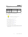
Manual
SCHUNK Motion Software
Version
1.00
1.01
1.15
1.16
1.17
1.18
1.20
1.22
1.23
1.24
1.25
1.26
1.30
1.40
1.41
Date
03.09.2007
29.10.2007
23.01.2008
31.01.2008
11.02.2008
18.03.2008
18.06.2008
29.07.2008
05.08.2008
02.09.2008
08.10.2008
19.11.2008
08.05.2009
10.12.2009
08.03.2010
Comment
Created
Revised
Added description SRV
Adapted to firmware V1.10
Corrected specification of SRV
Typos corrected
Adapted to firmware V1.20
Adapted to firmware V1.22
Corrected description of MD-SE parameters
Revised
Adapted to firmware V1.23
Adapted to firmware V1.24
Adapted to firmware V1.30
Adapted to firmware V1.40
Adapted to firmware V1.41
i
print date 8th March 2010
Contents
1 General
1.1 Electrical connection . . . . . . . . . . . . . . . . .
1.2 Indicators . . . . . . . . . . . . . . . . . . . . . . .
1.2.1 Factory settings . . . . . . . . . . . . . . .
1.2.2 Booting . . . . . . . . . . . . . . . . . . . .
1.3 Protocol . . . . . . . . . . . . . . . . . . . . . . . .
1.3.1 Data format . . . . . . . . . . . . . . . . . .
1.3.1.1 Floating point values . . . . . . .
1.3.1.2 Two’s complement . . . . . . . . .
1.3.2 Data frame . . . . . . . . . . . . . . . . . .
1.3.3 Special requirements with RS232 . . . . . .
1.3.4 Special requirements with CAN . . . . . . .
1.3.5 Special requirements with Profibus . . . . .
1.3.6 Fragmentation . . . . . . . . . . . . . . . .
1.3.6.1 Special requirements for Profibus .
1.4 Unit system . . . . . . . . . . . . . . . . . . . . . .
1.4.1 Float . . . . . . . . . . . . . . . . . . . . . .
1.4.2 Integer . . . . . . . . . . . . . . . . . . . . .
1.5 Users . . . . . . . . . . . . . . . . . . . . . . . . . .
1.5.1 User . . . . . . . . . . . . . . . . . . . . . .
1.5.2 Diag . . . . . . . . . . . . . . . . . . . . . .
1.5.3 Profi . . . . . . . . . . . . . . . . . . . . . .
1.5.4 Advanced . . . . . . . . . . . . . . . . . . .
1.5.5 Root . . . . . . . . . . . . . . . . . . . . . .
1.6 Pseudo absolute value transmitter . . . . . . . . .
1.6.1 Requirements . . . . . . . . . . . . . . . . .
1.6.2 Function . . . . . . . . . . . . . . . . . . . .
1.6.2.1 Resolver . . . . . . . . . . . . . .
1.6.2.2 Encoder with index . . . . . . . .
1.7 Standstill commutation . . . . . . . . . . . . . . .
1.7.1 Requirements . . . . . . . . . . . . . . . . .
1.7.2 Function . . . . . . . . . . . . . . . . . . . .
ii
.
.
.
.
.
.
.
.
.
.
.
.
.
.
.
.
.
.
.
.
.
.
.
.
.
.
.
.
.
.
.
.
.
.
.
.
.
.
.
.
.
.
.
.
.
.
.
.
.
.
.
.
.
.
.
.
.
.
.
.
.
.
.
.
.
.
.
.
.
.
.
.
.
.
.
.
.
.
.
.
.
.
.
.
.
.
.
.
.
.
.
.
.
.
.
.
.
.
.
.
.
.
.
.
.
.
.
.
.
.
.
.
.
.
.
.
.
.
.
.
.
.
.
.
.
.
.
.
.
.
.
.
.
.
.
.
.
.
.
.
.
.
.
.
.
.
.
.
.
.
.
.
.
.
.
.
.
.
.
.
.
.
.
.
.
.
.
.
.
.
.
.
.
.
.
.
.
.
.
.
.
.
.
.
.
.
.
.
.
.
.
.
.
.
.
.
.
.
.
.
.
.
.
.
.
.
.
.
.
.
.
.
.
.
.
.
.
.
.
.
.
.
.
.
.
.
.
.
.
.
.
.
.
.
.
.
.
.
.
.
.
.
.
.
.
.
.
.
1
1
2
3
3
4
4
5
5
6
7
8
9
11
11
12
12
13
14
14
14
15
15
15
15
15
16
16
16
17
17
17
Manual
SCHUNK Motion Software
2 Commands
2.1 Motion . . . . . . . . . . . . . . . . . . . . . . . . . . . . .
2.1.1 CMD REFERENCE (0x92) . . . . . . . . . . . . .
2.1.2 CMD REFERENCE HAND (0x97) . . . . . . . . .
2.1.3 MOVE POS (0xB0) . . . . . . . . . . . . . . . . .
2.1.4 MOVE POS REL (0xB8) . . . . . . . . . . . . . .
2.1.5 MOVE POS TIME (0xB1) . . . . . . . . . . . . .
2.1.6 MOVE POS TIME REL (0xB9) . . . . . . . . . .
2.1.7 MOVE POS LOOP (0xBA) . . . . . . . . . . . . .
2.1.8 MOVE POS TIME LOOP (0xBB) . . . . . . . . .
2.1.9 MOVE POS REL LOOP (0xBC) . . . . . . . . . .
2.1.10 MOVE POS TIME REL LOOP (0xBD) . . . . . .
2.1.11 MOVE CUR (0xB3) . . . . . . . . . . . . . . . . .
2.1.12 MOVE VEL (0xB5) . . . . . . . . . . . . . . . . .
2.1.13 MOVE GRIP (0xB7) . . . . . . . . . . . . . . . .
2.1.14 SET TARGET VEL (0xA0) . . . . . . . . . . . . .
2.1.15 SET TARGET ACC (0xA1) . . . . . . . . . . . .
2.1.16 SET TARGET JERK (0xA2) . . . . . . . . . . . .
2.1.17 SET TARGET CUR (0xA3) . . . . . . . . . . . .
2.1.18 SET TARGET TIME (0xA4) . . . . . . . . . . . .
2.1.19 CMD STOP (0x91) . . . . . . . . . . . . . . . . .
2.1.20 CMD EMERGENCY STOP (0x90) . . . . . . . .
2.2 Impulse messages . . . . . . . . . . . . . . . . . . . . . . .
2.2.1 CMD INFO (0x8A) . . . . . . . . . . . . . . . . .
2.2.1.1 SRV image processing sensor . . . . . . .
2.2.2 CMD MOVE BLOCKED (0x93) . . . . . . . . . .
2.2.3 CMD POS REACHED (0x94) . . . . . . . . . . .
2.2.4 CMD ERROR (0x88) . . . . . . . . . . . . . . . .
2.2.5 GET STATE (0x95) . . . . . . . . . . . . . . . . .
2.2.6 CMD TOGGLE IMPULSE MESSAGE (0xE7) . .
2.2.7 CAMAT SETTINGS CHANGED (0xF9) . . . . .
2.2.8 CAMAT RES MEASUREMENT BLOCK (0xFA)
2.3 Settings . . . . . . . . . . . . . . . . . . . . . . . . . . . .
2.3.1 SET CONFIG (0x81) . . . . . . . . . . . . . . . .
2.3.2 GET CONFIG (0x80) . . . . . . . . . . . . . . . .
2.4 Commands for internal programming . . . . . . . . . . . .
2.4.1 SET PHRASE (0xC0) . . . . . . . . . . . . . . . .
2.4.2 GET PHRASES (0xC2) . . . . . . . . . . . . . . .
2.4.3 PRG EXE (0xCF) . . . . . . . . . . . . . . . . . .
2.4.4 EXE PHRASE (0xC1) . . . . . . . . . . . . . . . .
2.4.5 EXE PHRASE0 (0xD0) . . . . . . . . . . . . . . .
2.4.6 EXE PHRASE1 (0xD1) . . . . . . . . . . . . . . .
2.4.7 EXE PHRASE2 (0xD2) . . . . . . . . . . . . . . .
2.4.8 EXE PHRASE3 (0xD3) . . . . . . . . . . . . . . .
2.4.9 EXE PHRASE4 (0xD4) . . . . . . . . . . . . . . .
2.4.10 EXE PHRASE5 (0xD5) . . . . . . . . . . . . . . .
iii
.
.
.
.
.
.
.
.
.
.
.
.
.
.
.
.
.
.
.
.
.
.
.
.
.
.
.
.
.
.
.
.
.
.
.
.
.
.
.
.
.
.
.
.
.
.
.
.
.
.
.
.
.
.
.
.
.
.
.
.
.
.
.
.
.
.
.
.
.
.
.
.
.
.
.
.
.
.
.
.
.
.
.
.
.
.
.
.
.
.
.
.
.
.
.
.
.
.
.
.
.
.
.
.
.
.
.
.
.
.
.
.
.
.
.
.
.
.
.
.
.
.
.
.
.
.
.
.
.
.
.
.
.
.
.
.
.
.
.
.
.
.
.
.
.
.
.
.
.
.
.
.
.
.
.
.
.
.
.
.
.
.
.
.
.
.
.
.
.
.
.
.
.
.
.
.
.
.
.
.
18
18
18
19
20
21
22
23
25
25
25
25
25
26
27
27
28
28
29
29
30
30
31
31
31
32
32
32
33
33
34
34
34
34
37
40
41
41
42
43
43
43
44
44
45
45
print date 8th March 2010
Manual
SCHUNK Motion Software
2.5
2.6
2.7
2.8
2.4.11
2.4.12
2.4.13
2.4.14
2.4.15
2.4.16
2.4.17
2.4.18
2.4.19
2.4.20
2.4.21
2.4.22
Other
2.5.1
EXE PHRASE6 (0xD6) . . . . . . . . . . . . . . .
EXE PHRASE7 (0xD7) . . . . . . . . . . . . . . .
EXE PHRASE8 (0xD8) . . . . . . . . . . . . . . .
EXE PHRASE9 (0xD9) . . . . . . . . . . . . . . .
EXE PHRASE10 (0xDA) . . . . . . . . . . . . . .
EXE PHRASE11 (0xDB) . . . . . . . . . . . . . .
EXE PHRASE12 (0xDC) . . . . . . . . . . . . . .
EXE PHRASE13 (0xDD) . . . . . . . . . . . . . .
EXE PHRASE14 (0xDE) . . . . . . . . . . . . . .
EXE PHRASE15 (0xDF) . . . . . . . . . . . . . .
PRG GOTO (0xC3) . . . . . . . . . . . . . . . . .
PRG WAIT (0xC4) . . . . . . . . . . . . . . . . .
commands . . . . . . . . . . . . . . . . . . . . . . .
GET STATE (0x95) . . . . . . . . . . . . . . . . .
2.5.1.1 Status response from SRV . . . . . . . .
2.5.2 CMD REBOOT (0xE0) . . . . . . . . . . . . . . .
2.5.3 CMD DIO (0xE1) . . . . . . . . . . . . . . . . . .
2.5.4 FLASH MODE (0xE2) . . . . . . . . . . . . . . .
2.5.5 CMD DISCONNECT (0xE6) . . . . . . . . . . . .
2.5.6 CHANGE USER (0xE3) . . . . . . . . . . . . . . .
2.5.7 CHECK MC PC COMMUNICATION (0xE4) . .
2.5.8 CHECK PC MC COMMUNICATION (0xE5) . .
SRV image processing sensor . . . . . . . . . . . . . . . .
2.6.1 CAMAT CHANGE PROGRAM (0xF8) . . . . . .
2.6.2 CAMAT SETTINGS CHANGED (0xF9) . . . . .
2.6.3 CAMAT RES MEASUREMENT BLOCK (0xFA)
2.6.4 CAMAT TRIGGER (0xFE) . . . . . . . . . . . . .
Fragmentation . . . . . . . . . . . . . . . . . . . . . . . .
2.7.1 FRAG ACK (0x87) . . . . . . . . . . . . . . . . .
2.7.2 FRAG START (0x84) . . . . . . . . . . . . . . . .
2.7.3 FRAG MIDDLE (0x85) . . . . . . . . . . . . . . .
2.7.4 FRAG END (0x86) . . . . . . . . . . . . . . . . .
Error messages . . . . . . . . . . . . . . . . . . . . . . . .
2.8.1 Error commands . . . . . . . . . . . . . . . . . . .
2.8.1.1 CMD ERROR (0x88) . . . . . . . . . . .
2.8.1.2 CMD WARNING (0x89) . . . . . . . . .
2.8.1.3 CMD INFO (0x8A) . . . . . . . . . . . .
2.8.1.4 CMD ACK (0x8B) . . . . . . . . . . . . .
2.8.1.5 GET DETAILED ERROR INFO (0x96)
2.8.2 Error codes . . . . . . . . . . . . . . . . . . . . . .
2.8.2.1 INFO BOOT (0x0001) . . . . . . . . . .
2.8.2.2 INFO NO FREE SPACE (0x02) . . . . .
2.8.2.3 INFO NO RIGHTS (0x03) . . . . . . . .
2.8.2.4 INFO UNKNOWN COMMAND (0x04) .
2.8.2.5 INFO FAILED (0x05) . . . . . . . . . . .
2.8.2.6 NOT REFERENCED (0x06) . . . . . . .
iv
.
.
.
.
.
.
.
.
.
.
.
.
.
.
.
.
.
.
.
.
.
.
.
.
.
.
.
.
.
.
.
.
.
.
.
.
.
.
.
.
.
.
.
.
.
.
.
.
.
.
.
.
.
.
.
.
.
.
.
.
.
.
.
.
.
.
.
.
.
.
.
.
.
.
.
.
.
.
.
.
.
.
.
.
.
.
.
.
.
.
.
.
.
.
.
.
.
.
.
.
.
.
.
.
.
.
.
.
.
.
.
.
.
.
.
.
.
.
.
.
.
.
.
.
.
.
.
.
.
.
.
.
.
.
.
.
.
.
.
.
.
.
.
.
.
.
.
.
.
.
.
.
.
.
.
.
.
.
.
.
.
.
.
.
.
.
.
.
.
.
.
.
.
.
.
.
.
.
.
.
.
.
.
.
46
46
46
47
47
48
48
49
49
50
50
51
51
51
54
54
54
55
55
56
56
58
59
60
61
61
62
62
62
63
63
63
63
64
64
64
65
65
65
66
66
66
67
67
67
67
print date 8th March 2010
Manual
SCHUNK Motion Software
2.8.2.7
2.8.2.8
2.8.2.9
2.8.2.10
2.8.2.11
2.8.2.12
2.8.2.13
2.8.2.14
2.8.2.15
2.8.2.16
2.8.2.17
2.8.2.18
2.8.2.19
2.8.2.20
2.8.2.21
2.8.2.22
2.8.2.23
2.8.2.24
2.8.2.25
2.8.2.26
2.8.2.27
2.8.2.28
2.8.2.29
2.8.2.30
2.8.2.31
2.8.2.32
2.8.2.33
2.8.2.34
2.8.2.35
2.8.2.36
2.8.2.37
2.8.2.38
2.8.2.39
2.8.2.40
2.8.2.41
2.8.2.42
2.8.2.43
2.8.2.44
2.8.2.45
2.8.2.46
2.8.2.47
2.8.2.48
2.8.2.49
INFO SEARCH SINE VECTOR (0x0007) .
INFO NO ERROR (0x0008) . . . . . . . . .
INFO COMMUNICATION ERROR (0x09) .
INFO TIMEOUT (0x10) . . . . . . . . . . .
INFO WRONG BAUDRATE (0x16) . . . .
INFO CHECKSUM (0x19) . . . . . . . . . .
INFO MESSAGE LENGTH (0x1D) . . . . .
INFO WRONG PARAMETER (0x1E) . . .
INFO PROGRAM END (0x1F) . . . . . . .
INFO TRIGGER (0x0040) . . . . . . . . . .
INFO READY (0x0041) . . . . . . . . . . . .
INFO GUI CONNECTED (0x0042) . . . . .
INFO GUI DISCONNECTED (0x0043) . . .
INFO PROGRAM CHANGED (0x44) . . . .
ERROR WRONG RAMP TYPE (0xC8) . .
ERROR CONFIG MEMORY (0xD2) . . . .
ERROR PROGRAM MEMORY (0xD3) . .
ERROR INVALID PHRASE (0xD4) . . . .
ERROR SOFT LOW (0xD5) . . . . . . . . .
ERROR SOFT HIGH (0xD6) . . . . . . . .
ERROR PRESSURE (0xD7) . . . . . . . . .
ERROR SERVICE (0xD8) . . . . . . . . . .
ERROR EMERGENCY STOP (0xD9) . . .
ERROR TOW (0xDA) . . . . . . . . . . . .
ERROR TOO FAST (0xE4) . . . . . . . . .
ERROR MATH (0xEC) . . . . . . . . . . . .
ERROR VPC3 (0xDB) . . . . . . . . . . . .
ERROR FRAGMENTATION (0xDC) . . . .
ERROR COMMUTATION (0xE4) . . . . . .
ERROR CURRENT (0xDE) . . . . . . . . .
ERROR I2T (0xDF) . . . . . . . . . . . . .
ERROR INITIALIZE (0xE0) . . . . . . . . .
ERROR INTERNAL (0xE1) . . . . . . . . .
ERROR HARD LOW (0xE2) . . . . . . . .
ERROR HARD HIGH (0xE3) . . . . . . . .
ERROR TEMP LOW (0x70) . . . . . . . . .
ERROR TEMP HIGH (0x71) . . . . . . . .
ERROR LOGIC LOW (0x72) . . . . . . . .
ERROR LOGIC HIGH (0x73) . . . . . . . .
ERROR MOTOR VOLTAGE LOW (0x74) .
ERROR MOTOR VOLTAGE HIGH (0x75)
ERROR CABLE BREAK (0x76) . . . . . .
ERROR MOTOR TEMP (0x78) . . . . . . .
v
.
.
.
.
.
.
.
.
.
.
.
.
.
.
.
.
.
.
.
.
.
.
.
.
.
.
.
.
.
.
.
.
.
.
.
.
.
.
.
.
.
.
.
.
.
.
.
.
.
.
.
.
.
.
.
.
.
.
.
.
.
.
.
.
.
.
.
.
.
.
.
.
.
.
.
.
.
.
.
.
.
.
.
.
.
.
67
68
68
68
68
68
69
69
69
69
69
70
70
70
70
71
71
71
71
71
71
72
72
72
72
72
72
72
73
73
73
73
73
73
74
74
74
74
74
74
75
75
75
print date 8th March 2010
Manual
SCHUNK Motion Software
3 Configuration data
3.1 General . . . . . . . . . . . . . . . . . . . . .
3.2 EEPROM . . . . . . . . . . . . . . . . . . . .
3.2.1 Motor . . . . . . . . . . . . . . . . . .
3.2.1.1 Serial Number . . . . . . . .
3.2.1.2 Voltage . . . . . . . . . . . .
3.2.1.3 Type . . . . . . . . . . . . .
3.2.1.4 I2T . . . . . . . . . . . . . .
3.2.1.5 Pole Pairs . . . . . . . . . . .
3.2.1.6 Ferrule Resistance . . . . . .
3.2.1.7 Inductance . . . . . . . . . .
3.2.1.8 Max. Current . . . . . . . .
3.2.1.9 Nom. Current . . . . . . . .
3.2.1.10 Max. Velocity . . . . . . . .
3.2.1.11 Max. Acceleration . . . . . .
3.2.1.12 Max. Jerk . . . . . . . . . .
3.2.1.13 Commutation Table . . . . .
3.2.1.14 Offset Phase A . . . . . . . .
3.2.1.15 Offset Phase B . . . . . . . .
3.2.2 Gear . . . . . . . . . . . . . . . . . . .
3.2.2.1 Serial Number . . . . . . . .
3.2.2.2 Gear Ratio 1 . . . . . . . . .
3.2.2.3 Gear Ratio 2 . . . . . . . . .
3.2.3 Reference . . . . . . . . . . . . . . . .
3.2.3.1 Type . . . . . . . . . . . . .
3.2.3.2 Max. Reference Current . . .
3.2.3.3 Velocity . . . . . . . . . . . .
3.2.3.4 Acceleration . . . . . . . . .
3.2.3.5 Offset . . . . . . . . . . . . .
3.2.3.6 Move Zero After Referencing
3.2.3.7 Timeout . . . . . . . . . . .
3.2.4 Controller . . . . . . . . . . . . . . . .
3.2.4.1 KR Current . . . . . . . . .
3.2.4.2 TN Current . . . . . . . . .
3.2.4.3 KR Speed . . . . . . . . . . .
3.2.4.4 TN Speed . . . . . . . . . . .
3.2.4.5 KR Position . . . . . . . . .
3.2.4.6 Delta Position . . . . . . . .
3.2.4.7 Structure . . . . . . . . . . .
3.2.5 Device . . . . . . . . . . . . . . . . . .
3.2.5.1 Serial Number . . . . . . . .
3.2.5.2 Unit System . . . . . . . . .
3.2.5.3 Communication Mode . . . .
3.2.5.4 Invert Motor . . . . . . . . .
3.2.5.5 Invert Position System . . .
3.2.5.6 Positioning Ramp Type . . .
vi
.
.
.
.
.
.
.
.
.
.
.
.
.
.
.
.
.
.
.
.
.
.
.
.
.
.
.
.
.
.
.
.
.
.
.
.
.
.
.
.
.
.
.
.
.
.
.
.
.
.
.
.
.
.
.
.
.
.
.
.
.
.
.
.
.
.
.
.
.
.
.
.
.
.
.
.
.
.
.
.
.
.
.
.
.
.
.
.
.
.
.
.
.
.
.
.
.
.
.
.
.
.
.
.
.
.
.
.
.
.
.
.
.
.
.
.
.
.
.
.
.
.
.
.
.
.
.
.
.
.
.
.
.
.
.
.
.
.
.
.
.
.
.
.
.
.
.
.
.
.
.
.
.
.
.
.
.
.
.
.
.
.
.
.
.
.
.
.
.
.
.
.
.
.
.
.
.
.
.
.
.
.
.
.
.
.
.
.
.
.
.
.
.
.
.
.
.
.
.
.
.
.
.
.
.
.
.
.
.
.
.
.
.
.
.
.
.
.
.
.
.
.
.
.
.
.
.
.
.
.
.
.
.
.
.
.
.
.
.
.
.
.
.
.
.
.
.
.
.
.
.
.
.
.
.
.
.
.
.
.
.
.
.
.
.
.
.
.
.
.
.
.
.
.
.
.
.
.
.
.
.
.
.
.
.
.
.
.
.
.
.
.
.
.
.
.
.
.
.
.
.
.
.
.
.
.
.
.
.
.
.
.
.
.
.
.
.
.
.
.
.
.
.
.
.
.
.
.
.
.
.
.
.
.
.
.
.
.
.
.
.
.
.
.
.
.
.
.
.
.
.
.
.
.
.
.
.
.
.
.
.
.
.
.
.
.
.
.
.
.
.
.
.
.
.
.
.
.
.
.
.
.
.
.
.
.
.
.
.
.
.
.
.
.
.
.
.
.
.
.
.
.
.
.
.
.
.
.
.
.
.
.
.
.
.
.
.
.
.
.
.
.
.
.
.
.
.
.
.
.
.
.
.
.
.
.
.
.
.
.
.
.
.
.
.
.
.
.
.
.
.
.
.
.
.
.
.
.
.
.
.
.
.
.
.
.
.
.
.
.
.
.
.
.
.
.
.
.
.
.
.
.
.
.
.
.
.
.
.
.
.
.
.
.
.
76
76
76
77
77
77
77
78
78
78
78
79
79
80
80
80
80
80
81
81
81
81
81
81
81
83
84
84
84
84
84
84
84
85
85
85
85
85
85
86
86
86
87
87
88
88
print date 8th March 2010
Manual
SCHUNK Motion Software
3.2.6
3.2.7
3.2.8
3.2.5.7 Start Program On Boot . . .
3.2.5.8 Endless . . . . . . . . . . . .
3.2.5.9 Digital In Usage . . . . . . .
3.2.5.10 Digital Out Usage . . . . . .
3.2.5.11 Analog OUT Usage . . . . .
3.2.5.12 Internal Switch Usage . . . .
3.2.5.13 ID . . . . . . . . . . . . . . .
3.2.5.14 Group . . . . . . . . . . . . .
3.2.5.15 RS232 Baud Rate . . . . . .
3.2.5.16 CAN Baud Rate . . . . . . .
3.2.5.17 Min. Position . . . . . . . .
3.2.5.18 Max. Position . . . . . . . .
3.2.5.19 Tow Error . . . . . . . . . .
3.2.5.20 Min. Temperature . . . . . .
3.2.5.21 Max. Temperature . . . . . .
Positioning . . . . . . . . . . . . . . .
3.2.6.1 Serial Number . . . . . . . .
3.2.6.2 Type . . . . . . . . . . . . .
3.2.6.3 Mount . . . . . . . . . . . .
3.2.6.4 Parameter 1 . . . . . . . . .
3.2.6.5 Parameter 2 . . . . . . . . .
3.2.6.6 Offset . . . . . . . . . . . . .
3.2.6.7 Motion Threshold . . . . . .
3.2.6.8 ADC Offset . . . . . . . . . .
Brake . . . . . . . . . . . . . . . . . .
3.2.7.1 Serial Number . . . . . . . .
3.2.7.2 Type . . . . . . . . . . . . .
3.2.7.3 Brake Usage . . . . . . . . .
3.2.7.4 Timeout . . . . . . . . . . .
SRU . . . . . . . . . . . . . . . . . . .
3.2.8.1 Type . . . . . . . . . . . . .
3.2.8.2 Service Notification . . . . .
3.2.8.3 Brake Point Coefficient . . .
3.2.8.4 Brake Point S2X . . . . . . .
3.2.8.5 KR Valve Undershoot . . . .
3.2.8.6 Throw Back . . . . . . . . .
3.2.8.7 Delta Position Valve Off . .
3.2.8.8 Max. Brake Point Difference
3.2.8.9 Hit Back Overshoot . . . . .
3.2.8.10 Turn Count Factor . . . . . .
3.2.8.11 Manual Mode Factor . . . .
vii
.
.
.
.
.
.
.
.
.
.
.
.
.
.
.
.
.
.
.
.
.
.
.
.
.
.
.
.
.
.
.
.
.
.
.
.
.
.
.
.
.
.
.
.
.
.
.
.
.
.
.
.
.
.
.
.
.
.
.
.
.
.
.
.
.
.
.
.
.
.
.
.
.
.
.
.
.
.
.
.
.
.
.
.
.
.
.
.
.
.
.
.
.
.
.
.
.
.
.
.
.
.
.
.
.
.
.
.
.
.
.
.
.
.
.
.
.
.
.
.
.
.
.
.
.
.
.
.
.
.
.
.
.
.
.
.
.
.
.
.
.
.
.
.
.
.
.
.
.
.
.
.
.
.
.
.
.
.
.
.
.
.
.
.
.
.
.
.
.
.
.
.
.
.
.
.
.
.
.
.
.
.
.
.
.
.
.
.
.
.
.
.
.
.
.
.
.
.
.
.
.
.
.
.
.
.
.
.
.
.
.
.
.
.
.
.
.
.
.
.
.
.
.
.
.
.
.
.
.
.
.
.
.
.
.
.
.
.
.
.
.
.
.
.
.
.
.
.
.
.
.
.
.
.
.
.
.
.
.
.
.
.
.
.
.
.
.
.
.
.
.
.
.
.
.
.
.
.
.
.
.
.
.
.
.
.
.
.
.
.
.
.
.
.
.
.
.
.
.
.
.
.
.
.
.
.
.
.
.
.
.
.
.
.
.
.
.
.
.
.
.
.
.
.
.
.
.
.
.
.
.
.
.
.
.
.
.
.
.
.
.
.
.
.
.
.
.
.
.
.
.
.
.
.
.
.
.
.
.
.
.
.
.
.
.
.
.
.
.
.
.
.
.
.
.
.
.
.
.
.
.
.
.
.
.
.
.
.
.
.
.
.
.
.
.
.
.
.
.
.
.
.
.
.
.
.
.
.
.
.
. 89
. 90
. 90
. 91
. 92
. 93
. 93
. 93
. 93
. 93
. 94
. 94
. 94
. 94
. 94
. 94
. 94
. 95
. 95
. 96
. 96
. 96
. 97
. 97
. 97
. 97
. 97
. 97
. 98
. 98
. 98
. 98
. 98
. 98
. 99
. 99
. 99
. 99
. 99
. 99
. 100
print date 8th March 2010
Manual
SCHUNK Motion Software
4 MCDemo
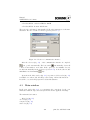
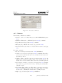
4.1 Requirements . . . . . . . . . . . . . . . . . . . . . . . . . . .
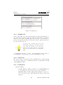
4.2 First steps . . . . . . . . . . . . . . . . . . . . . . . . . . . . .
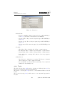
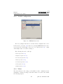
4.3 Main window . . . . . . . . . . . . . . . . . . . . . . . . . . .
4.3.1 Toolbar . . . . . . . . . . . . . . . . . . . . . . . . . .
4.3.2 Menu . . . . . . . . . . . . . . . . . . . . . . . . . . .
4.3.3 Output tabs . . . . . . . . . . . . . . . . . . . . . . . .
4.3.4 Status bar . . . . . . . . . . . . . . . . . . . . . . . . .
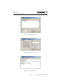
4.3.5 Preferences . . . . . . . . . . . . . . . . . . . . . . . .
4.3.6 Tools . . . . . . . . . . . . . . . . . . . . . . . . . . .
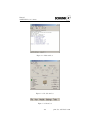
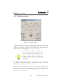
4.4 Module window . . . . . . . . . . . . . . . . . . . . . . . . . .
4.4.1 Buttons . . . . . . . . . . . . . . . . . . . . . . . . . .
4.4.2 Module configuration . . . . . . . . . . . . . . . . . .
4.4.3 Menu . . . . . . . . . . . . . . . . . . . . . . . . . . .
4.4.4 Manual Referencing . . . . . . . . . . . . . . . . . . .
4.4.5 Setup Wizard . . . . . . . . . . . . . . . . . . . . . . .
4.5 Tips . . . . . . . . . . . . . . . . . . . . . . . . . . . . . . . .
4.5.1 Supported languages . . . . . . . . . . . . . . . . . . .
4.5.2 Driver Vector CAN . . . . . . . . . . . . . . . . . . . .
4.5.3 Driver Peak CAN . . . . . . . . . . . . . . . . . . . .
4.5.4 Driver Softing CAN . . . . . . . . . . . . . . . . . . .
4.5.5 Interface ESD CAN . . . . . . . . . . . . . . . . . . .
4.5.6 Interface Siemens Profibus . . . . . . . . . . . . . . . .
4.5.7 Automatically display the module status . . . . . . . .
4.5.8 Open communications interface by starting MCDemo
4.5.9 Data throughput with CAN . . . . . . . . . . . . . . .
4.5.10 Configured modules under Profibus . . . . . . . . . . .
4.5.11 Frequent timeouts with RS232 communications . . . .
4.5.12 Modifying individual EEPROM parameters . . . . . .
4.5.13 Do not maximize the main window . . . . . . . . . . .
4.5.14 Communication mode Auto” . . . . . . . . . . . . . .
”
4.5.15 Initialize modules manually . . . . . . . . . . . . . . .
.
.
.
.
.
.
.
.
.
.
.
.
.
.
.
.
.
.
.
.
.
.
.
.
.
.
.
.
.
.
.
.
.
.
.
.
.
.
.
.
.
.
.
.
.
.
.
.
.
.
.
.
.
.
.
.
.
.
.
.
.
.
101
101
101
102
104
104
106
106
106
107
109
110
111
111
116
117
117
117
117
117
117
118
118
118
118
118
119
119
119
119
119
120
5 Troubleshooting
5.1 Module . . . . . . . . . . . . . . . . . . . . . . . . . . . . . . .
5.1.1 Connection description for the module . . . . . . . . . .
5.1.2 Module fails to reference from some positions . . . . . .
5.2 Protocol . . . . . . . . . . . . . . . . . . . . . . . . . . . . . . .
5.2.1 Fragmentation not possible . . . . . . . . . . . . . . . .
5.3 RS232 . . . . . . . . . . . . . . . . . . . . . . . . . . . . . . . .
5.3.1 Data collision occurred . . . . . . . . . . . . . . . . . . .
5.3.2 I encounter problems when connecting several modules .
5.3.3 Which RS232 baud rates are supported by the module?
5.4 CAN . . . . . . . . . . . . . . . . . . . . . . . . . . . . . . . . .
5.4.1 Which CAN baud rates are supported by the module? .
5.5 Profibus . . . . . . . . . . . . . . . . . . . . . . . . . . . . . . .
.
.
.
.
.
.
.
.
.
.
.
.
121
121
121
121
121
121
121
121
122
122
122
122
122
viii
print date 8th March 2010
Manual
SCHUNK Motion Software
5.5.1
5.5.2
Does the system support SSA (Set-Slave-Address)? . . . . 122
Data transfer is not consistent . . . . . . . . . . . . . . . 122
6 Appendix
6.1 Examples . . . . . . . . . . . . . . . . . . . . . . . . . . . . . .
6.1.1 RS232 . . . . . . . . . . . . . . . . . . . . . . . . . . . .
6.1.1.1 Referencing . . . . . . . . . . . . . . . . . . . .
6.1.1.2 MOVE POS 10 [mm] . . . . . . . . . . . . . .
6.1.1.3 GET STATE 1 [s] . . . . . . . . . . . . . . . .
6.1.1.4 Troubleshooting . . . . . . . . . . . . . . . . .
6.1.1.5 CHECK MC PC COMMUNICATION (Float)
6.1.1.6 CHECK PC MC COMMUNICATION . . . .
6.1.2 CAN . . . . . . . . . . . . . . . . . . . . . . . . . . . . .
6.1.2.1 Referencing . . . . . . . . . . . . . . . . . . . .
6.1.2.2 MOVE POS 10 [mm] . . . . . . . . . . . . . .
6.1.2.3 GET STATE 1 [s] . . . . . . . . . . . . . . . .
6.1.2.4 Troubleshooting . . . . . . . . . . . . . . . . .
6.1.2.5 CHECK MC PC COMMUNICATION (Float)
6.1.2.6 CHECK PC MC COMMUNICATION . . . .
6.1.3 Profibus . . . . . . . . . . . . . . . . . . . . . . . . . . .
6.1.3.1 Referencing . . . . . . . . . . . . . . . . . . . .
6.1.3.2 MOVE POS 10 [mm] . . . . . . . . . . . . . .
6.1.3.3 GET STATE 1 [s] . . . . . . . . . . . . . . . .
6.1.3.4 Troubleshooting . . . . . . . . . . . . . . . . .
6.1.3.5 CHECK MC PC COMMUNICATION (Float)
6.1.3.6 CHECK PC MC COMMUNICATION . . . .
6.2 CRC16 calculation for RS232 . . . . . . . . . . . . . . . . . . .
6.3 Commands . . . . . . . . . . . . . . . . . . . . . . . . . . . . .
6.4 Info and error codes . . . . . . . . . . . . . . . . . . . . . . . .
6.5 Tested hardware . . . . . . . . . . . . . . . . . . . . . . . . . .
7 Contact
.
.
.
.
.
.
.
.
.
.
.
.
.
.
.
.
.
.
.
.
.
.
.
.
.
.
123
123
123
123
123
124
124
124
125
125
125
125
126
126
126
127
127
127
128
128
129
129
130
131
133
136
138
139
ix
print date 8th March 2010
Chapter 1
General
1.1
Electrical connection
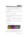
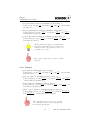
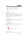
The module is equipped with separate input terminals for the motor voltage and
the logic control voltage (24V DC). We recommend connecting the terminals to
two separate power supplies so that the logic control continues to operate even
if there is an overload at the motor, ensuring that the motor status is known at
all times. For modules with a motor voltage > 24V DC, the connections must
be separated as the logic control voltage must be between 18 and 32V DC.
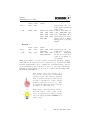
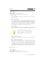
Risk of permanent damage to the electronics! When using separate power supplies,
provide for potential equalization between the
two supply systems (connect earth conductors).
With separate power supply lines to the logic
control and the motor, the control can switch
off the power to the motor by means of a relay,
while the module remains activated through the
bus system.
The motor must be supplied through a power supply unit, which provides
the current required by the respective module. All cables must have the necessary cross-section.
The voltage drop along the cable can be calculated with the following formula:
Δ𝑈 = 2∗𝐼∗𝑙
𝛾∗𝐴 where :
I: Current consumption of motor
l: Length of line
𝛾 : Electrical conductivity
𝑚
𝐶𝑢 : 𝛾 = 56 Ω∗𝑚𝑚
2
1
Manual
SCHUNK Motion Software
𝑚
𝐴𝑙 : 𝛾 = 35 Ω∗𝑚𝑚
2
A: Conductor cross-section
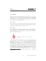
The upper description does not apply for the
SRV image processing sensor, for which the
specific user’s manual is to be consulted. The
present document describes, in conjunction
with the SRV, only the communication with
the SCHUNK Motion Protocol via the serial
RS232 connection, see SRV image processing
”
sensor” (section 2.6) .
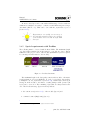
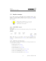
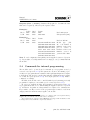
1.2
Indicators
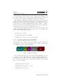
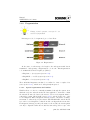
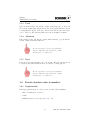
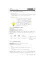
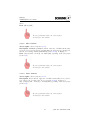
All modules are equipped with 3 LED indicators.
In some models, these indicators are not led
to the outside of the housing and are thus only
visible when the module is opened.
The green LED (POW LED) indicates the motor voltage status. If the LED
is not on or only flickers faintly, check the motor supply voltage (24 -48 V DC).
The two other LEDs (green and red) indicate the status of the logical circuits:
2
print date 8th March 2010
Manual
SCHUNK Motion Software
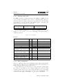
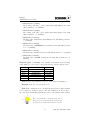
LED1 (green)
continuously on
LED2 (red)
continuously on
continuously on
briefly on, then off
on
flashing
briefly on, then off
off
flickering
off
off
off
off
on / flashing
off / on
on / off
flickering
flashing / flickering
fast off / on
fast on / off
1.2.1
Interpretation
Module is in flash mode (section 2.5.4)
or no bus system active.
New firmware is programming
Module booted.
Module is ready for operation and bus
system is active.
Data is being exchanged.
No logic control voltage. If both LEDs
were briefly on (booting phase), the
connected bus system could not be initialized. Check bus cable. Is the master
active?
An error (section 2.8.1.1) occurred in
the module.
Profibus is active, but not yet in ”Data
Exchange” mode, or automatic interface detection running.
Data is exchanged on the ”main interface”, while the diagnostic interface
(section 1.5.2) is active, so that data is
also exchanged through this interface.
Firmware status undefined (should
never occur).
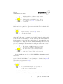
Factory settings
If the module is reset to the factory settings, the following values in the EEPROM are overwritten and reset:
∙ ID
reset to default ID. (gripper: 12)
∙ CAN baud rate
reset to default CAN baud rate (500 [kBaud]).
∙ RS232 baud rate
reset to default RS232 baud rate (9600 [Baud]).
∙ Communication system
reset to default communication system (RS232).
1.2.2
Booting
After successful booting of the module, a number of parameters for movements
are already set to the start values. This allows the operator to start module
3
print date 8th March 2010
Manual
SCHUNK Motion Software
operation without the need to first set all parameters. The following parameters
are automatically set during booting:
∙ TargetVel” (section 2.1.14)
”
in [%] of maximum value (section 3.2.1.10) . -> 10%
∙ TargetAcc” (section 2.1.15)
”
in [%] of maximum value (section 3.2.1.11) . -> 10%
∙ TargetJerk” (section 2.1.16)
”
in [%] of maximum value (section 3.2.1.12) . -> 50%
∙ TargetCurrent” (section 2.1.17)
”
Nominal current (section 3.2.1.9) .
∙ impulse messages (section 2.2.6) activated.
∙ User is set to ”User”.
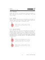
The upper description does not apply for the
SRV image processing sensor, for which the
specific user’s manual is to be consulted. The
present document describes, in conjunction
with the SRV, only the communication with
the SCHUNK Motion Protocol via the serial
RS232 connection, see SRV image processing
”
sensor” (section 2.6) .
1.3
1.3.1
Protocol
Data format
Data is sent by the modules in Intel format (”little Endian”) and interpreted in
this format upon reception.
If there is any uncertainty about the endianness when setting up the own driver, use
CHECK MC PC COMMUNICATION” (sec”
tion 2.5.7) , or CHECK PC MC COMMU”
NICATION” (section 2.5.8) with predefined
test data.
4
print date 8th March 2010
Manual
SCHUNK Motion Software
1.3.1.1
Floating point values
The IEEE Standard for Binary Floating-Point Arithmetic” (IEEE 754) was
”
developed in the early 1980s in order to cater for consistent floating point representation in different computer architectures. If parameters are sent as floating
point numbers to/from the modules, this standard applies. A floating point
number is thereby represented as a 32-bit value.
Plus/minus sign bit
1 bit (bit 32)
s
Exponent
8 bit (bit 23.. bit 30)
e
Mantissa (standardized)
23 bit (bit 1.. bit 22)
f
As the mantissa is always set to ”1”, only the decimals are stored, as the
leading ”1” does not need to be recorded. A floating point value can thus be
calculated as follows:
(−1)𝑠 ∗ 2𝑒−127 ∗ (1.𝑓 )𝑏𝑖𝑛
Examples:
7/4
-34.432175
-959818
+0
-0
2−126 , 𝑜𝑟1.175 ∗ 10−38
Smallest positive number
(2 − 2−23 ) 2127 , 𝑜𝑟3.403 ∗ 1038
Largest positive number
infinite
NaN
Macheps 2−23 , 𝑜𝑑𝑒𝑟1.192 ∗ 10−7
Smallest distinct number
2−128
1.3.1.2
Sign
1 bit
0
1
1
0
1
Exponent
8 bit
01111111
10000100
10010010
00000000
00000000
Mantissa
23 bit
11000000000000000000000
00010011011101010001100
11010100101010010100000
00000000000000000000000
00000000000000000000000
0
00000001
00000000000000000000000
0
0
0
11111110
11111111
11111111
11111111111111111111111
11111111111111111111111
not all 0” or 1”
”
”
0
0
01101000
00000000
00000000000000000000000
01000000000000000000000
Two’s complement
The two’s complement offers a way of displaying negative numbers in the binary
system. In the module, the two’s complement is used for the representation of
negative integers. (Integer system (section 1.4) ).
Positive numbers are represented as two’s components with a leading 0 (sign
bit). They are not further encoded. Negative numbers are represented with
a leading 1 (sign bit) and encoded as follows: all digits of the corresponding
positive figure are negated. The value 1 is added to the result. Example of the
conversion of the negative decimal figure −4dec in a two’s complement:
5
print date 8th March 2010
Manual
SCHUNK Motion Software
1. Ignore sign and convert to binary system: 4dec = 00000100bin = 0𝑥04hex
2. Invert, as the value is negative: 11111011bin = 0𝑥𝐹 𝐵hex
3. Add 1, as figure is negative: 11111011bin + 00000001bin = 11111100bin =
0𝑥𝐹 𝐶hex = −4dec
Or more mathematically:
Is x is a negative number, x is represented as a two’s complement (𝑥z ) with n
digits as follows:
𝑥𝑧 = 2𝑛 − ∣𝑥∣
This means that the following equation applies:
𝑥𝑧 + ∣𝑥∣ = 2𝑛
As the module, when set to Integer system” (section 1.4) always works
”
with Int32 (4 bytes), the byte sequences of negative numbers x (e.g. -112) can
be calculated easily as follows:
𝑦 = 4294967296𝑑𝑒𝑐 − ∣𝑥∣ ⇒ 𝑦 = 4294967296𝑑𝑒𝑐 − 112𝑑𝑒𝑐 = 4294967184𝑑𝑒𝑐
𝑦 = 0𝑥100000000ℎ𝑒𝑥 −∣𝑥∣ ⇒ 𝑦 = 0𝑥100000000ℎ𝑒𝑥 −0𝑥70ℎ𝑒𝑥 = 0𝑥𝐹 𝐹 𝐹 𝐹 𝐹 𝐹 90ℎ𝑒𝑥
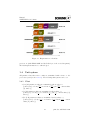
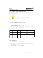
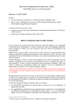
1.3.2
Data frame
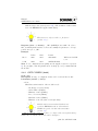
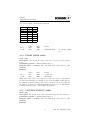
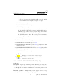
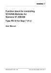
The data frame of the motion protocol always contains the following elements.
∙ D-Len (1 byte)
∙ Command Code (1 byte)
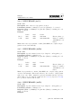
Figure 1.1: Data frame
D-Len (data length) indicates the number of subsequent useful data items
including the command byte. The data frame consists of one byte, so that a
motion protocol message can consist of maximum 255 data bytes.
6
print date 8th March 2010
Manual
SCHUNK Motion Software
The D-Len byte is always followed by the command code consisting of one
byte. The command code is followed by the required parameters, if any. If
necessary, a ”super command” is complemented with a ”sub command”.
All commands are immediately acknowledged with a response (acknowledge)
when they are received by the module. This response also conforms to the above
described data frame format (D-Len, command code, parameters). After the
request has been processed successfully, D-Len is always > ”0x02” or = ”0x01”.
If the request was not successful, D-Len is always ”0x02”. The following bytes
indicate the cause of the unsuccessful request (section 2.8.2) .
These modules also issue messages if there was not previous request. The
format of these ”impulse messages” also conform to the above data frame. The
following events trigger impulse messages.
∙ A serious error occurred.
∙ A motion was completed successfully.
∙ Regular status messages (section 2.2) , if activated.
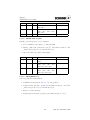
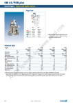
1.3.3
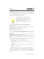
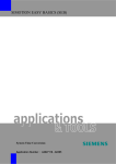
Special requirements with RS232
As the RS232 was not intended as a bus system when devised, a number of
elements must be added to the data frame in order to enable several modules
to communicate through a single serial interface.
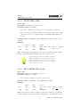
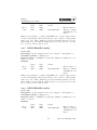
Figure 1.2: RS232 data frame
The data frame is followed by two bytes (group/ID) indicating the module
to be targeted or the module that sent the response. Only the first three bits of
the first byte are used. The second byte constitutes a unique module ID. =>
up to 255 different modules can be addressed. The first three bits of the first
byte are encoded as follows:
∙ 0x03 Error signal from module
∙ 0x05 Message from master to a module
∙ 0x07 Response from module
7
print date 8th March 2010
Manual
SCHUNK Motion Software
The other statuses are not used.
The method of uniquely identifying a module
with 11 bits has been adopted for the CAN protocol.
In order to ensure reliable data transfer with RS232, a checksum (CRC16
=> 2 bytes) of all data including group/ID, D-Len and Cmd is attached at the
end of the data frame. An algorithm for the calculation of a CRC 16 checksum
is included in the appendix (section 6.2) . As RS232 is not a real bus system but
can be wired like a bus system, there is a risk of data collision if several modules
are simultaneously sending data to the master. Such collisions can however
be easily detected and the necessary measures can be taken in order to clearly
identify the status of all modules. If a large number of modules are operated on
one ”branch”, it might be necessary to disable (section 2.2.6) impulse message
(section 2.2) .
1.3.4
Special requirements with CAN
CAN is a message-oriented bus system. In addition to the data frame, it therefore requires identifiers that uniquely identify each message The modules support
the standard 11-bit identifier. The low 8 bits are thereby used for the unique
module ID => up to 255 different modules can be addressed. The remaining
unassigned 3 bits are encoded as follows:
∙ 0x03 Error signal from module
∙ 0x05 Message from master to a module
∙ 0x07 Response from module
The other statuses are not used.
∙ A message sent to the module thus contains the following identifier: 0x5XX.
(XX module address in hex format).
∙ A message sent by the module contains the following identifier: 0x7XX.
(XX module address in hex format)
∙ In the event of an error, the messages from the module to the master are
equipped with the identifier: 0x3XX. (XX module address in hex format)
8
print date 8th March 2010
Manual
SCHUNK Motion Software
At most 8 data bytes can be sent with a CAN message. Under certain circumstances, it might be necessary to combine several CAN messages in a longer
data frame (D-Len > 7). This can be done with the fragmentation protocol
(section 1.3.6) .
Fragmentation is normally not necessary, as
all commands required for the proper operation
of the modules can be encoded in single CAN
messages.
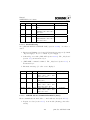
1.3.5
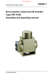
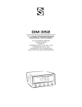
Special requirements with Profibus
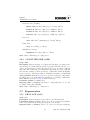
The following must be observed with Profibus PDV0: The maximum length
of a data packet transferred from the master to a module is 8 bytes. This is
sufficient for the proper control of the module (maximum 7 bytes are required
for a message from the master to the module).
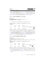
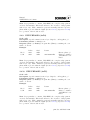
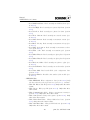
Figure 1.3: Profibus data frame
The maximum length of the data packet sent from the module to the master
(reply) is limited to 16 bytes (GSD file). To send / receive larger data packets,
you might need to use fragmentation (section 1.3.6) . With 16 bytes, the longest
message from the module to the master occurring during normal operation (14
bytes) can be catered for. The remaining 2 bytes that are always found at the
end of the Profibus message (bytes 14 and 15) indicate
1. the current state (section 2.5.1) of the module (byte 14) and
2. command counter (MsgCount) (byte 15)
1
1 In
fragmented messages, these two bytes are used for data.
9
print date 8th March 2010
Manual
SCHUNK Motion Software
Only the high 8 bits of the status word are written. The error code is omitted. For errors,
Profibus offers extended diagnostics. The error code (section 2.8.1.1) is included in the
output data.
For messages sent by the master to the module, a response is sent and the
MsgCount is incremented by 1. This ensures that each request is acknowledged,
event if there are impulse messages.
Impulse messages (section 2.2)
crease the MsgCount!
do not in-
If the position in which the module is currently found is to be achieved,
the module replies with ”command received” followed instantly with ”position
reached” in the next Profibus cycle. As the control system connected with the
Profibus might not query data with each Profibus cycle, the acknowledge messages might be lost during the motion command. The MsgCount ensures that
an acknowledgment of the request is received. The status byte (section 2.5.1)
(byte 14) contains up-to-date information regarding the status of the module.
The last bit of the MsgCount can be evaluated
as a toggle bit (module to master messages.).
For data transfer from the master to the module, the not yet used byte 8 can be used as the
toggle byte, or bit 63 can be used as toggle bit.
Groups are fully supported by the SYNC, FREEZE mechanism implemented
in Profibus.
Addresses can be changed at any time with the ”Set Slave Address” (SAP 55)
service. ”Real No Add Change” is stored in the group byte (section 3.2.5.14)
gespeichert. A set ”Real No Add Change” (0xFF) can thus be deleted by reconfiguring the group byte (section 2.3.1) .
If consistent data transfer is not possible, the
module can be operated as follows:
1. Use SYNC, UNSYNC mechanism.
2. Set D-Len to ”0”. Fill up all data and set D-Len when all data is added.
10
print date 8th March 2010
Manual
SCHUNK Motion Software
1.3.6
Fragmentation
During normal operation, messages do not
need to be fragmented!
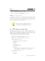
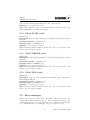
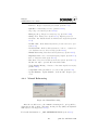
If messages need to be fragmented, proceed as follows:
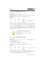
Figure 1.4: Fragmentation
At the start of each message, the length of the subsequent useful data is
transmitted. Subsequently, a fragmentation code is sent. This fragmentation
code is not included in the length byte (D-Len).
∙ FragStart -> first fragment (section 2.7.2) .
∙ FragMiddle -> middle fragment (section 2.7.3) .
∙ FragEnd -> last fragment (section 2.7.4) .
These individual fragments can thus be recombined to form a complete data
frame (section 1.3.2) , which can be subsequently interpreted.
1.3.6.1
Special requirements for Profibus
With Profibus, a ”token” is constantly transmitted through the system, from
which the respective subscribers take the data applicable to them and to which
the subscribers write the data for the master, each received fragment must be
acknowledged with FRAG ACK” (section 2.7.1) and the D-Len byte of the
”
received fragment. When a fragmented message is sent to the master, each fragment must be acknowledged by the master with ”FRAG ACK” and the D-Len
byte of the received fragment, so that the module can dispatch the next module.
If a fragmented message is sent by the master to the module, the next fragment
can only be dispatched when the module has acknowledged the receipt of the
11
print date 8th March 2010
Manual
SCHUNK Motion Software
Figure 1.5: Fragmentation for Profibus
previous one (with ”FRAG ACK” and the D-Len byte of the received fragment).
The last fragment must not be acknowledged.
1.4
Unit system
All parameter data that refer to units are transmitted with reference to the
preset unit system (section 3.2.5.2) . The following unit systems can be set:
1.4.1
Float
∙ [𝑚𝑚] all parameters values are transmitted as float values =>
𝑚𝑚
𝑚𝑚
position [𝑚𝑚], velocity [ 𝑚𝑚
𝑠 ], acceleration [ 𝑠2 ], jerk [ 𝑠3 ] , current values
[𝐴], times [𝑠]
∙ [𝑚] all parameters values are transmitted as float values =>
𝑚
𝑚
position [𝑚], velocity [ 𝑚
𝑠 ], acceleration [ 𝑠2 ], jerk [ 𝑠3 ] , current values [𝐴],
times [𝑠]
∙ [𝐼𝑛𝑐ℎ] all parameters values are transmitted as float values =>
𝐼𝑛𝑐ℎ
𝐼𝑛𝑐ℎ
position [𝐼𝑛𝑐ℎ], velocity [ 𝐼𝑛𝑐ℎ
𝑠 ], acceleration [ 𝑠2 ], Ruck [ 𝑠3 ] , current
values [𝐴], times [𝑠]
12
print date 8th March 2010
Manual
SCHUNK Motion Software
∙ [𝑟𝑎𝑑] all parameters values are transmitted as float values =>
𝑟𝑎𝑑
𝑟𝑎𝑑
position [𝑟𝑎𝑑], velocity [ 𝑟𝑎𝑑
𝑠 ], acceleration [ 𝑠2 ], jerk [ 𝑠3 ] , current values
[𝐴], times [𝑠]
∙ [𝐷𝑒𝑔𝑟𝑒𝑒] all parameters values are transmitted as float values =>
position [𝐷𝑒𝑔𝑟𝑒𝑒], velocity [ 𝐷𝑒𝑔𝑟𝑒𝑒
], acceleration [ 𝐷𝑒𝑔𝑟𝑒𝑒
], jerk [ 𝐷𝑒𝑔𝑟𝑒𝑒
],
𝑠
𝑠2
𝑠3
current values [𝐴], times [𝑠]
∙ [𝑖𝑛𝑡𝑒𝑟𝑛] all parameters values are transmitted as float values =>
𝑖𝑛𝑡𝑒𝑟𝑛
], acceleration [ 𝑖𝑛𝑡𝑒𝑟𝑛
position [𝑖𝑛𝑡𝑒𝑟𝑛], velocity [ 𝑖𝑛𝑡𝑒𝑟𝑛
𝑠
𝑠2 ], jerk [ 𝑠3 ] , current values [𝐴], times [𝑠]
All data in this unit system is calculated internally with a system that is based on the motor
revolutions. The gear transmission ratios are
not taken into account.
This system should only be used for testing
purposes!
1.4.2
Integer
∙ [𝜇𝑚] values are transmitted as integer values =>
𝜇𝑚
𝜇𝑚
position [𝜇𝑚], velocity [ 𝜇𝑚
𝑠 ], acceleration [ 𝑠2 ], jerk [ 𝑠3 ] , current values
[𝑚𝐴], times [𝑚𝑠]
∙ [𝜇𝐷𝑒𝑔𝑟𝑒𝑒] values are transmitted as integer values =>
position [𝜇𝐷𝑒𝑔𝑟𝑒𝑒], velocity [ 𝜇𝐷𝑒𝑔𝑟𝑒𝑒
], acceleration [ 𝜇𝐷𝑒𝑔𝑟𝑒𝑒
], jerk [ 𝜇𝐷𝑒𝑔𝑟𝑒𝑒
]
𝑠
𝑠2
𝑠3
, current values [𝑚𝐴], times [𝑚𝑠]
∙ [𝜇𝐼𝑛𝑐ℎ] values are transmitted as integer values =>
𝜇𝐼𝑛𝑐ℎ
𝜇𝐼𝑛𝑐ℎ
position [𝜇𝐼𝑛𝑐ℎ], velocity [ 𝜇𝐼𝑛𝑐ℎ
𝑠 ], acceleration [ 𝑠2 ], jerk [ 𝑠3 ] , current values [𝑚𝐴], times [𝑚𝑠]
∙ [𝑀 𝑖𝑙𝑙𝑖 − 𝑑𝑒𝑔𝑟𝑒𝑒] values are transmitted as integer values =>
position [𝑀 𝑖𝑙𝑙𝑖−𝑑𝑒𝑔𝑟𝑒𝑒], velocity [ 𝑀 𝑖𝑙𝑙𝑖−𝑑𝑒𝑔𝑟𝑒𝑒
], acceleration [ 𝑀 𝑖𝑙𝑙𝑖−𝑑𝑒𝑔𝑟𝑒𝑒
],
𝑠
𝑠2
𝑀 𝑖𝑙𝑙𝑖−𝑑𝑒𝑔𝑟𝑒𝑒
jerk [
]
,
current
values
[𝑚𝐴],
times
[𝑚𝑠]
𝑠3
The configuration data (section 3.2) and the
associated units must also be transmitted with
the respective unit system!
13
print date 8th March 2010
Manual
SCHUNK Motion Software
1.5
Users
The module is equipped with a user management feature in order to provide particular protection for certain actions. The users can be switched via CHANGE
”
USER” (section 2.5.6) . The SRV image processing sensor is not equipped with
a user management feature; all of the functions available here via the Motion
Protocol can be accessed without password.
1.5.1
User
Is the Standard User, which is always activated when the module is switched
on. This can operate the module completely. Parameterization is permitted
only for the most important parameters (section 3.2) .
1.5.2
Diag
Is the Diagnostics User. If one logs in this user, then a further interface ´ 2
will open. Bus traffic on the Primary Interface can be recorded through this or
targeted information can also be called up to a very limited extent. Parameterization of the modules is possible.
Please note! No active control of the modules
is possible!
If the Diagnostics User is activated (section 2.5.6) through the primary interface, then a Record” is active. The command CMD TOGGLE IMPULSE
”
”
MESSAGE” (section 2.2.6) can be used to switch the status of the secondary
interface from eavesdropping” to active”. The command must be sent via the
”
”
secondary interface. Commands can be sent via the secondary interface when
in active” status. If the module is in fault status, then the opportunity exists
”
of registering at the module directly as Diagnostics User (section 2.5.6) via the
secondary interface. The status of the secondary interface is then active. With
the command CMD TOGGLE IMPULSE MESSAGE” (section 2.2.6) , the sta”
tus of the secondary interface can be switched from active” to eavesdropping”.
”
”
2 CAN or PROFIBUS active => RS232 is also opened; RS232 active => CAN will be
opened in addition
14
print date 8th March 2010
Manual
SCHUNK Motion Software
1.5.3
Profi
Is the Professional User, who has the complete functional range of user” and
”
who can also adjust additional parameters. Incorrect parameterization can lead
to unanticipated behavior on the part of the module. The module cannot however be destroyed. The standard password for the profi-rights is Schunk”.
”
1.5.4
Advanced
Is the Advanced User, who has the complete functional range of profi” and who
”
can also adjust additional parameters.
Incorrect operation or an incorrect parameterization could lead to the destruction of either
the electronics or of the motor.
1.5.5
Root
Is the Root User, who has full access to the module. All of the parameters can
be adjusted and additional functions are accessible for testing purposes.
Incorrect operation or an incorrect parameterization could lead to the destruction of either
the electronics or of the motor.
1.6
1.6.1
Pseudo absolute value transmitter
Requirements
Following requirements are needed for pseudo absolute value transmitter:
∙ Encoder with index or resolver
∙ brake
∙ FRAM (hardware version (section 2.3.2) odd)
15
print date 8th March 2010
Manual
SCHUNK Motion Software
1.6.2
Function
Actual position is saved to non-volatile memory evry time brake switched on.
When loosing logic power module try to save actual position so long enough
energy is available.
1.6.2.1
Resolver
After powering up modul compares saved positon with saved controll value. Are
this values equal, the saved positon value is compared with the actual resolver
position. If both positions equal no referencing is necessary.
When resolver is rotated exactly one turn,
when power lost, the actual position is the
wrong one.
1.6.2.2
Encoder with index
After powering up modul compares saved positon with saved controll value. Are
this values equal, the saved positon is set to actual position. The difference to
the index is calculated. With the next moving command the calculated distance
is compared with the real moved distance to the next index. If both values equal
the module needs not to be referenced. After the first movement command the
index must reached in a certain time. If an error occures while moving to index
the reference is lost.
When encoder is turned when power is lost it
can happen, that module moves to next index
with wrong position. (max. one motor turn)
When encoder is rotated exactly one turn,
when power lost, the actual position is the
wrong one.
16
print date 8th March 2010
Manual
SCHUNK Motion Software
1.7
1.7.1
Standstill commutation
Requirements
∙ Motor type PMSM (section 3.2.1.3)
∙ Encoder with index
∙ Hallelements
The movement direction by the block commutation and by the space vector
modulation must be the same! When the movement direction is different, the
motor phases are to change, and the commutation table (section 3.2.1.13) is to
adjust.
Check movment direction from blockcommutation and sine-commutation. They
must be the same. If not change phases and
check commutation table (section 3.2.1.13) .
1.7.2
Function
If all requirements are fullfilled module will activate standstill commutation.
Modules with absolute value transmitter can move directly with sine-commutation.
Position of sine-vector is known.
Modules with encoder know the sine-vector at the index. So the module will
start with block-commutation an switched to sine-commutation on the index.
The position of the sine-vector can adjusted with the parameter positioning offset (section 3.2.6.6) . Setting this value to 0” causes a new sine-vector search.
”
When starting a sine-vector search modul
should be free in all directions. Module is moving up to two motor turns. Communication is
not possible while sine-vector search.
17
print date 8th March 2010
Chapter 2
Commands
Each example is illustrated with the data frame. The special features and requirements of the various bus systems are described in chap. (section 1.3.3)
. For a number of selected examples, the special features of the various bus
systems are shown in the beschrieben appendix (section 6.1) .
All examples are based on the assumption that
the unit system [𝑚𝑚] is set.
In all examples, only the mandatory parameters are shown, while the optional parameters are not shown. M” stands for master and S” stands for slave
”
”
(= module).
2.1
2.1.1
Motion
CMD REFERENCE (0x92)
Code: 0x92
Description: A reference movement is completed. The type of referencing is
set in the configuration data (section 3.2.3) .
Parameter (master -> slave): none
Response (slave -> master): OK” (0x4F4B) ) if successful. Module exe”
cutes command.
Example:
D-Len
M->S
0x01
S->M
0x03
Cmd
0x92
0x92
Param
0x4F 0x4B
18
Manual
SCHUNK Motion Software
Note: Impulse responses might occur. Depending on the referencing method,
CMD MOVE BLOCKED” (section 2.2.2) or CMD POS REACHED” (sec”
”
tion 2.2.3) might be transmitted, depending on the MOVE ZERO AFTER
”
REFERENCING” (section 3.2.3.6) flag. The set flag triggers a positioning
movement after referencing CMD POS REACHED” (section 2.2.3) .
”
2.1.2
CMD REFERENCE HAND (0x97)
Code: 0x97
Description: A manual referencing activity is executed.
If necessary, some initializing movements executed (space vector search, index
track search). The next referencing mode is notified with the CMD WARNING
(section 2.8.1.2) and the code NOT REFERENCED” (section 2.8.2.6) . Send”
ing CMD REFERENCE HAND” again causes the jog mode for the module.
”
In this mode the user can use MOVE POS TIME REL” (section 2.1.6) for
”
adjusting the position to a reference mark. The configured referencing acceleration (section 3.2.3.4) and velocity (section 3.2.3.3) may not be exceeded! This
step is to be confirmed by the user with CMD REFERENCE HAND” again.
”
The actual position will be set to the referencing offset (section 3.2.3.5) . The
manual referencing is completed.
Parameter (master -> slave): none
Response (slave -> master): OK” (0x4F4B) ) if successful. Module exe”
cutes the next referencing step.
Example:
D-Len
Cmd
Param
M->S
0x01
0x97
S->M
0x03
0x97
0x4F 0x4B
S->M
0x02
0x89
0x06
Initializing completed
M->S
0x01
0x97
S->M
0x02
0x97
0x06
Jog mode activated
M->S
0x05
0xB9
0xCD 0xCC 0x4C Jog movement
0x3E
.
.
.
M->S
0x01
0x97
S->M
0x03
0x97
0x4F 0x4B
Reference mark is set
Note: The manual referencing mode is cancelable with CMD STOP (section 2.1.19) . The setting MOVE ZERO AFTER REFERENCING” (section
”
3.2.3.6) is ignored. The target current is set to nominal.
After a successful execution of the manual referencing, the referencing type is set to Man”
ual”.
19
print date 8th March 2010
Manual
SCHUNK Motion Software
The manual referencing activity can be easily done with MCDemo (section 4.4.4) durchfüren
The reference mark is still known mostly after the module started next time. See Pseudo
”
absolute value transmitter” (section 1.6)
2.1.3
MOVE POS (0xB0)
Code: 0xB0
Description: The module is moved to the preset position. The position is
set in the configured unit system (section 1.4) vorgegeben. The positioning
movement is based on the configured motion profile (section 3.2.5.6)
Parameter (master -> slave):
∙ Position in configured unit system (must be specified).
∙ Velocity (section 2.1.14) (optional) used for the positioning movement.
For motion profiles, No Ramp” (section 3.2.5.6) is not relevant.
”
∙ Acceleration (section 2.1.15) (optional) used for the positioning movement. For motion profiles, No Ramp” (section 3.2.5.6) is not relevant.
”
∙ Current (section 2.1.17) (optional) that must not be exceeded during
the positioning movement. If controller structure CURRENT SPEED”
”
(section 3.2.4.7) is enabled, this value must be transmitted (as jerk is
necessary). The value must be set to ”0”, as signal INFO WRONG PA”
RAMETER” (section 2.8.2.14) occurs otherwise.
∙ Jerk (optional) used for the positioning movement. If a motion profile
other than JERK” (section 3.2.5.6) is to be used, this value cannot be
”
transmitted ( INFO WRONG PARAMETER” (section 2.8.2.14) ).
”
Response (slave -> master): If possible, the time required for the module
to complete the movement is returned. If the time cannot be calculated (e.g.
with motion profile No Ramp” (section 3.2.5.6) ), the successful request is ac”
knowledged with ”OK” (0x4F4B). Module executes command.
Example:
20
print date 8th March 2010
Manual
SCHUNK Motion Software
M->S
D-Len
0x05
Cmd
0xB0
S->M
0x05
0xB0
Param
0x00 0x00 0x20
0x41
0xCD 0xCC 0x04
0x41
Move to position
10.0 [mm]
Position will be
reached in 8.3 [sec.]
Note: Impulse response is generated when position CMD POS REACHED”
”
(section 2.2.3) is reached or if positioning movement MOVE ZERO AFTER
”
REFERENCING” (section 3.2.3.6) is aborted before this position is reached.
All parameters must be transmitted in the sequence shown here. If only the
current is preset, the velocity and the acceleration must be specified. Subsequent parameters do not need to be transmitted. All parameters remain stored
until they are modified or the system is restarted.
If new positioning parameters are entered during a movement, the motion might be temporarily halted. If you wish to enter new positions while movements are carried out, e.g.
to move along curves, use the MOVE POS
”
TIME” (section 2.1.5) command
2.1.4
MOVE POS REL (0xB8)
Code: 0xB8
Description: The module is moved realtiv from start position. The displacement value is set in the configured unit system (section 1.4) . The relative
positioning movement is based on the configured motion profile (section 3.2.5.6)
Parameter (master -> slave):
∙ Displacement in configured unit system (must be specified).
∙ Velocity (section 2.1.14) (optional) used for the positioning movement.
For motion profiles, No Ramp” (section 3.2.5.6) is not relevant.
”
∙ Acceleration (section 2.1.15) (optional) used for the positioning movement. For motion profiles, No Ramp” (section 3.2.5.6) is not relevant.
”
∙ Current (section 2.1.17) (optional) that must not be exceeded during
the positioning movement. If controller structure CURRENT SPEED”
”
(section 3.2.4.7) is enabled, this value must be transmitted (as jerk is
necessary). The value must be set to ”0”, as signal INFO WRONG PA”
RAMETER” (section 2.8.2.14) occurs otherwise.
∙ Jerk (optional) used for the positioning movement. If a motion profile
other than JERK” (section 3.2.5.6) is to be used, this value cannot be
”
transmitted ( INFO WRONG PARAMETER” (section 2.8.2.14) ).
”
21
print date 8th March 2010
Manual
SCHUNK Motion Software
Response (slave -> master): If possible, the time required for the module
to complete the movement is returned. If the time cannot be calculated (e.g.
with motion profile No Ramp” (section 3.2.5.6) ), the successful request is ac”
knowledged with ”OK” (0x4F4B). Module executes command.
Example:
M->S
D-Len
0x05
Cmd
0xB8
S->M
0x05
0xB8
Param
0x00 0x00 0x20
0x41
0xCD 0xCC 0x04
0x41
Move a distance of
10.0 [mm]
Target position will
be reached in 8.3
[sec.]
Note: Impulse response is generated when position CMD POS REACHED”
”
(section 2.2.3) is reached or if positioning movement MOVE ZERO AFTER
”
REFERENCING” (section 3.2.3.6) is aborted before this position is reached.
All parameters must be transmitted in the sequence shown here. If only the
current is preset, the velocity and the acceleration must be specified. Subsequent parameters do not need to be transmitted. All parameters remain stored
until they are modified or the system is restarted.
If new positioning parameters are entered during a movement, the motion might be temporarily halted. If you wish to enter new positions while movements are carried out, e.g.
to move along curves, use the MOVE POS
”
TIME REL” (section 2.1.6) command
2.1.5
MOVE POS TIME (0xB1)
Code: 0xB1
Description: The module moves to fixed position. The position is set in the
configured unit system (section 1.4) During the movement, new positions can
be preset, which are then immediately moved to. When calculating the path,
the nominal velocity and acceleration values as well as the actual velocity and
acceleration values are taken into account. If the time parameter value is entered, the velocity and acceleration values are adjusted in such a way that the
position is reached within the specified time, without exceeding the preset velocity and acceleration limits.
Parameter (master -> slave):
∙ Position in configured unit system (must be specified). The position must
differ from the start position by at least Delta Position (section 3.2.4.6) .
∙ Velocity (section 2.1.14) (optional) that must not be exceeded.
∙ Acceleration (section 2.1.15) (optional) that must not be exceeded.
22
print date 8th March 2010
Manual
SCHUNK Motion Software
∙ Current (section 2.1.17) (optional) that must not be exceeded during the
positioning movement. If the controller structure corresponds to CUR”
RENT SPEED” (section 3.2.4.7) , this value cannot not be transmitted
( INFO WRONG PARAMETER” (section 2.8.2.14) ).
”
∙ Time (section 2.1.18) (optional) after which the positioning movement
must be completed without exceeding the set velocity and acceleration
limits.
Response (slave -> master): If possible, the time required for the module
to complete the movement is returned. Module executes command.
Example:
M->S
D-Len
0x05
Cmd
0xB1
S->M
0x05
0xB1
Param
0x00 0x00 0x20
0x41
0x00 0x00 0xA0
0x40
Move to position
10.0 [mm]
Position will be
reached in 5.0 [sec.]
Note: Impulse response is generated when position CMD POS REACHED”
”
(section 2.2.3) is reached or if positioning movement MOVE ZERO AFTER
”
REFERENCING” (section 3.2.3.6) is aborted before this position is reached.
All parameters must be transmitted in the sequence shown here. If only the current is preset, the velocity and the acceleration must be specified. Subsequent
parameters do not need to be transmitted. All parameters remain stored until
they are modified or the system is restarted. For these types of movement, the
motion profile is set to Trapezoid” (section 3.2.5.6) 1
”
New position parameters can be entered while
a movement is being completed. The new
movement is subsequently calculated, based on
the entered parameter values and the current
actual velocity and acceleration values. This
allows for curved paths.
2.1.6
MOVE POS TIME REL (0xB9)
Code: 0xB9
Description: The module is moved relatively from start position. The displacement value is set in the configured unit system (section 1.4) During the
movement, new displacement value can be preset, which are then immediately
moved to. When calculating the path, the nominal velocity and acceleration values as well as the actual velocity and acceleration values are taken into account.
If the time parameter value is entered, the velocity and acceleration values are
adjusted in such a way that the position is reached within the specified time,
1 Due
to computing time problems, curved paths can only be completed with this profile.
23
print date 8th March 2010
Manual
SCHUNK Motion Software
without exceeding the preset velocity and acceleration limits.
Parameter (master -> slave):
∙ Displacement in configured unit system (must be specified). The target
position must differ from the start position by at least Delta Position
(section 3.2.4.6) .
∙ Velocity (section 2.1.14) (optional) that must not be exceeded.
∙ Acceleration (section 2.1.15) (optional) that must not be exceeded.
∙ Current (section 2.1.17) (optional) that must not be exceeded during the
positioning movement. If the controller structure corresponds to CUR”
RENT SPEED” (section 3.2.4.7) , this value cannot not be transmitted
( INFO WRONG PARAMETER” (section 2.8.2.14) ).
”
∙ Time (section 2.1.18) (optional) after which the positioning movement
must be completed without exceeding the set velocity and acceleration
limits.
Response (slave -> master): If possible, the time required for the module
to complete the movement is returned. Module executes command.
Example:
M->S
D-Len
0x05
Cmd
0xB9
S->M
0x05
0xB9
Param
0x00 0x00 0x20
0x41
0x00 0x00 0xA0
0x40
Move a distance of
10.0 [mm]
Target position will
be reached in 5.0
[sec.]
Note: Impulse response is generated when position CMD POS REACHED”
”
(section 2.2.3) is reached or if positioning movement MOVE ZERO AFTER
”
REFERENCING” (section 3.2.3.6) is aborted before this position is reached.
All parameters must be transmitted in the sequence shown here. If only the current is preset, the velocity and the acceleration must be specified. Subsequent
parameters do not need to be transmitted. All parameters remain stored until
they are modified or the system is restarted. For these types of movement, the
motion profile is set to Trapezoid” (section 3.2.5.6) 2
”
New position parameters can be entered while
a movement is being completed. The new
movement is subsequently calculated, based on
the entered parameter values and the current
actual velocity and acceleration values. This
allows for curved paths.
2 Due
to computing time problems, curved paths can only be completed with this profile.
24
print date 8th March 2010
Manual
SCHUNK Motion Software
2.1.7
MOVE POS LOOP (0xBA)
Code: 0xBA
Description: A cyclic execution of the command MOVE POS (section 2.1.3)
. The module is moving in loop between the start position and the selected
position.
2.1.8
MOVE POS TIME LOOP (0xBB)
Code: 0xBB
Description: A cyclic execution of the command MOVE POS TIME (section
2.1.5) . The module is moving in loop between the start position and the selected position.
2.1.9
MOVE POS REL LOOP (0xBC)
Code: 0xBC
Description: A cyclic execution of the command MOVE POS REL (section
2.1.4) . The module is moving in loop between the start position and the selected position.
2.1.10
MOVE POS TIME REL LOOP (0xBD)
Code: 0xBD
Description: A cyclic execution of the command MOVE POS TIME REL
(section 2.1.6) . The module is moving in loop between the start position and
the selected position.
2.1.11
MOVE CUR (0xB3)
Code: 0xB3
Description: A current movement is completed.
Parameter (master -> slave):
∙ Current in configured unit system (section 1.4) (must be specified).
Response (slave -> master): OK” (0x4F4B) if successful. Module executes
”
command.
Example:
25
print date 8th March 2010
Manual
SCHUNK Motion Software
M->S
D-Len
0x05
Cmd
0xB3
Param
0x00 0x00
0x40
S->M
0x03
0xB3
0x4F 0x4B
0x60
Will
complete
current movement
with 3.5 [A]
Note: impulse message ( CMD MOVE BLOCKED” (section 2.2.2) can be sent.
”
Due to the applied controller structures, the
module might run off ”. If it exceeds the con”
figured maximum velocity (section 3.2.1.10) ,
an ERROR TOW” (section 2.8.2.30) occurs
”
for safety reasons.
With control structure (section 3.2.4.7) other
than Current Speed” this command is not re”
quired. All movement types come with automatically adjusted (section 2.1.17) current
controllers
2.1.12
MOVE VEL (0xB5)
Code: 0xB5
Description: A velocity movement is completed.
Parameter (master -> slave):
∙ Velocity in configured unit system (must be specified).
∙ Current (optional) that must not be exceeded during the velocity movement. With controller structure CURRENT SPEED” (section 3.2.4.7) ),
”
the message INFO WRONG PARAMETER” (section 2.8.2.14) occurs.
”
See also SET TARGET CUR (section 2.1.17) .
Response (slave -> master): OK” (0x4F4B) if successful. Module executes
”
command.
Example:
M->S
D-Len
0x05
Cmd
0xB5
Param
0x9A 0x99
0x41
S->M
0x03
0xB5
0x4F 0x4B
0x31
Will complete velocity
movement
with 11.1 [ 𝑚𝑚
𝑠 ].
Note: impulse message CMD MOVE BLOCKED” (section 2.2.2) can be sent,
”
if the module fails to move.
26
print date 8th March 2010
Manual
SCHUNK Motion Software
2.1.13
MOVE GRIP (0xB7)
Code: 0xB7
Description: A ”gripping” movement is done.
Parameter (master -> slave):
∙ Current in configured unit system (section 1.4) (must be speciffied).
∙ Max. Velocity (optional) in configured unit system (section 1.4) . This
value can not be exceeded while moving. See SET TARGET VEL (section
2.1.14) .
Response (slave -> master): OK” (0x4F4B) if successful. Module executes
”
command.
Example:
M->S
D-Len
0x05
Cmd
0xB7
S->M
0x03
0xB7
Param
0x00 0x00
0x40
0x4F 0x4B
0x60
Execute gripping
with 3.5 [A]
Note: Current is increased until movement or given current is reached. Impulse
message ( CMD MOVE BLOCKED” (section 2.2.2) can be sent.
”
Smooth gripping can be done by this command.
Other possibilities for smooth gripping are velocity movement (section 2.1.12) or positioning movement (section 2.1.3) with current
control (section 3.2.4.7) .
2.1.14
SET TARGET VEL (0xA0)
Code: 0xA0
Description: The velocity parameter is now set.
Parameter (master -> slave):
∙ Velocity in the configured unit system (section 1.4) .
Response (slave -> master): OK” (0x4F4B) if successful.
”
Example:
M->S
D-Len
0x05
Cmd
0xA0
S->M
0x03
0xA0
Param
0x33 0x33
0x41
0x4F 0x4B
0x43
Will set velocity to
12.2 [ 𝑚𝑚
𝑠 ]
Note: After first successful configuration, this value remains stored until the
module is restarted or the value is changed. Required for MOVE POS” (section
”
27
print date 8th March 2010
Manual
SCHUNK Motion Software
2.1.3) , MOVE POS TIME” (section 2.1.5) , MOVE POS REL” (section 2.1.4)
”
”
, MOVE POS TIME REL” (section 2.1.6) , MOVE POS LOOP” (section
”
”
2.1.7) , MOVE POS TIME LOOP” (section 2.1.8) , MOVE POS REL LOOP”
”
”
(section 2.1.9) , MOVE POS TIME REL LOOP” (section 2.1.10) .
”
2.1.15
SET TARGET ACC (0xA1)
Code: 0xA1
Description: The acceleration parameter is now set.
Parameter (master -> slave):
∙ Acceleration in the configured unit system (section 1.4)
Response (slave -> master): OK” (0x4F4B) ) if successful.
”
Example:
M->S
D-Len
0x05
Cmd
0xA1
Param
x33 0x33 0x43 0x41
S->M
0x03
0xA1
0x4F 0x4B
Will set acceleration to 12.2 [ 𝑚𝑚
𝑠2 ]
Note: After first successful configuration, this value remains stored until the
module is restarted or the value is changed. Required for MOVE POS” (section
”
2.1.3) , MOVE POS TIME” (section 2.1.5) , MOVE POS REL” (section 2.1.4)
”
”
, MOVE POS TIME REL” (section 2.1.6) , MOVE POS LOOP” (section
”
”
2.1.7) , MOVE POS TIME LOOP” (section 2.1.8) , MOVE POS REL LOOP”
”
”
(section 2.1.9) , MOVE POS TIME REL LOOP” (section 2.1.10) .
”
2.1.16
SET TARGET JERK (0xA2)
Code: 0xA2
Description: The jerk parameter is now set.
Parameter (master -> slave): Jerk in the configured unit system (section
1.4)
Response (slave -> master): OK” (0x4F4B) if successful.
”
Example:
M->S
D-Len
0x05
Cmd
0xA2
S->M
0x03
0xA2
Param
0x00 0x00
0x44
0x4F 0x4B
0x7A
Will set jerk to
1000.0 [ 𝑚𝑚
𝑠3 ]
Note: After first successful configuration, this value remains stored until the
module is restarted or the value is changed. Required for MOVE POS” (section
”
2.1.3) , MOVE POS REL” (section 2.1.4) , MOVE POS LOOP” (section 2.1.7)
”
”
, MOVE POS REL LOOP” (section 2.1.9) (motion profile Jerk” (section
”
”
3.2.5.6) ).
28
print date 8th March 2010
Manual
SCHUNK Motion Software
2.1.17
SET TARGET CUR (0xA3)
Code: 0xA3
Description: The current parameter is now set.
Parameter (master -> slave): Current in the configured unit system (section 1.4)
Response (slave -> master): OK” (0x4F4B) if successful.
”
Example:
M->S
D-Len
0x05
Cmd
0xA3
S->M
0x03
0xA3
Param
0xCD 0xCC 0x2C
0x40
0x4F 0x4B
Will set current to
2.7 [A]
Note: After first successful configuration, this value remains stored until the
module is restarted or the value is changed. Required for MOVE POS” (sec”
tion 2.1.3) , MOVE POS TIME” (section 2.1.5) , MOVE POS REL” (section
”
”
2.1.4) , MOVE POS TIME REL” (section 2.1.6) , MOVE POS LOOP” (sec”
”
tion 2.1.7) , MOVE POS TIME LOOP” (section 2.1.8) , MOVE POS REL
”
”
LOOP” (section 2.1.9) , MOVE POS TIME REL LOOP” (section 2.1.10) ,
”
MOVE VEL” (section 2.1.12) .
”
Is only evaluated for movements, if this is
permitted by the controller structure. Controller structure (section 3.2.4.7)
CUR”
RENT SPEED” does not permit an overlayed
current controlling.
2.1.18
SET TARGET TIME (0xA4)
Code: 0xA4
Description: The time” parameter for the next MOVE POS TIME” (section
”
”
2.1.5) command is now set.
Parameter (master -> slave):
∙ Time in the configured unit system (section 1.4)
Response (slave -> master): OK” (0x4F4B) ) if successful.
”
Example:
M->S
D-Len
0x05
Cmd
0xA4
S->M
0x03
0xA4
Param
0x66 0x66
0x40
0x4F 0x4B
0x96
Will set time to 4.7
[s]
Note: Is applied for the next command MOVE POS TIME” (section 2.1.5) ,
”
MOVE POS TIME REL” (section 2.1.6) , MOVE POS TIME LOOP” (section
”
”
2.1.8) or MOVE POS TIME REL LOOP” (section 2.1.10) .
”
29
print date 8th March 2010
Manual
SCHUNK Motion Software
2.1.19
CMD STOP (0x91)
Code: 0x91
Description: The module is slowed down and held in the current position. For
modules with configured brake (section 3.2.7.3) , this brake is applied. Otherwise
the module is actively controlled.
Parameter (master -> slave): none
Response (slave -> master): OK” (0x4F4B) if successful.
”
Example:
M->S
S->M
D-Len
0x01
0x03
Cmd
0x91
0x91
Param
0x4F 0x4B
Note: The command might trigger the impulse message CMD MOVE BLOCKED”
”
(section 2.2.2) .
2.1.20
CMD EMERGENCY STOP (0x90)
Code: 0x90
Description: The module is stopped as quickly as possible. If it is equipped
with a brake that is configured (section 3.2.7.3) accordingly, this brake is applied immediately and the phases of the motor are short-circuited. The current
supply to the motor is interrupted.
Parameter (master -> slave): none
Example:
M->S
S->M
D-Len
0x01
0x02
Cmd
0x90
0x88
Param
0xD9
CMD
ERROR
ERROR
EMERGENCY STOP
Response (slave -> master): The ERROR EMERGENCY STOP” (section
”
2.8.2.29) error message is triggered.
Note: Can be reset with CMD ACK” (section 2.8.1.4)
”
Risk of injury!
Modules that are not
equipped with a brake might drop, as the motor is switched off by the emergency stop command!
Emergency stops result in serious mechanical
wear to the brake.
30
print date 8th March 2010
Manual
SCHUNK Motion Software
2.2
Impulse messages
Upon certain events, the module might generate an impulse message. These
messages are sent through the standard data frame (section 1.3.2) (D-Len,
CmdCode, parameters). The user has the option to disable (section 2.2.6) impulse messages.
With Profibus, the MsgCount is not increased
by impulse messages, as the data is not requested by the control system.
2.2.1
CMD INFO (0x8A)
Code: 0x8A
Description: The module sends an information message. The module is fully
operative.
Example:
S->M
D-Len
0x02
Cmd
0x8A
Param
0x10
INFO
”
OUT”
2.8.2.10)
TIME(section
Note: When quit a error and while booting the module sends information
messages too. ( INFO BOOT” (section 2.8.2.1) , INFO NO ERROR” (section
”
”
2.8.2.8) )
2.2.1.1
SRV image processing sensor
The SRV image processing sensor transmits the following information/error
codes as spontaneous messages:
∙
∙
∙
∙
∙
∙
”
”
”
”
”
”
INFO BOOT” (section 2.8.2.1)
INFO READY” (section 2.8.2.17)
INFO TRIGGER” (section 2.8.2.16)
INFO PROGRAM CHANGED” (section 2.8.2.20)
INFO GUI CONNECTED” (section 2.8.2.18)
INFO GUI DISCONNECTED” (section 2.8.2.19)
31
print date 8th March 2010
Manual
SCHUNK Motion Software
2.2.2
CMD MOVE BLOCKED (0x93)
Code: 0x93
Description: The module is standing still. Any previous movement is halted
and the module is stopped.
Parameter (master -> slave): none
Response (slave -> master): Position (current position) in the configured
unit system (section 1.4)
Example:
S->M
D-Len
0x05
Cmd
0x93
Param
0xA4 0x70 0x9D
0x3F
Will stand still in
position 1.23 [mm]
Note: This message is generated each time a movement is aborted and the
module is blocked (for example, while gripping an object). The requirements
for a blocked state are:
∙ The module moved with velocity over Motion Threshold” (section 3.2.6.7)
”
.
∙ The velocity was under Motion Threshold” (section 3.2.6.7) for at least
”
250 [ms].
∙ The difference between the measured and the given currents must be under
a given threshold value.
2.2.3
CMD POS REACHED (0x94)
Code: 0x94
Description: The module is standing still. A positioning movement has reached
the target position.
Parameter (master -> slave): none
Response (slave -> master): Position (current position) in the configured
unoit system (section 1.4)
Example:
S->M
2.2.4
D-Len
0x05
Cmd
0x94
Param
0xCD 0xCC 0x2C
0x40
Have reached position 2.7 [mm].
CMD ERROR (0x88)
Code: 0x88
Description: A serious error requiring operator intervention has occurred.
Such errors must be acknowledged with CMD ACK” (section 2.8.1.4) The
”
32
print date 8th March 2010
Manual
SCHUNK Motion Software
module is not ready for operation. The motor is shut down. Such error messages are sent at regular intervals from the module to the control system (every
15 seconds).
∙ RS232: the first byte of the message is changed to 0x03”
”
∙ CAN: the first three bits of the identifier are changed to 0x3”
”
∙ Profibus: an extended diagnosis is generated.
Parameter (master -> slave): none
Response (slave -> master): Error code (section 2.8.2)
Example:
S->M
D-Len
0x02
Cmd
0x88
Param
0xDE
An ERROR CUR”
RENT”
(section
2.8.2.36) occurred.
Risk of injury!
Modules that are not
equipped with a brake might drop, as the motor is switched off by the emergency stop command!
2.2.5
GET STATE (0x95)
Code: 0x95
Description: Returns the module status and other information, if requested.
The module can automatically update this status at regular intervals. For details, see GET STATE” (section 2.5.1) .
”
2.2.6
CMD TOGGLE IMPULSE MESSAGE (0xE7)
Code: 0xE7
Description: This command is used to enable/disable impulse messages.
Parameters (master -> slave): none
Response (slave -> master): Acknowledge the command with ”ON” (0x4F
0x4E) to enable impulse messages. Acknowledge the command with ”OFF”
(0x4F 0x46 0x46) to disable impulse messages.
Example:
M->S
S->M
D-Len
0x01
0x04
Cmd
0xE7
0xE7
Param
0x4F 0x46 0x46
33
Impulse
disabled
messages
print date 8th March 2010
Manual
SCHUNK Motion Software
Note: After a restart, impulse messages are always enabled.
We recommend not disabling impulse messages. Disabling might however be necessary
in RS232 mode, if a large number of modules
is actuated and if there are frequent collisions.
With RS232, it is possible to automatically
disable (section 3.2.5.3) impulse messages after restart. These messages can be enabled
at any time with CMD TOGGLE IMPULSE
MESSAGE.
2.2.7
CAMAT SETTINGS CHANGED (0xF9)
The spontaneous message acknowledges that settings are changed successfully.
For details, see CAMAT SETTINGS CHANGED” (section 2.6.2)
”
Note: Only for SRV image processing sensor
2.2.8
CAMAT RES MEASUREMENT BLOCK (0xFA)
The spontaneous message conveys the results of an image processing on the
part of the SRV image processing sensor. For details, see CAMAT RES MEA”
SUREMENT BLOCK” (section 2.6.3) .
Note: Only for SRV image processing sensor
2.3
2.3.1
Settings
SET CONFIG (0x81)
Code: 0x81
Description:Configuration data is set in the module and permanently stored
(section 3.2) .
Parameters (master -> slave): The configuration data to be written is
transferred as parameter.
∙ EEPROM (0xFE) + EEPROM Struktur
All configuration data is written in one process (complete EEPROM structure must be transferred in the data). Depending on the type of user
(section 1.5) certain data might not be written. After successful writing
of the data, the module is rebooted.
34
print date 8th March 2010
Manual
SCHUNK Motion Software
With one’s own applications, this command
should not be used as the structure of the data
to be sent is not known.
The module must be stopped, and the controller must be inactive. For example, execute
an emergency stop (section 2.1.20) before
In such a case, the fragmentation protocol (section 1.3.6) must be used (not with
RS232).
∙ Module ID (0x01) + data (1 byte)
The module ID is changed. Valid values: 1..255. The new settings are immediately stored in the EEPROM but are only applied after the module
has been restarted.
Profibus supports ”Set Slave Address” (SAP
55)
∙ Group ID (0x02) + data (1 byte)
Die Gruppe des Moduls wird geändert. Gültige Werte (0 .. 255). Die
neuen Einstellungen werden sofort im EEPROM gespeichert, aber erst
nach einem Neustart aktiviert.
With Profibus, the ”Real No Add Change” is
stored here. Groups are fully supported with
the SYNC/FREEZE mechanism.
∙ RS232 Baud Rate (0x03) + data (2 bytes)
The RS232 baud rate can be modified. Valid values: 1200, 2400, 4800,
9600, 19200, 38400. The new settings are immediately stored in the EEPROM but are only applied after the module has been restarted.
35
print date 8th March 2010
Manual
SCHUNK Motion Software
∙ CAN Baud Rate (0x04) + data (2 bytes)
The CAN baud rate can be modified. Valid values: 50, 100, 125, 250, 500,
800, 1000. The new settings are immediately stored in the EEPROM but
are only applied after the module has been restarted.
∙ Communication Mode (0x05) + data (1 byte)
The communication interface is configured. Valid values: AUTO (0x00),
RS232 (0x01), CAN (0x02), Profibus DPV0 (0x03), RS232 Silent (0x04).
The new settings are immediately stored in the EEPROM but are only
applied after the module has been restarted.
∙ Unit System (0x06) + data (1 byte)
The unit system is changed. Valid values: ([𝑚𝑚] = 0x00, [𝑚] = 0x01,
[𝐼𝑛𝑐ℎ] = 0x02, [𝑟𝑎𝑑] = 0x03, [𝐷𝑒𝑔𝑟𝑒𝑒] = 0x04, [𝐼𝑛𝑡𝑒𝑟𝑛] = 0x05, [𝜇𝑚] Integer = 0x06, [𝜇𝐷𝑒𝑔𝑟𝑒𝑒] Integer = 0x07, [𝜇𝐼𝑛𝑐ℎ] Integer = 0x08, [𝑀 𝑖𝑙𝑙𝑖 −
𝑑𝑒𝑔𝑟𝑒𝑒] Integer = 0x09). The new settings are immediately stored in the
EEPROM but are only applied after the module has been restarted.
∙ Soft High (0x07) + data (4 bytes)
The high software limit is changed temporarily (observe unit system (section 1.4) ). The transferred value is not written to the EEPROM. The
settings are applied immediately. 3
This function is only accessible on Profi user”
”
(section 1.5.3) .
∙ Soft Low (0x08) + data (4 bytes)
The low software limit is changed temporarily (observe unit system (section 1.4) ). The transferred value is not written to the EEPROM. The
settings are applied immediately. 4
This function is only accessible on Profi user”
”
(section 1.5.3) .
∙ Gear Ratio (0x18) + data (4 bytes as float)
The Gear Ratio 1 (section 3.2.2.2) is changed (the command has no use
3 Used
4 Used
for SRU in teach mode. For SRU, it must therefore be enabled for ”USER”.
for SRU in teach mode. For SRU, it must therefore be enabled for ”USER”.
36
print date 8th March 2010
Manual
SCHUNK Motion Software
with an integer unit system (section 1.4) ). The transferred value is written to the EEPROM and applied immediately.
This function is only accessible on Profi user”
”
(section 1.5.3) .
Response (slave -> master) : OK” (0x4F4B) if successful. In order to
”
find out which parameters have been set successfully, the parameter code is appended as 1 byte to OK”.
”
Example:
M->S
D-Len
0x03
Cmd
0x81
Param
0x01 0x0C
S->M
0x04
0x81
0x4F 0x4B 0x01
Will set module ID
to 12
Note: To set configuration data quickly, use the supplied software tool (section
4) . If you wish to write all parameters in one single process, you must first halt
the module. 5
2.3.2
GET CONFIG (0x80)
Code: 0x80
Description: A range of configuration data can be read from the module.
Parameters (master -> slave):
∙ None
Miscellaneous information of the module is read:
–
–
–
–
–
–
Modul type as text (8 chars)
Order number (UInt32)
Firmware version (UInt16)
Protocol version (UInt16)
Hardware version (UInt16)
Firmware create date/time as text (21 chars)
Modules with an even-numbered hardware version have EEPROM, with an odd-numbered FRAM. See pseudo absolute value transmitter
(section 1.6)
5 Write processes take a relatively long time to be completed. The control system is thereby
switched off, so movements of the module would be interrupted.
37
print date 8th March 2010
Manual
SCHUNK Motion Software
∙ EEPROM (0xFE)
All configuration data is read in one process.
This command should not be used with one’s
own applications, as the structure of the data
to be received is not known.
The module must be stopped, and the controller must be inactive. For example, execute
an emergency stop (section 2.1.20) before
In such a case, fragmentation protocol (section
1.3.6) must be used (not with RS232).
∙ Module ID (0x01)
The ID of the module is read (1 byte).
∙ Group ID (0x02)
The group data of the module is read (1 byte).
∙ RS232 Baud Rate (0x03)
The RS232 baud rate is read (2 bytes).
∙ CAN Baud Rate (0x04)
The CAN baud rate is read (2 bytes).
∙ Communication Mode (0x05)
The configured communication interface is read (1 byte). Valid values:
AUTO (0x00), RS232 (0x01), CAN (0x02), Profibus DPV0 (0x03), RS232
Silent (0x04).
∙ Unit System (0x06)
The configured unit system is read. Valid values: ([𝑚𝑚] = 0x00, [𝑚] =
0x01, [𝐼𝑛𝑐ℎ] = 0x02, [𝑟𝑎𝑑] = 0x03, [𝐷𝑒𝑔𝑟𝑒𝑒] = 0x04, [𝐼𝑛𝑡𝑒𝑟𝑛] = 0x05,
[𝜇𝑚] Integer = 0x06, [𝜇𝐷𝑒𝑔𝑟𝑒𝑒] Integer = 0x07, [𝜇𝐼𝑛𝑐ℎ] Integer = 0x08,
[𝑀 𝑖𝑙𝑙𝑖 − 𝑑𝑒𝑔𝑟𝑒𝑒] Integer = 0x09)
38
print date 8th March 2010
Manual
SCHUNK Motion Software
∙ Soft High (0x07)
The high software limit is returned (4 bytes, observe unit system (section
1.4) )
∙ Soft Low (0x08)
The low software limit is returned (4 bytes, observe unit system (section
1.4) )
∙ MAx. Velocity (0x09)
The maximum permissible velocity of the module is returned (4 bytes,
observe unit system (section 1.4) )
∙ Max. Acceleration (0x0A)
The maximum permissible acceleration of the module is returned (4 bytes,
observe unit system (section 1.4) )
∙ Max. Current (0x0B)
The nominal current of the module is returned (4 bytes, observe unit
system (section 1.4) )
∙ Nom. Current (0x0C)
The nominal current of the module is returned (4 bytes, observe unit
system (section 1.4) )
∙ Max. Jerk (0x0D)
The maximum permissible jerk of the module is returned (4 bytes, observe
unit system (section 1.4) )
∙ Offset Phase A (0x0E)
The offset of the current sensor A is returned (2 bytes).
∙ Offset Phase B (0x0F)
The offset of the current sensor B is returned (2 bytes).
∙ Data CRC (0x13)
A CRC16 over all variable and not module specified paramenters (like
serial numeber, current offset) is returned.
∙ Reference Offset (0x14)
The reference offset is returned (4 bytes, observe unit system (section 1.4)
)
∙ Serial Number (0x15)
The device serial number is returned (4 bytes).
∙ Order Number (0x16)
The device order number is returned (4 bytes).
39
print date 8th March 2010
Manual
SCHUNK Motion Software
Response (slave -> master): Parameter ID (required to determine the data
that can be requested), followed by the requested data.
Example 1:
D-Len
M->S 0x02
S->M 0x03
Cmd
0x80
0x80
Param
0x06
0x06 0x00
Example 2:
D-Len
M->S 0x01
S->M 0x28
Cmd
0x80
0x80
Param
Read unit system
Unit system is [mm]
0x50 0x52 0x2D 0x37 0x30
0x00 0x00 0x00 0x00 0x00
0x00 0x00 0x79 0x00 0x03
0x00 0x12 0x02 0x31 0x31
0x3A 0x32 0x32 0x3A
0x32 0x37 0x20 0x20 0x4A
0x75 0x6C 0x20 0x20 0x33
0x20 0x32 0x30 0x30 0x38
Read module info
Modul
type
PR”
70”, order number 0,
firmware version 1.21,
protocol version 3,
hardware version 5.30,
firmware created at
11:22:27 Jul 3 2008”
”
Note: To read configuration data quickly, use the supplied software tool (section
4) . If you wish to read all parameters in one single process, you must first halt
the module. 6
2.4
Commands for internal programming
The modules can be operated based on internal process programs instead of
external control (section 3.2.5.7) The system also caters for the running of previously stored programs that are transferred through digital inputs and outputs,
so that the module is solely controlled through these digital inputs and outputs.
To do this, the inputs (section 3.2.5.9) and outputs (section 3.2.5.10) must be
configured accordingly.
In addition, the module can be controlled with 2 bytes by starting previously
programmed complex processes with special commands (section 2.4.5) .
In order to program the modules, the data must be fragmented (section 1.3.6)
To program the module, we recommend using the supplied software tool (section
4) via RS232. Programs are always written as complete sets of instructions.
If you wish to modify a section of the program script, it must be read in its
entirety, amended and then written again to the module.
7
6 Read processes take a relatively long time to be completed. The control system is thereby
switched off, so movements of the module would be interrupted.
7 The program data is compressed in the EEPROM and equipped with checksums, so that
no changes can be made within the complex data structure.
40
print date 8th March 2010
Manual
SCHUNK Motion Software
2.4.1
SET PHRASE (0xC0)
Code: 0xC0
Description: If this command is added as a prefix to any data frame, the
respective data frame is stored in the non-volatile memory. This enables the
user to use all available commands for programming. In this mode, a stored data
frame is referred to as a ”phrase”. The phrases are automatically incremented
by one until the SET PHRASE command is called without parameter (data
frame). This indicates that programming is terminated.
Parameters (master -> slave):
∙ none
Programming terminated.
∙ Valid data frame
The phrase is stored and the phrase counter is incremented by 1.
Response (slave -> master): OK” (0x4F4B), if the phrase is successfully
”
saved
Example:
M->S
D-Len
0x07
Cmd
0xC0
S->M
0x03
0xC0
Param
0x05 0xB1 0x00
0x00 0x60 0x40
0x06 0x00
Will program, move
to position 3.5 [mm]
Note: For programming, we recommend using the supplied Software (section
4) ) as it makes the process easier.
In this case, fragmentation protocol (section
1.3.6) must be used (not with RS232).
2.4.2
GET PHRASES (0xC2)
Code: 0xC2
Description: Reads the entire program from the module.
Parameters (master -> slave): none
Response (slave -> master): First data frame contains the number of
phrases of the program (UInt16). Subsequently, the content of the program
is transferred phrase by phrase.
Example:
41
print date 8th March 2010
Manual
SCHUNK Motion Software
M->S
S->M
D-Len
0x01
0x03
Cmd
0xC2
0xC2
Param
S->M
0x05
0xB1
0x00
0x40
S->M
0x05
0xB1
0x00 .. .
0x05 0x00
0x00
0x60
Program contains 5
phrases
Phrase 0 contains
a move to posi”
tion 3.5 [mm]” command
Phrases to program
memory end
Note: As soon as the command is initiated once, the program is transferred
line by line. For the administration of the programs, we recommend using the
supplied Software (section 4) .
In this case, fragmentation protocol (section
1.3.6) must be used (not with RS232).
2.4.3
PRG EXE (0xCF)
Code: 0xCF
Description: Program is executed.
Parameters (master -> slave):
∙ none
The program execution starts at line 0”.
”
∙ Program Nr. (2 bytes)
Program with the entered nr. will be executed.
Response (slave -> master): The program line (UInt16) with the command
code is sent and the respective phrase is executed.
Example:
M->S
D-Len
0x01
Cmd
0xCF
Param
S->M
0x01
0xCF
S->M
0x04
0xC1
0x00 0x00 0x92
S->M
0x04
0xC1
0x01 .. .
42
Start program at
line 0”
”
Command acknowledge from module
Line 0” contains a
”
MOVE POS” com”
mand
Phrases to program
end
print date 8th March 2010
Manual
SCHUNK Motion Software
2.4.4
EXE PHRASE (0xC1)
Code: 0xC1
Description: Line of the stored program is executed.
Parameters (master -> slave): Program line (UInt16) to be executed.
Response (slave -> master): Program line (UInt16) containing the command code is sent.
Example:
M->S
S->M
D-Len
0x03
0x04
Cmd
0xC1
0xC1
Param
0x02 0x00
0x02 0x00 0xB0
Execute phrase 2”
”
Phrase 2 contains a
MOVE POS” com”
mand
Note: If the entered program line contains PRG EXE”, the complete subpro”
gram is executed automatically.
2.4.5
EXE PHRASE0 (0xD0)
Code: 0xD0
Description: Special command of size 1 byte designed to call up phrase 0”.
”
Parameters (master -> slave): none
Response (slave -> master): Program line (UInt16) containing the command code is sent.
Example:
M->S
S->M
D-Len
0x01
0x04
Cmd
0xD0
0xD0
Param
0x00 0x00 0xB0
Execute phrase 0”
”
Phrase 0 contains a
MOVE POS” com”
mand
Note: If program line 0 contains PRG EXE”, the complete subprogram is
”
executed automatically. This feature allows for the execution of subprograms
with 1 byte only. This command is generated internally with the respective
phrase number, provided that the digital I (section 3.2.5.9) /O (section 3.2.5.10)
s for operation of the module are used.
2.4.6
EXE PHRASE1 (0xD1)
Code: 0xD1
Description: Special command of size 1 byte designed to call up phrase 1”.
”
Parameters (master -> slave): none
Response (slave -> master): Program line (UInt16) containing the command code is sent.
Example:
43
print date 8th March 2010
Manual
SCHUNK Motion Software
M->S
S->M
D-Len
0x01
0x04
Cmd
0xD1
0xD1
Param
0x01 0x00 0xB0
Execute phrase 1”
”
Phrase 1 contains a
MOVE POS” com”
mand
Note: If program line 1 contains PRG EXE”, the complete subprogram is
”
executed automatically. This feature allows for the execution of subprograms
with 1 byte only. This command is generated internally with the respective
phrase number, provided that the digital I (section 3.2.5.9) /O (section 3.2.5.10)
s for operation of the module are used.
2.4.7
EXE PHRASE2 (0xD2)
Code: 0xD2
Description: Special command of size 1 byte designed to call up phrase 2”.
”
Parameters (master -> slave): none
Response (slave -> master): Program line (UInt16) containing the command code is sent.
Example:
M->S
S->M
D-Len
0x01
0x04
Cmd
0xD2
0xD2
Param
0x02 0x00 0xB0
Execute phrase 2”
”
Phrase 2 contains a
MOVE POS” com”
mand
Note: If program line 2 contains PRG EXE”, the complete subprogram is
”
executed automatically. This feature allows for the execution of subprograms
with 1 byte only. This command is generated internally with the respective
phrase number, provided that the digital I (section 3.2.5.9) /O (section 3.2.5.10)
s for operation of the module are used.
2.4.8
EXE PHRASE3 (0xD3)
Code: 0xD3
Description: Special command of size 1 byte designed to call up phrase 3”.
”
Parameters (master -> slave): none
Response (slave -> master): Program line (UInt16) containing the command code is sent.
Example:
M->S
S->M
D-Len
0x01
0x04
Cmd
0xD3
0xD3
Param
0x03 0x00 0xB0
44
Execute phrase 3”
”
Phrase 3 contains a
MOVE POS” com”
mand
print date 8th March 2010
Manual
SCHUNK Motion Software
Note: If program line 3 contains PRG EXE”, the complete subprogram is
”
executed automatically. This feature allows for the execution of subprograms
with 1 byte only. This command is generated internally with the respective
phrase number, provided that the digital I (section 3.2.5.9) /O (section 3.2.5.10)
s for operation of the module are used.
2.4.9
EXE PHRASE4 (0xD4)
Code: 0xD4
Description: Special command of size 1 byte designed to call up phrase 4”.
”
Parameters (master -> slave): none
Response (slave -> master): Program line (UInt16) containing the command code is sent.
Example:
M->S
S->M
D-Len
0x01
0x04
Cmd
0xD4
0xD4
Param
0x04 0x00 0xB0
Execute phrase 4”
”
Phrase 4 contains a
MOVE POS” com”
mand
Note: If program line 4 contains PRG EXE”, the complete subprogram is
”
executed automatically. This feature allows for the execution of subprograms
with 1 byte only. This command is generated internally with the respective
phrase number, provided that the digital I (section 3.2.5.9) /O (section 3.2.5.10)
s for operation of the module are used.
2.4.10
EXE PHRASE5 (0xD5)
Code: 0xD5
Description: Special command of size 1 byte designed to call up phrase 5”.
”
Parameters (master -> slave): none
Response (slave -> master): Program line (UInt16) containing the command code is sent.
Example:
M->S
S->M
D-Len
0x01
0x04
Cmd
0xD5
0xD5
Param
0x05 0x00 0xB0
Execute phrase 5”
”
Phrase 5 contains a
MOVE POS” com”
mand
Note: If program line 5 contains PRG EXE”, the complete subprogram is
”
executed automatically. This feature allows for the execution of subprograms
with 1 byte only. This command is generated internally with the respective
phrase number, provided that the digital I (section 3.2.5.9) /O (section 3.2.5.10)
s for operation of the module are used.
45
print date 8th March 2010
Manual
SCHUNK Motion Software
2.4.11
EXE PHRASE6 (0xD6)
Code: 0xD6
Description: Special command of size 1 byte designed to call up phrase 6”.
”
Parameters (master -> slave): none
Response (slave -> master): Program line (UInt16) containing the command code is sent.
Example:
M->S
S->M
D-Len
0x01
0x04
Cmd
0xD6
0xD6
Param
0x06 0x00 0xB0
Execute phrase 6”
”
Phrase 6 contains a
MOVE POS” com”
mand
Note: If program line 6 contains PRG EXE”, the complete subprogram is
”
executed automatically. This feature allows for the execution of subprograms
with 1 byte only. This command is generated internally with the respective
phrase number, provided that the digital I (section 3.2.5.9) /O (section 3.2.5.10)
s for operation of the module are used.
2.4.12
EXE PHRASE7 (0xD7)
Code: 0xD7
Description: Special command of size 1 byte designed to call up phrase 7”.
”
Parameters (master -> slave): none
Response (slave -> master): Program line (UInt16) containing the command code is sent.
Example:
M->S
S->M
D-Len
0x01
0x04
Cmd
0xD7
0xD7
Param
0x07 0x00 0xB0
Execute phrase 7”
”
Phrase 7 contains a
MOVE POS” com”
mand
Note: If program line 7 contains PRG EXE”, the complete subprogram is
”
executed automatically. This feature allows for the execution of subprograms
with 1 byte only. This command is generated internally with the respective
phrase number, provided that the digital I (section 3.2.5.9) /O (section 3.2.5.10)
s for operation of the module are used.
2.4.13
EXE PHRASE8 (0xD8)
Code: 0xD8
Description: Special command of size 1 byte designed to call up phrase 8”.
”
Parameters (master -> slave): none
46
print date 8th March 2010
Manual
SCHUNK Motion Software
Response (slave -> master): Program line (UInt16) containing the command code is sent.
Example:
M->S
S->M
D-Len
0x01
0x04
Cmd
0xD8
0xD8
Param
0x08 0x00 0xB0
Execute phrase 8”
”
Phrase 8 contains a
MOVE POS” com”
mand
Note: If program line 8 contains PRG EXE”, the complete subprogram is
”
executed automatically. This feature allows for the execution of subprograms
with 1 byte only. This command is generated internally with the respective
phrase number, provided that the digital I (section 3.2.5.9) /O (section 3.2.5.10)
s for operation of the module are used.
2.4.14
EXE PHRASE9 (0xD9)
Code: 0xD9
Description: Special command of size 1 byte designed to call up phrase 9”.
”
Parameters (master -> slave): none
Response (slave -> master): Program line (UInt16) containing the command code is sent.
Example:
M->S
S->M
D-Len
0x01
0x04
Cmd
0xD9
0xD9
Param
0x09 0x00 0xB0
Execute phrase 9”
”
Phrase 9 contains a
MOVE POS” com”
mand
Note: If program line 9 contains PRG EXE”, the complete subprogram is
”
executed automatically. This feature allows for the execution of subprograms
with 1 byte only. This command is generated internally with the respective
phrase number, provided that the digital I (section 3.2.5.9) /O (section 3.2.5.10)
s for operation of the module are used.
2.4.15
EXE PHRASE10 (0xDA)
Code: 0xDA
Description: Special command of size 1 byte designed to call up phrase 10”.
”
Parameters (master -> slave): none
Response (slave -> master): Program line (UInt16) containing the command code is sent.
Example:
47
print date 8th March 2010
Manual
SCHUNK Motion Software
D-Len
0x01
Cmd
0xDA
Param
M->S
S->M
0x04
0xDA
0x0A 0x00 0xB0
Execute
phrase
10”
”
Phrase 10 contains
a MOVE POS”
”
command
Note: If program line 10 contains PRG EXE”, the complete subprogram is
”
executed automatically. This feature allows for the execution of subprograms
with 1 byte only. This command is generated internally with the respective
phrase number, provided that the digital I (section 3.2.5.9) /O (section 3.2.5.10)
s for operation of the module are used.
2.4.16
EXE PHRASE11 (0xDB)
Code: 0xDB
Description: Special command of size 1 byte designed to call up phrase 11”.
”
Parameters (master -> slave): none
Response (slave -> master): Program line (UInt16) containing the command code is sent.
Example:
D-Len
0x01
Cmd
0xDB
Param
M->S
S->M
0x04
0xDB
0x0B 0x00 0xB0
Execute
phrase
11”
”
Phrase 11 contains
a MOVE POS”
”
command
Note: If program line 11 contains PRG EXE”, the complete subprogram is
”
executed automatically. This feature allows for the execution of subprograms
with 1 byte only. This command is generated internally with the respective
phrase number, provided that the digital I (section 3.2.5.9) /O (section 3.2.5.10)
s for operation of the module are used.
2.4.17
EXE PHRASE12 (0xDC)
Code: 0xDC
Description: Special command of size 1 byte designed to call up phrase 12”.
”
Parameters (master -> slave): none
Response (slave -> master): Program line (UInt16) containing the command code is sent.
Example:
48
print date 8th March 2010
Manual
SCHUNK Motion Software
D-Len
0x01
Cmd
0xDC
Param
M->S
S->M
0x04
0xDC
0x0C 0x00 0xB0
Execute
phrase
12”
”
Phrase 12 contains
a MOVE POS”
”
command
Note: If program line 12 contains PRG EXE”, the complete subprogram is
”
executed automatically. This feature allows for the execution of subprograms
with 1 byte only. This command is generated internally with the respective
phrase number, provided that the digital I (section 3.2.5.9) /O (section 3.2.5.10)
s for operation of the module are used.
2.4.18
EXE PHRASE13 (0xDD)
Code: 0xDD
Description: Special command of size 1 byte designed to call up phrase 13”.
”
Parameters (master -> slave): none
Response (slave -> master): Program line (UInt16) containing the command code is sent.
Example:
D-Len
0x01
Cmd
0xDD
Param
M->S
S->M
0x04
0xDD
0x0D 0x00 0xB0
Execute
phrase
13”
”
Phrase 13 contains
a MOVE POS”
”
command
Note: If program line 13 contains PRG EXE”, the complete subprogram is
”
executed automatically. This feature allows for the execution of subprograms
with 1 byte only. This command is generated internally with the respective
phrase number, provided that the digital I (section 3.2.5.9) /O (section 3.2.5.10)
s for operation of the module are used.
2.4.19
EXE PHRASE14 (0xDE)
Code: 0xDE
Description: Special command of size 1 byte designed to call up phrase 14”.
”
Parameters (master -> slave): none
Response (slave -> master): Program line (UInt16) containing the command code is sent.
Example:
49
print date 8th March 2010
Manual
SCHUNK Motion Software
D-Len
0x01
Cmd
0xDE
Param
M->S
S->M
0x04
0xDE
0x0E 0x00 0xB0
Execute
phrase
14”
”
Phrase 14 contains
a MOVE POS”
”
command
Note: If program line 14 contains PRG EXE”, the complete subprogram is
”
executed automatically. This feature allows for the execution of subprograms
with 1 byte only. This command is generated internally with the respective
phrase number, provided that the digital I (section 3.2.5.9) /O (section 3.2.5.10)
s for operation of the module are used.
2.4.20
EXE PHRASE15 (0xDF)
Code: 0xDF
Description: Special command of size 1 byte designed to call up phrase 15”.
”
Parameters (master -> slave): none
Response (slave -> master): Program line (UInt16) containing the command code is sent.
Example:
D-Len
0x01
Cmd
0xDF
Param
M->S
S->M
0x04
0xDF
0x0F 0x00 0xB0
Execute
phrase
15”
”
Phrase 15 contains
a MOVE POS”
”
command
Note: If program line 15 contains PRG EXE”, the complete subprogram is
”
executed automatically. This feature allows for the execution of subprograms
with 1 byte only. This command is generated internally with the respective
phrase number, provided that the digital I (section 3.2.5.9) /O (section 3.2.5.10)
s for operation of the module are used.
2.4.21
PRG GOTO (0xC3)
Code: 0xC3
Description: Goes to phrase number
Parameters (master -> slave): Phrase number
Response (slave -> master): none
Example: Only useful in the context of programming.
Note: Special command required in processing programs. Nothing happen
when this command is called up directly. To program the modules, we recommend using the specially devised programming software (section 4) .
50
print date 8th March 2010
Manual
SCHUNK Motion Software
2.4.22
PRG WAIT (0xC4)
Code: 0xC4
Description: Waits for the specified time in [ms]
Parameters (master -> slave): Time [ms]
Response (slave -> master): none
Example: Only useful in the context of programming.
Note: Special command required in processing programs. If the command is
called directly, the processor pauses for the specified period of time. To program
the modules, we recommend using the specially devised programming software
(section 4) .
2.5
Other commands
2.5.1
GET STATE (0x95)
Code: 0x95
Description: Returns the module status and other information, if requested.
The module can automatically update this status at regular intervals.
Parameters (master -> slave):
∙ None
The module sends the data once. This means that the previously set cyclic
sending of data can be disabled.
∙ Time (4 bytes)
The module automatically transmits its status at the set intervals (in the
configured unit system (section 1.4) ).
∙ Time (4 bytes) Mode (1 byte)
The module automatically transmits its status at the set intervals (in the
configured unit system (section 1.4) ).
The parameter Mode” specifies the data that is to be sent in addition to
”
the status:
Bit 1 (0x01): position
Bit 2 (0x02): velocity
Bit 3 (0x04): current
Response (slave -> master): Optional data (depending on the code Mode”)
”
followed by the status (2 bytes), which is configured as follows:
51
print date 8th March 2010
Manual
SCHUNK Motion Software
Referenced
Moving
Program Mode
Warning
Error
Brake
Move End
Position Reached
Bit
Bit
Bit
Bit
Bit
Bit
Bit
Bit
1
2
3
4
5
6
7
8
0x01
0x02
0x04
0x08
0x10
0x20
0x40
0x80
∙ Bit 1: module is referenced
∙ Bit 2: module is moving
∙ Bit 3: module is in programming mode (internal processing program activated)
∙ Bit 4: a warning (section 2.8.1.2) has been generated.
∙ Bit 5: an error (section 2.8.1.1) occurred.
∙ Bit 6: brake applied
∙ Bit 7: motion terminated (section 2.2.2) .
∙ Bit 8: target position reached (section 2.2.3) .
∙ Bit 9-16 contain the error code (section 2.8.2) .
Example 1:
M->S
S->M
(cyclically each
second)
D-Len
0x06
Cmd
0x95
Param
0x00 0x00
0x3F 0x07
0x0F
0x95
0xD6 0xA3
0x41 0x56
0x41 0x40
0x41 0xEB
0x03 0x00
0x80
0x70
0xC9
0x3C
0x3E
State info is to be sent
cyclically each second.
Position, velocity and
current are to be sent too.
Position: 0xD6..0x41, Velocity: 0x56..0x40, Current: 0x3C..0x3E; Module is in motion and referenced (0x03); No error
(0x00)
Example 2:
52
print date 8th March 2010
Manual
SCHUNK Motion Software
D-Len
0x01
Cmd
0x95
Param
M->S
S->M
0x0F
0x95
0x0x53 0x63
0x41 0x00
0x00 0x00
0x00 0x00
0x61 0xD9
Param
0x00 0x00 0x00
0x00 0x01
0x00 0x00 0x00
0x00 0x20 0x00
0xB7
0x00
0x00
0x00
Request state info once.
Last requested parameters
will be sent too.
Position: 0x53..0x41, Velocity: 0x00..0x00, Current: 0x00..0x00; Module is referenced, no movement, brake is on (0x61);
Emergency stop executed
(0xD9)
Example 3:
M->S
D-Len
0x06
Cmd
0x95
S->M
0x07
0x95
Request state info once.
Position is to be sent too.
Position:
0x00..0x00;
Module is not referenced,
brake is off (0x20); No
error (0x00)
Note: If you wish to receive the position, velocity and current in a message
with CAN, use the fragmentation protocol (section 1.3.6) . zu verwenden. With
Profibus, all information can be compiled into a Profibus message. The set
mode is maintained, and needs therefore not to be reset with each message.
When the module is switched on, mode is set to 0x07”, then all available state
”
information is transmitted.
With Profibus, and if all parameters (position, velocity, current) are to be transmitted,
only the low 8 bits of the status are displayed.
They are positioned in byte 14, where the latest status is submitted in accordance with the
Profibus requirements (section 1.3.5) . Byte
15 contains the MsgCount, which overwrites
the high 8 bits of the status word.
With Profibus, automated requests should be
used with caution. Under certain circumstances, it might be more useful to poll the
data, especially if the SYNC/FREEZE mechanism is used.
53
print date 8th March 2010
Manual
SCHUNK Motion Software
2.5.1.1
Status response from SRV
∙ Bit 1-2: reserved
∙ Bit 3: Status of the connection of the PC application “SRV-GUI” via USB
with the SRV sensor. (1 = connected, 0 = not connected)
∙ Bit 4-16: reserved
As long as the PC application “SRV-GUI” (the
configuration and user interface of the SRV)
is connected via USB with the SRV sensor,
no change of program (CAMAT CHANGE
PROGRAM (section 2.6.1) ) can take place.
See also INFO GUI CONNECTED” (sec”
tion 2.8.2.18) and INFO GUI DISCON”
NECTED” (section 2.8.2.19) .
2.5.2
CMD REBOOT (0xE0)
Code: 0xE0
Description: The module is restarted.
Parameters (master -> slave): none
Response (slave -> master): Module confirms with OK” (0x4F4B). Then,
”
after successful reboot, the module returns INFO BOOT” (section 2.8.2.1) .
”
Example:
M->S
S->M
D-Len
0x01
0x03
Cmd
0xE0
0xE0
0x4F 0x4B
S->M
0x03
0x8A
0x00 0x01
2.5.3
Param
Confirmation with
OK”
”
Module restarted
successfully
CMD DIO (0xE1)
Code: 0xE1
Description: Digital inputs/outputs can be set or read.
Parameters (master -> slave):
∙ none
The current statuses of the digital inputs/outputs are read.
∙ 1 byte
The 4 high bits can be used to set the 4 digital outputs.
Response (slave -> master): In the event of success: OK” (0x4F4B), with
”
attached byte indicating the current status of the digital inputs in the 4 low
54
print date 8th March 2010
Manual
SCHUNK Motion Software
bits, and the digital outputs in the 4 high bits.
Input 1
Input 2
Input 3
Input 4
Output 1
Output 2
Output 3
Output 4
Bit
Bit
Bit
Bit
Bit
Bit
Bit
Bit
1
2
3
4
5
6
7
8
0x01
0x02
0x04
0x08
0x10
0x20
0x40
0x80
Example:
M->S
S->M
2.5.4
D-Len
0x01
0x04
Cmd
0xE1
0xE1
Param
0x4F 0x4B 0x00
No inputs/outputs
set
FLASH MODE (0xE2)
Code: 0xE2
Description: The module is being prepared for a firmware update (section
4.4.3) .
Parameters (master -> slave): Flash password
Response (slave -> master): After successful check of the password: OK”
”
(0x4F4B).
Example:
M->S
S->M
D-Len
0x??
0x03
Cmd
0xE2
0xE2
Param
<password>
0x4F 0x4B
Note: After entry of the correct password, it takes about 30 seconds until the
module is automatically set to flash mode (green and red LEDs continuously on).
In a RS232 bus system with several connected modules, all other modules bar
one must be deactivated ( CMD DISCONNECT” (section 2.5.5) ). Ex firmware
”
V1.20 updating is possible on all available bus systems.
2.5.5
CMD DISCONNECT (0xE6)
Code: 0xE6
Description: The module is disconnected from the bus system and deactivated.
Parameters (master -> slave): Flash password
Response (slave -> master): After successful check of the password: OK”
”
(0x4F4B).
Example:
55
print date 8th March 2010
Manual
SCHUNK Motion Software
M->S
S->M
D-Len
0x01
0x03
Cmd
0xE6
0xE6
Param
<password>
0x4F 0x4B
Note: After the correct password has been entered, the module is switched
off. The LEDs are off (exception: motor voltage LED). If several modules are
connected to a RS232 bus system, the modules can be switched off by means of
the software. This is for example necessary for a firmware update only on RS232
where the bus is not to be disassembled (only 1 module can be updated at any
one time). Modules that are switched off can only be activated by switching the
logic voltage off and on again.
2.5.6
CHANGE USER (0xE3)
Code: 0xE3
Description: The current user of the module is changed.
Parameters (master -> slave):
∙ none
User User” (section 1.5.1) is set.
”
∙ Password
for the respective user
Response (slave -> master): ): The command is always acknowledged with
OK (0x4F4B)”. A byte indicating the current user is attached (0 = User, 1 =
”
Diag, 2 = Profi, 3 = Advanced).
Example:
M->S
S->M
D-Len
0x01
0x04
Cmd
0xE3
0xE3
Param
<password>
0x4F 0x4B 0x00
User User” acti”
vated.
Note: If an incorrect password is entered, User” is set. After a restart of the
”
module, User” is activated.
”
2.5.7
CHECK MC PC COMMUNICATION (0xE4)
Code: 0xE4
Description: The communication from the module to the control can be tested.
Predefined data is sent from the module to the control system. The data can be
requested individually, or in its entirety. If individual data is requested, there
is no need for fragmentation.
Parameters (master -> slave):
∙ keine
All test data is sent in one block, and fragmentation is required.
56
print date 8th March 2010
Manual
SCHUNK Motion Software
∙ TEST FLOAT 1 (0x0101)
The floating point value -1.2345” (0x19 0x04 0x9E 0xBF) is sent, with
”
affixed parameter code (0x0101).
∙ TEST FLOAT 2 (0x0202)
The floating point value 47.11” (0xA4 0x70 0x3C 0x42) is sent, with
”
affixed parameter code (0x0202).
∙ TEST INT32 1 (0x0303)
The Int32 value 0x11223344” (287454020) is sent, with affixed parameter
”
code (0x0303).
∙ TEST INT32 2 (0x0404)
The Int32 value 0xFFEEDDCC” (-1122868) is sent, with affixed param”
eter code (0x0404).
∙ TEST INT16 1 (0x0505)
The Int16 value 0x0200”(512) is sent, with affixed parameter code (0x0505).
”
∙ TEST INT16 2 (0x0606)
The Int16 value 0xAFFE” (-20482) is sent, with affixed parameter code
”
(0x0606).
Response (slave -> master): If no parameter is transferred, the following
values must be received by the control system in the sequence indicated here:
Data type
Float
Float
Int32
Int32
Int16
Int16
Value HEX
0x19 0x04 0x9E 0xBF
0xA4 0x70 0x3C 0x42
0x11223344
0xFFEEDDCC
0x0200
0xAFFE
Value DEC
-1.2345
47.11
287454020
-1122868
512
-20482
With the respective parameters, only one of the values is transmitted.
Example: Siehe See examples (section 6.1)
Note: This command is used to check the integrated drivers. This command
is not required for normal operation. The data exchange from the module to
the control system including fragmentation can be tested with predefined values.
The code parameter is attached at the end of
the response to ensure that the test data is sent
to the position at which the real data is stored.
57
print date 8th March 2010
Manual
SCHUNK Motion Software
2.5.8
CHECK PC MC COMMUNICATION (0xE5)
Code: 0xE5
Description: This command is used to test the communication from the control
system to the module.
Parameters (master -> slave):
∙ Data can be sent in one block in the following sequence:
Data type
Float
Float
Int32
Int32
Int16
Int16
Value HEX
0x19 0x04 0x9E 0xBF
0xA4 0x70 0x3C 0x42
0x11223344
0xFFEEDDCC
0x0200
0xAFFE
Value DEC
-1.2345
47.11
287454020
-1122868
512
-20482
The data must be fragmented.
∙ In order to transfer individual data packets for testing purposes, first transfer the test data and then the code indicating the content of the text data:
– Send floating point value -1.2345” (0x19 0x04 0x9E 0xBF) with af”
fixed parameter code (0x0101)
– Send floating point value 47.11” (0xA4 0x70 0x3C 0x42) with affixed
”
parameter code (0x0202)
– Send Int32 value 0x11223344” (287454020) with affixed parameter
”
code (0x0303)
– Send Int32 value 0xFFEEDDCC” (-1122868) with affixed parameter
”
code (0x0404)
– Send Int16 value 0x0200” (512) with affixed parameter code (0x0505)
”
– Send Int16 value 0xAFFE” (-20482) with affixed parameter code
”
(0x0606)
Response (slave -> master): ): If the respective test value has been interpreted correctly, the module responds with OK (0x4F4B)”. When all test
”
data is transmitted in one block, the module responds with OK (0x4F4B)”
”
and an affixed byte specifying in bit code the data that could not be correctly
interpreted (bit is set to 1”).
”
∙ Bit 1: first floating point value (-1.2345) not recognized
∙ Bit 2: second floating point value (47.11) not recognized
∙ Bit 3: first Int32 value (0x11223344) not recognized
∙ Bit 4: second Int32 value (0xFFEEDDCC) not recognized
58
print date 8th March 2010
Manual
SCHUNK Motion Software
∙ Bit 5: first Int16 value (512) not recognized
∙ Bit 6: second Int16 value (0xAFFE) not recognized
Example: See examples (section 6.1)
Note: This command is used to check the integrated drivers. This command
is not required for normal operation. It is possible to test the data exchange
from the control system to the module, using individually defined values or predefined data packets that require fragmentation.
The code parameter is attached at the end of
the response to ensure that the test data is sent
to the position at which the real data is stored.
2.6
SRV image processing sensor
The SRV image processing sensor can receive commands in Motion Protocol
format via its serial RS- 232 interface. On the one hand, only a limited selection
of Motion Protocol commands are available, while on the other hand a small
number of commands are available exclusively for the SRV.
The SRV understand the following Standard” commands:
”
∙ CHECK PC MC COMMUNICATION” (section 2.5.8)
”
∙ CHECK MC PC COMMUNICATION” (section 2.5.7)
”
∙ GET CONFIG” (section 2.3.2) :
”
– Identification (inquiry without parameters)
– Module ID
– Group ID
– RS232 baud rate
– Communication interface
– Unit system
∗ Integer: Micrometers (for lengths) or milli-degrees (for angles)
∗ Float: Millimeters (for lengths) or degrees (for angles)
∙
”
SET CONFIG” (section 2.3.1)
– Module ID
– Group ID
59
print date 8th March 2010
Manual
SCHUNK Motion Software
– RS232 baud rate
– Unit system
∗ Integer: Micrometers (for lengths) or milli-degrees (for angles)
∗ Float: Millimeters (for lengths) or degrees (for angles)
∙ CMD DIO” (section 2.5.3)
”
∙ TOGGLE IMPULSE MESSAGE” (section 2.2.6)
”
∙ GET STATE” (section 2.5.1)
”
– Status: currently the only information transmitted in Bit 2 is whether
the PC application “SRV-GUI” is connected with the SRV sensor via
USB. This is important, because no program change can be initiated
via the SCHUNK protocol via RS232 for as long as the connection to
the SRV-GUI remains in effect. Error messages are not transmitted.
– Switching regular messages on and off.
∙ CMD INFO” (section 2.2.1)
”
The SRV also understands the following specific commands:
∙ CAMAT CHANGE PROGRAM” (section 2.6.1)
”
∙ CAMAT SETTINGS CHANGED” (section 2.6.2) (Only as Slave (SRV)
”
-> Master response)
∙ CAMAT RES MEASUREMENT BLOCK” (section 2.6.3) (Only as Slave
”
(SRV) -> Master response)
∙ CAMAT TRIGGER” (section 2.6.4)
”
The upper 3 commands are available only for
the SRV, but not for other modules such as
gripping or swiveling units.
2.6.1
CAMAT CHANGE PROGRAM (0xF8)
Code: 0xF8
Description: Triggers a program change in the SRV image processing sensor.
This can take up to several seconds, which is why the command is confirmed at
once with OK. The successful program change is then confirmed with a spontaneous message CMD INFO, INFO PROGRAM CHANGED” (section 2.8.2.20)
”
.
Parameter (master -> slave): Number of the program as 2 byte integer
number (16 bit Intel format: Low-Byte, High-Byte).
60
print date 8th March 2010
Manual
SCHUNK Motion Software
Response (slave -> master): The command is confirmed immediately with
OK” (0x4F4B) if a program change is permitted. If a program change is not
”
possible (e.g. GUI connected, see Note), then this will be answered with the
error code INFO NO RIGHTS” (section 2.8.2.3) .
”
Note: Only for SRV image processing sensor.
A program change is only possible if the
PC application “SRV-GUI” (the configuration
and user interface of the SRV) is not connected with the sensor via USB, see INFO
”
GUI CONNECTED” (section 2.8.2.18) and
INFO GUI DISCONNECTED” (section
”
2.8.2.19) .
2.6.2
CAMAT SETTINGS CHANGED (0xF9)
Code: 0xF9
Description: The spontaneous message from the SRV image processing sensor
acknowledges that settings are changed successfully.
Response (slave -> master): None.
Note: Only for SRV image processing sensor.
2.6.3
CAMAT RES MEASUREMENT BLOCK (0xFA)
Code: 0xFA
Description: Spontaneous message from the SRV image processing sensor for
transmitting the results of the image processing.
Response (slave -> master): The answer contains a fixed part and a variable
part, which is dependent on the function type in the activated program of the
SRV.
In the fixed part, the following 4 parameters are transmitted as 2 byte integer
number (16 bit Intel format: Low-Byte, High-Byte):
∙ Program ID is the SPS-ID” of the activated program.
”
∙ Function ID is the ID of the active function (-1 = 0xff, 0xff with program
result).
∙ Function type: The type of the function from the SRV functionality.
∙ Result: Good (0), bad (1)
This is followed by the variable part, depending on the function type. Depending on the units system set, the transmitted values are transmitted either
as 4 byte integer number (32 bit Intel format (lowestvalue Byte first)) or as
4 bytesFloat (floating point numbers with simple precision, 32 Bit IEEE 754
format):
61
print date 8th March 2010
Manual
SCHUNK Motion Software
∙ Pattern search / Tracking
– Match: Milli-percentage (Integer) or percentage (Float)
– Position X: Micrometer (Integer) or millimeter (Float)
– Position Y: Micrometer (Integer) or millimeter (Float)
– Rotation: Micro-degrees (Integer) or Milli-degrees (Float)
∙ Area test
2
2
– Area: Micrometer *1000 (Integer) oder mm (Float)
∙ Gray value
– Gray: 0..255 (Integer or Float)
∙ Brightness percentage
– Brightness: Percentage (Integer or Float)
Note: Only for SRV image processing sensor.
2.6.4
CAMAT TRIGGER (0xFE)
Code: 0xFE
Description: Triggers an image recording in the SRV image processing sensor
and the image processing with the activated program. This can take up to several seconds, the image recording takes place however at once and is confirmed
with OK”. The actual image processing starts afterwards, the result of which is
”
then announced with a spontaneous message CMD INFO, INFO TRIGGER”
”
(section 2.8.2.16) . The actual results are transmitted in further CAMAT RES
”
MEASUREMENT BLOCK” (section 2.6.3) spontaneous messages. Afterwards,
the SRV is not ready again until it has dispatched a concluding CMD INFO,
”
INFO READY” (section 2.8.2.17) spontaneous message.
Parameter (master -> slave): None.
Response (slave -> master): The image recording takes place at once and
is confirmed with OK” (0x4F4B).
”
Note: Only for SRV image processing sensor.
2.7
2.7.1
Fragmentation
FRAG ACK (0x87)
Code: 0x87
Description: Acknowledgement of properly processed fragmentation
Parameters (master -> slave): D-Len code of the received fragment (UInt16),
if the control system acknowledges the fragment to the module.
Response (slave -> master): D-Len code of the received fragment (UInt16),
62
print date 8th March 2010
Manual
SCHUNK Motion Software
if the module acknowledges the fragment to the control system.
Example: See examples (section 6.1) .
Note: This command is only used in systems with Profibus (section 1.3.6.1)
and if fragmentation of messages is required.
2.7.2
FRAG START (0x84)
Code: 0x84
Description: Indicates that a fragment of a fragmented message is the first
fragment.
Parameters (master -> slave): none
Response (slave -> master): none
Example: See examples (section 6.1) .
Note: Is directly written behind the D-Len byte. Does not form part of the
D-Len, as it acts only as a marker.
2.7.3
FRAG MIDDLE (0x85)
Code: 0x85
Description: Indicates that a fragment of a fragmented message is the middle
fragment.
Parameters (master -> slave): none
Response (slave -> master): none
Example: See examples (section 6.1) .
Note: Is directly written behind the D-Len byte. Does not form part of the
D-Len, as it acts only as a marker.
2.7.4
FRAG END (0x86)
Code: 0x86
Description: Zeigt bei einer fragmentierten Nachricht, dass es sich um das
letzte Fragment handelt.
Parameters (master -> slave): none
Response (slave -> master): none
Example: See examples (section 6.1) .
Note: Is directly written behind the D-Len byte. Does not form part of the
D-Len, as it acts only as a marker.
2.8
Error messages
In the event of an error, D-Len in the data frame of the module sent to the
control unit is always assigned value 2”. The command byte indicates the
”
command that failed, or one of the following error commands”. The parameter
”
byte contains information regarding the cause of error (section 2.8.2) .
63
print date 8th March 2010
Manual
SCHUNK Motion Software
Figure 2.1: Error message
2.8.1
Error commands
2.8.1.1
CMD ERROR (0x88)
Code: 0x88
Example:
D-Len
0x02
S->M
Cmd
0x88
Param
0xDA
A towing error occurred. ( ERROR
”
TOW”
(section
2.8.2.30) )
Description: A serious error requiring operator intervention has occurred.
Such errors must be acknowledged with CMD ACK”. The module is not ready
”
for operation. The motor is shut down. Such error messages are sent at regular
intervals from the module to the control system (every 15 seconds). See error
codes (section 6.4) .
∙ RS232: the first byte of the message is changed to 0x03”
”
∙ CAN: the first three bits of the identifier are changed to 0x3”
”
∙ Profibus: an extended diagnosis is generated.
Risk of injury!
Modules that are not
equipped with a brake might drop, as the motor is switched off by the emergency stop command!
2.8.1.2
CMD WARNING (0x89)
Code: 0x89
Example:
64
print date 8th March 2010
Manual
SCHUNK Motion Software
S->M
D-Len
0x02
Cmd
0x89
Param
0xD6
Module is at the
upper
software
limit
( ERROR
”
SOFT
HIGH”
(section 2.8.2.26) )
Description: A serious error has been acknowledged but persists. User intervention is required. After the cause of the error is eliminated, it is automatically
acknowledged. Such error messages are sent at regular intervals from the module to the control system (every 30 seconds). See error codes (section 6.4) .
∙ RS232 the first byte of the message is changed to 0x03”
”
∙ CAN the first three bits of the identifier are changed to 3”
”
∙ Profibus an extended diagnosis is generated.
Note: A warning is issued when the software limits are exceeded. In this case,
an emergency stop is triggered and must be acknowledged. Subsequently the
module is ready for operation with certain restrictions (movement away from
the software limit range is possible). As soon as the module is moved away from
the software limit range, the warning is automatically deactivated.
2.8.1.3
CMD INFO (0x8A)
See CMD INFO” (section 2.2.1)
”
2.8.1.4
CMD ACK (0x8B)
Code: 0x8B
Description: Acknowledgement of a pending error message
Parameters (master -> slave): none
Response (slave -> master): OK” (0x4F4B)
”
Example:
M->S
S->M
D-Len
0x01
0x03
Cmd
0x8B
0x8B
Param
0x4F 0x4B
Note: If all errors could be acknowledged, OK” (0x4F4B) is sent followed by
”
the INFO NO ERROR” (section 2.8.2.8) information message.
”
2.8.1.5
GET DETAILED ERROR INFO (0x96)
Code: 0x96
Description: Read detailed information about the active error on the module.
65
print date 8th March 2010
Manual
SCHUNK Motion Software
The shown value can be interpreted by the SCHUNK Service.
Parameters (master -> slave): none
Response (slave -> master): Command (1 byte), error code (1 byte), data
(float)
Example:
M->S
S->M
D-Len
0x01
0x07
Cmd
0x96
0x96
Param
0x88 0xD9 0x00
0x00 0x00 0x00
Note: If no error is active, or no detailed information is available, the command
is replied with INFO FAILED” (section 2.8.2.5) .
”
2.8.2
Error codes
2.8.2.1
INFO BOOT (0x0001)
Code: 0x0001
Description: The module has been successfully booted. (Information message
(section 2.2.1)
Note: Is triggered upon a complete failure of the logic voltage, after a reboot
(section 2.5.2) ), or after a restart initiated by the internal WatchDog”. If this
”
message appears frequently during operation, the logic voltage supply should be
checked. Ensure that the performance driver is working properly.
In this case the code consists of 2 bytes =>
D-Len > 2” => if only the D-Len byte is
”
queried, the message is not interpreted as an
error message. The rule of D-Len == 2” =>
”
can thus always be adhered to.
If the RS232 Silent (section 3.2.5.3) interface
is selected, this message is suppressed.
2.8.2.2
INFO NO FREE SPACE (0x02)
Code: 0x02
Description: There is insufficient storage space.
Note: This error might occur during the programming of internal processing
programs in cases where the EEPROM memory is used. With the SRU, it might
occur in situations where the size of the dynamically generated table used to
66
print date 8th March 2010
Manual
SCHUNK Motion Software
record and optimize internal brake points exceeds the size of the available RAM
memory.
2.8.2.3
INFO NO RIGHTS (0x03)
Code: 0x03
Description: The user does not have the user rights necessary to execute the
chosen command.
Note: The diagnostic interface does not allow access to movement data. Such
commands must be sent through the main interface”.
”
2.8.2.4
INFO UNKNOWN COMMAND (0x04)
Code: 0x04
Description: The sent command is unknown.
Note: Check the command code for errors. Ensure that you have logged on
with the correct user details. Certain commands are not known to all users.
2.8.2.5
INFO FAILED (0x05)
Code: 0x05
Description: The command failed.
Note: All parameters are correct, but the command could nevertheless not be
executed. This might for example be the case if the module is in emergency stop
mode. With MOVE POS TIME” (section 2.1.5) , MOVE POS TIME REL”
”
”
(section 2.1.6) , MOVE POS TIME LOOP” (section 2.1.8) and MOVE POS
”
”
TIME REL LOOP” (section 2.1.10) , this message is issued if the parameters
are correct, but the positions can not be reached with the specified values in
the specified time. The info message is shown too, when executing any loop
mooving command MOVE POS LOOP” (section 2.1.7) , MOVE POS TIME
”
”
LOOP” (section 2.1.8) , MOVE POS REL LOOP” (section 2.1.9) , MOVE
”
”
POS TIME REL LOOP” (section 2.1.10) while the module is by the software
limit (section 2.8.1.2) .
2.8.2.6
NOT REFERENCED (0x06)
Code: 0x06
Description: The module is not referenced and can therefore not execute the
command.
Note: In order to carry out a positioning movement, the module must first be
referenced.
2.8.2.7
INFO SEARCH SINE VECTOR (0x0007)
Code: 0x0007
Description: Try to find the start vector for space vector modulation. The
used current is 60 percent of the max. current.
67
print date 8th March 2010
Manual
SCHUNK Motion Software
Note: This is done only once before the first movment command after powering
up the device.
In this case the code consists of 2 bytes =>
D-Len > 2” => if only the D-Len byte is
”
queried, the message is not interpreted as an
error message. The rule of D-Len == 2” =>
”
can thus always be adhered to.
2.8.2.8
INFO NO ERROR (0x0008)
Code: 0x0008
Description: No other error messages are pending.
Note: This message is generated immediately after CMD ACK”, if no other
”
errors are pending, and after the module has been removed from the software
limit ranges.
The code consists of 2 bytes => D-Len > 2”
”
=> if only the D-Len byte is queried, the message is not interpreted as an error message.
The rule of D-Len == 2” => can thus al”
ways be adhered to.
2.8.2.9
INFO COMMUNICATION ERROR (0x09)
Code: 0x09
Description: An error in the communication occured.
2.8.2.10
INFO TIMEOUT (0x10)
Code: 0x10
Description: A timeout occurred during communication.
Note: The data could not be sent, and more data is expected but has not been
received within the allocated time.
2.8.2.11
INFO WRONG BAUDRATE (0x16)
Code: 0x16
Description: Wrong baud rate in the communication detected.
2.8.2.12
INFO CHECKSUM (0x19)
Code: 0x19
Description: The checksum is incorrect => data is invalid.
68
print date 8th March 2010
Manual
SCHUNK Motion Software
2.8.2.13
INFO MESSAGE LENGTH (0x1D)
Code: 0x1D
Description: D-Len does not match the received data.
2.8.2.14
INFO WRONG PARAMETER (0x1E)
Code: 0x1E
Description: One of the specified parameters is outside the permissible range
Note: If a parameter has been identified as incorrect, the old parameter values
are retained, even if the other transmitted new parameters are valid.
2.8.2.15
INFO PROGRAM END (0x1F)
Code: 0x1F
Description: A processing program has been terminated.
2.8.2.16
INFO TRIGGER (0x0040)
Code: 0x0040
Description: The sensor was triggered (image processing was initiated).
Note: Only for SRV image processing sensor.
The code consists of 2 bytes => D-Len > 2”
”
=> if only the D-Len Byte is queried, then this
message will not be interpreted as an error.
The rule D-Len == 2” => error can thus
”
always be complied with.
2.8.2.17
INFO READY (0x0041)
Code: 0x0041
Description: The SRV sensor is (once again) ready.
Note: Only for SRV image processing sensor. Is sent in two-byte form in Intel
format (i.e. the second byte is 0x00)
The code consists of 2 bytes => D-Len > 2”
”
=> if only the D-Len Byte is queried, then this
message will not be interpreted as an error.
The rule D-Len == 2” => error can thus
”
always be complied with.
69
print date 8th March 2010
Manual
SCHUNK Motion Software
2.8.2.18
INFO GUI CONNECTED (0x0042)
Code: 0x0042
Description: The user interface (GUI) of the sensor was connected (per USB)
with the sensor. No program change can be triggered via the Motion Protocol
for as long as the GUI is connected.
Note: Only for SRV image processing sensor.
The code consists of 2 bytes => D-Len > 2”
”
=> if only the D-Len Byte is queried, then this
message will not be interpreted as an error.
The rule D-Len == 2” => error can thus
”
always be complied with.
2.8.2.19
INFO GUI DISCONNECTED (0x0043)
Code: 0x0043
Description: The connection between the user interface (GUI) of the sensor
and the sensor was ended.
Note: Only for SRV image processing sensor.
The code consists of 2 bytes => D-Len > 2”
”
=> if only the D-Len Byte is queried, then this
message will not be interpreted as an error.
The rule D-Len == 2” => error can thus
”
always be complied with.
2.8.2.20
INFO PROGRAM CHANGED (0x44)
Code: 0x44
Description: The sensor has switched over to a new image processing program.
The program number of the program that is
now active is transmitted as an additional parameter in the form of a 16-bit integer (Intel
format: Low-Byte, High-Byte).
Note: Only for SRV image processing sensor.
2.8.2.21
ERROR WRONG RAMP TYPE (0xC8)
Code: 0xC8
Description: No valid motion profile (section 3.2.5.6) has been selected for
the positioning movement.
70
print date 8th March 2010
Manual
SCHUNK Motion Software
2.8.2.22
ERROR CONFIG MEMORY (0xD2)
Code: 0xD2
Description: The configuration range (section 3.2) is incorrect.
Note: Data could not be written to EEPROM, or EEPROM is defective.
2.8.2.23
ERROR PROGRAM MEMORY (0xD3)
Code: 0xD3
Description: The program memory is defective.
Note: The complete program memory must be cleared.
2.8.2.24
ERROR INVALID PHRASE (0xD4)
Code: 0xD4
Description: The programmed phrase to be executed contains errors.
Note: Check program code. Check parameter limits.
2.8.2.25
ERROR SOFT LOW (0xD5)
Code: 0xD5
Description: The module has exceeded the software limit.
Note: If command byte CMD ERROR” (section 2.8.1.1) ) is pending, acknowl”
edge it. => The error is converted to a CMD WARNING” (section 2.8.1.2) .
”
It is now possible to move the module from the software limit range, using any
movement command (section 2.1) .
2.8.2.26
ERROR SOFT HIGH (0xD6)
Code: 0xD6
Description: The module has exceeded the software limit.
Note: If command byte CMD ERROR” (section 2.8.1.1) is pending, acknowl”
edge it. => The error is converted to a CMD WARNING” (section 2.8.1.2) .
”
It is now possible to move the module from the software limit range, using any
movement command (section 2.1) .
2.8.2.27
ERROR PRESSURE (0xD7)
Code: 0xD7
Description: Only for SRU. The compressed air pressure dropped suddenly,
or coupling broken.
Note: Check compressed air system. The pressure should be approx. 6 [bar].
The pressure drop is detected as it causes an excessive brake point correction
(section 3.2.8.8) .
71
print date 8th March 2010
Manual
SCHUNK Motion Software
2.8.2.28
ERROR SERVICE (0xD8)
Code: 0xD8
Description: Module requires maintenance. Contact customer service.
Note: SRU must be lubricated.
2.8.2.29
ERROR EMERGENCY STOP (0xD9)
Code: 0xD9
Description: The module has been halted with the CMD EMERGENCY
”
STOP” (section 2.1.20) command.
2.8.2.30
ERROR TOW (0xDA)
Code: 0xDA
Description: A towing error (section 3.2.5.19) occurred.
Note: Reduce load of module.
2.8.2.31
ERROR TOO FAST (0xE4)
Code: 0xE4
Description: The maximum permissible velocity (section 3.2.1.10) has been
exceeded during a current motion (motor overspeeding).
Note: Reduce current of module.
2.8.2.32
ERROR MATH (0xEC)
Code: 0xEC
Description: A mathematical” error happened, for example a division by null.
”
Note: In the majority of cases a controller parameter (section 3.2.4) is wrong.
2.8.2.33
ERROR VPC3 (0xDB)
Code: 0xDB
Description: The Profibus controller does not work properly.
Note: This problem can only be detected by a DIAG” (section 1.5.2) user, as
”
this message cannot be sent via the Profibus with the defective controller.
2.8.2.34
ERROR FRAGMENTATION (0xDC)
Code: 0xDC
Description: An error occurred in the fragmentation protocol (section 1.3.6) .
Note: Data packets have been lost.
72
print date 8th March 2010
Manual
SCHUNK Motion Software
2.8.2.35
ERROR COMMUTATION (0xE4)
Code: 0xE4
Description: Module fails to commutate.
Note: If this error reoccurs frequently, an unsuitable commutation type has
been chosen, or the Hall sensors for block commutation are defective or not
connected. With sine commutation, there might be a fault in the position
measuring system.
2.8.2.36
ERROR CURRENT (0xDE)
Code: 0xDE
Description: The maximum current (section 3.2.1.8) has been exceeded.
Note: Reduce the motor load; if necessary introduce intermediate steps. ( MOVE
”
VEL” (section 2.1.12) ,” MOVE CURRENT” (section 2.1.11) )
2.8.2.37
ERROR I2T (0xDF)
Code: 0xDF
Description: An 𝐼 2 𝑇 error occurred. This error only occurs if 𝐼 2 𝑇 monitoring
activated (section 3.2.1.4) ) is selected.
Note: Reduce load of module.
2.8.2.38
ERROR INITIALIZE (0xE0)
Code: 0xE0
Description: The module could not be initialized properly.
Note: Check configuration data (section 3.2) .
2.8.2.39
ERROR INTERNAL (0xE1)
Code: 0xE1
Description: An internal error occurred.
Note: The firmware is in a non-defined status. This must be prevented. If
this problem occurs, write down how this happened and contact the service
department.
2.8.2.40
ERROR HARD LOW (0xE2)
Code: 0xE2
Description: Module has reached a hardware limit.
Note: Acknowledge error ( CMD ACK” (section 2.8.1.4) ).If the module is
”
equipped with a brake, release it ( MOVE CUR” (section 2.1.11) with param”
eter 0.0) and move the module by hand away from the hardware limit. If the
module is not equipped with a brake, move it by hand away from the hardware
limit.
73
print date 8th March 2010
Manual
SCHUNK Motion Software
2.8.2.41
ERROR HARD HIGH (0xE3)
Code: 0xE3
Description: Module has reached a hardware limit.
Note: Acknowledge error ( CMD ACK” (section 2.8.1.4) ).If the module is
”
equipped with a brake, release it ( MOVE CUR” (section 2.1.11) with param”
eter 0.0) and move the module by hand away from the hardware limit. If the
module is not equipped with a brake, move it by hand away from the hardware
limit.
2.8.2.42
ERROR TEMP LOW (0x70)
Code: 0x70
Description: The temperature is outside the permissible temperature range
(section 3.2.5.20) .
Note: Warm up the module.
2.8.2.43
ERROR TEMP HIGH (0x71)
Code: 0x71
Description: The temperature is outside the permissible temperature range
(section 3.2.5.20) .
Note: Let the module cool down, reduce the load.
2.8.2.44
ERROR LOGIC LOW (0x72)
Code: 0x72
Description: The logic voltage is too low.
Note: Check logic voltage.
2.8.2.45
ERROR LOGIC HIGH (0x73)
Code: 0x73
Description: The logic voltage is too high.
Note: Check logic voltage.
2.8.2.46
ERROR MOTOR VOLTAGE LOW (0x74)
Code: 0x74
Description: The motor voltage is too low.
Note: Check motor voltage. If this error reoccurs frequently, the power supply
unit of the motor voltage might be underdimensioned, or the voltage supply
cable to the module is not suitable.
74
print date 8th March 2010
Manual
SCHUNK Motion Software
2.8.2.47
ERROR MOTOR VOLTAGE HIGH (0x75)
Code: 0x75
Description: The motor voltage is too high.
Note: Check motor voltage.
2.8.2.48
ERROR CABLE BREAK (0x76)
Code: 0x76
Description: The communication cable is defective.
Note: This error is caused by a defective communication cable. It is only
displayed after the defective cable has been repaired or replaced. If this error
reoccurs frequently, there might be a loose contact in the bus cable. 8
2.8.2.49
ERROR MOTOR TEMP (0x78)
Code: 0x78
Beschreibung: The temperature of the motor is outside the permissible temperature range.
8 Works
currently only with Profibus. Ex firmware V1.20 with CAN Bus and Profibus
75
print date 8th March 2010
Chapter 3
Configuration data
3.1
General
All configuration data to be permanently stored must be written to an internal
EEPROM.
3.2
EEPROM
The access to the respective elements is controlled with the firmware of the
modules. A number of different user access levels that are password-protected
have been set up. The user level can be changed with the CHANGE USER”
”
(section 2.5.6) command. The following users are known to the module:
1. User:
Standard user. Is automatically activated when the module is switched on.
The module can be operated without limitations, while parameteriation
is heavily restricted.
2. Diag:
A secound communication Interface is opend (RS232, Bluetooth, CAN)
and useable for diagnosis. You can not send any moving commands!
3. Profi:
Profi users can modify all important parameters. Incorrect parameterization can cause unexpected machine behavior. The module can however
not be permanently damaged by incorrect parameter settings.
4. Advanced:
Advanced users can modify all important parameters. Incorrect parameterization can cause irreparable damage to the module!
76
Manual
SCHUNK Motion Software
5. Root:
Root users have access to all parameters. Incorrect parameterization can
cause irreparable damage to the module!
3.2.1
Motor
3.2.1.1
Serial Number
Zugriffsrechte: Root (section 1.5.5)
Description: Serial number of the built-in motor (UInt32) => 0 .. 4294967296
Data: (UInt32) => 0 .. 4294967296
3.2.1.2
Voltage
Access rights: Root (section 1.5.5)
Description: Rated motor voltage. This voltage forms the basis for the calculation of the brake control parameters (sensing ratio) and the maximum permissible PWM for test purposes. The value is also required for the automatic
controller configuration.
Data: (UInt16) => 0 .. 65535
Incorrect parameter values can cause irreparable damage to the module!
3.2.1.3
Type
Access rights: Advanced (section 1.5.4)
Description: Select the motor type.
∙ DC (0x00): Direct current motor with brushes
∙ BLDC (0x01): ): Electronically commuted brushless direct current motor
with block commutation
∙ PMSM (0x02): Electronically commuted brushless direct current motor
with space vector modulation (section 2.8.2.7)
∙ TORQUE (0x03): SCHUNK Torque Motor with space vector modulation
(section 2.8.2.7)
77
print date 8th March 2010
Manual
SCHUNK Motion Software
In motors with resolver (section 3.2.6) ”chatter might occur with ”positioning ramp type
”
”
(section 3.2.5.6) ”Jerk . If this is the case,
”
select a different ”positioning ramp type (sec”
tion 3.2.5.6) .
Data: (UInt16) => 0 .. 65535
3.2.1.4
I2T
Access rights: Advanced (section 1.5.4)
Description: The 𝐼 2 𝑇 monitoring can be activated. In the event of excessively
high load, a 𝐼 2 𝑇 Fehler (section 2.8.2.37) will be triggered.
In the case of 𝐼 2 𝑇 monitoring, it is assumed that the maximum current is
permitted to be present for 3 sec (corresponds to 100%). If a value <100% has
been entered, then the time will be extended accordingly. Values greater than
100% shorten the time accordingly. 𝐼 2 𝑇 switches off when the value is 0”.
”
Data : (UInt8) => 0 .. 255 %
3.2.1.5
Pole Pairs
Access rights: Root (section 1.5.5)
Description: Electrical poles of the motor. Only required for brushless DC
motors. This parameter affects the calculated velocities, positions and commutation patterns.
Data: (UInt16) => 0 .. 65535
3.2.1.6
Ferrule Resistance
Access rights: Root (section 1.5.5)
Description: Connection resistance for test functions, required for the limitation of the maximum permissible currents, and for automatic controller configuration.
Data: (Float) [Ohm]
Incorrect parameter values can cause irreparable damage to the module!
3.2.1.7
Inductance
Access rights: Root (section 1.5.5)
Description: The inductance is required for the automatic controller configu78
print date 8th March 2010
Manual
SCHUNK Motion Software
ration.
Data: (Float) [mH]
Incorrect parameter values can cause irreparable damage to the module!
3.2.1.8
Max. Current
Access rights: Advanced (section 1.5.4)
Description: Maximum permissible current of the motor. If this current value
is exceeded for a prolonged period of time (ms), an emergency stop is triggered
and the error message MAX CURRENT (section 2.8.2.36) is displayed.
Data: (4 bytes) 0.00 .. 29.99 [A] or 0..29999 [mA] depending on the unit system
(section 1.4)
Incorrect parameter values can cause irreparable damage to the module!
3.2.1.9
Nom. Current
Access rights: Advanced (section 1.5.4)
Description: Rated current of the motor. If this current value is exceeded for
a prolonged period of time, an 𝐼 2 𝑇 error (section 2.8.2.37) is triggered.
Typ: (4 bytes) 0.00 .. 29.99 [A] or 0..29999 [mA] depending on the unit system
(section 1.4)
Incorrect parameter values can cause irreparable damage to the module!
79
print date 8th March 2010
Manual
SCHUNK Motion Software
3.2.1.10
Max. Velocity
Access rights: Advanced (section 1.5.4)
Description: Maximum permissible velocity of the system (on output side).
Data: (4 bytes) Configured in the preset unit system (section 1.4) .
3.2.1.11
Max. Acceleration
Access rights: Advanced (section 1.5.4)
Description: Maximum permissible acceleration of the system (on output
side).
Data: (4 bytes) Configured in the setting unit system (section 1.4) .
3.2.1.12
Max. Jerk
Access rights: Advanced (section 1.5.4)
Description: Maximum permissible jerking of the system (on output side).
The jerk results from a sudden change in acceleration. This parameter is only
evaluated when a positioning movement with jerk limitation (section 3.2.5.6) is
carried out.
Data: (4 bytes) Configured in the setting unit system (section 1.4) .
3.2.1.13
Commutation Table
Access rights: Root (section 1.5.5)
Description: Hall table valid for block commutation by means of Hall sensors
for the respective unit. If the value is incorrect, the motor fails to move, or
works only with minimum torque.
Data: (UInt16) 0 .. 12
3.2.1.14
Offset Phase A
Access rights: Root (section 1.5.5)
Description: Zero point adjustment of first current sensor. This value should
be within the range from 1700 to 2200. If this is not the case, the hardware
might be defective.
Data: (UInt16) 0 .. 65535
An incorrect value can result in unexpected
machine behavior (movement in one direction
only, excessive jerking, overspeeding).
80
print date 8th March 2010
Manual
SCHUNK Motion Software
3.2.1.15
Offset Phase B
Access rights: Root (section 1.5.5)
Description: Zero point adjustment of second current sensor. This value
should be within the range from 1700 to 2200. If this is not the case, the
hardware might be defective.
Data: (UInt16) 0 .. 65535
An incorrect value can result in unexpected
machine behavior (movement in one direction
only, excessive jerking, overspeeding).
3.2.2
Gear
3.2.2.1
Serial Number
Access rights: Root (section 1.5.5)
Description: Serial number of the gear system.
Data: (UInt32) => 0 .. 4294967296
3.2.2.2
Gear Ratio 1
Access rights: Profi (section 1.5.3)
Description: Gear ratio from Motor to positioning System.
Data: (Float)
3.2.2.3
Gear Ratio 2
Access rights: Profi (section 1.5.3)
Description: Gear ratio from positioning System to drive side. Is only used
when positioning system is middle side (section 3.2.6.3)
Data: (Float)
3.2.3
Reference
3.2.3.1
Type
Access rights: Profi (section 1.5.3)
Description: Enter here the referencing method to be used 1 .
∙ Switch Intern Left (0x00) / Right (0x01)
The internal reference switches are used for referencing. If the reference
switch is activated, the direction of movement is determined as left” or
”
right”.
”
1 When using encoders with the index track, please observe instructions in chapter (Pos
Type (section 3.2.6.2) ).
81
print date 8th March 2010
Manual
SCHUNK Motion Software
∙ Switch Extern IN0 Left (0x02) / Right (0x03)
A external referencing switch can used for referencing. This must be
connect to the digital input (section 3.2.5.9) IN0. The moving direction
when switch is high can be select with left” or right”.
”
”
∙ Velocity Left (0x04) / Right (0x05)
A velocity movement is completed for referencing purposes. The system
detects whether the module moves against a fixed stop. This is the reference point. The direction of rotation is defined as left” or right”.
”
”
This referencing method is only recommended
for systems with a fixed stop!
∙ Velocity Distance Left (0x06) / Right (0x07)
In addition to the above referencing procedure, the module moves from
the first reached stop to the fixed stop at the opposite side. The traveled
distance must be greater than the difference between the software limits
(section 3.2.5.17) => referencing successful.
This referencing method is only recommended
for systems with a fixed stop!
∙ Current Left (0x08) / Right (0x09)
A current movement is completed. The current is increased until the module is set in motion. If the current exceeds the maximal referencing current
(section 3.2.3.2) , the system assumes that a fixed stop has been reached.
This is the reference point.
This referencing method is only recommended
for systems with a fixed stop!
82
print date 8th March 2010
Manual
SCHUNK Motion Software
Jamming, stiffness of mechanical parts or
workpieces that are left in the path can also
cause the current to exceed the rated current
level. In such cases the machine assumes that
a fixed stop has been reached, even if no such
stop is installed.
∙ Current Distance Left (0x0A) / Right (0x0B)
In addition to the above referencing procedure, the module moves from
the first reached stop to the fixed stop at the opposite side. The traveled
distance must be greater than the difference between the software limits
(section 3.2.5.17) => referencing successful.
This referencing method is only recommended
for systems with a fixed stop!
∙ None (0x0C)
After the CMD REFERENCE (section 2.1.1) command is sent, the current position is interpreted as the reference position.
∙ Manual (0x0D)
With the command CMD REFERENCE (section 2.1.1) a simulated”
”
referncing move will be executed, when the module is referenced already.
The module is moving to the referencing mark and then, depending on
the setting (section 3.2.3.6) , to the positon 0”.
”
If the module is not referenced already, a manual referencing (section 2.1.2)
will be started.
After a successful execution of the manual referencing (section 2.1.2) , the referencing type
is set to Manual”.
”
Daten: (UInt16) 0 .. 65535
3.2.3.2
Max. Reference Current
Zugriffsrechte: Profi (section 1.5.3)
Beschreibung: Current as [%] of the nominal current (section 3.2.1.9) . The
reference current stays below this value.
Daten: (UInt8) 0 .. 255
83
print date 8th March 2010
Manual
SCHUNK Motion Software
3.2.3.3
Velocity
Access rights: Profi (section 1.5.3)
Description: Rated velocities for reference movements with internal or external
reference switches and for velocity reference movements. This parameter is true
for the manual referencing too and means 100% velocity.
If, after referencing, the module is to be moved to position 0.0” (section
”
3.2.3.6) the positioning command is executed with the velocity specified here.
Data: (4 bytes) Configured in the preset unit system (section 1.4) .
3.2.3.4
Acceleration
Access rights: Profi (section 1.5.3)
Description: Acceleration values for reference movements with internal or external reference switches, for velocity reference movements and manual referencing. If, after referencing, the module is to be moved to position 0.0” (section
”
3.2.3.6) the positioning command is executed with the acceleration specified
here.
Data: (4 bytes) Configured in the preset unit system (section 1.4) .
3.2.3.5
Offset
Access rights: Profi (section 1.5.3)
Description: Position offset after successful referencing (zero point adjustment)
Data: (4 bytes) Configured in the preset unit system (section 1.4) .
3.2.3.6
Move Zero After Referencing
Access rights: Profi (section 1.5.3)
Description: After successful referencing, the module is moved to position
0.0”. The specified velocity (section 3.2.3.3) and acceleration (section 3.2.3.4)
”
are adhered to.
Data: (Bool) TRUE / FALSE
3.2.3.7
Timeout
Access rights: Profi (section 1.5.3)
Description: Maximum time for the reference movement.
Data: (Float) [s] or [ms], depending on unit system (section 1.4)
3.2.4
Controller
3.2.4.1
KR Current
Access rights: Profi (section 1.5.3)
Description: Proportional share of the current controller. With current limit
control (section 3.2.4.7) , this value indicates the proportional share for the
84
print date 8th March 2010
Manual
SCHUNK Motion Software
current limit control.
Data: (Float)
3.2.4.2
TN Current
Access rights: Profi (section 1.5.3)
Description: Integral share of the current controller. Not required for current
limit control (section 3.2.4.7) .
Data: (Float)
3.2.4.3
KR Speed
Access rights: Profi (section 1.5.3)
Description: Proportional share of the velocity controller
Data: (Float)
3.2.4.4
TN Speed
Access rights: Profi (section 1.5.3)
Description: Integral share of the velocity controller
Data: (Float)
3.2.4.5
KR Position
Access rights: Profi (section 1.5.3)
Description: Proportional share of the position controller
Data: (Float)
3.2.4.6
Delta Position
Access rights: Profi (section 1.5.3)
Description: Position window in which the position control is interrupted
(depending on brake configuration (section 3.2.7.3) ), the control remains on,
the brake is applied and the system signals that the position is reached).
Data: (4 bytes) Configured in the preset unit system (section 1.4) .
3.2.4.7
Structure
Access rights: Profi (section 1.5.3)
Description: Design of the controller circuit.
∙ Current Speed (0x00)
Current and velocity control are independent of each other.
∙ Cascade (0x01)
Position, velocity and current control are cascading => current-controlled
position and velocity movements are possible (set current is not exceeded)
(e.g. no need for pre-positioning for gripping). In this mode, the preset
85
print date 8th March 2010
Manual
SCHUNK Motion Software
current ( SET TARGET CURRENT” (section 2.1.17) ) is not exceeded
”
during all positioning movements.
∙ Current Speed Limit (0x02)
Current control is not activated. During velocity and positioning movements, the preset current ( SET TARGET CURRENT” (section 2.1.17)
”
) is limited. In contrast to the cascade structure, the current is not controlled, but only limited (current limit control).
∙ PWM Speed Limit (0x02)
Current control is not activated. During velocity and positioning movements, the sensing ratio of the PWMs is limited. The ratio between current
and sensing ratio is determined from the resistance (section 3.2.1.6) of the
motor.
As the sensing ratio of the PWMs is limited directly (voltage limit), the drive system might be
unable to reach its maximum velocity. As a result, positioning movements might take much
longer than anticipated.
Data: (3 bits) 0 .. 7
If changes are made to the controller structure, it might be necessary to adjust the controller parameters!
3.2.5
Device
3.2.5.1
Serial Number
Access rights: Root (section 1.5.5)
Description: Serial number of the device
Data: (UInt32) => 0 .. 4294967296
3.2.5.2
Unit System
Access rights: User (section 1.5.1)
Description: All inputs and outputs of the module use the set unit system (section 1.4) . If the unit system is changed from float ([𝑚𝑚](0x00),[𝑚](0x01),[𝐼𝑛𝑐ℎ](0x02),[𝑟𝑎𝑑](0x03),[𝐷𝑒𝑔𝑟𝑒𝑒](0x0
to integer [𝜇𝑚](0x06),[𝜇𝐷𝑒𝑔𝑟𝑒𝑒](0x07),[𝜇𝐼𝑛𝑐ℎ](0x08)),[𝑀 𝑖𝑙𝑙𝑖 − 𝑑𝑒𝑔𝑟𝑒𝑒](0x09)),
all time and current values are also interpreted as integers => [𝑠] -> [𝑚𝑠]; [𝐴]
-> [𝑚𝐴]. The internal unit system is assigned (0x05).
86
print date 8th March 2010
Manual
SCHUNK Motion Software
Data: (5 bits) 0 .. 31
Please note: Changing the unit system (section 1.4) affects a number of EPROM parameters, so that they must be adjusted immediately!
3.2.5.3
Communication Mode
Access rights: User (section 1.5.1)
Description: The active communication system is configured.
∙ Auto (0x00)
The communication system is tried to identified and configured automatically. Checked hardware (section 6.5) until now.
If a module is connected to simultaneously to
the RS232 and the Profibus interface, then
the Profibus interface (depending on the hardware) will be recognized immediately after the
module is switched on. There is no possibility
in such cases of communicating via the RS232
interface.
∙ RS232 (0x01)
∙ CAN (0x02)
∙ Profibus DPV0 (0x03)
∙ RS232 Silent (0x04)
Impulse messages (section 2.2) deactivated. (inkl. INFO BOOT)
Data: (5 bits) 0 .. 31
3.2.5.4
Invert Motor
Access rights: Profi (section 1.5.3)
Description: The direction of rotation of the motor is defined.
Please note: Incorrect configuration might
result in unexpected machine behavior (module
rotating very quickly!).
87
print date 8th March 2010
Manual
SCHUNK Motion Software
Data: (Bool) TRUE / FALSE
3.2.5.5
Invert Position System
Access rights: Profi (section 1.5.3)
Description: The measuring direction of the position measuring system is defined. If the tracks A and B of the encoder are confused, they can be readjusted
with the software.
Please note: Incorrect configuration might
result in unexpected machine behavior (module
rotating very quickly!)
If the direction of rotation of the motor as well
as the position measuring system direction are
inversed, a left module can become a right”
”
module, and a positive” opening gripper can
”
become a positive” closing gripper.
”
Data: (Bool) TRUE / FALSE
3.2.5.6
Positioning Ramp Type
Access rights: Profi (section 1.5.3)
Description: Enter here the ramp type for the position movement.
∙ Trapezoid (0x00)
The movement profile is calculated on the basis of a trapezoid. If necessary,
this profile is activated with MOVE POS TIME” (section 2.1.5) , MOVE
”
”
POS TIME REL” (section 2.1.6) , MOVE POS TIME LOOP” (section
”
2.1.8) and MOVE POS TIME REL LOOP” (section 2.1.10) (curved
”
paths). The travel time can be calculated (switching points are timecontrolled).
∙ Jerk (0x01)
For positioning movements MOVE POS” (section 2.1.3) , MOVE POS
”
”
REL” (section 2.1.4) , MOVE POS LOOP” (section 2.1.7) and MOVE
”
”
POS REL LOOP” (section 2.1.9) the path is calculated with jerk limitation. The Jerk” parameter ( SET TARGET JERK” (section 2.1.16) )
”
”
is only used with this ramp type. This profile is deactivated for curved
paths MOVE POS TIME” (section 2.1.5) , MOVE POS TIME REL”
”
”
88
print date 8th March 2010
Manual
SCHUNK Motion Software
(section 2.1.6) , MOVE POS TIME LOOP” (section 2.1.8) und MOVE
”
”
POS TIME REL LOOP” (section 2.1.10) 2 .
In motors with Resolver (section 3.2.6) )
chatter” might occur with Positioning ramp
”
”
type” (section 3.2.5.6) ). If this is the case,
select a different Positioning ramp type” (sec”
tion 3.2.5.6)
∙ Trapezoid SRU (0x02)
The movement profile is calculated on the basis of a trapezoid. The travel
time cannot be calculated 3 .
∙ No Ramp (0x03)
With this option, no path profile is calculated, but the position jump is
set. It can thus be used for the automatic configuration of the controller.
If the jump is set as default, the controller parameters must be adjusted
accordingly.
Data: (3 bits) 0 .. 7
Trapezoid profile
3.2.5.7
Jerk limitation
Start Program On Boot
Access rights: Advanced (section 1.5.4)
Description: When the module is switched on, the program stored in the
EPROM is started immediately in line 0”.
”
The module might begin to move even if no
control system is connected.
The program starts as soon as the communication interface is available, therefore RS232
should be set (section 2.3.1) as a bus system.
With all other bus systems, the module begins
only to move after an active master has been
found.
Data: (Bool) TRUE / FALSE
2 This
procedure is necessary for computing time reasons.
is due to the pneumatics, as their effect on the travel time cannot be accurately
determined in advance.
3 This
89
print date 8th March 2010
Manual
SCHUNK Motion Software
3.2.5.8
Endless
Access rights: Profi (section 1.5.3)
Description: The axis can be rotated endlessly.
Data: (Bool) TRUE / FALSE
This option is not recommended for grippers!
3.2.5.9
Digital In Usage
Access rights: Profi (section 1.5.3)
Description: Digital inputs are used.
∙ Normal (0x00)
Digital inputs can be switched externally without affecting the module.
They can be queried at any time with CMD DIO” (section 2.5.3) .
”
∙ Program (0x01)
Pre-programmed phrases” can be executed. Before the very first phrase
”
can be executed, all inputs must be set to low”. Subsequently, up to 7
”
program phrases (section 2.4.5) can be selected. Input 1 is used for exe”
cuting”. The positions of the inputs 2 to 4 are only accepted, if rising edge
at input 1 is used. If only input 1 is set, a reference movement (section
2.1.1) is executed.
Switching sequence:
1. Set all inputs to low”.
”
2. Set inputs 2, 3, 4 to a required state (see the table below).
3. Change input 1 to high”.
”
MPC
MCS
Input 1
IN 0
DI 1
low
low->high
low->high
low->high
low->high
low->high
low->high
low->high
low->high
Input 2
IN 1
DI 2
low
low
high
low
high
low
high
low
high
Input 3
IN 2
DI 3
low
low
low
high
high
low
low
high
high
90
Input 4
IN 3
DI 4
low
low
low
low
low
high
high
high
high
Action
Reset (no action)
Referencing
Program phrase 0
Program phrase 1
Program phrase 2
Program phrase 3
Program phrase 4
Program phrase 5
Program phrase 6
print date 8th March 2010
Manual
SCHUNK Motion Software
If external switches are activated program”
”
mode is no longer available
Data: (3 bits) 0 .. 7
3.2.5.10
Digital Out Usage
Access rights: Profi (section 1.5.3)
Description: Digital outputs are used.
∙ Normal (0x00)
Digital outputs can be set with CMD DIO” (section 2.5.3) .
”
∙ State + Moving OUT2 (0x01)
The module status is signalled to the digital outputs. OUT2 indicates a
moving module.
Output
Output
Output
Output
1
2
3
4
MPC
OUT0
OUT1
OUT2
OUT3
MCS
DO1
DO2
DO3
DO4
Module state when low”
”
Referenced
Error
Moving
Move end
∙ State + Position Reached OUT2 (0x02)
The module status is signalled to the digital outputs. OUT2 indicates
that module reaches a target position.
Output
Output
Output
Output
1
2
3
4
MPC
OUT0
OUT1
OUT2
OUT3
MCS
DO1
DO2
DO3
DO4
Module state when low”
”
Referenced
Error
Target position reached
Move end
∙ State + Brake OUT2 (0x03)
The module status is signalled to the digital outputs. OUT2 indicates the
state of the brake.
Output
Output
Output
Output
1
2
3
4
MPC
OUT0
OUT1
OUT2
OUT3
MCS
DO1
DO2
DO3
DO4
Module state when low”
”
Referenced
Error
State of the brake
Move end
91
print date 8th March 2010
Manual
SCHUNK Motion Software
∙ State + Warning OUT2 (0x04)
The module status is signalled to the digital outputs. OUT2 indicates a
warning.
Output
Output
Output
Output
1
2
3
4
MPC
OUT0
OUT1
OUT2
OUT3
MCS
DO1
DO2
DO3
DO4
Module state when low”
”
Referenced
Error
Warning
Move end
∙ State + Phrase Mode OUT2 (0x05)
The module status is signalled to the digital outputs. OUT2 indicates
that module is in ”program mode”.
Output
Output
Output
Output
1
2
3
4
MPC
OUT0
OUT1
OUT2
OUT3
MCS
DO1
DO2
DO3
DO4
Module state when low”
”
Referenced
Error
Program mode
Move end
Data: (3 bits) 0 .. 7
3.2.5.11
Analog OUT Usage
Access rights: Profi (section 1.5.3)
Description: The analog output (0 - 10V) is used.
∙ None (0x00)
not used => 0V
∙ Position (0x01)
Position is converted to an analog value
Position 0.0 .. 5V
Maximum absolute values of minimum and maximum positions are converted to 0V or 10V respectively. Example: minimum position is -5.0,
maximum position is +10.0 => position = 0 [V], +10.0 = 10.0 [V], -5.0
= 2.5 [V]
∙ Speed (0x02)
velocity is converted to an analog value
Maximum negative velocity 0V
Standstill 5V
Maximum positive velocity 10V
∙ Current (0x03)
0A => 0V
Maximum current (section 3.2.1.8) = 10V
92
print date 8th March 2010
Manual
SCHUNK Motion Software
∙ Maximum (0x04)
Analog output 10V
Data: (3 bits) 0 .. 7
3.2.5.12
Internal Switch Usage
Access rights: Profi (section 1.5.3)
Description: Use of internal digital inputs (hardware stop1 (SW1) and hardware stop2 (SW2))
∙ No Switch (0x00)
not used
Data: (2 bits) 0 .. 3
3.2.5.13
ID
Access rights: User (section 1.5.1)
Description: Unique module identification. See also SET CONFIG (section
2.3.1) .
Data: (UInt8) 0 .. 255
3.2.5.14
Group
Access rights: User (section 1.5.1)
Description: Unique group identification of the module See also SET CONFIG
(section 2.3.1) . With Profibus, the ”Real No Add Change” is stored here.
Data: (UInt8) 0 .. 255
3.2.5.15
RS232 Baud Rate
Access rights: User (section 1.5.1)
Description: Baud rate of RS232. Values: 1200, 2400, 4800, 9600, 19200,
38400. See also SET CONFIG (section 2.3.1) .
Data: (UInt16) 0 .. 65535
3.2.5.16
CAN Baud Rate
Access rights: User (section 1.5.1)
Description: Baud rate of CAN. Values: 50, 100, 125, 250, 500, 1000. Siehe
auch SET CONFIG (section 2.3.1) .
Data: (UInt16) 0 .. 65535
93
print date 8th March 2010
Manual
SCHUNK Motion Software
3.2.5.17
Min. Position
Access rights: Profi (section 1.5.3)
Description: Minimum permissible position (software limit). Is ignored, if
endless” (section 3.2.5.8) is set. Used for referencing (section 3.2.3) with
”
”stroke monitoring.
Data: (4 bytes) Configured in the preset unit system (section 1.4) .
3.2.5.18
Max. Position
Access rights: Profi (section 1.5.3)
Description: Maximum permissible position (software limit). Is ignored, if
endless” (section 3.2.5.8) is set. Used for referencing (section 3.2.3) with
”
”stroke monitoring.
Data: (4 bytes) Configured in the preset unit system (section 1.4) .
3.2.5.19
Tow Error
Access rights: Profi (section 1.5.3)
Description: Towing error. This value may not be exceeded during a positioning movement. If the value is exceeded, an error occurs ( ERROR TOW”
”
(section 2.8.2.30) ).
Data: (4 bytes) Configured in the preset unit system (section 1.4) .
3.2.5.20
Min. Temperature
Access rights: Advanced (section 1.5.4)
Description: Minimum permissible working temperature. If the temperature drops below this value, an error occurs ( ERROR TEMP LOW” (section
”
2.8.2.42) ).
∘
Data: (Float) [ C]
3.2.5.21
Max. Temperature
Access rights: Advanced (section 1.5.4)
Description: Maximum permissible working temperature. If this value is exceeded, an error occurs ( ERROR TEMP HIGH” (section 2.8.2.43) ).
”
Data: (Float) [∘ C]
3.2.6
Positioning
3.2.6.1
Serial Number
Access rights: Root (section 1.5.5)
Description: Serial number of the position measuring system.
Data: (UInt32) => 0 .. 4294967296
94
print date 8th March 2010
Manual
SCHUNK Motion Software
3.2.6.2
Type
Access rights: Advanced (section 1.5.4)
Description: The measuring system type is defined here.
∙ Encoder (0x00)
Encoder measuring system without index track. Observe Parameter 1
(section 3.2.6.4) .
∙ Encoder Index (0x01)
Encoder with index track. The index track is evaluated for all reference
movements (section 3.2.3) . To ensure that an index track is located at the
correct position, with certain referencing methods, the drive might move
briefly forward and back or make small movements in the wrong direction.
The modules also move with reference method ”NONE”, as the next index
pulse is searched for. Observe Parameter 1 (section 3.2.6.4) .
∙ Resolver (0x02)
Resolver system where the excitation current must be generated internally.
Observe Parameter 1 (section 3.2.6.4) and Parameter 2 (section 3.2.6.5)
.
In motors with resolver (section 3.2.6) )
chatter” might occur with ”positioning ramp
”
type (section 3.2.5.6) Jerk”. If this is the
”
”
case, select a different ”positioning ramp type
”
(section 3.2.5.6) .
∙ Encoder Differential (0x06)
Differential encoder without index track. Observe parameter1 (section
3.2.6.4) !
∙ Encoder Differential Index (0x07)
Differential encoder with index track. The index track is evaluated for
all reference movements (section 3.2.3) . To ensure that an index track
is located at the correct position, with certain referencing methods, the
drive might move briefly forward and back or make small movements in the
wrong direction. The modules also move with reference method None”,
”
as the next index pulse is searched for. Observe Parameter 1 (section
3.2.6.4)
Data: (UInt8) 0 .. 255
3.2.6.3
Mount
Access rights: Advanced (section 1.5.4)
Description: The mount type of the positioning system.
95
print date 8th March 2010
Manual
SCHUNK Motion Software
∙ On Input Side: The positioning system is mounted the motor.
∙ On Output Side: The positioning system is mounted the drive side.
∙ On Middle Side: The positioning system is mount between motor and
drive side.
Data: (2 bits) 0 .. 3
3.2.6.4
Parameter 1
Access rights: Advanced (section 1.5.4)
Description: Parameter 1 for the positioning measuring system.
∙ Encoder: Ticks in Rotation (4-fold evaluation)
∙ Resolver: Voltage frequency at the excitation coil in [kHz]. Allowed values:
8 [kHz], 4 [kHz], 2 [kHz], 1 [kHz].
Data: (UInt16) 0 .. 65535
3.2.6.5
Parameter 2
Access rights: Advanced (section 1.5.4)
Description: Parameter 2 for the positioning measuring system.
∙ Encoder: not required
∙ Resolver: Amplitude of the input voltage at the excitation coil [%]. Must
be determined by measurement. The output voltage at the receiver coils
may not reach saturation point.
Data: (UInt16) 0 .. 65535
3.2.6.6
Offset
Access rights: Advanced (section 1.5.4)
Description: Rotational position of the positioning measuring system relative
to the motor phases. Configured in the preset unit system (section 1.4) . This
value can be calculated automatically (see the standstill commutation (section
1.7) ). A space vector” (section 1.7) search will be started again, when the
”
value is set to zero by the user.
Data: (Float)
For a space vector search the module should be
movable in all directions. The module move
fitfully up to two motor rotations. In this time,
no communication with the module is possible.
96
print date 8th March 2010
Manual
SCHUNK Motion Software
3.2.6.7
Motion Threshold
Access rights: Profi (section 1.5.3)
Description: The value [%] of maximum velocity (section 3.2.1.10) . If the
velocity drops below this value, the modul will be handled as not moving.
Data: (Float)
3.2.6.8
ADC Offset
Access rights: Root (section 1.5.5)
Description: ADC Offset to center” the measured signal. Only used for
”
sin/cos and resolver measurement systems.
Data: (Int16) -32767 .. 32767
3.2.7
Brake
3.2.7.1
Serial Number
Access rights: Root (section 1.5.5)
Description: Serial number of the brake.
Data: (UInt32) => 0 .. 4294967296
3.2.7.2
Type
Access rights: Advanced (section 1.5.4)
Description: Type of brake. The brake voltage is adjusted by means of the
software based on the configured motor voltage and the brake type.
Data: (UInt16) 0 .. 65535
Incorrect configuration might result in a brake
failure!
3.2.7.3
Brake Usage
Access rights: Profi (section 1.5.3)
Description: Brake usage
∙ No Use (0x00)
The brake is not used. It is only applied in the event of a power failure.
After the module is started, it is automatically released.
∙ Error Only (0x01)
Brake is only applied after an error occurred. Otherwise, the drive is
controlled continuously without braking.
97
print date 8th March 2010
Manual
SCHUNK Motion Software
∙ Normal (0x02)
Brake is automatically applied in the event of a malfunction and at the
end of the movement.
If a brake is configured, the pseudo absolute value transmitter (section 1.6)
is possibly active, when other requirements are fulfilled.
Data: (UInt16) 0 .. 65535
3.2.7.4
Timeout
Access rights: Profi (section 1.5.3)
Description: Time required for the brake to generate and release the magnetic
field, indicated in [s] or [ms], depending on the unit system (section 1.4) .
Data: (Float)
3.2.8
SRU
The following settings must only be made with an SRU and can also only be
achieved with an SRU.
3.2.8.1
Type
Access rights: Root (section 1.5.5)
Description: Double or single pressurize.
Data: (Bool) TRUE / FALSE
3.2.8.2
Service Notification
Access rights: Profi (section 1.5.3)
Description: Activate/deactivate the service notification.
Data: (Bool) TRUE / FALSE
3.2.8.3
Brake Point Coefficient
Access rights: Root (section 1.5.5)
Description: Coefficient0 for brake point calculation.
Data: (Float)
3.2.8.4
Brake Point S2X
Access rights: Root (section 1.5.5)
Description: Distance from the end of the movement at which the two valves
are switched on.
Data: (Float)
98
print date 8th March 2010
Manual
SCHUNK Motion Software
3.2.8.5
KR Valve Undershoot
Access rights: Root (section 1.5.5)
Description: Proportional share of the brake point controller
Data: (Float)
3.2.8.6
Throw Back
Access rights: Root (section 1.5.5)
Description: Distance by which the brake point is set back in the event of
a hit-back (SRU reverses direction of rotation) or an overshoot. Observe unit
system (section 1.4) .
Data: (Float)
3.2.8.7
Delta Position Valve Off
Access rights: Root (section 1.5.5)
Description: Position difference at which compressed air assistance is required.
Observe unit system (section 1.4) .
Data: (Float)
3.2.8.8
Max. Brake Point Difference
Access rights: Root (section 1.5.5)
Description: Tow error” at brake point controller. If the brake point correc”
tion deviates by more than this value, it is likely that the compressed air failed
or the coupling is disconnected. The ( ERROR PRESSURE” (section 2.8.2.27)
”
) is triggered. Observe unit system (section 1.4) .
Data: (Float)
3.2.8.9
Hit Back Overshoot
Access rights: Root (section 1.5.5)
Description: Position from which a detected hit-back is treated as an overshoot. Observe unit system (section 1.4) .
Data: (Float)
3.2.8.10
Turn Count Factor
Access rights: Root (section 1.5.5)
Description: Only required for MD-SE”. Conversion of the ticks of the ro”
tary knob into SRU velocities. 𝑡𝑎𝑟𝑔𝑒𝑡 𝑣𝑒𝑙𝑜𝑐𝑖𝑡𝑦 = 𝑒𝑒𝑝𝑟𝑜𝑚.𝑀 𝑜𝑡𝑜𝑟.𝑚𝑎𝑥𝑉 𝑒𝑙 ∗
𝑒𝑒𝑝𝑟𝑜𝑚.𝑆𝑅𝑈.𝑡𝑢𝑟𝑛𝐶𝑜𝑢𝑛𝑡𝐹 𝑎𝑐𝑡𝑜𝑟 ∗ (𝑟𝑜𝑡𝑎𝑟𝑦 𝑒𝑛𝑐𝑜𝑑𝑒𝑟 𝑑𝑖𝑓 𝑓 )/(𝑡𝑖𝑚𝑒 𝑑𝑖𝑓 𝑓 ). Usefull
values are from [0.5..1.5] (the larger the faster), negative values invert the movement direction.
Data: (Float)
99
print date 8th March 2010
Manual
SCHUNK Motion Software
3.2.8.11
Manual Mode Factor
Access rights: Root (section 1.5.5)
Description: Only required for MD-SE”. Offset used to ensure that the soft”
ware limits are not exceeded. Offset for 𝑒𝑒𝑝𝑟𝑜𝑚.𝑑𝑒𝑣𝑖𝑐𝑒.𝑚𝑖𝑛𝑃 𝑜𝑠 and 𝑒𝑒𝑝𝑟𝑜𝑚.𝑑𝑒𝑣𝑖𝑐𝑒.𝑚𝑎𝑥𝑃 𝑜𝑠
to keep SRU off the soft limits: The minimal teachable position is 𝑒𝑒𝑝𝑟𝑜𝑚.𝐷𝑒𝑣𝑖𝑐𝑒.𝑚𝑖𝑛𝑃 𝑜𝑠+
𝑚𝑎𝑛𝑢𝑎𝑙𝑀 𝑜𝑑𝑒𝐹 𝑎𝑐𝑡𝑜𝑟; the maximum teachable position is 𝑒𝑒𝑝𝑟𝑜𝑚.𝐷𝑒𝑣𝑖𝑐𝑒.𝑚𝑎𝑥𝑃 𝑜𝑠−
𝑚𝑎𝑛𝑢𝑎𝑙𝑀 𝑜𝑑𝑒𝐹 𝑎𝑐𝑡𝑜𝑟.
Data: (Float)
100
print date 8th March 2010
Chapter 4
MCDemo
The software is used for the commissioning and testing of SCHUNK motion
modules.
4.1
Requirements
∙ Operating system: Windows 98SE, Windows NT, Windows 2000, Windows XP, Windows Vista
∙ RAM: min. 256MB RAM
∙ Hard disk space: min. 8 MB free
∙ Graphics: 1024x768 with 16-bit colour depth
∙ CD-ROM
4.2
First steps
All modules must be connected through a suitable communication system to
the PC. The following communication interfaces are currently supported by the
software:
∙ RS232
∙ CAN: cards from VECTOR-Informatik
∙ CAN: cards from esd electronic system design gmbh”
”
∙ CAN: USB-CAN converter PCAN-USB from PEAK-System Technik GmbH
∙ CAN: cards from IXXAT Automation GmbH (VCI driver version 3)
∙ CAN: cards from Softing
101
Manual
SCHUNK Motion Software
∙ Profibus DPV0: cards from Hilscher GmbH
∙ Profibus DPV0: Siemens AG CP56xx
The respective card must be first installed. Follow the instructions of the manufacturers. For more details look in the appendix (section 6.5) .
Figure 4.1: Selection of communication interface
After the selection (fig. 4.1) of the communication interface is completed
it is opened automatically. The bus search
automatically detects all
connected and switched on modules. If the option Do not initialize detected
”
modules automatically” in the preferences (section 4.3.5) is checked, the module
initialization works manually
only.
Apart from the Main window (fig. 4.2) a separate module window (fig. 4.3)
is available for each module, allowing for the testing of all module functions.
Press F1 to access the help system for additional assistance.
4.3
Main window
In the main window (fig. 4.2) , you can manage the connections, log the communication with the respective bus system and edit the application settings.
The main window features:
Menu bar (fig. 4.4)
Tool bar (fig. 4.5)
Output tabs (fig. 4.6)
Status bar (fig. 4.7)
102
print date 8th March 2010
Manual
SCHUNK Motion Software
Figure 4.2: Main window
Figure 4.3: Module window
Figure 4.4: Menu bar
103
print date 8th March 2010
Manual
SCHUNK Motion Software
Figure 4.5: Tool bar
Figure 4.6: Output tabs
4.3.1
Toolbar
The toolbar contains the most frequently used functionality.
Save the EEPROM content of all initialized
modules.
Print the EEPROM content of all initialized
modules.
Initialize a module with a known ID.
Scan the entire bus for modules.
Send an emergency stop (section 2.1.20) command to all modules.
Open or close the selected communication interface.
Search for installed communication interface.
Change application preferences (section 4.3.5)
.
4.3.2
Menu
∙ File
– Save: Save the EEPROM content of all initialized modules.
– Print: Print the EEPROM content of all initialized modules.
Figure 4.7: Status bar
104
print date 8th March 2010
Manual
SCHUNK Motion Software
– Exit: Close the application.
∙ View
– Bus Details: Global Info” shows details regarding the bus system
”
status.
– Set Bookmark: Set a bookmark in the output tabs.
– Clear Logs: Clear the content of all output windows.
– Module ... : Activate the window of the selected module.
∙ Module
– Initialize by ID: Initialize a module with a known ID.
– Close by ID: Deinitialize an already initialized module.
– Scan Bus: Scan the entire bus for active modules.
– Emergency Stop: Send the emergency stop command (section 2.1.20)
to all initialized modules. The function is disabled when SRV modules
initialized.
∙ Settings
– Connect/Disconnect: Open or close the selected communication interface.
– Open Communication: Search for installed communication interfaces.
– Language: Change the language of the MCDemo interface.
– Preferences: Change application preferences (section 4.3.5) .
∙ Tools
– CRC Calculator (section 4.3.6) : A tool (section 4.3.6) used to calculate the CRC. (required for RS232 communication (section 1.3.3)
– Numeric Converter: A tool (section 4.3.6) used to convert the various
numerical formats. (data format (section 1.3.1) )
– Program Editor: A tool (section 4.3.6) for the creation of module
programs (section 2.4) .
∙ ?
– SCHUNK Motion: This documentation.
– MCDemo Help: MCDemo documentation.
– About: Details regarding the application and version.
105
print date 8th March 2010
Manual
SCHUNK Motion Software
Figure 4.8: Output tabs
4.3.3
Output tabs
On the Global Info” tab, all relevant information regarding the individual con”
nected modules is shown in plain text. Each module is thereby shown in a
different colour. On the Incoming Data” tab, the data received from the re”
spective bus system is shown in its raw format. On the Outgoing Data” tab,
”
the sent raw data is shown.
Incoming” and outgoing” data can be very
”
”
useful when developing customized applications. The byte sequences to be sent to the
respective bus system and the corresponding
responses from the module can be easily identified.
All displayed data can be copied to other applications ( Strg C, Strg V ”).
”
The individual log elements (fig. 1.1) are shown in different colours.
4.3.4
Status bar
The status bar (fig. 4.7) shows the current communication properties and status
as well as the settings of the communication interface, and the number and ID
of the initialized modules.
4.3.5
Preferences
∙ Module Timings
– Default polling rate: If this option is selected, a GET STATE (section
2.5.1) ) with preset time is sent when a module is initialized.
– Handshake Timeout: Time during which the interface expects a response from the module. After this time has lapsed, a timeout is
triggered.
106
print date 8th March 2010
Manual
SCHUNK Motion Software
Figure 4.9: Preferences
∙ Module State
– Request on initialize: If this option is selected, a GET STATE (section 2.5.1) ) is sent after a module has been initialized.
– Update position: The position is requested upon GET STATE (section 2.5.1) .
– Update velocity: The velocity is requested upon GET STATE (section 2.5.1) .
– Update current: The current is requested upon GET STATE (section
2.5.1) .
∙ Logging
–
–
–
–
Global Info: File to which the Global Info” output is written.
”
Incoming Data: File to which the Incoming Data” output is written.
”
Outgoing Data: File to which the Outgoing Data” output is written.
”
Delete all log files on startup: All log files are deleted upon application restart.
∙ Miscellaneous
– Open last used communication on startup: The last used communication settings are set upon application restart.
– Do not initialize detected modules automatically: The module initialization works manually only.
4.3.6
Tools
The CRC calculator (fig. 4.10) is used to calculate the CRC16 (section 6.2) by
means of previously entered hexadecimal numbers.
The numeric converter (fig. 4.11) is used to convert numerical values of various
format.
The program editor (fig. 4.12) enables users to create customized programs for
modules.
107
print date 8th March 2010
Manual
SCHUNK Motion Software
Figure 4.10: CRC calculator
Figure 4.11: Numeric converter
Figure 4.12: Program editor
108
print date 8th March 2010
Manual
SCHUNK Motion Software
4.4
Module window
Figure 4.13: Module window
In the module window (fig. 4.13) , all module-relevant data can be viewed
and managed. From here, users can send individual commands to the respective
module. The State” tab shows the current module status. The information is
”
updated when a GET STATE” (section 2.5.1) is received.
”
If state request is disabled, or if this command is not selected in the preferences (section 4.3.5) the information on the tab is not
updated. However, when communicating via
Profibus, the eight indicators on the left side
are updating with each incoming message from
the module.
The window title is shown as Module: <module type> [<user rights>] ID
”
<modul-ID> <state (active/inactive)>”. If there was no reply to a sent command, the state is changed from active” to inactive”.
”
”
Using the buttons in the right section of the window, the main commands can be
sent directly to the module. After the Movement button has been clicked, a separate section of the window for the required parameterization of the movement
commands (fig. 4.14) is shown.
109
print date 8th March 2010
Manual
SCHUNK Motion Software
Figure 4.14: Movement commands
4.4.1
Buttons
The following commands are available:
∙ Reference / Move to Nonius: Execute the CMD REFERENCE (section
2.1.1) .
∙ Quit Error: Execute the CMD ACK” (section 2.8.1.4) command.
”
∙ Stop: Execute the Stop (section 2.1.19) command.
∙ Emergency Stop: Execute the emergency stop (section 2.1.20) .
∙ Movement: The module window is extended with movement controls (fig.
4.14) .
Movement commands:
∙ Velocity: A velocity movement (section 2.1.12) is initialized.
∙ Position: A positioning movement (section 2.1.3) is initialized. If the Loop
option is selected, the module can be moved back and forth between two
user-defined positions.
∙ Position: A time controlled positioning movement (section 2.1.5) is initialized (curved tracks are possible). If the Loop option is selected, the
module can be moved back and forth between two user-defined positions.
∙ Rel. Position: A relative positioning movement (section 2.1.4) is initialized. If the Loop option is selected, two positioning movements will be
cyclically executed.
∙ Rel. Position Time: A time controlled relative positioning movement (section 2.1.6) is initialized (curved tracks are possible). If the Loop option
is selected, two positioning movements will be cyclically executed.
∙ Grip: A grip movement (section 2.1.13) is initialized.
110
print date 8th March 2010
Manual
SCHUNK Motion Software
4.4.2
Module configuration
Figure 4.15: EEPROM brake data
The view Settings” is shown as soon as the module configuration is received.
”
On the various tabs” (fig. 4.15) in the area Settings” EEPROM entries can be
”
”
viewed and edited. Depending on the user access rights (section 1.5) , certain
entries might only be read but not changed.
The following tabs can be called up:
∙ Device (section 3.2.5)
∙ Reference (section 3.2.3)
∙ Positioning (section 3.2.6)
∙ Motor (section 3.2.1)
∙ Controller (section 3.2.4)
∙ Gear (section 3.2.2)
∙ Brake (section 3.2.7)
4.4.3
Menu
The menu allows for the testing of all available module commands and the
adjustment of advanced settings. The menu entries are described in detail in
the following chapters.
111
print date 8th March 2010
Manual
SCHUNK Motion Software
∙ File
– Load EEPROM: Load configuration data from a file.
– Save EEPROM: Save the displayed configuration data in a file.
– Print EEPROM: Print the displayed configuration data.
– Print Changes: Print changed (marked) configuration data only.
– Close: Close the module window. An emergency stop command is
sent to the active module.
∙ View
– Actual Values: Last received state information is shown.
– Graph Current: The current is shown in the form of a graph.
– Graph Velocity: The velocity is shown in the form of a graph.
– Graph Position: The position is shown in the form of a graph.
– Combined Graph: Current, velocity and position are shown in a combined graph.
– Pause/Run Graph: The graph refreshing can be paused and restarted,
if necessary.
∙ Module
– Movement
∗ Move with Current: Trigger a current movement. (section 2.1.11)
∗ Move with Velocity: Trigger a velocity movement. (section 2.1.12)
∗ Move to Position: Trigger a positioning movement. (section
2.1.3)
∗ Move to Position (Time): Trigger a positioning movement (curved
tracks possible). (section 2.1.5)
∗ Move to rel. Position: Trigger a relative positioning movement.
(section 2.1.4)
∗ Move to rel. Position (Time): Trigger a time controlled relative
positioning movement (curved tracks possible). (section 2.1.6)
∗ Move to Grip: Trigger a grip movement. (section 2.1.13)
∗ Set Target Current: Set the nominal current for the next movement(s). (section 2.1.17)
∗ Set Target Acceleration: Set the nominal acceleration for the
next movement(s). (section 2.1.15)
∗ Set Target Velocity: Set the nominal velocity for the next movement(s). (section 2.1.14)
∗ Set Target Jerk: Set the nominal jerk of the next movement(s).
(section 2.1.16)
112
print date 8th March 2010
Manual
SCHUNK Motion Software
∗ Set Target Time: Set the time for the next positioning command.
(section 2.1.18)
– Programming
∗ Upload Program: Transfer a program from a file to a module.
(section 2.4.1)
∗ Download Program: Read a program stored in a module and
save it in a file.
∗ Erase Program: Erase the program memory.
∗ Show Program: Show a program stored in a module. (section
2.4.2)
∗ Execute Program: Execute program. (section 2.4.3)
∗ Execute Phrase: Execute program phrase. (section 2.4.4)
∗ Execute Phrase 0: Execute program phrase no. 0”. (section
”
2.4.5)
∗ Execute Phrase 1: Execute program phrase no. 1”. (section
”
2.4.6)
∗ Execute Phrase 2: Execute program phrase no. 2”. (section
”
2.4.7)
∗ Execute Phrase 3: Execute program phrase no. 3”. (section
”
2.4.8)
∗ Execute Phrase 4: Execute program phrase no. 4”. (section
”
2.4.9)
∗ Execute Phrase 5: Execute program phrase no. 5”. (section
”
2.4.10)
∗ Execute Phrase 6: Execute program phrase no. 6”. (section
”
2.4.11)
∗ Execute Phrase 7: Execute program phrase no. 7”. (section
”
2.4.12)
∗ Execute Phrase 8: Execute program phrase no. 8”. (section
”
2.4.13)
∗ Execute Phrase 9: Execute program phrase no. 9”. (section
”
2.4.14)
∗ Execute Phrase 10: Execute program phrase no. 10”. (section
”
2.4.15)
∗ Execute Phrase 11: Execute program phrase no. 11”. (section
”
2.4.16)
∗ Execute Phrase 12: Execute program phrase no. 12”. (section
”
2.4.17)
∗ Execute Phrase 13: Execute program phrase no. 13”. (section
”
2.4.18)
∗ Execute Phrase 14: Execute program phrase no. 14”. (section
”
2.4.19)
113
print date 8th March 2010
Manual
SCHUNK Motion Software
∗ Execute Phrase 15: Execute program phrase no. 15”. (section
”
2.4.20)
– Test Communication
∗ From MC to PC: All Values: Transfer test data from module to
control. (section 2.5.7)
∗ From MC to PC: -1.2345: Transfer test data from module to
control. (section 2.5.7)
∗ From MC to PC: 47.11: Transfer test data from module to control. (section 2.5.7)
∗ From MC to PC: 287454020: Transfer test data from module to
control. (section 2.5.7)
∗ From MC to PC: -1122868: Transfer test data from module to
control. (section 2.5.7)
∗ From MC to PC: 512: Transfer test data from module to control.
(section 2.5.7)
∗ From MC to PC: -20482: Transfer test data from module to control. (section 2.5.7)
∗ From PC to MC: All Values: Transfer test data from control to
module. (section 2.5.8)
∗ From PC to MC: -1.2345: Transfer test data from control to
module. (section 2.5.8)
∗ From PC to MC: 47.11: Transfer test data from control to module. (section 2.5.8)
∗ From PC to MC: 287454020: Transfer test data from control to
module. (section 2.5.8)
∗ From PC to MC: -1122868: Transfer test data from control to
module. (section 2.5.8)
∗ From PC to MC: 512: Transfer test data from control to module.
(section 2.5.8)
∗ From PC to MC: -20482: Transfer test data from control to module. (section 2.5.8)
– EEPROM Read
∗ Read EEPROM: Read all configuration data from the module.
(section 2.3.2)
∗ Read ID: Read module ID. (section 2.3.2)
∗ Read Group: Read group ID. (section 2.3.2)
∗ Read Communication Mode: Read currently set communication
mode. (section 2.3.2)
∗ Read Unit System: Read currently set unit system. (section
2.3.2)
∗ Read RS232 Baud Rate: Read currently set RS232 baud rate.
(section 2.3.2)
114
print date 8th March 2010
Manual
SCHUNK Motion Software
∗ Read CAN Baud Rate: Read currently set CAN baud rate. (section 2.3.2)
∗ Read Soft-High: Read currently set software high limit. (section
2.3.2)
∗ Read Soft-Low: Read currently set software low limit. (section
2.3.2)
∗ Read Nom. Current: Read currently set nominal current. (section 2.3.2)
∗ Read Max. Current: Read currently set maximum current. (section 2.3.2)
∗ Read Max. Velocity: Read currently set maximum velocity. (section 2.3.2)
∗ Read Max. Acceleration: Read currently set maximum acceleration. (section 2.3.2)
∗ Read Max. Jerk: Read currently set maximum jerk. (section
2.3.2)
∗ Read Offset Phase A: Read currently set offset phase A. (section
2.3.2)
∗ Read Offset Phase B: Read currently set offset phase B. (section
2.3.2)
∗ Read Reference Offset: Read currently set reference offset. (section 2.3.2)
∗ Read Serial Number: Read currently set serial number. (section
2.3.2)
∗ Read Data CRC: Read actual CRC of the configuration data.
(section 2.3.2)
∗ Read Order Number: Read the order number of the module. (section 2.3.2)
– EEPROM Write
∗ Write EEPROM: Write configuration data. (section 2.3.1) Only
the data released for the respective user (section 1.5) iswritten.
∗ Write ID: Edit module ID. (section 2.3.1) Only takes effect after
restart.
∗ Write Group: Edit group ID. (section 2.3.1) Only takes effect
after restart.
∗ Write Communication Mode: Change communication interface.
(section 2.3.1) Only takes effect after restart.
∗ Write Unit System: Change unit system. (section 2.3.1) Only
takes effect after restart.
∗ Write RS232 Baud Rate: Change RS232 baud rate. (section
2.3.1) Only takes effect after restart.
∗ Write CAN Baud Rate: Change CAN baud rate. (section 2.3.1)
Only takes effect after restart.
115
print date 8th March 2010
Manual
SCHUNK Motion Software
– Reference: Trigger a referencing movement. (section 2.1.1)
– Quit Error: Acknowledge an error. (section 2.8.1.4)
– Stop: Stop a movement. (section 2.1.19)
– Emergency Stop: Trigger an emergency stop. (section 2.1.20)
– Change User: Change user. (section 2.5.6) Requires password.
– Get State: Der aktuelle Status des Moduls wird angefordert (section
2.5.1)
– Get Error Info: Read detailed information for the active error. (section 2.8.1.5)
– Get Module Info: Read module information (order no., software version, hardware version, device model). (section 2.3.2)
– Manual Referencing: Start the manual referencing. (section 4.4.4)
– Digital I/O State: Set or read digital inputs/outputs. (section 2.5.3)
– Reboot: Restart module. (section 2.5.2)
– Disconnect: Disconnect module from the bus system. (section 2.5.5)
Module can only be operated after a module restart.
– Toggle Impulse Message: Activate or deactivate impulse messaging.
(section 2.2.6)
– Setup Wizard: Easy installation of a new module. (section 4.4.5)
– Update Firmware: Update firmware on the module. Requires password.
4.4.4
Manual Referencing
Figure 4.16: Manual Referencing
After the module is set to the manual referencing mode, it is possible to
adjust the module position. The max. moving velocity (100%) is adjustable
with reference velocity (section 3.2.3.3) .
For detailed information see CMD REFERENCE HAND” (section 2.1.2) .
”
116
print date 8th March 2010
Manual
SCHUNK Motion Software
4.4.5
Setup Wizard
With this wizard you can adjust some important configuration data step by step
and save them to the module finally. The tool ist developed mainly to setup
PSM and PDU modules installed at a linear axis.
4.5
4.5.1
Tips
Supported languages
Currently, English, German, French and Russian are supported. Changes in
languages are implemented using the Settings/Language” menu. The selected
”
language applies after the application has been restarted.
4.5.2
Driver Vector CAN
If the application cannot find the required library file vcand32.dll”, then the
”
following is to be noted:
∙ Either copy the above-named DLL file from the Vector CAN Installation
directory into the MCDemo Installation directory,
∙ or paste the directory where the DLL file is located into the PATH variable
for Windows,
∙ or copy the DLL file into the Windows Systems directory [Windows”
Installation]/system32”.
4.5.3
Driver Peak CAN
If the application cannot find the required library file pcan-usb.dll”, then the
”
following is to be noted:
∙ Either copy the above-named DLL file from the CD supplied with the
device into the MCDemo Installation directory,
∙ or paste the directory where the DLL file is located into the PATH variable
for Windows,
∙ or copy the DLL file into the Windows Systems directory [Windows”
Installation]/system32”.
4.5.4
Driver Softing CAN
If the application cannot find the required library file canL2.dll”, then the
”
following is to be noted:
∙ Either copy the above-named DLL file from the CD supplied with the
device into the MCDemo Installation directory,
117
print date 8th March 2010
Manual
SCHUNK Motion Software
∙ or paste the directory where the DLL file is located into the PATH variable
for Windows,
∙ or copy the DLL file into the Windows Systems directory [Windows”
Installation]/system32”.
4.5.5
Interface ESD CAN
The board switches into Bus-Off status and remains there for a certain time if it
has searched through the interface for active modules without having switched
on at least one module while doing so.
∙ Switch on at least one module which is ready for the CAN communications.
∙ Wait a few seconds.
∙ If no module has reported, then search through the bus.
4.5.6
Interface Siemens Profibus
Communications via Profibus boards made by Siemens is relatively slow in
MCDemo.
If MCDemo finds no SMP modules on the bus, even though some do exist,
then it needs to be restarted.
4.5.7
Automatically display the module status
In the Preferences” window, activate the option Request on initialize” and set
”
”
the option Default polling rate” to a positive number (default setting ca. 1000
”
ms).
4.5.8
Open communications interface by starting MCDemo
In the event of a permanently available communications interface, it is recommendable to have the most recently used interface open automatically when
the application is started. To accomplish this, activate the Initialize last used
”
communication” option in the Preferences” window.
”
4.5.9
Data throughput with CAN
The shortest time interval with the command GET STATE (section 2.5.1) can
be achieved with the CAN interface. The shortest time interval of up to 1-3 ms
is possible. This means that the application can display signals arriving every
1 to 3 ms without causing an overflow of the internal message buffer.
118
print date 8th March 2010
Manual
SCHUNK Motion Software
4.5.10
Configured modules under Profibus
To view a list of the modules configured for Profibus, one can call up the bus
details in the main window in the View” menu.
”
4.5.11
Frequent timeouts with RS232 communications
Because the RS232 interface is not a true bus, data collisions may occur sporadically in the event that several modules are communicating simultaneously.
The application constantly attempts to handle these data collisions in order to
ensure that communications continue running without interruption.
The probability that timeouts occur (i.e. no answer from the module) can be
reduced if one:
∙ Reduces the time interval of the command GET STATE (section 2.5.1)
or switches it off when status information is not used,
∙ or/and increases the baud rate of the RS232 interface,
∙ or/and increases slightly the communications timeout under Preferences”
”
in the main window,
∙ or/and initializes or simultaneously triggers fewer modules if at all possible.
4.5.12
Modifying individual EEPROM parameters
If only individual EEPROM parameters such as the Module ID or the communications interface are to be modified, then the execution of the corresponding
SET CONFIG (section 2.3.1) commands is to be recommended. These can
be found in the module window under the Module/EEPROM Write/Write...”
”
menu.
4.5.13
Do not maximize the main window
The main window should not be maximized, because this would mean that
module windows that have already been initialized will remain hidden. A hidden
module window can however be found again with the corresponding menu item
View/Module...” wieder finden.
”
4.5.14
Communication mode Auto”
”
Some notices for the communication mode Auto” of the module:
”
∙ After start, the module will send messages not until an active communication is detected.
∙ Possibly, communication via Profibus will be instantly detected as active
(when the Profibus Host is active).
119
print date 8th March 2010
Manual
SCHUNK Motion Software
∙ There should be the only physical communication interface connected, else
the module will possibly select a wrong” interface.
”
4.5.15
Initialize modules manually
The option Do not initialize detected modules automatically” in the preferences
”
(section 4.3.5) is used to disable auto initialize of detected modules. No module
window will be pop up automatically.
This option is useful, when many modules are to forcefully initialize at the
same time, and therefore not all modules can be completely initialized.
120
print date 8th March 2010
Chapter 5
Troubleshooting
5.1
5.1.1
Module
Connection description for the module
As SCHUNK modules come with various connection configurations, please refer
to the data sheet supplied with your module.
5.1.2
Module fails to reference from some positions
The maximal allowed referencing current is not sufficient to move the module.
Try to raise the max. referencing current (section 3.2.3.2) .
5.2
5.2.1
Protocol
Fragmentation not possible
The complete module can be properly operated without the need for data fragmentation. This applies to all communication interfaces that are supported by
the system.
5.3
5.3.1
RS232
Data collision occurred
∙ Reduce the number of modules connected to the RS232-Bus”.
”
∙ Disable impulse messages with CMD TOGGLE IMPULE MESSAGE (section 2.2.6) .
∙ Use RS232 Silent” interface.
”
121
Manual
SCHUNK Motion Software
5.3.2
I encounter problems when connecting several modules
RS232 is not designed for use as a bus system. If you wish to operate several
module through one interface, you should install a real” bus system (CAN,
”
Profibus). If too many subscribers are connected, there is a risk of frequent
data collision (section 5.3.1) . If RS232 is used as a bus system, the baud rate
is limited to maximum 19200 [Baud].
5.3.3
Which RS232 baud rates are supported by the module?
1200, 2400, 4800, 9600, 19200, 38400 [Baud]. When several modules are on the
chain, then baud rates up to 19200 [Baud] are supported.
5.4
5.4.1
CAN
Which CAN baud rates are supported by the module?
50, 100, 125, 250, 500 and 1000 [kBit/s]
5.5
5.5.1
Profibus
Does the system support SSA (Set-Slave-Address)?
Yes
5.5.2
Data transfer is not consistent
1. Set D-Len (first byte) to 0x00, add all data and then reset D-Len to desired
value.
2. Use SYNC, FREEZE mechanism.
122
print date 8th March 2010
Chapter 6
Appendix
6.1
Examples
6.1.1
RS232
6.1.1.1
Referencing
1. Send referencing (section 2.1.1) command
2. Have understood referencing command
3. After some time, in position 5.792 [mm]”
”
M->S
S->M
Impulse
6.1.1.2
ID
0x05 0x01
0x07 0x01
0x07 0x01
D-Len
0x01
0x03
0x05
Cmd
0x92
0x92
0x93
Data
0x4F 0x4B
0x21 0x56 0xB9 0x40
CRC16
0xD1 0x31
0xE9 0xD9
0x4D 0x22
MOVE POS 10 [mm]
Default positioning command.
1. Send command for movement to position (section 2.1.3) 10 [mm]
2. Message will reach position in 3.358 [s]”. Movement is started.
”
3. After some time ,in position 9.9969 [mm]”
”
M->S
S->M
Impulse
ID
0x05 0x01
0x07 0x01
0x07 0x01
D-Len
0x05
0x05
0x05
Cmd
0xB0
0xB0
0x94
123
Data
0x00 0x00 0x20 0x41
0xEE 0xEE 0x56 0x40
0xB6 0xF3 0x1F 0x41
CRC16
0x48 0x80
0x7B 0xE4
0x7E 0xD5
Manual
SCHUNK Motion Software
6.1.1.3
GET STATE 1 [s]
Send every 1 [s] the actual position.
1. Command Get State (section 2.5.1) 1 [s] only position.
2. Actual position and state. (position 1.011 [mm], moving, no error)
3. Every second new message.
4. Actual position and state. (position 5.054 [mm], moving, no error)
M->S
S->M
S->M
S->M
6.1.1.4
ID
0x05 0x01
0x07 0x01
0x07 0x01
0x07 0x01
D-Len
0x06
0x07
0x07
0x07
Cmd
0x95
0x95
0x95
0x95
Data
0x00 0x00 0x80 0x3F 0x01
0x36 0x89 0x81 0x3F 0x02 0x00
.. .. .. ..
0x76 0xBE 0xA1 0x40 0x02 0x00
CRC16
0x54 0x41
0xF9 0xBC
.. ..
0x38 0xA0
Troubleshooting
An ( ERROR MOTOR VOLTAGE LOW”) (section 2.8.2.46) error occurred.
”
1. Interpret and eliminate error. Power supply to motor switched off =>
switch on power supply.
2. Acknowledge error with CMD ACK” (section 2.8.1.4)
”
3. CMD ACK” confirmed
”
4. Information message No other errors” displayed.
”
every 15 [s]
M->S
S->M
Impulse
6.1.1.5
ID
0x03 0x01
0x05 0x01
0x07 0x01
0x07 0x01
D-Len
0x02
0x01
0x03
0x03
Cmd
0x88
0x8B
0x8B
0x8A
Data
0x74
0x4F 0x4B
0x08 0x00
CRC16
0x82 0x1B
0x10 0xFB
0x38 0x1E
0x1A 0x19
CHECK MC PC COMMUNICATION (Float)
Check communication from module to control with test data.
1. Request test data (section 2.5.7)
1.2345).
from module (floating point value -
2. Test data is sent by module.
M->S
S->M
ID
0x05 0x01
0x07 0x01
D-Len
0x03
0x07
Cmd
0xE4
0xE4
Data
0x01 0x01
0x19 0x04 0x9E 0xBF
0x01 0x01
124
CRC16
0xBD 0xB6
0x74 0x37
print date 8th March 2010
Manual
SCHUNK Motion Software
6.1.1.6
CHECK PC MC COMMUNICATION
Check communication from module to control with test data.
1. Send test data (section 2.5.7) to module.
2. Module acknowledges receipt of test data and identifies the data that has
been interpreted incorrectly (all data OK)
M->S
ID
0x05 0x01
D-Len
0x15
Cmd
0xE5
S->M
0x07 0x01
0x04
0xE5
6.1.2
CAN
6.1.2.1
Referencing
Data
0x19 0x04 0x9E 0xBF
0xA4 0x70 0x3C 0x42
0x44 0x33 0x22 0x11
0xCC 0xDD 0xEE 0xFF
0x00 0x02 0xFE 0xAF
0x4F 0x4B 0x00
CRC16
0x89 0xD7
0xB6 0xFA
1. Send referencing (section 2.1.1) command
2. Have understood referencing command
3. After some time, in position 5.792 [mm]”
”
M->S
S->M
Impulse
6.1.2.2
ID
0x501
0x701
0x701
DLC
0x02
0x04
0x06
D-Len
0x01
0x03
0x05
Cmd
0x92
0x92
0x93
Data
0x4F 0x4B
0x21 0x56 0xB9 0x40
MOVE POS 10 [mm]
Default positioning (section 2.1.3) command.
1. Send command for movement to position 10 [mm].
2. Message will reach position in 3.358 [s]”. Movement is started.
”
3. After some time ,in position 9.9969 [mm]”
”
M->S
S->M
Impulse
ID
0x501
0x701
0x701
DLC
0x06
0x06
0x06
D-Len
0x05
0x05
0x05
Cmd
0xB0
0xB0
0x94
125
Data
0x00 0x00 0x20 0x41
0xEE 0xEE 0x56 0x40
0xB6 0xF3 0x1F 0x41
print date 8th March 2010
Manual
SCHUNK Motion Software
6.1.2.3
GET STATE 1 [s]
Send every 1 [s] the actual position.
1. Command Get State (section 2.5.1) 1 [s] only position.
2. Actual position and state. (position 1.011 [mm], moving, no error)
3. Every second new message.
4. Actual position and state. (position 5.054 [mm], moving, no error)
M->S
S->M
S->M
S->M
6.1.2.4
ID
0x501
0x701
0x701
0x701
DLC
0x07
0x08
0x08
0x08
D-Len
0x06
0x07
0x07
0x05
Cmd
0x95
0x95
0x95
0x94
Data
0x00 0x00 0x80 0x3F 0x01
0x36 0x89 0x81 0x3F 0x02 0x00
.. .. .. .. .. ..
0x76 0xBE 0xA1 0x40 0x02 0x00
Troubleshooting
An ( ERROR MOTOR VOLTAGE LOW”) (section 2.8.2.46) error occurred.
”
1. Interpret and eliminate error. Power supply to motor switched off =>
switch on power supply.
2. Acknowledge error with CMD ACK” (section 2.8.1.4)
”
3. CMD ACK” confirmed
”
4. Information message No other errors” displayed.
”
alle 15 [s]
M->S
S->M
Impulse
6.1.2.5
ID
0x301
0x501
0x701
0x701
DLC
0x03
0x02
0x04
0x04
D-Len
0x02
0x01
0x03
0x03
Cmd
0x88
0x8B
0x8B
0x8A
Data
0x74
0x4F 0x4B
0x08 0x00
CHECK MC PC COMMUNICATION (Float)
Check communication from module to control with test data (section 2.5.7) .
1. Request test data (section 2.5.7)
1.2345).
from module (floating point value -
2. Test data is sent by module.
M->S
S->M
ID
0x501
0x701
D-Len
0x04
0x08
Cmd
0x03
0x07
Data
0xE4
0xE4
126
0x01 0x01
0x19 0x04 0x9E 0xBF
0x01 0x01
print date 8th March 2010
Manual
SCHUNK Motion Software
6.1.2.6
CHECK PC MC COMMUNICATION
Check communication from control to module with test data (section 2.5.7) .
Fragmentation is required.
Fragmentation is not mandatory for the operation and/or testing of the module.
1. Send first fragment of test data to module.
2. Send second fragment of test data to module.
3. Send third fragment of test data to module.
4. Send last fragment of test data to module.
5. Module acknowledges receipt of test data and identifies the data that has
been interpreted incorrectly (all data OK)
M->S
ID
0x501
DLC
0x08
D-Len
0x15
Cmd
0x84 0xE5
M->S
0x501
0x08
0x0F
0x85
M->S
0x501
0x08
0x09
0x85
M->S
S->M
0x501
0x701
0x05
0x05
0x03
0xE4
0x86
0x4F 0x4B 0x00
6.1.3
Profibus
6.1.3.1
Referencing
Data
0x19 0x04 0x9B 0xBF
0xA4
0x70 0x3C 0x42 0x44 0x33
0x22
0x11 0xCC 0xDD 0xEE
0xFF 0x00
0x02 0xFE 0xAF
1. Send referencing (section 2.1.1) command
2. Have understood referencing command. The MsgCount” (section 1.3.5)
”
is incremented by 1.
3. After some time, in position 5.792 [mm]”
”
127
print date 8th March 2010
Manual
SCHUNK Motion Software
M->S
D-Len
0x01
Cmd
0x92
S->M
0x03
0x92
Impulse
0x05
0x93
6.1.3.2
Data
0x?? 0x?? 0x?? 0x??
0x?? 0x??
0x4F 0x4B 0x??
0x??
0x?? 0x?? 0x?? 0x??
0x?? 0x??
0x21 0x56 0xB9 0x40
State/MsgCount
0x00 0x01
0x61 0x01
MOVE POS 10 [mm]
Default positioning (section 2.1.3) command.
1. Send command for movement to position 10 [mm].
2. Message will reach position in 3.358 [s]”. Movement is started. The
”
MsgCount” (section 1.3.5) is incremented by 1.
”
3. After some time ,in position 9.9969 [mm]”
”
M->S
D-Len
0x05
Cmd
0xB0
S->M
0x05
0xB0
Impulse
0x05
0x94
6.1.3.3
Data
0x00 0x00 0x20 0x41 0x??
0x??
0xEE 0xEE 0x56 0x40
0x?? 0x?? 0x?? 0x??
0x?? 0x?? 0x?? 0x??
0xB6 0xF3 0x1F 0x41
0x?? 0x?? 0x?? 0x??
0x?? 0x?? 0x?? 0x??
State/MsgCount
0x01 0x02
0x61 0x02
GET STATE 1 [s]
Send every 1 [s] the actual position.
1. Command Get State (section 2.5.1) 1 [s] only position.
2. Actual position and state. (position 1.011 [mm], moving, no error) The
MsgCount” (section 1.3.5) is incremented by 1.
”
3. Every second new message.
4. Actual position and state. (position 5.054 [mm], moving, no error)
128
print date 8th March 2010
Manual
SCHUNK Motion Software
M->S
D-Len
0x07
Cmd
0x95
S->M
0x08
0x95
S->M
S->M
0x08
0x08
0x95
0x95
6.1.3.4
Data
0x00 0x00 0x80 0x3F 0x01
0x??
0x36 0x89 0x81 0x3F 0x02
0x00 0x?? 0x?? 0x?? 0x??
0x?? 0x??
.. .. .. .. .. .. ..
0x76 0xBE 0xA1 0x40
0x02 0x00 0x?? 0x?? 0x??
0x?? 0x?? 0x??
State/MsgCount
0x02 0x03
0x02 0x03
0x02 0x03
Troubleshooting
An ( ERROR MOTOR VOLTAGE LOW”) (section 2.8.2.46) error has oc”
curred.
1. Interpret and eliminate error (extended diagnostics are supported). Switch
off power supply to motor => switch on power supply.
2. Acknowledge error with CMD ACK” (section 2.8.1.4) . The MsgCount”
”
”
(section 1.3.5) is incremented by 1.
3. CMD ACK” command confirmed. The MsgCount” (section 1.3.5) is
”
”
incremented by 1.
4. Information message No other errors” displayed.
”
S->M
D-Len
0x02
Cmd
0x88
M->S
0x01
0x8B
S->M
0x03
0x8B
Impulse
0x03
0x8A
6.1.3.5
Data
0x74 0x?? 0x?? 0x?? 0x??
0x?? 0x?? 0x?? 0x??
0x?? 0x?? 0x??
0x?? 0x?? 0x?? 0x??
0x?? 0x??
0x4F 0x4B 0x??
0x??
0x?? 0x?? 0x?? 0x??
0x?? 0x?? 0x?? 0x??
0x08 0x00 0x?? 0x?? 0x??
0x?? 0x?? 0x?? 0x??
0x?? 0x?? 0x??
State/MsgCount
0x30 0x02
0x20 0x03
0x20 0x03
CHECK MC PC COMMUNICATION (Float)
Check communication from module to control with test data (section 2.5.7) .
1. Request test data (section 2.5.7)
1.2345).
129
from module (floating point value -
print date 8th March 2010
Manual
SCHUNK Motion Software
2. Test data is sent by module. The MsgCount” (section 1.3.5) is incre”
mented by 1.
M->S
D-Len
0x03
Cmd
0xE4
S->M
0x07
0xE4
6.1.3.6
Data
0x01 0x01 0x?? 0x?? 0x??
0x??
0x19 0x04 0x9E 0xBF
0x01 0x01 0x?? 0x?? 0x??
0x?? 0x?? 0x??
State/MsgCount
0x20 0x04
CHECK PC MC COMMUNICATION
Check communication from control to module test data (section 2.5.7) Fragmentation is required.
Fragmentation is not mandatory for the operation and/or testing of the module.
1. Send first fragment of test data to module.
2. Wait for Bestätigung (section 2.7.1) .
3. Send second fragment of test data to module.
4. Wait for Bestätigung (section 2.7.1) .
5. Send third fragment of test data to module.
6. Wait for Bestätigung (section 2.7.1) .
7. Send last fragment of test data to module.
8. Module acknowledges receipt of test data and identifies the data that has
been interpreted incorrectly (all data OK). The MsgCount”(section 1.3.5)
”
is incremented by 1.
130
print date 8th March 2010
Manual
SCHUNK Motion Software
M->S
D-Len
0x15
Cmd
0x84
S->M
0x02
0x87
M->S
0x0F
0x85
S->M
0x02
0x87
M->S
0x09
0x85
S->M
0x02
0x87
M->S
0x03
0x86
S->M
0x04
0xE5
6.2
Data
0xE5 0x19 0x04 0x9E
0xBF 0xA4
0x15 0x?? 0x?? 0x?? 0x??
0x?? 0x?? 0x?? 0x??
0x?? 0x?? 0x??
0x70 0x3C 0x42 0x44 0x33
0x22
0x0F 0x?? 0x?? 0x??
0x?? 0x?? 0x?? 0x??
0x?? 0x?? 0x?? 0x??
0x11 0xCC 0xDD 0xEE
0xFF 0x00
0x09 0x?? 0x?? 0x?? 0x??
0x?? 0x?? 0x?? 0x??
0x?? 0x?? 0x??
0x02 0xFE 0xAF 0x??
0x?? 0x??
0x4F 0x4B 0x00 0x??
0x?? 0x?? 0x?? 0x??
0x??
State/MsgCount
0x20 0x04
0x20 0x04
0x20 0x04
0x20 0x05
CRC16 calculation for RS232
The CRC16 algorithm shown here is included in the firmware. There are other
algorithms for the CRC16 calculation without table available on the internet.
UInt16 CRC16(UInt16 crc, UInt8 data)
{
const UInt16 tbl[256] = {
0x0000, 0xC0C1, 0xC181, 0x0140, 0xC301,
0xC601, 0x06C0, 0x0780, 0xC741, 0x0500,
0xCC01, 0x0CC0, 0x0D80, 0xCD41, 0x0F00,
0x0A00, 0xCAC1, 0xCB81, 0x0B40, 0xC901,
0xD801, 0x18C0, 0x1980, 0xD941, 0x1B00,
0x1E00, 0xDEC1, 0xDF81, 0x1F40, 0xDD01,
0x1400, 0xD4C1, 0xD581, 0x1540, 0xD701,
0xD201, 0x12C0, 0x1380, 0xD341, 0x1100,
0xF001, 0x30C0, 0x3180, 0xF141, 0x3300,
0x3600, 0xF6C1, 0xF781, 0x3740, 0xF501,
0x3C00, 0xFCC1, 0xFD81, 0x3D40, 0xFF01,
0xFA01, 0x3AC0, 0x3B80, 0xFB41, 0x3900,
0x2800, 0xE8C1, 0xE981, 0x2940, 0xEB01,
0xEE01, 0x2EC0, 0x2F80, 0xEF41, 0x2D00,
0xE401, 0x24C0, 0x2580, 0xE541, 0x2700,
131
0x03C0,
0xC5C1,
0xCFC1,
0x09C0,
0xDBC1,
0x1DC0,
0x17C0,
0xD1C1,
0xF3C1,
0x35C0,
0x3FC0,
0xF9C1,
0x2BC0,
0xEDC1,
0xE7C1,
0x0280,
0xC481,
0xCE81,
0x0880,
0xDA81,
0x1C80,
0x1680,
0xD081,
0xF281,
0x3480,
0x3E80,
0xF881,
0x2A80,
0xEC81,
0xE681,
0xC241,
0x0440,
0x0E40,
0xC841,
0x1A40,
0xDC41,
0xD641,
0x1040,
0x3240,
0xF441,
0xFE41,
0x3840,
0xEA41,
0x2C40,
0x2640,
print date 8th March 2010
Manual
SCHUNK Motion Software
0x2200,
0xA001,
0x6600,
0x6C00,
0xAA01,
0x7800,
0xBE01,
0xB401,
0x7200,
0x5000,
0x9601,
0x9C01,
0x5A00,
0x8801,
0x4E00,
0x4400,
0x8201,
0xE2C1,
0x60C0,
0xA6C1,
0xACC1,
0x6AC0,
0xB8C1,
0x7EC0,
0x74C0,
0xB2C1,
0x90C1,
0x56C0,
0x5CC0,
0x9AC1,
0x48C0,
0x8EC1,
0x84C1,
0x42C0,
0xE381,
0x6180,
0xA781,
0xAD81,
0x6B80,
0xB981,
0x7F80,
0x7580,
0xB381,
0x9181,
0x5780,
0x5D80,
0x9B81,
0x4980,
0x8F81,
0x8581,
0x4380,
0x2340,
0xA141,
0x6740,
0x6D40,
0xAB41,
0x7940,
0xBF41,
0xB541,
0x7340,
0x5140,
0x9741,
0x9D41,
0x5B40,
0x8941,
0x4F40,
0x4540,
0x8341,
0xE101,
0x6300,
0xA501,
0xAF01,
0x6900,
0xBB01,
0x7D00,
0x7700,
0xB101,
0x9301,
0x5500,
0x5F00,
0x9901,
0x4B00,
0x8D01,
0x8701,
0x4100,
0x21C0,
0xA3C1,
0x65C0,
0x6FC0,
0xA9C1,
0x7BC0,
0xBDC1,
0xB7C1,
0x71C0,
0x53C0,
0x95C1,
0x9FC1,
0x59C0,
0x8BC1,
0x4DC0,
0x47C0,
0x81C1,
0x2080,
0xA281,
0x6480,
0x6E80,
0xA881,
0x7A80,
0xBC81,
0xB681,
0x7080,
0x5280,
0x9481,
0x9E81,
0x5880,
0x8A81,
0x4C80,
0x4680,
0x8081,
0xE041,
0x6240,
0xA441,
0xAE41,
0x6840,
0xBA41,
0x7C40,
0x7640,
0xB041,
0x9241,
0x5440,
0x5E40,
0x9841,
0x4A40,
0x8C41,
0x8641,
0x4040};
return ((crc & 0xFF00) > > 8) ∧ tbl[(crc & 0x00FF) ∧ (data & 0x00FF)];
}
132
print date 8th March 2010
Manual
SCHUNK Motion Software
6.3
Commands
Hex
0x80
0x81
0x84
0x85
0x86
0x87
0x88
0x89
0x8A
0x8B
0x90
0x91
0x92
0x93
Dec
128
129
132
133
134
135
136
137
138
139
144
145
146
147
0x94
148
0x95
0x96
0x97
0xA0
0xA1
0xA2
0xA3
0xA4
149
150
151
160
161
162
163
164
Name [Parameter]
GET CONFIG [parameter ]
SET CONFIG [parameter ]
FRAG START
FRAG MIDDLE
FRAG END
FRAG ACK [D-Len]
CMD ERROR [error code]
CMD WARNING [error code]
CMD INFO [error code]
CMD ACK
CMD EMERGENCY STOP
CMD STOP
CMD REFERENCE
CMD MOVE BLOCKED [current position]
CMD POS REACHED [current position]
GET STATE [time] [mode]
GET DETAILED ERROR INFO
CMD REFERENCE HAND
SET TARGET VEL [velocity]
SET TARGET ACC [acceleration]
SET TARGET JERK [jerk ]
SET TARGET CUR [current]
SET TARGET TIME [time]
133
Page
# (section 2.3.2)
# (section 2.3.1)
# (section 2.7.2)
# (section 2.7.3)
# (section 2.7.4)
# (section 2.7.1)
# (section 2.8.1.1)
# (section 2.8.1.2)
# (section 2.2.1)
# (section 2.8.1.4)
# (section 2.1.20)
# (section 2.1.19)
# (section 2.1.1)
# (section 2.2.2)
# (section 2.2.3)
# (section 2.5.1)
# (section 2.8.1.5)
# (section 2.1.2)
# (section 2.1.14)
# (section 2.1.15)
# (section 2.1.16)
# (section 2.1.17)
# (section 2.1.18)
print date 8th March 2010
Manual
SCHUNK Motion Software
Hex
0xB0
Dec
176
0xB1
177
0xB3
0xB5
0xB7
0xB8
179
181
182
176
0xB9
176
0xBA
186
0xBB
187
0xBC
188
0xBD
189
0xC0
0xC1
0xC2
0xC3
0xC4
0xCF
192
193
194
195
196
207
Name [Parameter]
MOVE POS [position] [velocity] [acceleration] [current] [jerk ]
MOVE POS TIME [position] [velocity]
[acceleration] [current] [time]
MOVE CUR [current]
MOVE VEL [velocity]
MOVE GRIP [current]
MOVE POS REL [displacement] [velocity] [acceleration] [current] [jerk ]
MOVE POS TIME REL [displacement]
[velocity] [acceleration] [current] [time]
MOVE POS LOOP [position] [velocity]
[acceleration] [current] [jerk ]
MOVE POS TIME LOOP [position]
[velocity] [acceleration] [current] [time]
MOVE
POS
REL
LOOP
[displacement]
[velocity]
[acceleration] [current] [jerk ]
MOVE POS TIME REL LOOP
[displacement] [velocity] [acceleration]
[current] [time]
SET PHRASE [data frame]
EXE PHRASE [phrase number ]
GET PHRASES
PRG GOTO [phrase number ]
PRG WAIT [time]
PRG EXE [program number ]
134
Page
# (section 2.1.3)
# (section 2.1.5)
# (section 2.1.11)
# (section 2.1.12)
# (section 2.1.13)
# (section 2.1.4)
# (section 2.1.6)
# (section 2.1.7)
# (section 2.1.8)
# (section 2.1.9)
# (section 2.1.10)
# (section 2.4.1)
# (section 2.4.4)
# (section 2.4.2)
# (section 2.4.21)
# (section 2.4.22)
# (section 2.4.3)
print date 8th March 2010
Manual
SCHUNK Motion Software
Hex
0xD0
0xD1
0xD2
0xD3
0xD4
0xD5
0xD6
0xD7
0xD8
0xD9
0xDA
0xDB
0xDC
0xDD
0xDE
0xDF
0xE0
0xE1
0xE2
0xE3
0xE4
Dec
208
209
210
211
212
213
214
215
216
217
218
219
220
221
222
223
224
225
226
227
228
0xE5
229
0xE6
0xE7
230
231
0xF2
0xF3
0xF4
0xF8
0xF9
0xFA
242
243
244
248
249
250
0xFE
254
Name [Parameter]
EXE PHARSE0
EXE PHARSE1
EXE PHARSE2
EXE PHARSE3
EXE PHARSE4
EXE PHARSE5
EXE PHARSE6
EXE PHARSE7
EXE PHARSE8
EXE PHARSE9
EXE PHARSE10
EXE PHARSE11
EXE PHARSE12
EXE PHARSE13
EXE PHARSE14
EXE PHARSE15
CMD REBOOT
CMD DIO [Out]
FLASH MODE [password ]
CHANGE USER [password ]
CHECK MC PC COMMUNICATION
[test data] [parameter code]
CHECK PC MC COMMUNICATION
[Test data] [parameter code]
CMD DISCONNECT [password ]
CMD TOGGLE IMPULSE MESSSAGE
CMD MSM PARAM READ
CMD MSM PARAM WRITE
CMD MSM CONTROL
CAMAT CHANGE PROGRAM
CAMAT SETTINGS CHANGED
CAMAT
RES
MEASUREMENT
BLOCK
CAMAT TRIGGER
135
Page
# (section 2.4.5)
# (section 2.4.6)
# (section 2.4.7)
# (section 2.4.8)
# (section 2.4.9)
# (section 2.4.10)
# (section 2.4.11)
# (section 2.4.12)
# (section 2.4.13)
# (section 2.4.14)
# (section 2.4.15)
# (section 2.4.16)
# (section 2.4.17)
# (section 2.4.18)
# (section 2.4.19)
# (section 2.4.20)
# (section 2.5.2)
# (section 2.5.3)
# (section 2.5.4)
# (section 2.5.6)
# (section 2.5.7)
# (section 2.5.8)
# (section 2.5.5)
# (section 2.2.6)
# (section 2.6.1)
# (section 2.6.2)
# (section 2.6.3)
# (section 2.6.4)
print date 8th March 2010
Manual
SCHUNK Motion Software
6.4
Hex
0x0001
0x02
0x03
0x04
0x05
0x06
0x0007
0x0008
0x09
0x10
0x16
0x19
0x1D
0x1E
0x1F
0x0040
0x0041
0x0042
0x0043
Info and error codes
Dec
1
2
3
4
5
6
7
8
9
16
22
25
29
30
31
64
65
66
67
Name
INFO BOOT
INFO NO FREE SPACE
INFO NO RIGHTS
INFO UNKNOWN COMMAND
INFO FAILED
NOT REFERENCED
INFO SEARCH SINE VECTOR
INFO NO ERROR
INFO COMMUNICATION ERROR
INFO TIMEOUT
INFO WRONG BAUDRATE
INFO CHECKSUM
INFO MESSAGE LENGTH
INFO WRONG PARAMETER
INFO PROGRAM END
INFO TRIGGER
INFO READY
INFO GUI CONNECTED
INFO GUI DISCONNECTED
136
Page
# (section 2.8.2.1)
# (section 2.8.2.2)
# (section 2.8.2.3)
# (section 2.8.2.4)
# (section 2.8.2.5)
# (section 2.8.2.6)
# (section 2.8.2.7)
# (section 2.8.2.8)
# (section 2.8.2.9)
# (section 2.8.2.10)
# (section 2.8.2.11)
# (section 2.8.2.12)
# (section 2.8.2.13)
# (section 2.8.2.14)
# (section 2.8.2.15)
# (section 2.8.2.16)
# (section 2.8.2.17)
# (section 2.8.2.18)
# (section 2.8.2.19)
print date 8th March 2010
Manual
SCHUNK Motion Software
Hex
0x70
0x71
0x72
0x73
0x74
0x75
0x76
0x78
0xC8
0xD2
0xD3
0xD4
0xD5
0xD6
0xD7
0xD8
0xD9
0xDA
0xDB
0xDC
0xDD
0xDE
0xDF
0xE0
0xE1
0xE2
0xE3
0xE4
0xEC
Dec
112
113
114
115
116
117
118
120
200
210
211
212
213
214
215
216
217
218
219
220
221
222
223
224
225
226
227
228
236
Name
ERROR
ERROR
ERROR
ERROR
ERROR
ERROR
ERROR
ERROR
ERROR
ERROR
ERROR
ERROR
ERROR
ERROR
ERROR
ERROR
ERROR
ERROR
ERROR
ERROR
ERROR
ERROR
ERROR
ERROR
ERROR
ERROR
ERROR
ERROR
ERROR
TEMP LOW
TEMP HIGH
LOGIC LOW
LOGIC HIGH
MOTOR VOLTAGE LOW
MOTOR VOLTAGE HIGH
CABLE BREAK
MOTOR TEMP
WRONG RAMP TYPE
CONFIG MEMORY
PROGRAM MEMORY
INVALIDE PHRASE
SOFT LOW
SOFT HIGH
PRESSURE
SERVICE
EMERGENCY STOP
TOW
VPC3
FRAGMENTATION
COMMUTATION
CURRENT
I2T
INITIALIZE
INTERNAL
HARD LOW
HARD HIGH
TOO FAST
MATH
137
#
#
#
#
#
#
#
#
#
#
#
#
#
#
#
#
#
#
#
#
#
#
#
#
#
#
#
#
#
Page
(section 2.8.2.42)
(section 2.8.2.43)
(section 2.8.2.44)
(section 2.8.2.45)
(section 2.8.2.46)
(section 2.8.2.47)
(section 2.8.2.48)
(section 2.8.2.49)
(section 2.8.2.21)
(section 2.8.2.22)
(section 2.8.2.23)
(section 2.8.2.24)
(section 2.8.2.25)
(section 2.8.2.26)
(section 2.8.2.27)
(section 2.8.2.28)
(section 2.8.2.29)
(section 2.8.2.30)
(section 2.8.2.33)
(section 2.8.2.34)
(section 2.8.2.35)
(section 2.8.2.36)
(section 2.8.2.37)
(section 2.8.2.38)
(section 2.8.2.39)
(section 2.8.2.40)
(section 2.8.2.41)
(section 2.8.2.31)
(section 2.8.2.32)
print date 8th March 2010
Manual
SCHUNK Motion Software
6.5
Tested hardware
Bus system
RS232
RS232
Type
PC-Intern
USB-RS232 converter
CAN
Vector Informatik CANCardXL PCMCIA
Vector Informatik other
CAN interface cards
esd CAN USB mini
esd other CAN interface
cards
Peak P-CAN USB
IXXAT
CAN
iPC320/PCI (VCI driver
version 3)
IXXAT other CAN cards
Softing CAN-ACx-PCI
Softing other CAN cards
Hilscher PCMCIA CIF-60
Hilscher other interface
cards
WoodHead Applicom I/O
CP5611
Siemens S7
CAN
CAN
CAN
CAN
CAN
CAN
CAN
CAN
Profibus
Profibus
Profibus
Profibus
Profibus
Auto detect
Yes
Yes/No
138
Remark
if ”real” RS232
depends on manufacture of PC and
converter
Yes
not verified
Yes
not verified
Yes
Yes
not verified
Yes
not verified
Yes
not verified
No
Yes
Yes
print date 8th March 2010
139
Manual
SCHUNK Motion Software
Chapter 7
Contact
GERMANY-HEAD OFFICE
SCHUNK GmbH & Co. KG
Spann - und Greiftechnik
Bahnhofstrasse 106 - 134
D - Lauffen / Neckar
Tel. +49-7133-103-0
Fax +49-7133-103-2399
[email protected]
www.schunk.com
AUSTRIA
SCHUNK Intec GmbH
Holzbauernstr. 20
4050 Traun
Tel. +43-7229-65770-0
Fax +43-7229-65770-14
[email protected]
www.at.schunk.com
GREAT BRTAIN,
IRELAND
SCHUNK Intec Ltd.
CHINA
Cromwell Business Centre
10 Howard Way,
Interchange Park,
Newport Pagnell MK16 9QS
Tel. +44-1908-611127
Fax +44-1908-615525
[email protected]
www.gb.schunk.com
SCHUNK Precision Machinery
(Hangzhou) Co.,Ltd.
6, 24th Street, HEDA
Hangzhou 310018
Tel. +86-571-8672-1000
Fax +86-571-8672-8800
[email protected]
www.cn.schunk.com
140
BELGIUM, LUXEMBOURG
SCHUNK Intec N.V./S.A.
Bedrijvencentrum Regio Aalst
Industrielaan 4, Zuid III
9320 Aalst-Erembodegem
Tel. +32-53-853504
Fax +32-53-836022
[email protected]
www.be.schunk.com
SCHUNK GmbH & Co.KG
Shanghai
Representative Office
777 Zhao Jia Bang Road
Pine City Hotel, Room 923
Xuhui District
Shanghai 200032
Tel. +86-21-64433177
Fax +86-21-64431922
[email protected]
www.cn.schunk.com
print date 8th March 2010
Manual
SCHUNK Motion Software
DENMARK
SCHUNK Intec A/S
Storhaven 7
7100 Vejle
Tel. +45-43601339
Fax +45-43601492
[email protected]
www.dk.schunk.com
INDIA
SCHUNK India Branch Office
# 80 B, Yeswanthpur
Industrial Suburbs
Bangalore 560 022
Tel. +91-80-41277361
Fax +91-80-41277363
[email protected]
www.in.schunk.com
FRANCE
SCHUNK Intec SARL
Parc d´Activités des Trois
Noyers 15, Avenue James
de Rothschild
Ferrières-en-Brie
77614 Marne-la-Vallée
Cedex 3
Tel. +33-1-64 66 38 24
Fax +33-1-64 66 38 23
[email protected]
www.fr.schunk.com
NETHERLANDS
SCHUNK Intec B.V.
Speldenmakerstraat 3d
5232 BH ’s-Hertogenbosch
ITALY
SCHUNK Intec S.r.l.
Via Caio Plinio 5
22072 Cermenate (CO)
Tel. +39-031-770185
Fax +39-031-771388
[email protected]
www.it.schunk.com
HUNGARY
SCHUNK Intec Kft.
Széchenyi út. 70.
3530 Miskolc
Tel. +36-46-50900-7
Fax +36-46-50900-6
[email protected]
www.hu.schunk.com
141
Tel. +31-73-6441779
Fax +31-73-6448025
[email protected]
www.nl.schunk.com
print date 8th March 2010
Manual
SCHUNK Motion Software
POLAND
SCHUNK Intec Sp.z o.o.
Stara Iwiczna,
ul. Sloneczna 116 A
05-500 Piaseczno
Tel. +48-22-7262500
Fax +48-22-7262525
[email protected]
www.pl.schunk.com
PORTUGAL
Sales Representative
Victor Marques
Tel. +34-937-556 020
Fax +34-937-908 692
Mobil +351-963-786 445
[email protected]
www.pt.schunk.com
SOUTH KOREA
SCHUNK Intec Korea Ltd.
# 907 Joongang
Induspia 2 Bldg.,
144-5 Sangdaewon-dong
Jungwon-gu, Seongnam-si
Kyunggi-do, 462-722
Tel. +82-31-7376141
Fax +82-31-7376142
[email protected]
www.kr.schunk.com
SPAIN
SWEDEN
SCHUNK Intec S.L.
Foneria, 27
08304 Mataró (Barcelona)
Tel. +34-937 556 020
Fax +34-937 908 692
[email protected]
www.es.schunk.com
SCHUNK Intec AB
Morabergsvägen 28
152 42 Södertälje
Tel. +46-8 554 421 00
Fax +46-8 554 421 01
[email protected]
www.se.schunk.com
SWITZERLAND,
LICHTENSTEIN
SCHUNK Intec AG
Soodring 19
8134 Adliswil 2
Tel. +41-44-7102171
Fax +41-44-7102279
[email protected]
www.ch.schunk.com
142
print date 8th March 2010
Manual
SCHUNK Motion Software
CZECH REPUBLIC
SCHUNK Intec s.r.o
Ernsta Macha 1
643 00 Brno
Tel. +420-545 229 095
Fax +420-545 220 508
[email protected]
www.cz.schunk.com
CANADA
SCHUNK Intec Corp.
190 Britannia Road East,
Units 23-24
Mississauga, ON L4Z 1W6
Tel. +1-905-712-2200
Fax +1-905-712-2210
[email protected]
MEXICO,
VENEZUELA
SCHUNK Intec S.A. de
C.V.
Av. Luis Vega y Monroy
# 332
Fracc. Plazas de Sol
Santiago de Querétaro,
Qro. 76099
Tel. +52-442-223-6525
Fax +52-442-223-7665
[email protected]
www.mx.schunk.com
USA
SLOVAKIA
SCHUNK Intec s.r.o.
Mostná 62
919 01 Nitra
Tel. +421-37-3260610
Fax +421-37-6421906
[email protected]
www.sk.schunk.com
TURKEY
SCHUNK Intec
Baglama Sistemleri ve
Otomasyon San. ve Tic. Ltd.
Sti.
Küçükyali Is Merkezi
Girne Mahallesi
Irmak Sodak, A Blok, No: 9
Tel. +90-216-366-2111
Fax +90-216-366-2277
34852 Maltepe, Istanbul
[email protected]
www.tr.schunk.com
www.ca.schunk.com
143
SCHUNK Intec Inc.
211 Kitty Hawk Drive
Morrisville, NC 27560
Tel. +1-919-572-2705
Fax +1-919-572-2818
[email protected]
www.us.schunk.com
print date 8th March 2010