1
Reference Guide (Rev1.1)
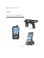
AT570
Windows CE® .NET Ruggedized PDA
ATID Co., Ltd.
ATID Co., Ltd.
#1210, Byuksan/Gyungln Digital Valley II, #481-10,
Gasan-Dong, Gumchon-Gu, Seoul, Korea
Telephone: +82-2-544-1436
Fax: +82-2-2113-0040
www.atid1.com
c 2006 ATID Co., Ltd. An Unpublished Work – All right reserved. No part of the
Copyright ○
contents of this documentation or the procedures described there in may be reproduced or
transmitted in any form or by any means without prior written permission of ATID Co., Ltd.. or
its wholly owned subsidiaries ("ATID ").
Owners of ATID products are hereby granted a non-exclusive, revocable license to reproduce
and transmit this documentation for the purchaser's own internal business purposes.
Purchaser shall not remove or alter any proprietary notices, including copyright notices,
contained in this documentation and shall ensure that all notices appear on any reproductions
of the documentation.
Should future revisions of this manual be published, you can acquire printed versions by
contacting ATID Customer Administration. Electronic versions may either be downloadable from
the ATID web site (www.atid1.com) or provided on appropriate media. If you visit our web site
and would like to make comments or suggestions about this or other ATID publications, please
let us know via the “ Contact ATID ” page.
Disclaimer
Reasonable measures have been taken to ensure that the information included in this manual is
complete and accurate. However, ATID reserves the right to change any specification at
anytime without prior notice.
ATID is a registered trademark of ATID Co., Ltd..
The ATID logo is a trademark of ATID . All other trademarks and trade names referred to herein
are property of their respective owners.
AT570 is a registered trademark of ATID Co., Ltd.. and of its wholly owned subsidiaries.
Microsoft Windows®, Windows® 2000, Windows® CE .NET, Windows® NT, and Windows® XP
are registered trademarks of Microsoft Corporation.
2
AT570 Reference Guide
Contents
Before You Begin ....................................................................................6
Chap1. Using The AT-570 ......................................................................7
1. Introducing ..........................................................................................7
1.1
1.2
1.3
1.4
Features ...........................................................................................................................7
View of the PDA #1 .........................................................................................................8
View of the PDA #2 .........................................................................................................9
Table Features Function/Description............................................................................10
2. Power................................................................................................12
2.1 Power ON/OFF...............................................................................................................12
2.1.1 Power ON.............................................................................................................12
2.1.2 Power OFF...........................................................................................................12
2.1.3 What is idle mode?..............................................................................................12
2.1.4 Suspend mode ....................................................................................................13
2.2 Battery............................................................................................................................13
2.2.1 Checking Battery Power ......................................................................................13
2.2.2 Very Low Battery Status ......................................................................................13
2.3 Removing and installing the battery ..............................................................................13
2.3.1 Removing the battery ..........................................................................................13
2.3.2 Installing the battery ............................................................................................13
2.4 Battery discharging........................................................................................................13
2.5 Recharging the battery ..................................................................................................13
2.5.1 Using the adapter ................................................................................................13
2.5.2 Using the Dock ....................................................................................................14
2.6 Backup Battery ..............................................................................................................15
2.7 Disposal of the spent battery ........................................................................................15
3. Setting up the AT-570 .......................................................................16
3.1
3.2
3.3
3.4
3.5
3.6
3.7
3.8
3.9
Power On .......................................................................................................................16
Power Off.......................................................................................................................16
Adjusting the Brightness................................................................................................16
Calibrating the screen ...................................................................................................17
Adjusting the Volume.....................................................................................................17
Setting up the Date and Time .......................................................................................18
Power Configuration ......................................................................................................18
Schemes Tab .................................................................................................................18
Memory Allocation .........................................................................................................19
4. Resetting the PDA ............................................................................20
4.1 Warm Reset....................................................................................................................20
4.2 Hard Reset (cold reset) .................................................................................................20
5. Flash Disk .........................................................................................21
5.1 Hard reset ......................................................................................................................21
5.2 Warm reset.....................................................................................................................22
5.3 Return back to the existing place..................................................................................23
6. Registry Backup................................................................................24
3
Quick Reference Guide
7. Using the keypad ..............................................................................25
7.1 Change current character..............................................................................................25
7.2 Inputting the data ..........................................................................................................25
7.3 Setting device though the <Fn> key .............................................................................26
8. Using the stylus ................................................................................26
9. Using the Hand-strap and Gun hand-held .......................................27
Chap 2. Windows Program...................................................................28
1. Basic Information ..............................................................................28
1.1 Task Bar and Command Bar .........................................................................................28
1.2 Pop-up Menus...............................................................................................................29
2. Executing a Program ........................................................................29
3. Entering information .........................................................................29
3.1 Using the Onscreen keypad ..........................................................................................29
3.2 Using the Transcriber ....................................................................................................30
4. Customizing Your AT-570 .................................................................31
4.1
4.2
4.3
4.4
Adjust settings ...............................................................................................................31
Adding or Removing the Programs ...............................................................................31
Adding the Programs Using ActiveSync .......................................................................31
Removing the Programs ................................................................................................32
5. Microsoft ActiveSync ........................................................................32
5.1
5.2
5.3
5.4
Using Microsoft ActiveSync...........................................................................................32
Installing Microsoft ActiveSync on your desktop ..........................................................32
Setting up a Partnership................................................................................................33
Transferring Files ...........................................................................................................33
6. Microsoft WordPad ...........................................................................33
7. Window Media Player .......................................................................34
8. Internet Explorer ...............................................................................34
9. Context Sensitive Help .....................................................................35
Chap 3. Optional Module (Version 1.1) ................................................36
1. 1D barcode Scanner.........................................................................37
1.1 1DScanner(Demo program) ..........................................................................................37
1.2 Setting up the AT1DEmulator ........................................................................................40
1.3 Setting up the 1D Barcode Symbology.........................................................................42
2. 2D barcode Scanner.........................................................................44
2.1 Reading 2D barcode & Symbology Setting...................................................................44
2.2 Setting the AT2DEmulator .............................................................................................46
2.3 Scanning Barcode .........................................................................................................48
3. Wireless LAN ....................................................................................50
3.1
3.2
3.3
3.4
Power on Wireless LAN .................................................................................................50
IP Information ................................................................................................................51
Setting manually ............................................................................................................52
Power Off Wireless Off..................................................................................................52
4. Bluetooth...........................................................................................53
4.1 To enable Bluetooth ......................................................................................................53
4
AT570 Reference Guide
4.2
4.3
4.4
4.5
Bluetooth Manager ........................................................................................................53
Connecting Bluetooth Printer(SPP) ...............................................................................53
Reference for Application Developer ............................................................................57
Disconnecting Bluetooth Printer(SPP) from AT-570 ....................................................58
5. 13.56MHz ATID Multi (R/W)Reader .................................................60
5.1 Optional Types...............................................................................................................60
5.2 Executing ATIDMultiReader ...........................................................................................61
6. UHF 900Mhz(Read / Write) Reader .................................................64
6.1 UHF 900Mhz(Read / Write) program.............................................................................65
7. GPS Module .....................................................................................70
7.1 Executing the GPS.........................................................................................................71
7.2 Configuring the Port and Baud Setting for Executing the GPS ....................................71
7.3 Checking the GPS status...............................................................................................73
8. GSM/GPRS ......................................................................................74
8.1 Executing Phone UI .......................................................................................................74
8.2 Phone Screen ................................................................................................................74
9. Using Camera...................................................................................76
9.1 To use your Camera: .....................................................................................................76
5
Quick Reference Guide
Before You Begin
This section provides you with safety information, technical support information, and sources
for additional product information
Who should read this manual?
This manual is written for the person who is responsible for installing, configuring, and
maintaining the AT-570.
This manual provides you with information about the features of the AT570, and how to install,
configure, operate, and maintain it.
Before you work with the AT570, you should be familiar with your network and general
networking terms, such as IP address.
Safety information
Your safety is extremely important. Read and follow all warnings and cautions in this
document before you handle and operate ATID equipment. You can be seriously injured, and
equipment and data can be damaged if you do not follow the safety warnings and cautions.
WARNING
A warning alerts you to an operating procedure, practice, condition, or statement that must
be strictly observed to avoid serious injury to the person who working on the equipment
CAUTION
A caution alerts you to an operating procedure, practice, condition, or statement that must be
strictly observed to prevent equipment damage or destruction, or corruption or loss of data.
NOTICE
A notice makes you have more information while you use AT-570
6
AT570 Reference Guide
Chap1. Using The AT-570
This chapter introduces the AT570 Mobile Computer to enhance wireless connectivity needs
and contains hardware and software configuration to assist you in making the most out of
your AT570.
1. Introducing
The ATID AT570 mobile computer is a small, ergonomically designed mobile computer built
on the Microsoft window CE NET 5.0 operating system. The PDA uses an Intel® Bulverde
CPU and a 3.5” VGA, color Touch screen display. The PDA supports wireless LAN 802.11b/g
(embedded module) for communication.
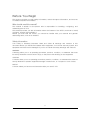
1.1 Features
Remove all the items from the packing box, and check to make sure all the parts are present:
1
3
1.
2.
3.
4.
5.
6.
2
AT570 PDA
Power Adaptor
Lithium Ion Battery Pack
Synchronization Cable
Stylus
Hand strap
2
4
5
6
Figure 1. In the Packing box
7
Quick Reference Guide
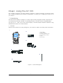
1.2 View of the PDA #1
Refer to Table 1 for a list and description of the illustrated features.
11. Speaker
1. LCD/Touchscreen (Display)
13.Navigation Key
14. KBD Key
12. Power Key
15. Reset Key
22. Low
Battery LED
6. Power LED/Alarm
Indicator
4. WLAN ON/OFF
Alarm
16. Key Pad
Figure 2. Front View
2. Scan key
(Left & Right)
10. Antenna for
GSM/GPRS and
CDMA
5. Secure Digital
(SD) Slot
21. MIC
17. Ear Jack
Figure 3. Side view
8
AT570 Reference Guide
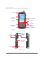
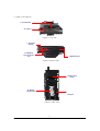
1.3 View of the PDA #2
3. Scan Window
23. Camera
Figure 4. Top view
7. DC Power
Adaptor
8. USB/Serial
Synchronization
Port
9. USB Host Port
Figure 5. Bottom view
19. Hand strap
Holder
18. Battery
Compartment
20. Stylus
Figure 6. Rear view
9
Quick Reference Guide
1.4 Table 1 Features Function/Description
Features
1.LCD/Touchscreen
2.Scan key
(Left and Right)
3.Scan Window
4. 22.WLAN
ON/OFF display
light
5.Secure Digital
(SD) Slot
6.Power LED /
Alarm Indicator
7.DC Power
Adaptor Port
8.USB/Serial
Synchronization
Port
9.USB Host Port
10.Anttena
11.Speaker
12.Power/ Key
13.Navigation Key
Function/Description
LCD touch screen displays information and data.
You can see the results of your work trough the LCD touch screen. The AT570 has a stylus
you can use to select items and inter information.
Caution: Do not use a pen, pencil, or other sharp object on the AT570’ s touch screen. Use
only the supplied stylus or plastic-tipped pens intended for use with a touch-screen
sensitive display.
Use either the right or left <Scan> button to activate the scanner and read a bar code. The
scanner starts to read the bar code. The scanner automatically turns off either when the
barcode is read, when you release the scan button, or after 10 seconds, which ever comes
first.
The scanning beam is emitted from this aperture. Aim the scanning beam at the bar code
you wish to scan.
Refer to "Scanning Bar Codes" on page 23 for more information.
It makes you know that the WLAN is on or off.
The secure digital card slot accepts a secure digital storage card. Refer to the iPC320
Product Reference
Guide for installation instructions.
When the battery pack is installed in the PDA and charging in the Dock, this LED is Red.
When the battery is completely charged, the LED changes to Green. When the LED flashes
blue, it indicates a low battery. Some applications use a blue LED to indicate an Alarm or
Error.
Connect the external power adaptor to this port to charge the battery. You must charge the
batteries for thirteen (13) hours prior to first use. Charge the battery completely.
Subsequent charge cycles require four (4) hours.
To synchronize data between a PC and the PDA, connect the USB or Serial cable with
Desktop and the PDA.
You must download and install Microsoft ActiveSync 3.7 or higher in the PC. Download
ActiveSync from the Microsoft Web site at www.microsoft.com.
The USB Host port can be used with a USB keyboard, mouse, compact flash card, and/or
Ethernet connection. When using the dock, you can use standard a USB host port to
connect USB peripherals.
The USB Host Port supports only peripherals with low power consumption.
Antenna for CDMA, GSM/GPRS etc.
The speaker emits the sounds from *.WAV and other media files. It can also be set to emit
beeps or tones to indicate errors or good reads when bar code scanning and inputting data
using the keypad or stylus.
Press the Power/Backlight key briefly to turn the unit on. The Backlight comes on
automatically.
Press this key again briefly to turn the unit off.
Press the edge of the 4-way navigation rocker key to move the cursor or highlighted text
entry during a menu/list selection.
• The <Up> arrow moves the cursor up one line.
• The <Right> arrow moves the cursor to the right one character.
• The <Down> arrow moves the cursor down one line.
• The <Left> arrow moves the cursor to the left one character.
For more information on each of these features, please contact Q&A of ATID Home (www.ATID1.com).
10
AT570 Reference Guide
Features
14.KBD key
Function/Description
KBD key executes input panel (SIP)
Press again, input panel (SIP) disappears
15.Reset Key
Use (R/S) button located on the Keypad of PDA to perform a soft and hard reset.
Please refer to the section 4 – Resetting the PDA.
16.Keypad
Use the alpha-numeric, function, and navigation keys on the keypad to enter numbers,
letters, symbols and navigate. For details on each key in the keypad, please refer to the
section 7 - Using the Keypad.
17.Ear Port
Connect the Ear/Microphone to listen to audio files using the media player, or communicate
with others using an application such as GSM.
18.Battery
Compartment.
Insert battery charged fully in this compartment.
19.Handstrap
The PDA comes with the hand strap, which is easily removable to access features and can
be replaced by an ergonmically designed handle.
20.Stylus
Use the stylus for navigation, on the soft input panel (SIP), and to select items on the touch
screen. It is a good idea to replace the stylus in the holder after each use so you don’ t lose
or misplace it.
21.MIC
22. Low Battery
LED
Use it, when you are calling trough GSM
The battery becomes red and blinks automatically, when it is in the “ low Battery Status”
For more information on each of these features, please contact Q&A of ATID Home (www.ATID1.com).
11
Quick Reference Guide
2. Power
This section introduces the power system of AT570 such as power switch and battery.
2.1 Power ON/OFF
2.1.1 Power ON
1. Press power key, the AT570 and the backlight will be on.
2. To save power and prolong the battery, the screen gets to be off, when the AT570
goes into idle mode. And it is easy to resume activity. Just tap the screen or press
any key on the keypad.
2.1.2 Power OFF
1. Press power key, you actually suspend the AT570 and turn off the display and
backlight.
2. The other method: Tap start > Suspend
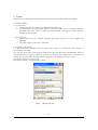
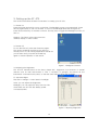
2.1.3 What is idle mode?
It is the period that computer goes on without any activity for a long time, but it doesn’ t
have influence on data
You can set up the idle mode and the PDA will go into the idle mode automatically after the
interval that you set goes to the end. It helps you prolong your battery life. If you want to
restart your AT-570 while the PDA goes into idle time, tap anywhere on the screen.
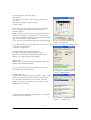
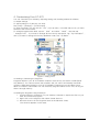
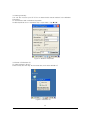
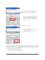
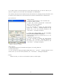
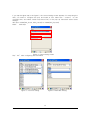
To change the time into idle mode
Tap Start > Setting > Control Panel > Power
Figure 1. Setting Idle time
12
AT570 Reference Guide
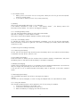
2.1.4 Suspend mode
1. When you do not use AT-570 for a long time, make your AT-570 go into the suspend
mode for saving power.
2. If you want to restart your AT-570, press power key.
2.2 Battery
AT570 uses replaceable 4400 mAh, Li-ion batteries.
If the battery continues to drop to the “ Low Battery Status” , the battery status LED
becomes red and blinks. You need to recharge the battery.
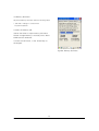
2.2.1 Checking Battery Power
You can check the battery status by using the power applet.
Tap Start > Settings] > Control panel > Power
The power control panel applet displays a battery power gauge.
2.2.2 Very Low Battery Status
To prevent the AT570 from being discharged completely, your AT-570 will be suspended,
when the battery continues to get low. You need to recharge your battery before the battery
continues to drop.
2.3 Removing and installing the battery
2.3.1 Removing the battery
At first, pull out the hand scrap and then press the battery latch to the above until the battery
is released from the AT570, then lift it out.
2.3.2 Installing the battery
Insert the bottom of battery into the sunken place located in battery compartment, and press
the battery latch to the above until the battery is installed completely.
2.4 Battery discharging
Several factors determine the life of your battery such as extreme temperatures, input devices,
and your usage, but generally you can use AT-570 for 6~12hours.
If the AT-570 is not on external power and battery pack is removed, it will enter suspend
mode.
2.5 Recharging the battery
Use the adapter provided from ATID to recharge your battery.
Caution
Your AT-570 can be damaged, in case of using the adapter that is not provided from ATID.
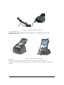
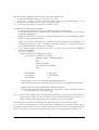
2.5.1 Using the adapter
The charge/operating power can be applied to AT-570 by using DC adapter.
1. Connect the adapter to the power cord.
2. Connect the DC power jack to the AT-570.
3. When the battery is charging, the LED becomes red.
13
Quick Reference Guide
Figure 2. Using the adapter to recharge
2.5.2 Using the Dock
The Dock is for charging AT570, and the dock is one of which also can act as a
communication port.
Figure 3. Using the Dock to recharge
CAUTION
Make sure the AT570 is firmly seated in the dock, charger, or power adaptor.
If it is not firmly seated, battery charging and communication with the Host PC will NOT be
initiated.
14
AT570 Reference Guide
2.6 Backup Battery
The backup battery in the PDA is a 200mAh rechargeable battery that holds system data at
least 2 hours without main battery.
CAUTION
If you remove the battery or the battery completely discharges, there is a two(2)hour window
in which to insert a charged battery before the backup battery completely discharges and the
contents of the RAM memory are lost. It is a good idea to keep your data and applications in
Flask Disk for that reason. Refer to “ Flash Disk” for more information.
If both the battery pack and the backup battery are allowed to discharge completely, you
must recharge both batteries for thirteen (13) hours.
The backup battery is charged off the battery pack, so it is important to keep the battery pack
with at least a minimal charge so the unit can maintain date, time, data, and other settings.
2.7 Disposal of the spent battery
When the battery reaches the end of its useful life, the spent battery must be disposed by a
qualified recycler or material handler
Warning
Do not mix the spent battery with the solid waste stream and keep away from children.
15
Quick Reference Guide
3. Setting up the AT-570
This section describes the basic information for setting your AT-570.
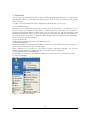
3.1 Power On
Press the Power key briefly to turn on the PDA. The Backlight comes on automatically. Press
this key again briefly to turn off the PDA. To turn off the Backlight while the PDA goes on,
press and hold the key for at least a second. This key acts to toggle the Backlight function off
and on.
Desktop: The figure at the right shows the
desktop display, or main screen.
3.2 Power Off
To turn the PDA off, press the Power key again.
This action suspends the device, but does not
actually turn it off. All running applications remain as
you left them until you press the Power key
again to resume operation of the device.
Figure 1. Background Screen
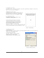
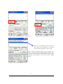
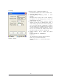
3.3 Adjusting the Brightness
The AT-570 manufactured at the factory keeps 80% brightness, but because of several
reasons such as dark environment or user’ s condition of eyesight, and above all, the
illumination consumes much power, so that the users want to adjust the backlight.
To adjust backlight:
Tap Start > Settings > control panel > backlight
Level: you can adjust the brightness
Backlight: you can adjust the entry time into idle
mode when use AT-570 with battery power
or external power.
Figure 2. Adjusting Brightness
16
AT570 Reference Guide
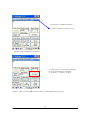
3.4 Calibrating the screen
According to user’ s personal treatment, and activity, applications installed in the AT-570
need to be set up after purchasing it.
Calibrating the Touch Screen
Thought the screen is already calibrated, but if you
have feeling that your screen isn’ t responding
properly to your tap, you can recalibrate it again.
To recalibrate the screen
Tap start > Settings > Control panel > Stylus
> Calibration > Recalibration
Press and briefly hold stylus on the center
of target, and repeat 5 times as the target
moves around the screen. The screen counts
30 seconds after calibrating, and you can
finish the recalibration to touch screen
wherever you want. If you did not have any action, the
screen will automatically finish the recalibration of itself.
Figure 3. Recalibrating
3.5 Adjusting the Volume
Volume & Sounds
Your AT-570 manufactured at factory is set at the maximum volume, so you can adjust the
volume if you need suitable sound.
To adjust Volume & Sounds
Tap Start > Settings > Volume & Sounds
Volume tap: tap to adjust Volume
Sounds tab: tap to set the imitated sounds
Figure 4. Adjusting volume
17
Quick Reference Guide
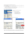
3.6 Setting up the Date and Time
Date & time
You can set the current time located at the bottom
of screen.
Tap Start > Settings > Control Panel
> Date & Time
Year: Select the year, then the spin control appears.
Try to set the year though the navigation key or
up/down button.
Month: Select the month directly, then the full months
of one year appear. Try to select the correct month.
You can also select the month though the left/right key.
Day: Just tap a day in the calendar.
Time: you can set the time though the up/down button.
Figure 5. Date/Time
If you set the time zone one time, you can set the correct local time easily by changing the
location into where you are.
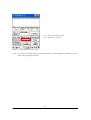
3.7 Power Configuration
To adjust power management settings,
Tap Start > Settings > Control Panel > Power
Use this control panel to check the charge on the
battery or to change the Power settings.
Battery Tab
Battery tap: It shows the power remained in the main
battery and the backup battery.
To exit, press OK from the command bar, or press
the <Enter> key on the keypad.
Figure 6. Battery status
3.8 Schemes Tab
It allows you to determine the entry time of user’ s idle
mode, system idle mode, and suspend mode while
you use either main battery or AC power. This will
helps you to save more power, if you have to move
repeatedly on your work.
To exit, press OK from the command bar, or press the
<Enter> key on the keypad.
Figure 7 . Schemes Tap
18
AT570 Reference Guide
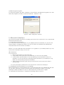
3.9 Memory Allocation
Adjust the Memory Allocation with the following steps:
1.Tab Start > Settings > Control Panel
> System Properties
2.Seletc the Memory tab.
3.Move the slider to adjust memory allocation.
Default storage Memory is normally set to about
8 MB with the remainder.
4. Press the OK button, or the <Enter>key on
the keypad.
Figure8. Memory Allocation
19
Quick Reference Guide
4. Resetting the PDA
When the AT-570 completely stops responding for your command, or an application is locked
up and does not respond, and when you want to upgrade the firmware, it may be necessary
to perform a reset.
Caution
Always attempt a Warm reset before initiating a Cold reset. Once you initiate a cold reset, all
applications are forcibly closed and working RAM and files are cleared.
It is a good idea to store important data in the resident (Flash Disk) for this reason.
Warning
Do not use force or a sharp object like paper clip to press the reset button. Use the stylus for
that purpose. Sharp object like paper clip could puncture the seal of the reset key.
4.1 Warm Reset
When you should perform the warm reset?
When you cannot turn on or off a program, or execute other programs because of
“ hang” -the system error that stops responding. The “ warm reset” for recovering the
AT-570 is to press R/S button on the front of AT-570. This method not guarantee that
cashed disk data will be saved, so transactional data maybe lost during the reset.
Procedure to Warm Reset. To initialize warm reset, press and hold the <Reset> key.
After Warm Reset
• The splash screen will appear shortly.
• The desktop appears with the application shortcuts on the screen.
• The custom settings in the registry are persistent.
• The RF Network PC Card if present, connects to the network system.
4.2 Hard Reset (cold reset)
When you should perform the cold reset?
If the performed reset method fails to restore system operation, it may be necessary to
perform a hard reset. This is a boot method that formats the object store to clean data and
registry information from the AT-570 system and restores them to their factory-default state.
This will erase the memory in the AT-570, including all applications and data files found in the
object store (user store).
A Hard reset is a complete reset of the PDA in which all applications are forcibly closed and
working RAM and files are cleared.
Hard Reset Procedure. To perform a Hard reset, simultaneously press the <Reset> key with
the stylus while pressing the <power> key.
After Hard Reset.
When a PDA goes through the Hard reset sequence, it clears the working RAM and initializes
the file system.
• The splash screen will appear shortly.
• You will be asked to recalibrate the touch screen. Press the <ESC> key to circumvent
recalibration.
20
AT570 Reference Guide
•
•
•
•
The desktop appears with the application shortcuts on the screen.
The custom settings in the registry are persistent.
The RF Network PC Card if present, connects to the network system.
The application saved in Flash Disk will not be deleted after cold reset (refer to section 5
Flash Disk)
5. Flash Disk
In addition to the RAM-based storage standard on Windows CE .NET terminals, the AT-570 is
also equipped with a Flash Disk, and all the application and data in the Flash Disk can be
persisted in its own condition after the hard reset. From this point of view, it is a kind of very
useful method to keep important application and execute user’ s own application
automatically after the hard reset.
To save your application program, please keep these following steps in your mind.
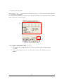
5.1 Hard reset
1. At first copy an execute file you want to re-execute.
2. Double-tap My Device > Flash Disk > Open Start folder >Open Hard Reset folder
3. Paste the copied file in the Hard Reset Folder.
ㅇ
Fitgure1. Click Flask Disk
Figure2. Click Start folder
21
Quick Reference Guide
Figure 3. Open the HardReset folder
Figure4. An application in the HardReset folder
If you don’ t want to execute the application copied in the Flash Disk, after the hard reset is
performed, press the “ Fn” key during the hard reset.
5.2 Warm reset
1. At first copy an execute file you want to execute after warm reset.
2. Double-tap My Device > Flash Disk > Open Start folder > Open Reset folder
3. Paste the copied file in the Reset folder.
Figure 5. Open Reset Folder
Figure 6. An application in theReset folder
22
AT570 Reference Guide
If you don’ t want to execute the application copied in the Flash Disk, after the Warm reset is
performed, press the “ Fn” key during the Warm reset.
5.3 Return back to the existing place
When a PDA goes through the hard Reset sequence, it clears the working RAM and initializes
the file system, but because of Flash Disk you can make your files return back to their existed
place after the Hard Reset get performed. This method is also very useful to configure your
system without any action after the hard Reset.
To make files get replaced:
Copy files you want to replace after the hard reset.
Double-tap My Device > Flash Disk > Open CopyFile
Figure 7. Click CopyFile
Figure 8. Copy files you want to replace
To make your files return back to the background screen (\Windows\Background) after
Hard Reset, paste your Files into the Desktop folder.
To make your files return back to programs (\Windows\Programs) folder after Hard Reset,
paste your Files into the Programs folder.
To make your files return back to Windows (\Windows) after Hard Reset, paste your Files
into the Windows folder.
23
Quick Reference Guide
6. Registry Backup
Your AT-570 is preparing the Registry Backup program for solution to save the user’ s
registry. This is a very useful method to restore your AT-570, when you perform the hard
reset, and even if it is discharged completely.
The main function of registry:
1. Makes connection between WLAN and AP.
2. Execute RegistryBackUp program and save registry.
3. Restores the connection between WLAN and AP after hard or soft reset.
To save registry:
Tap My device > Windows > Double-tap Registry Backup
Figure 1. Registry BackUp
Figure 2. Save or delete registry
Figure 3. Registry Save
24
AT570 Reference Guide
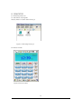
7. Using the keypad
The keypad is useful to input data and most of the keys on the keypad have more than one
function. Try to input data with the keypad after know how to use it and keep the intimate
knowledge like following tips in your mind.
7.1 Change current character
To change the current input character type, press the <key> key, than you can see the
changed current key type like following steps:
Numeric > Lowercase > Uppercase > Special
Figure4. Changing Current Character
7.2 Inputting the data
Numeric Mode: After making your choice to the Numeric Mode through the<key> key, and just
press from 1 to 10 numeric keys.
Alpha Mode: In alphabetical order, there are 2~3 letters per key.
To input the first letter, press the key you want input one time, and to input the second and
third letter, press the key how many times as the letter is ordered on the key continuously.
Special character: After making your choice to the Special Mode through the<key> key, press
the key that has special character you want to input.
25
Quick Reference Guide
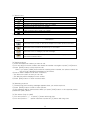
7.3 Setting device though the <Fn> key
Press <Fn> + other keys simultaneously to activate follows.
Table3.key describe
Fn +
Function
Navigation <Up>
Increase sound.
Navigation <Down>
Decrease sound.
<Esc> Key
WLAN ON / OFF
2
Execute App1 program.
3
Execute App3 program.
4
Copy clip board.
5
Add to clip board.
Setting App
To execute the program designated by user directly:
Tap Start > Control panel > Application Buttons and designate App1, App2 as you want to
execute anytime.
l
KBD button: you can make the touch screen display the input panel program directly to press
the KBD button on the front of the AT-570.
8. Using the stylus
The stylus is located next to the Battery pack on the right rear of the PDA. The stylus on the
PDA is the equivalent of the mouse on a PC.
Warning: Never use a pen, pencil, or other sharp object on the AT570’ s touch screen display.
Use only the supplied stylus or plastic-tipped pens intended for use with a touch
screen-sensitive display.
Use the stylus to:
*Navigate the touch screen display.
*Select characters in the soft input panel (SIP).
*Select applications from the desktop or system tray.
*Select buttons, tabs, fields and text within applications and dialog boxes.
26
AT570 Reference Guide
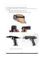
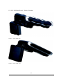
9. Using the Hand-strap and Gun hand-held
To use the PDA for extended periods of time, install the hand-strap for increased comfort
and usability.
1. Turn the PDA face down and ensure the power in off.
2. Insert strap into strap holder and pull down for fixing.
3. Pull plastic tab up to insert the strap recess at the top of the unit.
Figure 1. Using the hand-strap
Figure 2. The Gun-typed hand-held
27
Quick Reference Guide
Chap 2. Windows Program
This chapter introduces Microsoft Windows Mobile 5.0 for Pocket PC. While using the ATID
Mobile Computer, keep these key points in mind:
1) Tap Start on the navigation bar, located at the bottom of the screen, to quickly move to
programs, files, and settings.
2) Tap and hold an item to see a pop-up menu containing a list of actions you can
perform.
1. Basic Information
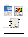
1.1 Task Bar and Command Bar
The task bar is located at the bottom of the screen. It displays the active program and current
time, switch to programs, input panel, and battery status.
Command bar
Input panel
WLAN status
Battery status
Current program
Tap to start a program
Figure 1. Task Bar and Command Bar
Use the command bar to perform tasks in programs. The command bar includes menu names,
functions.
28
AT570 Reference Guide
1.2 Pop-up Menus
Use pop-up menus to quickly perform an action on an item. For example, you can use a
pop-up menu to delete or copy of an item. To access a pop-up menu, tap and hold the item
on which you want to perform the action. When the menu appears, tap the action you want to
perform, or tap anywhere outside the menu to close the menu without doing the action.
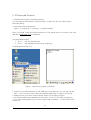
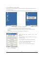
2. Executing a Program
When you turn on the AT-570 for the first time, you can
see the following start screen. Try to double-tap
“ My device” Icon > windows > Program >
tap an icon you want to execute.
You can also display it by tapping the Start flag at the
bottom left of your display.
Figure 2. Executing a Program to use Start Flag
3. Entering information
You can enter information on your AT-570 in several ways, depending on the type you have
and the program you are using.
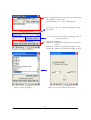
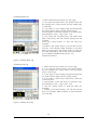
3.1 Using the Onscreen keypad
Use the input panel to enter information in any program on your AT-570.
You can both type using onscreen keyboard or write using transcriber.
Double-click
Figure 3-1. Selecting SIP menu
Figure 3-2 Popping-up SIP
To make pop-up menu appears, double-tap the keypad icon on the taskbar.
To make soft input panel (SIP) popped up, tap the keypad icon on the taskbar, or press
“ KBD/)) “ key on the keypad.
29
Quick Reference Guide
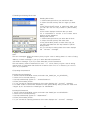
To see Soft Keyboard Option:
Tap Start > Settings > Control Panel > Input panel, select “ keyboard” from the current Input
method drop-down list, tap “ option” , then adjust Options as you want to use.
Figure 4. Keypad Option
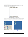
3.2 Using the Transcriber
With Transcriber, you can write anywhere on the screen using the stylus just as you would on
paper. Double-tap input panel icon, than tap Transcriber. After selecting, than write anywhere
on the screen.
Figure 5. Using Transcriber in an application program
30
AT570 Reference Guide
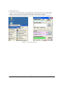
4. Customizing Your AT-570
You can customize your mobile by adjusting setting and installing additional software.
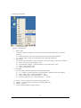
4.1 Adjust settings
To adjust settings to fit the way you work:
Tap [Start] > [Settings] > [Control Panel]
To open a program, you can use the “ File” pop-up menu, or double-tap an icon you want
execute in the Control Panel.
To arrange programs with detail, tap the “ View” and select “ Detail” , and than tap
“ Arrange Icons” . If you want to arrange all the icons by description, tap “ By Description” ,
and if you want to arrange all icons by alphabetic order, tap “ By Name” .
Figure 1. Setting Icons
4.2 Adding or Removing the Programs
Programs added to your AT-570 Mobile computer at the factory are stored in ROM (Read
Only Memory). You cannot remove this software, and you cannot accidentally lose ROM
contents. Applications added to your AT-570 Mobile computer go into the Object Store,
Which is located in Flash ROM. You can install any program created for AT-570, as long as
there is enough memory.
4.3 Adding the Programs Using ActiveSync
1. Use the Explore in ActiveSync on your desktop computer to explore the files on your
PDA, and locate the program.
2. Right-click on the program, then select Create Shortcut.
3. Move the shortcut to the Programs folder in the Windows folder.
The shortcut appears on the menu.
31
Quick Reference Guide
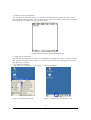
4.4 Removing the Programs
To remove a program, tap Start > Settings > Control Panel > tap Remove Programs Icon, than
select the program you want to remove. Press the “ Remove” tap.
Figure 2. Input a program to remove
5. Microsoft ActiveSync
This section provides instructions on setting up the Host PC so that the PC can communicate
with the PDA and the dock.
5.1 Using Microsoft ActiveSync
You can synchronize the information on your desktop with the information on your AT-570.
Synchronization compares the data on your AT-570 with your desktop and updates both
computers with the most recent information
NOTICE : You must have Microsoft ActiveSync 4.2 or greater on your desktop before you can
synchronize information with your AT-570.
With ActiveSync
You can also do:
1. Back up and restore your AT-570 data
2. Copy (rather than synchronize) files between your AT-570 and desktop.
3. Control when synchronization occurs by selecting a synchronization mode. For
example, you can synchronize continually while connected to your desktop or only
when you choose the synchronize command.
4. Select which information types are synchronized and control how much data is
synchronized.
For more information, please refer to the instruction of Microsoft ActiveSync.
5.2 Installing Microsoft ActiveSync on your desktop
Microsoft ActiveSync is a file transfer tool to synchronize the files on a desktop with the files
on your PDA. The AT570 comes from the factory with ActiveSync loaded. If you have
ActiveSync already installed on your PC, make sure that you have v4.2 or higher.
To install Microsoft ActiveSync, complete the following steps on the PC:
32
AT570 Reference Guide
1. Go to the Microsoft Windows CE .NET website and download the most current
version of ActiveSync http://www.microsoft.com/mobile/pocketpc/downloads/.
Install the most current version of Microsoft ActiveSync (v4.2 or greater) on the host
PC.
2. Once ActiveSync is installed, it will attempt to connect to the AT570; allow it to fail on
the first attempt.
5.3 Setting up a Partnership
ActiveSync file synchronization requires an ActiveSync partnership between the AT570 and
the Host PC.
Setting up a Partnership.
1. Select the files in the synchronization configuration for the AT570.
2. Select Tools > Options from the ActiveSync command bar to configure the
synchronization options.
Place the file to be synchronized in the Synchronization folder created in your My Documents
directory. During the ActiveSync connection, all files in the Synchronization folder will be
synchronized to the My Documents directory on the AT570.
5.4 Transferring Files
To transfer files, complete the following steps on the host PC:
1. Select Start > Programs > Microsoft ActiveSync
2. Double-click on the ActiveSync icon in the System Tool Tray.
3. After you have established a connection with your PDA, tap the Explore button at the
top of the ActiveSync window (or select Explore form the File menu). Navigate to
the target directory on your portable and copy the desired file by using the Copy/Paste
method or dragging and dropping the desired file(s) into the folder.
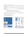
6. Microsoft WordPad
Use Microsoft WordPad to create documents, such as letters or meeting minutes.
Select Start > Programs > Microsoft WordPad
The PDA comes with WordPad for Windows CE .NET installed from the factory. The following
text and document file types are compatible with WordPad:
Text (*.txt ), Word Document (*.doc ), Rich Text File (*.rtf ), WordPad (*.pwd )
When you transfer file types other than *.pwd to the Windows CE .NET device, it translates
the files into a compressed Windows CE .NET file type.
Figure 1. WordPad.
33
Quick Reference Guide
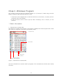
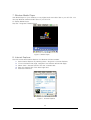
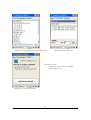
7. Window Media Player
Use Media Player on your desktop to copy digital audio and video files to your AT-570. You
can play Window media and MP3 files on your AT-570.
To display Media Player:
Tap Star > Programs > Media Player
Figure 1. Media Player
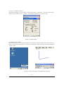
8. Internet Explorer
The PDA comes with Internet Explorer for Windows CE.Net installed
1. Open Internet Explorer by selecting Start > Programs > Internet Explorer.
2. To set a default home page, navigate to the desired default web page.
3. Select View > Internet Options from the command bar.
4. Enter the desired URL in the Start Page field.
5. Press the OK button.
Figure 1. Internet Explorer
34
AT570 Reference Guide
9. Context Sensitive Help
Microsoft Windows CE context sensitive help is available where ever a “ ?” button appears
in the upper right hand corner of the window. To open context sensitive Help, select/tap the
“ ?”
in the upper right corner of most screens. Select/tap the desired item from the list of
hot links.
Figure 1. Sensitive Help
35
Quick Reference Guide
Chap 3. Optional Module (Version 1.1)
The automatic identification and wireless network technology has helped users to keep their
information, and makes IT engineers try various methods to develop modules used within
mobile computer. The AT-570 can also be supported with the optional modules for the needs
of users. This section provides you with the information of the Optional Modules, and sources
for additional product information. You need to confirm the follow information before you get
the device that you want to use.
The Optional modules supported from ATID
Note: According to user’ s purpose or Upgrading for device, the additional information can be
changed.
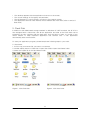
1) Barcode Reader
-. 1D Scanner Barcode Reader
2) Barcode Reader
-. 2D Scanner Barcode Reader
3) Wireless Lan – 801.11 b.g
4) Bluetooth (Stack Service – Only Supports SPP)
5) UHF 900 M – Gen 2 Full Function
ISO18006b(Only Tag UID Reader)
Size of Antanna
-. Large Type Antanna ( 800mm X 800mm X About 8mm)
-. Small Type Antanna ( 400mm X 400mm X About 8mm)
6) RF 13.56 – Mifare, ISO15693
-. Integrated in the PDA
-. Integrated in the Gun type device
7) GPS Module
The Options to install the GPS Module
-. GPS Module designed to be installed on the top of the AT570
-. GPS Module designed to be installed on the rear of AT570.
-. GPS Module designed to be installed on the Car Cradle.
8) GSM/GPRS / CDAM
9) Camera
36
AT570 Reference Guide
1. 1D barcode Scanner
This chapter introduces the AT570 built in with the 1D, 2D barcode Scanner program to assist
you in making the most out of your AT570
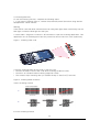
1.1 1DScanner(Demo program)
You can execute AT1DTScanner coded from ATID to make sure that your AT570 scans
barcodes exactly.
Figure 1. Scan Window for 1D image
Figure 2. Scan Window for 2D image
1) To execute Scanner Diagnostics
Tap [start] -> [program] -> [Scanner] -> [AT1DTScanner]
Note: If you don’ t have AT1Dscanner.exe(Ver 1.2) File, please look for our staff or visit ATID
web site at www.atid1.com to download.
[Program Release Note]
1. Ver 1.2 : can only read barcode
2. Ver 1.0 : can read barcode and set up symbology
2) Reading barcodes
1. Press the L/R scanning button or Fn4, KBD key to scan barcode. You can also tap the
“ Start” on the screen to scan a barcode when the lager beam is aimed to a barcode.
2. Make sure that your AT570 scans barcode exactly on the demo program.
* The scanned data will be displayed on the screen, if your AT-570 reads a tag exactly.
Figure 3. 1D Scanner Program(ver 1.2)
37
Quick Reference Guide
Figure 5. Detailed function
Figure 4. Select barcodes that you are
using
Optional Function:
Decides to format or not the result value to be added
with its type.
Figure 6. Load factory default
38
AT570 Reference Guide
3) Reading barcodes
1. Press the L/R scanning button or Fn4, KBD key to scan barcode. You can also tap the
“ Start” on the screen to scan a barcode when the lager beam is aimed to a barcode.
2. Make sure that your AT570 scans barcode exactly on the demo program.
* The scanned data will be displayed on the screen, if your AT-570 reads a tag exactly.
Figure 7. 1D Scanner Program
39
Quick Reference Guide
1.2 Setting up the AT1DEmulator
You can input the barcode value you scanned in any application program that has a cursor
after setting the AT1Demulator. Like an input device, the AT1Demulator makes data displayed
in an application program (see the following figure)
Fiture8. Barcode value in the WordPad Program
1) Using the AT1DEmulator
Because the AT1DEmulator can apply to all application programs that have a cursor such like
Web program, Wordpad and others, you can input the scanned data directly without coding
any application program.
2) To executing Emulator
Tap [Start] -> [Program] -> [Scanner] -> [AT1DTCEmulator]
Figure 9. AT1DTCEmulator.exe
Figure 10. Tap this AT1DTCEmulator Icon
40
AT570 Reference Guide
3) Setting the Emulator
Figure 11. Setting Menu
1. Result Type
There are 2 kinds of method to print the scanned barcode data where a curser is
pointing.
A. Keyboard Event : Print the scanned barcode data like input Keyboard
B. Copy & Paste : Print the scanned barcode data with Clipboard
2. Terminator
You can set the termination code at the end of Barcode Value to tap “ Terminator” .
A. None : No input the termination code.
B. CRLF(Default Setting) : Carriage Return & Line Feed (Enter code)
C. Space : Input Space code.
D. Tab : Input Tab key code.
3. KeySetup
You can make Hardware keys set to aim the lager beam.
A. F1 ~ F8 Key : press those keys on the keypad to read barcode after setting.
B. Gun1, Gun2 : Set for the gun-typed AT-570 .
C. KBD/1, KBD/2 key : Same with the F1 ~ F8 Key
D. Left Key, Right Key key : Same with the F1 ~ F8 Key
4.
5.
6.
7.
Sound : set the sound On/Off after Scanning Barcode
Vibrator : set the Vibrator On/Off after Scanning Barcode
Setting : NO use.
Close : Make Emulator Program closed
41
Quick Reference Guide
1.3 Setting up the 1D Barcode Symbology
When you are using barcodes that are encoded in a different symbology, you need to enable
the symbology on your AT570. Please use ATID application to enable and disable
symbologies.
This way will help you to improve the performance of your work, for example if you enable
only the barcodes that you need to use every day, you don’ t need to perform any activity to
use that barcodes.
You can set the details for all kinds of barcode, as you use 1D Scanner Configure
program.
[Setting details]
1. Settings for selecting barcodes that you want to enable
2. Settings for the detailed optional function to every barcode.
3. Changing the default of barcode scanner into the factory default.
The final state of the default that you set through the “ 1D Scanner Configure” cannot be
initialized after you perform a hard-reset. So if you want to set up the default again, use
Symbology Setting program to change the default.
1) Executing Symbology Setting program
To execute Symbology Setting program:
Start > setting > control panel > 1D Scanner Configure
Figure 12. Tap Control Panel
Figure 13. Execute 1D Scanner Configure
42
AT570 Reference Guide
Figure 14. Select barcodes that you are using
Figure 15. Detailed function
Optional Function:
Format the result value to be added
with its type or not.
Figure 16. Load factory default
43
Quick Reference Guide
2. 2D barcode Scanner
2.1 Reading 2D barcode & Symbology Setting
You can execute AT2DScanner coded from ATID to make sure that your AT570 scans
barcodes exactly.
1) Executing Scanner Diagnostics
[Start] -> [Programs] -> [Scanner] -> [AT2DTScanner]
Note: If you don’ t have AT2Dscanner.exe(Ver 2.0) File, please look for our staff or visit ATID
web site at www.atid1.com to download.
.
[Program Release Note]
1. Ver 1.0 : can only read barcode
2. Ver 2.0 : can read barcode and set up symbology
2) Reading barcode(Ver 2.0)
Figure 1. Wait till the program is initialized.
1. Press the L/R scanning button or Fn4, KBD key to scan barcode. You can also tap the
“ Start” on the screen to scan a barcode when the lager beam is aimed to a barcode.
2. Make sure that your AT570 scans barcode exactly on the demo program.
* The scanned data will be displayed on the screen, if your AT-570 reads a tag exactly.
* If you stop scanning before your AT-570 reads a tag completely – An abnormal sound
comes out.
44
AT570 Reference Guide
After Scanning barcode, the value you scanned will
be displayed on the screen.
* Start H/W button is for only checking H/W.
You can set up the selected Symbology Value
with detail.
You can set up the selected Symbology Value to
be factory default
Setting all Symbology
Default All : makes all Symbologis set to be factory
default
Enable All : makes all Symbologis enabled to read
Disable All : makes all Symbologis disabled to read
Figure 2. 2D Scanner Function
Figure 3. Select symbology
Figure 14. set up symbology with detail.
45
Quick Reference Guide
2.2 Setting the AT2DEmulator
You can input the barcode value you scanned in any application program that has a cursor
after setting the AT1Demulator. Like an input device, the AT1Demulator makes data displayed
in an application program (see the following figure)
Fiture 5. Barcode value in the WordPad Program
1) Using the AT2DEmulator
Because the AT2DEmulator can apply to all application programs that have a cursor such like
Web program, Wordpad and others, you can input the scanned data directly without coding
any application program.
2) To executing Emulator
Tap [Start] -> [Program] -> [Scanner] -> [AT2DTCEmulator]
Figure 6. AT2DEmulator.exe
Figure 7. Tap this AT2DEmulator Icon
46
AT570 Reference Guide
3) Setting the Emulator
Figure 8. Setting Menu
1. Result Type
There are 2 kinds of method to print the scanned barcode data where a curser is
pointing.
A. Keyboard Event : Print the scanned barcode data like input Keyboard
B. Copy & Paste : Print the scanned barcode data with Clipboard
2. Terminator
You can set the termination code at the end of Barcode Value to tap “ Terminator” .
A. None : No input the termination code.
B. CRLF(Default Setting) : Carriage Return & Line Feed (Enter code)
C. Space : Input Space code.
D. Tab : Input Tab key code.
3. KeySetup
You can make Hardware keys set to aim the lager beam.
A. F1 ~ F8 Key : press those keys on the keypad to read barcode after setting.
B. Gun1, Gun2 : Set for the gun-typed AT-570 .
C. KBD/1, KBD/2 key : Same with the F1 ~ F8 Key
D. Left Key, Right Key key : Same with the F1 ~ F8 Key
4.
5.
6.
7.
Sound : set the sound On/Off after Scanning Barcode
Vibrator : set the Vibrator On/Off after Scanning Barcode
Setting : NO use.
Close : Make Emulator Program closed
47
Quick Reference Guide
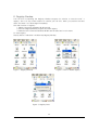
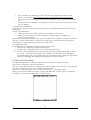
2.3 Scanning Barcode
To use the scanning function, complete the following steps:
1. If you have not already done so, remove the protective plastic film before using devices
equipped with a laser scanner.
Warning
Some AT570 come with laser scanners that scan using laser light. Never look directly into the
laser light or shine the laser light into the eyes.
2. Select Start > Programs > Scanner > AT1DScanner to open the scanning application. This
application runs in the background and only shows up as bar code icon in the system tray.
Figure 1. Scanning a bar code
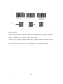
3. Aim the scanning beam at the center of the bar code.
• Position the device close to bar code when scanning small bar codes.
• Position it at a distance when scanning larger bar codes.
• The scanner stops scanning after you release the key or after five (5) seconds.
Figure 2. Scanning Beam Positions
Correct Scanning Position
1D
2D
Incorrect Scanning Position
48
AT570 Reference Guide
1D
2D
Wrong ways to san barcode
4. Press the Right or Left <Scan> key. The scanner scans as long as you hold the key or for
five (5) seconds.
5. Upon reading a bar code, the device beeps and the vibrates until the trigger is released or
after five (5)
seconds. The beep tone and Vibrates indicate a good read.
*If the bar code scan failed, adjust the reading angle or distance. Make sure that the scanning
beam scans across all bars of the bar code.
6. The bar code data is entered in the current application. Once a bar code is read
successfully, the scanner turns off automatically.
49
Quick Reference Guide
3. Wireless LAN
The AT-570 is versatile mobile computer that you can add to your wireless LAN. It has an
internal 802.11 b/g radio to transfer data using wireless communications. This section of the
manual assumes that you have already set up your wireless communications network
including access points.
Your AT-570 supports TCP/IP network protocols. In a TCP/IP network, the AT-570
communicates with a host computer directly using TCP/IP. The access point acts a bridge to
allow communications in wireless networks.
3.1 Power on Wireless LAN
The default of Wireless LAN was set with “ WLan off” when your AT-570 was manufactured
at the factory.
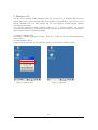
To make wireless LAN on:
Press FN key and Esc key at the same time, than you can see the following screen.
Figure 1. Wireless icon
Figure 2. Select AP
50
AT570 Reference Guide
After selecting “ WLan On” the LAN icon appears on the control bar.
Connecting your AT-570 to a network device:
Double tap LAN icon > tap Wireless Information.
Figure 3. Select AP
Select a network that your AT-570 has scanned in the list box, and tap Connect after
selecting the network, than the network will be connected to your AT-570.
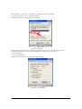
3.2 IP Information
To see IP Information:
Double-tap the LAN icon, and tap IP Information tap.
Figure 4. IP Information
51
Quick Reference Guide
3.3 Setting manually
You can also connect your AT-570 to a network with manual method in the Wireless
Properties.
To set wireless LAN in Wireless Properties:
Double tap WLAN icon > tap WLAN Tap > Input data > Tap “ OK”
Figure 5. Wireless Properties
3.4 Power Off Wireless Off
To make wireless LAN Off:
Press FN key and Esc key at the same time, and select WLAN Off
Figure 6. Wireless Off
52
AT570 Reference Guide
4. Bluetooth
Your AT-570 can optionally be built in with the Bluetooth Manager program to communicate
with wireless printer. In the Bluetooth Stack Service, your AT-570 only supports SPP (Serial
Printer Profile)
To make sure your bluethooth device, keep these following tips in your mind.
4.1 To enable Bluetooth
Bluetooth is not started by default after a clean-boot is performed. It is because of your
AT-570 retains the bluetooth state when a clean-boots are performed. For example, if
Bluetooth was enabled before a clean-boot, Your AT-570 boots up with the Bluetooth state
enabled and Bluetooth virtual COM ports registered. Reactivate the connections manually as
the system does not do them. If Bluetooth was disable before a clean boot was performed,
the AT-570 boots up with disabled.
To turn on Bluetooth:
Double tap My Device > Windows > Tap Bluetooth icon
4.2 Bluetooth Manager
Bluetooth Manager is a program that makes your AT-570 scan SPP device and connect to a
device that you want use in its scanning range.
After connecting your AT-570 to SPP device through Bluetooth Manager, the AT-570
supports Virtual Com Port (COM3) and sets up the Baud-rate as 9600 bps.
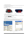
4.3 Connecting Bluetooth Printer(SPP)
BT-Manager is coded only for Hardware support to connect AT-570 to a Bluetooth Printer.
To start BT_Manager:
Tap Start > Program > Tap BT_Manager
Figure 1. Executing BT_Manager
53
Quick Reference Guide
Figure 2. Step-1 COM3,9600,Mode:1 Click “ Open”
Figure 3. Step-2 Scanning around Device
After the BT_Mmanager Scans Bluetooth
SSP device, the information of scanned
devise will be displayed on the screen.
Note: If the BT_manager has found out the printer you
want to use before the “ OK” massage appears, and
you want to stop scanning other printer, you can stop
scanning other printer to click the “ Scan Stop”
button.
Figure 4. Step-3 After scanning device
54
AT570 Reference Guide
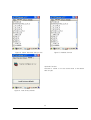
Connecting to a Bluetooth printer
1. Select a printer you want to use
Figure 5. Step-4 Selecting the Device
2. Input the pin-code number provided
from its manufacturing company.
3. Click the “ Connect” button
Figure 6. Step-5 Press the “ Connect button “ after inputting the pin code
55
Quick Reference Guide
4. If your PDA is connected to a
printer, you can see the connection
massage- “ CONNECT xxxxxxxxx”
5. Click the “ Mode Save” button to
save the connection status (refer to
“ Automatic Connection Restoration” )
Caution: the “ Mode Select” must be
set by 1.
Figure 7. Step-6 Press the “ Mode Save “ after Checking up connection
6. To test printing click the “ Test
Printing” button.
7. Click the “ Apply(Exit)” button to
close BT_manager.
Figure 8. Step-7 Apply(Exit) Click
Automatic Connection Restoration: Your AT-570 will get to be connected to a printer after the
Step7. Make a mental note that BT-Manager is coded only for Hardware support to connect
your AT-570 to a printer. On this understanding you may know that AT-570 will restore the
former connection after the following case:
1. After you turn on your AT-570 to restart.
2. After you perform a reset or hardreset activity.
56
AT570 Reference Guide
Note: Use the BT_Manager, when you are under the following case:
1. To close BT_Manager after it is connected to a printer.
2. If you don’ t want to use the printer anymore, and stop to support power to the
Bluetooth chip modulated in AT-570 to save more power.
3. If you want to connect your AT-570 to another printer.
4.4 Reference for Application Developer
Check up the connection of AT570 to a Bluetooth Printer after the step7
To control Bluetooth Printer with the user’ s application, you should set your AT-570 as
COM3 and 9600bps rate.
Application developer, if they need to make the program to control the Bluetooth printer,
they must follow the below steps:
1. Make your AT-570 connected to a Bluetooth Printer through the BT_Manager. the
BT_Manager program is only for hardware connection support, so you will never use it
as far as the Bluetooth Printer is not changed.
2. If you make program with the EVC++ Tool, you need to set the Port as COM3 and
Baud rate as 9600bps.
Ex ) EVC++ Source
-. Open ( Windows API CreateFile Function)
g_BT_Handle = CreateFile(_T("COM3:"),
GENERIC_READ | GENERIC_WRITE,
0,
NULL,
OPEN_EXISTING,
FILE_ATTRIBUTE_NORMAL,
NULL
);
dcb.BaudRate
dcb.StopBits
dcb.ByteSize
= CBR_9600;
= ONESTOPBIT;
= 8;
-. Printing data from AT-570 (Windows API WriteFile Function)
Make the Bluetooth Printer print the data from AT-570 to use the Writefile function.
-. Reading data from printer (Windows API ReadFile Function)
Make AT-570 read the data from the Bluetooth Printer to use the ReadFile Function
Ex ) Bluetooth Data : MSR Data Etc…
Note: If there is some problem with your bluetooth printer when you use your program which is
coded with the Library Function provided from the printer manufacturing company, you
should contact someone working in that company for further information
Checking up the communication between the Bluetooth printer and the demo program
Try to type data with keyboard in the program that is displayed on the screen (Figure 18), or
the demo program will transmit your data to the Bluetooth printer, than the printer will print the
data. It is no matter to try this test even after turning on your AT-570 when its power is off.
57
Quick Reference Guide
4.5 Disconnecting Bluetooth Printer(SPP) from AT-570
Use the BT_Manager to disconnect the Bluetooth printer from your AT-570, when you are
under the following case:
1. To close BT_Manager after it is connected to a printer.
2. If you don’ t want to use the printer anymore, and stop to support power to the
Bluetooth chip modulated in AT-570 to save more power.
3. If you want to connect your AT-570 to another printer.
Start > Program > Tap BT_Manager
To disconnect bluetooth printer from
AT-570:
1. Execute BT_Manager.
2. Click the “ Open” button.
3. Select 9600bps, and select 1
in the Mode Select box.
4. Click the DisConnect button.
Figure 9. Click BT_Manager
Figure 10. Step-1 Click COM3,9600,Mode:1 Open
Figure 11. Step-2 Click “ Disconect”
Note : you can connect your AT-570 to another printer after tapping the Disconnect button.
58
AT570 Reference Guide
5. To save more power, press
the “ Power Off” button.
Figure 12. Step-3 “ Power off” Click
Note : You should close the program after tapping the “ Power Off” button, therefore you can
use the program again anytime.
59
Quick Reference Guide
5. 13.56MHz ATID Multi (R/W)Reader
5.1 Optional Types
According to the installation method of RFID module, the AT-570 has 2 kinds of type
[Built-in type]
This kind of AT-570 is designed with a built-in RF13.56 module.
RF13.56
module
Figure 1. Figure built-in RF13.56 module
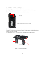
[Gun-typed]
This kind of AT-570 is designed like a gun (see the following figure), and RF13.56 module is
installed in the NO.3 RF reader.
To read data, put a tag in front of the NO.3 RF reader and press the NO.2 trigger.
2
3
1
Figure 2. Gun-typed RFID reader
60
AT570 Reference Guide
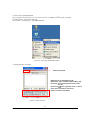
5.2 Executing ATIDMultiReader
1
This program only allows for AT-570 with a built in 13.56MHz RFID module optionally
To Read Mifare, ISO15693 RFID tag
Tap [Start] > [Programs] > [ATRFMultiReader]
Figure 3. Executing ATRFMultiReader
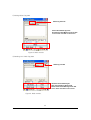
1) Reading Mifare Tag data
Mifare tag read tab
UID Read: Tap to Read Mifare tag ID.
Block Read: Tap to read block data of Mifare tag.
Increment: Tap to add registered value of data
to value.
Decrement: Subtract registered value of data to
value.
Clear: Erase read data on the screen.
Version: Firmware information.
Figure 4. Multi module.
61
Quick Reference Guide
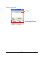
2) Writing Mifare Tag data
Mifare tag write tab
Write: Write Mifare tag block.
Block Read: Read Mifare tag block data.
Clear: Erase read data on the screen.
Figure 5. Multi module
3) Reading ISO 15693 Tag data
15693 tag read tab.
UID Read: Read 15693 tag ID.
Stop: Stop Reading 15693 tag ID.
Block Read: Read 15693 tag block data.
Clear: Erase read data on the screen.
Figure 6. Multi module.
62
AT570 Reference Guide
4) Writing ISO 15693 Tag data
15693 tag write
tab.
UID Read: Read 15693 tag ID.
Block Read: Read 15693 tag block data.
Clear: Erase read data on the screen.
Figure 7. ISO 15693 module
63
Quick Reference Guide
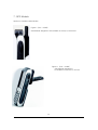
6. UHF 900Mhz(Read / Write) Reader
Figure 1. UHF Small Size
Figure 2. UHF Large Size
64
AT570 Reference Guide
6.1 UHF 900Mhz(Read / Write) program
This program is basically prepared to read and write RF ID tag through the Gen2 protocol.
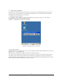
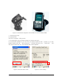
1) Executing Program
To execute UHF 900MHz(R/W) program, please keep the following description in your mind.
Figure 3. Executing UHF program
1. Double-click the UHF-DEMO program on the background screen.
2. Just wait the message -“Wait a second” appears, than UHF main menu will be
appeared.
3. You can also execute UHF to Tap Program > AT570UHF_net
2) Description for Main menu screen
[Multi Tag Read (Anti Collision)]: Tap to read
Multi-tag.
[Block Read/Write]: Tap to read Memory by Block in
the Memory Bank.
[One Tag Read]: Tap to read only one tag’s UID.
[Lock / Kill]: Tap to make tag’s memory locked/
unlocked or killed by Memory Bank.
[Setting]: Tap to confirm and adjust settings
Figure 4. UHF Main Menu
65
Quick Reference Guide
3) Reading Multi-tag
1.Select Gen2 protocol before you scan tags.
2.If you tap the [Start] button, the [Start] button will
be changed into [Stop] button and the reader tries
to read tags.
3.If you want to stop reading tags and bring back
the [Start] button again, tap the [stop] button.
4.The program counts the numbers of scanned tags,
and displays it in the “ Tag Count” box.
5.If you check the [Continue] box, the reader read
tags continuously, and the number reading UID will
increase.
6.Tap the [Clear] button to clear the data you
scanned.
7.Instead of the [Start] button, you can also use the
Fn4 Key, Left ScanKey, Right ScanKey on the PDA
when you scan tag.8. Tap [Save] button to save the
UID data displayed on the screen, than the data will
go into \Flash Disk\Currant time.txt Ex)
20071005102239.tx
Figure 5. Reading Multi-tag
4) Reading One Tag
1. Select Gen2 protocol before you scan a tag.
2. If you tap the [Start] button, the [Start] button
will be changed into [Stop] button and the reader
tries to read a tag.
3. If you want to stop reading a tag and bring back
the [Start] button again, tap the [stop] button.
4. If you want to read a tag continuously, check the
[Continue] box.
5. The program counts the times of scanned a tag,
and displays it in the “ Tag Count” box.
6. Tap the [Clear] button to clear the data you
scanned..
7. Instead of the [Start] button, you can use the Fn4
Key, Left ScanKey, Right ScanKey on the PDA when
you scan tag.
Figure 6. Reading One Tag
66
AT570 Reference Guide
5) Reading and Writing Block Data
Reading Block Data
1. Select bank type before you read block data.
2. Select the start memory and its Length you want
read.
3.Tap [Block Read] button to read block data, and
you can also use Fn1 key instead of [Block Read]
button.
4.The screen displays the block data you read.
5.It is impossible to access to the locked block
without access password.
Writing data in block
1. Select bank type before you write data in block
2. Select the start memory and write data.
3 Tap [Block Write] button to write data, and you
can also write data with Fn2 key instead of [Block
write] button.
4.If you succeed in writing data, the screen displays
the “ Success” message.
Figure 7. R/W Block Data
Note:
The error messages: When the memory that you give a test in writing data is in case of being
locked.
“Memory Locked” message: if you try to write data without password.
“Not Detect” message: if you try to write data with incorrect password.
The start memory must be selected from over “ 01” block, when you give a test in writing
data in block. It is because that the block located at from 00 to 01 is reserved, you can not
use it as your pleases.
6) Inputting the password
Inputting Access Password
1. Move to Block Read/Write screen, and select the “BankType” as “RESERVED”
2. Select 02 for the start memory.
3. Input 8 hexadecimal figures for “ AccessPassword”.
4. Press [Block Write] button.
5. If you succeed in inputting password, the screen displays the “ Success” message.
6. To make certain of the Access Password, Press [Block Read] after you set the “Start” and
“Length” by 02, and select the “BankType” as “RESERVED”
Inputting Kill Password
1. Move to Block Read/Write screen, and select the “BankType” as “RESERVED”
2. Select 00 for the Start memory.
3. Input 8 hexadecimal figures for “ killpassword” .
4. Press [Block Write] button.
5. If you succeed in inputting password, the screen displays the “ Success” message.
67
Quick Reference Guide
6. To make certain of the Kill Password, Press [Block Read] after you set the “Start” by 00
and set “Length” by 02, and select the “BankType” as “RESERVED”
The memory that has Access Password must be unlocked for changing Access Password, and
it needs Access Password to read and write the locked AccessPassword or KillPassword.
7)
Lock/UnLock
Locking memory
. 1. Check the MemoryBank on the CheckBox that
you want to make it locked.
2. Input the access password(8 hexadecimal
figures) in the Access_PWD box
3. Press the [Lock] button.
4. If you succeed in making the MamoryBank
locked, the “ Success” message appears on the
screen, but if you use incorrect password, the
“ Not Detect” message will appear.
1. Check the MemoryBank on the CheckBox
that you want to make it unlocked.
2. Input the access password (8 hexadecimal figures) in the
Access_PWD box.
3. Press the [Unlock] button
4. If you succeed in making the MamoryBank
unlocked, the “ Success” message appears on
the screen, but if you use incorrect password, the
“ Not Detect” message will appear.
Figure 8. Memory Locking
Killing memory
1. Input the kill password (8 hexadecimal figures) in the kill_PWD box.
2. Press [Kill] button.
3. If you succeed in making the MamoryBank killed, the “ Success” message appears on the
screen, but if you use incorrect password, the “ Not Detect” message will appear.
Caution
Make sure that you cannot use the Memory bank you killed again.
68
AT570 Reference Guide
8) Setting
Figure 8. Setting
1. [Protocol Ver.]: It shows the version of
modulated firmware, but it has no relation with
PDA Operating System.
2. [Hopping_Mode]: Hopping Mode of RFID
module.
Because every country has its own frequency
bandwidth, so the hopping mode cannot be
changed with any S/W.
3. [Scan Time]: The reader performs reading
activity to the end of selected time, and it
stops reading tag when the selected time goes
off. If the Scan Time is 0 (default=0), it means
that the reader runs unlimitedly before receiving
a stop-command.4. [Buzzer Switch]: Tap to
turn on or off Buzzer that makes sound when
the RFID reader succeeds in reading tag.
5. [Power Control]: Tap to control the output
power .
Power Value Min: 0 ~ Max28dbm
Default=0
The actual power value will be reduced as
much as you set the PowerValue.
ex) if PowerValue = 3, actual power value=
25dBm.
69
Quick Reference Guide
7. GPS Module
Options to install the GPS Module
Figure 1 (Port : COM6)
GPS Module designed to be installed on the top of the AT570
Figure 2 (Port : COM9)
GPS Module designed to
be installed on the rear of AT-570
70
AT570 Reference Guide
Figure 3. GPS Module designed to be installed on the Car Cradle(COM9)
7.1 Executing the GPS
To execute GPS:
Tap start > program > GPS_xxx.exe
7.2 Configuring the Port and Baud Setting for Executing the GPS
To use the GPS installed on your AT-570, you need to make the GPS’ s power on. For that,
please double-click the “ GPS_Power_Init “ -the EXE file that in the “ Flash Disk” . And
than tap the GPS EXE icon, the following GPS screen appears.
Figure 4. Executed GPS screen
Figure 5. Comm Setting
71
Quick Reference Guide
If you tap the Agree tap in the figure 5, the Comm Setting screen appears. For executing the
GPS, you need to configure the port and baud at first. Select the “ connect” on the
command bar, and select Serial Port(Comm Port) in the pop-up menu.And select these
settings.
GPS port: COM9(GPS_in.exe, GPS_Car.exe) or COM6(GPS_Top.exe)
Baud:
9600 bps
Figure 6. Comm Setting screen
Tap “ OK” after configuring Port and Baud
Figure 7. Com Port Setting
Figure 8. Baud Rate Setting
72
AT570 Reference Guide
7.3 Checking the GPS status
After tapping “ OK ” if the program is operated normally, you can see the red lamp (see the
○
1 in the figure 26) glittering.
The data received appears in the part of the ○
2 (but according to the reception status it takes
more or less time to access data.)
2
○
1
○
Figure 9. GPS Reception Status
Confirmation of receiving GPS data
1. Find an open place to check your GPS.
2. According to the actual environment, the time to receive data is different (about
3~10min)
3. After receiving GPS data once, it is more fast to receive GPS data than the first
attempt .
73
Quick Reference Guide
8. GSM/GPRS
8.1 Executing Phone UI
To start Phone UI Program:
Tap My Device > Flash disk> Phone_UI
Figure 1 Executing Phone_UI
8.2 Phone Screen
Figure 2 Phone Screen
74
AT570 Reference Guide
(1) Status Icons
Icon
Description
Receive Sensitivity Icon
Notice Icon for receiving phone
Notice Icon for receiving text massage
Indicator for Roaming service (Only for CDMA)
Dormant mode Icon (Only for CDMA)
Vibration mode Icon (GSM)
Data Communication state Icon (GSM)
Battery Status Icon
(2) Function Icons
Function
Icons
Description
Press this icon to refer to the whole telephone number listed in the PDA.
Press this icon to search the directory for a number.
Press this icon to manage your text massage.
Press this icon to use Dial-up Connection for connecting your phone to
RAS data communication.
(3) Having a phone
1) Press the telephone number you want to call.
2) You can adjust incorrect number and rewrite the number over again to press [CLR] button.
3) Press [SEND] button to have a phone call.
Note: If you press [SEND] button without inputting phone number, the phone number list
that you has called before appears on the screen.
4) Start to have a telephone call after connection.
- The dial tone comes out and you can call.
- The talk time will be displayed on the screen.
5) Press [END] button to finish communication.
(4) Receiving a phone
1) The bell rings and receiving massage appears when you receive a phone.
2) Press [SEND] button to start to have a phone.
3) The telephone will be disconnected when you press [END] button or the opposite person
presses the [END] button.
(5) The others (Only for GSM)
1) You can input the “ +” to press [*] button with long time.
2) You can input the “ ” -space character to press the [0] button with long time.
75
Quick Reference Guide
9. Using Camera
9.1 To use your Camera:
Tap start > Program > Camera
Figure 1. Executing Camera
Camera Screen
Delete File Button
Adjusting Brightness
Preview Window
Zooming button
Re-rotation Button
Preview Stop Button
Setting Viewing Effect
Resolution Setting Button
Capturing button
Preview Start Button
The number of stored files
Figure 2 Camera Screen
76
AT570 Reference Guide