1
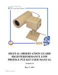
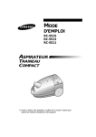
DOG WIRELESS REMOTE CAMERA
KIT MANUAL
Version 2.0
June 3, 2013
DWRC-Kit-v1_manual_v2.0
0
Table of Contents
DOG Wireless Remote Camera (DWRC) Kit Description .......................................................................... 3
Serial Numbers ......................................................................................................................................... 4
Charging the Battery ..................................................................................................................................... 4
Camera Unit Battery Removal.................................................................................................................. 4
Receiver Unit Battery Removal ................................................................................................................ 5
Battery Charger Operation ........................................................................................................................ 5
Mounting the Camera Unit ........................................................................................................................... 6
Attaching the Camera Unit to the Vest ..................................................................................................... 6
Standalone Mounting with Standard Tripod Mounts ............................................................................... 6
Using the Camera Unit ................................................................................................................................ 7
Antenna Attachment and Extension ......................................................................................................... 7
Powering the Camera Unit........................................................................................................................ 8
Using External Power ............................................................................................................................... 9
External Video Input............................................................................................................................... 10
Channel Selection ................................................................................................................................... 10
Enabling/Disabling the Microphone ....................................................................................................... 11
Using the Monitor Unit .............................................................................................................................. 11
Antenna Attachment and Extension ....................................................................................................... 11
Powering the Monitor Unit ..................................................................................................................... 13
Using External Power ............................................................................................................................. 13
External Video Input and Output ............................................................................................................ 14
Monitor Display Controls ....................................................................................................................... 15
Connecting the Headphones ................................................................................................................... 15
Channel Selection ................................................................................................................................... 16
Contact Info/Tech Support ......................................................................................................................... 16
Replacement Parts ...................................................................................................................................... 16
DWRC-Kit-v1_manual_v2.0
1
Table of Figures
Figure 1: DWRC kit...................................................................................................................................... 3
Figure 2: Serial Numbers on DWRC Transmitter and Receiver .................................................................. 4
Figure 3: Removing battery from the camera unit........................................................................................ 4
Figure 4: Removing battery from the monitor unit. ..................................................................................... 5
Figure 5: Charging a battery. ........................................................................................................................ 5
Figure 6: Attaching the malice clips to the camera unit for vest attachment. .............................................. 6
Figure 7: Standalone mounting options. ....................................................................................................... 7
Figure 8: Connecting an antenna to the Camera Unit................................................................................... 7
Figure 9: Connecting the antenna extension cable. ...................................................................................... 8
Figure 10: Camera Unit interfaces. ............................................................................................................... 9
Figure 11: Externally powering the Camera Unit......................................................................................... 9
Figure 12: External video input to the Camera Unit................................................................................... 10
Figure 13: Adapting the AV cable for either male or female BNC terminated coax cable. ....................... 10
Figure 14: Changing the Camera Unit channel. ......................................................................................... 11
Figure 15: Disabling the microphone. ........................................................................................................ 11
Figure 16: Connecting antenna to the Monitor Unit. .................................................................................. 12
Figure 17: Antenna extension hardware. .................................................................................................... 12
Figure 18: Connecting the antenna exension cable. ................................................................................... 12
Figure 19: Monitor Unit interfaces. ............................................................................................................ 13
Figure 20: Externally powering the Monitor Unit. ..................................................................................... 14
Figure 21: External video input and video/line audio output. .................................................................... 14
Figure 22: Adapting the AV cable for either male or female BNC terminated coax cable. ....................... 15
Figure 23: Display controls. ....................................................................................................................... 15
Figure 24: Connecting the Headphones ...................................................................................................... 15
Figure 25: Monitor channel selection. ........................................................................................................ 16
DWRC-Kit-v1_manual_v2.0
2
DOG Wireless Remote Camera (DWRC) Kit Description
The DOG Wireless Remote Camera (DWRC) Kit is a standalone kit that provides all the components
needed for remote observation of through-building or outdoor activities in bright or low light conditions.
The camera unit may be worn on a standard military style vest or set up standalone. The system provides
both video and audio recording, low light performance, covert infrared illumination, external power
capabilities, and video scrambling.
Each kit contains:
• 1 transmitter camera unit with IR illuminator
• 1 transmitter antenna
• 1 receiver unit with LCD display
• 1 high gain receiver antenna
• 1 replacement transmitter battery pack
• 1 replacement receiver battery pack
• 2 universal (90-270VAC) battery rechargers
• 2 universal (90-270VAC) power adapters
• 1 set of malice clips with screws
• 1 ear-bud headphone set
• 1 external AV RCA cable
• 1 set of SMA and BNC adapters
• 1 user manual
Figure 1 below shows the DWRC kit.
Figure 1: DWRC kit.
DWRC-Kit-v1_manual_v2.0
3
Serial Numbers
The serial number can be seen on the inside of the battery enclosure in both the DWRC camera and
DWRC monitor units.
Figure 2: Serial Numbers on DWRC Transmitter and Receiver
Charging the Battery
Camera Unit Battery Removal
Remove the retaining screw from the transmitter unit battery cover and slide the cover off. Grasp the
battery cable plug, pressing and holding the retaining clip to release it, and gently pull the plug free from
the connector. Lift the battery pack free from the battery compartment.
Figure 3: Removing battery from the camera unit.
DWRC-Kit-v1_manual_v2.0
4
Receiver Unit Battery Removal
Remove the retaining screw from the receiver unit battery cover and slide the cover off. Grasp the
battery cable plug, pressing and holding the retaining clip to release it, and gently pull the plug free from
the connector. Lift the battery pack free from the battery compartment.
Figure 4: Removing battery from the monitor unit.
Battery Charger Operation
Remove a battery charger as seen in the figure below from the kit. Plug the charger into an AC outlet and
connect the battery as seen below. When the charger light turns green, the battery is fully charged.
Figure 5: Charging a battery.
DWRC-Kit-v1_manual_v2.0
5
Mounting the Camera Unit
Attaching the Camera Unit to the Vest
Attach the two Malice clips to the back of the Camera unit, using two 8-32 x 1/4 pan-head screws to
secure each clip, as shown in the figure below. Slide the attached clips through the loops on the front of
the vest. Fold the clips at the center and insert the ends in the locking tabs to secure the Camera unit to
the vest.
Figure 6: Attaching the malice clips to the camera unit for vest attachment.
Standalone Mounting with Standard Tripod Mounts
The camera unit contains ¼”X20 tapped holes on three of its surfaces so that standard video camera
mounts can be used. Mount the camera by screwing the camera mount into the appropriate hole as shown
in the figure below.
DWRC-Kit-v1_manual_v2.0
6
Figure 7: Standalone mounting options.
Using the Camera Unit
As seen in Figure 7 below, all the camera unit interfaces for normal use are along the right side of the unit
as you look at the camera window. Push buttons are used to toggle the power and infrared illuminator,
while jacks are provided for external camera inputs and external power.
Antenna Attachment and Extension
Before powering up the Camera Unit please connect an antenna to it. Remove the short antenna from the
kit and connect it to the SMA connector on the top of the unit as shown in the figure below.
Figure 8: Connecting an antenna to the Camera Unit.
The antenna can be extended for vehicle or rooftop mounting using standard 50 ohm coax cable with
BNC connectors. Extensions over 50ft are not recommended. An antenna extension will require a
50ohm coax cable with BNC terminations to be supplied by the user, along with the two SMA to BNC
adapters and the short antenna from the DWRC kit as shown in the figure below. To extend the antenna
simply plug the SMA to BNC adapter into the Camera Unit antenna connector as shown. Then connect
the 50 ohm coax extension cable to the adapter and then plug the second BNC to SMA adapter on the
other end of the extension cable as shown. Finally, connect the short antenna to the SMA end of the
adapter as seen in the figure below.
DWRC-Kit-v1_manual_v2.0
7
Figure 9: Connecting the antenna extension cable.
Powering the Camera Unit
Make sure an antenna is connected to the unit first, and then push the button labeled “POWER” as seen in
the figure below. This will toggle the power on and off. The LED labeled P just below the button will
turn on to indicate that the power is on.
**CAUTION: MAKE SURE ANTENNA IS CONNECTED PRIOR TO POWERING UP THE
UNIT
**CAUTION: TURN OFF THE CAMERA UNIT WHEN IT IS NOT IN USE TO AVOID
DRAINING THE BATTERY.
Push the button labeled “ILLUMINATOR” as seen in the figure below. This will toggle the infrared
illuminator on and off. The LED labeled I just above the button will turn on to indicate that the
illuminator is on.
**CAUTION: TURN OFF THE ILLUMINATOR IF NOT NECESSARY TO EXTEND
BATTERY OPERATION.
DWRC-Kit-v1_manual_v2.0
8
Figure 10: Camera Unit interfaces.
Using External Power
If local AC power (110 or 220VAC) is available, then the Camera Unit can be powered using the
universal AC power adapter included in the kit. Simply plug the adapter into the AC outlet and connect
the jack to the “12VDC IN” jack as shown in the figure below.
Figure 11: Externally powering the Camera Unit.
DWRC-Kit-v1_manual_v2.0
9
External Video Input
An independently powered external video camera may be used with the Camera Unit. When the external
camera is connected it will override the built in camera and the external camera video will be transmitted
to the receiver. Plug the AV RCA cable from the kit as seen in the figure below, into the “VIDEO IN”
jack on the Camera Unit.
Figure 12: External video input to the Camera Unit.
If the external camera provides a 75ohm coax interface with BNC connectors, then the BNC adapters
from the kit can be used. Plug the appropriate BNC adapters from the kit to fit the external camera
interface as seen in the figure below.
Figure 13: Adapting the AV cable for either male or female BNC terminated coax cable.
Channel Selection
The channel can be changed by the user in order to prevent interference with another nearby DOG
Wireless Remote Camera set. The channel selector is inside the battery enclosure area as seen in the
figure below. A small arrow indicates the currently selected channel. Use a small Philips head
screwdriver to set the channel to the desired number as shown.
**CAUTION: MAKE SURE THAT THE CHANNEL SET ON THE MONITOR UNIT (RECEIVER)
MATCHES THE CHANNEL SET ON THE CAMERA UNIT (TRANSMITTER).
DWRC-Kit-v1_manual_v2.0
10
Figure 14: Changing the Camera Unit channel.
Enabling/Disabling the Microphone
To disable the microphone on the Camera Unit, access dip switch located right next to the channel
selector. With a small flathead screwdriver, flip the switch that is closest to the channel selector up as
shown in the figure below.
Figure 15: Disabling the microphone.
Using the Monitor Unit
As seen in Figure 13 below, all the camera unit interfaces for normal use are along the front side of the
unit just below the LCD screen. Push buttons are used to toggle the LCD monitor and the radio receiver,
while jacks are provided for external video input, video output, external power, and headphones.
Thumbwheels are provided for the control of brightness, color, and volume.
Antenna Attachment and Extension
Before powering up the Monitor Unit please connect an antenna to the Monitor Unit. Remove the long
antenna and the right angle BNC adapter from the kit. Connect the right angle BNC adapter to the BNC
antenna port on the left side of the Monitor Unit as shown in the figure below. Then connect the long
antenna into the right angle BNC adapter as shown.
DWRC-Kit-v1_manual_v2.0
11
Figure 16: Connecting antenna to the Monitor Unit.
The antenna can be extended for vehicle or rooftop mounting using standard 50 ohm coax cable with
BNC connectors. Extensions over 50ft are not recommended. An antenna extension will require a
50ohm coax cable with BNC terminations to be supplied by the user, along with the BNC barrel adapter
and long antenna from the DWRC kit as shown in the figure below.
Figure 17: Antenna extension hardware.
To extend the antenna simply plug the coax extension cord into the BNC connector on the Monitor Unit
as shown below. Then connect the BNC barrel adapter to the BNC connector on the other end of the 50
ohm coax cable as shown below. The antenna now connects to the barrel connector as seen.
Figure 18: Connecting the antenna extension cable.
DWRC-Kit-v1_manual_v2.0
12
Powering the Monitor Unit
Make sure an antenna is connected to the unit first, and then push the buttons labeled “MONITOR
POWER” and “RECEIVER POWER” as seen in the figure below. This will toggle the respective
functions on and off. LED’s next to each button will turn on to indicate that the function is active.
**CAUTION: MAKE SURE ANTENNA IS CONNECTED PRIOR TO POWERING UP THE
UNIT
**CAUTION: TURN OFF THE MONITOR UNIT WHEN IT IS NOT IN USE TO AVOID
DRAINING THE BATTERY.
Figure 19: Monitor Unit interfaces.
Using External Power
If local AC power (110 or 220VAC) is available, then the Monitor Unit can be powered using a universal
AC power adapter included in the kit. Simply plug the adapter into the AC outlet and connect the jack to
the “12VDC IN” jack on the side of the unit as shown in the figure below.
DWRC-Kit-v1_manual_v2.0
13
Figure 20: Externally powering the Monitor Unit.
External Video Input and Output
An independently powered external video camera may be viewed with the Monitor Unit. When the
external camera is connected it will override the transmitted video signal and the external camera video
will be displayed. Plug the AV RCA cable from the kit as seen in the figure below, into the “A/V
VIDEO IN” jack on the Monitor Unit.
The Monitor Unit can also provide video and line audio output to an external source such as an S4 Tech
DOG DVR or other external device. Simply plug the AV RCA cable into the “A/V VIDEO OUT” jack
and connect either or both the video and audio RCA’s to the external device.
Figure 21: External video input and video/line audio output.
If the external video device provides a 75ohm coax interface with BNC connectors, then the BNC
adapters from the kit can be used. Plug the appropriate BNC adapters from the kit to fit the external
device interface as seen in the figure below.
DWRC-Kit-v1_manual_v2.0
14
Figure 22: Adapting the AV cable for either male or female BNC terminated coax cable.
Monitor Display Controls
The brightness, color, and headset volume are all adjustable via the thumbwheel controls on the lower left
side of the Monitor Unit as seen in the figure below. Simply turn each thumbwheel to change the
appropriate setting to the desired level.
Figure 23: Display controls.
Connecting the Headphones
The ear-bud headphones plug into the headphone jack on Monitor Unit as seen in the figure below.
Figure 24: Connecting the Headphones
DWRC-Kit-v1_manual_v2.0
15
Channel Selection
The channel can be changed by the user in order to prevent interference with another nearby DOG
Wireless Remote Camera set. The channel selector is inside the battery enclosure area as seen in the
figure below. A small arrow indicates the currently selected channel. Use a small Philips head
screwdriver to set the channel to the desired number as shown
**CAUTION: MAKE SURE THAT THE CHANNEL SET ON THE MONITOR UNIT (RECEIVER)
MATCHES THE CHANNEL SET ON THE CAMERA UNIT (TRANSMITTER).
Figure 25: Monitor channel selection.
Contact Info/Tech Support
For questions or support please see our website at: www.bcfsolutions.net or contact:
[email protected], 703-956-9088.
For user manual or other technical downloads go to the customer tab on the website and login with the
following: user: customer password: 2004-S4Tech
Replacement Parts
The following replacement parts may be ordered for the S4 Tech Wireless Remote Camera Kit. Credit
card orders are accepted. Please contact S4 for order information.
Part No.
DWRC-CU
DWRC-MU
DWRC-CU-BA
DWRC-MU-BA
DWRC-BC
DWRC-CU-AN
DWRC-MU-AN
DWRC-AC
DWRC-BNC-S
DWRC-MC-S
Description
Camera Unit
Monitor Unit
Camera Unit replacement battery.
Monitor Unit replacement battery.
Battery charger.
Camera Unit antenna.
Monitor Unit antenna.
A/C adapter
BNC adapter set
Malice clip and screw set.
Cost USD
TBD
TBD
TBD
TBD
TBD
TBD
TBD
TBD
TBD
TBD
* Please contact S4 Tech for
pricing.
DWRC-Kit-v1_manual_v2.0
16