1
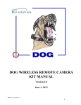
DIGITAL OBSERVATION GUARD
MINI-DOME PTZ KIT USER MANUAL
Version 1.0
June 17, 2013
Mini-dome-v1_manual-v1.0
0
Table of Contents
Mini-Dome PTZ Kit Description.................................................................................................................. 2
Mini-Dome PTZ Unit Basic Operation ........................................................................................................ 4
Mounting the Mini-Dome PTZ Units ........................................................................................................... 5
Wall or Pole Mounting the Mini-Dome PTZ Unit ................................................................................... 5
Ceiling Mounting the Mini-Dome PTZ Unit ............................................................................................ 7
Connecting the Mini-Dome PTZ Cable Assembly....................................................................................... 9
Connecting the Mini-Dome PTZ to the Current Model DOG .................................................................... 11
Connecting the PTZ data cable to the DVR on the Current Model DOG .............................................. 12
Connecting the Mini-Dome PTZ to an Older Model DOG ........................................................................ 12
Connecting the PT cable to the DVR on an Older Model DOG ............................................................ 13
Software Configuration .............................................................................................................................. 16
Mini-Dome PTZ Software Configuration .............................................................................................. 17
Troubleshooting .......................................................................................................................................... 18
Contact Info/Tech Support ......................................................................................................................... 19
Replacement Parts ...................................................................................................................................... 19
Table of Figures
Figure 1: Mini-Dome PTZ Kit Decal ........................................................................................................... 2
Figure 2: Mini-Dome PTZ Kit with Military Grade Case ............................................................................ 2
Figure 3: Mini-Dome PTZ unit with accessories ......................................................................................... 3
Figure 4: Mini-Dome PTZ Unit Channel ID Number .................................................................................. 4
Figure 5: Mounting directly to a wall ........................................................................................................... 5
Figure 6: Pole Mount Using the Wide-Range Straps Provided in the Kit .................................................... 6
Figure 7: Ceiling Mount Components .......................................................................................................... 7
Figure 8: Wall Mount Adapter Removal ...................................................................................................... 7
Figure 9: Position the Ceiling Mount Adapter Plate and Insert the screws through the plate ...................... 8
Figure 10: Tighten the screws completing the assembly .............................................................................. 8
Figure 11: Screw the Mini-Dome PTZ Unit to the ceiling ........................................................................... 9
Figure 12: Connecting the Cable Assembly to the Mini-Dome PTZ power/data cable ............................... 9
Figure 13: Connecting the Cable Assembly to the Mini-Dome PTZ video cable ...................................... 10
Figure 14: Connecting the Cable Assembly to the Remote Module .......................................................... 11
Figure 15: Mini-Dome PTZ Unit Connection Diagram on the Current Model DOG ................................ 11
Figure 16: Connecting the PTZ Cable at the VPD and DVR on the Current Model DOG ........................ 12
Figure 17: Mini-Dome PTZ Unit Connection Diagram on an Older Model DOG .................................... 13
Figure 18: DOG PTZ Cable ........................................................................................................................ 13
Figure 19: Remove Terminal Blocks from DVR on an Older Model DOG .............................................. 14
Figure 20: Installing the PTZ Cable Wire Terminals ................................................................................. 14
Figure 21: Tightening the Terminal Connections ....................................................................................... 15
Figure 22: Connecting the PTZ Cable at the VPD and DVR on an Older Model DOG ............................ 15
Figure 23: Channel and Dome Select Buttons and Screen ......................................................................... 16
Figure 24: Dome Control Buttons .............................................................................................................. 16
Mini-dome-v1_manual-v1.0
1
Mini-Dome PTZ Kit Description
The Mini-Dome PTZ Kit is an accessory kit for installation on the DOG Base Kit. Each Mini-Dome PTZ
Kit consists of two Mini-Dome PTZ units with cables and associated hardware. Each case can be
identified by a decal just above the handle as shown in Figure 1. The “DM” stands for DOG Mini-Dome
PTZ and is followed by the kit serial number.
Figure 1: Mini-Dome PTZ Kit Decal
Each Mini-Dome PTZ case contains 2 Mini-Dome PTZ Units, 2 Remote Modules, 2 cable assemblies, 2
ceiling mount adapters, and associated accessories. The Mini-Dome PTZ Units are capable of providing
720 degrees of horizontal (pan) motion and 90 degrees of vertical (tilt) motion. The units can be either
wall-mounted, ceiling mounted, or pole-mounted using the wide-range mounting straps (provided in the
kit) if necessary. Each Mini-Dome PTZ Unit has a channel ID reference number from 1 to 4 for
matching with the DOG Base Station. An example of a Mini-Dome PTZ Kit and associated hardware is
shown in Figure 2 below.
Figure 2: Mini-Dome PTZ Kit with Military Grade Case
Mini-dome-v1_manual-v1.0
2
One Mini-Dome PTZ unit with associated accessories is shown in Figure 3. Each of the two Mini-Dome
PTZ units in the case includes the following components:
•
•
•
•
•
•
•
1 Mini-Dome PTZ
1 Remote Module
1 Cable Assembly
2 wide-range mounting straps
1 Ceiling Mount Adapter
1 Allen wrench
Screws and connection hardware
Figure 3: Mini-Dome PTZ unit with accessories
Mini-dome-v1_manual-v1.0
3
Mini-Dome PTZ Unit Basic Operation
Each Mini-Dome PTZ Unit draws its power and data commands from, and transmits its video to, the
DOG Base Station VDP through the included Remote Module. The Mini-Dome PTZ unit can be placed
up to 750-ft from the DOG Base Station, using CAT-5 cable with no external power source required. The
Mini-Dome PTZ Channel ID (number 1-4) is indicated by a decal on the rear of the unit as seen in Figure
4 below and must be connected to the corresponding channel on the Base Station VPD and DVR. *
Make sure to keep track of the channel number of each Mini-Dome PTZ Unit.
Figure 4: Mini-Dome PTZ Unit Channel ID Number
To operate the Mini-Dome PTZ Unit, the user simply selects the channel of the camera from the buttons
on the front of the Base Station DVR and then pushes the Dome button on the DVR. This brings up an
on-screen message which indicates that the pan-tilt arrow buttons on the DVR are active. At this point,
pushing the arrow buttons moves the camera as indicated by the arrow buttons. Details of the Mini-Dome
PTZ unit setup and operation are provided in the following sections.
Mini-dome-v1_manual-v1.0
4
Mounting the Mini-Dome PTZ Units
Wall or Pole Mounting the Mini-Dome PTZ Unit
Wall or pole mounting can be accomplished using the Wall Mount Adapter attached to the Mini-Dome
PTZ as shipped in the kit. For a sturdy wall mount, position the Mini-Dome PTZ/Wall Mount Adapter
assembly against the wall and screw into the surface of the wall using large wood or sheet metal screws
(not included) through the mounting holes in the wall mount bracket as shown in Figure 5, making sure
that it is firmly mounted. Cement walls will require the appropriate cement anchors and pre-drilled holes.
*This operation requires two people*
Figure 5: Mounting directly to a wall
Mini-dome-v1_manual-v1.0
5
For a pole mount, screws may be driven into the pole in a similar manner as the sturdy wall mount. If
this is not possible or practical, the included wide-range stainless steel straps are wrapped around the wall
mount adapter and pole and tightened as shown Figure 6.
*This operation requires two people*
Figure 6: Pole Mount Using the Wide-Range Straps Provided in the Kit
Record the channel number and location of the installed Mini-Dome PTZ Unit for reference when using
the DOG Base Station to select and operate the unit.
Mini-dome-v1_manual-v1.0
6
Ceiling Mounting the Mini-Dome PTZ Unit
Ceiling mounting the Mini-Dome PTZ Unit requires the removal of the attached Wall Mount Adapter and
the attachment of one of the included Ceiling Mount Adapter Plates. The necessary Ceiling Mount
components are shown in Figure 7.
Figure 7: Ceiling Mount Components
Referring to Figure 8, use the included Allen key to remove the four hex cap-head screws which hold the
Wall Mount Adapter to the Mini-Dome PTZ, then remove the Wall Mount Adapter and store it (along
with the cap-head screws) for potential future use. Remove one of the Ceiling Mount Adapter Plates and
screw kits (bag labeled CM) from the case.
Figure 8: Wall Mount Adapter Removal
Mini-dome-v1_manual-v1.0
7
Referring to Figure 9, align the plate’s four inner mounting holes with the four threaded holes in the
Mini-Dome PTZ base and insert the four machine screws from the CM kit bag. Using a flathead
screwdriver, tighten the screws securely but do not over-tighten. The completed assembly is shown in
Figure 10.
Figure 9: Position the Ceiling Mount Adapter Plate and Insert the screws through the plate
Figure 10: Tighten the screws completing the assembly
Mini-dome-v1_manual-v1.0
8
Referring to Figure 11, place the completed Mini-Dome PTZ ceiling mount assembly in the desired
position on the ceiling. For wooden or compatible soft material structures, the wood screws provided in
the CM kit bag may be used to fasten the assembly to the ceiling. Using the four wood screws provided,
place a screw in each of the four surface mounting holes and drive them in using a Phillips screwdriver.
Make sure the mounted unit is securely attached. Cement ceilings will require the appropriate cement
anchors and pre-drilled holes.
*This operation requires two people*
Figure 11: Screw the Mini-Dome PTZ Unit to the ceiling
Connecting the Mini-Dome PTZ Cable Assembly
The Mini-Dome PTZ Cable Assembly is used to connect the Mini-Dome PTZ Unit to the Remote
Module, which provides the interface to the DOG’s CAT-5 infrastructure. Referring to Figure 12, insert
the four-pin plug at one end of the Cable Assembly into the four-pin socket on the Mini-Dome PTZ unit
power/data cable, being careful to match the alignment between the plug and the socket. Twist the cover
on the plug to lock it in place.
Figure 12: Connecting the Cable Assembly to the Mini-Dome PTZ power/data cable
Mini-dome-v1_manual-v1.0
9
Referring to Figure 13, insert the BNC connector at the same end of the Cable Assembly into the BNC
connector on the Mini-Dome PTZ Unit video cable, and twist the cover to lock it in place.
Figure 13: Connecting the Cable Assembly to the Mini-Dome PTZ video cable
Once the cables are connected, use a wire tie (or cord or tape) to secure the cables against the pole,
located below the mounting bracket, for strain relief. For a wall mount, the cables can be wire-tied to the
lower section of the mounting bracket itself.
Connect the other end of the Cable Assembly to the corresponding connectors on the Remote Module as
shown in Figure 14.
Mini-dome-v1_manual-v1.0
10
Figure 14: Connecting the Cable Assembly to the Remote Module
Connecting the Mini-Dome PTZ to the Current Model DOG
Connecting the Mini-Dome PTZ unit to the base station consists of two steps: connecting the Mini-Dome
PTZ’s Remote Module to the corresponding channel on the DOG Base Station VPD using CAT-5 cables,
and connecting the VPD channels to the corresponding channels on the Base Station DVR with the coax
patch cords supplied in the DOG Base Kit. The Mini-Dome PTZ Unit channel IDs are provided on a
decal at the back of the unit as seen in Figure 4. Figure 15 shows the described connections with all
channel numbers for the current model DOG, which includes an I/O board enhancement on the back of
the DVR. Even if only one or several Mini-Dome PTZ Units are employed, the channel numbers should
always match up as shown.
Figure 15: Mini-Dome PTZ Unit Connection Diagram on the Current Model DOG
Mini-dome-v1_manual-v1.0
11
Connecting the PTZ data cable to the DVR on the Current Model DOG
A short CAT-5 jumper cable is supplied with each Mini-Dome PTZ Kit case. This cable allows the DVR
RS-485 data port on the I/O board enhancement to be connected to the PTZ port on the VPD unit. The
cable connects between the S4-Tech DVR I/O enhancement board’s RJ-45 PTZ connector and the RJ-45
PTZ connector on the VPD, as shown in Figure 16.
Figure 16: Connecting the PTZ Cable at the VPD and DVR on the Current Model DOG
Connecting the Mini-Dome PTZ to an Older Model DOG
Connecting the Mini-Dome PTZ unit to the base station consists of two steps: connecting the Mini-Dome
PTZ’s Remote Module to the corresponding channel on the DOG Base Station VPD using CAT-5 cables,
and connecting the VPD channels to the corresponding channels on the Base Station DVR with the coax
patch cords supplied in the DOG Base Kit. The Mini-Dome PTZ Unit channel IDs are provided on a
decal at the back of the unit as seen in Figure 4. Figure 17shows the described connections with all
channel numbers for an older model DOG, which does not have the I/O board enhancement on the back
of the DVR. Even if only one or several Mini-Dome PTZ Units are employed, the channel numbers
should always match up as shown.
Mini-dome-v1_manual-v1.0
12
Figure 17: Mini-Dome PTZ Unit Connection Diagram on an Older Model DOG
Connecting the PT cable to the DVR on an Older Model DOG
A DOG PTZ cable is supplied with each Mini-Dome PTZ Kit case. This cable allows the DVR RS-485
data port to be connected to the PTZ port on the VPD unit. The cable, as seen below, is a CAT-5 patch
cord with an RJ-45 connector on one end and two wire terminals on the other end. The wire terminals are
color-coded with RED indicating the RS-485 D+ signal and BLACK indicating the RS-485 D- signal.
Figure 18: DOG PTZ Cable
Remove the two green terminal blocks on the back of the DVR unit, which are connected to the DOG
Alarm Box cable as seen in the figure below. Disconnect the RJ-45 connector on the Alarm Button Box
cable from the back of the Alarm Button Box, and then pry the terminal blocks out with your fingers or
with the help of a small screwdriver.
Mini-dome-v1_manual-v1.0
13
Figure 19: Remove Terminal Blocks from DVR on an Older Model DOG
Without disconnecting the Alarm Box cable from the terminal blocks, lay the bottom terminal block flat
and plug in the wire terminals from the supplied PTZ cable. As shown in the figure below, the PTZ cable
red terminal goes into the D+ slot on the lower terminal block and the PTZ cable black terminal goes into
the D- slot.
Figure 20: Installing the PTZ Cable Wire Terminals
Use a small jeweler’s screwdriver or the one supplied in the DOG Base Kit to tighten down the
connections in the terminal block as shown below. Gently pull on the PTZ cable to ensure secure
connection to terminal block.
Mini-dome-v1_manual-v1.0
14
Figure 21: Tightening the Terminal Connections
Now plug the terminal blocks back into the DVR as shown below. Plug the Alarm Button Box cable
back into the Alarm Button Box. Plug the RJ-45 connector on the other end of the PTZ cable into the
PTZ Port of the VPD unit as shown.
Figure 22: Connecting the PTZ Cable at the VPD and DVR on an Older Model DOG
Mini-dome-v1_manual-v1.0
15
Software Configuration
In order to control the Mini-Dome PTZ Unit from the DOG Base Station DVR, the desired video channel
is selected by pressing the associated channel button on the bottom left side of the DVR as shown below.
Once the full screen view of the selected channel appears on the monitor, press the DOME button to get
the Dome Control Hint screen as shown below.
Figure 23: Channel and Dome Select Buttons and Screen
The horizontal and vertical arrow buttons (shown below) will cause the Mini-Dome PTZ Unit to pan and
tilt respectively. The MENU/SEARCH (Zoom In/Out) buttons are used to adjust the PTZ camera lens
zoom level and the SEQ/FREEZE (Focus Near/Far) buttons are used to adjust the PTZ camera lens focus
setting. Pressing the channel 2 button on the left side will cause the menu to disappear but the buttons
will continue to function. Pressing the ESC button will cancel the Dome Control function and return the
DVR to normal mode.
Figure 24: Dome Control Buttons
Mini-dome-v1_manual-v1.0
16
The Base Station DVR unit is pre-configured with the proper pan-tilt settings for each channel. If the
software configuration gets corrupted or changed, the following settings should be used. These settings
are reached through the main menu which is entered by pushing the MENU button.
Mini-Dome PTZ Software Configuration
Menu-System Setup – RS485 Setup
1 Unit ID
224
2 Baud Rate 2400
3 Bits
8
4 Stop
1
5 Parity
None
Menu-Camera Setup (* for each channel 1-4)
1 Camera Select
CH1
2 Dome Protocol
PELCO D
3 Dome ID
1 (*same as selected channel above)
4 Covert
No
5 Termination
Yes
Mini-dome-v1_manual-v1.0
17
Troubleshooting
1. The Mini-Dome PTZ Unit stops during a motion. Let go and then push the arrow button again
and the unit should resume movement.
2. The Mini-Dome PTZ Unit does not move.
• Make sure that the selected channel matches the Mini-Dome PTZ Unit channel ID and that
all connections to the VPD and DVR also match the channel number.
• Make sure that the supplied PTZ cable has been connected both on the VPD and the
terminal strips on the back of the DVR unit.
• Make sure that the red and black terminals of the PTZ cable are installed into the right
slots of the terminal block (red to D+ and black to D-).
• Make sure that Mini-Dome PTZ Unit is plugged into the Remote Module through the side
connector.
• Make sure the Mini-Dome PTZ software configuration is correct in the DVR. See MiniDome PTZ Software Configuration Settings section of this manual.
3. The channel ID decal has come off and I don’t know the channel number of the Mini-Dome
PTZ Unit. Plug the Mini-Dome PTZ Unit CAT-5 cable into each channel of the VPD and select
each channel on the DVR using the Dome Control function until the unit responds. Mark the
Mini-Dome PTZ Unit with the correct Channel ID for reference.
4. The Mini-Dome PTZ video does not display on the monitor.
•
•
Make sure that the visible camera is selected by pressing the DVR’s MODE button while in
Dome Control.
Make sure that the coax patch cable is connected between the DVR and the VPD.
Mini-dome-v1_manual-v1.0
18
Contact Info/Tech Support
For questions or support please see our website at: www.bcfsolutions.net or contact:
[email protected], 703-956-9088.
For user manual or other technical downloads go to the customer tab on the website and login with the
following: user: customer password: 2004-S4Tech
Replacement Parts
The following replacement parts may be ordered for the DOG Mini-Dome PTZ Kit. Credit card orders
are accepted. Please contact S4 for order information.
Part No.
Description
Cost USD
TBD
Mini-Dome PTZ Unit with associated cables and hardware TBD
DP-CA-PTZ PTZ Cable assembly
TBD
TBD
Ceiling adapter plate
TBD
TBD
TBD
TBD
Optional military grade heavy duty transport case.
TBD
* Prices are as of TBD and are subject to change based on availability and material costs.
Mini-dome-v1_manual-v1.0
19