1
TC-6000 Series Expansion Modules
User’s Manual
First Edition, July 2014
www.moxa.com/product
© 2014 Moxa Inc. All rights reserved.
TC-6000 Series Expansion Modules User’s
Manual
The software described in this manual is furnished under a license agreement and may be used only in accordance with
the terms of that agreement.
Copyright Notice
© 2014 Moxa Inc., All rights reserved.
Trademarks
The MOXA logo is a registered trademark of Moxa Inc.
All other trademarks or registered marks in this manual belong to their respective manufacturers.
Disclaimer
Information in this document is subject to change without notice and does not represent a commitment on the part of
Moxa.
Moxa provides this document as is, without warranty of any kind, either expressed or implied, including, but not limited
to, its particular purpose. Moxa reserves the right to make improvements and/or changes to this manual, or to the
products and/or the programs described in this manual, at any time.
Information provided in this manual is intended to be accurate and reliable. However, Moxa assumes no responsibility for
its use, or for any infringements on the rights of third parties that may result from its use.
This product might include unintentional technical or typographical errors. Changes are periodically made to the
information herein to correct such errors, and these changes are incorporated into new editions of the publication.
Technical Support Contact Information
www.moxa.com/support
Moxa Americas
Moxa China (Shanghai office)
Toll-free: 1-888-669-2872
Toll-free: 800-820-5036
Tel:
+1-714-528-6777
Tel:
+86-21-5258-9955
Fax:
+1-714-528-6778
Fax:
+86-21-5258-5505
Moxa Europe
Moxa Asia-Pacific
Tel:
+49-89-3 70 03 99-0
Tel:
+886-2-8919-1230
Fax:
+49-89-3 70 03 99-99
Fax:
+886-2-8919-1231
Table of Contents
1.
Introduction ...................................................................................................................................... 1-1
Overview ........................................................................................................................................... 1-2
Package Checklist ............................................................................................................................... 1-2
Available Modules ............................................................................................................................... 1-2
TC-6000 Series Module Specifications ................................................................................................... 1-3
TC-DK10-T/TC-DK20-T Specifications ............................................................................................ 1-3
TC-SP04-DB44-T Specifications ..................................................................................................... 1-3
TC-CP02-DB-T Specifications ........................................................................................................ 1-3
TC-SW04-M12-4P-T/TC-SW04-M12-8P-T Specifications.................................................................... 1-4
TC-SATA-T Specifications (Available on Request)............................................................................. 1-4
2.
Hardware Introduction...................................................................................................................... 2-1
Appearance........................................................................................................................................ 2-2
TC-SP04-DB44-T ......................................................................................................................... 2-2
TC-CP02-DB-T ............................................................................................................................ 2-2
TC-DK10-T/TC-DK20-T ................................................................................................................ 2-2
TC-SW04-M12-4P-T/TC-SW04-M12-8P-T........................................................................................ 2-3
TC-SATA-T ................................................................................................................................. 2-3
Dimensions ........................................................................................................................................ 2-4
3.
Hardware Connection Description ..................................................................................................... 3-1
Installing the TC-6000 Series Expansion Modules.................................................................................... 3-2
Connecting Data Transmission Cables ................................................................................................... 3-3
TC-SP04-DB44-T Serial Port Module .............................................................................................. 3-3
TC-CP02-DB-T CAN Bus Module .................................................................................................... 3-4
TC-SW04-M12-4P-T/TC-SW04-M12-8P-T Switch Module .................................................................. 3-5
Installing Cellular Modules on the TC-DK10-T and TC-DK20-T .................................................................. 3-5
Installing a Cellular Module ........................................................................................................... 3-6
Installing the SSD/HDD into the TC-SATA Module ................................................................................... 3-7
4.
Software Installation and Programming Guide ................................................................................. 4-1
Linux System Peripherals Programming Guide ........................................................................................ 4-2
Prerequisite for Installing Peripheral Modules .................................................................................. 4-2
TC-SP04-DB44-T: Serial Port ........................................................................................................ 4-3
TC-CP02-DB-T: CAN Bus Interface ................................................................................................ 4-6
TC-DK10-T/TC-DK20-T: mini PCIe Interface ................................................................................. 4-10
Windows System .............................................................................................................................. 4-12
TC-SP04-DB44-T: Driver Installation ........................................................................................... 4-12
TC-SP04-DB44-T: Configuring Serial Port Mode............................................................................. 4-13
TC-CP02-DB-T: Driver Installation ............................................................................................... 4-17
TC-CP02-DB-T CAN Module: Programming Guide .......................................................................... 4-19
TC-DK10-T/TC-DK20-T: Enabling/Disabling USB Socket Power........................................................ 4-21
1
1.
Introduction
TC-6000 expansion modules provide peripheral interfaces to TC-6000 series railway computers.
The following topics are covered in this chapter:
Overview
Package Checklist
Available Modules
TC-6000 Series Module Specifications
TC-DK10-T/TC-DK20-T Specifications
TC-SP04-DB44-T Specifications
TC-CP02-DB-T Specifications
TC-SW04-M12-4P-T/TC-SW04-M12-8P-T Specifications
TC-SATA-T Specifications (Available on Request)
TC-6000 Series Expansion Modules
Introduction
Overview
TC-6000 series expansion modules may provide a 2.5 inch mass storage module with customizable
anti-vibration and temperature management features; four-port (without PoE) Gigabit- or megabit-Ethernet
switch modules, both with M12 connectors; a mini PCIe carrier module with four sockets; a serial module
supporting four software-selectable RS-232/422/485 interfaces over a single DB-44F connector (cable
adapter); or an optically isolated CAN module with two ports. These modules let system integrators and
administrators easily add additional storage capacity, Ethernet ports and/or bandwidth, as well as serial, PCIe,
and CAN interfaces to the TC-6000 series of train computers.
All of the TC-6000 modules are compliant with the essential sections of the EN 50155 Class TX standard,
guaranteeing the TC-6000 is a highly dependable computing platform specialized for a wide variety of on-board
railway applications.
Package Checklist
Each package ships with a single TC-6000 series expansion module.
NOTE: Please notify your sales representative if the module is damaged en route.
Available Modules
•
TC-DK10-T: 4 PCIe mini card slots with PCIe and USB interfaces on slot 1 and USB interfaces on slots 2, 3
and 4; 4 SIM card sockets; -40 to 70°C operating temperature (EN 50155 Class TX)
•
TC-DK20-T: 4 PCIe mini card slots with PCIe and USB interfaces, 4 SIM card sockets, -40 to 70°C operating
temperature (EN 50155 Class TX)
•
TC-SP04-DB44-T: 4 RS-232/422/485 serial interfaces over a single DB44 connector; cable sold
separately, -40 to 70°C operating temperature (EN 50155 Class TX)
•
TC-CP02-DB-T: 2 optically isolated CAN interfaces with DB9 connectors, -40 to 70°C operating
temperature (EN 50155 Class TX)
•
TC-SW04-M12-4P-T: 4-port Megabit Ethernet switch with M12 D-coded connectors, -40 to 70°C
operating temperature (EN 50155 Class TX)
•
TC-SW04-M12-8P-T: 4-port Gigabit Ethernet switch with M12 A-coded connectors, -40 to 70°C operating
temperature (EN 50155 Class TX)
•
TC-SATA-T (Available on request): 1-slot carrier module for 2.5-inch SATA mass storage drives, with
heater, vibration protections, accelerometer, and temperature sensor, -40 to 70°C operating temperature
(EN 50155 Class TX)
1-2
TC-6000 Series Expansion Modules
Introduction
TC-6000 Series Module Specifications
TC-DK10-T/TC-DK20-T Specifications
Mini PCIe Card
Interface: 4 sockets, total
• Socket 1 on both TC-DK10-T and TC-DK20-T: USB 2.0 /
PCIe V1.0
• Sockets 2, 3, and 4 on the TC-DK10-T: USB 2.0
• Sockets 2, 3, and 4 on the TC-DK20-T: USB 2.0 / PCIe V1.0
SIM Card Socket: 4 sockets reserved for cellular applications
Wireless Antenna Hole: 5 reserved for QMA antenna connectors
Physical Characteristics
Dimensions: 186 x 118 x 20 mm (7.32 x 4.65 x 0.79 in)
Weight: 220 g
Environmental Limits
Operating Temperature: -40 to 70°C (-40 to 158°F) (EN 50155 Class TX)
Storage Temperature: -40 to 85°C (-40 to 185°F)
Ambient Relative Humidity: 5 to 95% (non-condensing)
TC-SP04-DB44-T Specifications
Serial Port Interface
Serial Standards:
RS-232/422/485, software-selectable
Connector Type:
1 DB44 connector serving all 4 interfaces; special cable (CBL-M44M25x4-50 BK), required contact Moxa for
details)
Serial Communication Parameters
Data Bits: 5, 6, 7, 8
Stop Bits: 1, 1.5, 2
Parity: None, Even, Odd, Space, Mark
Flow Control: RTS/CTS, XON/XOFF, ADDC® (automatic data direction control) for RS-485
Baudrate: 50 bps to 921.6 Kbps (non-standard baudrates supported; see Chapter 4 for details)
Physical Characteristics
Dimensions: 186 x 118 x 20 mm (7.32 x 4.65 x 0.79 in)
Weight: 234 g
Environmental Limits
Operating Temperature: -40 to 70°C (-40 to 158°F) (EN 50155 Class TX)
Storage Temperature: -40 to 85°C (-40 to 185°F)
Ambient Relative Humidity: 5 to 95% (non-condensing)
TC-CP02-DB-T Specifications
CAN Interface
Interface:
2 optically isolated CAN 2.0 A/B ports
Signal: CAN-H, CAN-L
Isolation: 2 kV
Speed: 1 Mbps
Connector Type: DB9 male
Physical Characteristics
Dimensions: 186 x 118 x 20 mm (7.32 x 4.65 x 0.79 in)
Weight: 227 g
1-3
TC-6000 Series Expansion Modules
Introduction
Environmental Limits
Operating Temperature: -40 to 70°C (-40 to 158°F) (EN 50155 Class TX)
Storage Temperature: -40 to 85°C (-40 to 185°F)
Ambient Relative Humidity: 5 to 95% (non-condensing)
TC-SW04-M12-4P-T/TC-SW04-M12-8P-T Specifications
Ethernet Interface
Standard:
4 Ethernet M12 switch ports: auto-sensing 10/100 Mbps (TC-SW04-M12-4P-T) or 10/100/1000 Mbps
(TC-SW04-M12-8P-T)
Protection: 1.5 kV magnetic isolation protection
Connector Type: 4-pin M12 D-coded/8-pin M12 A-coded
Physical Characteristics
Dimensions: 186 x 118 x 20 mm (7.32 x 4.65 x 0.79 in)
Weight: 278 g
Environmental Limits
Operating Temperature: -40 to 70°C (-40 to 158°F) (EN 50155 Class TX)
Storage Temperature: -40 to 85°C (-40 to 185°F)
Ambient Relative Humidity: 5 to 95% (non-condensing)
TC-SATA-T Specifications (Available on Request)
SATA Interface
Description: Hot swappable, with 1 storage slot for 2.5 inch HDD or SSD, built-in vibration protection,
onboard accelerometer, temperature sensor, and Intelligent Heating Solution
LEDs: 4 total: 1 for drive activity, 1 for heater activity, and 2 user-configurable
Physical Characteristics
Weight: 393 g
Dimensions: 186 x 118 x 20 mm (7.32 x 4.65 x 0.79 in)
Environmental Limits
Operating Temperature: Wide Temp. Models: -40 to 70°C (-40 to 158°F) (EN 50155 Class TX)
Storage Temperature: -40 to 85°C (-40 to 185°F)
Ambient Relative Humidity: 5 to 95% (non-condensing)
1-4
2
2.
Hardware Introduction
The TC-6000 series expansion modules are designed to work with Moxa’s TC-6000 train computers. By
providing different modules with different connectors, the TC-6000 series offers convenient flexibility for users
who would like to easily build precise industrial solutions requiring a variety of communication interfaces.
The following topics are covered in this chapter:
Appearance
TC-SP04-DB44-T
TC-CP02-DB-T
TC-DK10-T/TC-DK20-T
TC-SW04-M12-4P-T/TC-SW04-M12-8P-T
TC-SATA-T
Dimensions
TC-6000 Series Expansion Modules
Hardware Introduction
Appearance
TC-SP04-DB44-T
TC-CP02-DB-T
TC-DK10-T/TC-DK20-T
Front
2-2
TC-6000 Series Expansion Modules
Hardware Introduction
Rear
TC-SW04-M12-4P-T/TC-SW04-M12-8P-T
TC-SATA-T
2-3
TC-6000 Series Expansion Modules
Hardware Introduction
Dimensions
All modules share the same dimensions.
2-4
3
3.
Hardware Connection Description
In this chapter, we show how to connect the embedded computers to the network and to various devices.
The following topics are covered in this chapter:
Installing the TC-6000 Series Expansion Modules
Connecting Data Transmission Cables
TC-SP04-DB44-T Serial Port Module
TC-CP02-DB-T CAN Bus Module
TC-SW04-M12-4P-T/TC-SW04-M12-8P-T Switch Module
Installing Cellular Modules on the TC-DK10-T and TC-DK20-T
Installing a Cellular Module
Installing the SSD/HDD into the TC-SATA Module
TC-6000 Series Expansion Modules
Hardware Connection Description
Installing the TC-6000 Series Expansion
Modules
The TC-6000 train computers come with four expansion module slots on the front panel. Refer to the following
figure for the location of these slots.
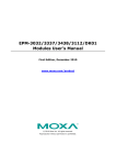
To insert the TC-6000 series expansion modules into the TC-6000 train computer, follow the steps below.
1. Loosen the thumbscrews and remove the coverplate.
2. Insert the module into the slot, being careful not to damage the card as you slide it into to the motherboard
connector. Once you have secured it into the slot, fasten the screws to lock it in.
3-2
TC-6000 Series Expansion Modules
NOTE
Hardware Connection Description
Note that the TC-SATA-T storage module can be inserted in slots 1, 2, or 3. However, slot 3 does not feature
the Intelligent Heating Solution (IHS). In addition, except for the TC-SATA-T storage module, other modules do
not support hot swap/plug function. Power off the TC-6000 computer before removing or inserting the
modules.
Connecting Data Transmission Cables
In this section we explain how to connect the TC-6000 series expansion modules to devices.
TC-SP04-DB44-T Serial Port Module
Use a serial cable to plug your serial device into the module’s serial port with DB44 connectors that can serve
4 serial interfaces and can be configured for RS-232, RS-422, or RS-485 communication by software. The pin
assignments are shown in the following figure and tables.
RS-232
Pin
Signal
Pin
Signal
Pin
Signal
Pin
Signal
1
TxD3
13
TxD0
25
DTR1
37
GND
2
RxD3
14
RxD0
26
DSR1
38
–
3
RTS3
15
RTS0
27
–
39
DCD1
4
–
16
CTS3
28
CTS0
40
–
5
TxD2
17
DTR3
29
DTR0
41
GND
6
RxD2
18
DSR3
30
DSR0
42
DCD0
7
RTS2
19
–
31
DCD3
43
–
8
–
20
CTS2
32
–
44
GND
9
TxD1
21
DTR2
33
GND
10
RxD1
22
DSR2
34
–
11
RTS1
23
–
35
DCD2
12
–
24
CTS1
36
–
Pin
Signal
Pin
Signal
Pin
Signal
RS-422 & 4-wire RS-485
Pin
Signal
1
RxD3(+)
13
RxD0(+)
25
RxD1(-)
37
GND
2
TxD3(+)
14
TxD0(+)
26
–
38
–
3
–
15
–
27
–
39
TxD1(-)
4
–
16
–
28
–
40
–
5
RxD2(+)
17
RxD3(-)
29
RxD0(-)
41
GND
6
TxD2(+)
18
–
30
–
42
TxD0(-)
7
–
19
–
31
TxD3(-)
43
–
8
–
20
–
32
–
44
GND
9
RxD1(+)
21
RxD2(-)
33
GND
10
TxD1(+)
22
–
34
–
11
–
23
–
35
TxD2(-)
12
–
24
–
36
–
3-3
TC-6000 Series Expansion Modules
Hardware Connection Description
2-wire RS-485
Pin
Signal
Pin
Signal
Pin
Signal
1
Data3+(B)
16
–
31
–
2
–
17
Data3-(A)
32
–
3
–
18
–
33
GND3
4
–
19
–
34
–
5
Data2+(B)
20
–
35
–
6
–
21
Data2-(A)
36
–
7
–
22
–
37
GND2
8
–
23
–
38
–
9
Data1+(B)
24
–
39
–
10
–
25
Data1-(A)
40
–
11
–
26
–
41
GND1
12
–
27
–
42
–
13
Data0+(B)
28
–
43
–
14
–
29
Data0-(A)
44
GND0
15
–
30
–
Do not remove the isolation sticker on the back of the module.
TC-CP02-DB-T CAN Bus Module
The TC-CP02-DB-T offers two CAN bus ports with DB9 male connectors. Use a cable to plug your CAN device
into the module’s serial port. The pin assignments are shown in the following table:
DB9 Male
CAN bus Pinouts
PIN
CAN
1
-
2
CAN-L
3
-
4
-
5
-
6
-
7
CAN-H
8
-
9
-
Do not remove the isolation sticker on the back of the module.
3-4
TC-6000 Series Expansion Modules
Hardware Connection Description
TC-SW04-M12-4P-T/TC-SW04-M12-8P-T Switch Module
The TC-SW04-M12-4P-T switch module comes with 4 auto-sensing 10/100 Mbps switched ports, and the
TC-SW04-M12-8P-T switch module comes with 8. Connect one end of the Ethernet cable to the module and the
other end to the network or device you wish to add to the network. Pin assignments are shown below.
TC-SW04-M12-4P-T
TC-SW04-M12-8P-T
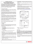
Installing Cellular Modules on the TC-DK10-T
and TC-DK20-T
The TC-DK10-T and TC-DK20-T have four mini PCIe sockets that allow you to install four cellular modules.
However, they come with different interfaces. Check the following table for details.
Model
TC-DK10-T
TC-DK20-T
Interface
Socket 1
Socket 2
Socket 3
Socket 4
Socket 1
Socket 2
Socket 3
Socket 4
PCIe V1.0
--
--
--
(One Lane)
USB 2.0
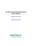
Before installing a cellular module, verify the locations of the mini PCIe sockets on the front side and match
them to the SIM sockets on the rear. If you install a cellular module in socket 1, you will need to install a SIM
card in SIM socket 1.
Front View
Rear View
Note that you must specify a different SMBus address for each TC-DK01-T/TC-DK20-T module. This is done by
adjusting the DIP switch. The diagram below shows the location of the DIP switch, and provides a table that
maps the DIP switch value to the SMBus address it is associated with.
Value
3-5
SMBus Address
0
0x27
1
0x26
2
0x25
3
0x24
4
0x23
5
0x22
6
0x21
7
0x20
TC-6000 Series Expansion Modules
Hardware Connection Description
ATTENTION
Slot
You must be sure to set each module’s SMBus address to a distinct value.
Value
Address
Do not set any cards with duplicate values, or you will create unpredictable 1
1
0x26
behavior (bugs) in your system.
2
2
0x25
3
3
0x24
4
4
0x23
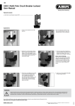
Installing a Cellular Module
A single cellular accessory package includes a cellular module, a cellular antenna cable (that ends in an F type
barrel connector on one and a crimped slider on the other), two black screws, a locking washer, and a nut.
Follow the steps below to install a cellular module.
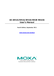
1. Insert the cellular module into the socket. Secure the module with 2 black screws.
2. Connect the antenna cable to the module. Make sure that the cable has been securely fastened.
3. Slide the F type connector of the antenna cable into the antenna hole on
the face of the module. Slide the locking washer over the barrel
connector, and then secure the connector to the face of the module
using the nut.
4. After you have installed the antenna’s barrel connector to the face of
the module, connect the cellular antenna.
3-6
TC-6000 Series Expansion Modules
Hardware Connection Description
5. Next, insert the SIM card for the cellular module. Pull up the SIM card slot and insert the SIM card. When
finished, replace the holder and slide the slot towards the catch to fasten the holder
6. You can use the same procedure to install another cellular module on another socket.
Installing the SSD/HDD into the TC-SATA
Module
Follow these steps to install the SSD/HDD into the TC-STAT storage module. The TC-STAT storage module has
a double-PCB design, with an upper PCB and a lower PCB. The upper PCB is the module’s main board.
1. Remove the storage tray from the computer.
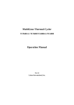
2. Remove the six screws that fasten the upper PCB to the storage tray. These are circled in red, on the figure
below. Note that it is not necessary to remove the remaining three screws.
3. Detach the SATA power and data interfaces from the main board by
carefully sliding the tray away from the main PCB.
4. Remove the four screws securing the lower PCB to the
module tray, and remove the lower PCB.
3-7
TC-6000 Series Expansion Modules
Hardware Connection Description
5. Slide the SSD/HDD into the lower PCB in such a way that
the module’s data and power interface securely connect
with the PCB’s power and data interface.
6. Carefully turn the tray over and fasten the drive to the
PCB using the holes indicated in the photo.
7. Fasten the lower PCB to the module’s tray (drive-side up,
as shown) using the four screw holes shown at right.
8. First, connect the upper PCB / main board’s power and
data cables to the lower PCB interface. Then complete
the installation by fastening the drive tray to the main
PCB using the six screws.
9. You may now insert the storage tray back into the TC-6110 and tighten the external thumbscrews.
Note that each removable drive module has a hot-swap button and four LED indicators. To hot swap storage
drives you will need to first install the Moxa hot swap software package, as described in the TC-6110
software manual. Once installed, to hot swap a drive you must use a sharp object to push the hot swap
button (labeled X1, on the front panel map) and wait until the L1 LED indicator goes dark, indicating the drive
has unmounted and is ready for extraction. The L3 and L4 LEDs are programmable, to be defined by users.
Refer to the software manual for more details about the Moxa hot swap software package and programming the
LEDs. The following table describes the functions associated with each LED and button.
3-8
TC-6000 Series Expansion Modules
LED Indicator/Button
L1
Hardware Connection Description
Function
On
HDD is accessing data
Off
No activity
Heater is on in specific environments. Refer to
Blinking
L2
Off
the following conditions:
•
Below 55°C when power is available.
•
Below 15°C when system is on.
Heater is off
L3
Defined by admin
L4
Defined by admin
X1
Hot-swap button, for unmounting drives
3-9
4
4.
Software Installation and Programming
Guide
In this chapter we discuss software installation and programming for the TC-6000 series expansion modules
TC-SP04-DB44-T, TC-CP02-DB-T, and TC-DK10-T/TC-DK20-T.
The following topics are covered in this chapter:
Linux System Peripherals Programming Guide
Prerequisite for Installing Peripheral Modules
TC-SP04-DB44-T: Serial Port
TC-CP02-DB-T: CAN Bus Interface
TC-DK10-T/TC-DK20-T: mini PCIe Interface
Windows System
TC-SP04-DB44-T: Driver Installation
TC-SP04-DB44-T: Configuring Serial Port Mode
TC-CP02-DB-T: Driver Installation
TC-CP02-DB-T CAN Module: Programming Guide
TC-DK10-T/TC-DK20-T: Enabling/Disabling USB Socket Power
TC-6000 Series Expansion Modules
Software Installation and Programming Guide
Linux System Peripherals Programming Guide
Prerequisite for Installing Peripheral Modules
Two methods can be used for installing required drivers and utilities. One method uses APT for an automated
online installation, while the other involves downloading the driver from the Moxa website and installing it by
hand.
Installation of Linux Modules Using APT
To guarantee you are getting safe software from the correct source, Moxa’s repository packages are encrypted
with a Gnu Privacy Guard (GPG) key. Before installing the modules, you should add the Moxa GPG key. You can
find the GPG key on the product CD or at the Moxa website. Upload the key to the TC-6000 and add it with the
following command.
Moxa:~# apt-key add MOXA-SYS-DEBIAN-KEY
To use APT to download and install software, you must first add the Moxa repository to the sources file, found
at /etc/apt/source.list.
1. First, back up your sources.list file:
Moxa:~# cp /etc/apt/sources.list /etc/apt/sources.listBAK
2. Add the Moxa repository by using the echo command
Moxa:~# echo ‘deb http://debian.moxa.com/debian wheezy main’ >> /etc/apt/source.list
3. Update the package list for retrieving the latest package list.
Moxa:~#
apt-get update
Get:1 http://debian.moxa.com wheezy Release.gpg [490 B]
Hit http://debian.moxa.com wheezy Release
Hit http://debian.moxa.com wheezy/main i386 Packages
Ign http://debian.moxa.com wheezy/main Translation-en_US
Ign http://debian.moxa.com wheezy/main Translation-en
Hit http://ftp.us.debian.org wheezy Release.gpg
Hit http://security.debian.org wheezy/updates Release.gpg
Hit http://ftp.us.debian.org wheezy-updates Release.gpg
Hit http://ftp.us.debian.org wheezy Release
Hit http://security.debian.org wheezy/updates Release
Hit http://ftp.us.debian.org wheezy-updates Release
Hit http://security.debian.org wheezy/updates/main Sources
Hit http://ftp.us.debian.org wheezy/main Sources
Hit http://security.debian.org wheezy/updates/main i386 Packages
Hit http://ftp.us.debian.org wheezy/main i386 Packages
Hit http://ftp.us.debian.org wheezy/main Translation-en
Hit http://security.debian.org wheezy/updates/main Translation-en
Hit http://ftp.us.debian.org wheezy-updates/main Sources
Hit http://ftp.us.debian.org wheezy-updates/main i386 Packages/DiffIndex
Hit http://ftp.us.debian.org wheezy-updates/main Translation-en/DiffIndex
Fetched 490 B in 2s (195 B/s)
Reading package lists... Done
4. Next, use apt-get search tc6000 to check if your package list has been updated.
Moxa:~# apt-cache search tc6000
tc6000-mpcie-power - utility for control the mini-PCIe power status.
tc6000-mxser - module of MOXA's serial devices
tc6000-qmi-modules - modules for QMI devices
tc6000-setinterface - a utility for get or set the mode for serial interfaces.
4-2
TC-6000 Series Expansion Modules
Software Installation and Programming Guide
tc6000-socketcan - modules for CAN device using socketCAN
The following table shows the packages required for each expansion modules:
Expansion Module
Driver Package Name
Utility Packages Name
TC-SP04-DB44-T
tc6000-mxser
tc6000-setinterface
TC-CP02-DB-T
tc6000-socketcan
TC-DK10-T/TC-DK20-T
tc6000-qmi-modules
libqmi-glib1, libqmi-utils ,
tc6000-mpcie-power
After setting up the repository, use apt-get or Aptitude to install the package.
Moxa:~# apt-get install package-name
To uninstall the package, use the following command.
Moxa:~# apt-get remove package-name
Installing Linux Modules from the Moxa Website
The following table shows the various drivers and utilities required for each expansion module. You may acquire
these kernel modules from the Moxa website, on the TC-6000 Expansion Modules product page, which should
be at http://www.moxa.com/support/sarch_result.aspx?prod_id=1990. Click into the Drivers link,
and download the correct kernel module according to the chart below:
Expansion Module
Kernel Module Package
Utility Package
TC-SP04-DB44-T
tc6000-mxser_1.15.21_i386.deb
tc6000-setinterface_1.0_i386.deb
TC-CP02-DB-T
tc6000-socketcan_1.0_i386.deb
TC-DK10-T/TC-DK20-T
tc6000-qmi-modules_1.0_i386.deb libqmi-glib1_1.8.0-1_i386.deb,
libqmi-utils_1.8.0-1_i386.deb,
tc6000-mpcie-power_1.0_i386.deb
libffi5_3.0.10-3_i386.deb
libglib2.0-0_2.33.12+really2.32.4-5_i386.deb
To install a package you have downloaded from the website, navigate to the directory it is stored in and type:
Moxa:~# dpkg -i package-file
To uninstall the package, use
Moxa:~# dpkg -r package-file
TC-SP04-DB44-T: Serial Port
The TC-SP04-DB44-T may be accessed over the Linux console as a terminal (tty) device node. The Moxa driver
creates a special device node that is identified as a ttyM* device. The TC-SP04-DB44-T device nodes are listed
from /dev/ttyM0 to /dev/ttyM15, depending on how many expansion modules inserted. The UART API
allows you to configure these device nodes for RS-232, RS-422, 4-wire RS-485, or 2-wire RS-485.
The serial port kernel module for the TC-SP04-DB44-T is mxser.ko, and has been pre-installed at
/lib/modules/3.2.0-4-686-pae/updates/drivers/tty/mxser.ko. Whenver the module is loaded
the serial ports will be automatically enabled whenever the system boots up.
ATTENTION
The maximum baudrate for the serial ports is 115,200; the stock serial ports on the TC-6000 series do not
support baudrates beyond this maximum. However, the serial port expansion module does support baudrates
up to 921,600. Standard baudrates are: 50, 75, 110, 134, 150, 200, 300, 600, 1200, 1800, 2400, 4800, 9600,
19200, 38400, 57600, 115200, 230400, 460800, and 921600. To configure the above code for a standard
baudrate connection, simply insert the number at the indicated line.
Non-standard baudrates are more fully explained below
4-3
TC-6000 Series Expansion Modules
Software Installation and Programming Guide
WARNING
If you use the stty command to get interface stats from a connection configured for a non-standard baudrate,
the system will return a rate of 0.
TC-SP04-DB44-T: Configuring the Baudrate
Example Script #1: Setting the Baudrate)
#define MOXA
0x400
#define MOXA_SET_SPECIAL_BAUD_RATE
(MOXA+100)
#define MOXA_GET_SPECIAL_BAUD_RATE
(MOXA+101)
#include
<termios.h>
struct termios term;
int
fd, speed;
fd = open(“/dev/ttyM8”, O_RDWR);
tcgetattr(fd, &term);
term.c_cflag &= ~(CBAUD | CBAUDEX);
term.c_cflag |= B4000000;
tcsetattr(fd, TCSANOW, &term);
speed = 115200;
ioctl(fd, MOXA_SET_SPECIAL_BAUD_RATE, &speed);
Example Script #2: Return the Baudrate
#define MOXA
0x400
#define MOXA_SET_SPECIAL_BAUD_RATE
(MOXA+100)
#define MOXA_GET_SPECIAL_BAUD_RATE
(MOXA+101)
#include
<termios.h>
struct termios term;
int
fd, speed;
fd = open(“/dev/ttyM8”, O_RDWR);
tcgetattr(fd, &term);
if ( (term.c_cflag & (CBAUD|CBAUDEX)) != B4000000 ) {
// On this line, you may insert a standard baud rate
} else {
ioctl(fd, MOXA_GET_SPECIAL_BAUD_RATE, &speed);
}
Non-Standard Baudrates and Baudrate Inaccuracy
Moxa’s drivers allow engineers to configure our serial devices for non-standard baudrates. Theoretically, these
devices may be set for any baudrate; however, in practice the only non-standard rates that will communicate
at the chosen baudrate are whole number factors of the base rate, 921,600 bps. For any non-standard rates
that are not a whole number factor of 921,600, there will be some inaccuracy in transmission speed relative to
the configured rate.
Standard baudrates are 50, 75, 110, 134, 150, 200, 300, 600, 1200, 1800, 2400, 4800, 9600, 19200, 38400,
57600, 115200, 230400, 460800, and 921600. Moxa’s drivers allow for any whole number factor of 921,600 to
be used without any performance loss (i.e., inaccuracy or deviation from the TBR) in the configured modulation
rate. To calculate the relative inaccuracy for non-standard baudrates that are not a whole number factor of
921,600, use the formula below:
4-4
TC-6000 Series Expansion Modules
Root formula: Inaccuracy =
Software Installation and Programming Guide
TBR – 921600/(Factor + ENUM/8)
(TBR) 100
The variables in this equation are described below:
TBR = The Target Baud Rate, i.e., any non-standard baudrate
Factor = 921,600/TBR (rounded down to the integer)
ENUM = 8 * (921600/Target baudrate - Factor) (Round up or down)
As an example, below we show you how to calculate the transmission inaccuracy at a target baudrate (TBR) of
500,000 bps:
Target (non-standard) Baud Rate = 500,000
Factor =
921,600
500,000
= 1.8, then round down to the nearest integer to get 1.
921,600
ENUM = 8 �500,000 − 1� = 6.7, round to the nearest integer to get 7.
Inaccuracy =
500,000 – 921600/(1 + 7/8)
�500,000� 100
= 1.696 = 1.7%
This result indicates that for a device configured at the non-standard rate of 500,000 bps, the actual modulation
rate will deviate around 2% from the configured baudrate.
TC-SP04-DB44-T: Configuring Serial Port Modes
Use the setinterface command to retrieve the parameters of the serial port configuration. The usage is
$:~# setinterface [device node] [interface option]. The device node is the tty device to be
configured. For the serial ports, Moxa uses a proprietary driver whose device nodes are identified with the
marker M. Serial ports 1 to 4 on card 1 are referred to as ttyM0 to ttyM3, and ttyM4 to ttyM7 refer to ports
1 to 4 on the second card and so on. The interface option is a number between 0 and 3 that will determine
what serial interface should be configured for the port in question. For example:
$:~# setinterface /dev/ttyM0 0
sets the first serial port on the first card for RS-232 communications. Refer to the examples below for details.
Moxa:~# setinterface
Usage: setinterface device-node [interface-no]
device-node - /dev/ttyM0 ~ /dev/ttyM15
interface-no
- following:
none - to view now setting
0 - set to RS232 interface
1 - set to RS485-2WIRES interface
2 - set to RS422 interface
3 - set to RS485-4WIRES interface
Moxa:~#
Checking Current Serial Settings
To check the current interface setting, type the following. The system should display a response as below.
Moxa: ~# setinterface /dev/ttyM0
Now setting is RS485-2WIRES interface.
In the example above, port 1 on card 1 is configured as a 2-wire RS-485 interface. After entering the lines of
code below, port 1 gets reset as an RS-422 interface.
Moxa: ~# setinterface /dev/ttyM0 2
Moxa: ~# setinterface /dev/ttyM0
4-5
TC-6000 Series Expansion Modules
Software Installation and Programming Guide
Now setting is RS422 interface.
ATTENTION
Serial interfaces will shift device node identifiers depending upon the location and number of cards
mounted in the platform. E.g. if there are originally two cards mounted in the machine, and card number 1 is
removed, then the second card’s number will change from /dev/ttyM4 to /dev/ttyM7 to /dev/ttyM0 and
/dev/ttyM3.
If a user wants to configure the machine for fixed serial interface device node identifiers, you can create a UDEV
rule in /etc/udev/rules.d/. For help with this, you may consult the UDEV manual files, another Linux
manual, or Moxa technical support for more details.
The system default for TC-SP04-DB44-T interfaces is RS-232. By editing the device manager’s rule scripts, it is
possible to set all serial ports to one of the serial protocols (RS-485 or RS-422) instead. The following steps
describe how to do so.
1. Edit Moxa’s custom rules file for the device manager, which can be found at
/etc/udev/rules.d/96-moxa.rules. Add the following command to 96-moxa.rules:
RUN+="/bin/setinterface /dev/ttyM%n 0”
# Set the device, TC-SP04-DB44-T, 0x1393:0x1042 default as 232 mode interface
DRIVERS=="mxser", ATTRS{vendor}=="0x1393", ATTRS{device}=="0x1042",
RUN+="/bin/setinterface /dev/ttyM%n 0"
"96-moxa.rules"
ATTENTION
The VendorID for the TC-SP04-DB44-T is 0x1393, and the DeviceID is 0x1042.
2. To change the default serial interface mode, edit the setinterface command you have just added to the
Moxa rules file (/etc/udev/rules.d/96-moxa.rules). This will cause the Linux kernel to automatically
set the TC-6000 series module to your preferred interface at every reboot.
•
•
•
•
For RS-232, use RUN+="/bin/setinterface /dev/ttyM%n 0"
For RS-485 2-wire, use RUN+="/bin/setinterface /dev/ttyM%n 1"
For RS-422, use RUN+="/bin/setinterface /dev/ttyM%n 2"
For RS-485 4-wire, use RUN+="/bin/setinterface /dev/ttyM%n 3"
3. When finished, you must un-mount the writable file system and reboot your computer
Moxa:~# umount /
Moxa:~# reboot
4. Once the computer restarts, confirm that the interfaces have been reset to your preferred interface settings.
Moxa:~# setinterface /dev/ttyM0
Now setting is RS485-2WIRES interface.
TC-CP02-DB-T: CAN Bus Interface
The TC-CP02-DB-T module provides TC-6000 series computers with a CAN bus interface. CAN is a broadcast
serial bus standard for connecting electronic control units (ECUs). Each node is able to send and receive
messages, but not simultaneously: a message (consisting primarily of an ID—usually chosen to identify the
message-type/sender—and up to eight message bytes) is transmitted serially onto the bus, one bit after
another. This signal-pattern codes the message (in NRZ) and is sensed by all nodes.
The Moxa TC-CP02-DB-T module provides the CAN bus interface for industrial CAN communication. TC-6000
series computer provide the SocketCAN interface for industrial CAN communication. The SocketCAN concept
4-6
TC-6000 Series Expansion Modules
Software Installation and Programming Guide
extends the Berkeley sockets API in Linux by introducing a new protocol family, PF_CAN, that coexists with
other protocol families like PF_INET for the Internet Protocol.
You can use the file control interface to read, write or control the CAN interface as a file for easy CAN
programming.
TC-CP02-DB-T: Driver Installation
The drivers for Moxa TC-SP04-DB44-T module include can.ko, can_raw.ko, can_bcm.ko, can_dev.ko,
sja1000.ko, and plx-pci.ko . These have all been pre-installed under:
/lib/modules/3.2.0-4-686-pae/updates/drivers/net/can
Some drivers will be loaded by the boot process when modules are inserted; others must be loaded manually,
using modprobe:
Moxa:~# modprobe can
Moxa:~# modprobe can_raw
Moxa:~# modprobe can_bcm
You may set modules to load automatically at boot by listing them in the /etc/modules file.
TC-CP02-DB-T: Configuring the Socket CAN Interface
After the modules have been loaded, the next step is to configure the CAN interface and start it as a standard
net interface. Here’s an example with bitrate 12500:
# ip link set can0 up type can bitrate 12500
# ip link set can1 up type can bitrate 12500
The SocketCAN information is stored under /proc/net/can; you can determine what version is being used by
using the cat command:
Moxa~:# cat /proc/net/can/version
and return usage/operating statistics thus:
Moxa~:# cat /proc/net/can/stats
TC-CP02-DB-T: Sample Script for the SocketCAN API
The following code is a working example of the SocketCAN API in use; this code sends a CAN packet using the
raw interface. It is based on the notes documented in the Linux Kernel
(https://www.kernel.org/doc/Documentation/networking/can.txt).
#include
#include
#include
#include
<stdio.h>
<stdlib.h>
<unistd.h>
<string.h>
#include
#include
#include
#include
<net/if.h>
<sys/types.h>
<sys/socket.h>
<sys/ioctl.h>
#include <linux/can.h>
#include <linux/can/raw.h>
int
main(void)
{
int s;
4-7
TC-6000 Series Expansion Modules
Software Installation and Programming Guide
int nbytes;
struct sockaddr_can addr;
struct can_frame frame;
struct ifreq ifr;
char *ifname = "can0";
if((s = socket(PF_CAN, SOCK_RAW, CAN_RAW)) < 0) {
perror("Error while opening socket");
return -1;
}
strcpy(ifr.ifr_name, ifname);
ioctl(s, SIOCGIFINDEX, &ifr);
addr.can_family = AF_CAN;
addr.can_ifindex = ifr.ifr_ifindex;
printf("%s at index %d\n", ifname, ifr.ifr_ifindex);
if(bind(s, (struct sockaddr *)&addr, sizeof(addr)) < 0) {
perror("Error in socket bind");
return -2;
}
frame.can_id
frame.can_dlc
frame.data[0]
frame.data[1]
=
=
=
=
0x123;
2;
0x11;
0x22;
nbytes = write(s, &frame, sizeof(struct can_frame));
printf("Wrote %d bytes\n", nbytes);
return 0;
}
The following is sample code for reading data.
#include
#include
#include
#include
<stdio.h>
<stdlib.h>
<unistd.h>
<string.h>
#include
#include
#include
#include
<net/if.h>
<sys/types.h>
<sys/socket.h>
<sys/ioctl.h>
#include <linux/can.h>
#include <linux/can/raw.h>
int
main(void)
{
int i;
int s;
int nbytes;
struct sockaddr_can addr;
struct can_frame frame;
4-8
TC-6000 Series Expansion Modules
Software Installation and Programming Guide
struct ifreq ifr;
char *ifname = "can0";
if((s = socket(PF_CAN, SOCK_RAW, CAN_RAW)) < 0) {
perror("Error while opening socket");
return -1;
}
strcpy(ifr.ifr_name, ifname);
ioctl(s, SIOCGIFINDEX, &ifr);
addr.can_family = AF_CAN;
addr.can_ifindex = ifr.ifr_ifindex;
printf("%s at index %d\n", ifname, ifr.ifr_ifindex);
if(bind(s, (struct sockaddr *)&addr, sizeof(addr)) < 0) {
perror("Error in socket bind");
return -2;
}
nbytes = read(s, &frame, sizeof(struct can_frame));
if (nbytes < 0) {
perror("Error in can raw socket read");
return 1;
}
if (nbytes < sizeof(struct can_frame)) {
fprintf(stderr, "read: incomplete CAN frame\n");
return 1;
}
printf(" %5s %03x [%d] ", ifname, frame.can_id, frame.can_dlc);
for (i = 0; i < frame.can_dlc; i++)
printf(" %02x", frame.data[i]);
printf("\n");
return 0;
}
4-9
TC-6000 Series Expansion Modules
Software Installation and Programming Guide
TC-DK10-T/TC-DK20-T: mini PCIe Interface
Moxa's TC-DK10-T and TC-DK20-T support 4 PCIe mini card sockets. However, they come with different
interfaces. Check the following table for details:
Model
Interface
PCIe V1.0
(One Lane)
USB 2.0
NOTE
TC-DK10-T
Socket 1 Socket 2
Socket 3
TC-DK20-T
Socket 4
Socket 1
Socket 2
Socket 3
Socket 4
--
--
--
You can use at most two TC-DK10-T/TC-DK20-T modules on a TC-6000 train computer, and the maximum
number of mini PCIe sockets that can be used is eight.
TC-DK10-T/TC-DK20-T: Configuring Power Controls
The TC-DK10-T/TC-DK20-T module comes with the capability of automating a device’s power state. Note,
however, that this function is provided primarily for powering on and off a PCIe module that uses a USB
interface. It is NOT advisable to use this function with PCIe devices, since the devices could be damaged. It is
also not advisable to use the power control feature with USB DOM devices, because these devices involve the
mounting and unmounting of file systems, and while the Linux system will be able to automatically mount the
USB DOM file systems as they come online, without careful scripting it will not be able to automatically unmount
the file systems once the device goes offline.
WARNING
Using the TC-DK10-T/TC-DK20-T’s onboard power controls for controlling PCIe or USB-DOM devices is
discouraged. Using the onboard power controls for controlling PCIe and USB-DOM devices may damage the
devices (PCIe) or corrupt data (USB-DOM). Any use of the TC-DK10-T/TC-DK20-T’s automated,
onboard power controls with PCIe and USB-DOM devices is undertaken at the user’s own risk.
Note that there is a further limitation: If you install a mini PCIe module that uses non-standard pin
definitions—such as Sierra Wireless module MC8090, MC9090, MC7304, MC7354—do not use the
power control function on the TC-DK10-T/TC-DK-20-T module. If you enable the power control function
for such a module, all access for SMBus will be locked until the system is rebooted. Read the specifications of
the mini PCIe modules you use carefully.
The command for manipulating the PCIe card’s power feature is mpcie-power. The precise syntax is as follows,
with chip address indicating the card to be configured, and slot_number indicating the number of the card
slot located on the TC-DK10-T/TC-DK20-T board itself. If the on/off flag is not specified, the command will
return the current power status:
# mpcie-power <address> <slot_number> [on/off flag]
The off flag is 0, and the on flag is 1.
Fox example, if you want to power off USB connectivity on slot 1 with some card, issue the following command:
# mpcie-power 0x27 1 0
Note that you can specify a different chip address for each TC-DK10-T/TC-DK20-T module by adjusting the DIP
switch. The location of the DIP switch is shown in the following figure. Refer to the mapping table to determine
which Chip Address corresponds to which DIP Switch Value:
4-10
TC-6000 Series Expansion Modules
Software Installation and Programming Guide
DIP Switch Value
Chip Address
0
0x27
1
0x26
2
0x25
3
0x24
4
0x23
5
0x22
6
0x21
7
0x20
ATTENTION
The mpcie-power command should not be used with the power on-off feature with a USB DOM module. This
is because when a USB DOM module is powered on, the Linux system will automatically mount its partitions,
but when it is powered off the system cannot automatically unmount its partitions.
Any use of the TC-DK10-T/TC-DK20-T’s automated, onboard power controls with PCIe interfaces
and USB-DOM devices is undertaken at the user’s own risk.
4-11
TC-6000 Series Expansion Modules
Software Installation and Programming Guide
Windows System
The following table shows the packages required for each expansion modules:
Module
Driver Package
TC-SP04-DB44-T
TC-SP04-DB44_mxser_1.18.2_Win7_x86.zip
TC-CP02-DB-T
TC-CP02_mxcan_1.0_Win7_x86.zip
TC-DK10-T/
Utility Package
TC-CP02_sample_1.0_Win7_x86.zip
TC-DK00_sample_1.0_Win7_x86.zip
TC-DK20-T
The drivers used in this section can be obtained from the official website:
http://www.moxa.com/product/TC-6000-Series-Expansion-Modules.htm
TC-SP04-DB44-T: Driver Installation
Before using the TC-SP04-DB44-T expansion module, you need to update the driver. Install the driver before
mounting the expansion module in the slot.
1. Right-click the PCI Serial Port device and select Update Driver Software.
2. Click Browse my computer for driver software to install using default settings.
4-12
TC-6000 Series Expansion Modules
Software Installation and Programming Guide
3. Click Next to start the installation.
4. Click Close to complete the installation.
5. The driver will be installed automatically. The module should be listed in the Device Manager window. At
this point you can start using the module.
TC-SP04-DB44-T: Configuring Serial Port Mode
Take the following steps to configure the properties of each COM port:
1. Go to Control Panel System and Security Device Manager Ports (COM & LPT) and select the
COM port, such as Moxa Communication Port 1 (COM7).
4-13
TC-6000 Series Expansion Modules
Software Installation and Programming Guide
2. Right-click the COM port and then click Properties.
3. Click the Port Settings tab and then select the interface you would like to use.
4. Click OK to apply the settings.
4-14
TC-6000 Series Expansion Modules
Software Installation and Programming Guide
In some situations, you may want to change the port name to match the name used by your program. Take the
following steps to change port names:
1. Go to Control Panel System and Security Device Manager Multi-port serial adapters and
select the adapter.
2. Right-click the adapter and select Properties.
3. Click the Port Configuration tab, select the port, and then click Port Setting.
4. To change the port name separately, uncheck Auto Enumerating COM Number.
4-15
TC-6000 Series Expansion Modules
Software Installation and Programming Guide
5. Select the new port name and then click OK.
6. Make sure the port names are correct, and then click OK to activate the settings.
7. Refer to Ports (COM & LPT) to verify that the port names have been changed.
4-16
TC-6000 Series Expansion Modules
Software Installation and Programming Guide
TC-CP02-DB-T: Driver Installation
Before using the TC-CP02-DB-T expansion module, you need to update the driver. Install the driver before
inserting the expansion module in the slot. Take the following steps to install the CAN BUS driver:
1. Double-click mxcan_setup.msi to open the setup wizard that will install the module. Click Next.
2. Click Next to accept the installer defaults, and then click through the next dialog to install the driver.
3. Click Next to continue, or click Browse to select the folder to install the driver.
4. Click Next to continue.
4-17
TC-6000 Series Expansion Modules
Software Installation and Programming Guide
5. Select Install this driver software anyway twice to continue.
6. Click Finish.
7. After the driver is installed, click Close to complete the driver setup.
8. Click Yes to shut down the computer and install the TC-CP02 driver and then boot up again.
4-18
TC-6000 Series Expansion Modules
Software Installation and Programming Guide
9. Next, open the Windows Device Manager, right click on the computer located at the top of the tree, and
select Scan for hardware change to finish the installation.
TC-CP02-DB-T CAN Module: Programming Guide
Note that the driver and example code can be obtained from the official website:
http://www.moxa.com/product/TC-6000-Series-Expansion-Modules.htm
Refer to the following table for an introduction to the sample code for the TC-CP02-DB-T CAN module.
Sample Code
Description
mxcan_get_filter
Gets the filter values
mxcan_get_registers
Gets the register values
mxcan_get_status
Gets the CAN bus status
mxcan_ioctl_gettiming
Gets the bus timing of an open port.
mxcan_ioctl_settiming
Sets the bus timing of an open port.
mxcan_read
Reads data into a buffer from an open port (the size
should be a multiple of the CANMSG size)
mxcan_set_filter
Sets the filter values
mxcan_write
Writes data into a buffer from an open port (the size
should be a multiple of the CANMSG size)
Moxa CAN Bus Library
int mxcan_close (int fd)
Description
Close an open port.
Input
<fd> the open port
Return Value
None
4-19
TC-6000 Series Expansion Modules
Software Installation and Programming Guide
unsigned int mxcan_get_bus_timing (int fd)
Description
Gets the bus timing of an open port.
Input
<fd> the open port
Return Value
0 on failure, otherwise the bus speed in KHz
int mxcan_get_parameters (int fd, CANPRM * param)
Description
Gets the parameter of an open port.
Input
<fd> the open port
Output
< param> pointer to the CANPRM structure
Return Value
0 on failure, otherwise returns a negative value
int mxcan_get_registers (int fd, unsigned char * buffer, int num)
Description
Gets the register values of an open port.
Input
<fd> the open port
Output
< buffer > pointer to a buffer for these values
<num> number of register values; for a module with sja1000 chipset, the value must be 32
Return Value
0 on success; other numbers indicate failure
int mxcan_get_stat (int fd, CANBST * stat)
Description
Gets the statistics of an open port.
Input
<fd> the open port
Output
< stat > pointer to a container of the statistics
Return Value
0 on success; other numbers indicate failure
int mxcan_inqueue (int fd)
Description
Gets the number of received bytes that are queued in the driver of an open port.
Input
<fd> the open port
Return Value
0 on failure; otherwise the number of bytes
int mxcan_open (int port)
Description
Open a can port given the port number.
Input
<port> port number starting from 1; in Linux, open port 1 will open /dev/can0
Return Value
-1 on failure; otherwise returns fd
int mxcan_outqueue (int fd)
Description
Gets the number of bytes waiting to be transmitted to a can port.
Input
<fd> the open port
Return Value
-1 on failure; otherwise the number of bytes
int mxcan_purge_buffer (int fd, unsigned int purge)
Description
Purges the buffers of an open port.
Input
<fd> the open port
Output
< purge> 1: received data buffer; 2: transmit data buffer; otherwise: both
Return Value
0 on success; otherwise failure
int mxcan_read (int fd, char * buffer, int size)
Description
Reads data into a buffer from an open port (the size should be a multiple of the CANMSG size)
Input
<fd> the open port
Output
<buffer> pointer to the buffer
Return Value
0 on failure (data not available); otherwise the number of bytes read
4-20
TC-6000 Series Expansion Modules
Software Installation and Programming Guide
int mxcan_set_bus_timing (int fd, unsigned int speed)
Description
Sets the bus timing of an open port.
Input
<fd> the open port
Output
<speed> bus timing in Hz
Return Value
0 on success; otherwise returns a negative number
int mxcan_set_parameters (int fd, CANPRM * param)
Description
Sets the parameters of an open port.
Input
<fd> the open port
Output
<speed> bus timing in Hz
Return Value
0 on success; otherwise returns a negative number
<param> pointer to the CANPRM structure
int mxcan_write (int fd, char * buffer, int size)
Description
Writes data to the open port
Input
<fd> the open port
<buffer> pointer to the data
<size> size of the data (should be a multiple of the CANMSG size)
Return Value
0 on failure; otherwise the number of bytes written
TC-DK10-T/TC-DK20-T: Enabling/Disabling USB Socket
Power
Take the following steps to get the current USB power status.
1. Execute mx-tcdk-pwr-control.exe under \\TC-DK00-Windows\SampleCode\Release in the product
DVD.
2. Enter the slave address according to the switch jumper on the TC-DK10-T/TC-DK20-T modules.
3. Select (1) Get USB Slot Power to get current USB power status.
4-21
TC-6000 Series Expansion Modules
Software Installation and Programming Guide
4. Select the slot number. (For example, 1 for socket 1)
5. You will get the USB power status of socket 1.
Take the following steps to disable/enable the USB power.
1. Execute mx-tcdk-pwr-control.exe.
2. Enter the slave address according to the switch jumper on TC-DK10-T/TC-DK20-T modules.
3. Select (2) Set USB Slot Power to get the current USB power status.
4. Select the slot number. (For example, 1 for socket 1).
4-22
TC-6000 Series Expansion Modules
Software Installation and Programming Guide
5. Enter the option to disable/enable the USB power. (For example, entering 0 disables USB power)
6. Check if the USB power has been set successfully.
7. Check the Windows Device Manager to see if the device is disabled.
ATTENTION
Using the TC-DK10-T/TC-DK20-T’s onboard power controls (mx-tcdk-pwr-control.exe) for control of PCIe or
USB-DOM devices is discouraged. Using the onboard power controls for control of PCIe and USB-DOM devices
may damage the devices (PCIe) or corrupt data (USB-DOM). Any use of the TC-DK10-T/TC-DK20-T’s
automated, onboard power controls with PCIe and USB-DOM devices is undertaken at the user’s
own risk.
4-23