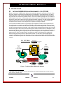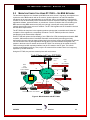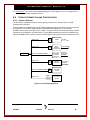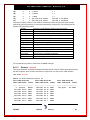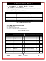
1
DT-7000 IP-CommKit™ Host Network Interface User's Manual Release.Version 1.0 Issue 2 379 Campus Drive, Suite 100 Somerset, NJ 08873 fax: 732 667-1091 phone: 732 667-1080 email: [email protected] http://www.datatekcorp.com DT-7000 User's Manual – Release 1.0 TABLE OF CONTENTS TABLE of CONTENTS.............................................................................................. 2 TABLE of FIGURES and TABLES ........................................................................... 6 Important Safety Instructions................................................................. 7 1 Introduction ........................................................................................................ 9 2 Overview ........................................................................................................... 11 3 2.1 Integrated BNS Network Environment – No DT-7000....................................................... 11 2.2 Migration Completion Using DT-7000’s – No BNS Network ............................................ 12 2.3 DT-7000 Logical Overview................................................................................................... 14 2.4 DT-7000 Features ................................................................................................................. 15 Physical Description........................................................................................ 16 3.1 Power Interfaces .................................................................................................................. 16 3.1.1 48V DC Power - In ......................................................................................................... 16 3.1.2 24V DC Power - In ......................................................................................................... 16 3.1.3 AC Power - In................................................................................................................. 16 3.1.4 Power Over Ethernet (POE) ......................................................................................... 16 3.1.5 DC Power - Out.............................................................................................................. 16 4 3.2 Alarm ..................................................................................................................................... 16 3.3 Serial Console (Con)............................................................................................................ 17 3.4 10/100 Base-T LAN............................................................................................................... 17 3.5 LEDs ...................................................................................................................................... 17 Equipment Installation .................................................................................... 18 4.1 Unpacking and Inspection .................................................................................................. 18 4.2 Required Equipment ............................................................................................................ 18 4.3 Mounting and Power Wiring................................................................................................ 18 4.3.1 Installation for AC Operation....................................................................................... 18 4.3.2 Installation for -48V DC Operation ............................................................................. 19 4.3.3 Installation for Power Over Ethernet (POE) Operation ............................................. 19 4.4 Console Connection and Configuration ............................................................................ 20 4.4.1 Console Cabling............................................................................................................ 20 4.4.2 Console Configuration Notes ...................................................................................... 21 4.5 5 Data Connections - LAN Port.............................................................................................. 21 Quick-Start Configuration Guide .................................................................... 22 5.1 Platform Configuration ........................................................................................................ 22 5.2 Configure the Local IP-CommKit Host............................................................................... 23 5.3 Configure Peers ................................................................................................................... 23 03/30/06 Datatek Applications Inc. 2 DT-7000 User's Manual – Release 1.0 5.4 Configure Vports.................................................................................................................. 24 5.4.1 Example - Type=rcv ...................................................................................................... 24 5.4.2 Example – Type=orig .................................................................................................... 24 6 DT-7000 Command Reference ........................................................................ 25 6.1 Input Conventions................................................................................................................ 25 6.2 Command Overview............................................................................................................. 25 6.3 System Platform Configuration – Non IP Network Commands....................................... 27 6.3.1 Help ................................................................................................................................ 27 6.3.2 Login .............................................................................................................................. 27 6.3.3 Logout and Exit............................................................................................................. 27 6.3.4 Label............................................................................................................................... 27 6.3.5 Banner............................................................................................................................ 28 6.3.6 Date and Timezone ....................................................................................................... 28 6.3.7 Change Password - chgpass....................................................................................... 29 6.3.8 Reset Password - rstpass ............................................................................................ 29 6.3.9 Console Timeout – timeout.......................................................................................... 30 6.4 System Platform Configuration – IP Network Related Commands ................................ 30 6.4.1 Closed User Groups – cug........................................................................................... 30 6.4.2 Console Administration - console .............................................................................. 30 6.4.3 IP Address(es) – IPaddr, Submask, IPother, IPpublic............................................... 31 6.4.4 Gateway ......................................................................................................................... 31 6.4.5 Hostname....................................................................................................................... 31 6.4.6 Host Names - hosts ...................................................................................................... 32 6.4.7 Domain Name Server - dns .......................................................................................... 32 6.5 Software Administration Commands................................................................................. 33 6.5.1 Install.............................................................................................................................. 33 6.5.2 Software Registration – register ................................................................................. 33 6.5.3 Backup and Retrieve Configuration Data – back or backup, retr or retrieve ......... 34 6.5.4 Version – ver or version ............................................................................................... 34 6.6 Reinitializing The DT-7000 - reboot .................................................................................... 34 6.7 Entity Definition Commands ............................................................................................... 35 6.7.1 Local Host Entity - host................................................................................................ 35 6.7.2 Remote DT-7000’s and IP-CommKit Hosts – peers................................................... 36 6.7.3 Other Remote IP Endpoints – vport ............................................................................ 36 6.7.3.1 Parameters for Type=orig Ports........................................................................... 37 6.7.3.2 Parameters for Type=rcv Ports ............................................................................ 37 6.7.3.3 Parameters Used by Both Types (Orig and Rcv) ............................................... 38 6.7.3.4 Examples using the incr parameter together with the cnt Parameter. ............ 38 6.7.4 Miscellaneous Entities – snmp.................................................................................... 40 6.8 Run-Time Commands .......................................................................................................... 40 6.8.1 Display Connections – dconn or dc............................................................................ 40 6.8.1.1 DT-7000 Connection Types .................................................................................. 40 6.8.1.2 Example – dc net ................................................................................................... 41 6.8.1.3 Example – dc host ................................................................................................. 42 6.8.1.4 Example – dc peer all ............................................................................................ 43 6.8.1.5 Example – dc vport................................................................................................ 43 6.8.1.6 Example – dc tcp ................................................................................................... 44 6.8.1.7 Example – dc pid ................................................................................................... 44 03/30/06 Datatek Applications Inc. 3 DT-7000 User's Manual – Release 1.0 6.8.2 Display Measurements – dm or dmeas ...................................................................... 45 6.8.2.1 Protocol Measurements........................................................................................ 45 6.8.2.2 TCP (con) Measurements – dm con..................................................................... 46 6.8.2.3 UTM Measurements – dm utm.............................................................................. 46 6.8.2.4 Clearing Measurements ........................................................................................ 48 6.8.3 Ping ................................................................................................................................ 48 6.8.4 Remove – rm, rem, or remove ..................................................................................... 48 6.8.5 Restore – rs, res, or restore......................................................................................... 48 6.8.6 Restart............................................................................................................................ 49 6.8.7 Snoop ............................................................................................................................. 49 6.8.8 Trace Route – tracert or trte ........................................................................................ 49 6.8.9 Verify - vfy..................................................................................................................... 50 6.8.9.1 Verify Module – vfy mod or vfymod..................................................................... 50 6.8.9.2 Verify DNS – vfy dns or dns vfy ........................................................................... 51 6.8.9.3 Verify SNMP – vfy snmp or snmp vfy .................................................................. 51 6.8.9.4 Verify Hosts – vfy hosts or hosts vfy .................................................................. 51 6.8.9.5 Verify Console – vfy console or console vfy ...................................................... 51 6.8.9.6 Verify Banner – vfy banner ................................................................................... 52 6.8.9.7 Verify Host – vfy host ............................................................................................ 52 6.8.9.8 Verify Vports – vfy vport <vport#>...................................................................... 52 6.8.9.9 Verify Peers – vfy peer <peer#> ........................................................................... 53 6.8.9.10 Verify Closed User Groups – vfy cug <cug#> .................................................... 54 6.8.9.11 Verify Standby – vfy stby or stby vfy................................................................... 54 6.8.10 Diag Command Family - diag ...................................................................................... 55 6.8.10.1 Address – diag address ........................................................................................ 55 6.8.10.2 Dev – diag dev........................................................................................................ 55 6.8.10.3 Ping – diag ping ..................................................................................................... 56 6.8.10.4 Tracert – diag tracert or diag trte ......................................................................... 56 6.8.10.5 URP – diag urp ....................................................................................................... 56 6.9 High Availability Option....................................................................................................... 57 6.9.1 Module Configuration for High Availability – ippublic, ipother................................ 57 6.9.2 Software Installation and Operational Configuration ............................................... 58 6.9.2.1 System Software Installation - stbyupd .............................................................. 58 6.9.2.2 Operational Configuration – stbyupd cfg ........................................................... 58 6.9.3 Automatic Standby Configuration Update – stby cfg ............................................... 58 6.9.4 Standby Logs – stby dlog, stby reset ......................................................................... 59 6.9.5 Switchover..................................................................................................................... 59 6.9.6 Commands Not Available in Standby Mode .............................................................. 60 7 8 9 Call Processing Overview ............................................................................... 61 7.1 Inbound Calls Via Vports..................................................................................................... 61 7.2 Outbound Calls .................................................................................................................... 61 7.3 Inbound Calls from Peers.................................................................................................... 62 Appendix A: Console Cable - Special Wiring Diagrams............................... 63 8.1 Console Cable Special Wiring ............................................................................................ 63 8.2 The DB9 Console Adapter................................................................................................... 64 Appendix B: Alarms......................................................................................... 65 03/30/06 Datatek Applications Inc. 4 DT-7000 User's Manual – Release 1.0 10 Appendix C: SNMP MIB Variable Database and Traps .............................. 67 10.1 SNMP MIB Variable Database ......................................................................................... 67 10.2 Supported Traps............................................................................................................... 69 11 Appendix D: TCP/UDP Port Numbers ......................................................... 70 12 Appendix E: The Display Measurements (dm|dmeas) Report .................. 71 12.1 IP ........................................................................................................................................ 71 12.1.1 Sample Report – dm ip ................................................................................................. 71 12.1.2 Measurement Descriptions - dm ip ............................................................................. 72 12.2 TCP..................................................................................................................................... 73 12.2.1 Sample Report – dm tcp............................................................................................... 73 12.2.2 Measurement Descriptions – dm tcp .......................................................................... 74 12.3 UDP .................................................................................................................................... 75 12.3.1 Sample Report – dm udp ............................................................................................. 75 12.3.2 Measurement Descriptions – dm udp......................................................................... 75 12.4 ICMP................................................................................................................................... 76 12.4.1 Sample Report – dm icmp............................................................................................ 76 12.4.2 Measurement Descriptions – dm icmp ....................................................................... 76 12.5 ETH..................................................................................................................................... 77 12.5.1 Sample Report – dm eth............................................................................................... 77 13 Appendix F: DT-7000 Specifications ........................................................... 78 13.1 Con (Console) ................................................................................................................... 78 13.2 10/100 Base-T LAN ........................................................................................................... 78 13.3 Physical Dimensions........................................................................................................ 78 13.4 Environmental Operating Range .................................................................................... 78 13.5 Power Requirements........................................................................................................ 78 13.6 Regulatory Information .................................................................................................... 79 14 Hardware Warranty ....................................................................................... 80 15 End-User License Agreement for Software ................................................ 80 15.1 Software License .............................................................................................................. 80 15.2 Intellectual Property Rights............................................................................................. 80 15.3 Software Support.............................................................................................................. 81 15.4 Export Restrictions .......................................................................................................... 81 15.5 Limited Warranty .............................................................................................................. 81 15.6 No Other Warranties......................................................................................................... 81 15.7 Special Provisions............................................................................................................ 81 16 Limitation of Liability.................................................................................... 82 03/30/06 Datatek Applications Inc. 5 DT-7000 User's Manual – Release 1.0 TABLE OF FIGURES AND TABLES FIGURE 1: TRADITIONAL MIXED BNS AND IP NETWORK ............................................... 11 FIGURE 2: MIXED NETWORK WITH DT-7000’S.............................................................. 12 FIGURE 3: LOGICAL DT-7000 INTERFACES AND FUNCTIONS ........................................ 14 FIGURE 4: DT-7000 FRONT VIEW ............................................................................... 16 FIGURE 5: DT-7000 FRONT VIEW ............................................................................... 18 FIGURE 6: CONSOLE WIRING OPTIONS ........................................................................ 20 FIGURE 7: CONSOLE RECEPTACLE PIN ASSIGMENT ..................................................... 63 FIGURE 8: SPECIAL WIRING FOR CONSOLE MODULAR CABLE ....................................... 63 FIGURE 9: 9-PIN CONSOLE ADAPTER WIRING DIAGRAM ............................................... 64 TABLE 1: BACKGROUND DOCUMENTATION .................................................................. 10 TABLE 2: DT-7000 LEDS .......................................................................................... 17 TABLE 3: CONSOLE CABLE ORDER INFORMATION ........................................................ 21 TABLE 4: CATEGORY 5 CABLE ORDERING INFORMATION .............................................. 21 TABLE 5: COMMAND REFERENCE TABLE ..................................................................... 26 TABLE 6: TCP CONNECTION STATES .......................................................................... 42 TABLE 7: CALL STATES ............................................................................................. 43 TABLE 8: DM UTM REPORT COLUMN HEADING EXPLANATION ..................................... 47 TABLE 9: DISALLOWED COMMANDS ON STANDBY PROCESSOR ..................................... 60 TABLE 10: ALARMS SEVERITY AND TEXT (SIMPLEX SYSTEMS)...................................... 65 TABLE 11: ADDITIONAL ALARMS - SEVERITY AND TEXT ( DUPLEX SYSTEMS)................. 66 TABLE 12: SNMP COMMANDS AND ACTION ................................................................ 67 TABLE 13: SNMP MIB-II VARIABLES ......................................................................... 67 TABLE 14: SUPPORTED SNMP TRAPS ........................................................................ 69 TABLE 15: TCP/UDP PORT NUMBERS USED .............................................................. 70 TABLE 16: ENVIRONMENTAL OPERATING RANGES ....................................................... 78 TABLE 17: POWER REQUIREMENTS ............................................................................ 78 TABLE 18: REGULATORY INFORMATION ....................................................................... 79 03/30/06 Datatek Applications Inc. 6 DT-7000 User's Manual – Release 1.0 Important Safety Instructions ! The exclamation point within an equilateral triangle is intended to alert the user to the presence of important operating and maintenance (servicing) instructions in the literature accompanying the product. When installing, operating, or maintaining this equipment, basic safety precautions should always be followed to reduce the risk of fire, electric shock, and injury to persons, including the following: ! Read and understand all instructions. ! Follow all warnings and instructions marked on this product. ! For information on proper mounting instructions, consult the User’s Manual provided with this product. ! The telecommunications interface should not leave the building premises unless connected to telecommunication devices providing primary and secondary protection. ! This product should only be operated from the type of power source indicated in the User’s Manual. ! This unit is powered from either –48 V DC, -24 V DC or AC voltage sources. See later sections in this manual before connecting to the power source. ! The –48 V DC input terminals are only provided for installations in Restricted Access Areas locations. ! Do not use this product near water, for example, in a wet basement. ! Never touch uninsulated wiring or terminals carrying direct current or leave this wiring exposed. Protect and tape wiring and terminals to avoid risk of fire, electric shock, and injury to service personnel. ! To reduce the risk of electrical shock, do not disassemble this product. Trained personnel should perform Service only. Opening or removing covers and/or circuit boards may expose you to dangerous voltages or other risks. Incorrect re-assembly can cause electric shock when the unit is subsequently used. ! For a unit intended to be powered from –48 V DC voltage sources, read and understand the following: • This equipment must be provided with a readily accessible disconnect device as part of the building installation. • Ensure that there is no exposed wire when the input power cables are connected to the unit. • Installation must include an independent frame ground drop to building ground. Refer to User’s Manual. This symbol is marked on the DT-7000, adjacent to the ground (earth) area for the connection of the ground (earth) conductor. 03/30/06 Datatek Applications Inc. 7 DT-7000 User's Manual – Release 1.0 • ! This Equipment is to be Installed Only in Restricted Access Areas on Business and Customer Premises Applications in Accordance with Articles 110-16, 110-17, and 110-18 of the National Electrical Code, ANSI/NFPA No. 70. Other Installations Exempt from the Enforcement of the National Electrical Code May Be Engineered According to the Accepted Practices of the Local Telecommunications Utility. For a unit to be used with an AC Wall Plug-In Unit, read and understand the following: • The DT-7000 was tested with the PHIHONG, Model PSA-30U-240 wall plug-in unit, which is an approved AC to –24 VC DC Wall Plug-In unit. • Unplug this product from the wall outlet before cleaning. Do not use liquid cleaners or aerosol cleaners. Use a damp cloth for cleaning. • Do not staple or otherwise attach the power supply cord to the building surfaces. • Do not overload wall outlets and extension cords as this can result in the risk of fire or electric shock. • The socket outlet shall be installed near the equipment and shall be readily accessible. • The Wall Plug-In unit may be equipped with a three-wire grounding type plug, a plug having a third (grounding) pin. This plug is intended to fit only into a grounding type power outlet. Do not defeat the safety purpose of the grounding type plug. • Do not allow anything to rest on the power cord. Do not locate this product where persons walking on it may abuse the cord. • Unplug this product from the wall outlet and refer servicing to qualified service personnel under the following conditions: a) When the power supply cord or plug is damaged or frayed. b) If liquid has been spilled into the product. c) If the product has been exposed to rain or water. d) If the product does not operate normally by following the operating instructions. Adjust only those controls that are covered by the operating instructions because improper adjustment of other controls may result in damage and will often require extensive work by qualified technician to restore the product to normal operation. e) If the product has been dropped or the cabinet has been damaged. f) If the product exhibits a distinct change in performance. SAVE THESE INSTRUCTIONS 03/30/06 Datatek Applications Inc. 8 DT-7000 User's Manual – Release 1.0 1 INTRODUCTION Datatek Applications, Inc. provides several products specifically engineered to facilitate the migration 1 from networks based on the Lucent Technologies BNS-2000/BNS-2000 VCS family (a.k.a. Datakit II VCS) to Internet Protocol (IP) networks. The DT-7000 is the final product that is needed to complete the migration. 2 Datatek previously provided high-level migration plans by which a customer's BNS network may be reduced to one or more nodes. These nodes that are remaining would now only need to handle the COMMKIT hosts that serve the Operations Systems (OS) applications. As a further step in the migration, if the CPM-HS modules were replaced in the remaining nodes with Universal Trunk Modules (UTM’s) and the CommKit software in the hosts with IP-CommKit software, the connections between the nodes and hosts could now traverse an IP network. An additional benefit is that the remnant BNS nodes no longer needed to be co-located with the OS hosts. Furthermore, in the nodes, the Universal Mediation Interface modules (UMI’s) could be used. These modules allow connectivity over IP to non-BNS endpoints, thereby eliminating the need for the BNS network to have any endpoint connectivity. The net result of the migration strategies presented prior to the introduction of the DT-7000 was a remnant set of BNS nodes whose sole purpose was to interface to IP-COMMKIT hosts and to the IP network via UMI modules for endpoint connectivity. While all other BNS modules may have been retired from this scenario by employing the proper Datatek migration products, the BNS/Datakit node’s cabinet, shelves, controller modules, UTM, and UMI modules must be continued in service. With the introduction of a new product, the DT-7000, the final step in the migration to a totally IP network can be completed. The DT-7000 will allow the retirement of the remnant set of nodes and hence, the last vestiges of the Lucent Technologies BNS/Datakit network. To aid the reader’s understanding, the documents shown in the Table 1 on the next page provide good introductory material. All of the documents can be accessed at the Datatek web site: www.datatekcorp.com. Use the hyperlinks embedded in the first column of Table 1. 1 Henceforth in this document all node types (BNS-2000, BNS-2000 VCS, Datakit II VCS, etc. or the data network itself will be referred to as BNS nodes or the BNS network. Datakit is a registered trademark of Lucent Technologies, Inc, licensed to Datatek Applications, Inc., a company independent from Lucent Technologies, Inc. 2 Read the documents Migration Strategies For BNS-2000 Networks and BNS-2000 / IP Network Integration Strategies available on the Datatek web site, www.datatekcorp.com, for more detail on the migration strategies. IP-CommKit is a trademark of Lucent Technologies, Inc, licensed to Datatek Applications, Inc., a company independent from Lucent Technologies. 03/30/06 Datatek Applications Inc. 9 DT-7000 User's Manual – Release 1.0 Background Documentation Scope Document The Final Step in the Migration of BNS Networks to IP The Datatek DT-7000 allows the retirement of remnant Datakit and BNS nodes saved for communication with CommKit and IP-CommKit connected hosts. Learn how the last vestiges of a BNS/Datakit network can be eliminated transparently and migrated to IP. BNS-2000 / IP Network Integration Strategies Datatek Applications has developed a family of products which allow existing BNS-2000 and IP networks to be integrated to provide seamless operation, typically as part of a longer-term migration strategy from BNS-2000 towards the newer networking infrastructures. Migration Strategies For BNS-2000 Networks A series of incremental migration steps applicable to a typical BNS-2000-based OSDN is presented. At each step in the process, there is positive economic benefit and minimal disruption to users. Universal Mediation Interface (UMI) Module User's Manual Describes the use and configuration of the BNS Network to IP Network Mediation module Universal Trunk Module (UTM) User's Manual Describes the use and configuration of the BNS Universal Trunk Module and its use for connection to a IP-CommKit host IP-CommKit Overview Describes IP-CommKit and compares it with CommKit Table 1: Background Documentation 03/30/06 Datatek Applications Inc. 10 DT-7000 User's Manual – Release 1.0 2 OVERVIEW 2.1 INTEGRATED BNS NETWORK ENVIRONMENT – NO DT-7000 Below is a picture of a BNS network that has been partially migrated to an IP network. Some of the OS hosts, network elements and terminals have been migrated off of the BNS network onto the IP network. However, many of these terminals and network elements devices still need access to the OS hosts that are connected to the BNS network. This is accomplished through the use of UMI and UTM modules in the node. A UTM module mimics the functions of a CPM-HS module but interfaces with the IP network and a host running IP-CommKit instead of CommKit. The UMI module mediates legacy protocols sent via IP into the internal BNS protocol. The BNS node is still a fundamental component in the network, but the objective is to migrate to a totally IP network. In the mixed IP and BNS network, a typical data call is handled as follows: Each CommKit and IPCommKit host is connected to a node via a CPM-HS or UTM module respectively. These modules are responsible for communication with the node backplane and indirectly the BNS controller. Using the fiber-connected host as an example, a call travels from the host application through the CommKit software through the fiber cable to the node through the CPM-HS module onto the backplane. It then proceeds through the node’s switch module, onto the broadcast bus, and out of the node through the UMI module to the IP network. Typically, the call continues into the DT-6160 application, back out 3 again to the DT-4XXX mediation device, and finally out the DT-4XXX data port to the Network Element using the native protocol of the network element. The call has to proceed through two networks: the BNS network and the IP network. Hence, in this mixed network, the BNS node is still needed. The ultimate objective is to eliminate the need for BNS nodes and therefore, the entire BNS network. NO DT-7000’s IP-CommKit Host IP Hosts with CommKit or IP-CommKit Hosts with CommKit or IP-CommKit UTM T R K Controller TRK NODE BNS NETWORK BNS NODE UMI C P M U T M IP DT-6XXX IP IP IP NETWORK IP DT-4XXX Network Elements & Terminals Non CommKit IP Host Figure 1: Traditional Mixed BNS and IP Network 3 DT-4XXX refers to any member of the DT-4XXX family that includes DT-4000, DT-4180, DT-4280, DT4216, DT-4232, and DT-1032. 03/30/06 Datatek Applications Inc. 11 DT-7000 User's Manual – Release 1.0 2.2 MIGRATION COMPLETION USING DT-7000’S – NO BNS NETWORK The short-term objective is to eliminate each BNS node one at a time. Long-range, the objective is to replace the entire BNS network with an IP network. Another objective is to make the transition transparent to the users and the application on an OS host; that is, the application on the host will continue to use the functionality of IP-CommKit but will not be required to make any changes in the application software, operations tables, or procedures. A host must believe that it is still talking to a BNS network using BNS names and routing even though it actually will communicate with the network elements and users over an IP network. The DT-7000 together with IP-CommKit in the host will fulfill these requirements. The DT-7000 is the last piece in the migration product evolution that is needed that will allow the completion of the migration to a completely IP network. The DT-7000 will perform this function transparently to the host and the endpoints. Each DT-7000 will replace the functionality of one CPM-HS or UTM, the backplane and switch, BNS controller, UMI module and the CommKit/IP-CommKit communication processing previously performed in the node. Now the data call described in the previous section will be handled as follows: The call will travel from the host application through the IP-CommKit software through the LAN module in the host to the IP network and into the DT-7000. The call then will be routed via the DT7000 out through its UMI equivalent interface into the IP network to the DT-6xxx. The call will continue as described previously. Thus, only the IP network will be needed There is no longer any dependency on BNS networks. Using the DT-7000, the previous network picture will now become: Node Eliminated Using DT-7000’s IP-CommKit Host IP Hosts with CommKit or IP-CommKit DT-7000 DT-7000 Hosts with IP-CommKit IP IP IP IP NETWORK UMI IP IP NODE BNS NETWORK IP IP DT-6XXX DT-7000 IP DT-4XXX Network Elements & Terminals Non CommKit IP Host Figure 2: Mixed Network with DT-7000’s 03/30/06 Datatek Applications Inc. 12 DT-7000 User's Manual – Release 1.0 A node has been eliminated in the figure above by employing DT-7000’s. Each connection to a CommKit or IP-CommKit host has been replaced with a DT-7000. Each DT-7000 communicates with other IP endpoints including other DT-7000’s connected to IP-CommKit hosts using only the IP network. An IP-CommKit host can have more than one connection to the BNS network via UTM modules. In the IP-only network, each connection will be replaced by a separate DT-7000. Each DT-7000 will be physically connected directly to the IP network through its 10/100 Base T port. The IP-CommKit host also will be physically connected directly to the IP network via its ethernet LAN module. However, each DT-7000 has one and only one IP-CommKit host logically connected to it. This host is known as its associated host. (The dotted lines in Figure 2 above show the logical connection between a DT7000 and its associated IP-CommKit host.) The DT-7000 will communicate with other non-IP-CommKit endpoints via its built-in UMI functionality. The DT-7000 will perform the equivalent of the old BNS controller call-setup functions between the host logically connected to it, other DT-7000’s and their hosts, and other non IP-CommKit endpoints in the IP network. IP-CommKit is required in place of CommKit in a host. Replacing CommKit with IP-CommKit in the host is usually transparent to the application using the interface. A benefit is that the specially developed CommKit hardware module is no longer needed in the host. Instead, the standard host ethernet interface is used. A second benefit is that the host can be located anywhere in an IP network. There is no need to collocate the DT-7000 and its “associated” IP-CommKit host. IP-CommKit is available for use on a host whose operating system is one of the following: • AIX V4.3 (32-bit kernel) • AIX V5.2 (32-bit kernel) • HP-UX 10.20 (32-bit kernel) • HP-UX 11.00 (32-bit kernel) • HP-UX 11.00 (64-bit kernel) • HP-UX 11.11 (32-bit kernel) (Also known as 11i) • HP-UX 11.11 (64-bit kernel) (Also known as 11i) (64-bit library also available) • NCR SVR4 MP-RAS (Single processor or Multi-processor) • SCO Open UNIX 8 • Solaris 2.6 (32-bit kernel) • Solaris 7 (32/64-bit kernels) • Solaris 8 (32/64-bit kernels) (64-bit library also available) • Solaris 9 (32/64-bit kernels) AIX is a registered trademark of IBM. HP-UX is a registered trademark of Hewlett Packard, Inc. Systems Division MP-RAS is a registered trademark of NCR. UNIX is a registered trademark in the United States and other countries, licensed exclusively through X/Open Company, Ltd. Solaris is a registered trademark of SUN Microsystems, Inc. 03/30/06 Datatek Applications Inc. 13 DT-7000 User's Manual – Release 1.0 2.3 DT-7000 LOGICAL OVERVIEW As described above, each DT-7000 replaces the functionality of one CPM-HS or UTM, the backplane and switch, BNS controller, UMI module and the CommKit communication processing previously performed in the node. In the figure below a logical representation of the DT-7000 is shown. The DT7000 is an IP entity with its own IP address. Besides the console interfaces, it has three other primary interfaces: ! Logical UTM -Interface to the IP-CommKit connected host. This is the same host as the one originally connected on the fiber. ! Logical UTM to UTM -Interface to peer DT-7000’s, each supporting its own associated IPCommKit host. ! Logical UMI Interface - Interface to non-CommKit/IP-CommKit hosts or other IP endpoint devices (e.g. DT-6XXX, a IP- based printer, a UMI in a BNS node, etc.) Understanding these interfaces will enhance your understanding of the commands needed to configure and operate the DT-7000 in an IP network. Figure 3 will be useful as a reference when configuring and operating a DT-7000. Logical DT-7000 Interfaces and Functions To Associated IP-CommKit Host IP UTM Function To Non IP-CommKit IP Endpoints Including BNS Network Endpoints IP UMI Function UTM Function IP DT-7000 Controller Function UTM Function IP To Remote DT-7000’s Figure 3: Logical DT-7000 Interfaces and Functions 03/30/06 Datatek Applications Inc. 14 DT-7000 User's Manual – Release 1.0 2.4 DT-7000 FEATURES The DT-7000 has many important features and functions. ! The DT-7000 supports one associated IP-CommKit host via the UTM protocol. The UTM interface supports up to 509 user channels plus the signaling and maintenance overhead channels. ! The DT-7000 supports up to 504 endpoint connections for asynchronous or synchronous traffic analogous to the functions of a UMI. ! The DT-7000 can connect to up to 64 other DT-7000’s for host-to-host IP-CommKit services such as Push, Pull, DK, etc. ! The DT-7000 supports the host-to-host CommKit services, such as Push, Pull, etc. when the peer host is resident on a BNS network. This is performed by the DT-7000 host interface using the CKTPROXY application of the DT-6xxx (Future development). The DT-7000-to-DT-7000 and DT-7000 to CKTPROXY interfaces are treated identically. ! The DT-7000 may map up to 504 dial-strings. The mapping is to a type of interface, the IP address or DNS name, and the TCP port number to use. ! The DT-7000 may map up to 504 TCP port numbers. The mapping is to a dial-string (with service codes) to be sent to the IP-CommKit host on a call receipt. ! The DT-7000 supports a serial console, a telnet console for configuration, and a separate telnet port dedicated for output of trace/snooper information. ! The DT-7000 supports configuration backup to a generic IP device via FTP. ! The DT-7000 supports release-keyed software. ! The DT-7000 implements closed user groups (CUGs) on the SNMP agent, the telnet console, and the DT-7000 “UMI” interface. Up to 32 CUGs may be defined in the DT-7000. Via the “UMI” interface, CUGs restrict which callers are allowed access to the locally associated IP-CommKit host. ! The DT-7000 is available in a redundant configuration to provide high availability of the user's applications. A single active DT-7000 is coupled with a standby DT-7000 that is ready to take over automatically if the active DT-7000 fails for any reason. After the failed DT-7000 recovers, it is returned to service as standby. ! The DT-7000 supports hunt groups, both on input and output, through its logical UMI to IP network interface. ! The DT-7000 supports a set of domain-style host names, analogous to the /etc/hosts file on both UNIX and Microsoft Windows platforms. This allows the DT-7000 to perform a translation between a domain-style name and its associated IP address and TCP port number, for BNS-to-IP calls. The use of a domain-style name is optional; the DT-7000 will always accept an IP address in its base form. ! Additionally, the DT-7000 allows for the definition of an external DNS to be used for translation of domain-style internet addresses not defined in the internal host table. Three DNS name server IP addresses are supported by the DT-7000. ! The DT-7000 contains an SNMP Version 1 agent and supports a large array of MIB variables. ! The DT-7000 can be powered by any one of three methods: over its ethernet connection, by -48V DC input, or by 115 AC to 24V DC input. For redundancy, any two of the methods can be used simultaneously. 03/30/06 Datatek Applications Inc. 15 DT-7000 User's Manual – Release 1.0 3 PHYSICAL DESCRIPTION Figure 4: DT-7000 Front View 3.1 POWER INTERFACES 3.1.1 48V DC POWER - IN The DT-7000 rack-mount or stand-alone accepts DC power input from a 48V DC power source that terminates into a three position connector that accepts return, minus, and ground power wires. This connector plugs directly into a terminal block labeled 48V DC on the DT-7000 faceplate and is secured by two screws. The connector accommodates 10-awg to 14-awg (American Wire Gauge) wire. The acceptable voltage range is 36 through 72 volts inclusive. An optional strain relief clamp is available separately for DC wire stabilization. 3.1.2 24V DC POWER - IN Rack-mounted or operating stand-alone, the DT-7000 accepts DC power input directly from a 24 V DC (nominal) via a circular connector. The circular connector is labeled 24V DC on the DT-7000 faceplate. The acceptable voltage range is 18 through 72 DC volts inclusive. 3.1.3 AC POWER - IN For this application, a separate AC power supply is available (for example, the PHIHONG, Model PSA-30U-240 wall plug in unit). The power supply has a six-foot long cable that terminates with a barrel connector. The power supply plugs into a standard 115V/240V AC outlet. The output of this supply is 24V DC. The barrel connector plugs into the circular connector labeled 24V DC on the DT7000 faceplate. The actual, acceptable voltage range is 18 through 72 volts DC inclusive. 3.1.4 POWER OVER ETHERNET (POE) The DT-7000 will accept –48V DC (36 through 72 volts inclusive) power on the LAN connection using the POE specification. When the power is provided via the LAN, no additional input power is required by the DT-7000. 3.1.5 DC POWER - OUT The DT-7000 provides a separate -5V DC power connection for powering an external device. This interface is used to provide power out of the DT-7000 (maximum of 2.75 AMP draw) and never to provide power (Power-in) to the DT-7000. 3.2 ALARM The Alarm Grid connector is a three position (Failed Open, Closed, Failed Closed) terminal block labeled ALARM on the DT-7000 faceplate. The terminal block connectors accommodate 10-awg to 14-awg (American Wire Gauge) wire. 03/30/06 Datatek Applications Inc. 16 DT-7000 User's Manual – Release 1.0 3.3 SERIAL CONSOLE (CON) This interface requires a standard RJ45 terminated, twisted pair, data cable. It connects as data terminating equipment (DTE) to an asynchronous device and uses RS-232C signaling. Connection to the DT-7000 serial console is required for any basic DT-7000 administration (for example, setting the unit’s IP address). Otherwise, the serial console can be disconnected during normal operation, and telnet console access via TCP port 1023 can be used. Note that the console cable may need special wiring for use with certain devices. (More detail is contained in sections 4.4.1 and 8.) The serial console is used for initial configuration and is configured as 9600 bps, 8 bits, and no parity. 3.4 10/100 BASE-T LAN This interface requires a standard RJ45 terminated Category 5, twisted pair, data cable. It is connected to a 10 Base-T or 100 Base-T hub, or the 10/100 port of an etherswitch or router on the local LAN segment. The LAN port supports TCP/IP peer-level protocols (e.g. TELNET, TCP, IP, ARP, SNMP, etc.). The LAN interface will automatically negotiate the speed and whether half or full duplex with the network interface PHY. 3.5 LEDS The DT-7000 faceplate contains light emitting diodes (LEDs) used to report DT-7000 activity and behavior. LED PWR ALARM LNK/ACT LED Green Red Green LED Description Unit Power Indicator Reset Indicator & General Failure Indicator 10/100 Base -T Link/Activity Indicator – On if ethernet Cable Connected and Powered / Blinks if Activity DPX/COL Green 10/100 Base -T Full-Half Duplex/Collision Indicator – Off for Half Duplex / On for Full Duplex / Blinks When Collisions Table 2: DT-7000 LEDs 03/30/06 Datatek Applications Inc. 17 DT-7000 User's Manual – Release 1.0 4 EQUIPMENT INSTALLATION This chapter contains the steps required to install and power the DT-7000. Figure 5: DT-7000 Front View 4.1 UNPACKING AND INSPECTION Unpack and inspect the DT-7000 unit and other components and have on hand a #2 Phillips screwdriver. Note that the DT-7000 does not have any user serviceable parts or jumpers/straps internally within the unit. Opening the unit and breaking the seal voids the warranty on the unit. 4.2 REQUIRED EQUIPMENT The following items are needed when a DT-7000 unit is being installed: ! DT-7000 unit ! A 100-240V AC to –24V DC power supply or a terminal block connector (supplied with the DT7000) for –48V DC that plugs into the unit. ! Cables (See the cabling sections 4.4, 4.5 and 8 for required Console and data cable types and their configuration). Note: Shielded cables must be used in order to maintain compliance with EMC requirements. ! A strain relief clamp for wire stabilization (-48V DC operation ONLY). ! An EIA standard 19-inch or 23-inch equipment rack with internal, vertical mounting rails. Hole spacing on the vertical, mounting rail must be 1.25 inches. Use the dimension specifications in section 13 (Appendix F) to calculate how high the rack needs to be to support a specified number of DT-7000 units (rack-mount configuration ONLY). ! A pair of mounting brackets (19" or 23") for each DT-7000 (rack-mount only). ! An environmental operating temperature of 5 to 40 degrees Centigrade is required when the DT7000 is rack-mounted. 4.3 MOUNTING AND POWER WIRING 4.3.1 INSTALLATION FOR AC OPERATION 1) Stand-Alone: Attach the provided feet to the bottom of the unit Rack-Mount: Attach the mounting brackets to each side of the DT-7000. Note: Brackets have a left or right designation. With the DT-7000 facing toward you, the left bracket is attached to the left side of the DT-7000. Left-sided brackets are distinguished by the two pre-tapped screw holes residing on the front facing portion of the bracket. 2) Stand-Alone: Place the DT-7000 in the desired location, such as a shelf in a data equipment rack. Rack-Mount: Fasten the DT-7000 to the equipment rack using appropriate screws (typically supplied by the equipment rack manufacturer). 3) Attach the LAN data transport cable. 03/30/06 Datatek Applications Inc. 18 DT-7000 User's Manual – Release 1.0 4) Attach the console cable by plugging one end of an RJ45-terminated twisted-pair data cable into the DT-7000 console interface and the other into the port of the asynchronous device that will be used to configure or manage the DT-7000. 5) Plug the power supply into a standard 240 or 115V AC outlet and the barrel connector on the power supply cable into the circular connector on the DT-7000 faceplate labeled 24V DC. (The DT-7000 was tested with a PHIHONG Model PSA-30V-240 Supply, Input 100 –240 V AC, Output 24 V DC 1.25 Amperes) 4.3.2 INSTALLATION FOR -48V DC OPERATION 1) Stand-Alone: Attach the provided feet to the bottom of the unit Rack-Mount: Attach the mounting brackets to each side of the DT-7000. Note: Brackets have a left or right designation. With the DT-7000 facing toward you, the left bracket is attached to the left side of the DT-7000. Left-sided brackets are distinguished by the two pre-tapped screw holes residing on the front facing portion of the bracket. 2) Stand-Alone: Fasten the strain relief to the side of the DT-7000. Rack-Mount: Fasten the strain relief to the DT-7000 rack-mount bracket. 3) Stand-Alone: Place the DT-7000 in the desired location, such as a shelf in a data equipment rack. Rack-Mount: Fasten the DT-7000 to the equipment rack using appropriate screws (typically supplied by the equipment rack manufacturer). 4) Attach the LAN transport cable. 5) Attach console cable by plugging one end of an RJ45-terminated twisted-pair data cable into the DT-7000 console interface and the other into the port of the asynchronous device that will be used to configure or manage the DT-7000. 6) Run 48V DC (return, -48, and ground) wires from a central source through the strain relief clamp for DC wire stabilization. On the DT-7000 faceplate, attach the return, -48, and ground wires to the return, -48, and ground connections, respectively, on the terminal block labeled 48V DC. 7) Rack-Mount: The Environmental Operating Range of 5 to 40 degrees C (41 to 104 degrees F) is necessary to maintain compliance with UL. 4.3.3 INSTALLATION FOR POWER OVER ETHERNET (POE) OPERATION 1) Stand-Alone: Attach the provided feet to the bottom of the unit Rack-Mount: Attach the mounting brackets to each side of the DT-7000. 2) Stand-Alone: Place the DT-7000 in the desired location, such as a shelf in a data equipment rack. Rack-Mount: Attach the mounting brackets to each side of the DT-7000. Note: Brackets have a left or right designation. With the DT-7000 facing toward you, the left bracket is attached to the left side of the DT-7000. Left-sided brackets are distinguished by the two pre-tapped screw holes residing on the front facing portion of the bracket. 3) Attach console cable by plugging one end of an RJ45-terminated twisted-pair data cable into the DT-7000 console interface and the other into the port of the asynchronous device that will be used to configure or manage the DT-7000. 4) Connect an ethernet LAN cable to the 10-100 Base-T port and the other end to a POE Injector. The POE Injector is connected by a second ethernet cable to the local hub or router. 5) Connect the POE Injector to the output of a power supply that provides at least 200 mA at –48V DC. (This capability was tested with a HyperLink Technologies Model BT-CAT5-P1 ethernet injector using a HyperLink Technologies Model PSU15B-8 Power Supply. That supply has an input of .5 A at 100 –240 V AC and output of .31 A, 15 watt Max. at –48 V DC.) 03/30/06 Datatek Applications Inc. 19 DT-7000 User's Manual – Release 1.0 6) Rack-Mount: The Environmental Operating Range of 5 to 40 degrees C (41 to 104 degrees F) is necessary to maintain compliance with UL. 4.4 CONSOLE CONNECTION AND CONFIGURATION 4.4.1 CONSOLE CABLING The DT-7000 is managed through its console port by a terminal, PC, dial-up modem, or BNS asynchronous connection. Console cables are available from your DT-7000 reseller and may be required for console connection through BNS TY12 modules, MSM modules, and SAM64/504 Multiplexors, or an Ortronics distribution patch panel (See Figure 6 and Table 3: Console Cable Order Information below). Specific instructions for configuration of a BNS SAM, TY12 and MSM asynchronous ports are available in the appropriate BNS module, reference guide. DT-7000 specific configuration notes are described herein. modular cable AH Male modular cable DT-7000 RJ45 AH Male AH Male Ortronics patch panel AH Male PC or Dumb Terminal 9pin Console Adapter PC or Dumb Terminal modular cable (SPECIAL WIRING) modular cable Model straped for constant DTR 258 adapter or mod tap patch panel modular cable (SPECIAL WIRING) modular cable SAM 16 To Node To remote modem B25 Cable to ty12, msm sam64/504 To ty12, msm sam64/504 Figure 6: Console Wiring Options 03/30/06 Datatek Applications Inc. 20 DT-7000 User's Manual – Release 1.0 Table 3: Console Cable Order Information Cable or Adapter 8 pin modular to 8 pin modular cable (standard) 8 pin modular to 8 pin modular cable (special wiring) (25’) - The wiring schematic is shown in Appendix A. Male 25 pin to 8 pin connector (AH Male) 258 Adapter Order Information (Lucent Technologies) Order Information (CBM of America) Comcode 408981653 (25’) P-10419-XX (XX ‘ length) Comcode 408198133 DTCONCAB-25 ED5P055-31 G(139) ED5P055-31 G(155) ADPG139 ADPG155 Important! A modular cable with “SPECIAL WIRING” can be ordered using the table above or built using the wiring diagrams provided in this manual in section 8. The pin-outs for the 9-pin connector is shown in section 8.2. 4.4.2 CONSOLE CONFIGURATION NOTES ! ! ! Configure SAM, TY12 and MSM console connections as 9600 bps with 8 bits and no parity, and use a DCE type cable. Configure SAM and MSM console connections as type “host” and as a “pap” (permanently active port). Configure TY12 console connections as type “console”. 4.5 DATA CONNECTIONS - LAN PORT The DT-7000 is connected to the LAN through its 10/100 Base-T auto sense port. Connect a standard Category 5 twisted-pair data cable terminated with an RJ45 connector to the DT-7000 at the port labeled LAN. Connect the other end to a 10/100 Base-T hub, etherswitch, or router on a local LAN segment that provides access to a wide-area IP-based network. Category 5 cables can be obtained through CBM of America or your local supplier. Category 5 10 Base-T Order Information CBM of America P-10596-XXX* Category 5 100 Base-T P-11754-XXX* Cable *XXX is cable length desired Table 4: Category 5 Cable Ordering Information 03/30/06 Datatek Applications Inc. 21 DT-7000 User's Manual – Release 1.0 5 QUICK-START CONFIGURATION GUIDE Below is a sample DT-7000 configuration sequence. See section 6 for more detail on all the commands. 5.1 PLATFORM CONFIGURATION The following is the command sequence for the initial configuration of the DT-7000. A DT-7000 has two console types: a hardwired serial port console and a telnet console. (Telnet to TCP port 1023.) The IP address, submask, and gateway IP address must be set first using the serial console. Subsequent commands can then be executed using either the serial console or via telnet. In order for the new parameter values to take effect, the DT-7000 must then be rebooted. Reboot restarts the DT7000, and it also logs the consoles out. <DT-7000> login passwd=initial ↵ User is logged in <DT-7000> date 11:05:00 05/21/2004 Fri May 21 11:05:00 EDT 2004 <DT-7000> ipaddr 135.17.59.240 ↵ You must reboot for this change to <DT-7000> submask 255.255.255.0 ↵ You must reboot for this change to <DT-7000> gateway 135.17.59.1 ↵ You must reboot for this change to <DT-7000> hostname killie ↵ associated with this DT-7000. You must reboot for this change to <DT-7000> reboot ↵ enter "logged: in mode ↵ enter date & time (optional) enter IP address of DT-7000 take effect enter Subnet Mask of DT-7000 take effect enter Gateway Address of DT-7000 if necessary take effect enter the name of this DT-7000, not the host directly take effect If this DT-7000 is part of a redundant pair, in order to enable the high availability feature, the ipother and ippublic addresses must be configured also. <DT-7000> ipother 135.17.59.241 ↵ enter IP address of the other DT-7000 You must reboot for this change to take effect <DT-7000> ippublic 135.17.59.239 ↵ enter IP address that other devices will access this DT-7000 pair. You must reboot for this change to take effect. <DT-7000> reboot ↵ If a label for the console prompt is desired, now is a good time to define it. <DT-7000> label killie ↵ <killie: DT-7000> Before the logical entities can go into service, the software must be registered. Run the register command, which will produce the output similar to that shown below. Contact Datatek with the information in order to obtain the software key. Rerun the register command and enter the software key at the prompt. <killie: DT-7000> register ↵ Product_Code=DT7000 MAC=0.96.29.2.62.110 HW_SERNUM=0.0.8.9.179.188 03/30/06 Datatek Applications Inc. 22 DT-7000 User's Manual – Release 1.0 Build_Number=3 Build_Date="Thu Jul 3 08:49:46 EDT 2003" Enter key: ↵ (Call Datatek with the above information to obtain the key and enter it here, or hit return as shown here and rerun the command later after obtaining the key.) That key is not valid <killie: DT-7000> 5.2 CONFIGURE THE LOCAL IP-COMMKIT HOST Next, enter the configuration for the IP-CommKit host that is directly associated with this DT-7000. In the example that follows, london is the name of the server on the IP-CommKit host, and the area code and exchange are the area code and exchange name of the BNS node to which this IPCommKit host was formerly connected. <killie: DT-7000> host dest=135.17.59.238 server=london area=nj exch=test <killie: DT-7000> res host <killie: DT-7000> vfy host IP-CommKit host In Service, Dead. IP Addr: 135.17.59.238 Area/Exch: nj/test/ Servers: london Server channel is down If you have not done so already, install the IP-CommKit software in the host and do the necessary configuration on the host itself. Detailed instructions are given in the Datatek IP-CommKit Installation and Administration Guide for the operating system used by the host. 5.3 CONFIGURE PEERS If the host associated with this DT-7000 needs to communicate with another IP-CommKit host that is associated with another DT-7000, then this DT-7000 needs to have the other host's associated DT7000 configured as a peer. Also this DT-7000 and its associated host’s server name must be configured as a peer in the remote DT-7000. Otherwise communication between the two will not work. The IP address is the IP address of the remote DT-7000, not its associated host, (tibby in the following example). See section 6.7.2 for more detail. <killie: DT-7000> peer 30 dest=135.168.20.2 server=tibby ↵ define a peer <killie: DT-7000> vfy peer 30 ↵ verify the configuration IP-CommKit peer 30 Out of Service, IP Addr: 135.168.20.2 Names: tibby INIT RECV at port 0 OOS <killie: DT-7000> rs peer 30 ↵ restore it to service <killie: DT-7000> vfy peer 30 ↵ verify it again IP-CommKit peer 30 In Service, Dead. IP Addr: 135.168.20.2 Names: tibby INIT RECV at port 0 OOS <killie: DT-7000> **REPORT ALARM: Peer 30 is not responding 03/30/06 Datatek Applications Inc. 23 DT-7000 User's Manual – Release 1.0 5.4 CONFIGURE VPORTS Define vports in a similar manner to defining a vport for a UMI. The vport command configures one or more virtual ports. It is through these vports that the IP-CommKit host associated with this DT-7000 communicates with IP endpoints other than other IP-CommKit hosts that are connected to remote DT-7000’s. Examples of the IP endpoints are other IP hosts that do not use IP-CommKit, ports on DT-4000’s connected to network elements, DT-6xxx’s, LAN-based PCs, and endpoints on a BNS 4 network , which also includes CommKit and IP-CommKit hosts connected to a BNS network via CPM-HS or UTM modules, respectively. A virtual port that waits for an incoming call from the IP network destined to the locally associated IP-CommKit host, is defined as type=rcv. A virtual port that originates calls from the locally associated IP-CommKit host to endpoints on the IP network is defined as type=orig. An example of each type is shown below. See section 6.7.3 for more detail. 5.4.1 EXAMPLE - TYPE=RCV <killie: DT-7000> vport 33 type=rcv name=vport33 hport=40000 <killie: DT-7000> vfy vport 33 M vfy vport 33 33 rcv OOSvc name=vport33 hport=40000 cug=none prot=async crfix=trans data=trans crlf=trans Note that only the type, name, and hport were input from the user. For the unspecified parameters, prot, crfix data and crlf, the software uses the default values. Values of 1-5000 must not be used for hport. 5.4.2 EXAMPLE – TYPE=ORIG <killie: DT-7000> vport 34 type=orig name=umitobns dest=192.3.122.5 <killie: DT-7000> vfy vport 34 M vfy vport 34 34 orig OOSvc name=umitobns dest=192.3.122.5 dport=23 prot=async crfix=trans data=trans crlf=trans Again the same four parameters plus the dport parameter take default values since they were not specified in the vport statement. 4 The BNS network would have one or more UMI modules installed as its interface to the IP network. The vport on the DT-7000 would connect to a vport on the UMI in the BNS network that would in-turn connect through the BNS network to the endpoint on the BNS network. 03/30/06 Datatek Applications Inc. 24 DT-7000 User's Manual – Release 1.0 6 DT-7000 COMMAND REFERENCE 6.1 INPUT CONVENTIONS The parameters for all commands may be given on the command line. Parameters of the form name=<value> may be given in any order. For several complex commands, the console user is prompted for missing parameters or corrections of errors in given parameters, of the form name=<value>.The user responds to a prompt for the name by typing the required <value> followed by newline. Defaults are supplied in some cases, so the user need only enter newline. ! The legal characters for command input are the upper and lower case letters, digits, spaces, tabs, and the following special characters: !#%+,-./:=_. Passwords have an expanded set of characters that can be used. See section 6.3.2 that describes the login command ! Commands may be entered in upper or lower case. ! Parameters of the form name=value may use upper, lower, or mixed case for name. ! Default values, if any, are shown in parenthesis as part of the prompt. ! Case is preserved for values, but values are not case sensitive in many commands. ! Values may not contain spaces, tabs, or the = character. ! Values for peer or vport numbers must be a number or range. Comma separated values are not supported. For example, vport 1-2 is valid; vport 1,2 is not. ! When a password is being requested by a prompt, the input is not echoed. See the login command (section 6.3.2) for the characters that are allowed in passwords. ! Backspace erases one character and @ deletes the current line of input. The delete (del) key kills most commands. ! The notation <d.d.d.d> used throughout this document signifies an IP address of the form d.d.d.d where each d is a value in the range 0 to 255. The notation <IP addr> signifies an IP address that is specified as a numeric address of the form d.d.d.d. or a domain-style name that is ultimately resolved into an IP numeric address. ! Most commands cannot be entered without first logging in with a user-settable password. The only commands allowed without first logging in are: • • • 6.2 help login rstpass COMMAND OVERVIEW The totality of commands has been divided into groups according to their use. Each group appears in its own section. The list of sections with the list of commands for each section is as follows: 03/30/06 Datatek Applications Inc. 25 DT-7000 User's Manual – Release 1.0 Section Number Category 6.3 System Platform Configuration - Non IP Network Commands 6.4 System Platform Configuration - IP Network Commands 6.5 Software Administration Commands 6.6 6.7.1 6.7.2 6.7.3 6.7.4 System Reset Command Entity Definition Commands Local Host Entity Remote DT-7000's Other Remote Endpoints Miscellaneous 6.8 Run-Time Commands 6.9 Duplex Operation Command List help login logout/exit label banner date timezone chgpass rstpass timeout cug console ipaddr ipother ippublic submask gateway hostname hosts dns backup install register retrieve version reboot host peer vport snmp dconn dmeas diag ping remove restore restart snoop tracert vfy switchover stby stbyupd Table 5: Command Reference Table 03/30/06 Datatek Applications Inc. 26 DT-7000 User's Manual – Release 1.0 6.3 SYSTEM PLATFORM CONFIGURATION – NON IP NETWORK COMMANDS 6.3.1 HELP Syntax: help | ? [command] The available commands on the DT-7000 system console, along with a short narrative, is available via the help or ? command. In the help output, the command that is shown to the left of the colon is the primary command. Alternate forms are shown to the right as part of the explanation. Commandspecific help is available as well. For example, help "L" shows help for all commands that begin with "L" or help "login" shows help for this specific command. The help command is available regardless if the console user is logged in or out. 6.3.2 LOGIN Syntax: login passwd=<password> or Prompted Mode: Syntax: login password ? PASSWD= The login command is used to allow access to the other commands. The legal characters for passwords are the upper and lower case letters, numbers, and the following special characters: !# $%&'*+,-./:;< >?_{|}~. Note that when inputting a password, all of these special characters are allowed in prompted mode only. Only the following special characters are allowed in passwords when the password is given on the same line as the word login: !# %+,-./:;_ Passwords are case sensitive. The passwd parameter given on the command line is not echo suppressed. However, if the passwd parameter is not provided in the command line, the console prompts for a password (i.e. prompted mode); the response is echo-suppressed in this case. If the password is valid, the user is placed in the logged in mode. Once the console user is logged in, the rest of the commands are accessible. The login command is not accessible if the user is already logged in. 6.3.3 LOGOUT AND EXIT Syntax: logout Syntax: exit The logout command is only allowed if the console user is logged in. The command uses no arguments. It will set the console to the logged out mode. The console may also be logged out by typing exit or ctrl-D. 6.3.4 LABEL Syntax: label [<word> (no spaces) | none] The label command is only allowed when the unit is logged in. 03/30/06 Datatek Applications Inc. 27 DT-7000 User's Manual – Release 1.0 This command enters a label that subsequently appears as part of the system console prompt. Labels can be any length. The word "none" deletes the label. 6.3.5 BANNER Syntax: banner [edit] The banner command is only allowed if the unit is logged in. Using the banner command, a banner that consists of up to 9 lines can be entered. The banner is displayed when the login command is executed. When the login is performed by the administrator by specifying the password on the same line as the word login, the banner is displayed after the login. If the login command is used in prompted mode, the banner appears before the password prompt. When the banner command is executed with no parameters, the entire banner is displayed, and then the DT-7000 administrator may re-enter an entirely new banner line-by-line or use the 'DEL' key to exit without altering the existing banner. The entire banner can also be displayed by typing vfy banner. See section 6.8.9.6 for more detail. To change one or more lines of text in the banner, the administrator types banner edit. The entire banner is then displayed with line numbers. The user is prompted for which line to change. When the user enters a line number, the system displays the corresponding banner line and prompts for a replacement line. The user must then type in the entire text for that line followed by a newline (enter). The user is again prompted for a line number. When finished, the user types a new-line in response to the line number prompt. The character set allowed for the banner is not restricted by the input rules of section 6.1. Any characters may be entered for the banner. The @, \, and backspace characters be entered only by preceding them with \. 6.3.6 DATE AND TIMEZONE Syntax: date [hh:mm:ss] [mm/dd/yyyy] timezone name=<zname> start=<zspec> STOP=<zspec> timezone help The date and timezone commands are only allowed when the unit is logged in. The date command sets the system date and time. Without arguments the date command displays the current date and time settings. Since the DT-7000 does not have a battery backed-up timing device, it may lose time across system reboots. The timezone command configures the parameters for the user's time zone, for proper display of the date and time. It is intended that time be kept internally according to "Universal Time" (formerly known as Greenwich Mean Time). The time zone should be administered so that the date command and all reports that might print dates (e.g. timestamps on files) can display local time while the system uses Universal Time. The help option of timezone prints a description of how to set the timezone (similar to the following). The name parameter takes the form LBLhLBLh (for example NAME=PST8PDT7), where the first LBL is the 3-letter label that designates "standard time" in that time zone, and the second LBL designates "daylight savings", if any, in that time zone. The first and second "h" values designate the number of hours west of UTC for standard and daylight savings time, respectively. These numbers may be expressed in one of three forms: n 'n' hours west of UTC (-n if east) 03/30/06 Datatek Applications Inc. 28 DT-7000 User's Manual – Release 1.0 h:m 'h' hours and 'm' minutes west of UTC (-h:m) n.m 'n.m' hours (i.e. decimal fraction) west of UTC The given example, name=PST8PDT7, would be used for Pacific Standard Time with daylight savings. When daylight savings is NOT to be used, just enter the same values for the first and second "LBL" and "h", e.g. name=PST8PST8. The start and stop values give the date and time daylight savings starts and stops, according to the notation: wDayMonTime, where: Day the day of the week ('Sun', 'Wed', etc.) Mon the month w which such 'Day' of the month (e.g. '1' for the first, etc., and '5' denotes "last") Time h:m is the time to switch to the new mode The rule for most U.S. time zones (and the default for START and STOP) is: START=1SunApr2:00 STOP=5SunOct2:00 which declares that daylight savings starts on the first Sunday of April at 2 a.m. and ends on the last Sunday of October at 2 a.m. 6.3.7 CHANGE PASSWORD - CHGPASS Syntax: chgpass old=<old> new=<new> confirm=<new> The chgpass command is only allowed when the unit is logged in. The chgpass command is used to change a user password on the system console. The command is only allowed if the user is logged in. All three parameters can be given on the same line as the command. None of those entries are echosuppressed. However, if parameters are omitted from the command line, the console will prompt for them, and the responses will be echo-suppressed. The keywords passwd and newpass can be used instead of old and new. If the current password is valid and the two entries for the new password match, the password is changed to the new value. 6.3.8 RESET PASSWORD - RSTPASS Syntax: rstpass The rstpass command is always allowed. The DT-7000 has a user changeable password that is used to gain access to the console. If the password should become misplaced, console access would not be available for configuration and administration. The user may recover from this situation using the rstpass command. This command is always available regardless of whether the console is logged in or not. The rstpass command displays unique identification about this particular device and then prompts for the key. The user may then contact Datatek Applications with that information to obtain the software key. Note that the software key is also required to register the software before putting the module in service. The software key is an eight character alphanumeric that is unique to this particular DT-7000 and software build number. If a valid key is entered, the user password is reset to the original value of initial. If an invalid key is entered the message " Incorrect password” followed by 03/30/06 Datatek Applications Inc. 29 DT-7000 User's Manual – Release 1.0 “ * REPORT ALARM: Invalid Login Attempt " is generated (See all the alarms in Appendix B in section 9). 6.3.9 CONSOLE TIMEOUT – TIMEOUT Syntax: timeout [ <number of seconds> | off ] The timeout command is only allowed when the unit is logged in. The DT-7000 serial console uses a three-wire interface (RD, TD, GND), and the lead state of other signals is not relevant. This would imply that the only way to change the state of the console is to explicitly log in or log out, or reboot which forces the console to be logged out. For users who wish the console to automatically log off after a period of inactivity, there is a console timer. The console timer defaults to the disabled condition, and may be activated by the timeout command. The <number of seconds> value must be between 30 and 1000, inclusive. To check what the present value is, key-in timeout without any arguments. When the DT-7000 determines that the period of inactivity of the specified time has elapsed, it automatically forces the console to log off. An INFO-level alarm is issued at that time. (See Appendix B in section 9.) 6.4 SYSTEM PLATFORM CONFIGURATION – IP NETWORK RELATED COMMANDS 6.4.1 CLOSED USER GROUPS – CUG Syntax: cug <cugnum> ipaddr=<d.d.d.d> submask=<IP submask> The cug command is only allowed when the unit is logged in. The <cugnum> parameter is the closed user group identifier used to assign the CUG to a virtual port (with the vport command), and may be a value between 1 and 32, inclusive. The CUG may also be assigned to the telnet console (with the console command), or the SNMP interface (with the SNMP command). If a vport is configured with one or more CUGs, only callers belonging to those CUGs are allowed to connect. If no CUG is assigned to a vport, any caller is allowed to connect. The same principle applies to callers to the telnet console or SNMP clients contacting the on-board SNMP agent. Each CUG is specified by a single IP address and subnet mask pair. The ipaddr parameter is an IP address or the base address of an IP subnetwork that identifies members of the group. The caller’s IP address AND’ed with the submask must agree with a CUG's ipaddr value AND’ed with the same submask value for the caller to belong to the CUG. Depending on the submask value, this allows an individual (submask=255.255.255.255), intermediate, or network-wide level of authorization. Setting the ipaddr value to 0.0.0.0 deletes any prior configuration for the <cugnum>. A <cugnum> may not be deleted if it is currently assigned to any virtual port. A list of all configured CUGs is reported via the vfy cug command. The list of closed user groups associated with a given virtual port is displayed as part of the vfy vport command. See section 6.8.9.10 for more detail. 6.4.2 CONSOLE ADMINISTRATION - CONSOLE Syntax: console cug=[+|-]<cuglist> | cug=none The console command is only allowed when the unit is logged in. 03/30/06 Datatek Applications Inc. 30 DT-7000 User's Manual – Release 1.0 The console command is used to configure or change the closed user group configuration of the telnet console of the DT-7000. Up to 32 Closed User Groups (CUGs) may be associated with the telnet console. CUG values are separated by comma’s with no embedded spaces. If the plus or minus sign precedes the cug list, that list of cug values is added or subtracted from the console's allowed cuglist. If neither the plus or minus sign precedes the cug number, the existing cuglist for the console, if any, is removed and the list is initialized with the value stated. 6.4.3 IP ADDRESS(ES) – IPADDR, SUBMASK, IPOTHER, IPPUBLIC Syntax: ipaddr [d.d.d.d] (IP address) submask [d.d.d.d] (subnet mask) The ipaddr, ipother, ippublic and submask commands are only allowed when the unit is logged in. The ipaddr field is the IP address of this unit. The submask field is the subnet mask for the LAN segment on which the unit is located. It defaults to 255.255.255.0. The IP address and subnet mask are used to determine whether a destination IP address is on the same LAN segment, or if a gateway hop is required. When one of these commands is invoked without its argument, it will display the current configuration of the unit. When invoked with its argument, the current configuration is changed accordingly. When this DT-7000 is run in the high availability configuration as part of a duplex pair, two other IP addresses are required. The ipaddr, ipother, and ippublic, must be part of the same subnetwork as defined by the submask. Syntax: ippublic [d.d.d.d] ipother [d.d.d.d] The address ipother is the IP address of the other/companion DT-7000 in the pair. The address ippublic is the shared address of both units. Only one unit is active at a time. Before configuring a pair of DT-7000s for high availability, they should each be configured with their own ipaddr, and with the appropriate gateway, and submask. The two DT-7000's must be on the same network, which is to say the IP addresses of the two DT-7000s must have the same network ID. See section 6.9 for additional detail and commands regarding the High Availability feature. 6.4.4 GATEWAY Syntax: gateway [d.d.d.d] The gateway command is only allowed when the unit is logged in. The [d.d.d.d] field is the IP address of the gateway router to be used to reach a destination IP address on a different LAN segment. Invocation of the command with no arguments causes it to output the current value for gateway. The gateway must be in the same subnetwork as ipaddr as defined by the submask. 6.4.5 HOSTNAME Syntax: hostname [<host.domain name> | none ] The hostname command is only allowed when the unit is logged in. Invocation of the command with no arguments causes it to output the current value for hostname. The DT-7000 is itself an IP entity. It has an IP address associated with it, and may also have a domain-style name. The ipaddr is specified by the ipaddr command described above. The hostname 03/30/06 Datatek Applications Inc. 31 DT-7000 User's Manual – Release 1.0 can be a fully qualified name, host.domain name, or a simple name of 24 or less characters. The value none deletes any hostname previously defined. After the hostname is input or changed, the DT-7000 must be rebooted in order for the name to become effective. 6.4.6 HOST NAMES - HOSTS Syntax: hosts add|del IP=d.d.d.d name=<name> … name=<name> hosts del IP=d.d.d.d name=all The hosts command is only allowed when the unit is logged in. The hosts command is used to configure the hosts translation table. The DT-7000 can maintain a set of domain-style mnemonic names for originating calls to the IP network, analogous to the /etc/hosts file on both UNIX and Microsoft Windows platforms. This allows the DT-7000 to perform a translation between a user-provided domain-style name and its associated IP address during call setup without using a DNS server. The use of a mnemonic name is optional; the DT-7000 will always accept an IP address in its base form. If the name is not present in the hosts table, then the resolution of the name to an IP address is attempted via the DNS servers specified in the dns command below. The name parameter value is a mnemonic of 24 characters or less in length, using upper and lower case letters, digits, and the '-' (hyphen) and ‘.’ (period) characters. Upper and lower letters are treated the same. That is, the name value is case insensitive. More than one name can have the same resultant IP address. When using the del option, the reserved value all can be used as the name value to delete all names associated with a particular IP address. If all names are deleted for an IP address, then the IP address is removed from the table as well. The list of existing names in the hosts table can be obtained by running the commands vfy hosts or hosts vfy. 6.4.7 DOMAIN NAME SERVER - DNS Syntax: dns [ name<n>=<name> ] [ ipaddr<n>=d.d.d.d ] (n=1,2,3) The dns command is only allowed when the unit is logged in. The name1, name2, and name3 parameters are domain names. These domain names are appended to a domain-style name that is not fully specified for DNS purposes. For example, a name “bender.ho.lucent.com” is fully specified, so nothing is appended by the DT-7000. A name such as “bender” would need to have a domain appended before the DNS server could resolve it. The DT7000 will append the specified domain names in the order of name1 through name3, and send the resulting strings to the DNS server in succession until the latter is able to perform a resolution. The name can consist of upper and lower case letters, digits, and the ‘.’ (period) character. The names are case insensitive and can be any length. Each ipaddr<n> field is the IP address of a Domain Name Server to be used to resolve domain-style addresses not defined in the hosts table. The DNS IP addresses are used in the order specified. If only one address is to be defined, it should be ipaddr1. Each time the dns command is run, the user is prompted for all values except for those specified on the command line. The user is prompted in the following order: name1, name2, name3, ipaddr1, ipaddr2, ipaddr3. In order to delete a value, reply to a prompt with the word “none” or on the command line, type the parameter name with no value following; for example, dns ipaddr1= 03/30/06 or dns name2= Datatek Applications Inc. 32 DT-7000 User's Manual – Release 1.0 6.5 SOFTWARE ADMINISTRATION COMMANDS 6.5.1 INSTALL Syntax: install name=<filename> srv=<host> ID=<host login> pass=<host password> loc=<directory on host> The install command is only allowed when the unit is logged in. DT-7000 platform software may be upgraded using the install command. Note: The software package files must first be placed on an FTP server accessible to the DT-7000. The install command is invoked from either the RS-232C system or “telnet” console and accepts: • The name parameter is a comma-separated list of platform software update filenames. • The srv parameter is the IP address of the FTP server. • The id parameter is the user id to be used on that FTP server. • The pass parameter is the password associated with the user id on the FTP server • The loc parameter is the location (directory name if not /DT-7000/apps) of the DT-7000 software files on the FTP server, The install command will then operate as an FTP client to acquire the software files from the FTP server. Once the files have been acquired, the install command will disconnect from the FTP server, and unpack the software into its proper locations on the DT-7000. In doing so, the DT-7000 will display the sum of each platform update, which may be compared with the sum documented in the release notes for the DT-7000. If parameters are omitted from the command line, install will prompt for them. When prompted for the password, the input is not echoed. Note that it is only necessary to specify id and pass when the FTP server is not a standard anonymous FTP. The install command remembers the last srv and loc and provides them as defaults for the srv and loc prompts. Platform upgrade filenames are always named basexxxx. Before performing an upgrade, users should study the installation procedures in the release notes for the given upgrade, because the order of installation and the sequence of rebooting between installation steps is very important, and may be different from one release to the next. 6.5.2 SOFTWARE REGISTRATION – REGISTER After installing a new software build and rebooting, before the DT-7000 may return to service, the software must be registered. Syntax: register Run the register command, which will produce the output similar to that shown below. Contact Datatek with the information in order to obtain the software key. Rerun the register command and enter the software key at the prompt. <killie: DT-7000> register ↵ Product_Code=DT-7000 MAC=0.96.29.2.62.110 HW_SERNUM=0.0.8.9.179.188 Build_Number=3 03/30/06 Datatek Applications Inc. 33 DT-7000 User's Manual – Release 1.0 Build_Date="Thu Jul 3 08:49:46 EDT 2003" Enter key: ↵ No key entered <killie: DT-7000> 6.5.3 BACKUP AND RETRIEVE CONFIGURATION DATA – BACK OR BACKUP, RETR OR RETRIEVE The backup command back or backup uses ftp to send a package containing the entire configuration to the user's backup server. The retrieve command retr or retrieve causes the configuration to be reloaded onto the DT-7000 from the backup host. Syntax: back | backup srv=<IP address of FTP host> [id=<Host Login ID>] [pass=<Host password >] [loc=<Path on FTP Server>] [file=<backup filename in host directory>] Syntax: retr | retrieve all srv=<IP address of FTP host> [id=<HostLogin ID>] [pass=<Host password>] [loc=<Path on FTP Server>] [file=<backup filename in host directory>] The IP address of the server may be given as a domain-style address if the DT-6X60 has been configured with a working dns or hosts configuration. The user may choose a unique name <filename> for file. The default name is bkup. If the same file name is used for the <filename>, and a second backup is made to the same directory, the existing backup file name is renamed <filename>.old, and the new information is stored in <filename>. The back and retr commands remember the previous srv, loc, and file values and provide them next time as defaults for the srv, loc, and file prompts. Note that the DT-7000 is automatically restarted when a retrieve is completed. That means all calls are taken down including a telnet to the console. 6.5.4 VERSION – VER OR VERSION Syntax: ver | version The ver/version command is only allowed when the unit is logged in. It displays the current software and database revisions of the unit. If the DT-7000 has been upgraded, and not yet rebooted; the version command will also display the version number of the software staged for operation. 6.6 REINITIALIZING THE DT-7000 - REBOOT Syntax: reboot The reboot command is only allowed when the unit is logged in. After the DT-7000 is properly configured with system parameters, new software installed or retrieved, or a switchover from the active to the standby occurs (redundant DT-7000 operation), the DT-7000 03/30/06 Datatek Applications Inc. 34 DT-7000 User's Manual – Release 1.0 must be reinitialized in order for the new values or software to take effect. This is performed with the reboot command. The reboot command has no arguments. The reboot command is only allowed when the unit is logged in. After a reboot, the console is left in a logged out state. Also all calls in progress prior to the reboot are taken down. A reboot must be performed from the system console after any values or software is changed using any of the following commands: gateway, hostname, install, ipaddr, ipother, ippublic, stby, submask A switchover automatically causes the standby to become active while the current active reboots and becomes the new standby. See section 6.9 for more detail 6.7 ENTITY DEFINITION COMMANDS There are four classes of entities defined in the DT-7000. The list below shows each class and the command (in bold print) that is used to define an entity in that class: 1. Local host – host (The IP-CommKit host logically associated with this DT-7000) 2. Remote DT-7000’s – peer (Other DT-7000’s each of which has its own associated IPCommKit host.) 3. Other Non IP-CommKit IP Network Endpoints, and Endpoints connected to a BNS node including IP-CommKit/CommKit hosts - vport 4. Miscellaneous Entities – SNMP Agent - snmp 6.7.1 LOCAL HOST ENTITY - HOST Syntax: host dest=<IP address> server=<DKname> area=<area> exch=<exchange> encrypt=<on|off> host delete The host command is only allowed when the unit is logged in. The host command configures the DT-7000 in order for it to be able to communicate with its associated host that is directly associated with this DT-7000. The IP-CommKit host itself must be configured in order to talk to its associated DT-7000. The dest parameter is the IP address of the IP-CommKit host. This address can be specified as a numeric address of the form d.d.d.d. or as a domain-style name that is expanded via the hosts table or a domain name server into a numeric IP address. The server parameter, DKname, value must be a server name specified on the connected IPCommKit host. This value may be the same as the value returned when the command uname –n is executed on the host, although there is no requirement that it is. The area and exchange names can each be up to 8 characters in length and consist of letters and digits. These names are case sensitive. The area and exchange names for all internetworking IPCommKit hosts must be the same. If a BNS network existed, this would be the area code and exchange of the node to which the IP-CommKit host has been connected The option, encrypt=<on|off>, allows the UTM traffic to be encrypted between the DT-7000 and its associated host. Both ends of the connection must have encryption enabled or disabled. The algorithm uses a dynamic random key method of data encryption when this option is enabled. 03/30/06 Datatek Applications Inc. 35 DT-7000 User's Manual – Release 1.0 The delete option causes the removal of the configuration of the associated host on the DT-7000. 6.7.2 REMOTE DT-7000’S AND IP-COMMKIT HOSTS – PEERS Syntax: peer <peer#> dest=<IP address> server=<DKname> encrypt=<on|off> peer <peer#> delete The peer command is only allowed when the unit is logged in. A peer is a DT-7000 and its associated IP-CommKit host elsewhere in the network that interworks with the local DT-7000 and its associated IP-CommKit host. Hosts that are connected to the IP network and do not use IP-CommKit are not peers. Hosts that are connected to the IP network and use IP-CommKit but connect only to a BNS node via a UTM module are not peers either. Both of these types of hosts are reached via other means described later. The local DT-7000 can communicate with up to 64 other DT-7000’s and hence their associated hosts. These remote DT-7000’s are configured as peers 1 through 64. Note that in the remote DT-7000’s, this DT-7000 must also be configured as a peer in order to allow communication between the two. The value of the dest option is the IP address of the DT-7000 to which the remote host is logically connected. It is not the IP address of the remote IP-CommKit host. This address can be specified as a numeric address of the form d.d.d.d. or as a domain-style name that ultimately is resolved into a numeric IP address via the hosts table or a dns server. The vfy command shows both the name and the resulting IP address. See vfy peer in section 6.8.9.9 below for more detail. The server parameter value DKname must be a server name specified on the remote host. This value is usually the same as the value returned when the command uname –n is executed on that host. The encrypt=<on|off> option allows the UTM traffic to be encrypted between this DT-7000 and its peer DT-7000’s. Both ends of the connection must have encryption enabled or disabled. The algorithm uses a dynamic random key method of data encryption when this option is enabled. The delete parameter causes the removal of a peer# from the list with which this DT-7000 will no longer be able to communicate. 6.7.3 OTHER REMOTE IP ENDPOINTS – VPORT The vport command configures one or more virtual ports. It is through these vports that the IPCommKit host associated with this DT-7000 communicates with endpoints that are not IP-CommKit hosts connected to remote DT-7000’s. Examples of endpoints reached via vports are other IP hosts, which do not use IP-CommKit, ports on DT-4xxx’s connected to network elements, DT-6xxx’s, LAN5 based PCs, and endpoints on a BNS network , which also includes CommKit and IP-CommKit hosts connected to a BNS network via CPM-HS or UTM modules, respectively. Syntax: vport <vports*> [ type=rcv ] hport=<local TCP port> cug=[-+]<cugnum>[,<cugnum>[,...]] [options]... orvport <vports*> [ type=orig ] dest=<IP addr> dport=<TCP port> [options]... orvport <vports*> [ cnt=<#> ] delete 5 The BNS network would have one or more UMI modules installed as its interface to the IP network. The vport on the DT-7000 would connect to a vport on the UMI in the BNS network that would in-turn connect through the BNS network to the endpoint on the BNS network. 03/30/06 Datatek Applications Inc. 36 DT-7000 User's Manual – Release 1.0 where [options] are [ cnt=<#> ] [ incr=<#> ] name=<name> svc=<service> prot=<raw|async|sync> data=<trans|7bit> crfix=<trans|nonull> crlf=<trans|nolf> * Either a vport range or a vport and cnt=<#> may be given. The virtual port command vport is only allowed when the unit is logged in. A virtual port that waits for an incoming call from the IP network destined to the locally associated IPCommKit host, is defined as type=rcv. A virtual port that originates calls from the locally associated IP-CommKit host to endpoints on the IP network is defined as type=orig. Up to 504 vports can be defined. 6.7.3.1 PARAMETERS FOR TYPE=ORIG PORTS The associated IP-CommKit host can originate calls to originating vports (type=orig). An example is a user logged in the IP-CommKit host and using the dkcu command. The name=<name> value for type=orig defines the destination name by which the associated IPCommKit host may reach this vport. More than one vport can have the same name, thus forming a hunt group. When a call from the associated host arrives, the vports in the hunt group are searched for a free port from the beginning of the list each time. <Name> is 8 characters or less long, and consist of digits and upper and lower case letters. No special characters are allowed. For vports of type=orig, the svc=<service> option further qualifies this vport to be associated with the given service. When a call from the associated host specifies a service name, only those vports configured with the same service name or with no service name can accept the call. The IP destination for a call must always be defined and is specified by dest=<IP address> and dport=<TCP port>. The incr parameter allows for multiple dport configurations from a single command. It is an increment added to the TCP port base value for each subsequent port specified in the cnt option. (See examples below.) 6.7.3.2 PARAMETERS FOR TYPE=RCV PORTS When a virtual port is a call receiver (listener)(type=rcv), a TCP port is specified via the hport=<TCP port> option. Multiple virtual ports may share the same TCP port value, to define a hunt group of virtual ports. A call that is coming from the IP network and is directed to this DT-7000 and this TCP port value would select the next available virtual port. Values of 1-5000 should not be used for hport. The cug=[+|-]<cugnum>[,<cugnum>]… option allows the inclusion or deletion of a list of Closed User Groups (CUGs) in the list of CUGs that are currently assigned to the virtual port. The plus sign “+” will add the list of CUGs to the existing CUG list, if it exists. The minus sign “-” will delete the specified list of CUGs from the existing list. If neither the plus or minus sign is given, the current list of CUGs of this vport, if it exists, is deleted, and replaced by the list of CUGs specified For type=rcv, the <name> value is passed to the IP-CommKit host in the BNS dialstring. <Name> is 8 characters or less long, and consist of digits and upper and lower case letters. No special characters are allowed. For vports of type=rcv, the svc=<service> option specifies the name of the service to be supplied to the IP-CommKit host as part of the BNS call-setup dialstring. A typical service is “login”. If svc is not specified and hence null in the DT-7000, the host upon input of the call to the host will use the default service specified in the host, if any. 03/30/06 Datatek Applications Inc. 37 DT-7000 User's Manual – Release 1.0 6.7.3.3 PARAMETERS USED BY BOTH TYPES (ORIG AND RCV) The value of <vport #> has a range of 1 through 504, inclusive, and represents the first virtual port to be affected by this command. The cnt parameter allows more than one port to be affected. All virtual ports may be configured at once with a single command having a cnt of 504. The prot option allows the specification of the encapsulation method associated with the virtual port. The <async> encapsulation method uses a telnet service without extensions. This is applicable to asynchronous connections. The <sync> encapsulation is basically the same as asynchronous, but with the extensions needed for synchronous protocols. The <raw> option is used when no encapsulation is desired. It should be noted that the DT-4xxx and DT-2020 series of products are tolerant of synchronous encapsulation for asynchronous connections, so virtual ports with these protocols may be grouped together for connections exclusively to endpoints on those devices. The crfix=< TRANS | NONULL > option may only be specified if the protocol selected is async. It accommodates an anomaly in some early variants of telnet implementation on UNIX systems, which insert a NULL character in the data stream after a carriage return. Most end devices are not affected by this NULL character. However, some devices (e.g. the BNS control computer) experience erroneous operation if these characters are received. The value TRANS indicates transparent operation, where all data received via a vport on the DT-7000 including a NULL after a carriage return, is forwarded to the end device. The value of NONULL removes a NULL character immediately following a carriage return. No other NULL characters are affected. The default operation is transparent. The crlf=< TRANS | NOLF > option accommodates Microsoft MSDOS (and Windows variants) of telnet implementations. These implementations insert a LF character in the data stream after a carriage return. Since both characters are treated equally by some endpoints, the result is a double line entry where only one was desired. The BNS LCS60 device would always strip the LF following a CR. However, this would yield problems for some applications where transparency was desired. The crlf option allows the selection of either operation. When the crlf=TRANS is selected, the virtual port is transparent. When the crlf=NOLF is selected, the virtual port strips one LF following a CR for data sent to the associated IP-CommKit host. The data=<7bit | trans> option allows the DT-7000 to "filter" data to 7 bit characters by essentially masking out the parity bit on each character. The trans parameter causes the data to be untouched. Some telnet clients will display garbage if the character size and parity is incorrect, and others will work fine. This feature will eliminate the issue altogether. 6.7.3.4 EXAMPLES USING THE INCR PARAMETER TOGETHER WITH THE CNT PARAMETER. Described below are examples of the vport command when the incr and cnt parameters are used. The first example configures five vports (starting at vport 3) and increments the dport by a value of one. The second example configures three vports (starting at vport 22) and increments each subsequent dport by a value of 200. Note: The "incr" option is used to configure the "dport" or “hport” options only. Example 1 UNIX is a registered trademark in the United States and other countries licensed exclusively through X/Open Company, Ltd. 03/30/06 Datatek Applications Inc. 38 DT-7000 User's Manual – Release 1.0 <perch: DT-7000> vport 3 cnt=5 incr=1 dest=192.168.59.251 name=testname dport=20000 <perch: DT-7000> vfy vport 3-7 orig OOSvc name=testname dest=192.168.59.251 dport=20000 prot=async crfix=trans data=trans crlf=trans incr=1 Notice the incr=1 in the vfy report above. This means that vports 3-7 are all the same except for the dport value that starts at value 20000 for port 3 and increments by 1 successively for vports 4, 5, 6, and 7. <perch: DT-7000> vfy vport 7 7 orig OOSvc name=testname dest=192.168.59.251 dport=20004 prot=async crfix=trans data=trans crlf=trans If the vfy for a single vport is requested, even though it was defined using the incr option and part of a range of vports, the incr parameter is not shown, but the actual dport value for this port is shown. Example 2 <perch: DT-7000> vport 22 cnt=3 incr=200 dest=195.234.41.3 dport=40000 name=testset3 <perch: DT-7000> vfy vport 22-24 22-24 orig OOSvc name=testset3 dest=195.234.41.3 dport=40000 prot=async crfix=trans data=trans crlf=trans incr=200 <perch: DT-7000> vfy vport 24 24 orig OOSvc name=testset3 dest=195.234.41.3 dport=40400 prot=async crfix=trans data=trans crlf=trans 03/30/06 Datatek Applications Inc. 39 DT-7000 User's Manual – Release 1.0 6.7.4 MISCELLANEOUS ENTITIES – SNMP Syntax: snmp get=<communities> set=<communities> trap=<community> dest=<IP address> cug=[+|-]<cuglist> (prompted: sysName=<esc> sysLoc=<esc> sysContact=<esc>) snmp vfy The snmp command is only allowed when the unit is logged in. The snmp command configures or verifies the parameters needed to permit the SNMP agent to communicate with a manager using closed user groups and user-specified communities for gets and sets. The DT-7000 will not respond to other community names. The <communities> parameter accepts a comma-separated list of community names. The communities configured for set also work for get, so they need not be repeated in the get parameter. The closed user group option (cug) defines which IP addresses are allowed to do gets and sets. Values are saved in non-volatile memory. There is only one trap=<community>. The dest=<IP address> parameter configures the IP address of the target trap manager. The snmp vfy command (same as vfy snmp) displays the current settings of SNMP configuration. (See the verify command vfy in section 6.8.9.3 for more detail.) The snmp command prompts for all parameters not specified on the command line. Simply type snmp in order to add or change any parameters. If the present value that is printed is to be retained, hit newline in response to the prompt. In order to add to an existing list for the set and get communities, type in the old values as well as the additions for that parameter when prompted. To delete all values for a keyword, type the word “none” as the value. Special characters and escape sequences are accepted for community strings, sysName, sysLoc, and sysContact parameters, but must be entered at the prompt for that parameter, not on the command line. When the SNMP configuration is changed, the agent is restarted. Whenever the DT-7000 reboots or the agent is restarted, a warm-start trap is sent to the configured trap manager. The only other trap sent by the DT-7000 platform agent is "authentication fail" when a manager attempts to use a community name not on the list. This trap is only sent if a manager has enabled it to be sent. The snmp sysName, sysLoc, and sysContact are changeable via an SNMP manager as well as via the console. The enterprise object ID of the DT-7000 is 1.3.6.1.4.1.3791.3.9. See Appendix C in section 10 for a listing of the available MIB variables and trap alarms. 6.8 RUN-TIME COMMANDS 6.8.1 DISPLAY CONNECTIONS – DCONN OR DC Syntax: dc|dconn host [<channels> | all] dc peer <<peers> [<channels>]> | all dc vport [<vports> | all] | tcp [<tcpports> | all] dc net [-a] | pid [-a] [-f] The display connections command, dc or dconn, is only allowed when the unit is logged in. The DT-7000 may have hundreds of TCP connections and several UDP sessions with other IP endpoints. A list of these connections is reported by the dc (or dconn) command. 6.8.1.1 DT-7000 CONNECTION TYPES Some knowledge of the internals of the DT-7000 is needed in order to better understand the reports described in later sections. 03/30/06 Datatek Applications Inc. 40 DT-7000 User's Manual – Release 1.0 For each vport, the DT-7000 uses one TCP connection for each actively connected vport. Vports that are defined as type=rcv are known as listener ports, and use one TCP connection for each actively connected call and an additional TCP connection to listen for each unique hport. There are a maximum of 64 peers numbered 1 through 64. There are two UDP ports used for communicating with all the peers. Port 51000 is used for keep-alives, and 51001 is used for data. For each peer, there is a TCP connection for exchange of signaling information with the remote DT-7000 and its associated host. TCP port 51002 is used to receive the signaling connections from other peers. For the associated IP-CommKit host for this DT-7000, there are two UDP ports. The keep-alive messages are maintained on UDP port 49999 and the data on UDP port 50000. There is no TCP connection to the host. There may be a TCP connection to telnet console. Finally, there are two UDP ports for the built-in SNMP agent. (Ports 161 and 162) See Appendix D in section 11 for a complete list of the TCP and UDP ports used in the DT-7000. 6.8.1.2 EXAMPLE – DC NET The dc net command displays all active IP network connections. With the -a option, it also displays all listening ports and all open udp ports. killie: DT-7000> dc net Active Internet connections Proto Recv-Q Send-Q Local Address Foreign Address tcp 0 0 192.168.8.50.1023 192.168.1.25.46056 tcp 0 0 192.168.8.50.1034 192.168.8.61.51002 tcp 0 0 192.168.8.50.51002 192.168.7.25.2430 tcp 0 0 192.168.8.50.51002 192.168.7.26.2159 udp 0 0 192.168.8.50.49999 192.168.9.18.49999 udp 0 0 192.168.8.50.50000 192.168.9.18.50000 <killie: DT-7000> dc net -a Active Internet connections (including servers) Proto Recv-Q Send-Q Local Address Foreign Address tcp 0 2 192.168.8.50.1023 192.168.1.25.46056 tcp 0 0 192.168.8.50.1034 192.168.8.61.51002 tcp 0 0 192.168.8.50.51002 192.168.7.25.2430 tcp 0 0 192.168.8.50.51002 192.168.7.26.2159 tcp 0 0 *.10010 *.* tcp 0 0 *.1024 *.* tcp 0 0 *.12345 *.* tcp 0 0 *.223 *.* tcp 0 0 *.23 *.* tcp 0 0 *.51002 *.* udp 0 0 *.1025 *.* udp 0 0 *.161 *.* udp 0 0 *.51000 *.* 03/30/06 Datatek Applications Inc. (state) ESTABLISHED ESTABLISHED ESTABLISHED ESTABLISHED (state) ESTABLISHED ESTABLISHED ESTABLISHED ESTABLISHED LISTEN LISTEN LISTEN LISTEN LISTEN LISTEN 41 DT-7000 User's Manual – Release 1.0 udp udp udp udp udp 0 0 0 0 0 0 0 0 0 0 *.51001 *.65535 *.9999 192.168.8.50.49999 192.168.8.50.50000 *.* *.* *.* 192.168.9.18.49999 192.168.9.18.50000 In the above reports, “Recv-Q” and “Send-Q” indicate the number of bytes of IP data currently buffered for receive processing, or queued for transmission, respectively. The following are the possible TCP connection states: BOUND Bound to a local address, ready to connect or listen. CLOSED Closed. The socket is not being used. CLOSING Closed, then remote shutdown; awaiting acknowledgment. CLOSE_WAIT Remote shutdown; waiting for the socket to close. ESTABLISHED Connection has been established. FIN_WAIT_1 Socket closed; shutting down connection. FIN_WAIT_2 Socket closed; waiting for shutdown from remote. IDLE Idle, opened but not bound. LAST_ACK Remote shutdown, then closed; awaiting acknowledgment. LISTEN Listening for incoming connections. SYN_RECEIVED Initial synchronization of the connection underway. SYN_SENT Actively trying to establish connection. TIME_WAIT Wait after close for remote shutdown retransmission. Table 6: TCP Connection States The connections may also be viewed from an SNMP manager. 6.8.1.3 EXAMPLE – DC HOST This report shows the connections between the 509 channels of the DT-7000’s associated host and the other endpoint, which could be a channel on a peer host or a vport on the “UMI” interface. <DT-7000> dc host Number of host channels active: 21 HOST PEER|HOST|UMI HOST PEER|HOST|UMI CHAN CHAN|VPORT STATE CHAN CHAN|VPORT STATE ---- -------------------- ----------------2 (server) WDIAL 189 Peer 64.13 TALK 180 Peer 64.22 TALK 190 Peer 64.12 TALK 181 Peer 64.21 TALK 191 Peer 64.11 TALK 182 Peer 64.20 TALK 192 Peer 64.10 TALK _183 Peer 64.19 TALK 193 Peer 64.9 TALK 184 Peer 64.18 TALK 194 Peer 64.8 TALK 185 Peer 64.17 TALK 195 Peer 64.7 TALK 03/30/06 Datatek Applications Inc. HOST CHAN ---199 PEER|HOST|UMI CHAN|VPORT STATE ----------------Vport 151 TALK 42 DT-7000 User's Manual – Release 1.0 186 Peer 64.16 187 Peer 64.15 _188 Peer 64.14 TALK TALK TALK 196 Peer 64.6 197 Peer 64.5 198 Peer 64.4 TALK TALK TALK Here is a list of the DT-7000 call states used in this report and other reports described below: AVAIL SRVI SERVE WDIAL WOPEN QOPEN DIALO DIALR TALK ENDR ENDO Channel available Server channel is initializing Server channel is open Dialstring expected from host Dialstring received from host, waiting for UMI/peer channel Caller gave up while waiting for UMI/peer channel Waiting for answer to an originated call Processing a received call Call is active Processing a call takedown request Request was made for call takedown Table 7: Call States 6.8.1.4 EXAMPLE – DC PEER ALL <DT-7000> dc peer all Number of peer channels connected: 10 PEER HOST PEER HOST # CHAN CHAN STATE # CHAN CHAN STATE -- ---- ----------- ---- ---------64: 3 199 TALK 64: 8 194 TALK 64: 4 198 TALK 64: 9 193 TALK 64: 5 197 TALK 64: 10 192 TALK 64: 6 196 TALK 64: 11 191 TALK _64: 7 195 TALK 64: 12 190 TALK 6.8.1.5 EXAMPLE – DC VPORT <DT-7000> dc vport Vport 100: 31605 <= Vport 120: 31700 <= Vport 121: 31700 <= Vport 150: 1322 => Vport 151: 1323 => 192.168.7.26 192.168.7.25 192.168.7.25 192.168.7.25 192.168.7.25 2125 [host 511] 1322 [host 510] 1323 [DIALO] 31700 [host 3] 31700 [DIALR] Outbound calls (type=orig) are indicated by the right arrow “=>”. This vport is an originating port. The number immediately preceding the arrow is the TCP port number arbitrarily assigned by the sending DT-7000. The address to the right of the arrow is the dest and dport specified in the vport command. 03/30/06 Datatek Applications Inc. 43 DT-7000 User's Manual – Release 1.0 Inbound calls (type=rcv) are indicated by the left arrow “<=”. This vport is a listener port. The number immediately preceding the arrow is the TCP port number specified by the hport option in the vport command. The address to the right of the arrow is the caller’s IP address and TCP port. The information in […] shows the host channel if the call is connected or the call processing status if the call is in transition. 6.8.1.6 EXAMPLE – DC TCP The dc tcp command shows all tcp ports associated with vports and peers. The 'listening' ports show '*.*' instead of a foreign address. <DT-7000> dc tcp Peer 64: 1321 Vport 100: 31605 Vport 120: 31700 Vport 121: 31700 Vport 150: 1322 Vport 151: 1323 (peers) 51002 (vports) 31602 (vports) 31603 (vports) 31606 (vports) 31607 (vports) 31608 (vports) 31609 (vports) 31620 (vports) 31605 (vports) 31605 (vports) 31700 => <= <= <= => => <= <= <= <= <= <= <= <= <= <= <= 192.168.7.26 192.168.7.26 192.168.7.25 192.168.7.25 192.168.7.25 192.168.7.25 *.* *.* *.* *.* *.* *.* *.* *.* *.* *.* *.* 51002 2125 1322 1323 31700 31700 This report first shows the actual TCP connections, then all the listeners that are waiting for calls to come into this DT-7000 via the vport interface. The string “*.*” indicates an open listener associated with the indicated TCP port number. The TCP port number was defined in the vport command via the hport option for type=rcv. There may be several vports with the same hport value that are not connected. One listener process handles several vports with the same hport value. The occurrence of more than one listener entry with the same hport value indicates that the software assigned more than one listener process to this set of listeners. 6.8.1.7 EXAMPLE – DC PID <killie: DT-7000> dc pid Active Internet Connections by Applications (sorted by local address): Type Indx FD Local Addr Foreign Addr bicon 92 6 192.168.8.50.1023 192.168.1.25.35759 callp 121 15 192.168.8.50.51002 192.168.7.25.3701 callp 121 16 192.168.8.50.51002 192.168.7.26.3361 03/30/06 Datatek Applications Inc. 44 DT-7000 User's Manual – Release 1.0 callp 127 callp 127 21 22 192.168.8.50.49999 192.168.8.50.50000 192.168.9.18.49999 192.168.9.18.50000 <killie: DT-7000> dc pid -a Active Internet Connections by Applications (sorted by local address): Type Indx FD Local Addr Foreign Addr callp 118 15 0.0.0.0.1024 *.* callp 118 16 0.0.0.0.23 *.* callp 121 14 0.0.0.0.51002 *.* callp 122 15 0.0.0.0.12345 *.* callp 122 16 0.0.0.0.10010 *.* callp 123 15 0.0.0.0.223 *.* callp 127 19 0.0.0.0.51000 *.* callp 127 20 0.0.0.0.51001 *.* bicon 92 6 192.168.8.50.1023 192.168.1.25.35759 callp 121 15 192.168.8.50.51002 192.168.7.25.3701 callp 121 16 192.168.8.50.51002 192.168.7.26.3361 callp 127 21 192.168.8.50.49999 192.168.9.18.49999 callp 127 22 192.168.8.50.50000 192.168.9.18.50000 <dolphin: DT-7000> dc pid -f Active Internet Connections by Applications (sorted by foreign address): Type Indx FD Local Addr Foreign Addr bicon 115 6 192.168.8.47.1023 192.168.1.25.43278 callp 149 15 192.168.8.200.51002 192.168.7.26.3977 callp 157 21 192.168.8.200.49999 192.168.8.60.49999 callp 157 22 192.168.8.200.50000 192.168.8.60.50000 6.8.2 DISPLAY MEASUREMENTS – DM OR DMEAS Syntax: dm | dmeas [-d ] < ip | tcp | udp | icmp | eth > dm con <all | peer <peers> | vport <vports> ]> [ clr ] dm utm <all | host | peer <peers>] | vport> [ clr ] The display measurements command, dm or dmeas, is only allowed when the unit is logged in. The DT-7000 platform maintains measurements of network activity as an aggregate of all the types of interfaces. The measurements are grouped into three major categories: protocol, utm, and TCP connections. The measurements for any one of the categories may be reported by the dm command, giving one of the categories as a parameter. Section 12 (Appendix E) shows sample reports and information about individual measurements. 6.8.2.1 PROTOCOL MEASUREMENTS The subcategories ip, tcp, udp, icmp, and eth for the protocols category report measurements for that protocol. The optional -d reports the differences between the current protocol measurements and 03/30/06 Datatek Applications Inc. 45 DT-7000 User's Manual – Release 1.0 the previous results from dm. The protocol measurements cannot be cleared. These measurements may also be viewed from an SNMP manager. 6.8.2.2 TCP (CON) MEASUREMENTS – DM CON The con report shows the current number of bytes received, sent, and discarded on the TCP connection for each peer or vport. <DT-7000> dm con all PEER: # bytes Rcvd bytes Sent bytes dscd 1 116 320 0 2 0 0 0 VPORTS: bytes Rcvd bytes Sent bytes dscd 4 31795 818 0 89 3837 73 0 90 7658 273 0 150 615 13297 0 The other requested VPORT measurements are all zero 6.8.2.3 UTM MEASUREMENTS – DM UTM 6 The utm measurements are reported for each of the UTM paths that carry Datakit-style (URP ) packets wrapped in the UTM trunk protocol. There are four sets of UTM paths: • External 1. The path to the host 2. The paths to the peers • Internal 3. The path between the host interface software and the vport interface software 4. The path between the host interface software and the call processing software The dmeas UTM report has several columns: Column Heading Meaning upkts Rcvd The number of UTM packets received upkts Sent The number of UTM packets sent DKpkt Rcvd The number of Datakit-style (URP) packets received DKpkt Sent The number of Datakit-style (URP) packets sent XFull The number of times the UTM path became congested when attempting to transmit packets Xdrop The number of packets dropped when encountering congestion 6 URP – Universal Receiver Protocol – The Lucent Technologies developed protocol used internally in a BNS/Datakit network between two endpoints. 03/30/06 Datatek Applications Inc. 46 DT-7000 User's Manual – Release 1.0 Column Heading Meaning while attempting to transmit. Rdrop The number of packets received on any (URP) channel that does not have a circuit (i.e. there is no call set up). These packets have nowhere to go, and are dropped. Rbad The number of UTM packets received that are not properly formatted. rsGap The number of times 'gaps' were detected in the sequence of UTM packets This is how the receive end of a UTM path can report the quality of the data path through the network from the far end. Such gaps could be because of congestion or corruption anywhere in the network, including the sender or receiver. Data dropped in transit over a UTM path is generally retransmitted under the auspices of the individual URP endpoints. Table 8: DM UTM Report Column Heading Explanation <perch: DT-7000> dm utm all Host: upkts Rcvd upkts Sent DKpkt Rcvd DKpkt Sent XFull Xdrop Rdrop 21238 28238 21238 28254 0 0 0 PEER: # upkts Rcvd upkts Sent DKpkt Rcvd DKpkt Sent XFull Xdrop Rdrop 1 0 0 0 0 0 0 0 2 0 0 0 0 0 0 0 3 0 0 0 0 0 0 0 4 0 0 0 0 0 0 0 5 0 0 0 0 0 0 0 HOST->VPORTS: upkts Rcvd upkts Sent DKpkt Rcvd DKpkt Sent XFull Xdrop Rdrop 0 0 0 0 0 0 0 VPORTS->HOST: upkts Rcvd upkts Sent DKpkt Rcvd DKpkt Sent XFull Xdrop Rdrop 0 0 0 0 0 0 0 Rbad rsGap 0 0 Rbad rsGap 0 0 0 0 0 0 0 0 0 0 Rbad rsGap 0 0 Rbad rsGap 0 0 <DT-7000> dm utm peer 1-2 (This is just a subset of the above.) PEER: # upkts Rcvd upkts Sent DKpkt Rcvd DKpkt Sent 1 0 0 0 0 2 0 0 0 0 03/30/06 Datatek Applications Inc. XFull 0 0 Rdrop 0 0 Rbad 0 0 rsGap 0 0 47 DT-7000 User's Manual – Release 1.0 6.8.2.4 CLEARING MEASUREMENTS The protocol measurements cannot be cleared. As stated above, the optional -d value reports the differences between the current protocol measurements and the previous results from dm. The utm and con measurement values are reset to zero via the clear option clr. Syntax: dm con all clr Syntax: dm utm all clr 6.8.3 PING Syntax: ping [-c <count> |+c] <IP address> The ping command is only allowed when the unit is logged in. The ping command verifies connections to remote IP endpoints by sending three ICMP echo packets, one second apart, to the remote computer and listening for echo reply packets. The IP address can use a domain-style address, providing the dns and/or hosts configuration has been properly entered or a numeric address. The –c <count> option specifies the number of times the ping command is executed. It overrides the default of 3. The +c option with no number means that the ping command executes indefinitely until the console user enters a del (delete) character in order to kill it. 6.8.4 REMOVE – RM, REM, OR REMOVE Syntax: rm | remove | rem host | peer <peers> | vport <vports> | mod The remove command, rm, rem, or remove, is only allowed when the unit is logged in. Removing the host or a peer from service disables all communication channels on that interface, both UDP and TCP. Removing a vport from service disables its TCP connection. Any calls in progress on the interface, if any, are taken down. Removing mod logically removes the host, peers, and vports in the DT-7000 from service. The individual peers, vports, and host that were in-service will now show ready-for-service or RFSvc and are not functional because the DT-7000 (mod) is outof-service. Removing mod also forces the consoles to be logged out. 6.8.5 RESTORE – RS, RES, OR RESTORE Syntax: rs | restore | res host | peer <peers> | vport <vports> | mod The restore command, rs, res, or restore, is only allowed when the unit is logged in. Restoring the host or a peer to service enables all communication channels on that interface both UDP and TCP. Restoring a vport to service enables its TCP connection. The interface is now ready to send or receive a call. Even though the individual peers, vports, and host show that they are inservice, they are not functional unless the DT-7000 (mod) is in-service. Restoring mod logically restores everything in the DT-7000 to service. However, an individual peer, vport, or the host may be still out-of-service. Only those that were ready-for-service or RFSvc will be restored to in-service. If the module has not yet been registered for the current software version, no components will be restored to service. Restoring mod also forces the consoles to be logged out. 03/30/06 Datatek Applications Inc. 48 DT-7000 User's Manual – Release 1.0 6.8.6 RESTART Syntax: restart The restart command is only allowed when the unit is logged in. This command restarts the software that communicates with the host, the peers, vports, and the console without rebooting. However, all calls are taken down including a telnet call to the system console. All calls must be reestablished after the restart completes. 6.8.7 SNOOP Syntax: snoop [ add | del ] vport <all | vport-range> [ nowait ] snoop [ add | del ] <host | cp> <all | chan-range> [ nowait ] snoop off The snoop command starts up a display of URP traffic (Universal Receiver Protocol, the Datakit native protocol). The display shows on the OA&M console unless the trace console is connected on TCP port 1024, in which case the display appears on the trace console. (The trace console port does not accept any input commands.) Snooping of host URP shows all URP packets to or from the host in the given host channel range, whether from vports, peers, or internal call processing. Snooping of cp URP shows all URP packets to or from the call processing element of the DT-7000 in the given host channel range. Snooping of vport URP shows all packets to or from the vports in the given vport range. If all or a channel range is given without the host, cp, or vport keyword, URP packets are printed at all interfaces, i.e. generally twice. When normal snooping is in progress, no other commands may be entered. Snooping is stopped by typing the del ('delete') key. When the trace port is connected, the nowait keyword may be used in the snoop command. This allows snooping to proceed on the (higher speed) trace console while the OA&M console returns to normal prompted command mode. Snooping may then be turned off by entering snoop off or by disconnecting the trace console. When snooping has been started in the nowait mode, channels or vports may be added to or deleted from the ongoing URP traffic display on the trace console by entering snoop with the add or del keyword followed by the desired channels or vports to add or delete from the trace display. The nowait keyword must be given to continue in the nowait mode, or the console will enter normal snooping mode. Caution is advised: the snoop command makes heavy use of resources in the DT-7000 and in the network when there is a lot of URP traffic being traced. 6.8.8 TRACE ROUTE – TRACERT OR TRTE Syntax: tracert | trte [ -n | +n ] <IP address> The trace route command, tracert or trte, is only allowed when the unit is logged in. The trte (or tracert) command determines the route taken to a destination by sending Internet Control Message Protocol (ICMP) echo packets with varying Time-To-Live (TTL) values to the destination. Each router along the path is required to decrement the TTL on a packet by at least 1 before forwarding it, so the TTL is effectively a hop count. When the TTL on a packet reaches 0, the router is supposed to send back an ICMP Time Exceeded message to the source system. Tracert determines the route by sending the first echo packet with a TTL of 1 and incrementing the TTL by 1 on each subsequent transmission until the target responds or the maximum TTL is reached. The route is determined by examining the ICMP Time Exceeded messages sent back by intermediate routers. 03/30/06 Datatek Applications Inc. 49 DT-7000 User's Manual – Release 1.0 For each interim hop, three probes are sent and three round-trip times are printed on the output report. If there is no response within a 5-second timeout interval, a "*" is printed for that probe. The –n and +n options govern DNS lookups. Normally for DNS, a name is resolved to a numeric IP address. Reverse lookup is then having a numeric IP address and looking up the name(s) associated with the numeric address. What happens with these options is dependent on what is specified for the <IP address>. If a numeric address is given for the <IP address>, -n, which is the default when a numeric IP address is given, means that the lookup of an IP address’s name(s) is suppressed. Only IP addresses of the nodes/hops are shown in the trte output report. However, if a non-numeric address is given, i.e. a name is specified as the address, -n is not the default and would be specified if the numeric-address-to-name lookup were not wanted. The +n option means to ignore the default when a numeric address is given, lookup the name(s) corresponding to the numeric IP address, and show the names in the output report. When a non-numeric address is given, +n is the default, and means show the node/hop name(s) in the output report. 6.8.9 VERIFY - VFY Syntax: vfy mod | dns | snmp | hosts | console | banner host | vport [ <vports> | all ] | peer [ <peers> | all ] | cug [ <cugs> | all ] | stby vfymod console vfy dns vfy hosts vfy snmp vfy stby vfy The verify command vfy is only allowed when the unit is logged in. 6.8.9.1 VERIFY MODULE – VFY MOD OR VFYMOD The vfy mod (or vfymod) command shows the DT-7000’s parameters and properties: module service state, local hostname (this DT-7000), console label (if any), the console CUG list, IP address, subnet mask, gateway IP address, redundant configuration, if any, MAC address, serial number, the software revision number, build date and time, and the elapsed time since the system was booted. If the console timeout has been set, the value will be shown. If configuration changes are pending that require a reboot or if software installation has been started and not completed, vfy mod reports those conditions. <killie: DT-7000> Module is: hostname: label: console CUG list: ipaddr: submask: gateway: mac addr: serial #: build #: built on: booted: 03/30/06 vfy mod In Service killie killie 1,10,29 192.168.8.50 255.255.255.0 192.168.8.1 0.96.29.2.62.110 0.0.8.9.179.188 3 Wed May 7 14:02:27 EDT 2003 20 hour 58' ago Datatek Applications Inc. 50 DT-7000 User's Manual – Release 1.0 6.8.9.2 VERIFY DNS – VFY DNS OR DNS VFY The vfy dns (or dns vfy) command shows the configuration that has been entered by the dns command. This consists of up to three domain names and up to three IP addresses. The domain names may be appended to an IP host name that is not fully specified for DNS purposes. The IP addresses represent DNS servers that are searched in the given order to resolve mnemonic addresses not defined in the hosts table. killie: DT-7000> vfy dns domain name 1: datatekcorp.com domain name 2: dantest3 domain name 3: (none configured) resolver 1 IP address: 192.168.1.15 resolver 2 IP address: (none configured) resolver 3 IP address: (none configured) 6.8.9.3 VERIFY SNMP – VFY SNMP OR SNMP VFY <killie: DT-7000> vfy snmp System name: killie System location: DTK-Bridgewater Contact information: bill GET-only communities: private,dan1,dan1a SET|GET communities: billb, dan3 TRAP community: private TRAP manager address: 192.168.8.11 SNMP Closed User Groups: (none configured) 6.8.9.4 VERIFY HOSTS – VFY HOSTS OR HOSTS VFY The hosts table is used to resolve simple domain-style names into IP addresses. <killie: DT-7000> vfy hosts 127.0.0.1 localhost 192.168.7.216 munich 192.168.8.16 ipvcon 192.168.9.28 LISBON lis2 192.168.9.28 lis3 Note that multiple names can resolve to the same IP address. Note that names are not case sensitive. 6.8.9.5 VERIFY CONSOLE – VFY CONSOLE OR CONSOLE VFY <killie: DT-7000> vfy console Console Closed User Groups: 1,10,29 03/30/06 Datatek Applications Inc. 51 DT-7000 User's Manual – Release 1.0 6.8.9.6 VERIFY BANNER – VFY BANNER <killie: DT-7000> vfy banner this is line 1 of the banner this is a new line 2 this is line3 this is line4 this is line5 this is line6 this is line7 this is line8 this is line9 <killie: DT-7000> 6.8.9.7 VERIFY HOST – VFY HOST This is the locally associated IP-CommKit host for this DT-7000. The service state of the host, the keep-alive state (alive or dead), its IP address, area code and exchange name, the name of the server on the host, the encryption option, and the server channel state (call processing state) are shown. vfy host IP-CommKit host In Service, Alive. IP Addr: 192.168.9.18 Area/Exch: nj/test/ Server: london Encryption: OFF Server [london] channel 2 is alive In order to have a totally functional host, the DT-7000 module must be in service, the host must be in service, the keep-alives must be active, and the server must be alive. 6.8.9.8 VERIFY VPORTS – VFY VPORT <VPORT#> For this command for the vport# parameter, a numeric value, range, or the value “all” can be used. If no value is specified, the value defaults to “all”. Note that for type=rcv ports (See port 1 below), if a service was specified when the vport was defined, it is concatenated with the input name value. For parameters, like dest below for vport 2 (type=orig), a simple name was specified for the dest value. This name was then translated to an IP address via the hosts table that is generated by the hosts command. Both the name and the resultant IP address are shown in the report. killie: DT-7000> vfy vport all 1 rcv InSvc name=vport1.pupu hport=12345 cug=none prot=async crfix=nonull data=trans crlf=trans 2 orig InSvc name=vcon dest=ipvcon[192.168.8.16] dport=23 prot=async crfix=nonull data=trans crlf=trans 3-4 orig InSvc name=luna3 dest=luna3[192.168.1.26] dport=23 prot=async crfix=nonull data=trans crlf=trans 03/30/06 Datatek Applications Inc. 52 DT-7000 User's Manual – Release 1.0 5 orig InSvc name=bender dest=bender[192.168.1.25] dport=23 prot=async crfix=nonull data=trans crlf=trans 6 orig InSvc name=ipvcon dest=ipvcon[192.168.8.16] dport=23 prot=async crfix=trans data=trans crlf=trans 7 orig OOSvc name=junk dest=junk[wait dns] dport=23 prot=async crfix=trans data=trans crlf=trans 8 orig OOSvc name=luna3 dest=luna3[wait dns] dport=23 prot=async crfix=trans data=trans crlf=trans 10 rcv OOSvc name=vport10 hport=10010 cug=1-2 prot=async crfix=nonull data=trans crlf=trans 80-89 orig InSvc name=datakit dest=192.168.7.11 dport=2222 prot=async crfix=trans data=trans crlf=trans 90-99 orig InSvc name=ubender dest=192.168.7.11 dport=23 prot=async crfix=trans data=trans crlf=trans 100-150 orig OOSvc name=bender dest=192.168.1.25 dport=23 prot=async crfix=nonull data=trans crlf=trans 151-195 rcv InSvc name=host hport=223 cug=none prot=async crfix=trans data=trans crlf=trans When the IP address has not (or can not) be resolved from the domain-style name, the term "wait dns" appears instead of the IP address 6.8.9.9 VERIFY PEERS – VFY PEER <PEER#> For this command for the peer# parameter, a numeric value, range, or the value “all” can be used. If no value is specified, the value defaults to “all”. The service state of the peer, keep-alive state (alive or dead), its IP address, the name of the server on the host, and the state and IP address of the TCP connection used for transmitting signaling information to the peer are shown. <killie: DT-7000> vfy peer all IP-CommKit peer 1 In Service, Alive. IP Addr: 192.168.8.51 Names: exmunich Encryption: OFF TALKING ORIG port 2645 to 192.168.8.51/51002 IP-CommKit peer 2 Out of Service, IP Addr: 192.168.8.52 Names: test2 Encryption: OFF <perch: DT-7000> vfy peer 5 IP-CommKit peer 5 Out of Service, IP Addr: host1[198.39.245.2] 03/30/06 Datatek Applications Inc. 53 DT-7000 User's Manual – Release 1.0 Names: newname Encryption: OFF In the example below, suppose that DT-7000 killie at IP address 192.168.8.50 is a peer of DT-7000 testcon5. Host london is the associated host of (logically connected to) DT-7000 killie. The vfy peer report shows the state of the TCP connection 51002 between killie and testcon5, but nothing about the host connected to the remote DT-7000. <testcon5: DT-7000> vfy peer 10 IP-CommKit peer 10 In Service, Alive. IP Addr: 192.168.8.50 Names: London Encryption: OFF TALKING RECV at port 51002 from 192.168.8.50/3568 <killie: DT-7000> vfy host IP-CommKit host Out of Service. IP Addr: 192.168.9.18 Area/Exch: nj/test/ Servers: London Encryption: OFF Host london connected to DT-7000 killie is out-of-service but the TCP connection between DT-7000 killie and DT-7000 testcon5 is up. For peers there are also four items that must be functioning for peer communications: The DT-7000 module must be in service, the peer must be in service, the keep-alives must be active, and finally the TCP connection must be established. 6.8.9.10 VERIFY CLOSED USER GROUPS – VFY CUG <CUG#> For this command for the cug# parameter, a numeric value, range, or the value “all” can be used. If no value is specified, the value defaults to “all”. <killie: DT-7000> vfy cug cug 1 2 IP address 192.168.1.25 192.168.8.0 Subnet mask 255.255.255.255 255.255.255.0 6.8.9.11 VERIFY STANDBY – VFY STBY OR STBY VFY This command vfy stby or stby vfy shows the standby DT-7000 status when a pair of DT-7000’s are configured for redundancy. <dolphin: DT-7000> vfy stby 03/30/06 Datatek Applications Inc. 54 DT-7000 User's Manual – Release 1.0 Wed Dec 31 06:51:19 EST 2003 Standby was last seen "down" at Wed Dec 24 07:12:54 2003 EST stby cfg scan period in minutes: none stby cfg aging period in minutes: none <dolphin: DT-7000> 6.8.10 DIAG COMMAND FAMILY - DIAG Syntax: diag <subcommand> <parameters> The diag command reports a variety of reports and statistics from the DT-7000 console and can aid in network monitoring and troubleshooting. Diag is provided at the <DT-7000> prompt, but is not currently displayed with the help command. Using the diag command with no recognized suboptions results in the message: diag: Invalid command Here are the various subcommands of diag: 6.8.10.1 ADDRESS – DIAG ADDRESS Syntax: diag addr <IP address> <port> The addr subcommand reports the instance associated with the supplied IP address and port. If the <port> parameter is 0, all instances with ports associated with the supplied IP address are reported. 6.8.10.2 DEV – DIAG DEV Syntax: diag dev (use lower case) The dev subcommand reports CPU utilization and interrupt counts by category, including device drivers, processes, and scheduler (idle). The command prints utilization percentage and interrupt counts since the last dev command. Sample Output diag dev *** IV *** con: 0 sch: 629 sclk: 0 eth0: 132 SW+0: 127 SW+1: 0 SW+2: 0 Sys: 1099 App: 3871 sched: 407077 0% 0% 0% 0% 0% 0% 0% 89 121120 113992 8912 4682 5700 2280 0% 1% 99% Notes: Each line represents a gross category of CPU usage. The numbers in each line are: • total CPU time used (in 100'ths of seconds) since boot (can wrap around) 03/30/06 Datatek Applications Inc. 55 DT-7000 User's Manual – Release 1.0 • percentage of available CPU time used since the previous 'diag dev' • the count of events since the last 'diag dev'. The most useful part of the report is the percentage (2nd number). Category key: con - arriving system console characters (very small) sch & sclk - system scheduler clock ticks eth0 - low-level handling of transmitted or received packets SW+0,1,2 - handling IP traffic sys - total system CPU time used by applications app - total application CPU time sched - idle time (sys, app, and sched do not have event counts) The elapsed time since the previous 'diag dev' can be derived from the 'sclk' category report; its event count represents clock ticks, or 1/100ths of seconds. 6.8.10.3 PING – DIAG PING Syntax: diag ping See section 6.8.3 for the ping command. 6.8.10.4 TRACERT – DIAG TRACERT OR DIAG TRTE See section 6.8.8 for the tracert command. 6.8.10.5 URP – DIAG URP Syntax: diag urp (use lower case) This command reports rejects (REJs) and enquiries (ENQs) for groups of vports. A high number of ENQs and/or REJs may reflect difficulties in the IP network that require URP to perform error recovery. killie: DT-7000> diag urp M diag urp Rcvd: DKpkt Call proc: 8577 VP 1-101: 0 VP 102-202: 490 VP 203-303: 0 VP 304-404: 0 VP 405-504: 0 03/30/06 ENQ 2 0 0 0 0 0 REJ 0 0 0 0 0 0 Sent: DKpkt 8587 0 362 0 0 0 Datatek Applications Inc. ENQ 0 0 0 0 0 0 REJ 0 0 0 0 0 0 56 DT-7000 User's Manual – Release 1.0 6.9 HIGH AVAILABILITY OPTION The High Availability option couples two DT-7000 modules as an active and a standby. The active DT-7000 provides the communication between its host and the vports and peers, while the standby "stands by" and monitors the active DT-7000. If the active DT-7000 fails or loses power, the standby will shortly take over the active role. In standby mode, the DT-7000 has completed system boot, but is not providing communications. A standby DT-7000 supports a subset of the commands in section 6, plus a small number of commands for support of high availability, documented later in this section. The prompt at the standby system console contains the word "standby". Whenever a DT-7000 with high availability configuration boots, it first enters standby mode and begins to poll the other DT-7000 every few seconds across the IP network that joins them. There are three possible outcomes: • The other DT-7000 doesn't respond (within a period of approximately 20 seconds), so this standby becomes active. • The other DT-7000 is already active, so this standby updates its internal time-of-day from the active and continues to poll. • The other DT-7000 is also in standby, so a brief negotiation follows, and one of them becomes active, while the other remains in standby. The standby periodically polls the active and also (optionally) updates its version of system software from the active. If the active DT-7000 fails to respond to probes from the standby (for approximately 25 seconds), the standby takes over as active using its most recent version of system configuration. When a standby takes over, all active connections to host, peers or vports that were established by the active are lost. The active also tracks the status of the standby DT-7000, and remembers the most recent poll from the standby. If polls from the standby are overdue, the active initiates polling at a low frequency. The physical proximity of the two DT-7000's must be near enough on the LAN to provide a reasonably reliable connection between the two. On the other hand, it is wise to avoid having them on the same power line. If the network connection between the active and standby is broken, the network becomes partitioned. The standby cannot receive responses from the active, and thus the standby will take over as active (at least on the portion of the network where it remains connected). When the connection is reestablished, the two actives soon see each other (because actives initiate polling when the standby has not been seen) and respond to this impermissible situation by rebooting. Upon reboot, they negotiate to choose a new active and standby. Two new configuration objects are required for the high availability option: ippublic and ipother. When a DT-7000 is configured for high availability, the vfy mod command shows whether this DT7000 is the active or standby. 6.9.1 MODULE CONFIGURATION FOR HIGH AVAILABILITY – IPPUBLIC, IPOTHER Syntax: ippublic <d.d.d.d> ipother <d.d.d.d> Before configuring a pair of DT-7000s for high availability, they should each be configured with their own ipaddr, and with the appropriate gateway, and submask. The two DT-7000's must be on the same network, which is to say the IP addresses of the two DT-7000s must have the same network ID. 03/30/06 Datatek Applications Inc. 57 DT-7000 User's Manual – Release 1.0 High availability configuration requires choosing a third IP address, ippublic, in the same network as the two DT-7000's. This public address is the one to be advertised to all other network elements that might be configured to interoperate with this DT-7000 pair. High availability is enabled by configuring each DT-7000 with both ipother (the ipaddr of the other DT-7000) and ippublic. Each DT-7000 must then be rebooted to enter high availability mode. To remove the configuration for redundancy, set both ippublic and ipother to none for both DT7000s, then reboot: Syntax: ippublic none ipother none 6.9.2 SOFTWARE INSTALLATION AND OPERATIONAL CONFIGURATION Software installation (install) is performed as usual on the active DT-7000. The following describes how those operations are managed on the standby. 6.9.2.1 SYSTEM SOFTWARE INSTALLATION - STBYUPD The recommended procedure for installing new software is to use the install command on both the active and standby DT-7000. It doesn't matter which DT-7000 is updated first. As an alternative, the standby may also receive newly installed software from the active DT-7000 by using the stbyupd command at the standby console: Syntax: stbyupd os | sw If the active has been updated with new software, stbyupd os should be performed on the standby. In order for the stbyupd os command to work properly, the current time and date must be set properly using date and timezone [6.3.6] on the active controller. If it is not convenient or feasible to check and maintain the current time, then it is recommended to use install to keep the standby software in sync with the active. The release notes for some platform updates may countermand use of stbyupd os, in which case the normal install procedures should be performed on the standby. 6.9.2.2 OPERATIONAL CONFIGURATION – STBYUPD CFG After changing the configuration on the active, the standby can have its configuration updated by entering stbyupd cfg on the standby console. 6.9.3 AUTOMATIC STANDBY CONFIGURATION UPDATE – STBY CFG The redundant pair of DT-7000's can be configured to perform a periodic automatic update of configuration from the active to the standby. This is the most convenient way to propagate configuration changes from the active system into the standby DT-7000. The update period is configurable by the user at the active system console: Syntax: stby cfg SCAN=<minutes> AGE=<minutes> stby vfy The SCAN period determines how often the standby polls the active, and the AGE value determines how old files must be before they will be automatically copied to the standby. Thus when the active fails and switches over, any configuration changes that were made in the last AGE minutes will not be present on the standby. On the active system console, the vfy stby (or stby vfy) command displays the current status of the standby DT-7000 and the configured values for SCAN and AGE. 03/30/06 Datatek Applications Inc. 58 DT-7000 User's Manual – Release 1.0 As part of automatic configuration update, when the standby detects that the configuration on the active has changed, but the latest software is not resident on the standby, it copies the software from the active. This is the only case where software is automatically updated on the standby. Otherwise, the procedures given in section 6.9.2 above must be performed in order to insure that the version of the application software used for a particular application is the same on the standby as it is on the active DT-7000 The SCAN procedure requires quite a bit of overhead on the active DT-7000, so it is recommended to make the SCAN period as long as the user's requirements will tolerate (e.g. 60 minutes). The AGE delay prevents potentially fault-inducing configuration changes from propagating to the standby. If the active survives AGE minutes of operations with the new configuration, that configuration is propagated to the standby. It is not necessary to maintain the current time and date for automatic update to work properly. However, if date and timezone [6.3.6] are used, an improper setting could cause undue delays in automatic update. In particular, manually setting the date backwards by a large amount while an update is pending could cause an update delay of the same amount. 6.9.4 STANDBY LOGS – STBY DLOG, STBY RESET Two new options have been added to the stby command: dlog and reset. Syntax: stby dlog | reset Two new logs are available on the active system which pertain to the standby system: 1. An alarm log showing the major alarms on the standby system 2. A standby activity log The first log is viewed by entering any of the commands: vfy stby, stby, or stby vfy. The second log is viewed by entering the command stby dlog. Both logs are cleaned out and restarted by entering the command stby reset. All of the above commands are executed on the active system. 6.9.5 SWITCHOVER Syntax: switchover The switchover command, available only at the active console, forces a switchover to the standby DT-7000. The former active DT-7000 then reboots into standby mode. The reboot command at the active console simply reboots the active DT-7000 back to active mode, while the standby DT-7000 allows a little extra time for the active to complete the reboot. 03/30/06 Datatek Applications Inc. 59 DT-7000 User's Manual – Release 1.0 6.9.6 COMMANDS NOT AVAILABLE IN STANDBY MODE The commands shown in the table below are not allowed at the standby console: Section Number 6.3 Category of Disallowed Commands Command List banner date System Platform Configuration - Non IP timezone Network Commands rstpass timeout 6.4 System Platform Configuration - IP Network Commands cug console hosts dns 6.5 Software Administration Commands backup retrieve 6.6 System Reset Command Entity Definition Commands 6.7.1 Local Host Entity host 6.7.2 Remote DT-7000’s and Associated IPCommKit Hosts peer 6.7.3 Other Remote Endpoints vport 6.7.4 Miscellaneous snmp Section Number Category of Disallowed Commands (Continued) Command List 6.8 Run-Time Commands dc(partial) dm(partial) remove restore restart snoop vfy(partial) 6.9 Duplex Operation switchover stby Table 9: Disallowed Commands on Standby Processor The help command at the standby console shows only the commands that ARE allowed. The date command at the standby console may not be used to change the date. As described above, the standby receives the current time from the active. 03/30/06 Datatek Applications Inc. 60 DT-7000 User's Manual – Release 1.0 7 CALL PROCESSING OVERVIEW The description below provides a simplified high-level view of call processing internally in the DT7000. The intent of this section is to provide the reader insight on how the various database values configured for the host, peer, and vport entities are used. 7.1 INBOUND CALLS VIA VPORTS For each call from an IP endpoint to a DT-7000 receive (type=rcv) vport, the DT-7000 constructs a Datakit call-setup message to send to the associated IP-CommKit host. Messages have both a “to” (destination) part and a “from” part and are constructed by the DT-7000 using information defined in the configuration database. To: host_server_name [.vport_service] Where Host_server_name is defined in the host command as the <DKname> value of the server parameter. Vport_service is defined in the vport command as the service specified on the incoming type=rcv vport as the <service> value of the svc parameter. The default is no service (null) which would then cause a login prompt from the host. From: vport_name Where Vport_name is defined in the vport command as the name specified by the <name> value of the name parameter. Security information that is normally present in host-to-host or BNS/Datakit endpoint-to-host calls is not present in vport-to-host calls. 7.2 OUTBOUND CALLS Calls originated by the IP-CommKit host are translated by the DT-7000 into three possible outbound call scenarios described below. The higher level host software (application) works the same regardless of whether it is physically connected to a BNS/Datakit node either by fiber or ethernet or to a DT-7000. The dialstring format from the host is the same as that used by traditional BNS/Datakit. The DT-7000 looks like a node to the IP-CommKit host. The dialstring carries user-id and other security information that can be interpreted by other IP-CommKit hosts. Messages originated by a host can have one of three possible destinations managed by the DT-7000: 1) back to the host itself 2) to a peer 3) to a vport ( i.e. to an IP destination.) Again the message has both a “to” part and a “from” part. To: name [.service] Where Name is checked in the following order: 1) Is name the same as the server name <DKname> specified in the host command for the associated host itself? If so, send the dialstring back for processing by the host, just as a 03/30/06 Datatek Applications Inc. 61 DT-7000 User's Manual – Release 1.0 BNS/Datakit controller would. The dialstring carries all the addressing and security information used in BNS/Datakit call processing. When the host responds, the DT-7000 replies back to the original call from the host. 2) If not, check if it matches the server name <DKname> defined in the peer command for one of the peers? If so, send the dialstring to the corresponding peer (using the TCP signaling channel which is TCP port 51002) The dialstring contains the destination and the service desired by the host and other security information and parameters normally carried in BNS/Datakit call processing. When the peer responds, the DT-7000 responds back to the host call. 3) If the name does not match the first two categories, check if it matches the <name> of one of the vports defined as (type=orig). Note that more than one vport can have the same value for name. If the values match, find the next free vport that has the same service (svc=<service>) specified. More than one vport with the same <name> can have the same <service> specified. When a match is found, set up a call to the <IP addr> and <TCP Port> defined by the vport command’s dest and dport parameters. Security information cannot be forwarded to vports. When the TCP connection completes, then the DT-7000 responds back to the host. 7.3 INBOUND CALLS FROM PEERS When a dialstring arrives from a peer, the DT-7000 checks that the destination matches the configuration of the host server name and forwards the call to its associated host. The service name, security information, and other parameters are forwarded. When the host responds to the call, the DT-7000 replies to the peer. 03/30/06 Datatek Applications Inc. 62 DT-7000 User's Manual – Release 1.0 8 APPENDIX A: CONSOLE CABLE - SPECIAL WIRING DIAGRAMS 8.1 CONSOLE CABLE SPECIAL WIRING 123 4 56 78 Female RJ45 PIN Numbering Figure 7: Console Receptacle Pin Assigment Figure 8: Special Wiring for Console Modular Cable Console Cable - SPECIAL WIRING (DT-Products) 1 2 3 4 5 6 7 8 03/30/06 RJ45 RJ45 GND GND CTS CTS RD RD DCD DCD TD TD DTR DTR GND GND RTS RTS Datatek Applications Inc. 1 2 3 4 5 6 7 8 63 DT-7000 User's Manual – Release 1.0 8.2 THE DB9 CONSOLE ADAPTER Some Personal Computers use a 9-pin DB9 interface for serial communications. The terminal emulation programs may require certain lead status. Since console connections are generally implemented as three wire interfaces (i.e. RxD, TxD, and SG); this may pose a problem for the terminal emulation programs. Below is depicted the wiring of a DB9 adapter which eliminates the problems associated with these terminal emulation programs. It is used with a standard straight category 5 RJ45 cable. DB9 Async DCE Console Adapter 1 2 3 4 5 6 7 8 RJ45 Female Pin Numbering RJ45 Female DB9 Female 1 1 DCD 2 3 4 2 3 4 RxD DTR 5 5 SG 6 7 6 7 DSR 8 8 CTS 9 RI TxD RTS Note: This cable for use on console ports only. Use with a straight CAT-5 RJ45 cable. Figure 9: 9-Pin Console Adapter Wiring Diagram 03/30/06 Datatek Applications Inc. 64 DT-7000 User's Manual – Release 1.0 9 APPENDIX B: ALARMS The table below shows the alarms out put on both the serial console and telnet console (TCP port 1023. There are three severity levels of alarms in decreasing severity order: major, minor, and informational. • Major Alarms - A major alarm indicates a serious, service-degrading condition. • Minor Alarms - A minor alarm indicates a secondary or transient error that is not likely to affect overall service unless multiple minor alarms are issued. In this case, a serious condition exists that may affect overall system performance • Info Alarms - An information alarm is a message that does not necessarily require attention. It typically is important for network administration, but does not adversely affect service. When an alarm is output to the consoles, the actual text for major and minor alarms is preceded by a double asterisk or single asterisk and blank respectively and the words “REPORT ALARM”. The actual text for an Informational alarms is preceded by two blanks and the words “REPORT ALARM”, “REPORT STATUS”, etc. Here is the current list of alarms and their text for systems not run in duplex mode. Table 10: Alarms Severity and Text (Simplex Systems) Severity Alarm Text MAJOR <peer or host> is not responding MAJOR Encryption <on/off> mismatched for <host/peer#> MINOR <uid> <mtype> msg corrupted[%d bad] MINOR <uid> <mtype> msg truncated[%d bad] MINOR <utm path>: <utm packet format error>[<num> bad] MINOR Attempted connection to <console port> from <IP addr>,not in any CUG MINOR Attempted connection to System Console from <IP addr> MINOR CSC channel full, <num> messages dropped MINOR CSC channel full, message dropped MINOR Cug database error: <system error message> MINOR Host configuration mismatch: server name from host is '<server>' MINOR Host is running Ver <vernum> not 4 MINOR internet name '<name>' not found for <peer or host> MINOR internet name '<name>' not found for vport <num> MINOR Invalid Login Attempt MINOR Invalid password change attempt MINOR Keep-alive from unrecognized <host/peer> addr <IP addr> <port> MINOR Module is out of service 03/30/06 Datatek Applications Inc. 65 DT-7000 User's Manual – Release 1.0 Severity Alarm Text MINOR Peer <pnum> configured server name (<server> not present MINOR Peer <pnum> reported [server or area/exch] (<area/exch|server> doesn’t match configuration [configured] MINOR Peer connection from unrecognized address <IP addr> rejected MINOR Peer connection from unrecognized address <IP addr> rejected MINOR Server channel <num> has gone down INFO Connection with <peer or host> has been established INFO Console session inactivity timeout INFO Data from unrecognized addr <IP addr> INFO Keep-alive message sequence# mismatch from <host/peer#>: expected <num>, received <num> INFO Server channel <num> [<server>] is alive INFO Snooping turned off INFO Warning: DNS resolution took <sec> seconds For redundant systems only, there are additional alarms that are shown in the table below: Table 11: Additional Alarms - Severity and Text ( Duplex Systems) Severity Alarm Text MAJOR Rebooting in 30 seconds MAJOR The active DT-7000 at <IP addr> is not the expected <IP addr> MAJOR This DT-7000 has been only partially configured for redundant operation. Fix configuration and reboot. MINOR Can't access active DT-7000 temp files MINOR Can't find update file server MINOR File updates took too long; quitting MINOR We don't have access to the active DT-7000 03/30/06 Datatek Applications Inc. 66 DT-7000 User's Manual – Release 1.0 10 APPENDIX C: SNMP MIB VARIABLE DATABASE AND TRAPS The DT-7000 SNMP V1 agent supports a multitude of SNMP MIB variables accessible by get and set operations and SNMP trap operations, One or more SNMP managers may query the SNMP agent. Command Operational Result Get Requests the values of one or more Management Information Base (MIB) variables. GetNext Enables MIB variables to be read sequentially, one variable at a time. Set Permits one or more MIB values to be updated. GetResponse Used to respond to a Get, GetNext, or Set. Trap Indicates the occurrence of a predefined condition. Table 12: SNMP Commands and Action 10.1 SNMP MIB VARIABLE DATABASE RO = Read Only Variable R/W = Read Variable / Write Variable SIV = Storage is Volatile (this applies to enableAuthenTraps Table 13: SNMP MIB-II Variables MIB Variable Name MIB Console Equivalent Access 1.3.6.1.2.1.1.1.0 SysDescr MIB-II Banner Message RO 1.3.6.1.2.1.1.2.0 SysObjectID MIB-II None RO 1.3.6.1.2.1.1.3.0 SysUpTime MIB-II None RO 1.3.6.1.2.1.1.4.0 SysContact MIB-II None R/W 1.3.6.1.2.1.1.5.0 SysName MIB-II None R/W 1.3.6.1.2.1.1.6.0 SysLocation MIB-II None R/W 1.3.6.1.2.1.1.7.0 SysServices MIB-II None RO 1.3.6.1.2.1.4.1.0 IpForwarding MIB-II None RO 1.3.6.1.2.1.4.2.0 IpDefaultTTL MIB-II None RO 1.3.6.1.2.1.4.3.0 IpInReceives MIB-II Nbr of Ethernet Pkts Rcvd RO 1.3.6.1.2.1.4.4.0 IpInHdrErrors MIB-II Nbr of Packets w/Header Errs RO 1.3.6.1.2.1.4.5.0 IpInAddrErrors MIB-II Nbr Rx Packets w/Wrong Addr RO Number 03/30/06 Datatek Applications Inc. 67 Notes DT-7000 User's Manual – Release 1.0 MIB Variable Name MIB Console Equivalent Access 1.3.6.1.2.1.4.6.0 IpForwDatagrams MIB-II None RO 1.3.6.1.2.1.4.7.0 IpInUnknownProtos MIB-II Nbr of Packets w/Unk Protocol RO 1.3.6.1.2.1.4.8.0 IpInDiscards MIB-II Nbr of Packets Disc due to Resource RO 1.3.6.1.2.1.4.9.0 IpInDelivers MIB-II Inferred from DMEAS counters RO 1.3.6.1.2.1.4.10.0 IpOutRequests MIB-II Nbr of Device Frames Transmitted RO 1.3.6.1.2.1.4.11.0 IpOutDiscards MIB-II Nbr of Port frames Disc due to Resource RO 1.3.6.1.2.1.4.12.0 IpOutNoRoutes MIB-II None RO 1.3.6.1.2.1.4.13.0 IpReasmTimeout MIB-II None RO 1.3.6.1.2.1.4.14.0 IpReasmReqds MIB-II None RO 1.3.6.1.2.1.4.15.0 IpReasmOKs MIB-II None RO 1.3.6.1.2.1.4.16.0 IpReasmFails MIB-II None RO 1.3.6.1.2.1.4.17.0 IpFragOKs MIB-II None RO 1.3.6.1.2.1.4.18.0 IpFragFails MIB-II None RO 1.3.6.1.2.1.4.19.0 IpFragCreates MIB-II None RO 1.3.6.1.2.1.4.21.0 IpRoutingDiscards MIB-II None RO 1.3.6.1.2.1.5.1.0 IcmpInMsgs MIB-II None RO 1.3.6.1.2.1.5.2.0 IcmpInErrors MIB-II ICMP Errors RO 1.3.6.1.2.1.5.3.0 IcmpInDestUnreach MIB-II None RO 1.3.6.1.2.1.5.8.0 IcmpInEchos MIB-II Nbr of Pings RO 1.3.6.1.2.1.5.9.0 IcmpInEchoReps MIB-II None RO 1.3.6.1.2.1.6.1.0 TcpRtoAlgorithm MIB-II None RO 1.3.6.1.2.1.6.2.0 TcpRtoMin MIB-II None RO 1.3.6.1.2.1.6.3.0 TcpRtoMax MIB-II None RO 1.3.6.1.2.1.6.4.0 TcpMaxConn MIB-II None RO 1.3.6.1.2.1.6.5.0 TcpActiveOpens MIB-II None RO 1.3.6.1.2.1.6.6.0 TcpPassiveOpens MIB-II None RO 1.3.6.1.2.1.6.7.0 TcpAttemptFails MIB-II None RO 1.3.6.1.2.1.6.8.0 TcpEstabResets MIB-II None RO 1.3.6.1.2.1.6.9.0 TcpCurrEstab MIB-II None RO Number 03/30/06 Datatek Applications Inc. 68 Notes DT-7000 User's Manual – Release 1.0 MIB Variable Name MIB Console Equivalent Access 1.3.6.1.2.1.6.10.0 TcpInSegs MIB-II None RO 1.3.6.1.2.1.6.11.0 TcpOutSegs MIB-II None RO 1.3.6.1.2.1.6.12.0 TcpRetransSegs MIB-II None RO 1.3.6.1.2.1.6.13.X TcpConnTable Entries MIB-II None RO 1.3.6.1.2.1.6.14.0 TcpInErrs MIB-II None RO 1.3.6.1.2.1.6.15.0 TcpOutRsts MIB-II None RO 1.3.6.1.2.1.7.1.0 UdpInDatagrams MIB-II Derived from other Counts. RO 1.3.6.1.2.1.7.2.0 UdpNoPorts MIB-II Non-Peer and Spurious UDP errors RO 1.3.6.1.2.1.7.3.0 UdpInErrors MIB-II Frame Errors RO 1.3.6.1.2.1.7.4.0 UdpOutDatagrams MIB-II Frames Sent, Keep Alive Messages sent, etc. RO 1.3.6.1.2.1.7.5.X udpEntry Table MIB-II None RO 1.3.6.1.2.1.11.1.0 SnmpInPkts MIB-II None RO 1.3.6.1.2.1.11.3.0 SnmpInBadVersions MIB-II None RO 1.3.6.1.2.1.11.4.0 SnmpInBadCommunityN ames MIB-II None RO 1.3.6.1.2.1.11.5.0 SnmpInBadCommunityU ses MIB-II None RO 1.3.6.1.2.1.11.6.0 SnmpInASNParseErrs MIB-II None RO 1.3.6.1.2.1.11.30.0 SnmpEnableAuthenTraps MIB-II None R/W 1.3.6.1.2.1.11.31.0 SnmpSilentDrops MIB-II None RO 1.3.6.1.2.1.11.32.0 SnmpProxyDrops MIB-II None RO Notes Number The enterprise object ID of the DT-7000 is 1.3.6.1.4.1.3791.3.9. 10.2 SUPPORTED TRAPS Alarm Text Severity Trap Type Notes None N/A WarmStart Generated when the unit reboots or restarts None N/A AuthFail SNMP Authorization Failure Table 14: Supported SNMP Traps 03/30/06 Datatek Applications Inc. 69 DT-7000 User's Manual – Release 1.0 11 APPENDIX D: TCP/UDP PORT NUMBERS The DT-7000 uses the following TCP and UDP ports. These ports cannot be changed by configuring them. Table 15: TCP/UDP Port Numbers Used Protocol Port Number UDP 161 Used by SNMP managers to set MIB values or get MIB data from the DT7000 UDP 162 Used by the DT-7000 SNMP agent for sending Traps to the designated SNMP manager TCP 23 Old telnet console port. If a call is attempted to this port, the call is answered, the banner displayed, and the call is then disconnected. TCP 1023 The telnet console port which also shadows the RS-232 serial console port TCP 1024 A diagnostic output port for trace messages only TCP 1025-5000 UDP 9998 Active/Standby communication port UDP 9999 DTproduct - obsolete UDP 49999 The port used for sending ‘keep-alive” messages between the DT-7000 and the associated host (It is used with the IP address configured in the host command.) UDP 50000 The data port used for sending data messages between the associated host and the DT-7000 UDP 51000 The port used for sending ‘keep-alive” messages between the DT-7000 and other DT-7000’s (It is used with the IP address configured in the peer command.) UDP 51001 The data port used for sending data messages between this DT-7000 and other DT-7000’s (It is used with the IP address configured in the peer command.) TCP 51002 The signaling port for receiving call connection information from other DT7000’s. (It is used with the IP address configured in the peer command.) TCP Various Ports as configured in the vport command by the DT-7000 administrator for type=rcv for hport (inbound hunt groups) or for type=orig, the dport (outbound destination or hunt groups) TCP Various TCP ports dynamically allocated by the DT-7000 for connection to other DT-7000’s or to vports 03/30/06 Purpose Ports dynamically assigned by the DT-7000 for outgoing calls. Do NOT use or assign these ports. Datatek Applications Inc. 70 DT-7000 User's Manual – Release 1.0 12 APPENDIX E: THE DISPLAY MEASUREMENTS (DM|DMEAS) REPORT The DT-7000 platform maintains measurements of network activity as an aggregate of all the application instances. The measurements are grouped into five subcategories of the protocols: ip, tcp, udp, icmp, and eth. Many of these measurements are related to variables included in MIB II Management Information Base for Network Management of TCP/IP-based Internets (RFC1213). In the following report samples, the identifiers indicated in red have been added to reference individual measurements. Information is then provided (in some cases from RFC1213) to describe each measurement. Measurements that do not have identifiers (mainly in the TCP section) are those that would be helpful only to developers who are diagnosing problems, but would not be useful to end users on their own. Please note that the measurements shown in the following report samples may not be representative of any particular customer's installation; i.e., the presence of 0's (or non-0's) is not necessarily an indication of what should be expected. 12.1 IP 12.1.1 SAMPLE REPORT – DM IP <DT-7000> dm ip ip: IP 1 2488798 total packets received IP 2 0 bad header checksums IP 2 0 with size smaller than minimum IP 2 0 with data size < data length IP 2 0 with header length < data size IP 2 0 with data length < header length IP 2 0 with bad options IP 2 0 with incorrect version number IP 3 0 fragments received IP 4 0 fragments dropped (dup or out of space) IP 4 0 fragments dropped after timeout IP 5 0 packets reassembled ok IP 6 2414429 packets for this host IP 7 74369 packets for unknown/unsupported protocol IP 8 0 packets forwarded IP 9 0 packets not forwardable 0 redirects sent IP 10 2186773 packets sent from this host 0 packets sent with fabricated ip header IP 11 0 output packets dropped due to no bufs, etc. 03/30/06 Datatek Applications Inc. 71 DT-7000 User's Manual – Release 1.0 IP IP IP IP 12 13 14 15 0 0 0 0 output packets discarded due to no route output datagrams fragmented fragments created datagrams that can't be fragmented 12.1.2 MEASUREMENT DESCRIPTIONS - DM IP IP 1: The total number of input datagrams received from interfaces, including those received in error. IP 2: The number of input datagrams discarded due to errors in their IP headers, broken down by bad checksums, version number mismatch, other format errors, time-to-live exceeded, errors discovered in processing their IP options, etc. IP 3: The number of IP fragments received which needed to be reassembled at this entity. IP 4: The number of failures detected by the IP re-assembly algorithm (for whatever reason: timed out, errors, etc). IP 5: The number of IP datagrams successfully re-assembled. IP 6: The total number of input datagrams successfully delivered to IP user-protocols (including ICMP). IP 7: The number of locally-addressed datagrams received successfully but discarded because of an unknown or unsupported protocol. IP 8: The number of input datagrams for which this entity was not their final IP destination, as a result of which an attempt was made to find a route to forward them to that final destination. In entities that do not act as IP Gateways, this counter will include only those packets that were Source-Routed via this entity, and the Source-Route option processing was successful. IP 9: The number of input datagrams discarded because the IP address in their IP header's destination field was not a valid address to be received at this entity. This count includes invalid addresses (e.g., 0.0.0.0) and addresses of unsupported Classes (e.g., Class E). For entities that are not IP Gateways and therefore do not forward datagrams, this counter includes datagrams discarded because the destination address was not a local address. IP 10: The total number of IP datagrams that local IP user-protocols (including ICMP) supplied to IP in requests for transmission. Note that this counter does not include any datagrams counted in IP 8. IP 11: The number of output IP datagrams for which no problem was encountered to prevent their transmission to their destination, but which were discarded (e.g., for lack of buffer space). Note that 03/30/06 Datatek Applications Inc. 72 DT-7000 User's Manual – Release 1.0 this counter would include datagrams counted in IP 8 if any such packets met this (discretionary) discard criterion. IP 12: The number of IP datagrams discarded because no route could be found to transmit them to their destination. Note that this counter includes any packets counted in IP 8 which meet this `noroute' criterion. Note that this includes any datagrams that a host cannot route because all of its default gateways are down. IP 13: The number of IP datagrams that have been successfully fragmented at this entity. IP 14: The number of IP datagram fragments that have been generated as a result of fragmentation at this entity. IP 15: The number of IP datagrams that have been discarded because they needed to be fragmented at this entity but could not be, e.g., because their Don't Fragment flag was set. 12.2 TCP 12.2.1 SAMPLE REPORT – DM TCP <DT-7000> dm tcp tcp: TCP 1 1215000 packets sent 74247 data packets (963479 bytes) TCP 2 46 data packets (650 bytes) retransmitted 0 resends initiated by MTU discovery 1021108 ack-only packets (905646 delayed) 0 URG only packets 0 window probe packets 68 rcv window update packets 119724 control packets TCP 3 2067762 packets received 114483 acks (for 983715 bytes) 81356 duplicate acks 0 acks for unsent data 1656659 packets (46725796 bytes) received in-sequence 68313 completely duplicate packets (12111 bytes) 0 old duplicate packets 0 packets with some dup. data (0 bytes duped) 7510 out-of-order packets (443 bytes) 0 packets (0 bytes) of data after window 0 window probes 172 xmt window update packets 0 packets received after close 0 discarded for bad checksums 0 discarded for bad header offset fields 0 discarded because packet too short 03/30/06 Datatek Applications Inc. 73 DT-7000 User's Manual – Release 1.0 TCP 4 99112 connection requests TCP 5 7974 connection accepts TCP 6 3 bad connection attempts 50 listen queue overflows TCP 7 20624 connections established (including accepts) TCP 8 113169 connections closed (including 450 drops) 51 connections updated cached RTT on close 51 connections updated cached RTT variance on close 8 connections updated cached ssthresh on close TCP 9 86448 embryonic connections dropped TCP 10 114403 segments updated rtt (of 200957 attempts) TCP TCP TCP TCP TCP 11 12 13 14 15 19433 retransmit timeouts 2 connections dropped by rexmit timeout 0 persist timeouts 0 connections dropped by persist timeout 10223 keepalive timeouts 0 keepalive probes sent TCP 16 9630 connections dropped by keepalive 22427 correct ACK header predictions 1616588 correct data packet header predictions 12.2.2 MEASUREMENT DESCRIPTIONS – DM TCP TCP 1: The total number of segments sent, including those on current connections but excluding those containing only retransmitted octets. TCP 2: The total number of segments retransmitted – that is, the number of TCP segments transmitted containing one or more previously transmitted octets. TCP 3: The total number of segments received, including those received in error. This count includes segments received on currently established connections. TCP 4: The number of times TCP connections have made a direct transition to the SYN-SENT state from the CLOSED state. TCP 5: The number of times TCP connections have made a direct transition to the SYN-RCVD state from the LISTEN state. TCP 6: The number of times TCP connections have made a direct transition to the CLOSED state from either the SYN-SENT state or the SYN-RCVD state, plus the number of times TCP connections have made a direct transition to the LISTEN state from the SYN-RCVD state. TCP 7: The number of TCP connections reaching the ESTABLISHED state. 03/30/06 Datatek Applications Inc. 74 DT-7000 User's Manual – Release 1.0 TCP 8: The number of TCP connections or connection attempts that have been closed. Drops are closes initiated at the local end of the connection. TCP 9: The number of connections closed that never reached ESTABLISHED state. TCP 10: The count of window size updates based on round trip estimate. TCP 11: The number of time expirations while awaiting an expected ACK. TCP 12: The number of connections dropped because of the above timeout TCP 13: The number of time expirations while waiting for window to open TCP 14: The number of connections dropped because of the above timeout TCP 15: The number of keep-alive timer expirations on idle connections TCP 16: The number of connections dropped because of the above timeout 12.3 UDP 12.3.1 SAMPLE REPORT – DM UDP <DT-7000> dm udp udp: 834716 datagrams received UDP 1 0 with incomplete header UDP 1 0 with bad data length field UDP 1 0 with bad checksum UDP 2 1 dropped due to no socket UDP 2 189454 broadcast/multicast datagrams dropped due to no socket UDP 1 0 dropped due to full socket buffers 645262 not for hashed pcb UDP 3 645261 delivered UDP 4 570930 datagrams output 12.3.2 MEASUREMENT DESCRIPTIONS – DM UDP UDP 1: The number of received UDP datagrams that could not be delivered, broken down by reasons other than the lack of an application at the destination port. UDP 2: The number of received UDP datagrams for which there was no application at the destination port. UDP 3: The total number of UDP datagrams delivered to UDP users. UDP 4: The total number of UDP datagrams sent from this entity. 03/30/06 Datatek Applications Inc. 75 DT-7000 User's Manual – Release 1.0 12.4 ICMP 12.4.1 SAMPLE REPORT – DM ICMP Note - within the output and input histograms embedded in this report, only parameters with non-zero values will be printed. <DT-7000> dm icmp icmp: ICMP 1 1 call to icmp_error 0 errors not generated 'cuz old message was icmp Output histogram: ICMP 2 echo reply: 8 ICMP 3 destination unreachable: 1 ICMP 4 source quench: 1 ICMP 5 routing redirect: 2 ICMP 6 echo: 3 ICMP 7 time exceeded: 1 ICMP 8 parameter problem: 1 ICMP 9 time stamp: 2 ICMP 10 time stamp reply: 1 ICMP 11 address mask request: 1 ICMP 12 address mask reply: 1 0 messages with bad code fields 0 messages < minimum length 0 bad checksums 0 messages with bad length Input histogram: ICMP 13 echo reply: 4 ICMP 14 destination unreachable: 74369 ICMP 15 source quench: 1 ICMP 16 routing redirect: 1 ICMP 17 echo: 8 ICMP 18 time exceeded: 1 ICMP 19 parameter problem: 1 ICMP 20 time stamp: 2 ICMP 21 time stamp reply: 2 ICMP 22 address mask request: 1 ICMP 23 address mask reply: 1 8 message responses generated 12.4.2 MEASUREMENT DESCRIPTIONS – DM ICMP ICMP 1: The number of ICMP messages which the entity received but determined as having ICMPspecific errors (bad ICMP checksums, bad length, etc.). ICMP 2: The number of ICMP Echo Reply messages sent. ICMP 3: The number of ICMP Destination Unreachable messages sent. 03/30/06 Datatek Applications Inc. 76 DT-7000 User's Manual – Release 1.0 ICMP 4: The number of ICMP Source Quench messages sent. ICMP 5: The number of ICMP Redirect messages sent. ICMP 6: The number of ICMP Echo (request) messages sent. ICMP 7: The number of ICMP Time Exceeded messages sent. ICMP 8: The number of ICMP Parameter Problem messages sent. ICMP 9: The number of ICMP Timestamp (request) messages sent. ICMP 10: The number of ICMP Timestamp Reply messages sent. ICMP 11: The number of ICMP Address Mask Request messages sent. ICMP 12: The number of ICMP Address Mask Reply messages sent. ICMP 13: The number of ICMP Echo Reply messages received. ICMP 14: The number of ICMP Destination Unreachable messages received. ICMP 15: The number of ICMP Source Quench messages received. ICMP 16: The number of ICMP Redirect messages received. ICMP 17: The number of ICMP Echo (request) messages received. ICMP 18: The number of ICMP Time Exceeded messages received. ICMP 19: The number of ICMP Parameter Problem messages received. ICMP 20: The number of ICMP Timestamp (request) messages received. ICMP 21: The number of ICMP Timestamp Reply messages received. ICMP 22: The number of ICMP Address Mask Request messages received. ICMP 23: The number of ICMP Address Mask Reply messages received. 12.5 ETH 12.5.1 SAMPLE REPORT – DM ETH <dolphin: DT-7000> dm eth Name Mtu Network LCL 16384 <Link> LCL 16384 127 SNP 1500 <Link> ETH 1500 ETH ETH Address Ipkts Ierrs Opkts Oerrs Coll Drop 2 0 2 0 0 0 2 0 2 0 0 0 0 0 0 0 0 0 <Link>00.60.1d.03.3c.fe 8940531 0 314297 5 0 0 1500 192.168.8 8940531 0 314297 5 0 0 1500 192.168.8.47/ 192.168.8.47 8940531 0 314297 5 0 0 127.0.0.1 192.168.8.200 <dolphin: DT-7000> 03/30/06 Datatek Applications Inc. 77 DT-7000 User's Manual – Release 1.0 13 APPENDIX F: DT-7000 SPECIFICATIONS Note: Shielded cables must be used in order to maintain compliance with EMC requirements. 13.1 CON (CONSOLE) A standard interface that uses binary data interchange between DTE and DCE. The RS-232C interface uses an RJ45 connector and operates at 9600 bits per second (bps), 8 bits per character, no parity, and one stop bit 13.2 10/100 BASE-T LAN Eight-pin, 10/100 Base-T modular connector for a 10/100 Mbps baseband CSMA/CD local area network. 13.3 PHYSICAL DIMENSIONS L= 16.9 x W=8.77 x D=1.72 13.4 ENVIRONMENTAL OPERATING RANGE Operating Temperature 5° to 40°C (41°F to 104°F) Operating Humidity 5% to 85% Altitude From 60M (197ft.) below sea level to 1800 m (5905 ft.) above sea level Table 16: Environmental Operating Ranges 13.5 POWER REQUIREMENTS Voltages Current Draw Power Input Requirements DT-7000 Operating Voltage 5V @ 1920 mA Nominal 115 V AC to 24 V DC power supply 24V @ 400 mA Nominal 24V @ 820 mA Maximum -48 V DC power source 48V @ 200 mA Nominal 48V @ 380 mA Maximum POE (-48V DC) Same as -48 V DC power Power Output Requirements 5 V Output Connection 5 V DC @ 2750 mA Maximum Table 17: Power Requirements 03/30/06 Datatek Applications Inc. 78 DT-7000 User's Manual – Release 1.0 13.6 REGULATORY INFORMATION Safety UL (US, Canada) EMC FCC Part 15B Class A, ICES-003 Class A NEBS Level 3 Compliant – designed and built to applicable GR-1089-CORE and GR-63CORE requirements Table 18: Regulatory Information To maintain compliance with the above-mentioned EMC standards, shielded cables must be used on all DT-7000 interface connections and the shields must make an electrical connection to the DT-7000's grounding system. 03/30/06 Datatek Applications Inc. 79 DT-7000 User's Manual – Release 1.0 14 HARDWARE WARRANTY The warranty period for hardware shall be ninety (90) days from the date of shipment from Datatek Applications, Inc. Replacements and repairs are guaranteed for the longer of the remaining original warranty period or 30 days. 15 END-USER LICENSE AGREEMENT FOR SOFTWARE This License Agreement ("License") is a legal contract between you and the manufacturer ("Manufacturer") of the system ("HARDWARE") with which you acquired software product(s) identified above ("SOFTWARE"). The SOFTWARE may include printed materials that accompany the SOFTWARE. Any software provided along with the SOFTWARE that is associated with a separate end-user license agreement is licensed to you under the terms of that license agreement. By installing, copying, downloading, accessing or otherwise using the SOFTWARE, you agree to be bound by the terms of this LICENSE. If you do not agree to the terms of this LICENSE, Manufacturer is unwilling to license the SOFTWARE to you. In such event, you may not use or copy the SOFTWARE, and you should promptly contact Manufacturer for instructions on return of the unused product(s) for a refund. 15.1 SOFTWARE LICENSE You may only install and use one copy of the SOFTWARE on the HARDWARE (unless otherwise licensed by Manufacturer). The SOFTWARE may not be installed, accessed, displayed, run, shared or used concurrently on or from different computers, including a workstation, terminal or other digital electronic device (“Devices”). Notwithstanding the foregoing and except as otherwise provided below, any number of Devices may access or otherwise utilize the services of the SOFTWARE. You may not reverse engineer, decompile, or disassemble the SOFTWARE, except and only to the extent that such activity is expressly permitted by applicable law notwithstanding this limitation. The SOFTWARE is licensed as a single product. Its component parts may not be separated for use on more than one HARDWARE. The SOFTWARE is licensed with the HARDWARE as a single integrated product. The SOFTWARE may only be used with the HARDWARE as set forth in this LICENSE. You may not rent, lease or lend the SOFTWARE in any manner. You may permanently transfer all of your rights under this LICENSE only as part of a permanent sale or transfer of the HARDWARE, provided you retain no copies, you transfer all of the SOFTWARE (including all component parts, the media and printed materials, any upgrades, this LICENSE and, if applicable, the Certificate(s) of Authenticity), and the recipient agrees to the terms of this LICENSE. If the SOFTWARE is an upgrade, any transfer must also include all prior versions of the SOFTWARE. Without prejudice to any other rights, Manufacturer may terminate this LICENSE if you fail to comply with the terms and conditions of this LICENSE. In such event, you must destroy all copies of the SOFTWARE and all of its component parts. 15.2 INTELLECTUAL PROPERTY RIGHTS The SOFTWARE is licensed, not sold to you. The SOFTWARE is protected by copyright laws and international copyright treaties, as well as other intellectual property laws and treaties. You may not copy the printed materials accompanying the SOFTWARE. All title and intellectual property rights in and to the content which may be accessed through use of the SOFTWARE is the property of the respective content owner and may be protected by applicable copyright or other intellectual property laws and treaties. This LICENSE grants you no rights to use such content. All rights not expressly granted under this LICENSE are reserved Manufacturer and its licensors (if any). 03/30/06 Datatek Applications Inc. 80 DT-7000 User's Manual – Release 1.0 15.3 SOFTWARE SUPPORT SOFTWARE support is not provided by Manufacturer, or its affiliates or subsidiaries separate from the HARDWARE. For SOFTWARE support, please contact your supplier of the HARDWARE. SOFTWARE support is limited to the warranty period stated below unless either a separate contract has been consummated between you and the manufacturer or the manufacturer has agreed in writing at the time of purchase by you of the software to an extension of the warranty. Should you have any questions concerning this LICENSE, or if you desire to contact Manufacturer for any other reason, please refer to the address provided in the documentation for the HARDWARE. 15.4 EXPORT RESTRICTIONS You agree that you will not export or re-export the SOFTWARE to any country, person, or entity subject to U.S. export restrictions. You specifically agree not to export or re-export the SOFTWARE: (i) to any country to which the U.S. has embargoed or restricted the export of goods or services, which as of March 1998 include, but are not necessarily limited to Cuba, Iran, Iraq, Libya, North Korea, Sudan and Syria, or to any national of any such country, wherever located, who intends to transmit or transport the products back to such country; (ii) to any person or entity who you know or have reason to know will utilize the SOFTWARE or portion thereof in the design, development or production of nuclear, chemical or biological weapons; or (iii) to any person or entity who has been prohibited from participating in U.S. export transactions by any federal agency of the U.S. government. 15.5 LIMITED WARRANTY Manufacturer warrants that (a) the SOFTWARE will perform substantially in accordance with the accompanying written materials for a period of ninety (90) days from the date of shipment from Datatek Applications, Inc. Software support is limited to the hours of 9 AM to 5 PM ET Monday through Friday excluding Datatek-observed holidays. Other coverage and extended warranty may be purchased at additional cost. Any implied warranties on the SOFTWARE are limited to ninety (90) days. Some states/jurisdictions do not allow limitations on duration of an implied warranty, so the above limitation may not apply to you. Manufacturer's and its suppliers' entire liability and your exclusive remedy shall be, at Manufacturer's option, either (a) return of the price paid, or (b) repair or replacement of the SOFTWARE that does not meet this Limited Warranty and which is returned to Manufacturer with a copy of your receipt. This Limited Warranty is void if failure of the SOFTWARE has resulted from accident, abuse, or misapplication. Any replacement SOFTWARE will be warranted for the remainder of the original warranty period or thirty (30) days, whichever is longer. 15.6 NO OTHER WARRANTIES TO THE MAXIMUM EXTENT PERMITTED BY APPLICABLE LAW, MANUFACTURER AND ITS SUPPLIERS DISCLAIM ALL OTHER WARRANTIES, EITHER EXPRESS OR IMPLIED, INCLUDING, BUT NOT LIMITED TO IMPLIED WARRANTIES OF MERCHANTABILITY, FITNESS FOR A PARTICULAR PURPOSE AND NONINFRINGEMENT, WITH REGARD TO THE SOFTWARE AND THE ACCOMPANYING WRITTEN MATERIALS. THIS LIMITED WARRANTY GIVES YOU SPECIFIC LEGAL RIGHTS. YOU MAY HAVE OTHERS, WHICH VARY FROM STATE/JURISDICTION TO STATE/JURISDICTION. 15.7 SPECIAL PROVISIONS The SOFTWARE and documentation are provided with RESTRICTED RIGHTS. Use, duplication, or disclosure by the United States Government is subject to restrictions as set forth in subparagraph (c)(1)(ii) of the Rights in Technical Data and HARDWARE Software clause at DFARS 252.227-7013 03/30/06 Datatek Applications Inc. 81 DT-7000 User's Manual – Release 1.0 or subparagraphs (c)(1) and (2) of the Commercial HARDWARE Software-Restricted Rights at 48 CFR 52.227-19, as applicable. Manufacturer is Datatek Applications, Inc., 379 Campus Drive, Suite 100, Somerset, NJ 08873. If you acquired the SOFTWARE in the United States of America, this Software License is governed by the laws of the State of New Jersey, excluding its choice of laws provisions. If you acquired the SOFTWARE outside the United States of America, local law may apply. This LICENSE constitutes the entire understanding and agreement between you and the Manufacturer in relation to the SOFTWARE and supercedes any and all prior or other communications, statements, documents, agreements or other information between the parties with respect to the subject matter hereof. 16 LIMITATION OF LIABILITY To the maximum extent permitted by applicable law, in no event shall Manufacturer or its suppliers be liable for any damages whatsoever (including without limitation, special, incidental, consequential, or indirect damages for personal injury, loss of business profits, business interruption, loss of business information, or any other pecuniary loss) arising out of the use of or inability to use this product, even if Manufacturer has been advised of the possibility of such damages. In any case, Manufacturer's and its suppliers' entire liability under any provision of this License shall be limited to the amount actually paid by you for the SOFTWARE and/or the HARDWARE. Because some states/jurisdictions do not allow the exclusion or limitation of liability for consequential or incidental damages, the above limitation may not apply to you. ©Copyright 2003, 2006 Datatek Applications, Inc. ©Copyright 2003, 2006 TeleComp Research and Development Corp. All Rights Reserved Printed in USA 03/30/06 Datatek Applications Inc. 82