1
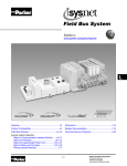
Pneumatic Division
Richland, Michigan USA
www.parker.com/pneumatics
Maintenance / Installation / Service Instruction Sheets
Click on bulletin below to view instruction sheet in PDF format.
Expansion Power Unit, PSSSE24A (24VDC)
Document Number
Description
E105P
Isysnet 24VDC Expansion Power Supply, Series A
PSS-SG001
Isysnet Serial Bus System Selection Guide
Installation & Service Instructions
E105P
Pneumatic Division
Richland, Michigan 49083
Isysnet 24VDC Expansion Power
Supply, Series A (PSSSE24A)
ISSUED: January, 2007
Supersedes: June, 2005
Doc.# E105P, ECN# 060961, Rev. 2
! WARNING
• To avoid unpredictable system behavior that can cause personal
injury and property damage:
• Disconnect electrical supply (when necessary) before installation,
servicing, or conversion.
• Disconnect air supply and depressurize all air lines connected to this
product before installation, servicing, or conversion.
• Operate within the manufacturer’s specified pressure, temperature,
and other conditions listed in these instructions.
• Medium must be moisture-free if ambient temperature is below
freezing.
• Service according to procedures listed in these instructions.
• Installation, service, and conversion of these products must be
performed by knowledgeable personnel who understand how
pneumatic products are to be applied.
• After installation, servicing, or conversion, air and electrical supplies
(when necessary) should be connected and the product tested for
proper function and leakage. If audible leakage is present, or the
product does not operate properly, do not put into use.
• Warnings and specifications on the product should not be covered by
paint, etc. If masking is not possible, contact your local representative
for replacement labels.
PSSSE24A
24VDC
Expansion
Power Supply
PSSSE24A
24V dc Power Supply
Wire
Marker
System
Power
Field
Power
Mini 7/8”
Power
Connector
LED
Indicators
P
AO
UW
XE
R
ATTENTION
Safety Guide
For more complete information on recommended application guidelines, see
the Safety Guide section of Pneumatic Division catalogs or you can download
the Pneumatic Division Safety Guide at: www.parker.com/safety
Introduction
Follow these instructions when installing, operating, or servicing the
product.
Isysnet 24VDC Expansion Power Supply,
Series A
!
Do not connect 120/240VAC to the PSSSE24A terminals.
Damage to the supply will result.
ATTENTION
!
You can only use the PSSSE24A expansion power unit with
the I/O adapters.
(PSSSE24A)
The 24VDC expansion power supply unit (PSSSE24A) passes 24VDC
field power to the I/O modules to the right of the power supply. This
unit extends the backplane bus power for up to 17 I/O modules to the
right of the supply and creates a new field voltage partition.
The expansion power supply also separates field power from I/O
modules to the left of the unit, effectively providing functional and
logical partitioning for:
• separating field power between input and output modules
• separating field power to the analog and digital modules
• grouping modules to perform a specific task or function
You can use multiple expansion power units with the I/O adapters
to assemble a full system. For instance, if you are using the
PSSCDM12A or PSSCDM18PA adapter, you may use a PSSSE24A
expansion power unit to add additional modules in 5 to 17 module
increments. For example, if you had a 36 module system with a I/O
adapter, you would have two PSSSE24A expansion power units
to provide more PointBus current for modules to the right of the
supply.
! WARNING
FAILURE OR IMPROPER SELECTION OR IMPROPER USE OF THE
PRODUCTS AND/OR SYSTEMS DESCRIBED HEREIN OR RELATED
ITEMS CAN CAUSE DEATH, PERSONAL INJURY AND PROPERTY
DAMAGE.
This document and other information from Parker Hannifin Corporation,
its subsidiaries and authorized distributors provide product and/or system
options for further investigation by users having technical expertise. It
is important that you analyze all aspects of your application, including
consequences of any failure and review the information concerning the
product or systems in the current product catalog. Due to the variety of
operating conditions and applications for these products or systems, the
user, through its own analysis and testing, is solely responsible for making
the final selection of the products and systems and assuring that all
performance, safety and warning requirements of the application are met.
The products described herein, including without limitation, product
features, specifications, designs, availability and pricing, are subject to
change by Parker Hannifin Corporation and its subsidiaries at any time
without notice.
EXTRA COPIES OF THESE INSTRUCTIONS ARE AVAILABLE FOR INCLUSION
IN EQUIPMENT / MAINTENANCE MANUALS THAT UTILIZE THESE PRODUCTS.
CONTACT YOUR LOCAL REPRESENTATIVE.
Isysnet 24VDC Expansion Power Supply, Series A (PSSSE24A)
Important User Information
ATTENTION
Solid state equipment has operational characteristics differing from
those of electromechanical equipment. Safety Guidelines for the
Application, Installation and Maintenance of Solid State Controls
(available online at www.parker.com/pneu/isysnet) describes some
important differences between solid state equipment and hard-wired
electromechanical devices. Because of this difference, and also
because of the wide variety of uses for solid state equipment, all persons
responsible for applying this equipment must satisfy themselves that
each intended application of this equipment is acceptable.
!
Environment and Enclosure
This equipment is intended for use in overvoltage Category
II applications (as defined in IEC publication 60664-1), at
altitudes up to 2000 meters without derating. This equipment
is considered Group 1, Class A industrial equipment according
to IEC/CISPR Publication 11. Without appropriate precautions,
there may be potential difficulties ensuring electromagnetic
compatibility in other environments due to conducted as well as
radiated disturbance. This equipment is supplied as “enclosed”
equipment. It should not require additional system enclosure
when used in locations consistent with the enclosure type
ratings stated in the Specifications section of this publication.
Subsequent sections of this publication may contain additional
information regarding specific enclosure type ratings, beyond
what this product provides, that are required to comply with
certain product safety certifications.
NOTE: See NEMA Standards publication 250 and IEC
publication 60529, as applicable, for explanations of the degrees
of protection provided by different types of enclosure. Also,
see the appropriate sections in this publication, as well as the
publication E115P (“Industrial Automation Wiring and Grounding
Guidelines”), for additional installation requirements pertaining
to this equipment.
In no event will Parker Hannifin Corporation be responsible or liable
for indirect or consequential damages resulting from the use or
application of this equipment.
The examples and diagrams in this manual are included solely
for illustrative purposes. Because of the many variables and
requirements associated with any particular installation, Parker
Hannifin Corporation cannot assume responsibility or liability for
actual use based on the examples and diagrams.
No patent liability is assumed by Parker Hannifin Corporation with
respect to use of information, circuits, equipment, or software
described in this manual.
Reproduction of the contents of this manual, in whole or in part, without
written permission of Parker Hannifin Corporation is prohibited.
Throughout this manual we use notes to make you aware of safety
considerations.
WARNING
!
Identifies information about practices or
circumstances that can cause an explosion in
a hazardous environment, which may lead to
personal injury or death, property damage, or
economic loss.
IMPORTANT
Identifies information that is critical for successful
application and understanding of the product.
ATTENTION
Identifies information about practices or
circumstances that can lead to personal injury
or death, property damage, or economic loss.
Attentions help you:
!
ATTENTION
!
Preventing Electrostatic Discharge
This equipment is sensitive to electrostatic discharge, which
can cause internal damage and affect normal operation. Follow
these guidelines when you handle this equipment:
•Touch a grounded object to discharge potential static.
•Wear an approved grounding wriststrap.
•Do not touch connectors or pins on component boards.
•Do not touch circuit components inside the equipment.
•If available, use a static-safe workstation.
•When not in use, store the equipment in appropriate staticsafe packaging.
• Identify a Hazard
• Avoid a Hazard
• Recognize the Consequence
SHOCK HAZARD
Labels may be located on or inside the
equipment to alert people that dangerous
voltage may be present.
BURN HAZARD
Labels may be located on or inside the
equipment to alert people that surfaces may
be dangerous temperatures.
E105P
2
Isysnet 24VDC Expansion Power Supply, Series A (PSSSE24A)
E105P
Mount the I/O Base
To mount the I/O base on a wall or panel, use the screw holes
provided in the base.
IMPORTANT
The I/O module must be mounted on a grounded metal mounting
plate or other conductive surface.
A mounting illustration for the base with an adapter is shown below.
1.9
(47.2)
2.0
(50)
0.87
(22)
2.0
(50)
3.13
(79.4)
5.98*
(151.9)
Adapter
2.39
(60.7)
4.02
(102)
4.32
(109.8)
1.81
(46)
Inches
(mm)
Drill and Tap
for M4 Screw
3.02
(76.6)
5.39
(137.0)
Drill and Tap
for M6 Screw
*Depending on the type and number of manifolds, this dimension
may vary. Refer to Catalog 0600P-# for additional information.
Install the Mounting Base as Follows:
1.Lay out the required points as shown above in the drilling
dimension drawing.
2.Drill the necessary holes for #8 (M4) machine or self-tapping
screws.
3.Mount the base using #8 (M4) screws.
4.Ground the system using the ground lug connection. (The ground
lug connection is also a mounting hole.)
Mounting Base
KeyswitchSet to position 1
for the PSSSE24A
dc expansion
power supply
Ground Lug
Connection
Latching Mechanism
3
Isysnet 24VDC Expansion Power Supply, Series A (PSSSE24A)
E105P
Install the 24VDC Expansion Power Supply
Wire the 24VDC Expansion Power Supply
To Install the Power Supply, Proceed as Follows:
1.Using a bladed screwdriver, rotate the keyswitch on the mounting
base clockwise until the number 1 aligns with the notch in the
base.
2.Position the power supply vertically above the mounting base.
The module will bridge two bases.
Following are wiring instructions for the 24VDC Expansion Power
Supply.
PSSSE24A
Module Will Bridge Two Bases
Male In Connector (Mini 7/8”)
(view into connector)
Pin 1-User Power +
Pin 2-Adapter Power +
PSSSE24A
24V dc Power Supply
Pin 3-Adapter Power Pin 4-User Power -
Note:User power is the 24VDC power for field devices.
Adapter power is the 24VDC power for PSSSE24A. It is
converted to 5VDC to power isysNet modules.
System
Power
Field
Power
P
AO
W
U
XE
R
ATTENTION
!
3.Push the power supply down until it engages the orange latching
mechanism. You will hear a clicking sound when the power supply
is properly engaged. The locking mechanism will lock the power
supply to the base.
Make sure all connectors and caps are securely tightened to
properly seal the connections against leaks and maintain IP67
requirements.
Remove the 24VDC Expansion Power Supply
From the Mounting Base
To Remove the Power Supply from the Mounting Base:
1.Put a flat blade screwdriver into the slot of the orange latching
mechanism.
2.Push the screwdriver toward the I/O module to disengage the
latch. The module will lift up off the base.
3.Pull the module off of the base.
Install a Replacement PSSSE24A to an
Existing System
1.Remove the module to the right of the power supply from the
mounting base.
2.If you have not done so already, remove the existing power supply
from the mounting base.
3.Position the replacement power supply vertically above the
mounting base.
4.Push the power supply down until it engages the orange latching
mechanism. You will hear a clicking sound when the power supply
is properly engaged and locked to the base.
5.Place the module to the right of the power supply back onto the
mounting base.
4
Isysnet 24VDC Expansion Power Supply, Series A (PSSSE24A)
E105P
Specifications
Following are specifications for the PSSSE24A Power Supply.
24VDC Expansion Power Supply - PSSSE24A
I/O Module Capacity
5 to 17 I/O modules depending on each module's current rating
Power Supply
adapter.
In order to comply with CE Low Voltage Directives (LVD), you must use a Safety Extra Low
Voltage (SELV) or a Protected Extra Low Voltage (PELV) power supply to power the
Inputs Voltage Rating
12VDC, 24VDC nominal
10-28.8VDC range
Operating Voltage
10-28.8VDC
Input Current, Maximum
6A for 10ms
Backplane Output Current
5VDC, 1.3A
Field Side Power Requirements, Maximum
24VDC (+20% = 28.8VDC) @ 400 mA
Indicators
1 Green Field Power Status Indicator
1 Green 5V System Power Indicator
Module Location
Between I/O modules in system
Breaks field power bus
PointBus Output Current
1A at 10-19.2V input; 1.3A at 19.2-28.8V input
Input Overvoltage Protection
Reverse polarity protected
Interruption
Output voltage will stay within specifications when input drops out for
10ms at 10V with maximum load
General Specifications
Power Consumption, Maximum
9.8W @ 28.8VDC
Power Dissipation, Maximum
3.0W @ 28.8VDC
Thermal Dissipation, Maximum
10.0 BTU/hr. @ 28.8VDC
Isolation Voltage
(continuous-voltage withstand rating)
50V rms
Tested at 1250VAC rms for 60s
Field Power Bus
Supply Voltage
Voltage Range
Supply Current
12VDC, 24VDC nominal
10-28.8VDC range
10A maximum
Dimensions
Inches (Millimeters) 1.25H x 2.63W x 4.25D (31.75H x 66.80W x 107.95D)
Operating Temperature
IEC 60068-2-1 (Test Ad, Operating Cold),
IEC 60068-2-2 (Test Bd, Operating Dry Heat),
IEC 60068-2-14 (Test Nb, Operating Thermal Shock):
-20 to 60°C (-4 to 140°F)
Storage Temperature
IEC 60068-2-1 (Test Ab, Un-packaged Non-operating Cold),
IEC 60068-2-2 (Test Bb, Un-packaged Non-operating Dry Heat),
-40 to 85°C (-40 to 185°F)
Relative Humidity
IEC 60068-2-30 (Test Db, Un-packaged Non-operating Damp Heat):
5-95% non-condensing
Shock
IEC60068-2-27 (Test Ea, Unpackaged Shock):
Operating 30g
Non-operating 50g
Vibration
IEC60068-2-6 (Test Fc, Operating):
5g @ 10-500Hz
ESD Immunity
IEC 61000-4-2:
6kV contact discharges
8kV air discharges
Radiated RF Immunity
IEC 61000-4-3:
10V/m with 1kHz sine-wave 80%AM from 30MHz to 2000MHz
10V/m with 200Hz 50% Pulse 100%AM at 900Mhz
10V/m with 200Hz 50% Pulse 100%AM at 1890Mhz
5
Isysnet 24VDC Expansion Power Supply, Series A (PSSSE24A)
E105P
General Specifications (continued)
EFT/B Immunity
IEC 61000-4-4:
±4kV at 5kHz on power ports
Surge Transient Immunity
IEC 61000-4-5:
±1kV line-line(DM) and ±2kV line-earth(CM) on power ports
Conducted RF Immunity
IEC 61000-4-6:
10Vrms with 1kHz sine-wave 80%AM from 150kHz to 80MHz
Emissions
CSPR 11:
Group 1, Class A
Enclosure Type Rating
Meets IP65/66/67 (when marked)
Mounting Base Screw Torque
#8 screw, 7.5 in. lbs. in Aluminum, 16 in. lbs. in Steel
Weight
Imperial (Metric) 0.637 lb. (0.289 kg)
Wiring Category 1 - on power ports
Keyswitch Position
1
Certifications: (when product is marked)
c-UL-us
1
UL Listed Industrial Control Equipment, certified for US and Canada
CE
European Union 89/336/EEC EMC Directive, compliant with:
EN 61000-6-4; Industrial Emissions
EN 50082-2; Industrial Immunity
EN 61326; Meas./Control/Lab., Industrial Requirements
EN 61000-6-2; Industrial Immunity
C-Tick
Australian Radiocommunications Act, compliant with:
AS/NZS CISPR 11; Industrial Emissions
1.Use this Conductor Category information for planning conductor routing. Refer to Publication E115P, “Industrial Automation Wiring and
Grounding Guidelines”.
6
Pneumatic
Isysnet
Serial Bus
System
Selection
Guide
Isysnet
The Isysnet System
Isysnet Features
Isysnet has four major components:
• Highly modular design (1pt — 8pt modularity)
• Valve driver module provide control for 32 solenoids
• Broad application coverage
• I/O modules provide the field interface, system-interface
circuitry, and bases for mounting
• Channel-level diagnostics (LED and electronic)
• Communication interface modules provide the networkinterface circuitry
• Channel-level open-wire detection with electronic feedback
• Power distribution module provide the solution to
expandability of the Isysnet system
• Channel-level alarm and annunciation (electronic)
• Channel-level short-circuit detection with electronic
feedback
• Parameter-level explicit messaging
• Removal and insertion under power (RIUP)
• DeviceNet™ expansion
• Horizontal and vertical mounting without derating
• 5g vibration
• Flash upgradable adapters and digital I/O
• Electronic and mechanical keying
• Robust backplane design
• Hot swapping of I/O modules
• Quick-disconnects for I/O and network connectivity
• Built-in panel grounding
• Color-coded module labels
• UL, C-UL, and CE certifications (as marked)
• Highly reliable structural integrity
• Optical isolation between field and system circuits
Publication PSS-SG001A-EN-P – June 2005
Isysnet 1
Isysnet Product Compatibiliy
The following chart illustrates the compatibility of Isysnet with other control platforms, especially with Rockwell Automation. For
information regarding the differences between the networks and Isysnet, please refer to the Selecting a Network Interface section
in this document.
DeviceNet
Adapter
PSSCDM
ControlNet
Adapter
PSSCCNA
EtherNet
Adapter
PSSCENA
PROFIBUS
Adapter
PSSCPBA
PLC-5™ with Network Port
IOD
NS
NS
NA
SLC 500™ with Network Port
IOD
NS
NS
NA
PLC-5 Processor via Network Module
IOD
NS
NS
3
1756 Logix™ Communication Interface
IOD
IOD
IOD
3
PanelView™ Terminal
NA
NA
NA
NA
RSLinx™ Software
NA
NA
NA
NA
1769-L20, -L30 Controller with
1761- NET Interface
NA
NS
NS
NA
1769-L35E
NA
NA
IOD
NA
SoftLogix5800™
NS
NS
NS
NA
PC with RSLinx Only
NS
NS
NS
NA
IOD = I/O Data
NS = Not Supported
NA = Not Applicable
3 = Requires third party scanner module
Communication Considerations
Isysnet features are impacted by your network choice.
Network
Impact
DeviceNet PSSCDM12A and
PSSCDM18PA
The PSSCDM12A and PSSCDM18PA provide two means of
connecting a node of I/O to DeviceNet.
A total of 63 Isysnet modules can be assembled on a single DeviceNet node.
Expansion power supplies may be used to provide additional PointBus backplane current.
ControlNet™ PSSCCNA
A total of 63 Isysnet modules can be assembled on a single ControlNet node.
Expansion power supplies may be used to provide additional PointBus backplane current.
Up to 25 direct connections and 5 rack connections are allowed.
EtherNet/IP™ PSSCENA
A total of 63 Isysnet modules can be assembled on a single EtherNet/IP node.
Expansion power supplies may be used to provide additional PointBus backplane current.
Refer to the User Manual, publication PSS-UM004 to determine the ratings for direct and
rack connections allowed.
PROFIBUS DP™ PSSCPBA
A total of 63 Isysnet modules can be assembled on a single PROFIBUS node.
Expansion power supplies may be used to provide additional PointBus backplane current.
Publication PSS-SG001A-EN-P – June 2005
2
Isysnet
Specifying an Isysnet System
Follow these steps as you specify your Isysnet system:
Step
1 Select a Communication Interface Module
See Page
NetLinx™ Architecture
2
Selecting a Network
3
Selecting the DeviceNet
Communication Interface
3
Location of the device
Digital I/O Modules
6
Number of Isysnet modules needed
Analog I/O Modules
7
Appropriate catalog number
Specialty I/O Module
9
Number of I/O available per module
Valve Driver Module
10
Expansion Power Unit
10
Typical Configurations
12
4 Select Accessories
Cables and Cordsets
13
5 Placing Isysnet Modules
Placing Isysnet Modules
15
Mounting the Isysnet System
16
Choose the interface module for your operating system.
2 Select I/O Devices Based on Field Devices
Number of modules
3 Select Optional Power Component
Choose optional component to extend backplane power
Determine necessary dimensions based on the
communication interface chosen.
Step 1 - Select a Communication
Interface Module
Selecting Isysnet Communication
Interfaces
Rockwell Automation NetLinx Architecture
Separate communication interface adapters are available for
different networks. Install adapters into the PointBus backplane
to allow Isysnet modules to communicate with a controller.
• EtherNet/IP is an open industrial networking standard that
supports implicit and explicit messaging and uses commercial,
off-the-shelf EtherNet equipment and physical media.
NetLinx open network architecture is the Rockwell Automation
strategy of using open networking technology for seamless,
top-floor to shop-floor integration. The networks in the NetLinx
architecture, DeviceNet, ControlNet, and EtherNet/IP, speak a
common language and share a universal set of communication
services. NetLinx architecture, part of the Integrated
Architecture, seamlessly integrates all the components in an
automation system from a few devices on one network to
multiple devices on multiple networks including access to the
Internet, helping you to improve flexibility, reduce installation
costs, and increase productivity.
• ControlNet allows intelligent, high-speed control devices to
share the information required for supervisory control, workcell coordination, operator interface, remote device
configuration, programming, and troubleshooting.
Publication PSS-SG001A-EN-P – June 2005
• DeviceNet offers high-speed access to plant-floor data from a
broad range of plant-floor devices and a significant reduction
in wiring.
Isysnet
3
Selecting a Network
You can configure your system for information exchange between a range of devices and computing platforms and operating
systems.
Application Requirements
Network
Select
EtherNet/IP
PSSCENA
ControlNet
PSSCCNA
• Plant management (material handling)
• Configuration, data collection, and control on a single,
high-speed network
• Time-critical applications with no established schedule
• Data sent regularly
• Internet/Intranet connection
• High-speed transfer of time-critical data between
controllers and I/O devices
• Deterministic and repeatable data delivery
• Media redundancy
• Controller redundancy
• Intrinsic safety
• Redundant controller systems
• Connections of low-level devices directly to
plant-floor controllers, without interfacing them
• Data sent as needed
PSSCDM12A
• More diagnostics for improved data collection and
fault detection
DeviceNet
PSSCDM18PA
PROFIBUS
PSSCPBA
• Less wiring and reduced start-up time than a traditional,
hard-wired system
• Connecting to an existing PROFIBUS DP 5m bus,
12 MB network
Selecting the DeviceNet Communication Interface
Isysnet offers two interfaces for connecting to DeviceNet. Refer to the following table.
For These Features
Remember
Select
• Behaves as a slave device on the Main
Network and a master on the PointBus
• All Isysnet modules count as a single
node on the Main Network
PSSCDM12A (M12-style network
connectors)
• Allows a group of I/O modules on the
Subnet to act as a single node on the
Main Network
• The Main Network distance
is acceptable
PSSCDM18PA (mini-style network
connectors with pass-through)
• RSNetWorx™ for DeviceNet software
is needed for configuration of the
PSSCDM12A or PSSCDM18PA
on the Main Network and the PointBus
• Isysnet expansion power supplies are
permitted to add more Isysnet modules.
• Configuration on the PointBus consists
of a scan list that is very similar to
those used in all of the DeviceNet
master scanner modules
Publication PSS-SG001A-EN-P – June 2005
4
Isysnet
With the introduction of the PSSS23A module, the amount of
data to be transferred over the Subnet could become
substantial. It is important that the total amount of data coming
from the Subnet does not exceed the data capability of either
the PSSCDM12A or PSSCDM18PA.
• 250 bytes (248 data + 2 bytes command info) for output data
(used as either COS, cyclic, or poll)
• 250 bytes (248 data + 2 bytes status info) for polled input
data
• 250 bytes (248 data + 2 bytes status info) for COS/cyclic
input data
• 8 bytes (6 data + 2 status info) for strobe input data
Publication PSS-SG001A-EN-P – June 2005
The data coming through the PSS adapter combined with the
other data from the Main Network cannot exceed the data
capability of the Main Network master scanner. If this occurs,
you will need multiple master scanners on the Main Network
and the I/O modules on the Subnet will need to be split
between multiple PSSCDM12A or PSSCDM18PA adapters.
Isysnet
5
Step 2 - Select I/O Modules
Selecting Isysnet Modules
Some modules have diagnostic features, electronic fusing, or
individually isolated inputs/outputs.
The Isysnet family provides a wide range of input and output
modules to span many applications, from high-speed discrete
to process control. Isysnet supports producer/consumer
technology, which allows input information and output status
to be shared among multiple Logix controllers.
PSST8M8A
24V dc Out
PSSCDM12A
PSSN8M12A
24V dc In
0
2
1
3
PSST8M12A
24V dc Out
0
2
1
3
PSSV32A
DeviceNet Out
Adapter
Status
DeviceNet In
0
0
2
6
x10
4
2
8
6
4
MOD
3
0
1
1
1
3
5
2
4
6
4
5
6
Net
0
2
4
Mod
NET
0
Adapter
Power
x1
MOD
NET
System
Power
PWR
MOD
NET
2
0
8
1
DeviceNet
Status
PointBus
Status
3
2
4
6
5
7
4
5
7
5
Fault
3
4
5
6
6
6
7
7
7
7
The Isysnet family of I/O modules includes:
• Digital I/O Modules
• Analog I/O Modules
• Specialty I/O Module
• Valve Driver Module
Publication PSS-SG001A-EN-P – June 2005
6
Isysnet
Digital I/O Modules
Digital DC Input Modules
Choose digital I/O modules when you need:
PSSN8M8A
PSSN8M12A
PSSN8M23A
PSSP8M8A
PSSP8M12A
PSSP8M23A
Number of Inputs
8 Sinking
8 Sourcing
Keyswitch Position
1
1
Voltage, On-State
Input, Nom.
24VDC
24VDC
- Logic circuits process the signal.
Voltage, On-State
Input, Min.
10VDC
10VDC
- An input LED turns on or off indicating the status of the
corresponding input device.
Voltage, On-State
Input, Max.
28.8VDC
28.8VDC
0.5 ms hardware
+ (0…65 ms
selectable)*
0.5 ms hardware
+ (0…65 ms
selectable)*
Current, On-State
Input, Min.
2 mA
2 mA
Current, On-State
Input, Max.
5 mA
5 mA
Current, Off-State
Input, Max.
1.5 mA
1.5 mA
PointBus Current
(mA)
75
75
1.0 W @ 28.8VDC
1.0 W @ 28.8VDC
• Input Modules. An input module responds to an input signal
in the following manner:
- Input filtering limits the effect of voltage transients caused
by contact bounce and/or electrical noise. If not filtered,
voltage transients could produce false data. All input
modules use input filtering.
- Optical isolation shields logic circuits from possible
damage due to electrical transients.
• Output Modules. An output module controls the output
signal in the following manner:
Input Delay Time,
ON to OFF
- Logic circuits determine the output status.
- An output LED indicates the status of the output signal.
- Optical isolation separates module logic and bus circuits
from field power.
- The output driver turns the corresponding output on or off.
• Surge Suppression. Most output modules have built-in
surge suppression to reduce the effects of high-voltage
transients. However, we recommend that you use an
additional suppression device if an output is being used to
control inductive devices, such as:
- Relays
- Motor starters
- Solenoids
Power Dissipation,
Max.
* Input ON-to-OFF delay time is the time from a valid input
signal to recognition by the module.
- Motors
Additional suppression is especially important if your
inductive device is in series with, or parallel to, hard
contacts such as:
Digital DC Output Modules
PSST8M8A
PSST8M12A
PSST8M23A
- Push buttons
- Selector switches
The digital I/O modules support:
• A wide variety of voltage interface capabilities
Number of Outputs
8 sourcing
Keyswitch Position
1
Voltage, On-State Output,
Nom.
24VDC
Voltage, On-State Output,
Min.
10VDC
Voltage, On-State Output,
Max.
28.8VDC
• Isolated and non-isolated module types
• Point-level output fault states
• Choice of direct-connect or rack-optimized communications
• Field-side diagnostics on select modules
Connector types are indicated by the catalog number. For
example, the PSSN8M12A has an M12 connector.
Publication PSS-SG001A-EN-P – June 2005
Output Current Rating, Max.
3.0 A per module, 1.0 A
per channel
PointBus Current (mA)
75
Power Dissipation, Max.
1.2 W @ 28.8VDC
Isysnet 7
Relay Output Module
PSSTR4M12A
Number of Outputs
4 Form A (N.O.) relays, isolated
Keyswitch Position
7
Output Delay Time,
ON to OFF, Max.
26 ms*
Contact Resistance,
Initial
30 mΩ
Current Leakage,
Off-State Output, Max.
1.2 mA and bleed resistor thru
snubber circuit @ 240V ac
PointBus Current (mA)
90
Power Dissipation, Max. 0.5 W
*Time from valid output off signal to relay deenergization by module.
Analog I/O Modules
The Isysnet analog modules support: on-board, channel-level
data alarming (four set-points per channel); scaling to
engineering units; channel-level diagnostics (electronic bits
and LEDs); and integer format.
• Over- and under-range detections and indications. This
eliminates the need to test values in the control program,
saving valuable processing power of the controller. In
addition, since alarms are handled by the module, the
response is faster and only a single bit per channel is
monitored to determine if an error condition has occurred.
• Ability to direct output device operation during an
abnormal condition. Each channel of the output module
can be individually configured to hold its last value or
assume a user-defined value on a fault condition. This
feature allows you to set the condition of your analog
devices, and therefore your control process, which may help
to ensure a reliable shutdown.
• Ability to individually enable and disable channels.
Disabling unused channels improves module performance.
• Selectable input filters This lets you select the filter
frequencies for each channel that best meets the
performance needs of your application based on
environmental limitations. Lower filter settings provide
greater noise rejection and resolution. Higher filter settings
provide faster performance. Note: The analog modules
provide four input filter selections.
• Selectable response to broken input sensor. This feature
provides feedback to the controller that a field device is not
connected or operating properly. This lets you specify
corrective action based on the bit or channel condition.
• High accuracy. The modules share a high accuracy rating
of ±0.1% of full-scale accuracy at 25 °C.
Choose analog I/O modules when you need:
• Individually configurable channels to use the module(s)
with a variety of sensors.
• On-board scaling to eliminate the need to scale the data in
the controller. Controller processing time and power are
preserved for more important tasks, such as I/O control,
communications, or other user-driven functions.
• On-line configuration. Modules can be configured in the
RUN mode using the programming software or the control
program. This allows you to change configuration while the
system is operating. For example, the input filter for a
particular channel could be changed, or a channel could be
disabled based on a batch condition. To use this feature, the
controller and network interface must also support this
feature.
Publication PSS-SG001A-EN-P – June 2005
8
Isysnet
Analog Input Modules
PSSNACM12A
PSSNAVM12A
Number of Inputs
2
2
Keyswitch Position
3
3
Input Signal Range
4…20 mA
0…20 mA
0…10V
±10V
Input Resolution, Bits
16 bits - over 21 mA
0.32 µA/cnt
15 bits plus sign
320 µV/cnt inunipolar or bipolar mode
Absolute Accuracy, Current Input
0.1% Full Scale @ 25°C*†
—
Absolute Accuracy, Voltage Input
—
0.1% Full Scale @ 25°C*†
Input Step Response, per Channel
70 ms @ Notch = 60 Hz (default)
80 ms @ Notch = 50 Hz
16 ms @ Notch = 250 Hz
8 ms @ Notch = 500 Hz
70 ms @ Notch = 60 Hz (default)
80 ms @ Notch = 50 Hz
16 ms @ Notch = 250 Hz
8 ms @ Notch = 500 Hz
Input Conversion Type
Delta Sigma
Delta Sigma
PointBus Current (mA)
75
75
Power Dissipation, Max.
0.6 W @ 28.8VDC
0.6 W @ 28.8VDC
* Includes offet, gain, non-linearity and repeatability error terms.
†
Analog input modules support these configurable parameters and diagnostics: open-wire with LED and electronic reporting; four-alarm and
annunciation set-points; calibration mode and electronic reporting; under- and over-range and electronic reporting; channel signal range and
update rate and on-board scaling; filter-type; channel update rate.
Analog Output Modules
PSSTACM12A
PSSTAVM12A
Number of Outputs
2
2
Keyswitch Position
4
4
Output Signal Range
4…20 mA
0…20 mA
0…10V
±10V
Output Resolution, Bits
13 bits - over 21 mA
2.5 µA/cnt
14 bits (13 plus sign)
1.28 mV/cnt inunipolar or bipolar mode
Absolute Accuracy, Current Output
0.1% Full Scale @ 25°C*†
—
Absolute Accuracy, Voltage Output
—
0.1% Full Scale @ 25°C*†
Step Response to 63% of FS,
Current Output
24 µs
—
Step Response to 63% of FS,
Voltage Output
—
20 µs
Output Conversion Rate
16 µs
20 µs
PointBus Current (mA)
75
75
Power Dissipation, Max.
1.0 W @ 28.8VDC
1.0 W @ 28.8VDC
* Includes offet, gain, non-linearity and repeatability error terms.
†
Analog output modules support these configurable parameters and diagnostics: open-wire with LED and electronic reporting (PSSTACM12A only);
fault mode; idle mode; alarms; channel signal range and on-board scaling.
Publication PSS-SG001A-EN-P – June 2005
Isysnet
9
Specialty I/O Module
PSSS23A
The PSSS23A serial-interface module offer a serial-link
communication interface solution for peripheral products with
RS-232 port.
The module allows a device with serial-interface output, i.e.,
bar code readers, to communicate up to 128 bytes of ASCII
data onto any network supported by Isysnet. Each module is
a single-channel, full-duplex interface and is rated for up to
38.4 kbaud. LED indicators on the module offer diagnostics
for the module, Isysnet PointBus backplane, and transmit/
receive status indication.
Isysnet ASCII Module Specifications
PSSS23A
Number of Serial Channels
1
Keyswitch Position
2 (Specialty)
PointBus Current (mA)
75
Power Dissipation
1.75 W @ 28.8VDC
Serial Port Parameters
Serial Character Framing
7N2, 7E1, 7O1, 8N2, *E1, 8O1, 7E2, 7O2
Serial Port Comm Speed
9600, 1200, 2400, 4800, 19.2 k, 38.4 k
Serial Port Receive from ASCII Device
Number of Receive Chars, Max
1...128
Receive Record Start Mode
No, exclude, include start delimiter
Receive Start Delimiter
ASCII character
Receive Record End Mode
No, exclude, include end delimiter
Receive End Delimiter
ASCII character
Send (Produce) on DeviceNet to Master
Receive String Data Type
Array, short-string, string
Pad Mode
Pad mode disabled, enabled
Pad Character
ASCII character
Receive Swap Mode
Disabled, 16-bit, 24-bit, 32-bit swap
DeviceNet Handshake Mode
Master/slave handshake, produce immediate
Produce Assembly Size
4...132
Serial Data Size
0...128 bytes
Receive Transaction ID
0...255
Serial Port Transmit to ASCII Device
Number of Transmit Chars, Max
1...128
Transmit End Delimiter Mode
No, exclude, include end delimiter
Transmit End Delimiter Character
ASCII
Consume on DeviceNet from Master
Consume String Data Type
Array, short-string, string
Transmit Swap Mode
Disabled, 16-bit, 24-bit, 32-bit swap
DeviceNet Record Header Mode
Transmit handshake/immediate
Consume Assembly Size
4...132
Serial Port Transmit/Explicit Messages from Configuration Tool
Transmit Serial Data String Size
0...128 bytes
Transmitted Serial Data Length
0...128 bytes
Transmit Transaction ID
0...255
Serial Port Status
TX FIFO overflow, RX FIFO overflow, RX parity error, handshake error, new data flag
Publication PSS-SG001A-EN-P – June 2005
10
Isysnet
Valve Driver Module
PSSV32A
The PSSV32A valve driver module provides an interface
between the Isysnet serial bus system and the Isys valve
assembly. This module will always be the last module on the
Isysnet serial bus. It controls 32 digital outputs at 24VDC.
Depending on the valve selection, it can control up to 32
single solenoid valves or 16 double solenoid valves.
Valve Driver Module Specifications
PSSV32A
Outputs per Module
32, sourcing
Voltage Drop, On-State Output, Maximum
0.2VDC
Voltage, Off-State Output, Maximum
28.8VDC
Voltage, On-State Output,
Maximum
Minimum
Nominal
28.8VDC
10VDC
24VDC
Output Current Rating
200 mA per channel, not to exceed 6.0 A per module
Output Surge Current, Maximum
0.5 A for 10 ms, repeatable every 3 seconds
Current Leakage, Off-State Output, Maximum
0.1 mA
Current, On-State Output Minimum
200 mA per channel
Output Delay Time OFF to ON, Maximum
1
Output Delay Time, ON to OFF, Maximum
1
0.1 ms
0.1 ms
External DC Power Supply Voltage Range
10 to 28.8VDC
External DC Power Supply Voltage Nominal
24VDC
1. OFF to ON or ON to OFF delay is time from a valid output “on” or “off” signal to output energization or de-energization.
Step 3 - Select the Appropriate Power Unit
Selecting a Power Supply Unit
Isysnet adapters have built-in PointBus power supplies. All Isysnet modules are powered from the PointBus by either an adapter
or expansion power supply.
Power Specifications
Cat. No.
Power Supply
Input Voltage,
Nom.
Operating
Voltage Range
Field Side Power
Reuirements,
Max.
Power Supply
Inrush Current,
Max.
Input
Overvoltage
Protection
Power Supply
Interruption
Protection
Reverse polarity
protected
Output voltage will
stay within
specifications when
input drops out for
max. load.
PSSCDM12A
PSSCDM18PA
PSSCCNA
PSSCENA
24VDC
10...28.8VDC
PSSCPBA
24VDC
(+20% = 28.8VDC)
@ 400 mA
PSSSE24A
Power units are divided into two categories:
• Communication adapters with built-in power supply (dc-dc)
• Expansion power supply
Publication PSS-SG001A-EN-P – June 2005
6 A for 10 ms
Isysnet
Expansion Power Unit
11
PSSSE24A Current Derating for Mounting
The PSSSE24A expansion power unit passes 24VDC field
power to the I/O modules to the right of it. This unit extends
the backplane bus power and creates a new field voltage
partition segment for driving field devices for up to 13 I/O
modules. The expansion power unit separates field power
from I/O modules to the left of the unit, effectively providing
functional and logical partitioning for:
1.3
1.0
Current
• Separating field power between input and output modules
• Separating field power to the analog and digital modules
Horizontal - 1 A @ (10-19.2V); 1.3 A @ (19.2-28.8V)
Vertical - 1 A @ (10-28.8V)
0.5
• Grouping modules to perform a specific task or function
You can use multiple expansion power units with any of the
communication adapters to assemble a full system. If you are
using the PSSCDM12A adapter, you may use a PSSSE24A
expansion power unit to add additional modules. For example,
if you had a 36 module system with a PSSCDM12A adapter,
you would have at least two or more PSSSE24A expansion
power units to provide more PointBus current for modules to
the right of the supply.
10
19.2
Voltage
28.8
• 24VDC to 5VDC converter
• 1.3A, 5VDC output (extend backplane power)
• Starts new voltage distribution
• Partitioning
Power Distribution General Specifications
PSSSE24A
Power Supply Requirements
Note: In order to comply with CE Low Voltage Directives (LVD), you must use a
Safety Extra Low Voltage (SELV) or a Protected Extra Low Voltage (PELV) power
supply to power this adapter
Field Side Power Requirements
24VDC (+20% = 28.8VDC max.) @ 400 mA
Inrush Current, Max.
6 A for 10 ms
Input Overvoltage Protection
Reverse polarity protected
Power Supply Interruption Protection
Output voltage will stay within specifications when input drops out for 10 ms at
10V with max load
Power Supply Input Voltage, Nom.
24VDC
Operating Voltage Range
10…28.8VDC
Power Consumption, Max.
9.8 W @ 28.8VDC
Power Dissipation, Max.
3.0 W @ 28.8VDC
Thermal Dissipation, Max.
10.0 BTU/hr @ 28.8VDC
Isolation Voltage
1250V rms
Field Power Bus Supply Voltage, Nom.
12VDC or 24VDC
Field Power Bus Supply Current, Max.
10 A
Publication PSS-SG001A-EN-P – June 2005
12
Isysnet
Typical Configurations
Power Distribution Options
Isysnet Communication Adapter and I/O Modules
24V Power
Supply
An auxiliary 24VDC power supply provides power to the PointBus backplane and I/O modules. You can connect up to 13 I/O
modules and an adapter with a maximum of 10 A field power, using the auxiliary power.
Isysnet System with 24VDC Expansion Power Unit (PSSSE24A)
PSSSE24A
24V Power
Supply
24V Power
Supply
The auxiliary power supports up to 13 I/O modules and an adapter with a maximum of 10 A field power. The 24VDC expansion
power unit (PSSSE24A) extends the backplane bus power to support up to 13 more I/O modules. Connect additional expansion
power units to expand the I/O assembly up to the maximum of 63 I/O modules.
Publication PSS-SG001A-EN-P – June 2005
Isysnet
13
Step 4 - Select Cables and Cordsets
Selecting Accessories
Cables and Cordsets
Isysnet Digital Input Module Cables
Catalog Number
For Using:
Recommended Rockwell
Automation Patchcord
(double-ended)
PSSN8M12A
PSSP8M12A
2 inputs per connector
879D-F4ACDM-x
879-C3AEDM4-5
1 input per connector
889D-F4ACDM-x
889D-M4AC-y
PSSN8M8A
PSSP8M8A
3-pin pico connectors
889P-F3ABPM-x
4-pin pico connectors
889P-F4ABPM3-x
—
889M-F12AHMU-z
889M-F12AH-y
For Using:
Recommended Rockwell
Automation Patchcord
(double-ended)
Recommended Rockwell
Automation Male
(single-ended)
2 inputs per connector
879D-F4ACDM-x
879-C3AEDM4-5
1 input per connector
889D-F4ACDM-x
889D-M4AC-y
3-pin pico connectors
889P-F3ABPM-x
4-pin pico connectors
889P-F4ABPM3-x
PSSN8M23A
PSSP8M23A
Recommended Rockwell
Automation Male Cordset
(single-ended)
889P-M3AB-y
x = length in meters (1, 2, 3, 5, and 10 standard)
y = length in meters (2, 5, and 10 standard)
z = length in meters (1, 2, and 3 standard)
For more cables and cordsets, please refer to www.connector.com
Isysnet Digital Output Module Cables
Catalog Number
PSST8M12A
PSST8M8A
889P-M3AB-y
x = length in meters (1, 2, 3, 5, and 10 standard)
y = length in meters (2, 5, and 10 standard)
For more cables and cordsets, please refer to www.connector.com
Isysnet Relay Output Module Cables
Catalog Number
Recommended Rockwell Automation
Patchcord (double-ended)
Recommended Rockwell Automation Male
Cordset (single-ended)
PSSTR4M12A
889D-F4ACDM-x
889D-M4AC-y
x = length in meters (1, 2, 3, 5, and 10 standard)
y = length in meters (2, 5, and 10 standard)
For more cables and cordsets, please refer to www.connector.com
Publication PSS-SG001A-EN-P – June 2005
14
Isysnet
Isysnet Specialty Module Cables
Catalog Number
Recommended Rockwell Automation
Patchcord (double-ended)
Recommended Rockwell Automation Male
Cordset (single-ended)
PSSS23A
889D-F4ACDM-x
889D-M4AC-y
x = length in meters (1, 2, 3, 5, and 10 standard)
y = length in meters (2, 5, and 10 standard)
For more cables and cordsets, please refer to www.connector.com
Isysnet DeviceNet and Auxiliary Power Cables
Recommended Rockwell
Automation Network Cable
Catalog Number
Network
KwikLink Flat Media system
standard drop cable:
1485K-PzF5-R5
PSSCDM12A
PSSCDM18PA
Recommended Rockwell
Automation Auxiliary
Power Cables
DeviceNet
Thin Round system standard
drop cable: 1485R-PzN5-M5
Standard Cordset (singleended): 889N-F5AFC-y
Thick Round system standard
drop cable: 1485C-PzN5-M5
Standard Patchcord (doubleended) 889N-F4AFNM-x
PSSCCNA
ControlNet
—
PSSCENA
EtherNet/IP
—
PSSCPBA
PROFIBUS DP
—
Standard Cordset (singleended): 889N-F5AFC-y
x = length in meters (1, 2, 3, and 6 standard)
y = length in feet (6, 12, and 20 standard)
z = length in feet (1, 2, 3, 4, 5, and 6 standard)
For more cables and cordsets, please refer to www.connector.com
Isysnet Valve Driver Module Harness Assemblies
Parker Kit Number
1 to 24 Outputs
25 to 32 Outputs
Isys HA and HB Valve
PS5624P
PS5632P
Isys H1, H2, and H3 Valve
PS4024P
PS4032P
Publication PSS-SG001A-EN-P – June 2005
Isysnet
15
Step 5 – Placing Isysnet Modules
Determining Mounting Requirements
The producer/consumer model multicasts messages. This
means that multiple nodes can consume the same data at the
same time from a single device. Where you place I/O modules in
the control system determines how the modules exchange data.
For a Rockwell controller to control Isysnet, the I/O must be:
• On the same network as the controller or
• On a ControlNet network that is local to that controller or
• On an EtherNet/IP network that is local to that controller
Maximum Size Layout
PointBus Current (mA)
Maximum I/O Modules
with 24VDC Backplane
Current at 75 mA each
Maximum I/O Modules
with Expansion
Power Supplies
Maximum Number of
I/O Module
Connections
1000
Up to 13
63
5 rack and 20 direct
PSSCDM12A on DeviceNet
PSSCDM18PA on DeviceNet
PSSCCNA on ControlNet
20 total connections
including rack and direct
PSSCENA on EtherNet/IP
PSSCPBA on PROFIBUS
PSSSE24A Expansion Power
Not to exceed scanner
capacity
Horizontal mounting:
1A@5Vdc for 10...19.2V
input; 1.3A @ 5VDC for
19.2...28.8V input
Vertical mounting:
1A @ 5VDC for
10...28.8V input
Power Supply Distance Rating
Modules are placed to the right of the power supply. Each
Isysnet module can be placed in any of the slots to the right of
the power supply until the usable backplane current of that
supply has been exhausted. An adapter provides 1 A current
to the PointBus. The PSSSE24A provides up to 1.3 A and I/O
modules require from 75 mA (typical for the digital and analog
I/O modules) up to 90 mA or more.
PointBus Current Requirements
Catalog Number
PointBus Current Requirements
PSSN8xxx
PSSP8xxx
75 mA
PSST8xxx
PSSTR4MRA
90 mA
PSSNACM12A
PSSTACM12A
75 mA
PSSNAVM12A
PSSTAVM12A
PSSS23A
75 mA
PSSV32A
Publication PSS-SG001A-EN-P – June 2005
16
Isysnet
Mounting the Isysnet System
You can panel mount the Isysnet system in the horizontal or
vertical orientation.
Isysnet with PSSCDM12A, PSSCDM18PA, PSSCCNA,
PSSCENA, PSSCPBA Mounting Dimensions
1.9
(47.2)
2.0
(50)
0.87
(22)
2.0
(50)
3.13
(79.4)
5.98*
(151.9)
Adapter
2.39
(60.7)
4.02
(102)
4.32
(109.8)
1.81
(46)
Inches
(mm)
Drill and Tap
for M4 Screw
3.02
(76.6)
5.39
(137.0)
Drill and Tap
for M6 Screw
* Depending on the type and number of manifolds, this dimension
may vary. Refer to Catalog 0600P-# for additional information.
Publication PSS-SG001A-EN-P – June 2005
Isysnet
17
Related Documentation
Additional user documentation presents information according to the tasks you perform and the programming environment you use.
Refer to the table below for information on Isysnet products.
Isysnet Related Publications*
Catalog Number
General Information
—
PSSN8xxx, PSSP8xxx, PSST8xxx
PSSTR4M12A
Pinout Wiring
Diagram
PSSNACM12A, PSSNAVM12A,
PSSTACM12A, PSSTAVM12A,
PSSS23A
PSSCDM12A, PSSCDM18PA,
PSSCCNA, PSSCPBA,
PSSCENA, PSSE24A
PSSCDM12A
PSSCDM18PA
Communication
Interfaces
PSSCCNA
PSSCENA
PSSCPBA
Valve Driver Module
PSSV32A
Description
Industrial Automation Wiring and
Grounding Guidelines
Safety Guidelines for the Application,
Installation and Maintenance of Solid
State Control
Pinout Guide for Isysnet Digital
I/O Modules
Pinout Guide for Isysnet
Relay Module
Pinout Guide for Isysnet Analog
and Serial Modules
Pinout Guide for Isysnet Adapters
and Power Supply
Isysnet DeviceNet Adapter
Module, Drop or Pass-through, with
male and female M12 connectors
Isysnet DeviceNet Adapter Module,
Drop or Pass-through, with male
and female M18 connectors
Isysnet Redundant ControlNet
Adapter Module
Isysnet Ethernet/IP 10/100 Mbps
Adapter Module
Isysnet PROFIBUS Adapter Module
32 Point Valve Driver Module
24VDC 8 Sink Input w/8 M8
PSSN8M8A
connectors
24VDC 8 Sink Input w/4 M12
PSSN8M12A
connectors, 2 points per connector
24VDC 8 Sink Input w/1 M23
PSSN8M23A
connector
24VDC 8 Source Input w/8 M8
PSSP8M8A
DC I/O
connectors
24VDC 8 Source Input w/4 M12
PSSP8M12A
connectors, 2 points per connector
24VDC 8 Source Input w/1 M23
PSSP8M23A
connectors
PSST8M8A
24VDC 8 Source Output w/1 M23
PSST8M12A
24VDC 8 Source Output w/4 M12
PSST8M23A
24VDC 8 Source Output w/8 M8
24VDC Analog Current Input
PSSNACM12A
w/ 2 M12 connectors
24VDC 2 Analog Voltage Input
PSSNAVM12A
w/ 2 M12 connectors
Analog
24VDC Analog Current Output
PSSTACM12A
w/ 2 M12 connectors
24VDC Analog Voltage Output
PSSTAVM12A
w/ 2 M12 connectors
Serial Interface
RS-232 ASCII Serial
PSSS23A
Module
Interface Module
Power Unit
PSSSE24A
24VDC Expansion Power Supply
4 From A isolated (normally open)
Relay Output
PSSTR4M12A
electromechanical relays
* Contact your local Parker distributor for information on ordering any of the above publications.
For electronic copies of these publications, go to: http://www.parker.com/pneu/isysnet
Publication Number
E115P
E116P
PSS-WD001
PSS-WD002
PSS-WD003
PSS-WD004
E101P, Installation Instructions
PSS-UM001, User Manual
E103P, Installation Instructions
PSS-UM003, User Manual
E104P, Installation Instructions
PSS-UM004, User Manual
E102P, Installation Instructions
PSS-UM002, User Manual
E100P
E106P
E107P
E110P
E111P
E112P
E105P
E109P
Publication PSS-SG001A-EN-P – June 2005
© Copyright 2005, Parker Hannifin Corporation. All Rights Reserved.
Trademarks not belonging to Parker Hannifin Corporation are the property of their respective companies.
Parker Hannifin Corporation
Pneumatic Division
8676 E. M89
P.O. Box 901
Richland, MI 49083 USA
Tel: (269) 629-5000
Fax: (269) 629-5385
Customer/Technical Service
Tel: (269) 629-5575
Fax: (269) 629-5385
Web site: www.parker.com/pneu/isysnet
E-mail:
[email protected]
Publication PSS-SG001A-EN-P – June 2005 Printed in U.S.A.