1
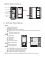
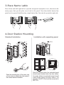
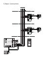
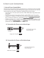
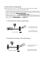
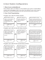
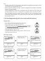
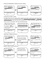
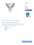
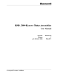
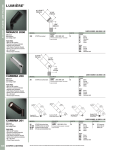
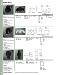
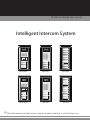
IP-MR11 USER MANUAL(EN) Intelligent Intercom System RF CARD MR11/ID/S4 MR11/D8 EP11/D24 MR11/S4 EP11/S12 RF CARD MR11/ID/D8 Read this manual carefully before using the product, and keep it well for future use. 1.Parts and Functions Camera Lens Infrared LED Camera Angle adjustment RF CARD Microphone 308 mm ID card window 298.5 mm Speaker Name plate Connection Port Call button 18 mm 123 mm 45 mm 114.5 mm 2. Terminal Descriptions 1 2 3 T/R+ T/R- PB PROG JWP P- P+ P+ PVD A1 JWV(OUT) D2 D1 NC JWB(OUT) JWP MD2 MD1 P- MA1 P- P+ VG VD P+ PVD A1 JWV(OUT) D2 D1 NC VG VD PROG PB JWB(OUT) MD2 MD1 P- MA1 EB+ EB N.O. LK+ LK +12V CN-LK PA MR11 JP-LK RS-485 1 2 3 T/R+ T/R- CN-LK PA EB+ EB N.O. LK+ LK +12V JP-LK RS-485 • CN-LK »» +12V: 12VDC power output. »» LK-(GND): power ground. »» LK+(COM): Common contact of the Relay . »» NO.: Normally open with LK+, can be configured to normally close through ST-Config »» EB+: Exit button connection port. »» EB-: Exit button connection port. • RROG »» D1: Data Receive. »» D2: Data Transmit.. »» A1: Audio signal. »» VD: Video signal. »» P+: Power positive(output). MR11 »» P-: Power negtive(output). • POWER »» P+: Power positive(input). »» P-: Power negtive(input). • RS485 »» T/R-: USB-RS485 communication terminal negative. »» T/R+: USB-RS485 communication terninal positive. »» PA: program button A(refer to program section). »» PB: program button B.(refer to program section). • JP-LK:For electronic lock safety type setting(refer to Door Station Lock Connections). 3.Place Name Lable Press down and shift right/left to open the tracsparent nameplate cover, then insert the name paper, then put the plate cover back to the panel. Note thar double button line panel can be opened both direction, single button line Can only be opened at right side Da vid Calo 4.Door Station Mounting Standard Installation Jointer*2 mm 298.5 mm 114.5 Installation with expanding panel 45 Stopper mm PB P+ PVD A1 JWV(OUT) D2 PROG JWP CN-LK PA MR11 JWB(OUT) EB+ EB N.O. LK+ LK +12V JP-LK RS-485 1 2 3 T/R+ T/R- D1 NC MD2 MD1 P- MA1 Open the mounting box of the panel, use a cross screw to adjust the view angle of the camera before installation. P- P+ VG VD Note:The double button line extended panel should match double button line door station; the single button line extended panel should match single button line door station. For example, the EP11/Dx should be connected to MR11/Dx . 5.Basic Connection to next floor GX-7P/C3/150 Distributor D2 D1 PA1 PP+ GND VD A B E F Monitor to monitors TEST P.341X GX-7P/C3/150 Distributor D2 D1 PA1 PP+ GND VD A B E F to monitors TEST P.341X PB JWB(OUT) JWP MD2 MD1 P- MA1 P- P+ VG VD Power supply + - 220 V Exit button + - 12V 300mA PROG P+ PVD A1 JWV(OUT) D2 D1 NC CN-LK PA MR11 EB+ EB N.O. LK+ LK +12V JP-LK RS-485 1 2 3 T/R+ T/R- RF CARD Monitor 6.Door Lock Connections 1. Internal Power Supply Mode Use the power of the system to supply for the electronic lock, so that the lock can be connected to the door station directly, without an additional power supply for the electronic lock. Note that the door station can only output 12Vdc power, therefore the kind of lock is limited. • The rated power of the lock must be less than 12Vdc 300mA when using internal power supply mode • The GND must connect to the negative of the lock, and the COM connect to the positive . • Jumper set to 2-3 position for Power-off-to-Unlock safety type(Normally closed mode); set to 1-2 position for Power-on-to -Unlock type(Normally open mode ). • If different unlocking time is needed to be configured, the ST-CONFIG software can be used to change the Unlock Timing on the Parameter tab(for more detail information ,please refer to ST-CONFIG software user manual). A. Connection for Power-on-to-Unlock type: +12V LK - (GND) LK+(COM) N.O. EB+ EB - + 3 2 1 12V 300mA set to Normally open on the Unlock Relay mode Jumper set to 1-2 position JP_LK B. Connection for Power--off-to-Unlock type: +12V LK - (GND) LK+(COM) N.O. EB+ EB - - 12V 300mA Jumper set to 2-3 position 3 2 1 + JP_LK set to Normally Closed on the Unlock Relay mode 2. External Power Supply Mode When the electronic lock is over 12 Vdc, additional power supply for the lock is needed. • The power supply for the lock must be less than 48Vdc 1.5A. • The Jumper must be removed when using external power supply. The default setting is Power-on-to-Unlock type(Normally open mode), if use Power-off-to-Unlock type, change the Unlock Relay mode to Normally closed mode . • If different unlocking time is needed to be configured, the ST-CONFIG software can be used to change the Unlock Timing on the Parameter tab(for more detail information ,please refer to ST-CONFIG software user manual). C. Connection for Power-to-Unlock type: + +12V LK - (GND) LK+(COM) N.O. EB+ EB - + Remove the Jumper 3 2 1 - set to Normally Open on the Unlock Relay mode (default) Note: Cut off this line when using external power supply JP_LK D. Connection for Power--off-to-Unlock type: - + - Remove the Jumper +12V LK - (GND) LK+(COM) N.O. EB+ EB 3 2 1 + JP_LK set to Normally Closed on the Unlock Relay mode Note: Cut off this line when using external power supply 6.Door Station Configurations 1. About room code(address): Room code(also called room address) is a code assigned to each monitor, to identify different monitors; each monitor have a unique room code in one buidling.The room code is stored in each Monitor’s inner EEPROM memory, and it won't be lost even the monitor is power off. 2. User Code Programming: Program user code for master monitor: Press PA button on door station in normal mode to enter program mode. All LED indicator will be shut off. beep+,beep+ Press CALL button on monitor or Audio Phone which is assigned to program beep+,beep Press a call button on door station in one time within 2s.the selected call button indicator will be turned on,the monitor will be programmed with a user code. beep+ Program user code for the first slave monitor: Press PA button on door station in normal mode to enter program mode. All LED indicator will be shut off. beep+,beep+ Press CALL button on monitor or Audio Phone which is assigned to program beep+,beep Continuously press the call button which is the same as programmed for master monitor on door station in twice within 2s.the selected call button indicator will be turned on,the first slave monitor will be programmed with a user code as the same as the master monitor. beep+,beep+ Program user code for the second slave monitor: Press PA button on door station in normal mode to enter program mode. All LED indicator will be shut off. beep+,beep+ Press CALL button on monitor or Audio Phone which is assigned to program beep+,beep Continuously press the call button which is the same as programmed for master monitor on door station in 3 times within 2s.the selected call button indicator will be turned on,the first slave monitor will be programmed with a user code as the same as the master monitor. beep+,beep+,beep+ Note: • The door station will exit out the program mode wether the programming is success or not.all LED indicators will be recovered to turn on. • Please repeat the operation from step 1 to step 3 to program the next monitor or next Audio Phone(or the slave monitors) • During programming,if there isn't any operation within 60s when the CALL button has not been pressed on monitor or there isn't any operation within 10s when the CALL button has been pressed on monitor.The door station will exit out the program mode automatically."beep,beep,beep" will be sent out from door station,and all LED indicators will be recovered to turn on. 3. ID Card Registration(just for the model with ID function): Introduction: •• Up to 1000 user cards can be registered by the door station. •• Easy management with LED status and sound hints. •• There are two master cards, one MASTER CARD ADD card and one MASTER CARD DELETE card, When registered new master cards, the old master cards are invalid automatically. •• Card reading distance is from 3 to 5 cm. •• The master cards are necessary when you add or delete user cards. Please keep it well for future use. Add User Cards: Show the MASTER CARD ADD card to ID card window in standby mode. beep+,beep Show user cards to be added, one by one. beep+ Show the MASTER CARD ADD card to exit. But it will return to standby mode if no operation within 15s. beep,beep+ Delete User Cards: Show the MASTER CARD DELETE card to ID card window in standby mode. Show user cards to be deleted in sequence. beep+,beep beep+ Show the MASTER CARD DELETE card to exit.But it will return to standby mode if no operation within 15s. beep,beep+ Access Initialization (delete all user cards): Show the MASTER CARD DELETE card to ID card window in standby mode. Show the MASTER CARD ADD card to ID card window. beep+,beep+ beep+ Show the MASTER CARD ADD card to ID card window again,format operation is performing. beep,beep, beep,beep, beep+ Authorize master cards: By default,there are two master cards marked MASTER CARD ADD and MASTER CARD DELETE ,but you should know that the master card can be authorized by users at any time.That means any two user cards can be authorized to master cards,When registered new master cards, the old master cards are invalid automatically. When the door station is in standby, press PA button and hold for 3 seconds to get into the master card manage state. The first card shown is the MASTER CARD ADD card,it will return to standby if no operation within 10s. beep+,beep beep+ The second card shown is the MASTER CARD DELETE card,it will return to standby if no operation within 10s. beep+ Add User Cards by Room: Show the MASTER CARD ADD card to ID card window in standby mode. Press a call button on door station, then show the user cards to be added for the room which to be assigned. beep+,beep beep+ Show the MASTER CARD ADD card to exit. But it will return to standby mode if no operation within 15s. beep,beep+ Delete User Cards by Room: Show the MASTER CARD DELETE card to ID card window in standby mode. beep+,beep Press the call button on door station which is authorized to the room. beep+ Show the MASTER CARD DELETE card to exit.But it will return to standby mode if no operation within 15s. beep,beep+ Card management soud hints State Operation standby state Card management state Sound hint show user card(registered) a long 'beep+' (door open) show user card(not-registered) beep, beep ,beep Enter the card management state beep+, beep Exit out the card management state beep ,beep Add card/Delete card/Format successful beep+ Add a already existed card beep+, beep+ Add card/Delete card/Format unsuccessful beep, beep, beep Add a debug card(16666666) beep, beep ,beep, beep Add card failure (1000 cards registered) beep, beep ,beep, beep, beep Card management LED hints State LED-A LED-B LED-C LED-D Standby ON ON ON ON Authorize ADD-Card ON OFF OFF ON Authorize DELETE-Card OFF ON OFF ON Add user card ON OFF OFF OFF LED-D Delete user card OFF ON OFF OFF LED-B Format ON ON OFF OFF RF CARD LED-C LED-A MR11/ID/D8 7.Monitor Online Search Search the monitors controlled by the right row buttons Press PB button on door station in normal mode to activate searching monitors controlled by the right row buttons. All LED indicator will blink twice,then turn off.Monitor online search is starting. -If the monitor is online,the indicator of the corresponding button will light up and send out soud of "beep". -If the monitor is not online,the indicator will not light up and send out soud of "beep,beep,beep". Search the monitors controlled by the left row buttons Press PB button and hold for 3s on door station in normal mode to activate searching monitors controlled by the left row buttons. All LED indicator will blink twice,then turn off.Monitor online search is starting. -If the monitor is online,the indicator of the corresponding button will blink twice,then light up. and send out soud of "beep". -If the monitor is not online,the indicator will not light up and send out soud of "beep,beep,beep". Note: • After all monitors had been searched, the indicators of the corresponding buttons for all online monitors will blink twice, then light up.and send out soud of "beep".then the door station will exit out the search mode automatically. • During searching,press the PB button on door station to exit manually. 8.Specification ●● Power supply: DC 18~24V ●● Camera Lens 1/3 inch color CCD ●● Power consumption: Standby 0.5W; Working status 15W ●● Video signal: 1Vp-p, 75Ω, CCIR standard ●● Unlock Power output: 12Vdc 300mA ●● NO, COM exchange contact: Max. 48V dc 1.5A ●● Monostable relay activation time: 1 second to 10 minutes ±5% ●● Working temperature: -5ºC +45ºC ●● Wiring: 6 wires, polarity ●● Dimension: 313(H)x128(W)x63(D)mm The design and specifications can be modified without notice to the user. Right to interpret and copyright of this manual are preserved. Printed In China / 2011. 11