1
CONNECTIONS, CONTROLS and INDICATORS
TEN AMP POWER BOOSTER
POWERHOUSE
FROM
NCE Corporation
CONTROL BUS
NORMAL
POWER
POWER
STATUS
TRACK
LOOP
22VAC/32VDC MAX.
PB110A
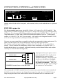
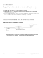
Starting at the left side of the front panel, each terminal, socket, switch and indicator is explained
below:
POWER connector
The Recommended input power for the PB-110A is 16-22 volts AC or 24-32 volts DC. The
supply must be capable of supplying about 10 to 12 Amps (180-250VA) to get full output from
the booster. We recommend the Hammond Manufacturing model 165T22. This is a 22 volt 12
Amp transformer. It is also sold as Allied Electronics part number 836-6185. (Allied phone
number is 1-800-433-5700 MC/Visa accepted). Also usable is the Magnetek model F-259U,
a 20 volt 10 Amp transformer (Allied part number 967-8442).
Do not a use power supply that can supply less than the recommended voltage and current. If a
short circuit develops on the layout the PB110A will not be able to protect itself.
The absolute maximum input voltage is 24 Volts AC or 36 volts DC. Do not exceed these
ratings! Always measure the transformer voltage before connecting it to your PB-110A. A
booster that has been ‘over voltaged’ will almost certainly result in booster failure and void the
warranty (we can tell if this has happened).
POWER WIRE
POWER WIRE
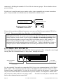
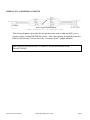
POWER Connections to the PB110A
Input power from your power source
goes into the PB-110A via the screw
terminals of the green (or black)
POWER connector. One power wire
should go to the left two terminals
and the other power wire should go to
the right two terminals. This is to
make sure the “per pin” power rating of
the connector is not exceeded.
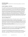
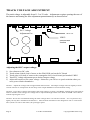
We recommend #14 AWG stranded wires for connection to power but the screw terminals of
the black (or green) connectors are designed to accept wires only up to #16 AWG (1.3mm).
Strip and prepare forked wire ends as shown below for insertion in to two terminals of the
Last Revised 03/05/01
Copyright 2000 NCE Corp.
Page 3