1
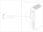
Radiant Version 2.0 April 2014 User Guide PlexBright™ 4 Channel Optogenetic Controller with Radiant™ Software Part of the PlexBright Optogenetic Stimulation System Plexon Inc 6500 Greenville Avenue, Suite 700 Dallas, Texas 75206 USA CAUTION THIS OPTOGENETIC CONTROLLER IS NOT FOR USE IN HUMANS. CAUTION READ THE ENTIRE MANUAL BEFORE ATTEMPTING TO OPERATE THIS EQUIPMENT. CAUTION In LED mode the output of the PlexBright 4 Channel Optogenetic Controller can range up to 12V. This high compliance voltage makes it possible to drive several LEDs in series from one controller output channel. Some external devices may be damaged by the voltages the controller can generate. Exercise caution when connecting the PlexBright 4 Channel Optogenetic Controller output to other devices to avoid inadvertently applying voltages up to 12V to those devices. CAUTION The output of some PlexBright 4 Channel Optogenetic Controllers can temporarily go to 12V when the Radiant software is launched. Specifically, this glitch occurs when revision blank controllers built prior to Nov 21st 2013 (PN 08-06-A-04) are switched from Laser mode (voltage output) to LED mode (current output). When the Radiant software starts up, the controller always switches from Laser mode to LED mode. Thus the glitch to 12V always occurs in revision blank controllers when the Radiant software is launched. You can determine the revision of the controller by looking at the label on the bottom of the controller or by looking in the Radiant 2.0 software under the info section for each controller. The Radiant software will also provide a warning dialog on startup if the affected hardware is detected. This glitch has been eliminated from PlexBright 4 Channel Optogenetic Controllers starting with revision A (PN 08-06-A-04-A). If you have a revision blank controller, you may return it to Plexon for modification to revision A. Contact Plexon support at +1 214-369-4957 or [email protected] for information and instructions. PlexBright™ 4 Channel Optogenetic Controller with Radiant™ Software Part of the PlexBright Optogenetic Stimulation System User Guide Document number: OPTMN0002b Document status: Standard Software version: Radiant Version 2.0 Date: April 2014 Copyright © 1983-2014 Plexon Inc, All Rights Reserved Printed in the United States of America Plexon Inc Proprietary The information contained herein is the property of Plexon Inc and it is proprietary and restricted solely to assist Plexon Inc customers. Neither this document nor the contents may be disclosed, copied, revealed or used in whole or in part for any other purpose without the prior written permission of Plexon Inc. This document must be returned upon request of Plexon Inc. Information is subject to change without notice. Plexon Inc reserves the right to make changes in equipment design or components as progress in engineering or manufacturing may warrant. PLEXON®, the five-line symbol, Plexon Inc, CereStage™, CinePlex®, DigiAmp™, MiniDigi™, Offline Sorter™, OmniPlex®, PL2™, PlexBright™, PlexDrive™, PlexStim™, Radiant™, RapidGrid™ and the Plexon logo are trademarks of Plexon Inc, Dallas, Texas, USA. Other product and company names mentioned are trademarks of their respective owners. ii Radiant Version 2.0 Plexon Inc Plexon Inc iii Publication History April 2014 In Section 1, added hardware part number 08-06-A-04-C. In Section 11, changed voltage output accuracy from ±10mV, ±1% to ±18mV, ±2%. In section 11 in the second row (Weight), changed “stimulator” to “controller” and changed 1.2 lbs to 1.1 lbs. Updated the cross-references to the cautions on the inside front cover of the document. December 2013 Added pattern generation and licensing, and updated hardware. Updated images, screenshots and illustrations accordingly. December 2012 This is the first release of the manual. PlexBright 4 Channel Optogenetic Controller with Radiant iv Radiant Version 2.0 Plexon Inc Plexon Inc v Contents Publication History PlexBright™ 4 Channel Optogenetic Controller with Radiant™ Software Before You Begin 1-2 Introduction 1-3 System Requirements 1-4 System Components 1-5 Installation 1-7 Getting Started 1-14 GUI Function Reference 1-28 Input and Output Connectors 1-33 Sample Arbitrary Waveform Pattern Files Optogenetic Controller Limitations 1-38 Specifications 1-41 1-37 PlexBright 4 Channel Optogenetic Controller with Radiant vi Radiant Version 2.0 Plexon Inc PlexBright™ 4 Channel Optogenetic Controller with Radiant™ Software Radiant Version 2.0 1 1 Before You Begin Before using your system, please check www.plexon.com/downloads.html for any software updates. PlexBright™ 4 Channel Optogenetic Controllers manufactured prior to November 21, 2013 are eligible for a no charge upgrade to revision A. You can determine the revision of the controller by looking at the label on the bottom of the controller or by looking in the Radiant software under the info section for each controller (Radiant Version 2.0 and later). Please see the caution on the inside front cover. Contact Plexon support at +1 214-369-4957 or [email protected] for additional information. The information in this user guide refers to: 2 • Hardware PN 08-06-A-04, 08-06-A-04-A, 08-06-A-04-B and 08-06-A-04-C • Firmware PN 08-06-A-32 • Radiant software Version 2.0 PlexBright 4 Channel Optogenetic Controller with Radiant 2 Introduction The PlexBright 4 Channel Optogenetic Controller is a 4-channel current output (LED mode) or voltage output (Laser mode) device. It has 4 individually programmable channels that can be configured from a host computer using the Radiant graphical user interface software or configured from user-written applications by means of a software development kit (SDK). In LED mode the controller can output up to 1100mA from each channel and the compliance voltage can range up to 12V to drive multiple LEDs in series. In Laser mode the controller can output voltages from 0 – 5V for modulating the output of a Laser or other device. User defined output limits may be defined with 8-bit precision and output waveforms may be defined with 8-bit resolution within those output limits. Playback of pulses and arbitrary stimulation waveforms may be initiated from the host PC or triggered in response to external digital inputs. Each channel has a dedicated start and stop digital input that may be used to initiate and halt stimulation. Each channel also has four dedicated digital outputs to signal to other devices the precise time when stimulation events are occurring. The Radiant 2.0 graphical user interface incorporates a new Pattern Generator tool that allows you to quickly define complex output patterns for the PlexBright 4 Channel Optogenetic Controller to play back. Arbitrary stimulation patterns can also be loaded from user defined text files or the outputs can be controlled directly by the user in manual mode. Thank you for purchasing this Plexon product. We hope you are pleased with every aspect of it. Please do not hesitate to contact us if you have any questions. Radiant Version 2.0 3 3 System Requirements A modern personal computer running Windows 7 or Windows XP with a free USB 2.0 port and 1 GB of memory is required to operate the system. 4 PlexBright 4 Channel Optogenetic Controller with Radiant 4 System Components When you receive your PlexBright 4 Channel Optogenetic Controller, confirm that you have the following pieces: 1 USB memory with software and drivers (in box) Plexon 2 AC power cord (7.5 ft)* Volex 17250 10 B1 3 Power Supply Plexon 08-06-A-37 4 USB Cable (2m) Monoprice 5438 5 Optogenetic Controller Plexon 08-06-A-04 6 License Key (in software box) Plexon 7 Color-coded Insulated BNC Cables (4) Plexon 06-03-A-04-CCLL * International customers: The stimulator power supply has an International Electrotechnical Commission (IEC) 60320 C14 inlet for AC power (shown below). The AC power cord supplied with the stimulator has an IEC 60320 C13 connector and a NEMA 5-15 plug compatible with the AC wall outlets in North America. Users in other regions must supply a power cord with an IEC 60320 C13 connector and a plug that is compatible with the AC wall outlets in the region of use. The hardware and cables are shown in the following photograph. Radiant Version 2.0 5 6 PlexBright 4 Channel Optogenetic Controller with Radiant 5 Installation Read the entire installation section before proceeding with the installation. Follow the installation steps in the order that they are presented. Install the software first, followed by the hardware. Do not connect the controller to an implant until you have read the entire manual. 5.1 Software Installation Read the entire Software Installation section before proceeding with any of the steps. 1 Browse to the \PLEXON_SW\RadiantV2\x64 or \x86 folder on the USB flash drive depending on if you have a 64 or 32 bit operating system 2 Right-click the file Radiantx86V2Setup.exe or Radiantx64V2Setup.exe and select Run as Administrator to begin the installation process. On some computers, you will get a warning 3 Click Yes or Run to continue. The welcome screen appears: If the software is already installed, then the welcome screen gives you the option to repair (re-install) or remove the software as shown on the right above. If the software is not already installed, then the welcome screen shown above on the left appears. Click Next to continue. Radiant Version 2.0 7 4 Read and accept the Plexon End User License Agreement Click Next to Continue 5 You will be asked to confirm where the files will be stored: Click Next to Continue 6 8 When the installation begins, it may take a couple of minutes before the progress bar begins moving across the window. This is especially true in Windows 7: PlexBright 4 Channel Optogenetic Controller with Radiant 7 An Opal Kelly FrontPanel USB Driver Setup window will pop up. Click Next. 8 Accept the Opal Kelly License Agreement 9 Click Finish When the Opal Kelly Driver Setup is complete. Radiant Version 2.0 9 10 Sentinel System Drivers will install for the license key. In some cases, Windows XP may need to restart before it can install these drivers. 11 Click Finish in the Plexon Radiant installation window 12 Restart the computer to complete the installation. 10 PlexBright 4 Channel Optogenetic Controller with Radiant 5.2 Hardware Installation Read the entire Hardware Installation section before proceeding with any of the steps. An oscilloscope is highly recommended for viewing the output of the channels in voltage mode. 1 Connect the AC power cord between the AC outlet and the power supply. 2 Connect the DC power cord between the power supply and the PlexBright 4 Channel Optogenetic Controller. 3 Connect the USB cable between the PlexBright 4 Channel Optogenetic Controller and the computer. 4 Connect the BNC cable between the PlexBright 4 Channel Optogenetic Controller channel 1 and the Oscilloscope. Radiant Version 2.0 11 5.3 Turning on the Power for the First Time 1 Flip the power switch to the on position. The LED next to the switch on the end of the PlexBright 4 Channel Optogenetic Controller should illuminate. 2 The first time you turn the stimulator on a “Found New Hardware” balloon will appear in the lower right hand corner of the computer screen. In Windows 7, the balloon changes from “Installing device driver software” to “Opal Kelly XEM6001”. In Windows XP, the Found New Hardware Wizard will appear. Choose Install the software automatically. After it is finished, the balloon will change to “Your new hardware is installed and ready to use.” The following diagram shows the dialog boxes for this process. 12 PlexBright 4 Channel Optogenetic Controller with Radiant Windows 7: Windows XP: The first time that you plug in the USB license key you will see an installation message as well. Radiant Version 2.0 13 6 Getting Started This section introduces the basic functions of the PlexBright 4 Channel Optogenetic Controller and guides you through basic operation using the voltage mode. Voltage mode is intended to be used to control lasers with a 0-5V control input The current mode functions similarly for controlling LEDs, but it is more difficult to quantify the output without a light meter. It is highly recommended that you work through this section before attempting to do any type of stimulation. Note that you will need an oscilloscope to see the output. 6.1 Overview Every optogenetic stimulation protocol begins with the definition of the stimulation pattern. The graphical user interface (GUI) provides a means for manually setting the output value, creating a stimulation with the pattern generator, or loading a stimulation pattern from a user-created text file. Once defined, the stimulation pattern is downloaded into the controller memory for playback. Playback can be initiated from the GUI, SDK, or in response to a digital input to the controller hardware. 14 PlexBright 4 Channel Optogenetic Controller with Radiant 6.2 Operational Flowchart Radiant Version 2.0 15 6.3 Launching the Radiant Software Make sure all of the PlexBright 4 Channel Optogenetic Controllers are connected to the computer and turned on. Up to four controllers can be used with a single computer. Then launch the Radiant software by double clicking on the RadiantV2 desktop icon. You should see the factory default graphical user interface as shown in the figure below. Note that the number of controllers that are connected will determine the number of tabs in the bottom left of the screen. If multiple controllers are connected but their tabs do not show up, they can be added by from the View drop down in the menu bar. Also, the LEDs on the end panel of the controller will indicate the device number 1~4. TIP Restoring factory settings You may load the factory default configuration at any time by clicking File – Restore Factory Settings. Note that if the USB cable is not connected to the controller or if the controller power is turned off when the software is started, the software will open the pattern generator only, as seen in the image below. There will be no window for configuring stimulation channels. 16 PlexBright 4 Channel Optogenetic Controller with Radiant If you see the window like the one shown below, and your stimulator is connected, it is possible that your layout has changed. Go to Window – Layout – Reset to Default Layout. Radiant software requires a USB license key to be operated. If the key is not plugged into the computer, you will see the following warning. 6.4 Using Manual Mode to Operate the Controller The fastest and easiest way to use the controller is in manual mode. This is the mode that the software will start in by default the first time the software is run. If it is not in manual mode, you can select it by clicking the drop down menu next to Pattern Source. Radiant Version 2.0 17 Begin by using a BNC cable to connect the output marked CH 1 to an oscilloscope. Next, set the Output Device to Laser and the Voltage Limit to 5000mV. Then click in the box below Manual Mode to and move the slider to 1000 (mV). TIP Fine tuning the slider value Fine incremental changes can be made to the slider value using the up and down arrow keys or the scroll wheel on your mouse. When you press the start button for channel 1 in the upper left, the output voltage will change to 1V and the green triangle will change to a red square. Ready to Start Ch. 1 Playing Once the channel is running, you can adjust the slider to change the output voltage. The output will remain at the set voltage until you stop the channel or change the value. 6.5 Starting and Stopping Stimulation There are two ways to start playing a stimulation pattern: with the host PC through software and with a hardware digital input. Note that a pulse started from software can be stopped with a digital input and vice versa. In software, until a pattern for a channel has been defined, the start button in the top left of the interface is grayed out. As soon as the pattern has been selected, the start button becomes active. At that point, the channel can be triggered to start. To initialize stimulation from the software, you can click the start button for the individual channel. Alternatively, the start all button (to the right of channel 4’s start button) can be clicked and every channel of that controller that has been configured will start at the same time. Once clicked, the start button changes functionality to become a stop button. 18 PlexBright 4 Channel Optogenetic Controller with Radiant In hardware there are start and stop TTL-compatible digital inputs for each channel. Inputs should range from 0 – 5 V. Inputs <0.8V are logic “0” and >2.0V are logic “1”. The pinout for the Digital In connector is shown below. The digital inputs can be operated in two different modes. To select the mode, click the drop down menu next to DI Mode at the top of the screen. The first mode is called Edge mode. In this case, a rising edge on the start pin initiates stimulation, and a rising edge on the corresponding stop pin stops stimulation. If the stop input comes in the middle of a stimulation pattern, the pattern will be cut short. Stimulation will also stop if the pattern plays to completion. This is illustrated below. The second mode is called Level mode. In this mode, the stimulation pattern starts when the Start input transitions from 0 to 1, and continues until the pattern is complete or the Start input transitions from 1 to 0. This is illustrated below. Radiant Version 2.0 19 As before, if the Start digital input goes low in the middle of a pattern, the pattern will be cut short. A start signal that occurs after a pattern has been cut short will resume playback of the pattern. When a stimulation pattern plays to completion, the Radiant software will automatically re-load the pattern in preparation for another start signal. However, the process of detecting the end of the pattern and re-loading the pattern takes some time and it may be on the order of 100 ms before the pattern is ready to be triggered again. There are two ways to set the polarity of the digital inputs: Positive and Negative. These can be accessed from the drop down menu DI Polarity at the top of the screen. In Positive mode, the controller responds to a rising edge if the inputs are in edge mode, or to a logic 1 in level mode. This is the more common method of communicating through TTL. In Negative mode, the controller responds to a falling edge if the inputs are in edge mode, or to a logic 0 in level mode. Care should be taken when changing polarity as it is possible to inadvertently start stimulation. For example, the digital inputs are pulled low, so if the polarity is set to negative with no input connected all channels that are ready will start when the polarity is changed from positive to negative. 6.6 Defining a Pattern with a .txt File Stimulation patterns can be defined in simple text files using any text editor software (Microsoft Word, Notepad, etc.). More advanced users can programmatically create files using software such as Matlab or Labview. The text file is simply a list of amplitudes. When it is played back, each amplitude is updated every 100µs. To maintain a value longer than 100µs, the value is repeated. Several sample files are included in the installation package. The amplitude units can be mA, mV, or mW. The user specifies the units when setting up the channel before loading the .txt file. 20 PlexBright 4 Channel Optogenetic Controller with Radiant 6.7 Loading a Pattern from a .txt File First set the Output device as LASER, output mode as Voltage (mV), and Voltage Output Limit (mV) to 5000. Begin by selecting File from the Pattern Source drop down menu. Next, click on the folder in the field next to Load from File. A dialog box will pop up.There are two types of files (.opt and .txt). An .opt file is created with the Pattern Generator and has a header that defines stimulation parameters such as units, while a .txt file is created with a text editor and is just a series of amplitudes. Select the file pulse_bursts.txt that is located at C:\Plexon Data\Sample Pattern Files. Note that the pattern files are Read Only. To change them, first copy and Radiant Version 2.0 21 rename the original and then remove the Read Only flag by right clicking the file name and selecting Properties from the drop down. A dialog box will pop up explaining the units being applied to the file. After you select the file, the channel is ready and the start button becomes active. A preview will appear on the left. The pattern stored in the file can be repeated a finite number of times or repeated continuously. This is set in the fields below Load from File. Note that if the pattern is repeated, the first value in the file will immediately follow the last value with no gap. If your pattern defines a series of pulses, you will probably want to add some zeros at the end the pattern to maintain a constant pulse “rate” during repeated playback. For this example select Continuous. After the file has been loaded start the channel by clicking the start button at the top of the GUI. 6.8 Verifying the Output on an Oscilloscope Before connecting the output to an oscilloscope, confirm that the channel is in voltage output mode. There are two ways to do this. The GUI should say Output Device = Laser, Output Mode = Voltage (mV) and the I(on) V(off) LED on the controller end panel should be off indicating voltage output. 22 PlexBright 4 Channel Optogenetic Controller with Radiant TIP The channel might be in current mode If the channel is not playing but the voltage is still ~1.25V, the channel is in current mode. In current mode, the LED is held at a voltage just below the turn-on threshold so that it can be turned on more quickly when stimulation starts. The output for the Pattern1_pulse_bursts.txt file that was loaded in LASER – mV mode should look like the image below. Note that the scaling is 100mV per division and 1 second per division. 6.9 Using Different Scaling Options The PlexBright 4 Channel Optogenetic Controller fundamentally outputs either a 0-5V signal to control a laser or a 0-1100mA signal to directly power an LED. The Radiant software allows patterns to be specified in voltage or current, but some users may prefer to specify their stimulation pattern in terms of light output. By inputting the amount of light produced at the maximum current, a linear interpolation is performed. The software then calculates the amount of current or voltage required to generate any light output. As an example, if a given LED outputs 10mW of light at 300mA, and the user requests 7mW, the software can automatically calculate that 300 mA * (7mW/10mW) = 210 mA of current is required. This calculation is transparent to the user. Radiant Version 2.0 23 In order to find the light output at the max current, the entire system should be assembled (PlexBright 4 Channel Optogenetic Controller – BNC cable – LED module – Optical patch cable – Optical fiber implant). The current is then manually set to the maximum output (300mA) and the light output at the end of the implant is measured with a light meter. This will compensate for any losses at each optical connection as well as any variability between LED modules. A similar calibration can be performed for lasers except that the requested light output will be converted to a voltage. If LASER is the output device, selecting Power (mW) as the output mode will bring up Voltage Output Limit and Light Power fields. You need to manually enter the maximum voltage (usually 5000) and the corresponding power measured at full voltage. If LED is the output device, the maximum current is determined by the LED Type. The user only needs to enter the measured light power at full current. If the LED Type is set to Custom, both Current Output Limit and measured Light Power at the maximum current need to be entered. As a voltage example for lasers, put 40mW as the power at 5V. Next request 20mW of light in Manual mode and measure the actual voltage being output on an oscilloscope. You will see that it is 2.5V (5V*20mW/40mW). 6.10 Defining Patterns with the Pattern Generator The most common patterns used in optogenetic experiments can easily be defined with the Pattern Generator. This is a built-in tool that is used to create hierarchical patterns consisting of constant values, square pulses, and ramp pulses. These can be individually repeated or included in a group that is repeated. 24 PlexBright 4 Channel Optogenetic Controller with Radiant The first step in defining a pattern is to create the pattern with the “+P” button. Multiple patterns can be defined with the pattern generator, but only one pattern can be assigned to a channel at a time. The pattern has associated units and a number of repetitions. The units of the pattern must match the units of the channel that you want to assign it to. A pattern must have a minimum of one group. To add a group, click the “+G” button. Groups have an associated period (or frequency) and number of repetitions. The period is specified in milliseconds, or it can be specified as a frequency expressed in Hertz. A group must have a minimum of one primitive. A primitive can be a constant value, a square pulse, or a ramp pulse. These can each be added by clicking one of the three buttons to the right of the “+G” button. Radiant Version 2.0 25 A constant primitive has a value and duration. The value can be set to 0 to create a pause, or to a non-zero value to hold an output. A pulse primitive has a value, pulse width, period (or frequency), and number of repetitions (or total duration). The value is the amplitude. Its units correspond to the units set for the pattern. The pulse width is the amount of time that the pulse holds the value. The period is the total time of the pulse (on + off). The repetitions field sets how many times the pulse is repeated. Note that period can also be defined in terms of frequency and repetitions can also be defined in terms of total duration. At any time you can click on the pattern, group, or primitive and visually see what you have defined by looking at the Pattern Generator Visualizations window. The display automatically changes to show what is selected in the Pattern Generator window. The pattern is selected in the image below. 26 PlexBright 4 Channel Optogenetic Controller with Radiant After a pattern has been defined it needs to be associated with a channel. The units of the pattern must match the units of the channel. Select Pattern Generator from the Pattern Source drop down. Then select the pattern that you want to load. If the units of the pattern do not match the units of the channel, the following error message will pop up. Radiant Version 2.0 27 7 GUI Function Reference 7.1 Status The status of a given channel is either Not Ready or Ready. Until a pattern for a channel has been defined, the status bar will say Not Ready and the start button for that channel will be grayed out. Digital inputs to that channel will have no effect until the status changes to Ready. 7.2 Output Device There are two choices in the drop down menu for Output Device: • LED • LASER Whenever LED is selected, the controller will output a current. Selecting Laser will output a voltage. This voltage is intended to be used to control a laser with an analog control signal. 7.3 Output Mode When the output device is set to LED, the output mode can be set to either Current (mA) or Power (mW). If Power is selected, the power delivered at the Current Output Limit must be manually entered. This power setting should be based on a light measurement of the entire optical system as described in “Section 6.9, Using Different Scaling Options” on page 23. Note that when using one of the pre-configured Plexon LED modules, the current limit is set automatically and is shown next to the wavelength in the LED Type window. When the output device is set to Laser, the output mode can be either Voltage (mV) or Power (mW). If Power is selected, the power delivered at the Voltage Output Limit must be entered. 7.4 Current or Voltage Limit In current mode, the PlexBright 4 Channel Optogenetic Controller can output more current than some LEDs can handle. To reduce the risk of damaging your LED, the current limit can be set. If one of the default LED types is selected from the dropdown list, the current limit for that LED type is set automatically. If the custom LED type is selected, you must manually enter the current limit for the custom LED. Reducing the current limit also has the additional benefit of increasing output resolution because the output always has 8 bit resolution between zero output and the current limit. So if your limit is 1000mA, your resolution will be approximately 3.9mA. Reducing the limit to 300mA makes your resolution 1.2mA. In voltage mode, the output can range from 0-5V. If you do not need the full 5V range, you can increase the output resolution by setting a voltage limit that is below 5V. 28 PlexBright 4 Channel Optogenetic Controller with Radiant 7.5 Pattern Source There are three options within the Pattern drop down: Manual Mode, File, and Pattern Generator. Manual Mode In manual mode, a value is entered for the amplitude of a constant output. The units are mV, mA, or mW. If power (mW) is used to specify the output, a currentto-power or voltage-to-power scaling must be performed as outlined in section 6.9. File In file mode, the output amplitude of the channel is controlled by amplitude values read from a .txt or .opt file. The .txt file is just a list of numbers (see below). When the .txt file is opened, the output device and output mode of the channel determine how the file is interpreted. The .opt file contains header information that specifies the output device and output mode. Creating a stimulation pattern file The controller operates at 10kHz, meaning the stimulation output is updated every 100µs. A user-defined pattern file is simply an ASCII text file that contains a list of stimulation output values that are desired every 100µs. Each value is followed by a “line feed” and a “carriage return.” This means that if you want to maintain the same value for a longer period of time, you must repeat the value (desired time/100µs) times. For example, stimulating 100mA for 1ms would require 10 consecutive lines of “100.” Pattern Generator The Pattern Generator is a tool for creating patterns consisting of square pulses, ramp pulses, and constant outputs that can be grouped and repeated. The hierarchy used in the Pattern Generator is Pattern – Group – Primitive. Pattern A pattern consists of one or more groups and can be repeated. It has units associated with it that must match the units of any channel that it is loaded to. Group A group consists of one or more primitives and can be repeated. It has a period at which it is repeated. As more primitives are added the period automatically lengthens to accommodate the added primitives. If primitives are deleted, the period will not automatically shorten. Primitive There are three types of primitives: constant value, square pulse, and ramp pulse. A constant value holds an output for a set amount of time. A square pulse holds a Radiant Version 2.0 29 value for its width and then returns to zero output for the remainder of its period. A ramp increases from zero to its value over the pulse width. It then returns to zero output for the remainder of the period. 7.6 Repetitions and Count (File Mode) A file-based pattern can be played continuously or a finite number of times based on the setting of the Repetitions parameter. When Finite is selected for Repetitions, the number of repetitions may be set using the Count parameter. Note that these controls are not visible when Manual Mode or Pattern Generator is selected as the pattern source. 7.7 Trigger Options There are three ways to initiate stimulation: Software, Edge Digital Input, and Level Digital Input. In all cases, the stimulation pattern for the channel must be defined before it can be triggered and the channel status must be ready. Software Triggering Stimulation can be initiated by clicking on the Start or Start All buttons in the GUI or calling one of the start functions in the SDK. Each time Start or Start All is pressed, the stimulation pattern for the channel is initiated. Digital Input Triggering Edge DI Mode When the DI mode is set to Edge, stimulation begins when the Start digital input for the channel transitions from low (~0V) to high (~5V) if DI Polarity is set to Positive. If DI polarity is set to Negative, stimulation begins when the digital input transitions from high to low. The latency from digital input to stimulation onset is less than 10 µs for the first channel that is started. Since all channels are timed from the same 10 kHz clock, there is a 100 µs variability when starting subsequent channels. This is because they will not start until the next 10 kHz clock edge comes following the digital input. Stopping stimulation also has a 100 µs variability because the pulse cannot end until a 10kHz clock edge is seen. Once the stimulation pattern is triggered it will play to completion even if the Start digital input goes low during the stimulation. The pattern can be stopped by a rising edge on the Stop digital input. Level DI Mode When the DI mode is set to Level, stimulation also begins when the Start digital input for the channel transitions from low (~0V) to high (~5V) when DI Polarity is set to Positive and continues until the Start digital input goes low again. The reverse is true if DI Polarity is set to Negative. The Stop digital input is not used in Level triggered mode. 30 PlexBright 4 Channel Optogenetic Controller with Radiant Positive DI Polarity If DI Polarity is set to Positive and the device is in Edge triggered mode, the controller responds to rising edges on the digital input start and stop pins. In Level triggered mode, the controller starts on a rising edge of the Start digital input and stops on a falling edge of the Start digital input. Note that changing polarity while a channel is loaded may cause it to start immediately depending on the current state of the digital input. If a digital input is at 0V and the polarity is changed from positive to negative, stimulation will start. Negative DI Polarity If DI Polarity is set to Negative and the device is in Edge triggered mode, the controller responds to falling edges on the Start and Stop digital input pins. In Level triggered mode, the controller starts on a falling edge and stops on a rising edge of the Start digital input. Note that changing polarity while a channel is loaded may cause it to start depending on the state of the digital input. If a digital input is at 5V and you polarity is changed from negative to positive, stimulation will start. 7.8 File Load Settings / File Save Settings The settings for all channels can be saved to a user named file for future use by clicking the Save icon or by selecting Save from the File menu. These configuration files have an extension of “.ops”. The .ops file saves the configuration of each channel and all of the patterns defined in the pattern generator. It does not save the window layout (see “Section 7.10, Window” on page 31). The default values of the parameters can be restored by selecting File – Restore Factory Settings. You can also go to Window – Layout – Reset to Default Layout to set the windows of the GUI back to their default state. 7.9 View When one controller is connected to the computer, there will be five choices under the View menu bar: Stimulator 1 1, Patterns 1, Pattern Generator, Pattern Generator Visualizations, and Messages. Each additional controller that is connected to the computer will have an additional window for Stimulator and Patterns. The number corresponds to the LED number that is illuminated under “Device” on the end panel of the controller. Selecting a window under the View menu will cause it be highlighted in the GUI (the title bar turns orange) if it is present in the current layout. If the selected window is not present in the current layout, selecting it will cause it to be displayed. 7.10 Window Like most modern software, Radiant allows the user to make considerable customizations to the appearance of the graphical user interface. Each window Radiant Version 2.0 31 can be resized, docked, undocked, or hidden completely. Once you have configured the GUI the way you want it, you can save the layout by selecting Window, Layout, Save As Layout 1, Save As Layout 2, or Save Layout to file. Saved layouts can be reloaded by selecting Apply Layout 1, Apply Layout 2, or Load Layout From File. You can also return to the default layout at any time by selecting Reset to Default Layout. 7.11 Help The Help menu gives access to the User Manual as well as the software version number. 32 PlexBright 4 Channel Optogenetic Controller with Radiant 8 Input and Output Connectors 8.1 Power In This information is provided for reference only. Use the recommended power supply and attached cable provided by Plexon to power the controller. The power input connector is a locking 2.5 mm inner / 5.5 mm outer barrel connector. The stimulator operates from a grounded 12V power supply. 8.2 Digital In Each channel in the PlexBright 4 Channel Optogenetic Controller has two digital inputs associated with it, one called Start and one called Stop. In Edge Digital Input mode the channel can be started with the start input and stopped with the Stop input. In Level Digital Input mode, the Start input can be used to both start and stop the channel. See “Section 6.5, Starting and Stopping Stimulation” on page 18 and “Section 7.7, Trigger Options” on page 30 (Digital Input Triggering) for additional details. The inputs are TTL compatible. Radiant Version 2.0 33 8.3 USB 2.0 The stimulator has a type B USB 2.0 receptacle for communications with the host computer. The device is not powered from the USB bus. It derives power from the power input connector. 8.4 Current or Voltage Output Connectors The stimulation output consists of four BNC connectors, one for each channel. In voltage mode, the inner contact is the output voltage and the outer contact is connected to ground. In current mode, the current going to the LED leaves the controller from the inner contact and returns to the controller on the outer contact. Care must be taken when connecting the outputs in current mode. Below are a list of Do’s and Don’ts to consider when making these connections. Do: 34 • Make sure that the outside of the BNC connector is not touching anything. The cables that came with your PlexBright 4 Channel Optogenetic Controller are insulated for this reason • If you want to drive multiple LEDs with one channel, make sure they are connected in series, NOT in parallel. This can be done with a Plexon Series-Y BNC Cable. • Set the appropriate current limit for your LED. This is done by selecting your Plexon LED type in the GUI or by making a custom LED type and setting the max current in the GUI. PlexBright 4 Channel Optogenetic Controller with Radiant Don’t: • Connect the signal to an oscilloscope. You will not damage the controller or the oscilloscope (assuming your oscilloscope can handle a 12V input), but you will not see any useful signal. • Connect to any instrument that cannot handle a 12V input. If you plan to use a voltage to control another instrument, switch the controller to voltage mode before making the connection to reduce the risk of damaging other equipment. • Use a standard BNC “T” connector to try and split the signal between two LEDs. • Use a standard BNC “T” connector to try to split the signal between an LED and an oscilloscope. This could permanently damage your LED and will not show anything useful on your oscilloscope. • Try to connect two channels to one LED. 8.5 Status LEDs There are 16 status LEDs above the output BNC connectors. Device The Device LED indicates which controller number each box is when multiple controllers are connected to a single computer. This is necessary to know which unit is being configured when multiple tabs appear in the GUI. The LED above “1” will illuminate for controller number 1, the LED above “2” will illuminate for controller number 2, etc. I (on) V (off) Each channel has a dedicated LED to indicate if it is configured for current output or voltage output. If the channel is configured for current output, the LED will be illuminated. If it is configured for voltage output it will be off. Running Each channel has a dedicated LED to indicate if a pattern is running. It will stay illuminated for the duration of the pattern, even if the pattern specifies a zero level output. It mirrors the output on the running digital output pin. Non-Zero The non-zero LED mirrors the function of the non-zero digital output. Note that for rapidly pulsing patterns, it may not be possible to visually distinguish when the output is non-zero and when it is zero by looking at the non-zero LED. If this is the case, connect the non-zero digital output to an oscilloscope or other electronic recording device. Radiant Version 2.0 35 8.6 Digital Out Each channel has four dedicated digital outputs that indicate when it is running, non-zero, zero, and when it stops. Plexon OmniPlex systems (both analog and digital) have digital input (DI) cards that allow the user to register the precise timing of stimulation. The DI cards can only be set to recognize rising or falling edges, however. This means that to fully know the timing of a pattern, multiple digital outputs of the PlexBright 4 Channel Optogenetic Controller need to be monitored. The rising edge of the running signal indicates a pattern has started and the rising edge on the stop signal indicates the pattern has finished. The rising edge of the non-zero signal indicates that a pulse has started and the next rising edge of the zero signal indicates that the pulse has ended. Note that if there are programmed zeros at the end of the pattern, the running output will stay high until the zeros are done playing, at which point the stop signal will go high. 8.7 Stimulation Cables While any BNC cable can be used for stimulation, Plexon provides insulated BNC cables that prevent the outer contacts from touching. This is particularly useful when using the controller in current output mode. The circuit that sets the current output relies on measuring the return current, so if the outer BNC contact were shorted to ground through accidental contact with something else (a metal table for example), the output current would not be accurate. 36 PlexBright 4 Channel Optogenetic Controller with Radiant 9 Sample Arbitrary Waveform Pattern Files Several example arbitrary waveform files are installed with the Radiant software. These files were designed to illustrate how to use arbitrary waveform files and some of the things you can accomplish using arbitrary waveform files. By default these files are installed in the directory “C:\Plexon Data\Sample Pattern Files”. The files can be opened with any text editor (e.g. Notepad). The sample files are marked as Read Only. They should be copied and renamed before removing the Read Only flag to avoid accidentally overwriting them. Radiant Version 2.0 37 10 Optogenetic Controller Limitations 10.1 Latency between Digital Input and Voltage Output The timing dynamics in voltage mode of starting the first channel with a digital input are shown below. All digital outputs change to reflect that a digital input trigger has been detected within 200ns, though not exactly at the same time. The voltage output begins to change 9.5µs after the digital input trigger, and the rise time of the voltage output is less than 4µs. Because all channels operate on the same 10kHz clock, there is 100µs of variation in start latency when starting a second channel while the first is running. This is because the second channel cannot start until a rising edge of the 10kHz clock is seen, and this clock is asynchronous to the digital input. Digital stop timing in voltage mode is shown below. All digital outputs change to reflect that a digital input stop trigger has been detected within 200ns, though not exactly at the same time. The voltage output begins to fall within 110µs (just over one sampling period) after the digital input trigger, and the fall time of the voltage output is less than 9µs. 38 PlexBright 4 Channel Optogenetic Controller with Radiant In current mode, there are additional delays associated with the current generation circuit and the LED turning on. 300mA and 1000mA LEDs were tested at 100mA and their respective maximum currents. The worst case observed time between the digital input and the light reaching 90% of its maximum was 320µs. The rise time of the light output from 10% to 90% was up to 180µs, and the fall time was up to 300µs. In general, rise times were actually shorter for higher currents. Additionally, orange modules had shorter rise times than blue modules. Fall times were approximately the same across different the current values for a given module. The blue modules had longer fall times than orange ones. These delays are still small relative to the kinetics of the opsins that are available at this time. 10.2 Synchronization of Multiple Controllers The Radiant GUI supports connecting up to four controllers to a single computer. It should be noted that each controller has its own internal clock and this will result in slight timing variations between Controllers. This variation will be most noticeable during very long stimulation protocols. The crystal that generates the clock has 50 ppm stability. In the worst case, if your pattern is an hour long, it could potentially finish 0.36 seconds earlier or later than the same pattern running on a second controller that was started at the same time (assuming one clock is 50 ppm fast and one is 50 ppm slow). This is a worstcase scenario, but there will certainly be some drift between different controllers. If you have a long pattern that actually consists of smaller repeated pattern, the best option is to define a pattern consisting of just one basic unit and then use a digital input to trigger all of the controllers at the same time. As an example, rather than repeating a 1 second pattern 3600 times in software or a file, you Radiant Version 2.0 39 could define the 1 second pattern, set the number of repetitions to 1, and trigger all of the controllers with the same 1Hz digital input. This will prevent drift between Controllers. 10.3 LED Flashes When Changing from Voltage to Current Mode In controllers built before Nov 21st, 2013 (08-06-A-04), if an LED is connected to the controller while it is in voltage mode and the output is switched to current mode, a brief pulse of light approximately 4ms long will occur as the current output stabilizes at zero. The easiest way to avoid this is to switch to current mode before connecting the LED to the controller. PlexBright 4 Channel Optogenetic Controllers manufactured prior to Nov 21st 2013 are eligible for a no charge upgrade to revision A. You can determine the revision of the controller by looking at the label on the bottom of the controller or by looking in the Radiant software under the info section for each controller (Radiant version 2.0 and later). Please see the caution on the inside front cover. Contact Plexon support, +1 214-369-4957 or [email protected], for additional information. 40 PlexBright 4 Channel Optogenetic Controller with Radiant 11 Specifications General Dimensions powersupply controller Weight powersupply controller Powerrequirements 5.8inx1.3inx2.4in 8.0inx1.9inx3.8in 1.0lbs 1.1lbs 100–240VAC,47–63Hz,0.96–0.51A OperatingSystems WindowsXP,Windows7 Interface USB2.0 Analog outputs Stimulationmode VoltageorCurrent Numberofanalogoutputchannels 4 MaximumCurrent(CurrentMode) 1100mA MaximumVoltage(VoltageMode) 5V ResolutionforsettingMaxCurrentorVoltage 4.3mA,19.5mV OutputResolution (Maxcurrentorvoltage)/256 Outputaccuracywithmaxsetto5V Outputaccuracywithmaxsetto1000mA foroutputs<=800mV:error<±18mV foroutputs>800mV:error<±2% ±2SD:‐3.9mA/+4.0mA Temporalresolution 100µs Outputrisetime(VoltageMode) <4µs MinimumLEDlightpulsewidth 500µs(amplitudedependent) 0‐5V,1MpF load Digital inputs/outputs Numberofdigitalinputs 8(2perchannel) Numberofdigitaloutputs 16(4perchannel) Digitalinputlevels TTL,Low<0.8V,High>2.0V Digitaloutputlevels HCT,Low<0.33V,High>3.84V Digitalinput/outputlatency SeeSection 10. Minimumtriggerpulsewidth 200µs Arbitrary waveforms Updaterate Radiant Version 2.0 10kHz 41 42 PlexBright 4 Channel Optogenetic Controller with Radiant PlexBright™ 4 Channel Optogenetic Controller with Radiant™ Software Part of the PlexBright Optogenetic Stimulation System User Guide Plexon Inc 6500 Greenville Avenue Suite 700 Dallas, Texas 75206 Telephone: +1 (214) 369-4957 Fax: +1 (214) 369-1775 www.plexon.com Copyright © 1983-2014 Plexon Inc, All Rights Reserved Plexon Inc Proprietary Document number: OPTMN0002b Document status: Standard Software version: Radiant Version 2.0 Date: April 2014